conceptual design and cost estimate of a subsonic … institute of aeronautics and astronautics 1...
TRANSCRIPT
American Institute of Aeronautics and Astronautics1
Conceptual Design and Cost Estimate of a Subsonic NASA Testbed Vehicle (NTV) for Aeronautics Research
Craig L. Nickol1
NASA Langley Research Center, Hampton, VA 23681
and
Peter Frederic2
Tecolote Research, Inc, Santa Barbara, CA 93111
A conceptual design and cost estimate for a subsonic flight research vehicle designed to support NASA’s Environmentally Responsible Aviation (ERA) project goals is presented. To investigate the technical and economic feasibility of modifying an existing aircraft, a highly modified Boeing 717 was developed for maturation of technologies supporting the three ERA project goals of reduced fuel burn, noise, and emissions. This modified 717 utilizes mid-fuselage mounted modern high bypass ratio engines in conjunction with engine exhaust shielding structures to provide a low noise testbed. The testbed also integrates a natural laminar flow wing section and active flow control for the vertical tail. An eight year program plan was created to incrementally modify and test the vehicle, enabling the suite of technology benefits to be isolated and quantified. Based on the conceptual design and programmatic plan for this testbed vehicle, a full cost estimate of $526M was developed,representing then-year dollars at a 50% confidence level.
I. IntroductionASA’s Environmentally Responsible Aviation (ERA) project is maturing technologies to reduce the fuel burn, noise, and emissions of future subsonic transport aircraft. As these technologies are matured, larger scale and
more integrated testing will be required to support transition to operational use. For this reason, there has been interest in utilizing a subsonic flight testbed vehicle to demonstrate the maturity and integration of key technologies. As part of recent ERA-sponsored study contracts, Boeing,1 Lockheed,2 and Northrop Grumman3 each developed concept designs for their own versions of a “Subscale Testbed Vehicle” (STV). Although termed “sub-scale”, these concepts are large subsonic flight demonstrator vehicles with gross weights over 150,000 lb, and wing spans over 100 feet. The size of these STV concepts was driven by the requirement to reduce the risk of a full scale “Preferred System Concept” vehicle sized to 787-like range and payload. A scale factor of ~50% or greater was required to adequately reduce the risk of the key STV technologies. Initial cost estimates for developing and testing these vehicles were generated.
At roughly the same time the industry STV concepts were being developed, the National Research Council formed a committee to assess NASA’s flight research capabilities. The resulting report, titled, “Recapturing NASA’s Aeronautics Flight Research Capabilities,”4 was published in 2012. The report states, “The loss of flight research capabilities at NASA has therefore hindered the agency’s ability to make progress throughout its aeronautics program by removing a primary tool for research.” The report contains several case studies of NASA programs, including ERA, and recommends, “the NASA ERA project should examine the feasibility of developing a full-scale or nearly full-scale aircraft incorporating numerous projects from [the] ERA phase 1 portfolio.” The STV conceptsdeveloped by industry address this recommendation, representing the approach of developing all-new proprietary designs utilizing unconventional configurations. The NASA Testbed Vehicle (NTV) presented in this paper is an alternative flight research concept that utilizes a modified conventional configuration. As will be discussed below, both the STV and NTV approaches have their own unique advantages and disadvantages; however, before
1 Senior Aerospace Engineer, Aeronautics Systems Analysis Branch, MS 442, AIAA Senior Member2 Chief Scientist, Santa Barbara Group, 5266 Hollister Ave., Suite 301
N
https://ntrs.nasa.gov/search.jsp?R=20140001091 2018-05-17T04:09:56+00:00Z
American Institute of Aeronautics and Astronautics2
proceeding with any approach, all alternatives should be investigated on a consistent basis. The first step in developing the NTV alternative was the identification of a set of requirements for the design.
II. RequirementsOne of the primary requirements for the NTV is to facilitate technology maturation. The NTV should serve as a
flight research testbed on which NASA can validate critical technologies targeted at reducing the noise, emissions and fuel burn of future subsonic transport aircraft. NASA’s subsonic aeronautics research portfolio is focused on these key environmental metrics. In addition, NASA’s Integrated Systems Research Program (ISRP) is investing in the integration of Unmanned Aerial Systems (UAS) into the National Airspace System (NAS), and a flying testbed vehicle could support this effort. The overall requirement is to facilitate technology transition to operational use, so that the projected benefits may be actually realized. In order to achieve this, NASA should advance selected critical technologies to a Technology Readiness Level (TRL) of 7, which is a system prototype demonstrated in flight. The requirement to adequately mature the key technologies, especially the noise technologies, drives the testbed scale to 50% or greater. In addition, the system level integration of various disciplines on the NTV will provide valuable insight into technology interactions and interfaces.
Equally important as the technology maturation element, the NTV should provide a unique opportunity to validate NASA’s analytical prediction capabilities. All of the relevant disciplines rely on various numerical modeling tools, and access to “gold standard” validation data is a critical need. The NTV can provide this “gold standard” validation data, which can be used for verification and validation purposes, thus increasing confidence in analytical predictions and widening the design space for NASA and the aeronautics community in general.
An all-new, “clean sheet” design is attractive because it enables the maturation of an unconventional configuration, i.e., the configuration itself can be considered a technology, as is the case with the STV concepts. To investigate a potentially less costly solution, the NTV is constrained to be a modification of an existing aircraft. The design of the NTV can be creative and may be able to incorporate elements of advanced configurations, particularly in the area of noise shielding. In addition to affordability, the modification of an existing aircraft has other advantages. These include lower risk, higher safety (existing airframe and systems already flight certified), a faster schedule, and a baseline aircraft from which to measure incremental benefits of the advanced technologies.
Requirements were captured in the main research areas of propulsion, aerodynamics, acoustics, structures, and avionics. The philosophy in generating requirements in these areas was to emphasize affordability while maintaining adequate technical merit.
A. PropulsionThe main propulsion requirement was that the NTV be powered by an off-the-shelf (OTS), high bypass ratio
engine. The rationale was that new engine development violates the affordability criteria, so an existing OTS engine is the only reasonable option. This option was selected for the STV concepts as well. A modern, high bypass ratio turbofan engine will provide low noise and fuel burn performance capability, and support the technology maturation of propulsion airframe integration of a large diameter fan. The propulsion airframe integration is to enable the achievement of the ERA noise reduction goal, which is a 42 EPNdB cumulative reduction in noise relative to Stage 4. This noise goal represents a step change in low noise performance, and an NTV demonstrator that can achievethis goal would establish the technical credibility of meeting this goal and encourage technology transition. Ideally, the OTS engine would be finishing its development and certification process close to the time that the NTV starts development, providing the NTV with the most modern engine available with little development risk. The OTS engine should also provide adequate thrust to support the required demonstrator size, which is in the 100,000 to 150,000 lb gross weight range. This weight range corresponds to the large scale (at least 50%) requirement discussed above. Assuming a twin-engine demonstrator, a 20-30 K lb thrust class engine would then be required.
B. AerodynamicsThe NTV wing will be utilized to mature and demonstrate natural laminar flow (NLF) at conditions typical of a
large, swept wing subsonic transport. Laminar flow and boundary layer stability are dominated by both cross-flow and Tollmien-Schlichting disturbances at high Reynolds numbers.5 The combination of wing sweep, chord, and chordwise pressure distribution is critical to the achievement of laminar flow, and all of these need to be practically simulated simultaneously. The NTV should be capable of generating chord Reynolds numbers in the range of 30-45million, with a target transition Reynolds number of 8 million for sweep angles of 25 degrees or greater. The combination of sweep, chordwise pressure distribution, and lift coefficient contribute significantly to the growth of boundary layer disturbances for laminar flow, as well as the shock strength and the drag rise Mach number.

American Institute of Aeronautics and Astronautics3
Therefore, the NTV should be able to achieve transonic speeds of at least M=0.78 and fly at a lift coefficient of 0.50, to provide relevant vehicle pressure distributions. Current large transport aircraft require leading-edge devices to meet landing and takeoff field length requirements, and future transports will most likely require similar devices. Therefore, the NTV laminar flow wing demonstration must incorporate a practical leading-edge high-lift system that will have surface edge tolerances that allow achievement of laminar flow. In addition, anti-contamination coatings must be demonstrated to enable the full benefit of laminar flow.
The NTV vertical tail will be utilized for testing of active flow control technology. This technology is intended to increase rudder effectiveness, yielding a smaller tail, saving weight and drag. This requirement is not anticipated to drive the concept selection and should be equally applicable to all potential candidates.
C. AcousticsAs noted in the Propulsion section, the NTV will be designed to validate the ERA noise goal to provide
credibility for this step change in noise performance. Since the fuel burn and emissions goals are dependent on the development of all-new engines, noise reduction is the only ERA goal that is potentially feasible for demonstration on the NTV. As shown by Thomas et al.,6 noise shielding will be required to meet the ERA goal. The NTV will therefore incorporate noise shielding into the configuration for both the engine inlet and exhaust. In addition, the NTV will incorporate landing gear quieting technology. The NTV must also be developed and tested in an incremental process so that the acoustic impacts of the high bypass ratio engines, noise shielding, and landing gear quieting technology can be quantified independently.
D. StructuresGiven the initial constraint of limiting the NTV concept to a modification of an existing aircraft, the
opportunities for advanced structural and materials maturation are limited. Initial requirements focused on the potential to incorporate advanced composite panels into the NTV in order to evaluate durability during real world operational conditions. In addition, the modified leading edge will require an engineered surface to support laminar flow and repel contaminants, and the surface must not degrade at an unreasonable rate during flight operations. Both the composite panels and the new leading edge structure will be instrumented with strain gages and structural health monitoring systems, to support the development of embedded monitoring systems and to obtain data to compare to analytical predictions. Finally, engine pylons and associated attachment and supporting structures will be required to carry the high bypass ratio engines. Engine weight, thrust, and vibration requirements for the large fan, high bypass ratio engines will drive the requirements for the needed support structures.
E. AvionicsThe initial requirements for the NTV included the desire to evaluate automated control concepts throughout the
flight envelope for conventional, reduced-crew, remotely-commanded, and autonomous flight operations. Autonomy will play an increasingly important role in the National Airspace System (NAS). While the realization of an airliner-sized UAS may be a long time off, increasing efficiency, safety, productivity, and NAS capacity motivates near-term development of systems capable of formulating decisions and implementing associated actions with authority and responsibility comparable to, or exceeding, human pilots. In particular, there is a timely opportunity to improve safety and productivity by teaming pilots, or even a single pilot, with an aircraft capable of very high levels of automation and autonomy.
Both human pilot(s) and automation are less than perfectly reliable controllers and are likely to remain so indefinitely. While we have embraced the practice of having two pilots as redundant elements for increased safety, their similar biology and training limit the realizable increase due to correlated failure modes and common-mode failures. Many recent accidents provide evidence of this phenomenon (e.g., Air France FLT 447, Colgan Air FLT 3407, and Helios Airways FLT 522).7 To improve this situation, NASA can develop a comprehensive autonomous flight system and crew interface with strengths and limitations dissimilar to human pilots. At first, this teaming of man and machine could be implemented as an added protection in a 2-pilot flight deck. With experience and refinement, it is likely that this man-machine team would achieve higher safety than current operations and provide a precursor to single pilot operations (SPO) with safety equal to or better than current 2-pilot operations. Thisaccomplishment would double flight deck productivity while being safer than either two-pilot or full autonomy. This increased productivity would support the already occurring transition toward smaller aircraft and more distributed operations. Finally, the introduction and operation of increasingly autonomous systems provides a pathway for future passenger carrying or large cargo UAS. The NTV could provide an excellent demonstration of this technology, potentially maturing the technology as high as TRL 7. Therefore, the NTV should incorporate a research flight deck for conducting crew-vehicle interface research. This flight deck should support studies in visual and non-

American Institute of Aeronautics and Astronautics4
visual conditions during all phases of operation (flight and ground), and be designed to support two-pilot and single-pilot flight deck concepts as well as concepts involving a single-on-board pilot and an off-board co-pilot.
The cost estimate for the first iteration of the NTV concept identified the hardware and software requirements for this area as a significant cost driver. Since this area does not directly address NASA’s noise, fuel burn, and emissions metrics, the decision was made to remove these avionics requirements from the baseline NTV design, and defer them to a potential future spiral development effort.
III. Concept Selection and Initial DesignGiven the above requirements, the basic options consist of building an all-new design or modifying an existing
aircraft. As discussed in the introduction, the all-new aircraft approach was utilized by industry resulting in the development of three STV concepts. This study is focused on the alternative approach of modifying an existing aircraft. The alternative approach does not readily support maturing an unconventional configuration, or the development of advanced primary structures and materials technologies. This approach also will likely not produce a demonstrator that simultaneously validates the noise, emissions, and fuel burn metrics. However, there are several advantages to modifying an existing aircraft. One of the most important advantages is the ability to measure the baseline performance of the unmodified aircraft. This baseline data can then be utilized to quantify the impacts of the various technologies that can be incrementally added to the baseline. Having a well understood baseline aircraft also lowers risk and improves safety relative to certifying an all-new aircraft, and will allow test flights to begin much sooner than they would for the all-new design. Regarding value to the community at large, this alternative approach would be non-proprietary, enabling the widest possible dissemination of the test results. Finally, the total cost of this alternative approach is expected to be significantly less than the all-new design option, due to the cost avoidance associated with utilizing an existing aircraft.
A. Concept SelectionThe concept selection process began with the identification of candidate airframes and engines. A wide variety
of airframe options were initially considered, ranging from large business jet size (Gulfstream V) to very large twin aisle size (747). Next, a series of filters was applied to narrow down the range of potential airframes. The first filter was to remove all aircraft that did not have fuselage mounted engines. This was driven primarily by the acoustic requirements, and secondarily by the aerodynamic requirements. The fuselage mounted engine configuration is desirable because it more readily supports the application of noise shielding technology. Under-wing mounted engines would be much more difficult to shield, and a re-engine approach that enables shielding (i.e., mounting engines on the fuselage) would necessitate a wing re-design. Secondarily, a clean wing with no engines supports the application of the NLF technology. The application of this filter removed all aircraft except for the Gulfstream business jets, the CRJ-900, the MD-80 and its derivatives, and the 727. The second filter was to remove all aircraft sizes that did not match the OTS engine requirements and gross weights discussed above. This narrowed the field down to just the MD-80 and its derivatives, and the 727. The final filter applied was age and availability. Older aircraft are less desirable, due to the challenge of obtaining support, spares, and data required to support the modification process. The Boeing 717 emerged as the best available concept, having been in production through 2006. Figure 1 illustrates this filtering process. Note that the starting group of “Representative Alternatives” does not include all possible alternatives, just a representative subset of aircraft across the large business jet to very large subsonic transport size range.

American Institute of Aeronautics and Astronautics5
B. Baseline 717 ModelStarting with the Boeing 717 aircraft, the initial NTV concept included new engines located on the fuselage with
the inlets placed over the wing trailing edge, engine exhaust noise shields, laminar flow wing gloves, and an aft flight deck to support autonomy research. To develop this NTV model, the NASA aircraft sizing and analysis code, Flight Optimization System (FLOPS), was utilized to develop an analytical model of the 717-200 aircraft to serve as the starting point. The 717 is powered by two Rolls Royce BR715 engines. Because there was not a readily available BR715 engine deck, a JT8D-219-like engine deck was utilized that provided thrust and fuel flow data as a function of Mach, altitude, and power setting. The JT8D-219 (used to power the MD-80) thrust, engine weight, engine length, and year of introduction are similar to the BR715.8 Although the BR715 has a higher diameter (62 inches versus 49 inches) and bypass ratio (4.5 versus 1.8), the mission fuel estimate was within 3% of the published data without calibration. The JT8D-219-like engine deck sea level static thrust was 21,000 lb per engine. Next, using Boeing 717 data,9 a 1336 nm mission with 106 passengers, representing a total payload of 28,500 lb, was selected. This mission input, combined with inputs for the vehicle geometry, engine deck, and gross weight resulted in a baseline 717-200-like model. Table 1 lists the key parameters of this baseline model.
Figure 1. Concept selection filtering process.

American Institute of Aeronautics and Astronautics6
Table 1. 717-200like baseline model key parameters.
Key Parameter Units Published Data FLOPS ModelOEW lb 67500 67200Payload lb 28500 28500ZFW lb 96000 95700Fuel lb 24600 23800Ramp Weight lb 119000 119500Range nm 1336 1336Wing Area ft2 1000 1000Wing Span ft 93.3 93.3Wing AR 8.7 8.7Wing LE Sweep deg 25 25Wing Loading lb/ft2 119.5 119.5Thrust per Engine lb 21000 21000Thrust/Weight 0.35 0.35Initial Cruise Alt ft 34300Initial Cruise L/D 15.5Cruise Mach 0.77 0.77Final Cruise Alt ft 36900Final Cruise L/D 15.4Approach Speed kts 144.7
C. Initial NTV DesignThe first step of the initial NTV design was to replace the engines with P&W 1500-like GTF engines. Since
engine weight and performance data was not available for the PW1500G, a NASA designed advanced GTF engine in this thrust class was utilized. This advanced GTF was developed to support a NASA study on integration of ultra-high-bypass ratio engines on small single aisle advanced tube-and-wing concepts. The engine utilized for the NTV concept is the “Hi-g-1.5”, which is described in Table 4 in Guynn, et al.10 This engine has a 74-inch fan diameter, and an engine/nacelle weight of 6,626 lb. The fan pressure ratio at top-of-climb is 1.5, and the bypass ratio is 14.3. The sea level static thrust is 23,369 lb, and the cruise thrust specific fuel consumption is in the 0.50 range. This engine weight, geometry, and performance data was substituted into the baseline 717 model. The engine location was shifted forward to place the inlet over the wing trailing edge, requiring the addition of ballast in the tail section to preserve balance. Additional structural weight was added for engine installation, including the addition of a pressure bulkhead forward of the engine carry through structure. Next, full span wing gloves were incorporated on both sides to support the NLF research. Finally, three sets of noise shields were designed to provide engine exhaust noise shielding. The noise shields were progressively larger, providing 1.0, 1.5, and 2.0 fan nozzle diameters of shielding length downstream of the engine nozzle exit. Weight was added to account for the addition of landing gear noise fairings, an aft flight deck, and five instrumentation pallets. Although a significant amount of weight was added to the baseline aircraft, the initial NTV ramp weight was 113,700 lb, which is 5800 lb less than the baseline aircraft. This is due to the fact that the NTV does not need to carry 106 passengers and their baggage, plus the furnishings and equipment associated with these passengers. This saves over 34,000 lb from the baseline aircraft. Provisions for 10 flight test engineers were included in the NTV design. Figure 2 is an isometric view of the initial NTV concept.

American Institute of Aeronautics and Astronautics7
D. Cost Drivers and Other Challenges of the Initial DesignA detailed concept data package, including programmatic assumptions in addition to the technical data, for the
initial NTV design was then provided to the cost analysis team at Tecolote to obtain a life cycle cost estimate for a notional NTV program. The GTF engine installation emerged as a very significant cost driver. The P&W 1500 series engines are designed for vertical under-wing mounting; however, the initial NTV design assumed a side-mounted arrangement on stub pylons extending horizontally from the fuselage. The cost to re-design the engine/nacelle to accept this horizontal side-mount was the major cost driver in the program. Additionally, the software and hardware required to support the autonomy research, including the aft flight deck, was another significant cost element.
Based upon the feedback from the cost team, and feedback from NASA aeronautics stakeholders, several adjustments to the requirements were made prior to developing the next iteration of the NTV design. The full spanwing glove approach to the laminar flow research was replaced with a more focused re-design of a section of wing leading edge. This wing leading edge re-design would utilize a realistic structural design and manufacturing approach that could transition to operational use, as opposed to the wing glove approach. Also, at this point, the requirement to include the active flow control for the vertical tail emerged. There was also concern regarding the longitudinal static stability of the NTV concept, given the large noise shield surfaces.
IV. 2nd Iteration of the NTV Concept DesignThe NTV design was then updated based upon the results of the initial analysis and the updates to the
requirements. The following sections describe the 2nd iteration of the NTV concept design in detail, and Section V presents the programmatic assumptions and detailed cost estimate results.
A. ConfigurationIn order to avoid the large costs associated with re-designing the engine mounting location, the engines, although
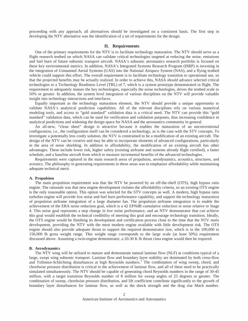
placed in the exact same spatial location and orientation, are now installed with vertical mounts from a stub wing coming off the top of the fuselage. This is not the ideal aerodynamic or structural engine installation option, but, given the underlying cost assumptions, it is relatively less costly than the initial design. The full-span wing gloves are replaced with a 2 x 20 foot leading edge laminar flow section on the left wing, and the active flow control hardware is integrated into the vertical tail (both sides) and fuselage. The requirement for the aft flight deck and associated software development to support the autonomy research is removed to reduce the NTV cost. This area would be a good candidate for a future option. Figure 3 is an isometric view of the updated NTV concept.
Figure 2. Isometric view of the initial NTV concept design.
American Institute of Aeronautics and Astronautics8
B. WeightsThe weight estimate for the NTV was updated
based upon the changes made to the design. Structural weight required for the engine installation was estimated based, in part, upon a similar installation on the Pratt &Whitney 747SP flying testbed that utilized a stub wing and vertical mount to support PW1200G engine testing. The fuselage structural weight increment for the engine installation, including a new pressure bulkhead, was 13,413 lb. Additional fuselage weight included 5,000 lb for instrumentation pallets, 6,500 lb for ballast in the tail, and a 1,000 lb placeholder for a potential future aft cockpit. Total additional fuselage weight is therefore 25,913 lb. The 171 ft2
stub wing engine mount was estimated to be 1,153 lb. The noise shield weights were estimated based upon the weight of similar aircraft structure adjusted for the area of the noise shields. Total weight for two noise shields ranged from 2450 lbfor the 1.0 fan nozzle diameter size, up to 5211 lbfor the 2.0 fan nozzle diameter shields. In addition, 260 lb for bolt-on fixed elevator surfaces for the noise shields’ trailing edge was included in the wing weight to capture the effect of control surface deflections on the noise footprint. The NLF and AFC hardware weights were estimated utilizing planning numbers from related ERA research projects. The NLF wing leading edge weight was estimated to be 500 lb; however this structure replaces the existing wing leading edge, with a net weight impact of zero. The AFC system weight was estimated to be 250 lb per side, for a total of 500 lb added to the empennage weight. Weights for the landing gear fairings (225 lb) were also included. Table 2 shows the FLOPS weight build-ups for the baseline 717-200-like model and the
Figure 3. Isometric view of updated NTV concept design.
Component717-200like
baseline weight (lb)
NTV weight(lb)
Wing 11228 11488Fuselage 13521 39434
Empennage 2626 3126Landing Gear 4146 4371
Stub Wing Engine Mount 0 1153Noise Shield 2.0 0 5211
Structure Total 31521 64783
Engines 12286 13139Systems 1918 1918
Propulsion Total 14204 15057
Furnishings & Equip. 10066 5842All other subsystems 7756 7765
Systems & Equip. Total 17822 13607
Weight Empty 63547 93447
Crew 760 450Oil & Unusable Fuel 454 455
Passenger Service 1416 130Cargo Containers 1050 0
Operating Empty Weight 67227 94482
Passengers/Test Crew 23729 2239Baggage 4770 450
Cargo 0 0
Zero Fuel Weight 95726 97171
Mission Fuel 23771 18286
Ramp (Gross) Weight 119497 115457
Table 2. Component weight build-up for baseline 717 and NTV concept.

American Institute of Aeronautics and Astronautics9
NTV design.
C. PropulsionThe updated NTV concept utilizes the same advanced GTF engines as the initial concept. Ref. 10 contains
information on the engine model, and Guynn, et al.,11 contains additional detailed information on the assumptions and modeling approach used to generate the engine data. As stated above, the engine/nacelle weight is 6,626 lb, and the sea level static thrust is 23,369 lb. An additional 10% weight increment was added to account for the pylon and pylon integration with the stub wing. The engine thrust was also de-rated to match the 717 baseline thrust of 21,000 lb, resulting in an engine scale factor = 0.9 and the final engine weights shown in Table 2.
D. Longitudinal Static StabilityA first order longitudinal static stability analysis was performed to determine if the configuration changes to the
717 baseline would have a major impact to the longitudinal stability. The neutral point location was calculated using Vorlax12 for both the baseline 717 geometry and the NTV concept. The baseline 717 fuselage, wing, engines, and horizontal tail were modeled using Vehicle Sketch Pad (VSP),13 and imported to Vorlax for analysis. The neutral point was estimated to be 68.4 ft aft of the nose. Next, the NTV geometry was modeled in VSP, including the new engines and engine location, and the worst case two nozzle exit diameter noise shield. The neutral point was estimated to be at 69.3 ft aft of the nose, a 0.9 ft aft shift due to the NTV modifications, see Figure 4. If the CG is maintained, this would result in a slightly more stable configuration; however, the CG will shift aft as well, due to the addition of the engine installation structure aft of the CG. In addition, the ballast weight can be adjusted to locate the NTV CG in the same relative location with respect to the neutral point as the baseline 717, thus preserving the static stability of the unmodified design. Based on this “quick look” analysis, the NTV concept has low pitch stability and control risk.
Figure 4. NTV neutral point movement relative to the baseline717.

American Institute of Aeronautics and Astronautics10
E. PerformanceThe most stressing NTV test flight profile would be associated with the NLF testing at transonic conditions. This
test flight mission ramp weight is 115,500 lb, with a mission fuel load of 18,286 lb. This assumes a flight crew of two, and ten test engineers and/or observers on board. Taxi out and takeoff consumes 500 lb of fuel. The climb to testing altitude takes 22 minutes, and consumes 2,690 lb of fuel. Initial testing altitude is 32,000 ft. The NTV would then provide 130 minutes at cruise conditions (Mach = 0.77) for testing purposes, burning 9,830 lb of fuel. The descent and approach for landing would consume 310 lb of fuel; resulting in a landing weight of 102,300 lb. Total fuel burned is 13,330 lb. The reserve fuel of ~5,000 lb is adequate for a 200 nm divert and a 30 minute hold, plus an additional 5%.
V. Programmatic Assumptions and Cost Analysis
A. Programmatic AssumptionsThe next step was to perform an updated cost estimate on the 2nd iteration of the NTV concept. In addition to the
technical data inputs, the cost analysis requires a set of programmatic assumptions in order to produce a full life cycle program cost estimate. A notional eight-year NTV program was defined, beginning with a two-year competitive phase. A solicitation for a Phase I effort to perform a preliminary design and cost estimate would be released during the first year. The Phase I effort would cover a 12-month period of performance, and assumes the participation of three contractor teams, funded at $2M each. Phase I efforts would include requirements refinement, systems engineering, preliminary concept design, and the delivery of a fully costed Phase II proposal. After a proposal evaluation, a downselect would occur for Phase II. Phase II would begin with a Systems Requirement Review (SRR), and proceed, within seven months, to a Preliminary Design Review (PDR). The PDR would cover all aspects of the 717 modification effort. Ten months later, a full airframe Critical Design Review (CDR) would be held to cover all aspects of the 717 modification at a high level. In parallel, a 717 aircraft would be acquired and baseline test flights would be conducted at NASA Dryden. Subsequent to the overall CDR, incremental “delta-CDR’s” would then be held to determine readiness to proceed with the hardware fabrication and integration of each increment: GTF re-engining, NLF and AFC systems, and noise reduction hardware (noise shields and landing gear fairings). After each delta-CDR, detailed design, fabrication, and integration would be performed for each increment, and then the test flights would be conducted. This incremental approach is important to capture the impacts of the individual technologies, but it requires that several activities be conducted concurrently. For example, at the beginning of year 7, the design and build effort for the NLF wing LE and AFC tail would be at the mid-way point, the noise shield design and build would be about 25% complete, the GTF flight readiness review would havejust completed, and GTF flight tests would be beginning. Figure 5 shows this eight-year program at a top-level.

American Institute of Aeronautics and Astronautics11
B. Cost EstimationOne of the key goals of the NTV study was to identify a more affordable approach to demonstrating ERA
technologies than that provided by the STV concepts. A conservative approach was maintained in preparation of the NTV cost estimate to ensure high-confidence results. A comprehensive Monte Carlo uncertainty analysis was performed to quantify the confidence levels associated with estimated costs. The objective was to be able to say with high confidence that the NTV approach is more affordable than the STV approaches.
The process used to develop the NTV cost estimate is shown in Figure 6.
Although the process is basically sequential, there is a fair amount of overlap between the steps. For example, the availability of estimating methodologies can impact both the contents of the technical baseline (parameters captured) and the estimating WBS. Similarly, the results of uncertainty analysis can lead to revisitation of the technical baseline, estimating methodologies, or cost model structure. The large, right-to-left arrow (I) in the figure
Figure 6. NTV cost estimating process.
Figure 5. Eight-year NTV program schedule.

American Institute of Aeronautics and Astronautics12
indicates that the overall process is iterative. In the NTV conceptual design effort, a complete cost estimate was developed for the initial design, and the results of the initial estimate significantly influenced the updated design. Should the NTV concept go forward, this design-estimating cycle will continue, and as the design and cost estimating methodologies are refined, the cost uncertainty will decrease.
C. Scope of EstimateThe NTV cost estimate includes the complete cost of the project starting with concept definition and finishing
with the end of flight operations and documentation of results. Government and contractor costs are included. Cost of all hardware and software required for the project is included – no outside or contractor contributions or legacy hardware or software are assumed. The estimate does not include salvage or disposal costs.
D. Technical and Programmatic BaselineTo establish the technical and programmatic baseline for cost estimating, the cost team established preliminary
parametric input requirements based on prior experience with similar projects. The management and technical team then provided the needed parameters based on the NTV conceptual design. The inputs comprising the cost estimating technical and programmatic baseline included:
Weights at the subsystem level for the baseline aircraft as well as equipment added and equipment removed
Design reuse factors (0.0 equates to a totally new design, 1.0 equates to an off-the-shelf subsystem)Composite material factors (0.0 equates to a subsystem made entirely of traditional materials, 1.0 equates
to an all-composite subsystem)Software size for various software subsystems in Source Lines Of Code (SLOC)Ground and flight test hoursNASA staffing by WBS in terms of Full Time Equivalent (FTE) civil servants and Work Year Equivalent
(WYE) support contractorsSchedule showing critical phases of the project
E. Ground Rules and AssumptionsThe ground rules and estimating assumptions agreed upon for the NTV estimate were as follows:
Tooling costs for a one-off demonstration build are reduced to 80% of what they would be for a full scale development program.
No spare parts are purchased for the basic 717 aircraft; spares are assumed to be available for purchase from Boeing or others.
Two high bypass ratio GTF engines will be purchased off-the-shelf from Pratt and Whitney in addition to the engines included with the 717 aircraft; no spare engines will be purchased.
The wind tunnel model is assumed to be equivalent in size, weight, and complexity to the model to be built for the ERA Propulsion Airframe Integration Hybrid Wing Body Integrated Technology Demonstration.
Each of the three wind tunnel tests will require 25 days of wind tunnel occupancy time.CER estimated costs included the complete development costs for a typical, contracted aircraft development
program. Government Technology Development personnel costs after the start of contracted effort in 2015 are included in the CER-estimated costs (and should be subtracted out in final cost displays and shown separately).
Ballast added to the rear of the aircraft is assumed to cost 5% on a per pound basis of the cost of normal fuselage structure.
The aircraft modification contractor fee is assumed to be 8% added to cost.

American Institute of Aeronautics and Astronautics13
F. Estimating Work Breakdown StructureThe NTV estimating WBS breaks hardware and software
costs down to the major subsystem level of detail. The WBS is shown in Table 3.
For each row in the WBS breakout, costs are also broken out by design labor, tooling labor, tooling materials, fabrication/installation labor, and fabrication/installation materials.
G. Cost Estimating MethodologiesCost for airframe and engine subsystems were estimated
using CERs from the Tailored Cost Model (TCM). The TCM is a set of parametric CERs originally compiled by the McDonnell Douglas Corporation in the 1980s and 1990s. The model is a combination of in-house McDonnell Douglas CERs and CERs developed at the RAND Corporation. TCM has been used extensively at NASA for various analyses and is available to NASA users as part of the Process Based Economic Analysis Tool (PBEAT).
The TCM CERs have recently (as of 12/14/2012) been validated and in some cases updated for use in the Probabilistic Technology Investment Ranking System (PTIRS). The TCM database includes both commercial and military aircraft and it was important to verify that the model was not biased towards military aircraft which are generally perceived to cost more than commercial aircraft on a dollars per-pound basis.
The TCM CERs are weight-based, with complexity cost adjustment factors for composite materials in the case of structural subsystems. The CERs all have the following form:
Cost = a*Weightb (1 + cP)
Where:
a = constantWeight = weight of subsystem, lbb = constantc = composite material cost factor relative to
traditional structural materialsP = portion of structural subsystem composed of
composite materials by weight
The TCM CERs estimate the costs of designing and building an all-new aircraft. Because the NTV is a modified aircraft, it requires estimating the costs of adding some new components to an existing aircraft, and in some cases removing existing components to make room for the new components. The TCM CERs address the costs of designing, fabricating, and installing the new components. However, as CERs representing the cost of removing subsystems from an existing aircraft were not available, a creative approach was required. The approach chosen is based on the observation that disassembling equipment generally requires an amount of effort similar to assembling it. The classical rule of
Table 3. Estimating WBS.

American Institute of Aeronautics and Astronautics14
thumb in cost estimating is that integration and assembly of a group of parts will cost roughly 10% of the total cost of the parts to be integrated. Therefore, the costs of disassembling equipment should also be roughly 10% of the total cost of the parts to be de-integrated. The following equation for was used to estimate the disassembly costs:
Cost = Factor * CER(Total Wt) * Removed Wt / Total Wt
Where:Factor = disassembly cost factor from the list below:
design labor: 0.10tooling labor: 0.10manufacturing labor: 0.15manufacturing material: 0.01
CER() = TCM CER for subsystemTotal Wt = weight of original subsystem, lbRemoved Wt = weight of equipment removed from subsystem, lb
Since some of the new components added to the NTV aircraft were similar to previously developed equipment, it was necessary to adjust the design and tooling costs of those components to represent design reuse. New Design factors were specified by the design team as part of the technical baseline. These factors were applied directly to the costs estimated by the design labor and tooling labor CERs.
The PRICE-S™ model was used for software cost estimating. The PRICE-S™ model is a commercially available cost model that has been widely used for several decades. The model estimates costs based on SLOC and numerous complexity inputs, all of which we set to the default settings for commercial avionics software. As mentioned above SLOC counts were provided by the technical team as part of the technical and programmatic baseline.
NASA staffing was specified as part of the technical and programmatic baseline in terms of FTEs for civil servants and WYEs for support contractors. Fully burdened labor rates were applied to those headcounts to estimate year-by-year costs. The rates used were the same average rates used by the ERA Project in planning and budgeting ongoing technology demonstration efforts.
The TCM CERs estimate labor costs in terms of staff hours. Fully-loaded contractor labor rates were applied based on three similarly extensive aircraft modification projects (NASA, MDA, USAF/AFRL).
Attempts to find current market prices for used 717 aircraft were fruitless. There did not appear to be any for sale when the analysis was performed. However, due to the age of the 717, one or more are expected to be available in the timeframe required to support a future NTV program effort. A representative cost of a used 717 aircraft was determined by estimating the residual value of the aircraft to its owners at the planned time of NTV aircraft acquisition (2017). The majority of airlines assume a 30-year depreciation life for new aircraft. Each year, 1/30th of the initial cost of each aircraft is charged to depreciation. Assuming that the NTV Project would buy one of the oldest 717s purchased in 1999, eighteen years of depreciation would apply. This means that the book value to an airline in 2017 would be 40% of its original purchase price.
The airborne instrumentation pallets required for NTV flight testing were estimated using a dollars-per-poundfactor based on a similar NASA airborne science project which includes several pallets of data acquisition and command and control hardware.
Wind tunnel daily costs were estimated based on quotes from wind tunnel operators at NASA Langley Research Center in support of ERA Integrated Technology Demonstrations. Flight test operations costs were based on similar data from Dryden Flight Research Center.
H. Cost ModelAll of the CERs and other estimating methodologies described above were implemented using the ACEIT™
suite of cost estimating tools. ACEIT™ is a general cost modeling tool that provides a spreadsheet environment with built in capabilities specific to cost estimating. ACEIT™ was developed over twenty years ago by Tecolote Research under US Air Force funding, and has evolved into a standard cost estimating tool of DoD, NASA, and other branches of the federal government. In addition to powerful built-in reporting and graphics, ACEIT™ includes an extremely flexible Monte Carlo engine for uncertainty analysis. Any variable in the cost model can be given an uncertainty distribution. A broad variety of uncertainty distribution shapes are available.

American Institute of Aeronautics and Astronautics15
I. Uncertainty AnalysisUncertainty in cost modeling falls into two broad categories: model inherent uncertainty and model input
uncertainty. Model inherent uncertainty consists of the statistical noise around the CER coefficients and cost factors comprising the cost model. The distributions specified to represent the uncertainty in the NTV cost model are as follows:
Design and tooling CER inherent uncertainty: Standard Error of Estimate = 0.40 in log-space (i.e. 90th
percentile = 1.70 times point estimate)Manufacturing CER inherent uncertainty: Standard Error of Estimate = 0.30 in log-space (i.e. 90%
percentile = 1.54 times point estimate)One-off demonstration tooling cost reduction factor: triangular distribution, -50%/+25%717 purchase cost: triangular distribution, -20%/+25%Engine purchase cost: triangular distribution, -20%/+25%Ballast weight cost equivalency factor: triangular distribution, ±50%Disintegration cost factors: triangular distribution, ±50%Contractor wrap rates: triangular distribution, -22%/+33% (based on analogous projects).
The following uncertainty ranges for NTV cost model inputs were supplied by or negotiated with the technical and programmatic team:
Added/Subtracted weights: triangular distribution, -20%/+25%Wind tunnel occupancy days: triangular distribution, -10%/+67%Flight test hours: triangular distribution, -25%/+60%Software staff-hours: triangular distribution, ±25%Contractor Project Management and Project Analysis headcounts: triangular distribution, -10%/+100%FTEs and WYE headcounts: triangular distribution, ±20%
J. ResultsFigure 7 through Figure 10 illustrate the cost estimating results for the Final Conceptual Design. Figure 7 is a
cost summary showing then-year costs at the 50th percentile confidence level, as well as the amount of cost reserve required to budget to the 80th percentile confidence level.
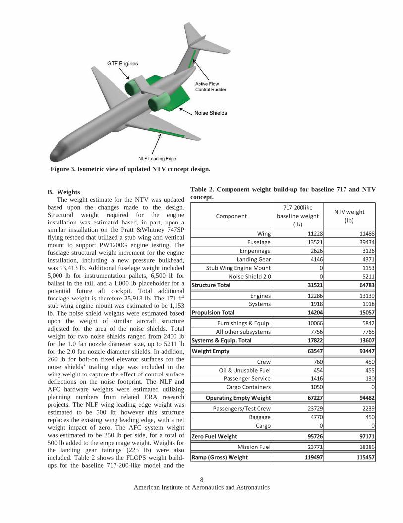
Figure 8 shows the confidence levels associated with different levels of cost. The blue S-curve represents the cumulative distribution function of total project cost. The red square represents the point estimate, which is the cost calculated deterministically with no consideration of uncertainty. The point estimate has an equivalent confidence level of 31%. The dotted maroon line is the cumulative distribution function of total cost for the initial NTV design, which is included to show how the total project cost decreased and the uncertainty about the total cost also decreased as the team refined its understanding of the conceptual design.
Figure 7. Project cost summary.
American Institute of Aeronautics and Astronautics16
Figure 9 shows the top 20 elements of cost. The top three elements are related to modifying the fuselage to support the mid-fuselage, top-suspended GTF engines, which requires extensive structural modification to the center fuselage. Predictably, vehicle integration is the next major cost element. Sound shield production is next on the list because the test plan calls for three sets of different sized sound shields. Contractor fee, 717 purchase, and engine purchase round out the highest-cost items.
Figure 8. Project total cost versus confidence level.

American Institute of Aeronautics and Astronautics17
Figure 10 shows how the costs are phased over the life of the project assuming a start date in 2013. Peak annual funding of $146M is required in FY 2018. Contract funding required in 2018 is $139M.
Figure 9. Cost Drivers.
Figure 10. Required funding profile.

American Institute of Aeronautics and Astronautics18
The funding profile shown in Figure 10 has the ramp-up ramp-down shape typical of product development programs as opposed to the flat-line shape of technology development programs. The dashed red line represents the initialestimate which included an additional two-year effort for open rotor testing that was removed from the final iteration.
A cross-check estimate was prepared using an aircraft modification cost model developed by Boeing in support of the Airborne Laser (ABL) Program. This was an unpublished model, based on three prior unnamed Boeing aircraft modification projects. The System Test and Evaluation scenario built into the model assumed the aircraft would be FAA certified for flight in non-restricted airspace. Backing out the impact of the more stringent test program, the cross-check estimate obtained is ~$545M, which is 10% higher than the primary point estimate of $497M in then-year dollars.
VI. ConclusionA conceptual design and cost estimate for a NTV research aircraft was presented. The approach of modifying an
existing aircraft as opposed to starting with a clean sheet design was intended to provide a more affordable alternative concept for NASA decision makers. Although this approach does not capture the unconventional configuration advantages, there are several attractive features to be considered. Utilizing an existing aircraft as opposed to a proprietary clean sheet design should result in a more open data set enabling the widest possible dissemination and overall benefit to the public. The existing aircraft can be tested in an un-modified baseline configuration, and then modified in an incremental manner, yielding well-defined technology impacts and tool validation opportunities. This incremental approach is a key attribute of a successful flight research vehicle, and was embraced even though it yielded a longer schedule and higher cost than an approach that would perform all the modifications simultaneously resulting in a single series of flight tests.
The 50% confidence level cost estimate of $526M is a relatively large amount, even spread over eight years, for NASA’s Aeronautics program. There are several significant opportunities for weight and cost savings that could be explored in future iterations of the design. Figure 9 shows the cost drivers associated with the current concept. The center fuselage modification costs and the costs of fabricating the noise shields have the potential to be reduced through the use of rapid prototyping approaches and design optimization. There are also partnership opportunities that could result in cost sharing agreements as well. These would have to be balanced against the desire to keep the test data open and available.
The NTV concept presented here is only one of many potential alternatives for a large scale subsonic flight research vehicle. The industry developed STV concepts are options, as well as other ideas such as utilizing aero-tow techniques to test a more affordable un-powered unconventional configuration demonstrator. The recommended next step in developing options is to perform a full Analysis of Alternatives (AoA) study, which would produce a set of alternatives developed on a consistent basis resulting in the clear identification of cost and capability metrics.
AcknowledgmentsThe authors thank the following NASA engineers for their contributions to this study: Andy Hahn, Chris
Hughes, Russ Thomas, Dawn Jegley, Jeff Viken, Ken Goodrich, Bob Curry, Frank Gern, Mark Guynn, and Karl Geiselhart.

American Institute of Aeronautics and Astronautics19
References
1Bonet, J.T., et al., “Environmentally Responsible Aviation (ERA) Project – N+2 Advanced Vehicle Concepts Study and Conceptual Design of Subscale Test Vehicle (STV) Final Report”, NASA/CR-2012-XX, submitted for publication.2 Martin, K.C., and McKay, B.G., “Environmentally Responsible Aviation Lockheed Martin ERA Team”, NASA/CR-2012-XX, submitted for publication.3 Drake, A., Harris, C.A., Komadina, S.C., Wang, D.P., Bender, A.M., “Environmentally Responsible Aviation N+2 Advanced Vehicle Study Final Technical Report”, NASA/CR-2012-XX, submitted for publication.4 Harris, W.L., et al., “Recapturing NASA’s Aeronautics Flight Research Capabilities”, The National Academies Press, ISBN 978-0-309-25538-7, URL: http://www.nap.edu/catalog.php?record_id=13384 [cited 1 Jan 2013].5 Joslin, R.D., “Overview of Laminar Flow Control”, NASA/TP-1998-208705, October, 1998.6 Thomas, R.H., Burley, C.L., Olson, E.D., “Hybrid Wing Body Aircraft System Noise Assessment With Propulsion Airframe Aeroacoustic Experiments”, AIAA 2010-3913, June, 2010.7 National Transportation Safety Board, Aviation Accident Reports, http://www.ntsb.gov/investigations/reports_aviation.html,accessed 6/13/2013.8 Jackson, P., et al., “Jane’s All the World’s Aircraft 2009-2010”, p. 966-967.9 Boeing 717-200 Airplane Characteristics for Airport Planning Documentation, http://www.boeing.com/commercial/airports/717.htm, accessed 2/6/13.10 Guynn, M.D., et al., “Refined Exploration of Turbofan Design Options for an Advanced Single-Aisle Transport”, NASA/TM-2011-216883, January 2011.11 Guynn, M.D., et al., “Engine Concept Study for an Advanced Single-Aisle Transport”, NASA/TM-2009-215784, August, 2009.12 Miranda, L.R., Elliott, R.D., Baker, W.M., “A Generalized Vortex Lattice Method for Subsonic and Supersonic Flow Applications”, NASA CR-2865, December, 1977.13 Hahn, A.S., “Vehicle Sketch Pad: A Parametric Geometry Modeler for Conceptual Aircraft Design”, AIAA 2010-657, January, 2010.