concepts&examples screenosreferenceguide ·...
TRANSCRIPT

Concepts & ExamplesScreenOS Reference Guide
Virtual Systems
Release
6.3.0, Rev. 02
Published: 2012-12-10
Revision 02
Copyright © 2012, Juniper Networks, Inc.

Juniper Networks, Inc.1194 North Mathilda AvenueSunnyvale, California 94089USA408-745-2000www.juniper.net
Juniper Networks, Junos, Steel-Belted Radius, NetScreen, and ScreenOS are registered trademarks of Juniper Networks, Inc. in the UnitedStates and other countries. JunosE is a trademark of Juniper Networks, Inc. All other trademarks, service marks, registered trademarks, orregistered service marks are the property of their respective owners.Juniper Networks assumes no responsibility for any inaccuracies in this document. Juniper Networks reserves the right to change, modify,transfer, or otherwise revise this publication without notice.Products made or sold by Juniper Networks or components thereof might be covered by one or more of the following patents that areowned by or licensed to Juniper Networks: U.S. Patent Nos. 5,473,599, 5,905,725, 5,909,440, 6,192,051, 6,333,650, 6,359,479, 6,406,312,6,429,706, 6,459,579, 6,493,347, 6,538,518, 6,538,899, 6,552,918, 6,567,902, 6,578,186, and 6,590,785.Copyright © 2009, Juniper Networks, Inc.All rights reserved.
Revision HistoryDecember 2012—Revision 02
Content subject to change. The information in this document is current as of the date listed in the revision history.
SOFTWARE LICENSE
The terms and conditions for using this software are described in the software license contained in the acknowledgment to your purchaseorder or, to the extent applicable, to any reseller agreement or end-user purchase agreement executed between you and Juniper Networks.By using this software, you indicate that you understand and agree to be bound by those terms and conditions.
Generally speaking, the software license restricts the manner in which you are permitted to use the software and may contain prohibitionsagainst certain uses. The software license may state conditions under which the license is automatically terminated. You should consultthe license for further details.
For complete product documentation, please see the Juniper Networks Website at www.juniper.net/techpubs.
ENDUSER LICENSE AGREEMENT
The Juniper Networks product that is the subject of this technical documentation consists of (or is intended for use with) Juniper Networkssoftware. Use of such software is subject to the terms and conditions of the End User License Agreement (“EULA”) posted at
http://www.juniper.net/support/eula.html. By downloading, installing or using such software, you agree to the terms and conditionsof that EULA.
Copyright © 2012, Juniper Networks, Inc.ii

Abbreviated Table of Contents
About This Guide . . . . . . . . . . . . . . . . . . . . . . . . . . . . . . . . . . . . . . . . . . . . . . . . . xiii
Part 1 Virtual Systems
Chapter 1 Virtual Systems . . . . . . . . . . . . . . . . . . . . . . . . . . . . . . . . . . . . . . . . . . . . . . . . . . . . 3
Chapter 2 Traffic Sorting . . . . . . . . . . . . . . . . . . . . . . . . . . . . . . . . . . . . . . . . . . . . . . . . . . . . 35
Chapter 3 VLAN-Based Traffic Classification . . . . . . . . . . . . . . . . . . . . . . . . . . . . . . . . . . 45
Chapter 4 IP-Based Traffic Classification . . . . . . . . . . . . . . . . . . . . . . . . . . . . . . . . . . . . . . 75
Part 2 Index
Index . . . . . . . . . . . . . . . . . . . . . . . . . . . . . . . . . . . . . . . . . . . . . . . . . . . . . . . . . . . . 83
iiiCopyright © 2012, Juniper Networks, Inc.

Copyright © 2012, Juniper Networks, Inc.iv
Virtual Systems

Table of Contents
About This Guide . . . . . . . . . . . . . . . . . . . . . . . . . . . . . . . . . . . . . . . . . . . . . . . . . xiii
Document Conventions . . . . . . . . . . . . . . . . . . . . . . . . . . . . . . . . . . . . . . . . . . . . . . xiii
Document Feedback . . . . . . . . . . . . . . . . . . . . . . . . . . . . . . . . . . . . . . . . . . . . . . . . xv
Requesting Technical Support . . . . . . . . . . . . . . . . . . . . . . . . . . . . . . . . . . . . . . . . xvi
Part 1 Virtual Systems
Chapter 1 Virtual Systems . . . . . . . . . . . . . . . . . . . . . . . . . . . . . . . . . . . . . . . . . . . . . . . . . . . . 3
Overview . . . . . . . . . . . . . . . . . . . . . . . . . . . . . . . . . . . . . . . . . . . . . . . . . . . . . . . . . . . 3
Vsys Objects . . . . . . . . . . . . . . . . . . . . . . . . . . . . . . . . . . . . . . . . . . . . . . . . . . . . . . . . 4
Creating a Virtual System Object and Admin . . . . . . . . . . . . . . . . . . . . . . . . . . . 5
WebUI . . . . . . . . . . . . . . . . . . . . . . . . . . . . . . . . . . . . . . . . . . . . . . . . . . . . . . 6
CLI . . . . . . . . . . . . . . . . . . . . . . . . . . . . . . . . . . . . . . . . . . . . . . . . . . . . . . . . 6
Setting a Default Virtual Router for a Virtual System . . . . . . . . . . . . . . . . . . . . . 7
Binding Zones to a Shared Virtual Router . . . . . . . . . . . . . . . . . . . . . . . . . . . . . 7
WebUI . . . . . . . . . . . . . . . . . . . . . . . . . . . . . . . . . . . . . . . . . . . . . . . . . . . . . . 8
CLI . . . . . . . . . . . . . . . . . . . . . . . . . . . . . . . . . . . . . . . . . . . . . . . . . . . . . . . . 8
Defining Identical Names for Zones Across Vsys . . . . . . . . . . . . . . . . . . . . . . . . . . . 8
Logging In as a Virtual System Admin . . . . . . . . . . . . . . . . . . . . . . . . . . . . . . . . . . . . 9
WebUI . . . . . . . . . . . . . . . . . . . . . . . . . . . . . . . . . . . . . . . . . . . . . . . . . . . . . . . . . 9
CLI . . . . . . . . . . . . . . . . . . . . . . . . . . . . . . . . . . . . . . . . . . . . . . . . . . . . . . . . . . . 10
Virtual System Profiles . . . . . . . . . . . . . . . . . . . . . . . . . . . . . . . . . . . . . . . . . . . . . . . 10
Virtual System Session Counters . . . . . . . . . . . . . . . . . . . . . . . . . . . . . . . . . . . . 11
Virtual System Session Information . . . . . . . . . . . . . . . . . . . . . . . . . . . . . . . . . . 11
CLI . . . . . . . . . . . . . . . . . . . . . . . . . . . . . . . . . . . . . . . . . . . . . . . . . . . . . . . . 12
Behavior in High-Availability Pairs . . . . . . . . . . . . . . . . . . . . . . . . . . . . . . . . . . . 12
Creating a Vsys Profile . . . . . . . . . . . . . . . . . . . . . . . . . . . . . . . . . . . . . . . . . . . . 12
Setting Resource Limits . . . . . . . . . . . . . . . . . . . . . . . . . . . . . . . . . . . . . . . . . . . 13
WebUI . . . . . . . . . . . . . . . . . . . . . . . . . . . . . . . . . . . . . . . . . . . . . . . . . . . . . 14
CLI . . . . . . . . . . . . . . . . . . . . . . . . . . . . . . . . . . . . . . . . . . . . . . . . . . . . . . . . 14
Adding Session Limits Through Virtual-System Profile Assignment . . . . . . . . 14
WebUI . . . . . . . . . . . . . . . . . . . . . . . . . . . . . . . . . . . . . . . . . . . . . . . . . . . . . 15
CLI . . . . . . . . . . . . . . . . . . . . . . . . . . . . . . . . . . . . . . . . . . . . . . . . . . . . . . . . 15
WebUI . . . . . . . . . . . . . . . . . . . . . . . . . . . . . . . . . . . . . . . . . . . . . . . . . . . . . 15
CLI . . . . . . . . . . . . . . . . . . . . . . . . . . . . . . . . . . . . . . . . . . . . . . . . . . . . . . . . 15
Setting a Session Override . . . . . . . . . . . . . . . . . . . . . . . . . . . . . . . . . . . . . . . . 15
WebUI . . . . . . . . . . . . . . . . . . . . . . . . . . . . . . . . . . . . . . . . . . . . . . . . . . . . . 15
CLI . . . . . . . . . . . . . . . . . . . . . . . . . . . . . . . . . . . . . . . . . . . . . . . . . . . . . . . . 15
WebUI . . . . . . . . . . . . . . . . . . . . . . . . . . . . . . . . . . . . . . . . . . . . . . . . . . . . . 16
CLI . . . . . . . . . . . . . . . . . . . . . . . . . . . . . . . . . . . . . . . . . . . . . . . . . . . . . . . . 16
vCopyright © 2012, Juniper Networks, Inc.

Deleting a Vsys Profile . . . . . . . . . . . . . . . . . . . . . . . . . . . . . . . . . . . . . . . . . . . . 16
WebUI . . . . . . . . . . . . . . . . . . . . . . . . . . . . . . . . . . . . . . . . . . . . . . . . . . . . . 16
CLI . . . . . . . . . . . . . . . . . . . . . . . . . . . . . . . . . . . . . . . . . . . . . . . . . . . . . . . . 16
Viewing Vsys Settings . . . . . . . . . . . . . . . . . . . . . . . . . . . . . . . . . . . . . . . . . . . . 16
Viewing Overrides . . . . . . . . . . . . . . . . . . . . . . . . . . . . . . . . . . . . . . . . . . . . 16
Viewing a Profile . . . . . . . . . . . . . . . . . . . . . . . . . . . . . . . . . . . . . . . . . . . . . 17
Viewing Session Statistics . . . . . . . . . . . . . . . . . . . . . . . . . . . . . . . . . . . . . 19
Sharing and Partitioning CPU Resources . . . . . . . . . . . . . . . . . . . . . . . . . . . . . . . . . 19
Configuring CPU Weight . . . . . . . . . . . . . . . . . . . . . . . . . . . . . . . . . . . . . . . . . . 20
WebUI . . . . . . . . . . . . . . . . . . . . . . . . . . . . . . . . . . . . . . . . . . . . . . . . . . . . . 21
CLI . . . . . . . . . . . . . . . . . . . . . . . . . . . . . . . . . . . . . . . . . . . . . . . . . . . . . . . . 21
Fair Mode Packet Flow . . . . . . . . . . . . . . . . . . . . . . . . . . . . . . . . . . . . . . . . . . . . 21
Returning from Fair Mode to Shared Mode . . . . . . . . . . . . . . . . . . . . . . . . . . . 22
Enabling the CPU Limit Feature . . . . . . . . . . . . . . . . . . . . . . . . . . . . . . . . . . . . 22
WebUI . . . . . . . . . . . . . . . . . . . . . . . . . . . . . . . . . . . . . . . . . . . . . . . . . . . . . 22
CLI . . . . . . . . . . . . . . . . . . . . . . . . . . . . . . . . . . . . . . . . . . . . . . . . . . . . . . . . 22
Measuring CPU Usage . . . . . . . . . . . . . . . . . . . . . . . . . . . . . . . . . . . . . . . . . . . . 23
Detailed Session Scan Debugging . . . . . . . . . . . . . . . . . . . . . . . . . . . . . . . . . . 25
Setting the Shared-to-Fair Mode CPU Utilization Threshold . . . . . . . . . . . . . 26
WebUI . . . . . . . . . . . . . . . . . . . . . . . . . . . . . . . . . . . . . . . . . . . . . . . . . . . . . 26
CLI . . . . . . . . . . . . . . . . . . . . . . . . . . . . . . . . . . . . . . . . . . . . . . . . . . . . . . . 26
Configuring a Method for Returning to Shared Mode . . . . . . . . . . . . . . . . . . . 28
WebUI . . . . . . . . . . . . . . . . . . . . . . . . . . . . . . . . . . . . . . . . . . . . . . . . . . . . 28
CLI . . . . . . . . . . . . . . . . . . . . . . . . . . . . . . . . . . . . . . . . . . . . . . . . . . . . . . . 29
Setting a Fixed Root Vsys CPU Weight . . . . . . . . . . . . . . . . . . . . . . . . . . . . . . 29
Virtual Systems and Virtual Private Networks . . . . . . . . . . . . . . . . . . . . . . . . . . . . 30
Viewing Security Associations . . . . . . . . . . . . . . . . . . . . . . . . . . . . . . . . . . . . . 30
WebUI . . . . . . . . . . . . . . . . . . . . . . . . . . . . . . . . . . . . . . . . . . . . . . . . . . . . 30
CLI . . . . . . . . . . . . . . . . . . . . . . . . . . . . . . . . . . . . . . . . . . . . . . . . . . . . . . . 30
WebUI . . . . . . . . . . . . . . . . . . . . . . . . . . . . . . . . . . . . . . . . . . . . . . . . . . . . 30
CLI . . . . . . . . . . . . . . . . . . . . . . . . . . . . . . . . . . . . . . . . . . . . . . . . . . . . . . . 30
Viewing IKE Cookies . . . . . . . . . . . . . . . . . . . . . . . . . . . . . . . . . . . . . . . . . . . . . 30
WebUI . . . . . . . . . . . . . . . . . . . . . . . . . . . . . . . . . . . . . . . . . . . . . . . . . . . . . 31
CLI . . . . . . . . . . . . . . . . . . . . . . . . . . . . . . . . . . . . . . . . . . . . . . . . . . . . . . . . 31
WebUI . . . . . . . . . . . . . . . . . . . . . . . . . . . . . . . . . . . . . . . . . . . . . . . . . . . . . 31
CLI . . . . . . . . . . . . . . . . . . . . . . . . . . . . . . . . . . . . . . . . . . . . . . . . . . . . . . . . 31
Policy Scheduler . . . . . . . . . . . . . . . . . . . . . . . . . . . . . . . . . . . . . . . . . . . . . . . . . . . . 31
Creating a Policy Scheduler . . . . . . . . . . . . . . . . . . . . . . . . . . . . . . . . . . . . . . . . 31
WebUI . . . . . . . . . . . . . . . . . . . . . . . . . . . . . . . . . . . . . . . . . . . . . . . . . . . . . 31
CLI . . . . . . . . . . . . . . . . . . . . . . . . . . . . . . . . . . . . . . . . . . . . . . . . . . . . . . . . 32
Binding a Policy Schedule to a Policy . . . . . . . . . . . . . . . . . . . . . . . . . . . . . . . . 32
WebUI . . . . . . . . . . . . . . . . . . . . . . . . . . . . . . . . . . . . . . . . . . . . . . . . . . . . . 32
CLI . . . . . . . . . . . . . . . . . . . . . . . . . . . . . . . . . . . . . . . . . . . . . . . . . . . . . . . . 32
Viewing Policy Schedules . . . . . . . . . . . . . . . . . . . . . . . . . . . . . . . . . . . . . . . . . 32
WebUI . . . . . . . . . . . . . . . . . . . . . . . . . . . . . . . . . . . . . . . . . . . . . . . . . . . . . 32
CLI . . . . . . . . . . . . . . . . . . . . . . . . . . . . . . . . . . . . . . . . . . . . . . . . . . . . . . . . 33
Deleting a Policy Schedule . . . . . . . . . . . . . . . . . . . . . . . . . . . . . . . . . . . . . . . . 33
WebUI . . . . . . . . . . . . . . . . . . . . . . . . . . . . . . . . . . . . . . . . . . . . . . . . . . . . . 33
CLI . . . . . . . . . . . . . . . . . . . . . . . . . . . . . . . . . . . . . . . . . . . . . . . . . . . . . . . . 33
Copyright © 2012, Juniper Networks, Inc.vi
Virtual Systems
Chapter 2 Traffic Sorting . . . . . . . . . . . . . . . . . . . . . . . . . . . . . . . . . . . . . . . . . . . . . . . . . . . . 35
Overview . . . . . . . . . . . . . . . . . . . . . . . . . . . . . . . . . . . . . . . . . . . . . . . . . . . . . . . . . . 35
Sorting Traffic . . . . . . . . . . . . . . . . . . . . . . . . . . . . . . . . . . . . . . . . . . . . . . . . . . 35
Sorting Through Traffic . . . . . . . . . . . . . . . . . . . . . . . . . . . . . . . . . . . . . . . . . . . 36
Dedicated and Shared Interfaces . . . . . . . . . . . . . . . . . . . . . . . . . . . . . . . . . . 40
Dedicated Interfaces . . . . . . . . . . . . . . . . . . . . . . . . . . . . . . . . . . . . . . . . . 40
Shared Interfaces . . . . . . . . . . . . . . . . . . . . . . . . . . . . . . . . . . . . . . . . . . . . 41
Importing and Exporting Physical Interfaces . . . . . . . . . . . . . . . . . . . . . . . . . . . . . 42
Importing a Physical Interface to a Virtual System . . . . . . . . . . . . . . . . . . . . . 43
WebUI . . . . . . . . . . . . . . . . . . . . . . . . . . . . . . . . . . . . . . . . . . . . . . . . . . . . . 43
CLI . . . . . . . . . . . . . . . . . . . . . . . . . . . . . . . . . . . . . . . . . . . . . . . . . . . . . . . 43
Exporting a Physical Interface from a Virtual System . . . . . . . . . . . . . . . . . . . 43
WebUI . . . . . . . . . . . . . . . . . . . . . . . . . . . . . . . . . . . . . . . . . . . . . . . . . . . . . 43
CLI . . . . . . . . . . . . . . . . . . . . . . . . . . . . . . . . . . . . . . . . . . . . . . . . . . . . . . . 44
Chapter 3 VLAN-Based Traffic Classification . . . . . . . . . . . . . . . . . . . . . . . . . . . . . . . . . . 45
Overview . . . . . . . . . . . . . . . . . . . . . . . . . . . . . . . . . . . . . . . . . . . . . . . . . . . . . . . . . . 45
VLANs . . . . . . . . . . . . . . . . . . . . . . . . . . . . . . . . . . . . . . . . . . . . . . . . . . . . . . . . 45
VLANs with Vsys . . . . . . . . . . . . . . . . . . . . . . . . . . . . . . . . . . . . . . . . . . . . . . . . 46
VLANs with VSDs . . . . . . . . . . . . . . . . . . . . . . . . . . . . . . . . . . . . . . . . . . . . . . . 47
Example: Binding VLAN Group with VSD . . . . . . . . . . . . . . . . . . . . . . . . . 47
Configuring Layer 2 Virtual Systems . . . . . . . . . . . . . . . . . . . . . . . . . . . . . . . . . . . . 48
Example 1: Configuring a Single Port . . . . . . . . . . . . . . . . . . . . . . . . . . . . . . . . 50
WebUI . . . . . . . . . . . . . . . . . . . . . . . . . . . . . . . . . . . . . . . . . . . . . . . . . . . . . 51
CLI . . . . . . . . . . . . . . . . . . . . . . . . . . . . . . . . . . . . . . . . . . . . . . . . . . . . . . . . 52
Example 2: Configuring Two 4-Port Aggregates with Separate Untrust
Zones . . . . . . . . . . . . . . . . . . . . . . . . . . . . . . . . . . . . . . . . . . . . . . . . . . . . . 53
WebUI . . . . . . . . . . . . . . . . . . . . . . . . . . . . . . . . . . . . . . . . . . . . . . . . . . . . . 55
CLI . . . . . . . . . . . . . . . . . . . . . . . . . . . . . . . . . . . . . . . . . . . . . . . . . . . . . . . . 57
Example 3: Configuring Two 4-Port Aggregates that Share One Untrusted
Zone . . . . . . . . . . . . . . . . . . . . . . . . . . . . . . . . . . . . . . . . . . . . . . . . . . . . . . 59
WebUI . . . . . . . . . . . . . . . . . . . . . . . . . . . . . . . . . . . . . . . . . . . . . . . . . . . . . 61
CLI . . . . . . . . . . . . . . . . . . . . . . . . . . . . . . . . . . . . . . . . . . . . . . . . . . . . . . . 62
Defining Subinterfaces and VLAN Tags . . . . . . . . . . . . . . . . . . . . . . . . . . . . . . . . . 65
WebUI . . . . . . . . . . . . . . . . . . . . . . . . . . . . . . . . . . . . . . . . . . . . . . . . . . . . . . . . 66
CLI . . . . . . . . . . . . . . . . . . . . . . . . . . . . . . . . . . . . . . . . . . . . . . . . . . . . . . . . . . . 67
Communicating Between Virtual Systems . . . . . . . . . . . . . . . . . . . . . . . . . . . . . . . 67
WebUI . . . . . . . . . . . . . . . . . . . . . . . . . . . . . . . . . . . . . . . . . . . . . . . . . . . . . . . . 68
CLI . . . . . . . . . . . . . . . . . . . . . . . . . . . . . . . . . . . . . . . . . . . . . . . . . . . . . . . . . . . 70
VLAN Retagging . . . . . . . . . . . . . . . . . . . . . . . . . . . . . . . . . . . . . . . . . . . . . . . . . . . . 70
Configuring VLAN Retagging . . . . . . . . . . . . . . . . . . . . . . . . . . . . . . . . . . . . . . . 71
Example . . . . . . . . . . . . . . . . . . . . . . . . . . . . . . . . . . . . . . . . . . . . . . . . . . . 72
Chapter 4 IP-Based Traffic Classification . . . . . . . . . . . . . . . . . . . . . . . . . . . . . . . . . . . . . . 75
Overview . . . . . . . . . . . . . . . . . . . . . . . . . . . . . . . . . . . . . . . . . . . . . . . . . . . . . . . . . . 75
Managing Inter-Vsys Traffic with a Shared DMZ Zone . . . . . . . . . . . . . . . . . . . . . . 76
WebUI . . . . . . . . . . . . . . . . . . . . . . . . . . . . . . . . . . . . . . . . . . . . . . . . . . . . . . . . 76
CLI . . . . . . . . . . . . . . . . . . . . . . . . . . . . . . . . . . . . . . . . . . . . . . . . . . . . . . . . . . . 76
viiCopyright © 2012, Juniper Networks, Inc.
Table of Contents
Designating an IP Range to the Root System . . . . . . . . . . . . . . . . . . . . . . . . . . . . . 77
WebUI . . . . . . . . . . . . . . . . . . . . . . . . . . . . . . . . . . . . . . . . . . . . . . . . . . . . . . . . 77
CLI . . . . . . . . . . . . . . . . . . . . . . . . . . . . . . . . . . . . . . . . . . . . . . . . . . . . . . . . . . . 77
Configuring IP-Based Traffic Classification . . . . . . . . . . . . . . . . . . . . . . . . . . . . . . . 77
WebUI . . . . . . . . . . . . . . . . . . . . . . . . . . . . . . . . . . . . . . . . . . . . . . . . . . . . . . . . 78
CLI . . . . . . . . . . . . . . . . . . . . . . . . . . . . . . . . . . . . . . . . . . . . . . . . . . . . . . . . . . . 79
Part 2 Index
Index . . . . . . . . . . . . . . . . . . . . . . . . . . . . . . . . . . . . . . . . . . . . . . . . . . . . . . . . . . . . . 83
Copyright © 2012, Juniper Networks, Inc.viii
Virtual Systems

List of Figures
About This Guide . . . . . . . . . . . . . . . . . . . . . . . . . . . . . . . . . . . . . . . . . . . . . . . . . xiii
Figure 1: Images in Illustrations . . . . . . . . . . . . . . . . . . . . . . . . . . . . . . . . . . . . . . . . . xv
Part 1 Virtual Systems
Chapter 1 Virtual Systems . . . . . . . . . . . . . . . . . . . . . . . . . . . . . . . . . . . . . . . . . . . . . . . . . . . . 3
Figure 2: Interface and Zone Bindings with Vsys . . . . . . . . . . . . . . . . . . . . . . . . . . . . 4
Chapter 2 Traffic Sorting . . . . . . . . . . . . . . . . . . . . . . . . . . . . . . . . . . . . . . . . . . . . . . . . . . . . 35
Figure 3: VPN and MIP VIP Association . . . . . . . . . . . . . . . . . . . . . . . . . . . . . . . . . . 35
Figure 4: Step 1—Ingress Interface and Source IP Traffic Classification . . . . . . . . . 37
Figure 5: Step 2—Egress Interface/Destination IP Traffic Classification . . . . . . . . 38
Figure 6: Step 3—Vsys Traffic Assignment . . . . . . . . . . . . . . . . . . . . . . . . . . . . . . . 40
Chapter 3 VLAN-Based Traffic Classification . . . . . . . . . . . . . . . . . . . . . . . . . . . . . . . . . . 45
Figure 7: VLAN Traffic Classes . . . . . . . . . . . . . . . . . . . . . . . . . . . . . . . . . . . . . . . . . 46
Figure 8: VLAN with Vsys Example . . . . . . . . . . . . . . . . . . . . . . . . . . . . . . . . . . . . . 47
Figure 9: How Security Device Uses Vsys set Policies to Transfer Data . . . . . . . . . 48
Figure 10: Single Port . . . . . . . . . . . . . . . . . . . . . . . . . . . . . . . . . . . . . . . . . . . . . . . . 50
Figure 11: Two 4-Port Aggregates with Separate Untrust Zones . . . . . . . . . . . . . . . 53
Figure 12: Two 4-Port Aggregates that Share One Untrusted Zone . . . . . . . . . . . . 59
Figure 13: VLAN Subinterfaces . . . . . . . . . . . . . . . . . . . . . . . . . . . . . . . . . . . . . . . . . 65
Figure 14: InterVsys Communication . . . . . . . . . . . . . . . . . . . . . . . . . . . . . . . . . . . . 68
Figure 15: VLAN Retagging Operation . . . . . . . . . . . . . . . . . . . . . . . . . . . . . . . . . . . . 71
Chapter 4 IP-Based Traffic Classification . . . . . . . . . . . . . . . . . . . . . . . . . . . . . . . . . . . . . . 75
Figure 16: IP-Based Traffic Classification . . . . . . . . . . . . . . . . . . . . . . . . . . . . . . . . . 76
ixCopyright © 2012, Juniper Networks, Inc.

Copyright © 2012, Juniper Networks, Inc.x
Virtual Systems
List of Tables
Part 1 Virtual Systems
Chapter 1 Virtual Systems . . . . . . . . . . . . . . . . . . . . . . . . . . . . . . . . . . . . . . . . . . . . . . . . . . . . 3
Table 1: Virtual System Support . . . . . . . . . . . . . . . . . . . . . . . . . . . . . . . . . . . . . . . . . 4
Table 2: Determining Charged Vsys . . . . . . . . . . . . . . . . . . . . . . . . . . . . . . . . . . . . . 21
Table 3: Get Command Options for CPU Utilization Protection . . . . . . . . . . . . . . . 25
Chapter 3 VLAN-Based Traffic Classification . . . . . . . . . . . . . . . . . . . . . . . . . . . . . . . . . . 45
Table 4: 8G SPM . . . . . . . . . . . . . . . . . . . . . . . . . . . . . . . . . . . . . . . . . . . . . . . . . . . 49
Table 5: 8G2 SPM . . . . . . . . . . . . . . . . . . . . . . . . . . . . . . . . . . . . . . . . . . . . . . . . . . 49
xiCopyright © 2012, Juniper Networks, Inc.

Copyright © 2012, Juniper Networks, Inc.xii
Virtual Systems

About This Guide
The Virtual Systems guide describes virtual systems, dedicated and shared interfaces,
and VLAN-based and IP-based traffic classification.
This guide contains the following chapters:
• “Virtual Systems” on page 3 discusses virtual systems and profiles, objects, and
administrative tasks.
• “Traffic Sorting” on page 35 explains how ScreenOS sorts traffic.
• “VLAN-Based Traffic Classification” on page 45 explains VLAN-based traffic
classification for virtual systems.
• “IP-Based Traffic Classification” on page 75 explains IP-based traffic classification for
virtual systems.
• Document Conventions on page xiii
• Document Feedback on page xv
• Requesting Technical Support on page xvi
Document Conventions
This document uses the conventions described in the following sections:
• Web User Interface Conventions on page xiii
• Command Line Interface Conventions on page xiv
• Naming Conventions and Character Types on page xiv
• Illustration Conventions on page xv
WebUser InterfaceConventions
The Web user interface (WebUI) contains a navigational path and configuration settings.
To enter configuration settings, begin by clicking a menu item in the navigation tree on
the left side of the screen. As you proceed, your navigation path appears at the top of
the screen, with each page separated by angle brackets.
The following example shows the WebUI path and parameters for defining an address:
Policy > Policy Elements > Addresses > List > New: Enter the following, then click OK:
Address Name: addr_1IP Address/Domain Name:
xiiiCopyright © 2012, Juniper Networks, Inc.

IP/Netmask: (select), 10.2.2.5/32Zone: Untrust
To open Online Help for configuration settings, click the question mark (?) in the upper
right of the screen.
The navigation tree also provides a Help > Config Guide configuration page to help you
configure security policies and Internet Protocol Security (IPSec). Select an option from
the list, and follow the instructions on the page. Click the ? character in the upper right
for Online Help on the Config Guide.
Command LineInterface Conventions
The following conventions are used to present the syntax of command line interface
(CLI) commands in text and examples.
In text, commands are in boldface type and variables are in italic type.
In examples:
• Variables are in italic type.
• Anything inside square brackets [ ] is optional.
• Anything inside braces { } is required.
• If there is more than one choice, each choice is separated by a pipe ( | ). For example,
the following command means “set the management options for the ethernet1, the
ethernet2, or the ethernet3 interface”:
set interface { ethernet1 | ethernet2 | ethernet3 }manage
NOTE: When entering a keyword, you only have to type enough letters toidentify the word uniquely. Typing set adm uwhee j12fmt54will enter thecommand set admin user wheezer j12fmt54. However, all the commandsdocumented in this guide are presented in their entirety.
Naming Conventionsand Character Types
ScreenOS employs the following conventions regarding the names of objects—such as
addresses, admin users, auth servers, IKE gateways, virtual systems, VPN tunnels, and
zones—defined in ScreenOS configurations:
• If a name string includes one or more spaces, the entire string must be enclosed within
double quotes; for example:
set address trust “local LAN” 10.1.1.0/24
• Any leading spaces or trailing text within a set of double quotes are trimmed; for
example, “local LAN” becomes “local LAN”.
• Multiple consecutive spaces are treated as a single space.
• Name strings are case-sensitive, although many CLI keywords are case-insensitive.
For example, “local LAN” is different from “local lan”.
ScreenOS supports the following character types:
Copyright © 2012, Juniper Networks, Inc.xiv
Virtual Systems

• Single-byte character sets (SBCS) and multiple-byte character sets (MBCS). Examples
of SBCS are ASCII, European, and Hebrew. Examples of MBCS—also referred to as
double-byte character sets (DBCS)—are Chinese, Korean, and Japanese.
• ASCII characters from 32 (0x20 in hexadecimals) to 255 (0xff), except double quotes
( “ ), which have special significance as an indicator of the beginning or end of a name
string that includes spaces.
NOTE: A console connection only supports SBCS. TheWebUI supportsboth SBCS andMBCS, depending on the character sets that your browsersupports.
IllustrationConventions
Figure 1 on page xv shows the basic set of images used in illustrations throughout this
guide.
Figure 1: Images in Illustrations
Document Feedback
If you find any errors or omissions in this document, contact Juniper Networks at
xvCopyright © 2012, Juniper Networks, Inc.
About This Guide
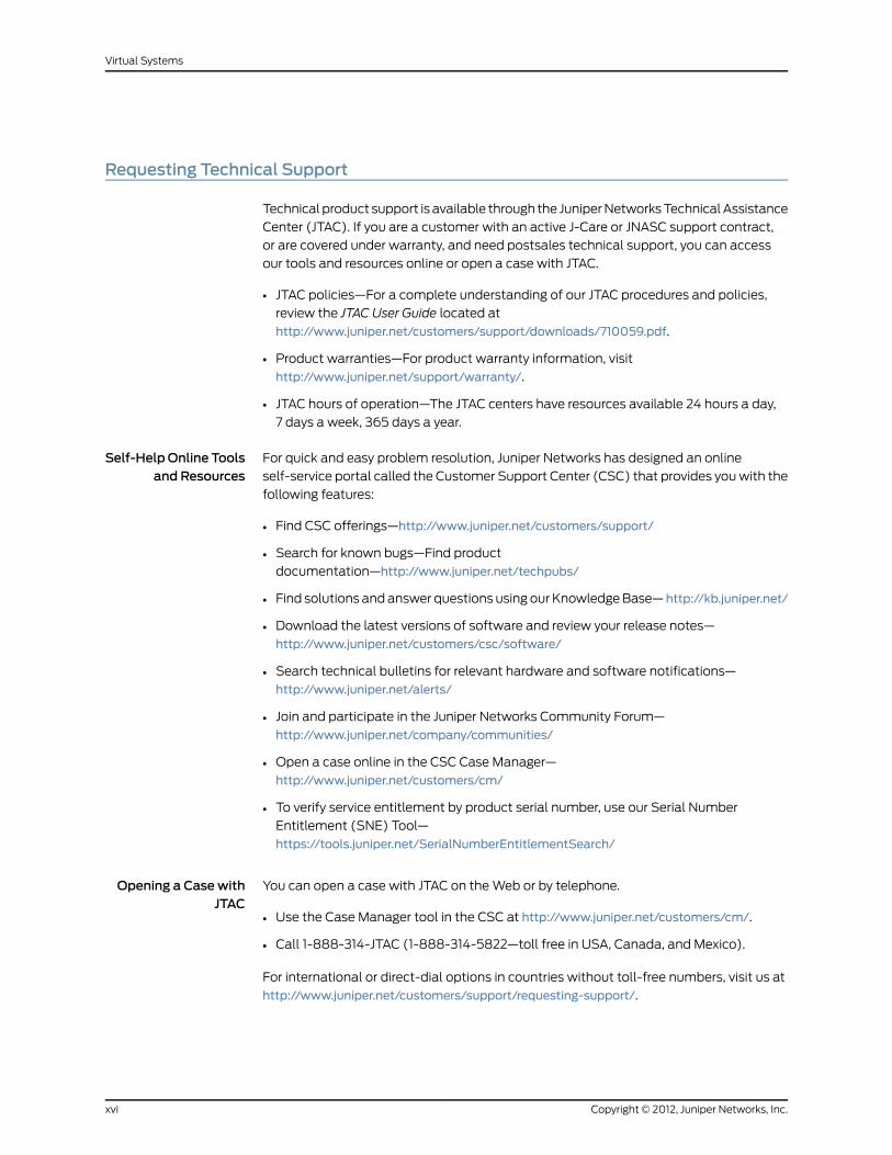
Requesting Technical Support
Technical product support is available through the Juniper Networks Technical Assistance
Center (JTAC). If you are a customer with an active J-Care or JNASC support contract,
or are covered under warranty, and need postsales technical support, you can access
our tools and resources online or open a case with JTAC.
• JTAC policies—For a complete understanding of our JTAC procedures and policies,
review the JTAC User Guide located at
http://www.juniper.net/customers/support/downloads/710059.pdf.
• Product warranties—For product warranty information, visit
http://www.juniper.net/support/warranty/.
• JTAC hours of operation—The JTAC centers have resources available 24 hours a day,
7 days a week, 365 days a year.
Self-HelpOnline Toolsand Resources
For quick and easy problem resolution, Juniper Networks has designed an online
self-service portal called the Customer Support Center (CSC) that provides you with the
following features:
• Find CSC offerings—http://www.juniper.net/customers/support/
• Search for known bugs—Find product
documentation—http://www.juniper.net/techpubs/
• Find solutions and answer questions using our Knowledge Base— http://kb.juniper.net/
• Download the latest versions of software and review your release notes—
http://www.juniper.net/customers/csc/software/
• Search technical bulletins for relevant hardware and software notifications—
http://www.juniper.net/alerts/
• Join and participate in the Juniper Networks Community Forum—
http://www.juniper.net/company/communities/
• Open a case online in the CSC Case Manager—
http://www.juniper.net/customers/cm/
• To verify service entitlement by product serial number, use our Serial Number
Entitlement (SNE) Tool—
https://tools.juniper.net/SerialNumberEntitlementSearch/
Opening a CasewithJTAC
You can open a case with JTAC on the Web or by telephone.
• Use the Case Manager tool in the CSC at http://www.juniper.net/customers/cm/.
• Call 1-888-314-JTAC (1-888-314-5822—toll free in USA, Canada, and Mexico).
For international or direct-dial options in countries without toll-free numbers, visit us at
http://www.juniper.net/customers/support/requesting-support/.
Copyright © 2012, Juniper Networks, Inc.xvi
Virtual Systems

PART 1
Virtual Systems
• Virtual Systems on page 3
• Traffic Sorting on page 35
• VLAN-Based Traffic Classification on page 45
• IP-Based Traffic Classification on page 75
1Copyright © 2012, Juniper Networks, Inc.

Copyright © 2012, Juniper Networks, Inc.2
Virtual Systems

CHAPTER 1
Virtual Systems
This chapter discusses virtual systems (vsys), objects, and administrative tasks. It contains
the following sections:
• Overview on page 3
• Vsys Objects on page 4
• Defining Identical Names for Zones Across Vsys on page 8
• Logging In as a Virtual System Admin on page 9
• Virtual System Profiles on page 10
• Sharing and Partitioning CPU Resources on page 19
• Virtual Systems and Virtual Private Networks on page 30
• Policy Scheduler on page 31
Overview
You can logically partition a single Juniper Networks security device into multiple virtual
systems (vsys) to provide multi-tenant services. Each vsys is a unique security domain
and can have its own administrators (called virtual system administratorsor vsys admins)
who can individualize their security domain by setting their own address books, user lists,
custom services, virtual private networks (VPNs), and policies. Only a root-level admin,
however, can set firewall security options, create vsys admins, and define interfaces and
subinterfaces.
NOTE: Refer to the Juniper Networksmarketing literature to see whichplatforms support the virtual system feature.
Formore informationabout thevarious levelsofadministrationthatScreenOSsupports, see Levels of Administration.
Juniper Networks virtual systems support two kinds of traffic classifications: virtual local
area network (VLAN)-based and Internet Protocol(IP)-based, both of which can function
separately or concurrently.
Table 1 on page 4 shows the interfaces a vsys can support for the Untrust and Trust
security zones:
3Copyright © 2012, Juniper Networks, Inc.

Table 1: Virtual SystemSupport
Trust Zone Interface TypesUntrust Zone Interface Types
Dedicated physical interfaceDedicated physical interface
Subinterface (with VLAN tagging)Subinterface (with VLAN tagging as a meansfor trunking inbound and outbound traffic)
Shared physical interface with root system (andIP-based traffic classification)
Shared interface (physical, subinterface,redundant interface, aggregate interface) withroot system
NOTE: For information about VLAN tagging and trunking concepts, see“VLAN-Based Traffic Classification” on page 45.
For information about IP-based traffic classification, see “IP-Based TrafficClassification” on page 75.
Figure 2 on page 4 shows how you can bind one, two, or all three of the above interface
types to a security zone concurrently. You can also bind multiple interfaces of each type
to a zone.
Figure 2: Interface and Zone Bindings with Vsys
Vsys Objects
The root admin or root-level read-write admin must complete the following tasks to
create a vsys object:
• Define a vsys.
Copyright © 2012, Juniper Networks, Inc.4
Virtual Systems

• (Optional) Define one or more vsys admins.
NOTE: A root-level admin can define, per vsys, one vsys admin withread-write privileges and one vsys admin with read-only privileges.
• Select the virtual router (VR) that you want the vsys to use for its Trust-vsysname
zone, Untrust-Tun-vsysname zone, and Global-vsysname zone.
After creating a vsys object, as the root-level admin, you need to perform other
configurations to make it functional. You must configure subinterfaces or interfaces for
the vsys, and possibly shared VRs and shared security zones. Subsequent configurations
depend on whether the vsys is intended to support VLAN-based or IP-based traffic
classifications, or a combination of both. After completing these configurations, you can
then exit the vsys and allow a vsys admin, if one is defined, to log in and begin configuring
addresses, users, services, VPNs, routes, and policies.
Creating a Virtual SystemObject and Admin
In this example, as a root-level admin, you create three vsys objects: vsys1, vsys2, and
vsys3. For vsys1, you create vsys admin Alice with password wIEaS1v1. For vsys2, you
create vsys admin Bob with password pjF56Ms2. For vsys3, you do not define a vsys
admin. Instead, you accept the admin definition that the security device automatically
generates. In the case of vsys3, the security device creates the admin “vsys_vsys3” with
password “vsys_vsys3.”
NOTE: Only a root-level admin can create a vsys admin’s profile (usernameand password). Because the security device uses usernames to determinethevsys to whichauserbelongs, vsysadminscannotchangetheirusernames.However, vsys admins can (and should) change their passwords.Virtual System names, admin names, and passwords are case-sensitive. ForExample, “Vsys abc” is different from “vsys ABC.”
For vsys1 and vsys2, you use the default VR. For vsys3, you choose the sharable root-level
untrust-vr.
After you create a vsys through the WebUI, you remain at the root level. Entering the
newly created vsys requires a separate step:
Vsys > Configure > Click Enter (for the vsys you want to enter).
The WebUI pages of the vsys you have entered appear, with the name of the vsys above
the central display area—Vsys:Name.
When you create a vsys through the CLI, you immediately enter the system that you have
just created. (To enter an existing vsys from the root level, use the enter vsys name_str
command.) When you enter a vsys, the CLI command prompt changes to include the
name of the system in which you are now issuing commands.
5Copyright © 2012, Juniper Networks, Inc.
Chapter 1: Virtual Systems
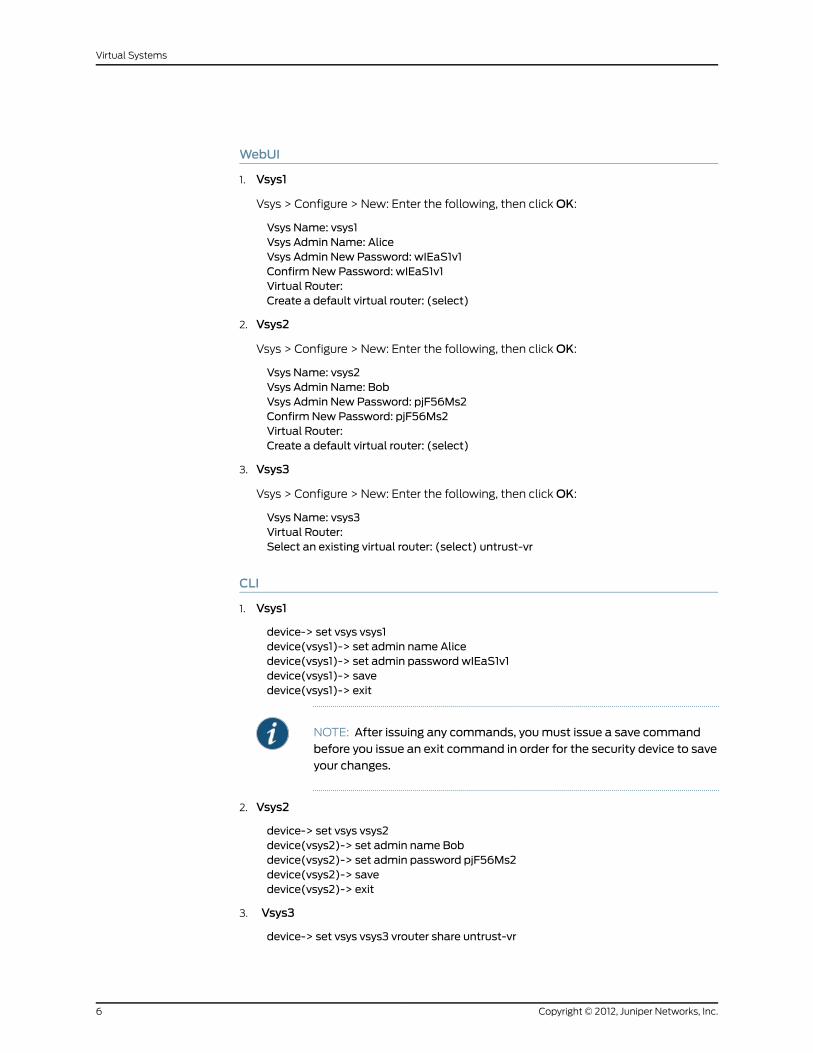
WebUI
1. Vsys1
Vsys > Configure > New: Enter the following, then click OK:
Vsys Name: vsys1Vsys Admin Name: AliceVsys Admin New Password: wIEaS1v1Confirm New Password: wIEaS1v1Virtual Router:Create a default virtual router: (select)
2. Vsys2
Vsys > Configure > New: Enter the following, then click OK:
Vsys Name: vsys2Vsys Admin Name: BobVsys Admin New Password: pjF56Ms2Confirm New Password: pjF56Ms2Virtual Router:Create a default virtual router: (select)
3. Vsys3
Vsys > Configure > New: Enter the following, then click OK:
Vsys Name: vsys3Virtual Router:Select an existing virtual router: (select) untrust-vr
CLI
1. Vsys1
device-> set vsys vsys1device(vsys1)-> set admin name Alicedevice(vsys1)-> set admin password wIEaS1v1device(vsys1)-> savedevice(vsys1)-> exit
NOTE: After issuing any commands, youmust issue a save commandbefore you issue an exit command in order for the security device to saveyour changes.
2. Vsys2
device-> set vsys vsys2device(vsys2)-> set admin name Bobdevice(vsys2)-> set admin password pjF56Ms2device(vsys2)-> savedevice(vsys2)-> exit
3. Vsys3
device-> set vsys vsys3 vrouter share untrust-vr
Copyright © 2012, Juniper Networks, Inc.6
Virtual Systems
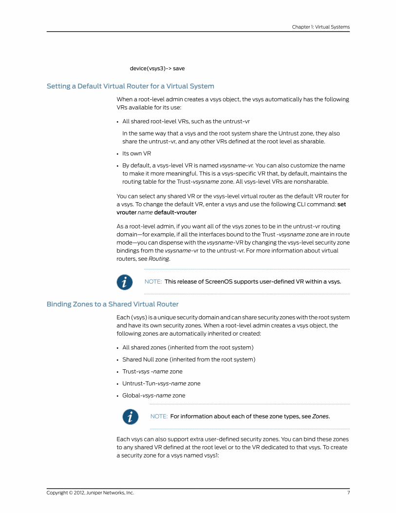
device(vsys3)-> save
Setting a Default Virtual Router for a Virtual System
When a root-level admin creates a vsys object, the vsys automatically has the following
VRs available for its use:
• All shared root-level VRs, such as the untrust-vr
In the same way that a vsys and the root system share the Untrust zone, they also
share the untrust-vr, and any other VRs defined at the root level as sharable.
• Its own VR
• By default, a vsys-level VR is named vsysname-vr. You can also customize the name
to make it more meaningful. This is a vsys-specific VR that, by default, maintains the
routing table for the Trust-vsysname zone. All vsys-level VRs are nonsharable.
You can select any shared VR or the vsys-level virtual router as the default VR router for
a vsys. To change the default VR, enter a vsys and use the following CLI command: setvrouter name default-vrouter
As a root-level admin, if you want all of the vsys zones to be in the untrust-vr routing
domain—for example, if all the interfaces bound to the Trust -vsysname zone are in route
mode—you can dispense with the vsysname-VR by changing the vsys-level security zone
bindings from the vsysname-vr to the untrust-vr. For more information about virtual
routers, see Routing.
NOTE: This release of ScreenOS supports user-defined VRwithin a vsys.
Binding Zones to a Shared Virtual Router
Each (vsys) is a unique security domain and can share security zones with the root system
and have its own security zones. When a root-level admin creates a vsys object, the
following zones are automatically inherited or created:
• All shared zones (inherited from the root system)
• Shared Null zone (inherited from the root system)
• Trust-vsys -name zone
• Untrust-Tun-vsys-name zone
• Global-vsys-name zone
NOTE: For information about each of these zone types, see Zones.
Each vsys can also support extra user-defined security zones. You can bind these zones
to any shared VR defined at the root level or to the VR dedicated to that vsys. To create
a security zone for a vsys named vsys1:
7Copyright © 2012, Juniper Networks, Inc.
Chapter 1: Virtual Systems

WebUI
Vsys > Enter (for vsys1)
Network > Zones > New: Enter the following, then click OK:
Zone Name: (type a name for the zone)Virtual Router Name: (select a VR from the drop-down list)Zone Type: Layer 3
CLI
device-> enter vsys vsys1device(vsys1)-> set zone name name_strdevice(vsys1)-> set zone vrouter vrouterdevice(vsys1)-> save
The maximum number of security zones that a vsys or the root system can contain is
limited only by the number of security zones available at the device level. It is possible
for a single vsys to consume all available security zones if the root admin or a root-level
read-write admin assigns all of the zones to that particular vsys. Conversely, if all vsys
share root-level security zones and do not make use of any user-defined vsys-level zones,
then all security zones are available for root-level use.
NOTE: The total number of user-definable (or custom ) security zonesavailable at the device level is the sum of the number of root-level customzones—as defined by one or more zone license keys—and the number ofcustom zones permitted by the vsys license key.
Defining Identical Names for Zones Across Vsys
In previous releases of ScreenOS, names you defined for the zones in a vsys had to be
unique regardless of whether the zones resided in the same or in different virtual systems.
With this release of ScreenOS, you can name zones within a vsys without regard to zone
names used in other vsys. In other words, the security device allows you to create zones
with identical names, provided these zones are defined in a different vsys and not within
the same vsys
NOTE: The name of a shared zone inherited from the root should alwaysremain unique from that of the other zones created in the vsys.
When you create a zone, the security device checks to make sure no zone with the same
name is already present within the current vsys. If the device finds a preexisting zone with
that name, it returns an error message and fails to create the zone.
The get zone zone command displays the details of the zones with identical zone names
across all vsys. Only in root vsys, you can view the list of zones that share the specified
zone name.
Copyright © 2012, Juniper Networks, Inc.8
Virtual Systems
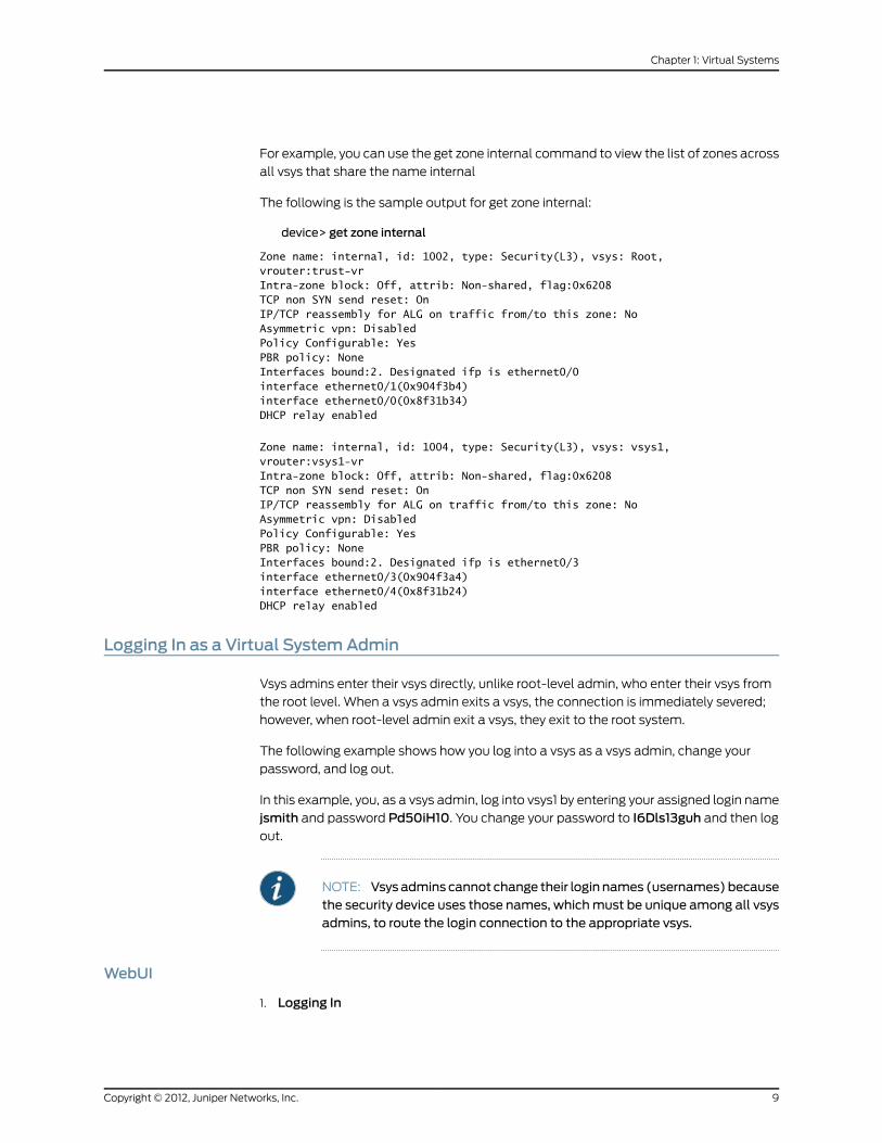
For example, you can use the get zone internal command to view the list of zones across
all vsys that share the name internal
The following is the sample output for get zone internal:
device> get zone internal
Zone name: internal, id: 1002, type: Security(L3), vsys: Root,vrouter:trust-vrIntra-zone block: Off, attrib: Non-shared, flag:0x6208TCP non SYN send reset: OnIP/TCP reassembly for ALG on traffic from/to this zone: NoAsymmetric vpn: DisabledPolicy Configurable: YesPBR policy: NoneInterfaces bound:2. Designated ifp is ethernet0/0interface ethernet0/1(0x904f3b4)interface ethernet0/0(0x8f31b34)DHCP relay enabled
Zone name: internal, id: 1004, type: Security(L3), vsys: vsys1,vrouter:vsys1-vrIntra-zone block: Off, attrib: Non-shared, flag:0x6208TCP non SYN send reset: OnIP/TCP reassembly for ALG on traffic from/to this zone: NoAsymmetric vpn: DisabledPolicy Configurable: YesPBR policy: NoneInterfaces bound:2. Designated ifp is ethernet0/3interface ethernet0/3(0x904f3a4)interface ethernet0/4(0x8f31b24)DHCP relay enabled
Logging In as a Virtual SystemAdmin
Vsys admins enter their vsys directly, unlike root-level admin, who enter their vsys from
the root level. When a vsys admin exits a vsys, the connection is immediately severed;
however, when root-level admin exit a vsys, they exit to the root system.
The following example shows how you log into a vsys as a vsys admin, change your
password, and log out.
In this example, you, as a vsys admin, log into vsys1 by entering your assigned login name
jsmith and password Pd50iH10. You change your password to I6Dls13guh and then log
out.
NOTE: Vsysadmins cannot change their login names (usernames)becausethe security device uses those names, whichmust be unique among all vsysadmins, to route the login connection to the appropriate vsys.
WebUI
1. Logging In
9Copyright © 2012, Juniper Networks, Inc.
Chapter 1: Virtual Systems

In the URL field in your browser, enter the Untrust zone interface IP address for vsys1.
When the Network Password dialog box appears, enter the following, then click OK:
User Name: jsmithPassword: Pd50iH10
2. Changing Your Password
Configuration > Admin > Administrators: Enter the following, then click OK:
Vsys Admin Old Password: Pd50iH10Vsys Admin New Password: I6Dls13guhConfirm New Password: I6Dls13guh
3. Logging Out
Click Logout, located at the bottom of the menu column.
CLI
1. Logging In
From a Secure Command Shell (SCS), Telnet, or HyperTerminal session command-line
prompt, enter the Untrust zone interface IP address for vsys1.
Log in with the following username and password:
• User name: jsmith
• Password: Pd50iH10
2. Changing Your Password
set admin password I6Dls13guhsave
3. Logging Out
exit
Virtual SystemProfiles
A root-level user (the admin for the security device) can enable or disable session and
resource limits on a per-vsys basis. If you configure a session limit for a particular vsys
and the vsys reaches or exceeds its session limits, the security device enforces the session
limit and begins dropping packets for that vsys. In the case of oversubscription, where
the total number of vsys sessions is greater than the overall number of system sessions,
you can reserve a specified number of sessions for a particular vsys. The security device
tracks packets that are dropped as a result of a session limit.
NOTE: To use virtual systems, youmust install a vsys key and then enablethis feature. It is disabled by default.
ScreenOS provides two ways to configure resource limits for a vsys:
Copyright © 2012, Juniper Networks, Inc.10
Virtual Systems

• Profile assignment
• Command overrides
Per-vsys resources for which you can define maximum and reserve limits include the
following items:
• Dynamic IP (DIP) addresses
• Mapped IP (MIP) addresses
• User-defined services and groups
• Policies and multicast policies
• Sessions
• Zone address-book entries and groups, which are per-zone per-vsys limits
• User-defined security zones
WARNING: Check with your administrator before you assign a DIP ID to avsys. Duplicate IDs used on the same device can cause dropped ormisrouted traffic. The device will not check for or prevent duplicate DIPIDs, nor will it send a notification if such duplicates exist.
NOTE: ScreenOS enforces zone address-book and zone address-grouplimits for thesharedzone,azonethatcontainsaddressandaddressgroupsfromall vsys .When viewing addresses or address groups of a shared zonefrom a vsys, only those addresses and address groups configured in thatvsys are listed. The resources used for addresses and address groups in ashared zone are charged against the root system inwhich the shared zonewas created.
You cannot reserve addresses or address groups in shared zones.
Vsys profiles can also contain CPU weights, which allow you to allocate a certain
percentage of CPU processing time for a particular vsys. See “Configuring CPU Weight”
on page 20 for more information.
Virtual SystemSession Counters
When the security device creates a new session for a particular vsys, the session counter
for that vsys increments. When the session ends, the counter decrements.
The security device counts all sessions, active and inactive, held by the vsys at any time.
Virtual SystemSession Information
The security device records session statistics for each vsys. The security device admin
(root admin) can view all of the collected statistics and session information for all virtual
11Copyright © 2012, Juniper Networks, Inc.
Chapter 1: Virtual Systems

systems. A vsys admin can view-only the sessions and statistics pertaining to that admin’s
vsys domain.
In previous ScreenOS releases, the root admin could clear vsys-specific sessions from
the security device only by clearing all sessions at the root. Beginning with the 6.2.0
release of ScreenOS, the root admin can use the clear session command to clear only
the sessions for a specific vsys.
As root admin, you can clear vsys-specific sessions in the root only when you specify the
vsys name or vsys ID as options in the clear session command. If you do not specify vsys
as the option, then only sessions pertaining to the root are deleted. If you include the
option all, all root and vsys sessions are deleted.
Use the following CLI commands to clear vsys-specific sessions:
CLI
1. Clearing Session fromRoot
clear session vsys-name vsys-name vsys-id id_numsave
2. Clearing Session from Local Vsys
clear session [ src-ip ip_addr ] [ dst-ip ip_addr ] [ src-macmac_addr ] [ dst-macmac_addr ] [ src-port port_num ] [ dst-port port_num ] [ protocol number ] [ vsd-idid_num ]
save
NOTE: Users can use the clear session command to delete sessions onlyfrom their own vsys and not different vsys.
Behavior in High-Availability Pairs
When two devices configured with NetScreen Redundancy Protocol (NSRP) are in
Active/Active mode and two sessions are simultaneously created, the result could mean
that a vsys might have one session more than the configured limit.
For more information about NSRP or Active/Active mode, see High Availability.
Creating a Vsys Profile
A vsys profile is a holder for the maximum limits and, in case of overload, specific limits
and session-only alarm thresholds that you want ScreenOS to impose on a particular
vsys or group of vsys. You can design tiered limits for services that fit the needs of your
vsys clients. For example, you can set up different classes of service, such as gold, silver,
and bronze, and assign each one different resource maximums.
Two default profiles exist:
• VsysDefaultProfile
Copyright © 2012, Juniper Networks, Inc.12
Virtual Systems

By default, when you create a new vsys, it uses the VsysDefaultProfile. By definition,
the VsysDefaultProfile allows access to all resources but does not guarantee them.
You can then re-assign a different vsys profile to the new vsys to control resource
access. You cannot edit this vsys profile.
• RootProfile
By default, the root vsys uses the RootProfile. You can configure limits in the Root
Profile to reserve certain static resources for the exclusive use of the root vsys.
You can create 18 vsys profiles in addition to the default profiles. After creating profiles,
you can assign one or more vsys to a vsys profile.
Setting Resource Limits
The global maximum value for any vsys resource depend on the security device. Vsys
uses the default values for the device if you do not explicitly set maximum and reserved
limits. To see the vsys limit values, use the get vsys vsysname command after you create
the vsys.
When setting maximum and reserved limits for resources, keep the following in mind:
• You cannot set the maximum value higher than the device-dependent global maximum
value. You can view the global maximum values by using the get vsys-profile globalcommand.
• For all resources except sessions, you cannot set the maximum value lower than the
resources currently being used (actual-use value). To view the actual-use value, use
the get vsys-profile global command.
For sessions, you can set the maximum value of sessions lower than the number of
sessions used. If you do so, no current sessions are dropped. The maximum value is
enforced when the session actual-use value falls below the maximum value, but in
the meantime, no new sessions can be created. If you use the get vsys session-limitcommand, the number of available sessions shown is a negative number.
• You cannot set the reserved value higher than the configured maximum value.
• The total allocated usage, which is the sum of reserved values or actual-use values
(whichever is higher) for all vsys, cannot exceed the global maximum value.
The following table lists how allocated usage is calculated for MIPs for three vsys (vs1,
vs2, and vs3):
Globalvs3vs2vs1
40220Reserved value(configuredvalue)
371540Actual-use
95401540Allocated usage
13Copyright © 2012, Juniper Networks, Inc.
Chapter 1: Virtual Systems

Although the actual-use value for vs3 is lower than the configured reserved value, the
reserved value is used when calculating allocated usage. The global maximum value is
95.
In the following example, you create a new vsys profile with the following settings:
• Name: gold
• CPU weight: 30 (default=50)
• DIPs: maximum: 25, reserve: 5
• MIPs: maximum: 25
• Mpolicies: maximum: 5
• Policies: maximum: 50
• Sessions: maximum: 1200
WebUI
Vsys > Profile: Select New, enter the name and desired settings, then click OK.
CLI
set vsys-profile name gold cpu-weight 30set vsys-profile gold dipsmax 25 reserve 5set vsys-profile goldmipsmax 25set vsys-profile goldmpolicies max 5set vsys-profile gold policies max 50set vsys-profile gold sessionsmax 1200save
Adding Session Limits Through Virtual-SystemProfile Assignment
You can assign a session limit to a vsys profile in the WebUI or the CLI. To set session
limits, you need to configure one or more of the following parameters:
• session max
The session maximum is a number between 100 and the maximum session number
for the overall security system. The default value is the maximum session number for
the overall security system (as if no session limitation is in force).
• reserve
In case of over-subscription, the reserve number is the number of sessions you guarantee
or reserve for the specified vsys. The reserve value is a number between zero (0) and
the maximum number of sessions you allocate for the specified vsys.
• alarm
The alarm threshold is a percentage of the maximum limit that triggers the alarm. The
default value is 100 percent of the session limit for a configured vsys.
In the following example, you configure a session limitation in a vsys profile named gold.
The desired limits are as follows:
Copyright © 2012, Juniper Networks, Inc.14
Virtual Systems

• Session max: 2500
• Reserve: 2000
• Alarm: 90 (indicates the alarm is triggered when 90 percent of the session maximum
is achieved)
A vsys that you assign to this profile can hold up to 2500 sessions at a time. When the
overall security device becomes over-subscribed only 2000 sessions are guaranteed to
the assigned vsys. At any time, if the assigned vsys consumes 90 percent of the session
maximum value an alarm is triggered.
WebUI
Vsys > Profile > Edit
CLI
set vsys-profile gold sessionmax 2500 reserve 2000 alarm 90
To assign the newly created vsys profile to a vsys named vsys1:
WebUI
Vsys > Configure > Edit
CLI
set vsys vsys1 vsys-profile name gold
Setting a Session Override
For each vsys, you can set an override for a session limit or reserve value defined in an
existing vsys profile; you can also override the alarm threshold. To do this, you first enter
the vsys and set the override. By default, no overrides exist in virtual systems.
NOTE: ScreenOS associates session overrides with a vsys and not with avsys profile.
In the following example, you set an override to allow the session maximum to be 3500
instead of 2500.
WebUI
Vsys > Configure > Edit (vsys)
CLI
enter vsys vsys1(vsys1) set override session-limit max 3500(vsys1) save
Overriding a Session Limit Reached Alarm
You can configure a session limit reached (SLR) alarm. The alarm is triggered when the
SLR level is reached or exceeded. The security device removes the alarm if the number
15Copyright © 2012, Juniper Networks, Inc.
Chapter 1: Virtual Systems

of sessions of the vsys drops below the alarm trigger level for 10 consecutive seconds.
The security device logs the alarm messages.
You can configure Simple Network Management Protocol (SNMP) traps for vsys SLR
alarms. For more information about SNMP, see Fundamentals.
In the following example, you configure an alarm to be triggered when the number of
vsys sessions is 80 percent of the session limit. The original gold profile indicates that
the alarm is triggered at 90 percent of the session limit.
WebUI
Vsys > Configure > Edit (vsys)
CLI
enter vsys vsys1(vsys1) set override session-limit alarm 80(vsys1) save
Deleting a Vsys Profile
You can delete a vsys profile in the WebUI or the CLI. Before you delete a vsys profile,
make sure that the profile is not used by any vsys. ScreenOS does not allow you to delete
a profile that is in use.
If you receive a message that a profile you want to delete is in use, change the vsys profile
of the vsys to use another profile and try to delete the profile again.
In the following example, you delete the vsys profile gold.
WebUI
Vsys > Profile: To the right of the vsys profile that you want to delete, click Remove.
CLI
unset vsys-profile gold
Viewing Vsys Settings
The admin for the security device can view the session statistics for all vsys. Within a
vsys context, however, you can view only the statistics for that particular vsys.
Viewing Overrides
To view the configured overrides for a particular vsys in the CLI, you can enter the getvsys vsysname command or the get vsys override command. You can also enter the
vsys context and then enter the get override session-limit command.
The following is sample output for get vsys vsys2:
device-> get vsys vsys2
Total number of vsys: 2
Name Id Profile Interface IP Address Vlan vsd
Copyright © 2012, Juniper Networks, Inc.16
Virtual Systems

vsys2 2 VsysDef~ N/A N/A N/AVsys-limit Maximum Reserved Actual-usedips 254 0 0mips 384 0 0mpolicies 200 0 0policies 512 0 0sessions 250064 0 0user-serv-grps 128 0 0user-servs 512 0 0user-zones 215 0 1zone-addr-grps 512 0 0(Untrust)zone-addrs 20000 4 4(Untrust)cpu-weight 50 - 0(* - The marked setting has been overridden.)
You can also view the overrides in the WebUI.
In the following example, while in a vsys context, you view the reserve for a vsys named
branch1.
WebUI
Vsys > Profile > Edit
CLI
enter vsys branch1(branch1) get override session-limit(branch1) exit
Viewing a Profile
As root admin, you can view each vsys profile with the WebUI or the CLI. From the WebUI,
you cannot view all profiles or a summary of current usage. From the CLI, as root admin,
you can view all vsys profiles and a global usage summary that includes actual use
statistics. As vsys admin, using the CLI, you can enter a vsys and view the vsys-profile
used for the vsys.
WebUI
Vsys > Profile: Select a profile to view.
CLI 1
device-> get vsys-profile red
vsys-profile-name ref-cnt vsys-limit maximum reserved peak-use---------------------------------------------------------------------------- red 0 dips 254 0 0 mips 384 0 0 mpolicies 200 0 0 policies 512 0 0 sessions 3000 100 0 user-serv-grps 128 0 0 user-servs 512 0 0 user-zones 215 0 0 zone-addr-grps 512 0 0 zone-addrs 20000 4 0 cpu-weight = 44, 29% of total cpu-weight 150 session alarm level = 100%----------------------------------------------------------------------------
17Copyright © 2012, Juniper Networks, Inc.
Chapter 1: Virtual Systems

CLI 2
device-> get vsys-profile
* indicates default vsys profile. vsys-profile-name ref-cnt vsys-limit maximum reserved peak-use-----------------------------------------------------------------------------*VsysDefaultProfile 2 dips 254 0 0 mips 384 0 0 mpolicies 200 0 0 policies 512 0 0 sessions 250064 0 0 user-serv-grps 128 0 0 user-servs 512 0 0 user-zones 215 0 1(vsys2) zone-addr-grps 512 0 0 zone-addrs 20000 4 (vsys2/Unt~) cpu-weight = 50, 33% of total cpu-weight 150 session alarm level = 100%----------------------------------------------------------------------------- RootProfile 1 dips 254 0 0 mips 6144 0 0 mpolicies 200 0 0 policies 20000 0 0 sessions 250064 0 0 user-serv-grps 128 0 0 user-servs 2048 0 0 user-zones 215 0 0 zone-addr-grps 512 0 2(Root/Tru~)
zone-addrs 20000 0 7(Root/Tru~)
cpu-weight = 50, 33% of total cpu-weight 150 session alarm level = 100%---------------------------------------------------------------------------- red 0 dips 254 0 0 mips 384 0 0 mpolicies 200 0 0 policies 512 0 0 sessions 3000 100 0 user-serv-grps 128 0 0 user-servs 512 0 0 user-zones 215 0 0 zone-addr-grps 512 0 0 zone-addrs 20000 4 0 cpu-weight = 44, 29% of total cpu-weight 150 session alarm level = 100%----------------------------------------------------------------------------global usage summary: global-limit maximum allocated actual use use---------------------------------------------------------------------------- dips 65535 0 0 mips 6145 0 0 mpolicies 200 0 0 policies 20000 0 0 sessions 250064 0 0 user-serv-grps 128 0 0 user-servs 2048 0 0 user-zones 215 1 1 zone-addr-grps 512 2 2
Copyright © 2012, Juniper Networks, Inc.18
Virtual Systems

zone-addrs 20000 95 75 total cpu-weight = 150
NOTE: The peak-use value is the highest value among all vsys using a vsysprofile.
Viewing Session Statistics
To view session statistics, enter the vsys context, then enter the get session command.
WebUI
Not available.
CLI
(vsys1)-> get sessionvsys1: sw alloc 0/max 3500, alloc failed 0, mcast alloc 0Total 0 sessions shown(vsys1)->
Sharing and Partitioning CPU Resources
By default, all vsys within a single security system share the same CPU resources. It is
possible for one virtual system (vsys) to consume excess CPU resources at the expense
of other vsys.
For example, if one vsys , within a security system that houses 20 vsys , experiences a
denial of service(DOS) attack that consumes all of the CPU resources, the CPU is unable
to process traffic for any of the other 19 vsys. In essence, all 20 vsys experience the DOS
attack. CPU overutilization protection, also known as the CPU limit feature, is intended
to protect against this.
Overutilization protection allows you to configure the security device for fair use, or Fair
mode, as opposed to shared use, or Shared mode. To enable a fairer distribution of
processing resources, you can assign a flow CPU utilization threshold to trigger a transition
to Fair mode, and you can choose a method for transition back to Shared mode. By
default, the security device operates in Shared mode.
To enforce fair use, you assign a CPU weight to each vsys that you configure. ScreenOS
uses these weights, relative to the weights of all vsys in the security device, to assign time
quotas proportional to those weights. ScreenOS then enforces the time quotas over
one-second intervals. This means that as long as a vsys does not exceed its time quota
over that one-second period and the firewall is not too heavily loaded, no packets for
that vsys should be dropped.
NOTE: The CPU overutilization protection feature is independent of thesession limits imposed by a vsys profile.
19Copyright © 2012, Juniper Networks, Inc.
Chapter 1: Virtual Systems
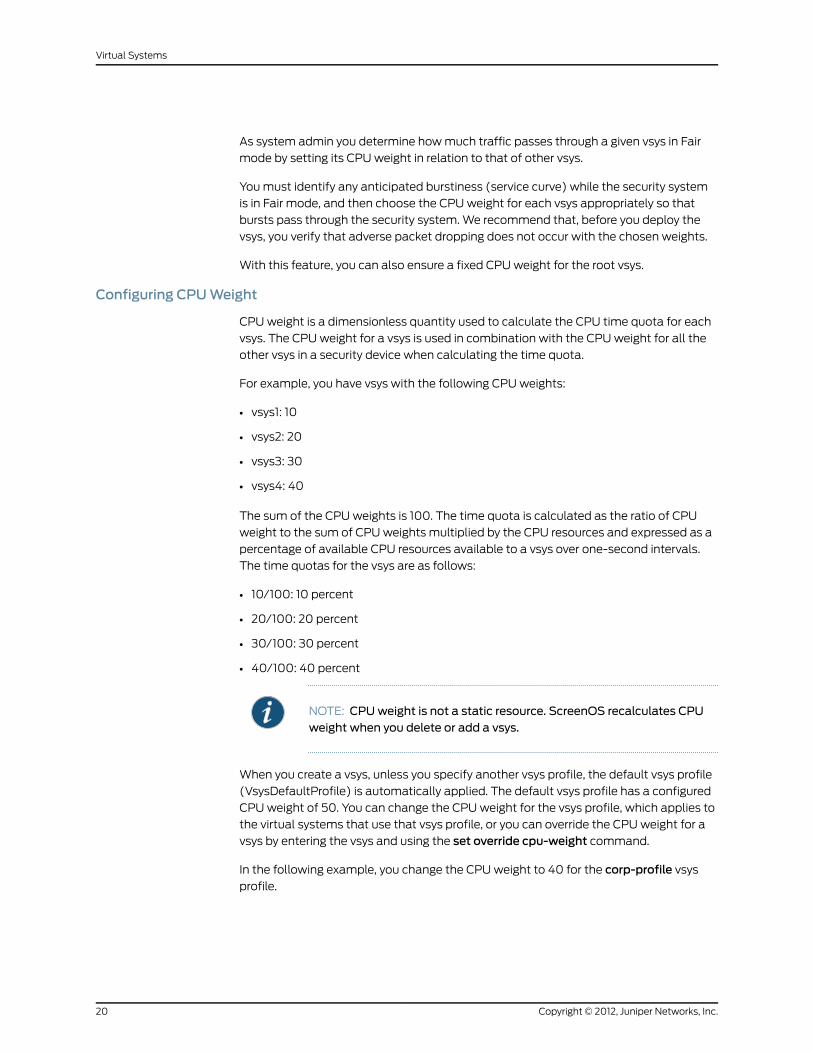
As system admin you determine how much traffic passes through a given vsys in Fair
mode by setting its CPU weight in relation to that of other vsys.
You must identify any anticipated burstiness (service curve) while the security system
is in Fair mode, and then choose the CPU weight for each vsys appropriately so that
bursts pass through the security system. We recommend that, before you deploy the
vsys, you verify that adverse packet dropping does not occur with the chosen weights.
With this feature, you can also ensure a fixed CPU weight for the root vsys.
Configuring CPUWeight
CPU weight is a dimensionless quantity used to calculate the CPU time quota for each
vsys. The CPU weight for a vsys is used in combination with the CPU weight for all the
other vsys in a security device when calculating the time quota.
For example, you have vsys with the following CPU weights:
• vsys1: 10
• vsys2: 20
• vsys3: 30
• vsys4: 40
The sum of the CPU weights is 100. The time quota is calculated as the ratio of CPU
weight to the sum of CPU weights multiplied by the CPU resources and expressed as a
percentage of available CPU resources available to a vsys over one-second intervals.
The time quotas for the vsys are as follows:
• 10/100: 10 percent
• 20/100: 20 percent
• 30/100: 30 percent
• 40/100: 40 percent
NOTE: CPUweight is not a static resource. ScreenOS recalculates CPUweight when you delete or add a vsys.
When you create a vsys, unless you specify another vsys profile, the default vsys profile
(VsysDefaultProfile) is automatically applied. The default vsys profile has a configured
CPU weight of 50. You can change the CPU weight for the vsys profile, which applies to
the virtual systems that use that vsys profile, or you can override the CPU weight for a
vsys by entering the vsys and using the set override cpu-weight command.
In the following example, you change the CPU weight to 40 for the corp-profile vsys
profile.
Copyright © 2012, Juniper Networks, Inc.20
Virtual Systems

WebUI
Vsys > CPU Limit: Click Edit for the corp-profile vsys profile, type 40 in the CPU Weight
field, and click OK.
CLI
set vsys-profile corp-profile cpu-weight 40
Fair Mode Packet Flow
If you enable overutilization protection and the security device becomes heavily loaded,
ScreenOS transitions the device to Fair mode.
While in Fair mode, ScreenOS processes a packet as follows:
1. The system allocates resources for the packet and timestamps it.
2. The flow CPU processes the packet.
3. The system determines the vsys against which the packet should be charged and the
time-quota balance of that vsys. If the vsys is over its time quota, the system drops
the packet. See Table 2 on page 21 to see how ScreenOS determines which vsys to
charge.
4. After the system processes the packet, the system computes the CPU processing
time for the packet from the current time and timestamp from step 1. The system
then charges the amount against the remaining time quota for the vsys.
When the time quota of a vsys is exhausted, the ScreenOS drops all subsequent packets
for that vsys.
Table 2: Determining Charged Vsys
Charged VsysDestination VsysSource Vsys
RootRootRoot
Destination vsysDestination vsysRoot
Source vsysRootSource vsys
Source vsysDestination vsysSource vsys
NOTE: This packet dropping (enforcement) is done only in Fair mode.
The ScreenOS refreshes time quotas every 125 milliseconds.
21Copyright © 2012, Juniper Networks, Inc.
Chapter 1: Virtual Systems

NOTE: CPU overutilization protection is performed solely by the flow CPUwith no hardware support. This feature provides a best effort to processpackets of vsys that are not over their time quotas. There is no guarantee,however, that each vsys cannot usemore than its assigned time quota, as ittakes time to determine the appropriate vsys against which packets arecharged.
The time required to drop packets for a vsys that is over its time quota is alsocharged to that vsys. If a vsys is receiving heavy traffic and is consistentlyover its time quota, no packets can pass through the system for that vsys.
However, on Juniper Networks security devices that support blacklisting ofDoS attack traffic, the device drops the packet, based on the blacklist thatyou configure. In addition, such platforms support prioritizing the traffic inhigh-CPU utilization situations such as a DoS attack to ensure that criticaltraffic is not affected even though noncritical traffic may be dropped. Onsuch devices, these features are implemented on the entire device, not on avirtual system basis. For more information about device-based trafficblacklisting, see CPU Protection with Blacklisting DoS Attack Traffic andPrioritizing Critical Traffic.
Returning from Fair Mode to SharedMode
Depending on how a root admin configures the security device, ScreenOS takes one of
the following actions:
• Remains in Fair mode until an admin explicitly configures the security device to Shared
mode.
• Returns to Shared mode after a specific time limit.
Return to Shared mode automatically after the projected flow CPU utilization falls below
a configured threshold.
Enabling the CPU Limit Feature
Before you can use many of the CPU limit commands in the CLI, you must first initialize
and allocate resources for the feature. After configuring the CPU limit parameters using
the CLI, you then must enable the feature.
WebUI
Vsys > CPU Limit: Select the CPU Limit Enable check box, then click OK.
CLI
To initialize and allocate resources for the CPU limit feature:
set cpu-limit
After configuring the CPU limit parameters, to enable the feature:
Copyright © 2012, Juniper Networks, Inc.22
Virtual Systems

set cpu-limit enable
To disable the feature:
unset cpu-limit enable
To disable the feature and deallocate resources:
unset cpu-limit
Measuring CPUUsage
Each security device measures how many CPU cycles have passed. Using the CPU weights
for each vsys within a security device, you can assign a resource quota to each vsys.
To determine the current CPU usage for a security system, log in as the root admin and
use the get performance cpu-limit or get vsys cpu-limit command. These commands
return a per-vsys breakdown of the percentage of CPU usage in terms of the percentage
of CPU time quota assigned to each vsys.
NOTE: Before you can use these commands, youmust enable the CPU limitfeature by using the set cpu-limit enable command. For more informationabout this command, refer to the ScreenOS CLI Reference Guide: IPv4Command Descriptions.
The following output for a security device with Fair mode enabled shows a total of six
configured vsys (five vsys plus the root vsys):
CPU Quota %Vsys Name Wgt Cfg % 1 min 5 min 15 minRoot 50 16.6 0 0 0corp 50 16.6 99 99 99 v1 50 16.6 8 18 10v2 50 16.6 8 18 10v3 50 16.6 7 17 9v4 50 16.6 7 17 13
The output lists the following details:
• Vsys Name
• Wgt—configured CPU weight for this vsys
• Cfg %—configured percentage of CPU resources for this vsys
• 1 min—percentage of CPU quota used by this vsys in the last minute
• 5 min—percentage of CPU quota used by this vsys in the last 5 minutes
• 15 min—percentage of CPU quota used by this vsys in the last 15 minutes
In the previous example, of the configured vsys, vsys corp used almost all of its CPU time
quota in the last minute, last 5 minutes, and last 15 minutes. Except for the root vsys,
which used no CPU resources, the other vsys used 7 to 8 percent of their CPU time quotas
in the last minute and 17 to 18 percent of their CPU time quotas in the last 5 minutes.
23Copyright © 2012, Juniper Networks, Inc.
Chapter 1: Virtual Systems

To look at detailed packet data for a vsys, use the get performance cpu-limit detail vsysall vsysname command. This command returns statistics for the specified vsys over the
last 60 seconds and last 60 minutes.
The following output shows the following information:
• Number of packets successfully passed
• Number of dropped packets
• CPU quota in percentages
device-> get performance cpu-limit detail vsys corpvsys corp: Last 60 seconds (paks passed,paks dropped by cpu limit/cpu quota %):59: 916, 10550/78 58: 1206, 13796/99 57: 1252, 13751/99 56: 1255, 13747/99 55: 1302, 13700/99 54: 1308, 13694/99 53: 1337, 13666/99 52: 1232, 13770/99 51: 1222, 13780/99 50: 1263, 13740/99 49: 1322, 13680/99 48: 1311, 13691/99 47: 1334, 13668/99 46: 1317, 13686/99 45: 1319, 13683/99 44: 1322, 13680/99 43: 1333, 13670/99 42: 1323, 13679/99 41: 1337, 13665/99 40: 1333, 13670/99 39: 1331, 13671/99 38: 1325, 13678/99 37: 1318, 13685/99 36: 1319, 13683/99 35: 1318, 13685/99 34: 1333, 13668/99 33: 1355, 13647/99 32: 1346, 13656/99 31: 1360, 13642/99 30: 1360, 13643/99 29: 1351, 13651/99 28: 1346, 13656/99 27: 1357, 13646/99 26: 1339, 13663/99 25: 1337, 13665/99 24: 1356, 13646/99 23: 1329, 13674/99 22: 7190, 6961/99 21: 13164, 0/ - 20: 13219, 0/ - 19: 13765, 0/ - 18: 15136, 0/ - 17: 7730, 0/ - 16: 200, 0/ - 15: 200, 0/ - 14: 200, 0/ - 13: 200, 0/ - 12: 200, 0/ - 11: 200, 0/ - 10: 200, 0/ - 9: 200, 0/ - 8: 200, 0/ - 7: 200, 0/ - 6: 200, 0/ - 5: 200, 0/ - 4: 200, 0/ - 3: 200, 0/ 7 2: 648, 5566/47 1: 1317, 13685/99 0: 1333, 13670/99
Last 60 minutes (paks passed,paks dropped by cpu limit):59: 77968, 471526 58: 85666, 537590 57: 33921, 523433 56: 21110, 564548 55: 80572, 748114 54: 91814, 538566 53: 83932, 544342 52: 72268, 624337 51: 1339, 708070 50: 87790, 970630 49: 96317, 1084226 48: 68805, 267087 47: 0, 0 46: 0, 0 45: 0, 0 44: 0, 0 43: 0, 0 42: 0, 0 41: 1, 0 40: 0, 0 39: 0, 0 38: 0, 0 37: 0, 0 36: 0, 0 35: 0, 0 34: 0, 0 33: 0, 0 32: 0, 0 31: 0, 0 30: 0, 0 29: 0, 0 28: 0, 0 27: 0, 0 26: 0, 0 25: 0, 0 24: 0, 0 23: 0, 0 22: 0, 0 21: 1, 0 20: 0, 0 19: 0, 0 18: 0, 0 17: 0, 0 16: 0, 0 15: 0, 0 14: 0, 0 13: 0, 0 12: 0, 0 11: 0, 0 10: 90714, 679865 9: 86549, 1478569 8: 88999, 1429512 7: 238258, 566208 6: 316219, 479793 5: 477711, 0 4: 376981, 0 3: 439035, 0 2: 395397, 735399 1: 87908, 743423 0: 0, 0
Copyright © 2012, Juniper Networks, Inc.24
Virtual Systems

This output shows that in the last 60 seconds, the corp vsys exceeded its assigned CPU
quota from second 0 until second 2 and from second 22 to second 59, with an
approximate average packet drop rate of over 10,000 packets per second.
For instance, at second 1,1,317 packets were passed, but 13,685 packets were dropped,
because the corp vsys went over its assigned CPU quota. From second 3 until second 16,
the corp vsys passed 200 packets per second, and the security device returned to Shared
mode (ScreenOS outputs "-" in the % CPU quota column when in Shared mode). At
second 22, the system reentered Fair mode.
As root admin, you have several options for the level of detail when viewing CPU utilization
statistics. See Table 3 on page 25.
Table 3: Get CommandOptions for CPUUtilization Protection
PurposeCommand
Returns CPU weights and corresponding CPU time quotapercentages and CPU quota percentages for all vsys.
get performance cpu-limit
Returns detailed statistics collected over the last 60 secondsand 60 minutes for the specified vsys.
get performance cpu-limitdetail vsys vsysname
Returns the flow CPU utilization or the projected flow CPUutilization over the last 60 seconds:
• When the device is in Shared mode, the number displayed isthe flow CPU utilization.
• When the device is in Fair mode, the number displayed is theprojected flow CPU utilization.
Use to determine the shared-to-fair, fair, and fair-to-sharedautomatic thresholds.
Asterisk to the right of the number indicates that the devicewas in Fair mode at that time.
Utilization shown using this command is 8 to 12 percent lowerthan the output shown using the get performance cpucommand, because the get cpu-limit utilization commanddoes not include some overhead values.
get cpu-limit utilization
Shows the same output as the get performance cpu-limitcommand.
get vsys cpu-limit
Detailed Session Scan Debugging
You can get detailed statistics about a task using the task debug command. To do this,
you set the debug option on a task, and then get the task details.
PurposeCommand
Sets the debug option on the specified task.set task task-name | task-iddebug
25Copyright © 2012, Juniper Networks, Inc.
Chapter 1: Virtual Systems

PurposeCommand
Returns the subtask details of the specified task.
• Runtime: Subtask's CPU time consumption (in seconds)
• Name: Subtask name
• RunCnt: Number of times the subtask has been run
• Schedule: Number of times the subtask was paused andresumed
• LockLatency: Time spent by the CPU in resolving reservationof exclusive access for resources for a CPU in multi-CPUplatforms
get task task-id
Setting the Shared-to-Fair Mode CPUUtilization Threshold
Perform the following steps to set a security system to transition from Shared mode (the
default) to Fair mode in order to protect CPU resource availability for other vsys. You
might have to repeat portions of this procedure until you are satisfied with the settings
and have verified their effectiveness.
You can set the CPU utilization threshold in the WebUI or the CLI. The WebUI example
is a summary of the command choices. The steps in the CLI example are complete.
NOTE: The flow CPU utilization, as configured by the CPU limit feature, iscalculateddifferently fromtheoutputof thegetperformancecpucommand.To set the shared-to-fair threshold, use one of the following procedures.
WebUI
Vsys > CPU Limit: Select the CPU Limit Enable check box, then click OK.
Fair to Shared: Select how or if you want the security device to return to Sharedmode.If you select Automatic, enter a threshold. If you select Fair Time, which is an explicitnumber of seconds for the device to use Fairmode, enter the desired number of seconds.Shared to Fair: Enter a threshold, then enter a hold-down time (optional).
CLI
1. Verify that the device is not processing traffic.
2. To initialize the CPU limit feature:
set cpu-limit
3. The shared-to-fair-threshold setting indicates the threshold above which the security
device transitions from Shared mode to Fair mode.
You can also optionally set a hold-down time, which is the minimum amount of time
the CPU usage exceeds the specified shared-to-fair threshold at which the security
mode enters Fair mode.
Copyright © 2012, Juniper Networks, Inc.26
Virtual Systems

To set the shared-to-fair-thresholdandhold-downtime (optional), enter a threshold
value (a number from 1 to 100) and a hold-down time (a value from 0 through 1800
seconds):
set cpu-limit shared-to-fair threshold threshold [hold-down-time number]
4. To enable the CPU limit, enter the following command:
set cpu-limit enable
5. To verify the current mode and other CPU limit parameters:
get cpu-limit
device-> get cpu-limit Current mode: shared Shared->fair: threshold 80%, hold down time 1 Fair->shared: automatic, threshold 70% CPU limit: enabled
6. Send traffic at a level that should keep the device in Shared mode.
7. To verify that the security system stays in Shared mode:
get cpu-limit utilization
Sample output:
device-> get cpu-limit utilization Last 60 seconds: 59: 14 58: 14 57: 14 56: 14 55: 14 54: 14 53: 14 52: 15 51: 14 50: 14 49: 14 48: 15 47: 14 46: 15 45: 14 44: 15 43: 14 42: 15 .... [output continues]
If asterisks appear in the output after the traffic is started, the device is in Fair mode,
and the shared-to-fair threshold is too low. Perform the following steps:
a. Stop traffic.
b. Raise the shared-to-fair threshold with the set cpu-limit shared-to-fair thresholdflow_threshold command.
c. To force the security system to return to Shared mode:
exec cpu-limit mode shared
d. Restart traffic and repeat step 7 as necessary.
8. Increase the traffic to a level that should force the device to transition to Fair mode.
9. To verify that the security system transitioned to Fair mode:
get cpu-limit utilization
device-> get cpu-limit utilizationLast 60 seconds: 59: 96* 58: 94* 57: 96* 56: 96* 55: 96* 54: 82* 53: 20 52: 14 51: 15 50: 14 49: 15 48: 14 47: 14 46: 14 45: 14 44: 14 43: 14 42: 14 41: 15 40: 14 39: 15 38: 15 37: 15 36: 14 35: 15 34: 14 33: 14 32: 14 31: 15 30: 14 29: 14 28: 14 27: 15 26: 15 25: 15 24: 15 23: 91* 22: 96* 21: 97* 20: 96* 19: 97* 18: 96*
27Copyright © 2012, Juniper Networks, Inc.
Chapter 1: Virtual Systems

17: 97* 16: 96* 15: 98* 14: 96* 13: 98* 12: 96* 11: 98* 10: 96* 9: 97* 8: 96* 7: 97* 6: 96* 5: 97* 4: 96* 3: 97* 2: 96* 1: 97* 0: 96* (* - In Fair mode; projected CPU utilization displayed.)
If the system is not in Fair mode after the traffic is increased, the shared-to-fair
threshold is set too high. Follow these steps:
a. Stop the traffic.
b. Lower the shared-to-fair threshold by entering the set cpu-limit shared-to-fairthreshold flow_threshold command.
NOTE: You can use the get cpu-limit utilization command as a guide.
c. Restart the traffic and repeat step 9 until the threshold is correct.
Configuring aMethod for Returning to SharedMode
After setting the shared-to-fair CPU utilization threshold, you can configure the device
to transition to Shared mode automatically, transition to Shared mode after an explicit
period, or stay in Fair mode.
• To configure automatic transition to Shared mode, you configure a threshold value for
the security device. The threshold is the projected flow CPU utilization value below
which the security device transitions from Fair-to-Shared mode. You can also configure
a hold-down time, which is the minimum amount of time that the flow CPU utilization
percentage must exceed the flow CPU utilization percentage threshold.
• To configure an explicit period, set the security device to use Fair mode with a fair time
setting. The fair time can be between zero (0) and 7200 seconds.
• To maintain Fair mode, select never.
In the following example, logged in as the root admin, you configure the security device
to automatically revert back to Shared mode after the projected flow CPU utilization
falls below a specific threshold.
In this example, assume that you are setting the fair-to-shared CPU utilization threshold
for the first time, so you might have to repeat the steps to try different settings before
the device behaves as you expect it to. Verification steps are included. The example
shows the CLI commands.
NOTE: This procedure is necessary only if youwant to enable Fair Automaticmode.
WebUI
Vsys > CPU Limit: Select the CPU Limit Enable check box, then click OK.
Copyright © 2012, Juniper Networks, Inc.28
Virtual Systems

Fair to Shared: Select how or if you want the security device to return to Sharedmode.If you select Automatic, enter a threshold.
CLI
1. Verify that traffic is arriving at the security device at a level that keeps the device in
Fair mode.
2. To set the Fair Automatic threshold:
set cpu-limit fair-to-shared automatic threshold number
3. Lower the traffic rate to a level that should trigger the device to return to Shared mode.
4. To Verify that the device returns to Shared mode enter the get cpu-limit utilizationcommand.
5. If the device is still in Fair mode, repeat all steps in this procedure using a lower value
for the fair automatic threshold.
Setting a Fixed Root Vsys CPUWeight
To specify an explicit CPU percentage for the root vsys, you can calculate the root vsys
CPU weight. However, when you add or delete a vsys, you have to recalculate the root
vsys CPU weight.
To ensure that the calculated root vsys CPU weight is correct, you must configure the
CPU weights of all other vsys. Then use the following formula to compute the required
root vsys CPU weight:
R=PW/(1–P)
where:
• R is the root vsys CPU weight
• P is the proportion of the CPU desired for root vsys, where:
• W is the sum of the weights of all the other vsys.
In the following example, you want to assign 30 percent of the CPU resources to the root
vsys when you have four vsys distributed among three vsys profiles, as follows:
• Gold profile (CPU weight = 40): 1 vsys
• Silver profile (CPU weight = 30): 2 vsys
• RootProfile: 1 root vsys
The sum of the CPU weights of all vsys excluding the root vsys (W) is 100. The percentage
(P) you want to assign to the root vsys is 30 percent or .3.
Using the previous equation: R=P*W/(1-P) = .3*100/.7=43
To check, the root vsys percentage is 43/(100+43), which yields approximately 30 percent.
29Copyright © 2012, Juniper Networks, Inc.
Chapter 1: Virtual Systems

If you add or delete a vsys in the future, you must redetermine W and recalculate the root
vsys CPU weight R.
Virtual Systems and Virtual Private Networks
The root vsys admin can view the following virtual private network (VPN) information:
• All configured or only active security associations (SAs)
• Internet Key Exchange (IKE) cookies
Read-write and read-only vsys admins can see the information that pertains only to their
vsys.
The next sections explain more about this information and how to view it.
Viewing Security Associations
If you are the root system admin for the security device, you can view the SAs for all vsys
by entering the get sa command. When you issue this command, you retrieve the total
number of IPsec SAs stored in the security device, which is the root system plus all
configured vsys.
WebUI
VPNs > Monitor Status
CLI
get sa
If you are a vsys admin and are using the CLI, you can view the SAs that are applicable
to your particular vsys by entering a vsys context and then entering the get sa command.
To view only the active SAs, enter the get sa active command.
In the following example, as vsys admin for clothing_store, you can view only the active
SAs for your vsys.
WebUI
VPNs > Monitor Status
CLI
enter vsys clothing_store(clothing_store) get sa active(clothing_store) exit
Viewing IKE Cookies
You can view IKE cookies from the CLI only.
As system admin for the security device, you can view all of the IKE cookies for the system,
which is the root plus the vsys IKE cookies. You can view them from the CLI by entering
the get ike cookie command.
Copyright © 2012, Juniper Networks, Inc.30
Virtual Systems

In the following example, as system admin, you view the IKE cookies.
WebUI
Not available.
CLI
get ike cookie
As a vsys admin, you can view the IKE cookies for the vsys you manage by entering the
vsys context and then entering the get ike cookie command.
In the following example, you view the IKE cookies for the vsys you manage, card_shop.
WebUI
Not available.
CLI
enter vsys card_shop(card_shop) get ike cookie(card_shop) exit
Policy Scheduler
Within a vsys context, a vsys admin can schedule a single or recurrent timeslot within
which a policy is active.
When a new policy is created, a vsys admin can create a scheduler and then bind it to
one or more existing policies. The session ages out when the scheduler times out.
This section explains the following tasks:
• “Creating a Policy Scheduler” on page 31
• “Binding a Policy Schedule to a Policy” on page 32
• “Viewing Policy Schedules” on page 32
• “Deleting a Policy Schedule” on page 33
Creating a Policy Scheduler
As a vsys admin, you can schedule a policy to be active for one time only or on a recurrent
basis. You can configure a meaningful name and a start and stop time for the scheduler.
You can also attach comments.
In the following example, you configure a scheduler for a recurring service restriction from
Monday to Friday from 8:00 to 11:30 AM and from 1:00 to 5:00 PM. The scheduler sets
the time restrictions; the policy sets the service restriction. You enter a vsys context and
perform the configuration in the vsys context.
WebUI
Vsys > Configure > Enter
31Copyright © 2012, Juniper Networks, Inc.
Chapter 1: Virtual Systems

Objects > Schedules > Click New and fill in the schedule form, then click OK.
CLI
device(hr)-> set scheduler restrictionM recurrent monday start 8:00 stop 11:30 start13:00 stop 17:00device(hr)-> set scheduler restrictionTu recurrent tuesday start 8:00 stop 11:30 start13:00 stop 17:00device(hr)-> set scheduler restrictionW recurrent wednesday start 8:00 stop 11:30 start13:00 stop 17:00device(hr)-> set scheduler restrictionTh recurrent thursday start 8:00 stop 11:30 start13:00 stop 17:00device(hr)-> set scheduler restrictionF recurrent friday start 8:00 stop 11:30 start 13:00stop 17:00device(hr)-> save
Binding a Policy Schedule to a Policy
You can attach a scheduler to a policy as you create the policy, or you can bind the
scheduler later in the WebUI.
In this example, you configure a new policy from Trust to Untrust and set the source and
destination address-book entries.
WebUI
Vsys > Configure > Enter
Policies: Select the zones, then click New. After configuring the policy, click Advanced:
At the bottom of the page, select the schedule from the drop-down list, then click OK.
CLI
device(hr)-> set policy id 1 from trust to untrust company any http deny schedulerestrictionMdevice(hr)-> set policy id 1 from trust to untrust company any http deny schedulerestrictionTudevice(hr)-> set policy id 1 from trust to untrust company any http deny schedulerestrictionWdevice(hr)-> set policy id 1 from trust to untrust company any http deny schedulerestrictionThdevice(hr)-> set policy id 1 from trust to untrust company any http deny schedulerestrictionFdevice(hr)-> save
Viewing Policy Schedules
To view configured schedules:
WebUI
Vsys > Configure > Enter
Objects > Schedules
Copyright © 2012, Juniper Networks, Inc.32
Virtual Systems

CLI
device(hr)-> get scheduler
Deleting a Policy Schedule
In the following example, as a vsys admin, you delete the schedule named restrictionW.
WebUI
Vsys > Configure > Enter
Objects > Schedules: Click Remove.
CLI
device(hr)-> unset scheduler restrictionW
33Copyright © 2012, Juniper Networks, Inc.
Chapter 1: Virtual Systems

Copyright © 2012, Juniper Networks, Inc.34
Virtual Systems
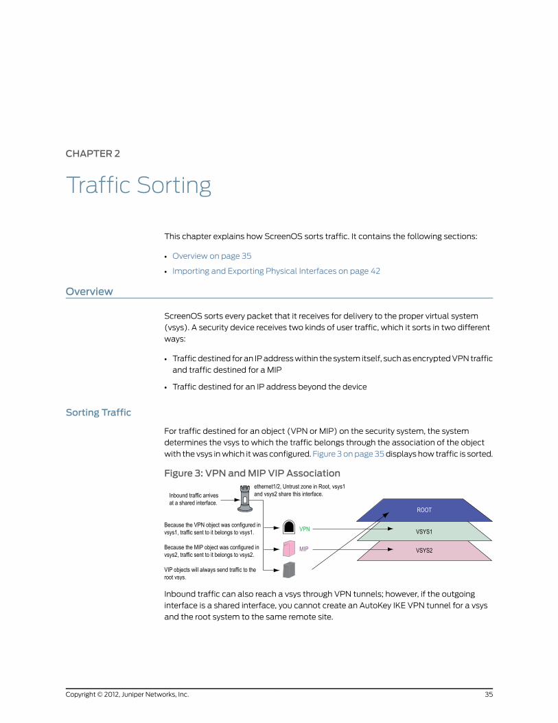
CHAPTER 2
Traffic Sorting
This chapter explains how ScreenOS sorts traffic. It contains the following sections:
• Overview on page 35
• Importing and Exporting Physical Interfaces on page 42
Overview
ScreenOS sorts every packet that it receives for delivery to the proper virtual system
(vsys). A security device receives two kinds of user traffic, which it sorts in two different
ways:
• Traffic destined for an IP address within the system itself, such as encrypted VPN traffic
and traffic destined for a MIP
• Traffic destined for an IP address beyond the device
Sorting Traffic
For traffic destined for an object (VPN or MIP) on the security system, the system
determines the vsys to which the traffic belongs through the association of the object
with the vsys in which it was configured. Figure 3 on page 35 displays how traffic is sorted.
Figure 3: VPN andMIP VIP Association
Inbound traffic can also reach a vsys through VPN tunnels; however, if the outgoing
interface is a shared interface, you cannot create an AutoKey IKE VPN tunnel for a vsys
and the root system to the same remote site.
35Copyright © 2012, Juniper Networks, Inc.

Sorting Through Traffic
For traffic destined for an IP address beyond the security device (also known as “through
traffic”), the device uses techniques made possible by VLAN-based and IP-based traffic
classifications. VLAN-based traffic classification uses VLAN tags in frame headers to
identify the system to which inbound traffic belongs. IP-based traffic classification uses
the source and destination IP address in IP packet headers to identify the system to which
traffic belongs. The process that the security device uses to determine the system to
which a packet belongs progresses through the following three steps:
NOTE: VLAN tagging requires the use of subinterfaces. A subinterfacemustbe dedicated to a system, in contrast to a shared interface, which is sharedby all systems.
1. Ingress Interface/Source IP Traffic Classification
The security device checks if the ingress interface is a dedicated interface or a shared
interface.
NOTE: For more information about shared and dedicated interfaces, see“Dedicated and Shared Interfaces” on page 40.
a. If the ingress interface is dedicated to a vsys (“v-i”, for example), the security device
associates the traffic with the system to which the interface is dedicated.
b. If the ingress interface is a shared interface, the security device uses IP classification
to check if the source IP address is associated with a particular vsys. See Figure 4
on page 37.
• If the source IP address is not associated with a particular vsys, ingress IP
classification fails.
• If the source IP address is associated with a particular vsys, ingress IP
classification succeeds.
Copyright © 2012, Juniper Networks, Inc.36
Virtual Systems

Figure 4: Step 1—Ingress Interface and Source IP Traffic Classification
2. Egress Interface/Destination IP Traffic Classification
The security device checks if the egress interface is shared or dedicated.
a. If the egress interface is dedicated to a vsys (“v-e”, for example), the security device
associates the traffic with the system to which the interface is dedicated. Note
that VIP traffic on an untrust interface will always be routed to the root vsys.
b. If the egress interface is a shared interface, the security device uses IP classification
to check if the destination IP address is associated with a particular vsys. See Figure
5 on page 38.
• If the destination IP address is not associated with a particular vsys, egress IP
classification fails.
• If the destination IP address is associated with a particular vsys, egress IP
classification succeeds.
37Copyright © 2012, Juniper Networks, Inc.
Chapter 2: Traffic Sorting
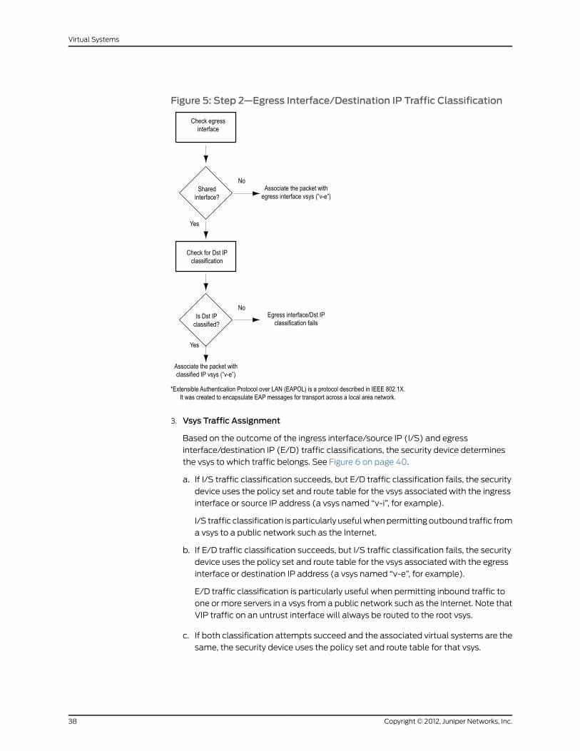
Figure 5: Step 2—Egress Interface/Destination IP Traffic Classification
3. Vsys Traffic Assignment
Based on the outcome of the ingress interface/source IP (I/S) and egress
interface/destination IP (E/D) traffic classifications, the security device determines
the vsys to which traffic belongs. See Figure 6 on page 40.
a. If I/S traffic classification succeeds, but E/D traffic classification fails, the security
device uses the policy set and route table for the vsys associated with the ingress
interface or source IP address (a vsys named “v-i”, for example).
I/S traffic classification is particularly useful when permitting outbound traffic from
a vsys to a public network such as the Internet.
b. If E/D traffic classification succeeds, but I/S traffic classification fails, the security
device uses the policy set and route table for the vsys associated with the egress
interface or destination IP address (a vsys named “v-e”, for example).
E/D traffic classification is particularly useful when permitting inbound traffic to
one or more servers in a vsys from a public network such as the Internet. Note that
VIP traffic on an untrust interface will always be routed to the root vsys.
c. If both classification attempts succeed and the associated virtual systems are the
same, the security device uses the policy set and route table for that vsys.
Copyright © 2012, Juniper Networks, Inc.38
Virtual Systems
You can use both I/S and E/D IP traffic classification to permit traffic from specific
addresses in one zone to specific addresses in another zone of the same vsys.
d. If both classification attempts succeed, the associated virtual systems are different,
and the interfaces are bound to the same shared security zone, the security device
first uses the policy set and route table for the I/S vsys, and then uses the policy
set and route table for the E/D vsys.
ScreenOS supports intrazone intervsys traffic when the traffic occurs in the same
shared zone. The security device first applies the “v-i” policy set and route table,
loops the traffic back on the Untrust interface, and then applies the “v-e” policy
set and route table. Such intrazone traffic might be common if a single company
uses one shared internal zone with different virtual systems for different internal
departments and wants to allow traffic between the different departments.
e. If both classification attempts succeed, the associated virtual systems are different,
and the interfaces are bound to different shared security zones, then the security
device drops the packet.
NOTE: ScreenOSdoes not support interzone intervsys traffic betweenshared security zones. You cannot use a custom zone instead of theUntrust zone.
f. If both classification attempts succeed, the associated virtual systems are different,
and the ingress and egress interfaces are bound to zones dedicated to different
virtual systems, the security device first applies the “v-i” policy set and route table.
It then loops the traffic back on the Untrust interface and applies the “v-e”policy
set and route table. (See “Communicating Between Virtual Systems” on page 67.)
ScreenOS supports interzone intervsys traffic between dedicated security zones.
g. If both classification attempts fail, the security device drops the packet.
39Copyright © 2012, Juniper Networks, Inc.
Chapter 2: Traffic Sorting

Figure 6: Step 3—Vsys Traffic Assignment
Dedicated and Shared Interfaces
Inbound traffic to dedicated and shared interfaces is sorted differently.
Dedicated Interfaces
A system—virtual and root—can have multiple interfaces or subinterfaces dedicated
exclusively to its own use. Such interfaces are not sharable by other systems.
You can dedicate an interface to a system as follows:
• When you configure a physical interface, subinterface, redundant interface, or aggregate
interface in the root system and bind it to a nonsharable zone, that interface remains
dedicated to the root system.
• When you import a physical or aggregate interface into a vsys and bind it to either the
shared Untrust zone or the Trust-vsys_name zone, that interface becomes a dedicated
interface for that vsys.
Copyright © 2012, Juniper Networks, Inc.40
Virtual Systems

• When you configure a subinterface in a vsys, it belongs to that vsys.
NOTE: When a system has a dedicated subinterface, the security devicemust employ VLAN-based traffic classification to properly sort inboundtraffic.
Shared Interfaces
A system—virtual and root—can share an interface with another system. For an interface
to be sharable, you must configure it at the root level and bind it to a shared zone in a
shared virtual router. By default, the predefined untrust-vr is a shared virtual router, and
the predefined Untrust zone is a shared zone. Consequently, a vsys can share any root-level
physical interface, subinterface, redundant interface, or aggregate interface that you
bind to the Untrust zone.
To create a shared interface in a zone other than the Untrust zone, you must define the
zone as a shared zone at the root level. To do that, the zone must be in a shared virtual
router, such as the untrust-vr or any other root-level virtual router that you define as
sharable. Then, when you bind a root-level interface to the shared zone, it automatically
becomes a shared interface.
NOTE: For the shared zone option to be available, the security devicemustbe operating at Layer 3 (routemode), whichmeans that youmust previouslyassign an IP address to at least one root-level interface.Tocreateavirtual router, youneedtoobtainavsys licensekey,whichprovidesyou with the ability to define virtual systems, virtual routers, and securityzones for use either in a vsys or in the root system.
A shared virtual router can support both shared and nonsharable root-level security
zones. You can define a root-level zone bound to a shared virtual router as sharable or
not. Any root-level zone that you bind to a shared virtual router and define as sharable
becomes a shared zone, available for use by other virtual systems, too.
Any root-level zone that you bind to a shared virtual router and define as nonsharable
remains a dedicated zone for use by the root system alone. If you bind a vsys-level zone
to either the virtual router dedicated to that vsys or to a shared virtual router created in
the root system, the zone remains a dedicated zone, available for use only by the vsys
for which you created it.
A shared zone can support both shared and dedicated interfaces. Any root-level interface
that you bind to a shared zone becomes a shared interface, available for use by virtual
systems also. Any vsys-level interface that you bind to a shared zone remains a dedicated
interface, available for use only by the vsys for which you created it.
A nonsharable zone can only be used by the system in which you created it and can only
support dedicated interfaces for that system. All vsys-level zones are nonsharable.
41Copyright © 2012, Juniper Networks, Inc.
Chapter 2: Traffic Sorting

To create a shared interface, you must create a shared virtual router (or use the predefined
untrust-vr), create a shared security zone (or use the predefined Untrust zone), and then
bind the interface to the shared zone. You must do all three steps in the root system.
The options in the WebUI and CLI are as follows:
1. To create a shared virtual router:
WebUI
Network > Routing > Virtual Routers > New: Select the Shared and accessible byother vsys option, then click Apply.
CLI
set vrouter name name_strset vrouter name_str shared
(You cannot modify an existing shared virtual router to make it unshared unless you
first delete all virtual systems. However, you can modify a virtual router from unshared
to shared at any time.)
2. To create a shared zone, do the following at the root level:
WebUI
NOTE: At the time of this release, you can only define a shared zonethrough the CLI.
CLI
set zone name name_strset zone zone vrouter sharable_vr_name_strset zone zone shared
3. To create a shared interface, do the following at the root level:
WebUI
Network > Interfaces > New (or Edit for an existing interface): Configure the interface
and bind it to a shared zone, then click OK.
CLI
set interface interface zone shared_zone_name_str
When two or more virtual systems share an interface, the security device must employ
IP-based traffic classification to properly sort inbound traffic. (For more information
about IP-based traffic classification, including an example showing how to configure
it for several vsys, see “IP-Based Traffic Classification” on page 75.)
Importing and Exporting Physical Interfaces
You can dedicate one or more physical interfaces to a vsys. In effect, you import a physical
interface from the root system to a virtual system. After importing a physical interface
to a vsys, the vsys has exclusive use of it.
Copyright © 2012, Juniper Networks, Inc.42
Virtual Systems

NOTE: Before you can import an interface to a virtual system, it must be inthe Null zone at the root level.
Importing a Physical Interface to a Virtual System
In this example, you—as the root admin—import the physical interface ethernet4/1 to
vsys1. You bind it to the Untrust zone and assign it the IP address 1.1.1.1/24.
WebUI
1. Entering Vsys1
Vsys > Configure > Click Enter (for vsys1).
2. Importing and Defining the Interface
Network > Interfaces: Click Import (for ethernet4/1).
Network > Interfaces > Edit (for ethernet4/1): Enter the following, then click OK:
Zone Name: UntrustIP Address/Netmask: 1.1.1.1/24
3. Exiting Vsys1
Click the Exit Vsys button (at the bottom of the menu column) to return to the root
level.
CLI
1. Entering Vsys1
device-> enter vsys vsys1
2. Importing and Defining the Interface
device(vsys1)-> set interface ethernet4/1 importdevice(vsys1)-> set interface ethernet4/1 zone untrustdevice(vsys1)-> set interface ethernet4/1 ip 1.1.1.1/24device(vsys1)-> save
3. Exiting Vsys1
device(vsys1)-> exit
Exporting a Physical Interface from a Virtual System
In this example, you bind the physical interface ethernet4/1 to the Null zone in vsys1 and
assign it the IP address 0.0.0.0/0. Then you export interface ethernet4/1 to the root
system.
WebUI
1. Entering Vsys1
Vsys > Configure > Click Enter (for vsys1).
43Copyright © 2012, Juniper Networks, Inc.
Chapter 2: Traffic Sorting

2. Exporting the Interface
Network > Interfaces > Edit (for ethernet4/1): Enter the following, then click OK:
Zone Name: NullIP Address/Netmask: 0.0.0.0/0
Network > Interfaces: Click Export (for ethernet4/1).
(Interface ethernet4/1 is now available for use in the root system or in another vsys.)
3. Exiting Vsys1
Click the Exit Vsys button (at the bottom of the menu column) to return to the root
level.
CLI
1. Entering Vsys1
device-> enter vsys vsys1
2. Exporting the Interface
device(vsys1)-> unset interface ethernet4/1 ipdevice(vsys1)-> unset interface ethernet4/1 zonedevice(vsys1)-> unset interface ethernet4/1 importThis commandwill remove all objects associated with interface, continue? y/[n]device(vsys1)-> save
(Interface ethernet4/1 is now available for use in the root system or in another vsys.)
3. Exiting Vsys1
device(vsys1)-> exit
Copyright © 2012, Juniper Networks, Inc.44
Virtual Systems

CHAPTER 3
VLAN-Based Traffic Classification
This chapter explains VLAN-based traffic classification for virtual systems, and VLAN
retagging. It includes the following sections:
• Overview on page 45
• Configuring Layer 2 Virtual Systems on page 48
• Defining Subinterfaces and VLAN Tags on page 65
• Communicating Between Virtual Systems on page 67
• VLAN Retagging on page 70
Overview
With VLAN-based traffic classification, a security device uses VLAN tagging to direct
traffic to various subinterfaces bound to different systems.
By default, a vsys has two security zones—a shared Untrust zone and its own Trust zone.
Each vsys can share the Untrust zone interface with the root system and with other virtual
systems. A vsys can also have its own subinterface or a dedicated physical interface
(imported from the root system) bound to the Untrust zone.
NOTE: ScreenOS supports VLANs compliant with the IEEE 802.1Q VLANstandard.
You can dedicate a physical interface to a virtual systemby importing it fromthe root systemto thevirtual system. (See “ImportingandExportingPhysicalInterfaces” on page 42.)When using physical interfaces, VLAN tagging isunnecessary for traffic on that interface.
VLANs
Figure 7 on page 46 shows VLAN traffic classes. Each VLAN is bound to a system through
a subinterface. Use the set interface interface.subid tag vlanid zone zone_name CLI
command to assign a VLAN tag to a subinterface.
If a vsys shares the Untrust zone interface with the root system and has a subinterface
bound to its Trust-vsys_name zone, the vsys must be associated with a VLAN in the
45Copyright © 2012, Juniper Networks, Inc.

Trust-vsys_name zone. If the vsys also has its own subinterface bound to the Untrust
zone, the vsys must also be associated with another VLAN in the Untrust zone.
Figure 7: VLAN Traffic Classes
A subinterface stems from a physical interface, which then acts as a trunk port. A trunk
port allows a Layer 2 network device to bundle traffic from several VLANs through a
single physical port, sorting the various packets by the VLAN identifier (VID) in their frame
headers. VLAN trunking allows one physical interface to support multiple logical
subinterfaces, each of which must be identified by a unique VLAN tag. The VLAN identifier
(tag) on an incoming ethernet frame indicates its intended subinterface—and hence the
system—to which it is destined. When you associate a VLAN with an interface or
subinterface, the security device automatically defines the physical port as a trunk port.
When using VLANs at the root level in transparent mode, you must manually define all
physical ports as trunk ports with the following CLI command: set interface vlan1 vlantrunk.
VLANswith Vsys
When a vsys uses a subinterface (not a dedicated physical interface) bound to the
Trust-vsys_name zone, the internal switch and internal router in the Trust-vsys_name
zone must have VLAN-support capabilities. If you create more than one subinterface on
a physical interface, you must define the connecting switch port as a trunk port and make
it a member of all VLANs that use it.
When a vsys uses a subinterface (not a shared interface or a dedicated physical interface)
bound to the shared Untrust zone, the external switch and external router that receives
its inbound and outbound traffic must have VLAN-support capabilities. The router tags
the incoming frames so that when they reach the security device, it can direct them to
the correct subinterface.
Although a vsys cannot be in transparent mode, because it requires unique interface or
subinterface IP addresses, the root system can be in transparent mode. For the root
system to support VLANs while operating in transparent mode, use the following CLI
command to enable the physical interfaces bound to Layer 2 security zones to act as
Copyright © 2012, Juniper Networks, Inc.46
Virtual Systems

trunk ports: set interface vlan1 vlan trunk. See Figure 8 on page 47 for an example of a
VLAN using vsys.
There are three tasks that a root-level administrator must perform to create a VLAN for
a vsys:
1. Enter a vsys.
2. Define a subinterface.
3. Associate the vsys with a VLAN.
Figure 8: VLANwith Vsys Example
NOTE: When the root system is in transparent mode, it cannot supportvirtual systems. It can, however, support root-level VLANs while intransparent mode.
VLANswith VSDs
When a VSD group is in Active/Active transparent mode, you can assign one or more
VLAN groups to a VSD group member. In this way, VLAN traffic is shared among the VSD
group members. A VLAN group consists of one or more VLAN interfaces that are assigned
to specific VSD group member. (For more information about VSD groups, see Virtual
Security Device Groups.)
NOTE: AVLANgroupassigned toaVSDgroupcannotbeassigned toanotherVSD group. For example, if you have assigned VLAN group 1 to VSD group 1,you cannot assign VLAN group 1 to VSD group 2 again. By default, VLANs notassigned to any VSD group belong to VSD 0 (the default).
Example: Binding VLANGroupwith VSD
In this example, you create a VLAN group called v100 and assign the VLAN interfaces
100 and 199 to VSD 0.
WebUI
1. To view the list of VLAN groups assigned to VSD group members, go to:
47Copyright © 2012, Juniper Networks, Inc.
Chapter 3: VLAN-Based Traffic Classification

Network > VLAN > VSD Binding > List
Vsys Name: music
2. To create a VLAN group and assign it to a VSD group member, go to:
Network > VLAN > VSD Binding > New: Enter the following, then click OK:
VLAN Group Name: v100VSD Group ID: 0
CLI
Use the following commands to create a VLAN group and assign VLAN interfaces to a
VSD group member:
set vlan group name v100set vlan group v100 100 199set vlan group v100 vsd id 0save
To view the VLAN groups assigned to VSD group members, use the get vlan groupcommand. This command also displays VLANs assigned to a vsys.
Configuring Layer 2 Virtual Systems
When you configure virtual systems in transparent mode, the security device functions
much like a Layer 2 switch or bridge. Packets that traverse the security device are grouped
with a unique virtual system (vsys) based on the virtual local area network (VLAN) tag
in the packet header. Once the packet is grouped, it performs a policy lookup, then sends
the packet through the security device without packet modification.
On the security device, you can logically partition a security system into multiple virtual
systems, to provide multi-tenant services. Each vsys is a unique security domain within
the device. Each vsys can have its own administrators (called “virtual system
administrators” or “vsys admins”) who can individualize their security domains by setting
their own objects, such as address books, user lists, custom services, and policies.
Administrators then use these objects when defining policies for traffic within a vsys, or
between one vsys and other security domains.
Figure 9 on page 48 shows how the security device transfers data to trusted VLANs using
vsys set policies. The numbers in the figure represent the order of data transfer.
Figure 9: How Security Device Uses Vsys set Policies to Transfer Data
Copyright © 2012, Juniper Networks, Inc.48
Virtual Systems

Virtual systems in transparent mode are classified by VLAN tags. On the system, a range
of VLAN tags is assigned to a VLAN group object, which is then assigned to a security
zone that is applied to a port assigned to a vsys. Traffic entering the security system is
then classified to the vsys based on the VLAN tag. Once inside the vsys, the traffic is
enforced using the configured security zones and policies. The security device can support
up to 500 virtual systems in transparent mode. For more information about VLANs and
vsys, see “Virtual Systems” on page 3.
ScreenOS also provides a management interface that manages a vsys when the interface
is bound to the zone vlan. The security device creates the management zone vlan
automatically when you create a vsys. You can bind more than one interface to the
management zone for a single vsys. A VLAN management interface is created within a
vsys so that the vsys administrator can manage the virtual systems using a unique IP
address and VLAN ID. This management interface allows you to manage your virtual
systems remotely or locally.
Only the root administrator can create a vsys and assign resources to it. The root
administrator or vsys administrator can then use the CLI or WebUI to create and maintain
a vsys configuration.
The security device supports a maximum of 4094 VLANs, which are classified in a vsys
by way of VLAN tagging. Each vsys can be assigned from 2 to 4094; however, once a
VLAN is assigned to one vsys it cannot be used in another. The root system is identified
as vlan1. With a single 8G2 Secure Port Module (SPM), you can configure a maximum of
two 4-port aggregate interfaces, four trusted and four untrusted. Assigning the VLANs
to an aggregate interface provides a traffic bandwidth of 2 Gps in each direction, with a
maximum of 4 Gps for bi-directional traffic per Application-Specific Integrated Circuit
(ASIC).
The 8G SPM contains two ASICs. Ports ethernet2/1 through ethernet2/4 use one ASIC,
ports ethernet2/5 through ethernet2/8 use the other. Aggregate interfaces must be
configured in pairs, starting with port ethernet2/1. The following table shows assigned
aggregate ports.
Table 4: 8G SPM
ethernet 2/1 and ethernet 2/2aggregate1
ethernet 2/3 and ethernet 2/4aggregate 2
ethernet 2/5 and ethernet 2/6aggregate 3
ethernet 2/7 and ethernet 2/8aggregate 4
If you are using the 8G2 SPM and the 5000M2 Management Module, you must use the
configuration shown in the following table.
Table 5: 8G2 SPM
ethernet 2/1 and ethernet 2/2ethernet 2/3 and ethernet 2/4
aggregate1
49Copyright © 2012, Juniper Networks, Inc.
Chapter 3: VLAN-Based Traffic Classification
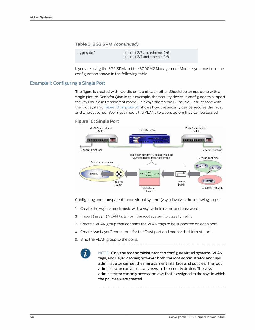
Table 5: 8G2 SPM (continued)
ethernet 2/5 and ethernet 2/6ethernet 2/7 and ethernet 2/8
aggregate 2
If you are using the 8G2 SPM and the 5000M2 Management Module, you must use the
configuration shown in the following table.
Example 1: Configuring a Single Port
The figure is created with two tifs on top of each other. Should be an eps done with a
single picture. Redo for Qian.In this example, the security device is configured to support
the vsys music in transparent mode. This vsys shares the L2-music-Untrust zone with
the root system. Figure 10 on page 50 shows how the security device secures the Trust
and Untrust zones. You must import the VLANs to a vsys before they can be tagged.
Figure 10: Single Port
Configuring one transparent mode virtual system (vsys) involves the following steps:
1. Create the vsys named music with a vsys admin name and password.
2. Import (assign) VLAN tags from the root system to classify traffic.
3. Create a VLAN group that contains the VLAN tags to be supported on each port.
4. Create two Layer 2 zones, one for the Trust port and one for the Untrust port.
5. Bind the VLAN group to the ports.
NOTE: Only the root administrator can configure virtual systems, VLANtags, and Layer 2 zones; however, both the root administrator and vsysadministrator can set themanagement interface and policies. The rootadministrator can access any vsys in the security device. The vsysadministrator canonlyaccess thevsys that isassigned to thevsys inwhichthe policies were created.
Copyright © 2012, Juniper Networks, Inc.50
Virtual Systems

6. Configure the policies for the vsys music. The policies configured in this example do
the following:
a. Permit HTTP traffic from the L2-music-Untrust zone to the L2-music-Trust zone
b. Deny all other traffic from the L2-music-Untrust zone to the L2-music-Trust zone
c. Permit all traffic from then L2-music-Trust zone to the L2-music-Untrust zone
7. Create the management interface. A VLAN management interface is created within
a vsys so that the vsys administrator can manage the vsys using a unique IP address
and VLAN ID
NOTE: ScreenOS 5.0-L2Vwith the security device can support up to 500virtual systems.
WebUI
1. Create VsysMusic
Vsys > Configure > New: Enter the following, then click OK:
Vsys Name: musicVsys Admin Name: vsys_musicVsys Admin New Password: xyzConfirm New Password: xyz
2. Import VLANs
Vsys > Configure > Click Enter (for vsys_music)
Network > Vlan > Import: Enter the following, then click Assign:
Import Vlan ID:Start: 100End: 199
3. Bind Ports
Network > Vlan > Group > Edit (for it_music) > Port: Enter the following, then click
Add:
port: (select) ethernet2/5zone: (select) L2-music-Trustport: (select) ethernet2/1zone: (select) L2-music-Untrust
4. Policies
Policies (From: L2-music-Untrust, To: L2-music-Trust) > New: Enter the following,
then click OK:
Source Address:Address Book Entry: (select) AnyDestination Address:Address Book Entry: (select) AnyService: (select) HTTP
51Copyright © 2012, Juniper Networks, Inc.
Chapter 3: VLAN-Based Traffic Classification

Action: (select) Permit
Policies (From: L2-music-Untrust, To: L2-music-Trust) > New: Enter the following,
then click OK:
Source Address:Address Book Entry: (select) AnyDestination Address:Address Book Entry: (select) AnyService: (select) ANYAction: (select) Deny
Policies (From: L2-music-Trust, To: L2-music-Untrust) > New: Enter the following,
then click OK:
Source Address:Address Book Entry: (select) AnyDestination Address:Address Book Entry: (select) AnyService: (select) ANYAction: (select) Permit
5. CreateManagement Interface
Network > Interfaces > (selectVLAN in the drop-down list) > New: Enter the following,
then click OK:
Interface Name Vlan: 199IP Address/Netmask: 1.0.1.199/24Management: (deselect)WebUI: (select)Telnet: (select)Ping: (select)
CLI
1. Create VsysMusic
device-> set vsysmusicdevice(music)-> set admin name vsys_musicdevice(music)-> set admin password xyzdevice(music)-> save
2. Import VLAN Tag
device(music)-> set vlan import 100 199
3. Create VLANGroups
device(music)-> set vlan group name it_musicdevice(music)-> set vlan group it_music 100 199
4. Create Layer 2 Zone
device(music)-> set zone name L2-music-Trust L2device(music)-> set zone name L2-music-Untrust L2
5. Bind Ports
device(music)-> set vlan port ethernet2/5 group it_music zone L2-music-Trustdevice(music)-> set vlan port ethernet2/1 group it_music zone L2-music-Untrust
Copyright © 2012, Juniper Networks, Inc.52
Virtual Systems
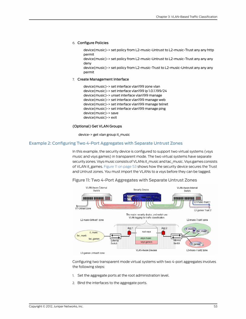
6. Configure Policies
device(music)-> set policy from L2-music-Untrust to L2-music-Trust any any httppermitdevice(music)-> set policy from L2-music-Untrust to L2-music-Trust any any anydenydevice(music)-> set policy from L2-music-Trust to L2-music-Untrust any any anypermit
7. CreateManagement Interface
device(music)-> set interface vlan199 zone vlandevice(music)-> set interface vlan199 ip 1.0.1.199/24device(music)-> unset interface vlan199managedevice(music)-> set interface vlan199manage webdevice(music)-> set interface vlan199manage telnetdevice(music)-> set interface vlan199manage pingdevice(music)-> savedevice(music)-> exit
(Optional) Get VLANGroups
device-> get vlan group it_music
Example 2: Configuring Two 4-Port Aggregates with Separate Untrust Zones
In this example, the security device is configured to support two virtual systems (vsys
music and vsys games) in transparent mode. The two virtual systems have separate
security zones. Vsys music consists of VLANs it_music and tac_music. Vsys games consists
of VLAN it_games. Figure 11 on page 53 shows how the security device secures the Trust
and Untrust zones. You must import the VLANs to a vsys before they can be tagged.
Figure 11: Two 4-Port Aggregates with Separate Untrust Zones
Configuring two transparent mode virtual systems with two 4-port aggregates involves
the following steps:
1. Set the aggregate ports at the root administration level.
2. Bind the interfaces to the aggregate ports.
53Copyright © 2012, Juniper Networks, Inc.
Chapter 3: VLAN-Based Traffic Classification

3. Create the vsys named music with a vsys admin name and password.
4. Import (assign) VLAN tags from the root system to classify traffic for the vsys music.
5. Create the VLAN groups that contain the vsys tags for each port supported in the vsys
music.
6. Create one Layer 2 zone for the Trust and Untrust interfaces in vsys music.
7. Bind aggregate ports to VLAN groups in the vsys music.
NOTE: Only the root administrator can configure virtual systems, VLANtags, and Layer 2 zones or bind aggregate ports; however, both the rootadministrator and vsys administrator can set policies andmanagementmodules.The rootadministrator canaccessanyvsys in thesecuritydevice.The vsys administrator can only access the vsys that is assigned to thevsys in which the policies were created.
8. Set the IP address for the L2-music-Trust zone in the vsys music.
9. Configure the policies for vsys music. The policies configured in this example do the
following:
a. Permit HTTP traffic from the L2-music-Untrust zone to 10.0.1.200
b. Deny all other traffic from the L2-music-Untrust zone to the L2-music-Trust zone
c. Permit all traffic from the L2-music-Trust zone to the L2-music-Untrust zone
10. Create the management interface. A VLAN management interface is created within
a vsys so that the vsys administrator can manage the vsys using a unique IP address
and VLAN ID.
11. Create the vsys named games with a vsys admin name and password.
12. Import (assign) VLAN tags from the root system to classify traffic for the vsys games.
13. Create the VLAN groups that contain the vsys tags for each port supported in the vsys
games.
14. Create one Layer 2 zone for the Trust and Untrust interfaces in the vsys games.
15. Bind aggregate ports to VLAN groups in the vsys games.
16. Configure the policies for the vsys games. The policies configured in this example do
the following:
a. Permit ftp traffic from the L2-games-Untrust zone to the L2-games-Trust zone
b. Deny all other traffic from the L2-games-Untrust zone to the L2-games-Trust zone
c. Permit all traffic from the L2-games-Trust zone to the L2-games-Untrust zone
17. Create the management interface.
Copyright © 2012, Juniper Networks, Inc.54
Virtual Systems

NOTE: ScreenOS supports up to 500 virtual systems.
NOTE: In this example, eachWebUI section lists only navigational paths,which lead to the pages necessary to configure the device. To see thespecific parameters and values you need to set for anyWebUI section,see the CLI section that follows it.
WebUI
1. Set Aggregate Ports in Root
Network > Interfaces > (select Aggregate IF in the right-hand drop-down list)> New
2. Bind Interfaces to Aggregate Ports
Network > Interfaces > Edit (for ethernet2/1)
Network > Interfaces > Edit (for ethernet2/2)
Network > Interfaces > Edit (for ethernet2/3)
Network > Interfaces > Edit (for ethernet2/4)
Network > Interfaces > Edit (for ethernet2/5)
Network > Interfaces > Edit (for ethernet2/6)
Network > Interfaces > Edit (for ethernet2/7)
Network > Interfaces > Edit (for ethernet2/8)
3. Create VsysMusic
Vsys > Configure > New
4. Import VLANs
Vsys > Configure > Click Enter (for vsys_music)
Network > Vlan > Import
5. Create Group
Network > Vlan > Group > New
6. Create Layer 2 Zones
Network > Zones > New
7. Bind Aggregate Ports
Network > Vlan > Group > Edit (for it_music) > Port
Network > Vlan > Group > Edit (for tac_music) > Port
8. Set IP Address
55Copyright © 2012, Juniper Networks, Inc.
Chapter 3: VLAN-Based Traffic Classification

Policy > Policy Elements > Addresses > List > V1-Untrust (select in the drop-down
list) > New
Policy > Policy Elements > Addresses > List > From: L2-music-Untrust To:
L2-music-Trust > New
Policy > Policy Elements > Addresses > List > From: L2-music-Untrust To:
L2-music-Trust > New
Policy > Policy Elements > Addresses > List > From: L2-music-Untrust To:
L2-music-Trust > New
Policy > Policy Elements > Addresses > List > From: L2-music-Trust To:
L2-music-Untrust > New
9. Policies
Policies (From: L2-music-Untrust, To: L2-music-Trust) > New
Policies (From: L2-music-Untrust, To: L2-music-Trust) > New
Policies (From: L2-music-Untrust, To: L2-music-Trust) > New
Policies (From: L2-music-Trust, To: L2-music-Untrust) > New
10. CreateManagement Interface
Network > Interfaces > (select VLAN in the right side drop-down list) > New
11. Create Vsys Games
Vsys > Configure > New
12. Import VLAN
Vsys > Configure > Click Enter (for vsys_games)
Network > Vlan > Import
13. Create Groups
Network > Vlan > Group > New
14. Create Layer 2 Zones
Network > Zones > New
15. Bind Aggregate Ports
Network > Vlan > Group > Edit (for games) > Port
16. Policies
Policies (From: L2-games-Untrust, To: L2-games-Trust) > New
Policies (From: L2-games-Untrust, To: L2-games-Trust) > New
Policies (From: L2-games-Trust, To: L2-games-Untrust) > New
17. CreateManagement Interface
Network > Interfaces > (select VLAN in the right side drop-down list) > New
Copyright © 2012, Juniper Networks, Inc.56
Virtual Systems

CLI
1. Set Aggregate Ports in Root
device-> set interface aggregate1 zone nulldevice-> set interface aggregate2 zone null
2. Bind Interfaces to Aggregate Ports
device-> set interface ethernet2/1 aggregate aggregate1device-> set interface ethernet2/2 aggregate aggregate1device-> set interface ethernet2/3 aggregate aggregate1device-> set interface ethernet2/4 aggregate aggregate1device-> set interface ethernet2/5 aggregate aggregate2device-> set interface ethernet2/6 aggregate aggregate2device-> set interface ethernet2/7 aggregate aggregate2device-> set interface ethernet2/8 aggregate aggregate2
3. Create VsysMusic
device-> set vsysmusicdevice(music)-> set admin name vsys_musicdevice(music)-> set admin password xyzdevice(music)-> save
4. Import VLAN Tag
device(music)-> set vlan import 100 199device(music)-> set vlan import 1033device(music)-> set vlan import 1133
5. Create VLANGroups
device(music)-> set vlan group name it_musicdevice(music)-> set vlan group it_music 100 199device(music)-> set vlan group name tac_musicdevice(music)-> set vlan group tac_music 1033device(music)-> set vlan group tac_music 1133
6. Create Layer 2 Zone
device(music)-> set zone name L2-music-Trust L2device(music)-> set zone name L2-music-Untrust L2
7. Bind Aggregate Ports
device(music)-> set vlan port aggregate2 group it_music zone L2-music-Trustdevice(music)-> set vlan port aggregate1 group it_music zone L2-music-Untrustdevice(music)-> set vlan port aggregate2 group tac_music zone L2-music-Trustdevice(music)-> set vlan port aggregate1 group tac_music zone L2-music-Untrust
8. Set IP Addresses
device(music)-> set address L2-music-Trust 10.0.1.200 10.0.1.200 255.255.255.0
9. Configure Policies
device(music)-> set policy from L2-music-Untrust to L2-music-Trust any 10.0.1.200http permitdevice(music)-> set policy from L2-music-Untrust to L2-music-Trust any any httppermitdevice(music)-> set policy from L2-music-Untrust to L2-music-Trust any any any
57Copyright © 2012, Juniper Networks, Inc.
Chapter 3: VLAN-Based Traffic Classification

denydevice(music)-> set policy from L2-music-Trust to L2-music-Untrust any any anypermit
10. CreateManagement Interface
device(music)-> set interface vlan1033 zone vlandevice(music)-> set interface vlan1033 ip 1.0.0.33/24device(music)-> set interface vlan199 zone vlandevice(music)-> set interface vlan199 ip 1.0.1.199/24device(music)-> unset interface vlan199managedevice(music)-> set interface vlan199manage pingdevice(music)-> set interface vlan199manage httpsdevice(music)-> set interface vlan199manage telnetdevice(music)-> savedevice(music)-> exit
(Optional) Get VLANGroups
device-> get vlan group it_musicdevice-> get vlan group tac_music
11. Create Vsys Games
device-> set vsys gamesdevice(games)-> set admin name vsys_gamesdevice(games)-> set admin password abcdevice(games)-> save
12. Import VLAN Tag
device(games)-> set vlan import 200 250
13. Create VLANGroups
device(games)-> set vlan group name gamesdevice(games)-> set vlan group games 200 250
14. Create Layer 2 Zone
device(games)-> set zone name L2-games-Trust L2device(games)-> set zone name L2-games-Untrust L2
15. Bind Aggregate Ports
device(games)-> set vlan port aggregate2 group games zone L2-games-trustdevice(games)-> set vlan port aggregate1 group games zone L2-games-Untrust
16. Configure Policies
device(games)-> set policy from L2-games-Untrust to L2-games-Trust any any ftppermitdevice(games)-> set policy from L2-games-Untrust to L2-games-Trust any any anydenydevice(games)-> set policy from L2-games-Trust to L2-games-Untrust any any anypermit
17. CreateManagement Interface
device(games)-> set interface vlan300 zone vlandevice(games)-> set interface vlan300 ip 1.0.0.20/24device(games)-> unset interface vlan300managedevice(games)-> set interface vlan300manage web
Copyright © 2012, Juniper Networks, Inc.58
Virtual Systems
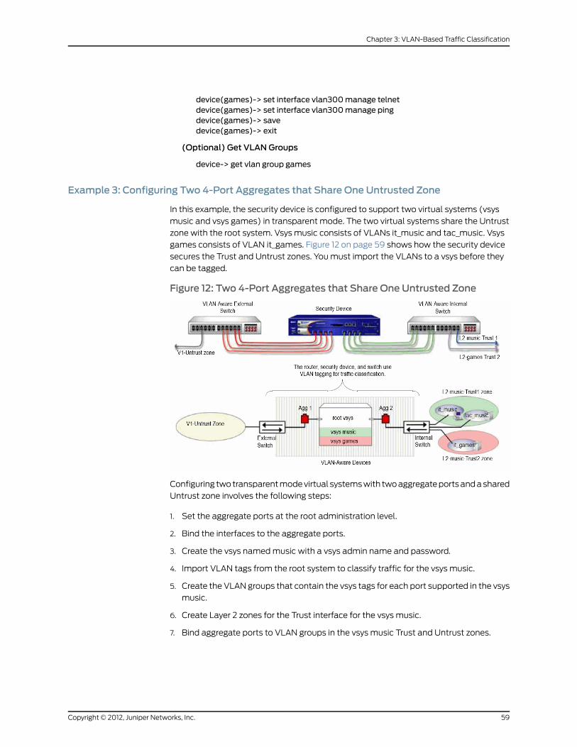
device(games)-> set interface vlan300manage telnetdevice(games)-> set interface vlan300manage pingdevice(games)-> savedevice(games)-> exit
(Optional) Get VLANGroups
device-> get vlan group games
Example 3: Configuring Two 4-Port Aggregates that Share One Untrusted Zone
In this example, the security device is configured to support two virtual systems (vsys
music and vsys games) in transparent mode. The two virtual systems share the Untrust
zone with the root system. Vsys music consists of VLANs it_music and tac_music. Vsys
games consists of VLAN it_games. Figure 12 on page 59 shows how the security device
secures the Trust and Untrust zones. You must import the VLANs to a vsys before they
can be tagged.
Figure 12: Two 4-Port Aggregates that Share One Untrusted Zone
Configuring two transparent mode virtual systems with two aggregate ports and a shared
Untrust zone involves the following steps:
1. Set the aggregate ports at the root administration level.
2. Bind the interfaces to the aggregate ports.
3. Create the vsys named music with a vsys admin name and password.
4. Import VLAN tags from the root system to classify traffic for the vsys music.
5. Create the VLAN groups that contain the vsys tags for each port supported in the vsys
music.
6. Create Layer 2 zones for the Trust interface for the vsys music.
7. Bind aggregate ports to VLAN groups in the vsys music Trust and Untrust zones.
59Copyright © 2012, Juniper Networks, Inc.
Chapter 3: VLAN-Based Traffic Classification
NOTE: Only the root administrator can configure virtual systems, VLANtags, and Layer 2 zones or bind aggregate ports; however, both the rootadministrator and vsys administrator can set policies andmanagementmodules.The rootadministrator canaccessanyvsys in thesecuritydevice.The vsys administrator can only access the vsys that is assigned to thevsys in which the policies were created.
8. Set the IP address for each zone in the vsys music.
9. Configure the policies for the vsys music. The policies configured in this example do
the following:
a. Permit all traffic from 10.0.1.200 to 10.0.1.100
b. Permit all traffic from 10.0.1.201 to 10.0.1.101
c. Deny all traffic from the V1-Untrust zone to the L2-music-Trust zone
10. Create the management interface. A VLAN management interface is created within
a vsys so that the vsys administrator can manage the vsys using a unique IP address
and VLAN ID.
11. Create the vsys named games with a vsys admin name and password.
12. Import VLAN tags from the root system to classify traffic for the vsys games.
13. Create the VLAN groups that contain the vsys tags for each port supported in the vsys
games.
14. Create Layer 2 zones for the Trust interface for the vsys games.
15. Bind aggregate ports to VLAN groups in the vsys games.
16. Set the IP address for each zone in the vsys games.
17. Configure the policies for the vsys games. The policies configured in this example do
the following:
a. Permit all traffic from 20.0.1.200 to 20.0.1.100
b. Permit all traffic from 20.0.1.201 to 20.0.1.101
c. Deny all traffic from the V1-Untrust zone to the L2-games-Trust1 zone
18. Create the management interface.
NOTE: ScreenOS 5 supports up to 500 virtual systems.
NOTE: In this example, eachWebUI section lists only navigational paths,which lead to the pages necessary to configure the device. To see thespecific parameters and values you need to set for anyWebUI section,see the CLI section that follows it.
Copyright © 2012, Juniper Networks, Inc.60
Virtual Systems

WebUI
1. Set Aggregate Ports in Root
Network > Interfaces > (select Aggregate IF in the drop-down list four times)
2. Bind Interfaces to Aggregate Ports
Network > Interfaces > Edit (for ethernet2/1 to aggregate1)
Network > Interfaces > Edit (for ethernet2/2 to aggregate1)
Network > Interfaces > Edit (for ethernet2/3 to aggregate1)
Network > Interfaces > Edit (for ethernet2/4 to aggregate1)
Network > Interfaces > Edit (for ethernet2/5 to aggregate2)
Network > Interfaces > Edit (for ethernet2/6 to aggregate2)
Network > Interfaces > Edit (for ethernet2/7 to aggregate2)
Network > Interfaces > Edit (for ethernet2/8 to aggregate2)
3. Create VsysMusic
Vsys > Configure > New
4. Import VLANs
Vsys > Configure > Click Enter (for vsys_music)
Network > Vlan > Import
5. Create Group
Network > Vlan > Group > New: 100-199
Network > Vlan > Group > New: 1033-1033
Network > Vlan > Group > New: 1133-1133
6. Create Layer 2 Zones
Network > Zones > New: L2-music-Trust1
Network > Zones > New: L2-music-Trust2
7. Bind Aggregate Ports
Network > Vlan > Group > Edit (for music) > Port
8. Set IP Address
Policy > Policy Elements > Addresses > List > (select V1-Untrust in the drop-down
list) > New
Policy > Policy Elements > Addresses > List > (select L2-music-Trust1 in the drop-down
list)
Policy > Policy Elements > Addresses > List > (select L2-music-Trust2 in the
drop-down list
9. Policies
61Copyright © 2012, Juniper Networks, Inc.
Chapter 3: VLAN-Based Traffic Classification

Policies (From: L2-music-Trust1, To: V1-Untrust) > New
Policies (From: L2-music-Trust2, To: V1-Untrust) > New
Policies (From: V1-Untrust, To: L2-music-Trust2) > New
Policies (From: V1-Untrust, To: L2-music-Trust1) > New
10. CreateManagement Interface
Network > Interfaces > (select VLAN in the right side drop-down list) > New
Network > Interfaces > (select VLAN in the right side drop-down list) > New
11. Create Vsys Games
Vsys > Configure > New
12. Import VLANs
Vsys > Configure > Click Enter (for vsys_games)
Network > Vlan > Import
13. Create Group
Network > Vlan > Group > New: 200-299
Network > Vlan > Group > New: 50-50
14. Create Layer 2 Zones
Network > Zones > New: L2-games-Trust1
Network > Zones > New: L2-games-Trust2
15. Bind Aggregate Ports
Network > Vlan > Group > Edit (for games) > Port
16. Set IP Addresses
Policy > Policy Elements > Addresses > List > (select V1-Untrust in the right-hand
drop-down list) > New
17. Policies
Policies (From: L2-games-Trust1, To: V1-Untrust) > New
18. CreateManagement Interface
Network > Interfaces > (select VLAN in the drop-down list) > New
CLI
1. Set Aggregate Ports in Root
device-> set interface aggregate1 zone nulldevice-> set interface aggregate2 zone null
2. Bind Interfaces to Aggregate Ports
device-> set interface ethernet2/1 aggregate aggregate1device-> set interface ethernet2/2 aggregate aggregate1
Copyright © 2012, Juniper Networks, Inc.62
Virtual Systems

device-> set interface ethernet2/3 aggregate aggregate1device-> set interface ethernet2/4 aggregate aggregate1device-> set interface ethernet2/5 aggregate aggregate2device-> set interface ethernet2/6 aggregate aggregate2device-> set interface ethernet2/7 aggregate aggregate2device-> set interface ethernet2/8 aggregate aggregate2
3. Create VsysMusic
device-> set vsysmusicdevice(music)-> set admin name vsys_musicdevice(music)-> set admin password xyzdevice(music)-> save
4. Import VLAN Tag
device(music)-> set vlan import 100 199device(music)-> set vlan import 1033
5. Create VLANGroups
device(music)-> set vlan group namemusicdevice(music)-> set vlan groupmusic 100 199device(music)-> set vlan groupmusic 1033
6. Create Layer 2 Zone
device(music)-> set zone name L2-music-Trust1 L2device(music)-> set zone name L2-music-Trust2 L2
7. Bind Aggregate Ports
device(music)-> set vlan port aggregate2 groupmusic zone L2-music-Trust1device(music)-> set vlan port aggregate2 groupmusic zone L2-music-Trust2device(music)-> set vlan port aggregate1 groupmusic zone V1-Untrust
8. Set IP Address
device(music)-> set address V1-Untrust 10.0.1.100 10.0.1.100 255.255.255.255device(music)-> set address V1-Untrust 10.0.1.101 10.0.1.101 255.255.255.255device(music)-> set address L2-music-Trust1 10.0.1.200 10.0.1.200 255.255.255.255device(music)-> set address L2-music-Trust2 10.0.1.201 10.0.1.201 255.255.255.255
9. Configure Policies
device(music)->setpolicy id 1 fromL2-music-Trust1 toV1-Untrust 10.0.1.20010.0.1.100any permitdevice(music)->setpolicy id2 fromL2-music-Trust2 toV1-Untrust 10.0.1.201 10.0.1.101any permitdevice(music)-> set policy id 3 fromV1-Untrust to L2-music-Trust2 any any any denydevice(music)-> set policy id 4 fromV1-Untrust to L2-music-Trust1 any any any deny
10. CreateManagement Interface
device(music)-> set interface vlan1033 zone vlandevice(music)-> set interface vlan1033 ip 1.0.0.33/24device(music)-> set interface vlan199 zone vlandevice(music)-> set interface vlan199 ip 1.0.1.199/24device(music)-> unset interface vlan199managedevice(music)-> set interface vlan199manage webdevice(music)-> set interface vlan199manage telnetdevice(music)-> set interface vlan199manage ping
63Copyright © 2012, Juniper Networks, Inc.
Chapter 3: VLAN-Based Traffic Classification
device(music)-> savedevice(music)-> exit
(Optional) Get VLANGroups
device-> get vlan groupmusic
11. Create Vsys Games
device-> set vsys gamesdevice(games)-> set admin name vsys_gamesdevice(games)-> set admin password abcdevice(games)-> save
12. Import VLAN Tag
device(games)-> set vlan import 200 299device(games)-> set vlan import 50
13. Create VLANGroups
device(games)-> set vlan group name gamesdevice(games)-> set vlan group games 200 299device(games)-> set vlan group games 50
14. Create Layer 2 Zone
device(games)-> set zone name L2-games-Trust1 L2device(games)-> set zone name L2-games-Trust2 L2
15. Bind Aggregate Ports
device(games)-> set vlan port aggregate2 group games zone L2-games-Trust1device(games)-> set vlan port aggregate2 group games zone L2-games-Trust2device(games)-> set vlan port aggregate1 group games zone V1-Untrust
16. Set IP Address
device(games)-> set address V1-Untrust 20.0.1.100 20.0.1.100 255.255.255.255device(games)-> set address V1-Untrust 20.0.1.101 20.0.1.101 255.255.255.255device(games)->setaddressL2-games-Trust120.0.1.20020.0.1.200255.255.255.255device(games)->setaddressL2-games-Trust220.0.1.20120.0.1.201255.255.255.255
17. Configure Policies
device(games)-> set policy id 1 from L2-games-Trust1 to V1-Untrust 20.0.1.20020.0.1.100 any permitdevice(games)-> set policy id 2 from L2-games-Trust1 to V1-Untrust 20.0.1.20120.0.1.101 any permitdevice(games)->setpolicy id3 fromV1-Untrust toL2-games-Trust1anyanyanydeny
18. CreateManagement Interface
device(games)-> set interface vlan300 zone vlandevice(games)-> set interface vlan300 ip 1.0.0.20/24device(games)-> unset interface vlan300managedevice(games)-> set interface vlan300manage webdevice(games)-> set interface vlan300manage telnetdevice(games)-> set interface vlan300manage pingdevice(games)-> savedevice(games)-> exit
(Optional) Get VLANGroups
Copyright © 2012, Juniper Networks, Inc.64
Virtual Systems

device-> get vlan group games
Defining Subinterfaces and VLAN Tags
The Trust-vsys_name zone subinterface links a vsys to its internal VLAN. The Untrust
zone subinterface links a vsys to the public WAN, usually the Internet. A subinterface has
the following attributes:
• A unique VLAN ID (from 1 to 4095)
• A public or private IP address (the IP address is private by default)
• A netmask for a class A, B, or C subnet
• An associated VLAN
NOTE: For information about public and private IP addresses, see PublicIP Addresses and Private IP Addresses.
A vsys can have a single Untrust zone subinterface and multiple Trust-vsys_name zone
subinterfaces. If a virtual system does not have its own Untrust zone subinterface, it
shares the root level Untrust zone interface. Security devices also support subinterfaces,
VLANs at the root level, and IEEE 802.1Q-compliant VLAN tags.
Figure 13: VLAN Subinterfaces
A VLAN tag is an added bit in the Ethernet frame header that indicates membership in a
particular VLAN. By binding a VLAN to a vsys, the tag also determines to which vsys a
frame belongs, and consequently, which policy is applied to that frame. If a VLAN is not
bound to a vsys, policies set in the root system of the security device are applied to the
frame.
A root-level administrator can create a VLAN, assign members to it, and bind it to a vsys.
(The assigning of members to a VLAN can be done by several methods—protocol type,
MAC address, port number—and is beyond the scope of this document.) The vsys admin,
if there is one, then manages the vsys through the creation of addresses, users, services,
VPNs, and policies. If there is no vsys admin, then a root-level administrator performs
these tasks.
65Copyright © 2012, Juniper Networks, Inc.
Chapter 3: VLAN-Based Traffic Classification

NOTE: If the root-level admin does not associate aVLAN to a vsys, theVLANoperates within the root system of the security device.All subnets in a vsysmust be disjointed; that is, theremust be nooverlappingIPaddressesamongthesubnets in thesamevsys. Forexample:Subinterface1– 10.2.2.1 255.255.255.0 and Subinterface2 – 10.2.3.1 255.255.255.0 aredisjointed and link to acceptable subnets.However, subnets with the following subinterfaces overlap and areunacceptable within the same vsys: subinterface1 – 10.2.2.1 255.255.0.0 andsubinterface2 – 10.2.3.1 255.255.0.0.The address ranges of subnets in different vsys can overlap.
In this example, you define subinterfaces and VLAN tags for the three virtual systems
that you created in “Creating a Virtual System Object and Admin” on page 5—vsys1,
vsys2, and vsys3. The first two subinterfaces are for two private virtual systems operating
in NAT mode, and the third subinterface is for a public virtual system operating in route
mode. The subinterfaces are 10.1.1.1/24, 10.2.2.1/24, and 1.3.3.1/24. You create all three
subinterfaces on ethernet3/2.
All three virtual systems share the Untrust zone and its interface (ethernet1/1; 1.1.1.1/24)
with the root system. The Untrust zone is in the untrust-vr routing domain.
WebUI
1. Vsys1 Subinterface and VLAN Tag
Vsys > Configure > Click Enter (for vsys1).
Network > Interfaces > New Sub-IF (for ethernet3/2): Enter the following, then click
OK:
Interface Name: ethernet3/2.1Zone Name: Trust-vsys1IP Address / Netmask: 10.1.1.1/24VLAN Tag: 1
NOTE: You can define virtual systems to operate in routemode or NATmode.Thedefault isNATmode,and it isunnecessary tospecifyNATwhencreating the first two subinterfaces in this example.
2. Vsys2 Subinterface and VLAN Tag
Vsys > Configure > Click Enter (for vsys2).
Network > Interfaces > New Sub-IF (for ethernet3/2): Enter the following, then click
OK:
Interface Name: ethernet3/2.2Zone Name: Trust-vsys2IP Address / Netmask: 10.2.2.1/24VLAN Tag: 2
3. Vsys3 Subinterface and VLAN Tag
Copyright © 2012, Juniper Networks, Inc.66
Virtual Systems

Vsys > Configure > Click Enter (for vsys3).
Network > Interfaces > New Sub-IF (for ethernet3/2): Enter the following, then click
Apply:
Interface Name: ethernet3/2.3Zone Name: Trust-vsys3IP Address / Netmask: 1.3.3.1/24VLAN Tag: 3
Select InterfaceMode: Route, then click OK.
Click Exit Vsys to return to the root level.
CLI
1. Vsys1 Subinterface and VLAN Tag
device-> enter vsys vsys1device(vsys1)-> set interface ethernet3/2.1 zone trust-vsys1device(vsys1)-> set interface ethernet3/2.1 ip 10.1.1.1/24 tag 1device(vsys1)-> savedevice(vsys1)-> exit
NOTE: You can define virtual systems to operate in routemode or NATmode.Thedefault isNATmode,and it isunnecessary tospecifyNATwhencreating the first two subinterfaces in this example.
2. Vsys2 Subinterface and VLAN Tag
device-> enter vsys vsys2device(vsys2)-> set interface ethernet3/2.2 zone trust-vsys2device(vsys2)-> set interface ethernet3/2.2 ip 10.2.2.1/24 tag 2device(vsys2)-> savedevice(vsys2)-> exit
3. Vsys3 Subinterface and VLAN Tag
device-> enter vsys vsys3device(vsys3)-> set interface ethernet3/2.3 zone trust-vsys3device(vsys3)-> set interface ethernet3/2.3 ip 1.3.3.1/24 tag 3device(vsys3)-> set interface ethernet3/2.3 routedevice(vsys3)-> savedevice(vsys3)-> exit
Communicating Between Virtual Systems
The members of a VLAN within a vsys have unrestricted communication access with
each other. The VLAN members of different virtual systems cannot communicate with
one another unless the participating vsys administrators specifically configure policies
allowing the members of their respective systems to do so.
Traffic between root-level VLANs operates within the parameters set by root-level
policies. Traffic between virtual system VLANs operates within the parameters set by
67Copyright © 2012, Juniper Networks, Inc.
Chapter 3: VLAN-Based Traffic Classification

the participating virtual system policies. The security device passes only traffic allowed
to leave the originating virtual system and allowed to enter the destination virtual system.
In other words, the vsys admins of both virtual systems must set policies allowing the
traffic to flow in the appropriate direction—outgoing and incoming.
NOTE: Policies set in the root system and in virtual systems do not affecteach other.
In this example configuration shown in Figure 14 on page 68, the admins for vsys1 and
vsys2—see “Defining Subinterfaces and VLAN Tags” on page 65—set up policies to enable
traffic between a workstation (work_js with the IP address 10.1.1.10/32) in VLAN1 and a
server (ftp_server with the IP address 10.2.2.20/32) in VLAN2. The connection is possible
if the following two conditions are met:
• The vsys admin for vsys1 has set a policy permitting traffic from the workstation in
Trust-vsys1 to the server in its Untrust zone.
• The vsys admin for vsys2 has set a policy permitting traffic from the workstation in its
Untrust zone to the server in Trust-vsys2.
The network device in front of the internal interface on the security device is a Layer 2
switch. This forces traffic from VLAN1 going to VLAN2 to go through the switch to the
security device for Layer 3 routing. If the network device were a Layer 3 router, traffic
between VLAN1 and VLAN2 could pass through the router, bypassing all policies set on
the security device.
The vsys1 and vsys2 admins also set up the appropriate routes. The shared Untrust zone
is in the untrust-vr and the Trust zones in vsys1 and vsys2.
Figure 14: InterVsys Communication
WebUI
1. Vsys1
Addresses
Policy > Policy Elements > Addresses > List > New: Enter the following, then clickOK:
Address Name: work_jsIP Address/Domain Name:IP/Netmask: (select), 10.1.1.10/32
Zone: Trust-vsys1
Copyright © 2012, Juniper Networks, Inc.68
Virtual Systems

Policy > Policy Elements > Addresses > List > New: Enter the following, then clickOK:
Address Name: ftp_serverIP Address/Domain Name:IP/Netmask: (select), 10.2.2.20/32
Zone: Untrust
Routes
Network > Routing > Routing Entries > untrust-vr New: Enter the following, then click
OK:
Network Address/Netmask: 10.1.1.0/24Next Hop Virtual Router Name: (select); vsys1-vr
Policy
Network > Routing > Routing Entries > vsys1-vr New: Enter the following, then click
OK:
Network Address/Netmask: 0.0.0.0/0Gateway: (select)Next Hop Virtual Router Name: (select); untrust-vr
Policies > (From: Trust-vsys1, To: Untrust) New: Enter the following, then click OK:
Source Address:Address Book Entry: (select), work_js
Destination Address:Address Book Entry: (select), ftp_server
Service: FTP-GetAction: Permit
2. Vsys2
Addresses
Policy > Policy Elements > Addresses > List > New: Enter the following, then clickOK:
Address Name: ftp_serverIP Address/Domain Name:IP/Netmask: (select), 10.2.2.2/32
Zone: Trust-vsys2
Policy > Policy Elements > Addresses > List > New: Enter the following, then clickOK:
Address Name: work_jsIP Address/Domain Name:IP/Netmask: (select), 10.1.1.10/32
Zone: Untrust
Routes
Network > Routing > Routing Entries > untrust-vr New: Enter the following, then click
OK:
Network Address/Netmask: 10.2.2.0/24Next Hop Virtual Router Name: (select); vsys2-vr
Network > Routing > Routing Entries > vsys2-vr New: Enter the following, then click
OK:
69Copyright © 2012, Juniper Networks, Inc.
Chapter 3: VLAN-Based Traffic Classification

Network Address/Netmask: 0.0.0.0/0Next Hop Virtual Router Name: (select); untrust-vr
Policy
Policies > (From: Untrust, To: Trust-vsys2) New: Enter the following, then click OK:
Source Address:Address Book Entry: (select), work_js
Destination Address:Address Book Entry: (select), ftp_server
Service: FTP-GetAction: Permit
CLI
1. Vsys1
Addresses
set address trust-vsys1 work_js 10.1.1.10/32set address untrust ftp_server 10.2.2.20/32
Routes
set vrouter untrust-vr route 10.1.1.0/24 vrouter vsys1-vrset vrouter vsys1-vr route 0.0.0.0/0 vrouter untrust-vr
Policy
set policy from trust-vsys1 to untrust work_js ftp_server ftp-get permitsave
2. Vsys2
Addresses
set address trust-vsys2 ftp_server 10.2.2.20/32set address untrust work_js 10.1.1.10/32
Routes
set vrouter untrust-vr route 10.2.2.0/24 vrouter vsys2-vrset vrouter vsys2-vr route 0.0.0.0/0 vrouter untrust-vr
Policy
set policy from untrust to trust-vsys2 work_js ftp_server ftp-get permitsave
Network > Zones > Edit (for Internal): Select the IP Classification check box, then click
OK.
VLANRetagging
VLAN retagging provides a way to selectively screen VLAN traffic. You place a security
device in parallel with your Layer 2 switch (see Figure 15 on page 71) and configure the
switch to direct to the security device only traffic from VLANs you want screened. Traffic
to and from your other VLANs continues to pass directly through the switch, thus avoiding
Copyright © 2012, Juniper Networks, Inc.70
Virtual Systems

any impact to throughput that might be caused by passing all VLAN traffic through the
security device.
NOTE: The current release of ScreenOS supports VLAN retagging on ISGplatforms.
VLAN retagging requires that retagged traffic be from VLANs with different IDs, that is,
you cannot retag VLAN traffic from VLAN 10 to another VLAN with the same ID.
You configure VLAN retagging on the security device by creating a bidirectional VLAN
retagging object and specifying the two VLANs for which you want it to screen traffic.
(You must also bind it to an interface and create a policy.) For example, the following
command creates a VLAN retagging object called secure_vlan that retags traffic from
VLAN 10 to 20 and from VLAN 20 to 10:
set vlan retag name secure_vlan 10 20
The security device stores this retagging pair in a hash table and references it when it
receives traffic from either of those VLANs. You must also assign the appropriate VLAN
tags to the ports on your Layer 2 switch that connect to the security device.
Figure 15 on page 71 illustrates this scenario.
Figure 15: VLAN Retagging Operation
Configuring VLAN Retagging
To configure a VLAN retagging pair from the WebUI,
Network > VLAN > Retagging
71Copyright © 2012, Juniper Networks, Inc.
Chapter 3: VLAN-Based Traffic Classification
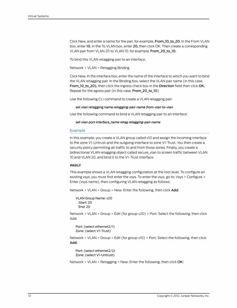
Click New, and enter a name for the pair, for example, From_10_to_20. In the From VLAN
box, enter 10. In the To VLAN box, enter 20, then click OK. Then create a corresponding
VLAN pair from VLAN 20 to VLAN 10, for example, From_20_to_10.
To bind this VLAN retagging pair to an interface,
Network > VLAN > Retagging Binding
Click New. In the Interface box, enter the name of the interface to which you want to bind
the VLAN retagging pair. In the Binding box, select the VLAN pair name (in this case,
From_10_to_20), then click the Ingress check box in the Direction field then click OK.Repeat for the egress pair (in this case, From_20_to_10)
Use the following CLI command to create a VLAN retagging pair:
set vlan retagging name retagging-pair-name from-vlan to-vlan
Use the following command to bind a VLAN retagging pair to an interface:
set vlan port interface_name retag retagging-pair-name
Example
In this example, you create a VLAN group called v10 and assign the incoming interface
to the zone V1-Untrust and the outgoing interface to zone V1-Trust. You then create a
security policy permitting all traffic to and from those zones. Finally, you create a
bidirectional VLAN retagging object called secure_vlan to screen traffic between VLAN
10 and VLAN 20, and bind it to the V1-Trust interface.
WebUI
This example shows a VLAN retagging configuration at the root level. To configure an
existing vsys, you must first enter the vsys. To enter the vsys, go to: Vsys > Configure >
Enter (vsys name), then configuring VLAN retagging as follows:
Network > VLAN > Group > New: Enter the following, then click Add:
VLAN Group Name: v20Start: 20End: 20
Network > VLAN > Group > Edit (for group v20) > Port: Select the following, then click
Add:
Port: (select ethernet2/1)Zone: (select V1-Trust)
Network > VLAN > Group > Edit (for group v10) > Port: Select the following, then click
Add:
Port: (select ethernet2/2)Zone: (select V1-Untrust)
Network > VLAN > Retagging > New: Enter the following, then click OK:
Copyright © 2012, Juniper Networks, Inc.72
Virtual Systems
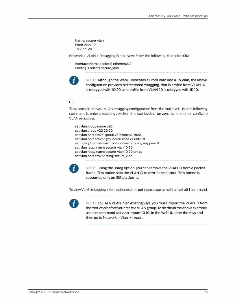
Name: secure_vlanFrom Vlan: 10To Vlan: 20
Network > VLAN > Retagging Bind> New: Enter the following, then click OK:
Interface Name: (select) ethernet2/2Binding: (select) secure_vlan
NOTE: Although theWebUI indicates a FromVlan and a To Vlan, the aboveconfiguration provides bidirectional retagging, that is, traffic from VLAN 10is retagged with ID 20, and traffic from VLAN 20 is retagged with ID 10.
CLI
This example shows a VLAN retagging configuration from the root level. Use the following
command to enter an existing vsys from the root level:entervsys name_str, then configure
VLAN retagging:
set vlan group name v20set vlan group v20 20 20set vlan port eth2/1 group v20 zone v1-trustset vlan port eth2/2 group v20 zone v1-untrustset policy from v1-trust to v1-untrust any any any permitset vlan retag name secure_vlan 10 20set vlan retag name secure_vlan 10 20 untagset vlan port eth2/2 retag secure_vlan
NOTE: Using the untag option, you can remove the VLAN ID from a packetframe. This option sets the VLAN ID to zero in the output. This option issupported only on ISG platforms.
To view VLAN retagging information, use thegetvlan retagname[name|all ]command.
NOTE: To use a VLAN in an existing vsys, youmust import the VLAN ID fromthe rootvsysbeforeyoucreateaVLANgroup.Todothis in theaboveexample,use the command set vlan import 10 10. In theWebUI, enter the vsys andthen go to Network > Vlan > Import.
73Copyright © 2012, Juniper Networks, Inc.
Chapter 3: VLAN-Based Traffic Classification

Copyright © 2012, Juniper Networks, Inc.74
Virtual Systems
CHAPTER 4
IP-Based Traffic Classification
This chapter explains IP-based traffic classification for virtual systems. It contains the
following sections:
• Overview on page 75
• Managing Inter-Vsys Traffic with a Shared DMZ Zone on page 76
• Designating an IP Range to the Root System on page 77
• Configuring IP-Based Traffic Classification on page 77
Overview
Figure 16 on page 76 shows how IP-based traffic classification allows you to use virtual
systems without VLANs. Instead of VLAN tags, the security device uses IP addresses to
sort traffic, associating a subnet or range of IP addresses with a particular system—root
or vsys. Using IP-based traffic classification exclusively to sort traffic, all systems share
the following:
• The untrust-vr and a user-defined internal-vr
• The Untrust zone and a user-defined internal zone
• An Untrust zone interface and a user-defined internal zone interface
NOTE: Even when using VLAN-based traffic classification for internaltraffic, for external traffic all systems use the shared Untrust zone—and,unlessasystemhasa dedicated interface, a sharedUntrust zone interface.Using a shared interface on one side and a dedicated interface (with VLANtagging) on the other constitutes a hybrid approach. VLAN-based andIP-based traffic classificationcancoexistwithin thesamesystemoramongdifferent systems simultaneously.
75Copyright © 2012, Juniper Networks, Inc.

Figure 16: IP-Based Traffic Classification
Managing Inter-Vsys Traffic with a Shared DMZ Zone
Virtual systems across different zones generally use a shared Untrust zone for
communication. However, inter-vsys traffic through a shared Untrust zone is often
interrupted by external traffic and overlapping IP addresses. To overcome such traffic
interference in the shared Untrust zone, you can use a shared DMZ zone created at the
root level. Each shared DMZ zone that the root admin creates is automatically assigned
to a nonsharable virtual router (VR). The root admin also determines to which shared
DMZ zone a particular vsys should be subscribed. A shared DMZ zone is shared only with
the virtual systems that are subscribed to it. However, each vsys can be subscribed to
only one shared DMZ zone.
WebUI
Network > Zones >New: Enter the following, then click OK:
Zone name: smdzVirtual Router Name: sdmz_vrZone Type: Shared-DMZ-Zone (select)
CLI
1. Creating a Shared-DMZ Zone
set zone name zone shared-dmzsave
2. Subscribing a Vsys to a Shared-DMZ Zone
set vsys name_str shared-dmz zonesave
Copyright © 2012, Juniper Networks, Inc.76
Virtual Systems

NOTE: A shared DMZ zone works only on a security device running inNAT/routemode and cannot be bound to any interface other than theloopback interface. However, the default interface for the shared DMZzone is Null.
Designating an IP Range to the Root System
To designate a subnet or range of IP addresses to the root system or to a previously
created virtual system, you must do either of the following at the root level:
WebUI
Network > Zones > Edit (for zone) > IP Classification: Enter the following, then click OK:
System: (select root or vsys_name_str)AddressType: (selectSubnetandenter ip_addr/mask, or selectRangeandenter ip_addr1– ip_addr2)
CLI
set zone zone ip-classification net ip_addr/mask { root | vsys name_str }set zone zone ip-classification range ip_addr1-ip_addr2 { root | vsys name_str }
Because IP-based traffic classification requires the use of a shared security zone, virtual
systems cannot use overlapping internal IP addresses, as is possible with VLAN-based
traffic classification. Also, because all the systems share the same internal interface, the
operational mode for that interface must be either NAT or route mode; you cannot mix
NAT and route modes for different systems. In this regard, the addressing scheme of an
IP-based approach is not as flexible as that allowed by the more commonly used
VLAN-based approach.
Sharing virtual routers, security zones, and interfaces is inherently less secure than
dedicating an internal virtual router, internal security zone, and internal and external
interfaces to each vsys. When all virtual systems share the same interfaces, it is possible
for a vsys admin in one vsys to use the snoop command to gather information about the
traffic activities of another vsys. Also, because IP-spoofing is possible on the internal
side, we recommend that you disable the IP-spoofing SCREEN option on the shared
internal interface. When deciding which traffic classification scheme to use, you must
weigh the ease of management offered by the IP-based approach against the increased
security and greater addressing flexibility offered by the VLAN-based approach.
Configuring IP-Based Traffic Classification
In this example, you set up IP-based traffic classification for the three virtual systems
created in “Creating a Virtual System Object and Admin” on page 5. You define the
trust-vr as sharable. You create a new zone, name it Internal, and bind it to the trust-vr.
You then make the Internal zone sharable. You bind ethernet3/2 to the shared Internal
zone, assign it IP address 10.1.0.1/16, and select NAT mode.
77Copyright © 2012, Juniper Networks, Inc.
Chapter 4: IP-Based Traffic Classification
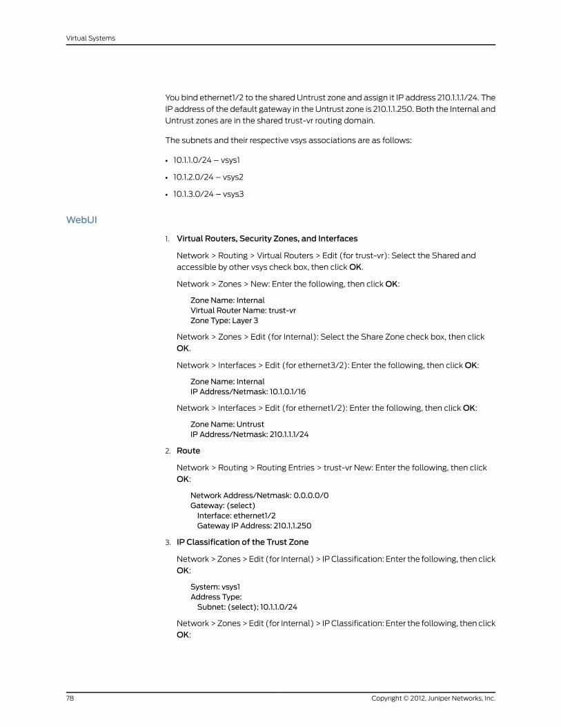
You bind ethernet1/2 to the shared Untrust zone and assign it IP address 210.1.1.1/24. The
IP address of the default gateway in the Untrust zone is 210.1.1.250. Both the Internal and
Untrust zones are in the shared trust-vr routing domain.
The subnets and their respective vsys associations are as follows:
• 10.1.1.0/24 – vsys1
• 10.1.2.0/24 – vsys2
• 10.1.3.0/24 – vsys3
WebUI
1. Virtual Routers, Security Zones, and Interfaces
Network > Routing > Virtual Routers > Edit (for trust-vr): Select the Shared and
accessible by other vsys check box, then click OK.
Network > Zones > New: Enter the following, then click OK:
Zone Name: InternalVirtual Router Name: trust-vrZone Type: Layer 3
Network > Zones > Edit (for Internal): Select the Share Zone check box, then click
OK.
Network > Interfaces > Edit (for ethernet3/2): Enter the following, then click OK:
Zone Name: InternalIP Address/Netmask: 10.1.0.1/16
Network > Interfaces > Edit (for ethernet1/2): Enter the following, then click OK:
Zone Name: UntrustIP Address/Netmask: 210.1.1.1/24
2. Route
Network > Routing > Routing Entries > trust-vr New: Enter the following, then click
OK:
Network Address/Netmask: 0.0.0.0/0Gateway: (select)Interface: ethernet1/2Gateway IP Address: 210.1.1.250
3. IP Classification of the Trust Zone
Network > Zones > Edit (for Internal) > IP Classification: Enter the following, then click
OK:
System: vsys1Address Type:Subnet: (select); 10.1.1.0/24
Network > Zones > Edit (for Internal) > IP Classification: Enter the following, then click
OK:
Copyright © 2012, Juniper Networks, Inc.78
Virtual Systems

System: vsys2Address Type:Subnet: (select); 10.1.2.0/24
Network > Zones > Edit (for Internal) > IP Classification: Enter the following, then click
OK:
System: vsys3Address Type:Subnet: (select); 10.1.3.0/24
Network > Zones > Edit (for Internal): Select the IP Classification check box, then click
OK.
CLI
1. Virtual Routers, Security Zones, and Interfaces
set vrouter trust-vr sharedset zone name Internalset zone Internal sharedset interface ethernet3/2 zone Internalset interface ethernet3/2 ip 10.1.0.1/16set interface ethernet3/2 natset interface ethernet1/2 zone untrustset interface ethernet1/2 ip 210.1.1.1/24
2. Route
set vrouter trust-vr route 0.0.0.0/0 interface ethernet1/2 gateway 210.1.1.250
3. IP Classification of the Trust Zone
set zone Internal ip-classification net 10.1.1.0/24 vsys1set zone Internal ip-classification net 10.1.2.0/24 vsys2set zone Internal ip-classification net 10.1.3.0/24 vsys3set zone Internal ip-classificationsave
79Copyright © 2012, Juniper Networks, Inc.
Chapter 4: IP-Based Traffic Classification

Copyright © 2012, Juniper Networks, Inc.80
Virtual Systems

PART 2
Index
• Index on page 83
81Copyright © 2012, Juniper Networks, Inc.

Copyright © 2012, Juniper Networks, Inc.82
Virtual Systems

Index
Aaddresses, overlapping ranges...................................66, 77
administration, vsys..................................................................9
admins...........................................................................................3
changing passwords...................................................5, 9
types......................................................................................5
IIEEE 802.1Q VLAN standard...............................................45
interfaces
dedicated...................................................................40, 75
physical
exporting from vsys..............................................43
importing to vsys...................................................42
shared.........................................................................40, 75
IP-based traffic classification.............................................75
Kkeys, vsys.....................................................................................41
LLockLatency..............................................................................26
MMIP................................................................................................35
Ppasswords, changing admin’s..........................................5, 9
physical interfaces
exporting from vsys.......................................................43
importing to vsys............................................................42
ports, trunk................................................................................46
Rrequirements, basic functional............................................4
SScreenOS zones.........................................................................7
security zones See zones
shared VRs................................................................................40
shared zones............................................................................40
software keys............................................................................41
subinterfaces............................................................................65
configuring (vsys)..........................................................65
creating (vsys)................................................................65
multiple per vsys............................................................65
subnets, overlapping.............................................................66
Ttraffic
IP-based.............................................................................75
sorting.................................................................................35
through traffic, vsys sorting........................................36
VLAN-based.............................................................43, 45
trunk ports.................................................................................46
Vvirtual systems
manageability and security of...................................77
VLAN-based traffic classification.............................43, 45
VLANs
communicating with another VLAN................42, 67
creating..............................................................................46
subinterfaces...................................................................65
tag................................................................................46, 65
transparent mode..........................................................47
trunking..............................................................................46
VLAN-based traffic classification....................43, 45
VRs
shared................................................................................40
shared, creating a..........................................................40
vsys
admin....................................................................................9
keys.......................................................................................41
objects, creating................................................................4
Zzones...............................................................................................7
shared................................................................................40
vsys.........................................................................................7
83Copyright © 2012, Juniper Networks, Inc.

Copyright © 2012, Juniper Networks, Inc.84
Virtual Systems