concepts & examples screenos reference guide - juniper networks
TRANSCRIPT

Concepts & ExamplesScreenOS Reference Guide
Virtual Private Networks
Release
6.3.0, Rev. 02
Published: 2012-12-10
Revision 02
Copyright © 2012, Juniper Networks, Inc.

Juniper Networks, Inc.1194 North Mathilda AvenueSunnyvale, California 94089USA408-745-2000www.juniper.net
Juniper Networks, Junos, Steel-Belted Radius, NetScreen, and ScreenOS are registered trademarks of Juniper Networks, Inc. in the UnitedStates and other countries. JunosE is a trademark of Juniper Networks, Inc. All other trademarks, service marks, registered trademarks, orregistered service marks are the property of their respective owners.Juniper Networks assumes no responsibility for any inaccuracies in this document. Juniper Networks reserves the right to change, modify,transfer, or otherwise revise this publication without notice.Products made or sold by Juniper Networks or components thereof might be covered by one or more of the following patents that areowned by or licensed to Juniper Networks: U.S. Patent Nos. 5,473,599, 5,905,725, 5,909,440, 6,192,051, 6,333,650, 6,359,479, 6,406,312,6,429,706, 6,459,579, 6,493,347, 6,538,518, 6,538,899, 6,552,918, 6,567,902, 6,578,186, and 6,590,785.Copyright © 2009, Juniper Networks, Inc.All rights reserved.
Revision HistoryDecember 2012—Revision 02
Content subject to change. The information in this document is current as of the date listed in the revision history.
SOFTWARE LICENSE
The terms and conditions for using this software are described in the software license contained in the acknowledgment to your purchaseorder or, to the extent applicable, to any reseller agreement or end-user purchase agreement executed between you and Juniper Networks.By using this software, you indicate that you understand and agree to be bound by those terms and conditions.
Generally speaking, the software license restricts the manner in which you are permitted to use the software and may contain prohibitionsagainst certain uses. The software license may state conditions under which the license is automatically terminated. You should consultthe license for further details.
For complete product documentation, please see the Juniper Networks Website atwww.juniper.net/techpubs.
ENDUSER LICENSE AGREEMENT
The Juniper Networks product that is the subject of this technical documentation consists of (or is intended for use with) Juniper Networkssoftware. Use of such software is subject to the terms and conditions of the End User License Agreement (“EULA”) posted at
http://www.juniper.net/support/eula.html. By downloading, installing or using such software, you agree to the terms and conditionsof that EULA.
Copyright © 2012, Juniper Networks, Inc.ii

Abbreviated Table of Contents
About This Guide . . . . . . . . . . . . . . . . . . . . . . . . . . . . . . . . . . . . . . . . . . . . . . . . . xvii
Part 1 Virtual Private Networks
Chapter 1 Internet Protocol Security . . . . . . . . . . . . . . . . . . . . . . . . . . . . . . . . . . . . . . . . . . . 3
Chapter 2 Public Key Cryptography . . . . . . . . . . . . . . . . . . . . . . . . . . . . . . . . . . . . . . . . . . . 35
Chapter 3 Virtual Private Network Guidelines . . . . . . . . . . . . . . . . . . . . . . . . . . . . . . . . . . 61
Chapter 4 Site-to-Site Virtual Private Networks . . . . . . . . . . . . . . . . . . . . . . . . . . . . . . . . 91
Chapter 5 Dialup Virtual Private Networks . . . . . . . . . . . . . . . . . . . . . . . . . . . . . . . . . . . . 169
Chapter 6 Layer 2 Tunneling Protocol . . . . . . . . . . . . . . . . . . . . . . . . . . . . . . . . . . . . . . . . . 213
Chapter 7 Advanced Virtual Private Network Features . . . . . . . . . . . . . . . . . . . . . . . . . . 241
Chapter 8 AutoConnect-Virtual Private Networks . . . . . . . . . . . . . . . . . . . . . . . . . . . . . . 331
Part 2 Index
Index . . . . . . . . . . . . . . . . . . . . . . . . . . . . . . . . . . . . . . . . . . . . . . . . . . . . . . . . . . . 361
iiiCopyright © 2012, Juniper Networks, Inc.

Copyright © 2012, Juniper Networks, Inc.iv
Virtual Private Networks

Table of Contents
About This Guide . . . . . . . . . . . . . . . . . . . . . . . . . . . . . . . . . . . . . . . . . . . . . . . . . xvii
Document Conventions . . . . . . . . . . . . . . . . . . . . . . . . . . . . . . . . . . . . . . . . . . . . . xviii
Document Feedback . . . . . . . . . . . . . . . . . . . . . . . . . . . . . . . . . . . . . . . . . . . . . . . . xx
Requesting Technical Support . . . . . . . . . . . . . . . . . . . . . . . . . . . . . . . . . . . . . . . . . xx
Part 1 Virtual Private Networks
Chapter 1 Internet Protocol Security . . . . . . . . . . . . . . . . . . . . . . . . . . . . . . . . . . . . . . . . . . . 3
Introduction to Virtual Private Networks . . . . . . . . . . . . . . . . . . . . . . . . . . . . . . . . . . 3
IPsec Concepts . . . . . . . . . . . . . . . . . . . . . . . . . . . . . . . . . . . . . . . . . . . . . . . . . . . . . . 4
Modes . . . . . . . . . . . . . . . . . . . . . . . . . . . . . . . . . . . . . . . . . . . . . . . . . . . . . . . . . 5
Transport Mode . . . . . . . . . . . . . . . . . . . . . . . . . . . . . . . . . . . . . . . . . . . . . . 5
Tunnel Mode . . . . . . . . . . . . . . . . . . . . . . . . . . . . . . . . . . . . . . . . . . . . . . . . 6
Protocols . . . . . . . . . . . . . . . . . . . . . . . . . . . . . . . . . . . . . . . . . . . . . . . . . . . . . . . 7
Authentication Header . . . . . . . . . . . . . . . . . . . . . . . . . . . . . . . . . . . . . . . . . 7
Encapsulating Security Payload . . . . . . . . . . . . . . . . . . . . . . . . . . . . . . . . . 8
Key Management . . . . . . . . . . . . . . . . . . . . . . . . . . . . . . . . . . . . . . . . . . . . . . . . 9
Manual Key . . . . . . . . . . . . . . . . . . . . . . . . . . . . . . . . . . . . . . . . . . . . . . . . . 9
AutoKey IKE . . . . . . . . . . . . . . . . . . . . . . . . . . . . . . . . . . . . . . . . . . . . . . . . . 9
Key Protection . . . . . . . . . . . . . . . . . . . . . . . . . . . . . . . . . . . . . . . . . . . . . . 10
Security Associations . . . . . . . . . . . . . . . . . . . . . . . . . . . . . . . . . . . . . . . . . . . . 10
Tunnel Negotiation . . . . . . . . . . . . . . . . . . . . . . . . . . . . . . . . . . . . . . . . . . . . . . . . . . 11
Phase 1 . . . . . . . . . . . . . . . . . . . . . . . . . . . . . . . . . . . . . . . . . . . . . . . . . . . . . . . . 11
Main and Aggressive Modes . . . . . . . . . . . . . . . . . . . . . . . . . . . . . . . . . . . . 12
Diffie-Hellman Exchange . . . . . . . . . . . . . . . . . . . . . . . . . . . . . . . . . . . . . . 13
Elliptical Curve Diffie-Hellman . . . . . . . . . . . . . . . . . . . . . . . . . . . . . . . . . . . . . 13
Phase 2 . . . . . . . . . . . . . . . . . . . . . . . . . . . . . . . . . . . . . . . . . . . . . . . . . . . . . . . . 14
Perfect Forward Secrecy . . . . . . . . . . . . . . . . . . . . . . . . . . . . . . . . . . . . . . 15
Replay Protection . . . . . . . . . . . . . . . . . . . . . . . . . . . . . . . . . . . . . . . . . . . . 15
IKE and IPsec Packets . . . . . . . . . . . . . . . . . . . . . . . . . . . . . . . . . . . . . . . . . . . . . . . . 15
IKE Packets . . . . . . . . . . . . . . . . . . . . . . . . . . . . . . . . . . . . . . . . . . . . . . . . . . . . 15
IPsec Packets . . . . . . . . . . . . . . . . . . . . . . . . . . . . . . . . . . . . . . . . . . . . . . . . . . . 18
IKE Version 2 . . . . . . . . . . . . . . . . . . . . . . . . . . . . . . . . . . . . . . . . . . . . . . . . . . . 20
Initial Exchanges . . . . . . . . . . . . . . . . . . . . . . . . . . . . . . . . . . . . . . . . . . . . 20
CREATE_CHILD_SA Exchange . . . . . . . . . . . . . . . . . . . . . . . . . . . . . . . . . . 26
Informational Exchanges . . . . . . . . . . . . . . . . . . . . . . . . . . . . . . . . . . . . . . 26
Enabling IKEv2 on a Security Device . . . . . . . . . . . . . . . . . . . . . . . . . . . . . . . . 26
Example: Configuring an IKEv2 Gateway . . . . . . . . . . . . . . . . . . . . . . . . . 26
Authentication Using Extensible Authentication Protocol . . . . . . . . . . . . 30
IKEv2 EAP Passthrough . . . . . . . . . . . . . . . . . . . . . . . . . . . . . . . . . . . . . . . . . . . 31
Example . . . . . . . . . . . . . . . . . . . . . . . . . . . . . . . . . . . . . . . . . . . . . . . . . . . 31
vCopyright © 2012, Juniper Networks, Inc.
Chapter 2 Public Key Cryptography . . . . . . . . . . . . . . . . . . . . . . . . . . . . . . . . . . . . . . . . . . . 35
Introduction to Public Key Cryptography . . . . . . . . . . . . . . . . . . . . . . . . . . . . . . . . . 35
Signing a Certificate . . . . . . . . . . . . . . . . . . . . . . . . . . . . . . . . . . . . . . . . . . . . . 35
Verifying a Digital Signature . . . . . . . . . . . . . . . . . . . . . . . . . . . . . . . . . . . . . . . 36
Elliptic Curve Digital Signature Algorithm . . . . . . . . . . . . . . . . . . . . . . . . . . . . 36
Public Key Infrastructure . . . . . . . . . . . . . . . . . . . . . . . . . . . . . . . . . . . . . . . . . . . . . 37
Certificates and CRLs . . . . . . . . . . . . . . . . . . . . . . . . . . . . . . . . . . . . . . . . . . . . . . . . 39
Requesting a Certificate Manually . . . . . . . . . . . . . . . . . . . . . . . . . . . . . . . . . . 41
WebUI . . . . . . . . . . . . . . . . . . . . . . . . . . . . . . . . . . . . . . . . . . . . . . . . . . . . . 41
CLI . . . . . . . . . . . . . . . . . . . . . . . . . . . . . . . . . . . . . . . . . . . . . . . . . . . . . . . 42
Loading Certificates and Certificate Revocation Lists . . . . . . . . . . . . . . . . . . . 43
WebUI . . . . . . . . . . . . . . . . . . . . . . . . . . . . . . . . . . . . . . . . . . . . . . . . . . . . 44
CLI . . . . . . . . . . . . . . . . . . . . . . . . . . . . . . . . . . . . . . . . . . . . . . . . . . . . . . . 44
Manual Certificate Renewal . . . . . . . . . . . . . . . . . . . . . . . . . . . . . . . . . . . . . . . 44
Configuring CRL Settings . . . . . . . . . . . . . . . . . . . . . . . . . . . . . . . . . . . . . . . . . 45
WebUI . . . . . . . . . . . . . . . . . . . . . . . . . . . . . . . . . . . . . . . . . . . . . . . . . . . . 45
CLI . . . . . . . . . . . . . . . . . . . . . . . . . . . . . . . . . . . . . . . . . . . . . . . . . . . . . . . 46
Obtaining a Local Certificate Automatically . . . . . . . . . . . . . . . . . . . . . . . . . . 46
WebUI . . . . . . . . . . . . . . . . . . . . . . . . . . . . . . . . . . . . . . . . . . . . . . . . . . . . . 47
CLI . . . . . . . . . . . . . . . . . . . . . . . . . . . . . . . . . . . . . . . . . . . . . . . . . . . . . . . 48
Automatic Certificate Renewal . . . . . . . . . . . . . . . . . . . . . . . . . . . . . . . . . . . . 49
Key-Pair Generation . . . . . . . . . . . . . . . . . . . . . . . . . . . . . . . . . . . . . . . . . . . . . 49
Online Certificate Status Protocol . . . . . . . . . . . . . . . . . . . . . . . . . . . . . . . . . . . . . 50
Specifying a Certificate Revocation Check Method . . . . . . . . . . . . . . . . . . . . . 51
Viewing Status Check Attributes . . . . . . . . . . . . . . . . . . . . . . . . . . . . . . . . . . . . 51
Specifying an Online Certificate Status Protocol Responder URL . . . . . . . . . . 51
Removing Status Check Attributes . . . . . . . . . . . . . . . . . . . . . . . . . . . . . . . . . . 51
Self-Signed Certificates . . . . . . . . . . . . . . . . . . . . . . . . . . . . . . . . . . . . . . . . . . . . . . 52
Certificate Validation . . . . . . . . . . . . . . . . . . . . . . . . . . . . . . . . . . . . . . . . . . . . 53
Manually Creating Self-Signed Certificates . . . . . . . . . . . . . . . . . . . . . . . . . . . 54
Setting an Admin-Defined Self-Signed Certificate . . . . . . . . . . . . . . . . . . . . . 55
WebUI . . . . . . . . . . . . . . . . . . . . . . . . . . . . . . . . . . . . . . . . . . . . . . . . . . . . 56
CLI . . . . . . . . . . . . . . . . . . . . . . . . . . . . . . . . . . . . . . . . . . . . . . . . . . . . . . . . 57
Certificate Auto-Generation . . . . . . . . . . . . . . . . . . . . . . . . . . . . . . . . . . . . . . . 58
Deleting Self-Signed Certificates . . . . . . . . . . . . . . . . . . . . . . . . . . . . . . . . . . . 60
Chapter 3 Virtual Private Network Guidelines . . . . . . . . . . . . . . . . . . . . . . . . . . . . . . . . . . 61
Cryptographic Options . . . . . . . . . . . . . . . . . . . . . . . . . . . . . . . . . . . . . . . . . . . . . . . 61
Site-to-Site Cryptographic Options . . . . . . . . . . . . . . . . . . . . . . . . . . . . . . . . . 62
Dialup VPN Options . . . . . . . . . . . . . . . . . . . . . . . . . . . . . . . . . . . . . . . . . . . . . 69
Cryptographic Policy . . . . . . . . . . . . . . . . . . . . . . . . . . . . . . . . . . . . . . . . . 75
Route-Based and Policy-Based Tunnels . . . . . . . . . . . . . . . . . . . . . . . . . . . . . . . . . 75
Packet Flow: Site-to-Site VPN . . . . . . . . . . . . . . . . . . . . . . . . . . . . . . . . . . . . . . . . . 77
Addendum: Policy-Based VPN . . . . . . . . . . . . . . . . . . . . . . . . . . . . . . . . . . . . . 81
Tunnel Configuration Guidelines . . . . . . . . . . . . . . . . . . . . . . . . . . . . . . . . . . . . . . . 82
Route-Based Virtual Private Network Security Considerations . . . . . . . . . . . . . . . 84
Null Route . . . . . . . . . . . . . . . . . . . . . . . . . . . . . . . . . . . . . . . . . . . . . . . . . . . . . 84
Dialup or Leased Line . . . . . . . . . . . . . . . . . . . . . . . . . . . . . . . . . . . . . . . . . . . . 86
Copyright © 2012, Juniper Networks, Inc.vi
Virtual Private Networks

VPN Failover to Leased Line or Null Route . . . . . . . . . . . . . . . . . . . . . . . . . . . 86
WebUI (Device A) . . . . . . . . . . . . . . . . . . . . . . . . . . . . . . . . . . . . . . . . . . . 87
CLI (Device A) . . . . . . . . . . . . . . . . . . . . . . . . . . . . . . . . . . . . . . . . . . . . . . 88
Decoy Tunnel Interface . . . . . . . . . . . . . . . . . . . . . . . . . . . . . . . . . . . . . . . . . . . 89
Virtual Router for Tunnel Interfaces . . . . . . . . . . . . . . . . . . . . . . . . . . . . . . . . . 89
Reroute to Another Tunnel . . . . . . . . . . . . . . . . . . . . . . . . . . . . . . . . . . . . . . . . 90
Chapter 4 Site-to-Site Virtual Private Networks . . . . . . . . . . . . . . . . . . . . . . . . . . . . . . . . 91
Site-to-Site VPN Configurations . . . . . . . . . . . . . . . . . . . . . . . . . . . . . . . . . . . . . . . 91
Route-Based Site-to-Site VPN, AutoKey IKE . . . . . . . . . . . . . . . . . . . . . . . . . . 97
WebUI (Tokyo) . . . . . . . . . . . . . . . . . . . . . . . . . . . . . . . . . . . . . . . . . . . . . 98
WebUI (Paris) . . . . . . . . . . . . . . . . . . . . . . . . . . . . . . . . . . . . . . . . . . . . . . 101
CLI (Tokyo) . . . . . . . . . . . . . . . . . . . . . . . . . . . . . . . . . . . . . . . . . . . . . . . . 103
CLI (Paris) . . . . . . . . . . . . . . . . . . . . . . . . . . . . . . . . . . . . . . . . . . . . . . . . 104
Policy-Based Site-to-Site VPN, AutoKey IKE . . . . . . . . . . . . . . . . . . . . . . . . . 105
WebUI (Tokyo) . . . . . . . . . . . . . . . . . . . . . . . . . . . . . . . . . . . . . . . . . . . . . 106
WebUI (Paris) . . . . . . . . . . . . . . . . . . . . . . . . . . . . . . . . . . . . . . . . . . . . . . 108
CLI (Tokyo) . . . . . . . . . . . . . . . . . . . . . . . . . . . . . . . . . . . . . . . . . . . . . . . . 109
CLI (Paris) . . . . . . . . . . . . . . . . . . . . . . . . . . . . . . . . . . . . . . . . . . . . . . . . . 110
Route-Based Site-to-Site VPN, Dynamic Peer . . . . . . . . . . . . . . . . . . . . . . . . 111
WebUI (Tokyo) . . . . . . . . . . . . . . . . . . . . . . . . . . . . . . . . . . . . . . . . . . . . . . 112
WebUI (Paris) . . . . . . . . . . . . . . . . . . . . . . . . . . . . . . . . . . . . . . . . . . . . . . 114
CLI (Tokyo) . . . . . . . . . . . . . . . . . . . . . . . . . . . . . . . . . . . . . . . . . . . . . . . . . 117
CLI (Paris) . . . . . . . . . . . . . . . . . . . . . . . . . . . . . . . . . . . . . . . . . . . . . . . . . 118
Policy-Based Site-to-Site VPN, Dynamic Peer . . . . . . . . . . . . . . . . . . . . . . . . 119
WebUI (Device A) . . . . . . . . . . . . . . . . . . . . . . . . . . . . . . . . . . . . . . . . . . . 120
WebUI (Device B) . . . . . . . . . . . . . . . . . . . . . . . . . . . . . . . . . . . . . . . . . . . 123
CLI (Device A) . . . . . . . . . . . . . . . . . . . . . . . . . . . . . . . . . . . . . . . . . . . . . . 125
CLI (Device B) . . . . . . . . . . . . . . . . . . . . . . . . . . . . . . . . . . . . . . . . . . . . . . 126
Route-Based Site-to-Site VPN, Manual Key . . . . . . . . . . . . . . . . . . . . . . . . . . 127
WebUI (Tokyo) . . . . . . . . . . . . . . . . . . . . . . . . . . . . . . . . . . . . . . . . . . . . . 128
WebUI (Paris) . . . . . . . . . . . . . . . . . . . . . . . . . . . . . . . . . . . . . . . . . . . . . . 130
CLI (Tokyo) . . . . . . . . . . . . . . . . . . . . . . . . . . . . . . . . . . . . . . . . . . . . . . . . 132
CLI (Paris) . . . . . . . . . . . . . . . . . . . . . . . . . . . . . . . . . . . . . . . . . . . . . . . . . 132
Policy-Based Site-to-Site VPN, Manual Key . . . . . . . . . . . . . . . . . . . . . . . . . 133
WebUI (Tokyo) . . . . . . . . . . . . . . . . . . . . . . . . . . . . . . . . . . . . . . . . . . . . . 134
WebUI (Paris) . . . . . . . . . . . . . . . . . . . . . . . . . . . . . . . . . . . . . . . . . . . . . . 135
CLI (Tokyo) . . . . . . . . . . . . . . . . . . . . . . . . . . . . . . . . . . . . . . . . . . . . . . . . 136
CLI (Paris) . . . . . . . . . . . . . . . . . . . . . . . . . . . . . . . . . . . . . . . . . . . . . . . . . 137
Dynamic IKE Gateways Using FQDN . . . . . . . . . . . . . . . . . . . . . . . . . . . . . . . . . . . 137
Aliases . . . . . . . . . . . . . . . . . . . . . . . . . . . . . . . . . . . . . . . . . . . . . . . . . . . . . . . 138
Setting AutoKey IKE Peer with FQDN . . . . . . . . . . . . . . . . . . . . . . . . . . . . . . . 139
WebUI (Tokyo) . . . . . . . . . . . . . . . . . . . . . . . . . . . . . . . . . . . . . . . . . . . . . 140
WebUI (Paris) . . . . . . . . . . . . . . . . . . . . . . . . . . . . . . . . . . . . . . . . . . . . . . 143
CLI (Tokyo) . . . . . . . . . . . . . . . . . . . . . . . . . . . . . . . . . . . . . . . . . . . . . . . . 145
CLI (Paris) . . . . . . . . . . . . . . . . . . . . . . . . . . . . . . . . . . . . . . . . . . . . . . . . . 146
VPN Sites with Overlapping Addresses . . . . . . . . . . . . . . . . . . . . . . . . . . . . . . . . . 147
WebUI (Device A) . . . . . . . . . . . . . . . . . . . . . . . . . . . . . . . . . . . . . . . . . . . . . . . 151
WebUI (Device B) . . . . . . . . . . . . . . . . . . . . . . . . . . . . . . . . . . . . . . . . . . . . . . 154
viiCopyright © 2012, Juniper Networks, Inc.
Table of Contents

CLI (Device A) . . . . . . . . . . . . . . . . . . . . . . . . . . . . . . . . . . . . . . . . . . . . . . . . . 157
CLI (Device B) . . . . . . . . . . . . . . . . . . . . . . . . . . . . . . . . . . . . . . . . . . . . . . . . . 157
Transparent Mode VPN . . . . . . . . . . . . . . . . . . . . . . . . . . . . . . . . . . . . . . . . . . . . . 158
WebUI (Device A) . . . . . . . . . . . . . . . . . . . . . . . . . . . . . . . . . . . . . . . . . . . . . . 160
WebUI (Device B) . . . . . . . . . . . . . . . . . . . . . . . . . . . . . . . . . . . . . . . . . . . . . . 162
CLI (Device A) . . . . . . . . . . . . . . . . . . . . . . . . . . . . . . . . . . . . . . . . . . . . . . . . . 164
CLI (Device B) . . . . . . . . . . . . . . . . . . . . . . . . . . . . . . . . . . . . . . . . . . . . . . . . . 164
Transport mode IPsec VPN . . . . . . . . . . . . . . . . . . . . . . . . . . . . . . . . . . . . . . . . . . 165
Gateway - 1 Configuration . . . . . . . . . . . . . . . . . . . . . . . . . . . . . . . . . . . . . . . . 166
GW-2 Configuration . . . . . . . . . . . . . . . . . . . . . . . . . . . . . . . . . . . . . . . . . . . . . 167
Chapter 5 Dialup Virtual Private Networks . . . . . . . . . . . . . . . . . . . . . . . . . . . . . . . . . . . . 169
Dialup . . . . . . . . . . . . . . . . . . . . . . . . . . . . . . . . . . . . . . . . . . . . . . . . . . . . . . . . . . . 169
Policy-Based Dialup VPN, AutoKey IKE . . . . . . . . . . . . . . . . . . . . . . . . . . . . . 170
WebUI . . . . . . . . . . . . . . . . . . . . . . . . . . . . . . . . . . . . . . . . . . . . . . . . . . . . . 171
CLI . . . . . . . . . . . . . . . . . . . . . . . . . . . . . . . . . . . . . . . . . . . . . . . . . . . . . . . 173
NetScreen-Remote Security Policy Editor . . . . . . . . . . . . . . . . . . . . . . . . 174
Route-Based Dialup VPN, Dynamic Peer . . . . . . . . . . . . . . . . . . . . . . . . . . . . 175
WebUI . . . . . . . . . . . . . . . . . . . . . . . . . . . . . . . . . . . . . . . . . . . . . . . . . . . . 176
CLI . . . . . . . . . . . . . . . . . . . . . . . . . . . . . . . . . . . . . . . . . . . . . . . . . . . . . . . 179
NetScreen-Remote . . . . . . . . . . . . . . . . . . . . . . . . . . . . . . . . . . . . . . . . . 180
Policy-Based Dialup VPN, Dynamic Peer . . . . . . . . . . . . . . . . . . . . . . . . . . . . 182
WebUI . . . . . . . . . . . . . . . . . . . . . . . . . . . . . . . . . . . . . . . . . . . . . . . . . . . . 182
CLI . . . . . . . . . . . . . . . . . . . . . . . . . . . . . . . . . . . . . . . . . . . . . . . . . . . . . . . 184
NetScreen-Remote . . . . . . . . . . . . . . . . . . . . . . . . . . . . . . . . . . . . . . . . . 185
Bidirectional Policies for Dialup VPN Users . . . . . . . . . . . . . . . . . . . . . . . . . . 187
WebUI . . . . . . . . . . . . . . . . . . . . . . . . . . . . . . . . . . . . . . . . . . . . . . . . . . . . 188
CLI . . . . . . . . . . . . . . . . . . . . . . . . . . . . . . . . . . . . . . . . . . . . . . . . . . . . . . . 190
NetScreen-Remote Security Policy Editor . . . . . . . . . . . . . . . . . . . . . . . 190
Group IKE ID . . . . . . . . . . . . . . . . . . . . . . . . . . . . . . . . . . . . . . . . . . . . . . . . . . . . . . . 191
Group IKE ID with Certificates . . . . . . . . . . . . . . . . . . . . . . . . . . . . . . . . . . . . . 192
Wildcard and Container ASN1-DN IKE ID Types . . . . . . . . . . . . . . . . . . . . . . . 193
Creating a Group IKE ID (Certificates) . . . . . . . . . . . . . . . . . . . . . . . . . . . . . . 196
WebUI . . . . . . . . . . . . . . . . . . . . . . . . . . . . . . . . . . . . . . . . . . . . . . . . . . . . 197
CLI . . . . . . . . . . . . . . . . . . . . . . . . . . . . . . . . . . . . . . . . . . . . . . . . . . . . . . . 199
NetScreen-Remote Security Policy Editor . . . . . . . . . . . . . . . . . . . . . . . 199
Setting a Group IKE ID with Preshared Keys . . . . . . . . . . . . . . . . . . . . . . . . . . 201
WebUI . . . . . . . . . . . . . . . . . . . . . . . . . . . . . . . . . . . . . . . . . . . . . . . . . . . 202
CLI . . . . . . . . . . . . . . . . . . . . . . . . . . . . . . . . . . . . . . . . . . . . . . . . . . . . . . 204
Obtaining the Preshared Key . . . . . . . . . . . . . . . . . . . . . . . . . . . . . . . . . 204
NetScreen-Remote Security Policy Editor . . . . . . . . . . . . . . . . . . . . . . . 204
Shared IKE ID . . . . . . . . . . . . . . . . . . . . . . . . . . . . . . . . . . . . . . . . . . . . . . . . . . . . . 206
WebUI . . . . . . . . . . . . . . . . . . . . . . . . . . . . . . . . . . . . . . . . . . . . . . . . . . . . . . . 207
CLI . . . . . . . . . . . . . . . . . . . . . . . . . . . . . . . . . . . . . . . . . . . . . . . . . . . . . . . . . . 209
NetScreen-Remote Security Policy Editor . . . . . . . . . . . . . . . . . . . . . . . . . . . 210
Copyright © 2012, Juniper Networks, Inc.viii
Virtual Private Networks

Chapter 6 Layer 2 Tunneling Protocol . . . . . . . . . . . . . . . . . . . . . . . . . . . . . . . . . . . . . . . . . 213
Introduction to L2TP . . . . . . . . . . . . . . . . . . . . . . . . . . . . . . . . . . . . . . . . . . . . . . . . 213
Packet Encapsulation and Decapsulation . . . . . . . . . . . . . . . . . . . . . . . . . . . . . . . 215
Encapsulation . . . . . . . . . . . . . . . . . . . . . . . . . . . . . . . . . . . . . . . . . . . . . . . . . 216
Decapsulation . . . . . . . . . . . . . . . . . . . . . . . . . . . . . . . . . . . . . . . . . . . . . . . . . 216
Setting L2TP Parameters . . . . . . . . . . . . . . . . . . . . . . . . . . . . . . . . . . . . . . . . . . . . 217
WebUI . . . . . . . . . . . . . . . . . . . . . . . . . . . . . . . . . . . . . . . . . . . . . . . . . . . . . . . 219
CLI . . . . . . . . . . . . . . . . . . . . . . . . . . . . . . . . . . . . . . . . . . . . . . . . . . . . . . . . . . 219
L2TP and L2TP-over-IPsec . . . . . . . . . . . . . . . . . . . . . . . . . . . . . . . . . . . . . . . . . . 219
Configuring L2TP . . . . . . . . . . . . . . . . . . . . . . . . . . . . . . . . . . . . . . . . . . . . . . 220
WebUI . . . . . . . . . . . . . . . . . . . . . . . . . . . . . . . . . . . . . . . . . . . . . . . . . . . . 221
CLI . . . . . . . . . . . . . . . . . . . . . . . . . . . . . . . . . . . . . . . . . . . . . . . . . . . . . . . 223
Configuring L2TP-over-IPsec . . . . . . . . . . . . . . . . . . . . . . . . . . . . . . . . . . . . . 224
WebUI . . . . . . . . . . . . . . . . . . . . . . . . . . . . . . . . . . . . . . . . . . . . . . . . . . . . 225
CLI . . . . . . . . . . . . . . . . . . . . . . . . . . . . . . . . . . . . . . . . . . . . . . . . . . . . . . 229
NetScreen-Remote Security Policy Editor (Adam) . . . . . . . . . . . . . . . . 230
Configuring an IPsec Tunnel to Secure Management Traffic . . . . . . . . . . . . 232
WebUI . . . . . . . . . . . . . . . . . . . . . . . . . . . . . . . . . . . . . . . . . . . . . . . . . . . . 232
CLI . . . . . . . . . . . . . . . . . . . . . . . . . . . . . . . . . . . . . . . . . . . . . . . . . . . . . . . 233
Bidirectional L2TP-over-IPsec . . . . . . . . . . . . . . . . . . . . . . . . . . . . . . . . . . . . 234
WebUI . . . . . . . . . . . . . . . . . . . . . . . . . . . . . . . . . . . . . . . . . . . . . . . . . . . . 234
CLI . . . . . . . . . . . . . . . . . . . . . . . . . . . . . . . . . . . . . . . . . . . . . . . . . . . . . . 236
NetScreen-Remote Security Policy Editor (for User “dialup-j”) . . . . . . . 237
Chapter 7 Advanced Virtual Private Network Features . . . . . . . . . . . . . . . . . . . . . . . . . . 241
NAT-Traversal . . . . . . . . . . . . . . . . . . . . . . . . . . . . . . . . . . . . . . . . . . . . . . . . . . . . . 241
Probing for NAT . . . . . . . . . . . . . . . . . . . . . . . . . . . . . . . . . . . . . . . . . . . . . . . . 242
Traversing a NAT Device . . . . . . . . . . . . . . . . . . . . . . . . . . . . . . . . . . . . . . . . . 244
UDP Checksum . . . . . . . . . . . . . . . . . . . . . . . . . . . . . . . . . . . . . . . . . . . . . . . . 246
WebUI . . . . . . . . . . . . . . . . . . . . . . . . . . . . . . . . . . . . . . . . . . . . . . . . . . . 246
CLI . . . . . . . . . . . . . . . . . . . . . . . . . . . . . . . . . . . . . . . . . . . . . . . . . . . . . . 246
Keepalive Packets . . . . . . . . . . . . . . . . . . . . . . . . . . . . . . . . . . . . . . . . . . . . . . 246
Initiator/Responder Symmetry . . . . . . . . . . . . . . . . . . . . . . . . . . . . . . . . . . . . 247
Enabling NAT-Traversal . . . . . . . . . . . . . . . . . . . . . . . . . . . . . . . . . . . . . . . . . 249
WebUI . . . . . . . . . . . . . . . . . . . . . . . . . . . . . . . . . . . . . . . . . . . . . . . . . . . 249
CLI . . . . . . . . . . . . . . . . . . . . . . . . . . . . . . . . . . . . . . . . . . . . . . . . . . . . . . 249
Using IKE IDs with NAT-Traversal . . . . . . . . . . . . . . . . . . . . . . . . . . . . . . . . . 249
WebUI . . . . . . . . . . . . . . . . . . . . . . . . . . . . . . . . . . . . . . . . . . . . . . . . . . . 250
CLI . . . . . . . . . . . . . . . . . . . . . . . . . . . . . . . . . . . . . . . . . . . . . . . . . . . . . . 250
VPN Monitoring . . . . . . . . . . . . . . . . . . . . . . . . . . . . . . . . . . . . . . . . . . . . . . . . . . . . 251
Rekey and Optimization Options . . . . . . . . . . . . . . . . . . . . . . . . . . . . . . . . . . 252
Source Interface and Destination Address . . . . . . . . . . . . . . . . . . . . . . . . . . . 253
Policy Considerations . . . . . . . . . . . . . . . . . . . . . . . . . . . . . . . . . . . . . . . . . . . 254
Configuring the VPN Monitoring Feature . . . . . . . . . . . . . . . . . . . . . . . . . . . . 254
WebUI . . . . . . . . . . . . . . . . . . . . . . . . . . . . . . . . . . . . . . . . . . . . . . . . . . . 254
CLI . . . . . . . . . . . . . . . . . . . . . . . . . . . . . . . . . . . . . . . . . . . . . . . . . . . . . . 255
WebUI (Device A) . . . . . . . . . . . . . . . . . . . . . . . . . . . . . . . . . . . . . . . . . . . 257
WebUI (Device B) . . . . . . . . . . . . . . . . . . . . . . . . . . . . . . . . . . . . . . . . . . 259
CLI (Device A) . . . . . . . . . . . . . . . . . . . . . . . . . . . . . . . . . . . . . . . . . . . . . . 261
ixCopyright © 2012, Juniper Networks, Inc.
Table of Contents

CLI (Device B) . . . . . . . . . . . . . . . . . . . . . . . . . . . . . . . . . . . . . . . . . . . . . . 261
SNMP VPN Monitoring Objects and Traps . . . . . . . . . . . . . . . . . . . . . . . . . . . 262
Multiple Tunnels per Tunnel Interface . . . . . . . . . . . . . . . . . . . . . . . . . . . . . . . . . . 263
Route-to-Tunnel Mapping . . . . . . . . . . . . . . . . . . . . . . . . . . . . . . . . . . . . . . . 264
Remote Peers’ Addresses . . . . . . . . . . . . . . . . . . . . . . . . . . . . . . . . . . . . . . . . 265
Manual and Automatic Table Entries . . . . . . . . . . . . . . . . . . . . . . . . . . . . . . 266
Manual Table Entries . . . . . . . . . . . . . . . . . . . . . . . . . . . . . . . . . . . . . . . . 266
Automatic Table Entries . . . . . . . . . . . . . . . . . . . . . . . . . . . . . . . . . . . . . 267
Setting VPNs on a Tunnel Interface to Overlapping Subnets . . . . . . . . 268
Binding Automatic Route and NHTB Table Entries . . . . . . . . . . . . . . . . 285
Using OSPF for Automatic Route Table Entries . . . . . . . . . . . . . . . . . . . 296
Multiple Proxy IDs on a Route-Based VPN . . . . . . . . . . . . . . . . . . . . . . . . . . . . . . 298
WebUI (Device A) . . . . . . . . . . . . . . . . . . . . . . . . . . . . . . . . . . . . . . . . . . . . . . 299
CLI (Device A) . . . . . . . . . . . . . . . . . . . . . . . . . . . . . . . . . . . . . . . . . . . . . . . . . 300
WebUI (Device B) . . . . . . . . . . . . . . . . . . . . . . . . . . . . . . . . . . . . . . . . . . . . . . 300
CLI (Device B) . . . . . . . . . . . . . . . . . . . . . . . . . . . . . . . . . . . . . . . . . . . . . . . . . 301
Redundant VPN Gateways . . . . . . . . . . . . . . . . . . . . . . . . . . . . . . . . . . . . . . . . . . 302
VPN Groups . . . . . . . . . . . . . . . . . . . . . . . . . . . . . . . . . . . . . . . . . . . . . . . . . . 302
Monitoring Mechanisms . . . . . . . . . . . . . . . . . . . . . . . . . . . . . . . . . . . . . . . . . 303
IKE Heartbeats . . . . . . . . . . . . . . . . . . . . . . . . . . . . . . . . . . . . . . . . . . . . . 303
Dead Peer Detection . . . . . . . . . . . . . . . . . . . . . . . . . . . . . . . . . . . . . . . . 304
IKE Recovery Procedure . . . . . . . . . . . . . . . . . . . . . . . . . . . . . . . . . . . . . 306
TCP SYN-Flag Checking . . . . . . . . . . . . . . . . . . . . . . . . . . . . . . . . . . . . . . . . . 307
WebUI . . . . . . . . . . . . . . . . . . . . . . . . . . . . . . . . . . . . . . . . . . . . . . . . . . . 307
CLI . . . . . . . . . . . . . . . . . . . . . . . . . . . . . . . . . . . . . . . . . . . . . . . . . . . . . . 307
WebUI (Monitor1) . . . . . . . . . . . . . . . . . . . . . . . . . . . . . . . . . . . . . . . . . . 308
WebUI (Target1) . . . . . . . . . . . . . . . . . . . . . . . . . . . . . . . . . . . . . . . . . . . . 310
WebUI (Target2) . . . . . . . . . . . . . . . . . . . . . . . . . . . . . . . . . . . . . . . . . . . . 312
CLI (Monitor1) . . . . . . . . . . . . . . . . . . . . . . . . . . . . . . . . . . . . . . . . . . . . . . 312
CLI (Target1) . . . . . . . . . . . . . . . . . . . . . . . . . . . . . . . . . . . . . . . . . . . . . . . 313
CLI (Target2) . . . . . . . . . . . . . . . . . . . . . . . . . . . . . . . . . . . . . . . . . . . . . . . 313
Creating Back-to-Back VPNs . . . . . . . . . . . . . . . . . . . . . . . . . . . . . . . . . . . . . . . . . 313
WebUI . . . . . . . . . . . . . . . . . . . . . . . . . . . . . . . . . . . . . . . . . . . . . . . . . . . . . . . . 315
CLI . . . . . . . . . . . . . . . . . . . . . . . . . . . . . . . . . . . . . . . . . . . . . . . . . . . . . . . . . . 318
Creating Hub-and-Spoke VPNs . . . . . . . . . . . . . . . . . . . . . . . . . . . . . . . . . . . . . . 320
WebUI (New York) . . . . . . . . . . . . . . . . . . . . . . . . . . . . . . . . . . . . . . . . . . . . . . 321
WebUI (Tokyo) . . . . . . . . . . . . . . . . . . . . . . . . . . . . . . . . . . . . . . . . . . . . . . . . 323
WebUI (Paris) . . . . . . . . . . . . . . . . . . . . . . . . . . . . . . . . . . . . . . . . . . . . . . . . . 324
CLI (New York) . . . . . . . . . . . . . . . . . . . . . . . . . . . . . . . . . . . . . . . . . . . . . . . . 326
CLI (Tokyo) . . . . . . . . . . . . . . . . . . . . . . . . . . . . . . . . . . . . . . . . . . . . . . . . . . . 327
CLI (Paris) . . . . . . . . . . . . . . . . . . . . . . . . . . . . . . . . . . . . . . . . . . . . . . . . . . . . 327
IKE and IPsec Passthrough Traffic . . . . . . . . . . . . . . . . . . . . . . . . . . . . . . . . . . . . . 328
NAT-T IKE and IPsec Passthrough Traffic . . . . . . . . . . . . . . . . . . . . . . . . . . . 328
Non-NAT-T IKE and IPsec Passthrough Traffic . . . . . . . . . . . . . . . . . . . . . . . 329
Copyright © 2012, Juniper Networks, Inc.x
Virtual Private Networks

Chapter 8 AutoConnect-Virtual Private Networks . . . . . . . . . . . . . . . . . . . . . . . . . . . . . . 331
Overview . . . . . . . . . . . . . . . . . . . . . . . . . . . . . . . . . . . . . . . . . . . . . . . . . . . . . . . . . 331
How It Works . . . . . . . . . . . . . . . . . . . . . . . . . . . . . . . . . . . . . . . . . . . . . . . . . . . . . . 331
Dual-Hub AC-VPN . . . . . . . . . . . . . . . . . . . . . . . . . . . . . . . . . . . . . . . . . . . . . 332
NHRP Messages . . . . . . . . . . . . . . . . . . . . . . . . . . . . . . . . . . . . . . . . . . . . . . . 333
AC-VPN Tunnel Initiation . . . . . . . . . . . . . . . . . . . . . . . . . . . . . . . . . . . . . . . . 334
Configuring AC-VPN . . . . . . . . . . . . . . . . . . . . . . . . . . . . . . . . . . . . . . . . . . . . 335
Network Address Translation . . . . . . . . . . . . . . . . . . . . . . . . . . . . . . . . . 336
Configuration on the Hub . . . . . . . . . . . . . . . . . . . . . . . . . . . . . . . . . . . . 336
Configuration on Each Spoke . . . . . . . . . . . . . . . . . . . . . . . . . . . . . . . . . 336
. . . . . . . . . . . . . . . . . . . . . . . . . . . . . . . . . . . . . . . . . . . . . . . . . . . . . . . . . . . . . 337
WebUI (Hub) . . . . . . . . . . . . . . . . . . . . . . . . . . . . . . . . . . . . . . . . . . . . . . 337
CLI (Hub) . . . . . . . . . . . . . . . . . . . . . . . . . . . . . . . . . . . . . . . . . . . . . . . . . 340
WebUI (Spoke1) . . . . . . . . . . . . . . . . . . . . . . . . . . . . . . . . . . . . . . . . . . . 340
CLI (Spoke1) . . . . . . . . . . . . . . . . . . . . . . . . . . . . . . . . . . . . . . . . . . . . . . . 342
WebUI (Spoke2) . . . . . . . . . . . . . . . . . . . . . . . . . . . . . . . . . . . . . . . . . . . 343
CLI (Spoke2) . . . . . . . . . . . . . . . . . . . . . . . . . . . . . . . . . . . . . . . . . . . . . . 344
Configuring Dual-Hub AC-VPN . . . . . . . . . . . . . . . . . . . . . . . . . . . . . . . . . . . 345
WebUI (Hub-m) . . . . . . . . . . . . . . . . . . . . . . . . . . . . . . . . . . . . . . . . . . . 345
CLI (Hub-m) . . . . . . . . . . . . . . . . . . . . . . . . . . . . . . . . . . . . . . . . . . . . . . . 347
WebUI (Hub-b) . . . . . . . . . . . . . . . . . . . . . . . . . . . . . . . . . . . . . . . . . . . . 347
CLI (Hub-b) . . . . . . . . . . . . . . . . . . . . . . . . . . . . . . . . . . . . . . . . . . . . . . . 349
WebUI (Spoke1) . . . . . . . . . . . . . . . . . . . . . . . . . . . . . . . . . . . . . . . . . . . 350
CLI (Spoke1) . . . . . . . . . . . . . . . . . . . . . . . . . . . . . . . . . . . . . . . . . . . . . . . 352
WebUI (Spoke2) . . . . . . . . . . . . . . . . . . . . . . . . . . . . . . . . . . . . . . . . . . . 353
CLI (Spoke2) . . . . . . . . . . . . . . . . . . . . . . . . . . . . . . . . . . . . . . . . . . . . . . 356
Part 2 Index
Index . . . . . . . . . . . . . . . . . . . . . . . . . . . . . . . . . . . . . . . . . . . . . . . . . . . . . . . . . . . . 361
xiCopyright © 2012, Juniper Networks, Inc.
Table of Contents

Copyright © 2012, Juniper Networks, Inc.xii
Virtual Private Networks

List of Figures
About This Guide . . . . . . . . . . . . . . . . . . . . . . . . . . . . . . . . . . . . . . . . . . . . . . . . . xvii
Figure 1: Images in Illustrations . . . . . . . . . . . . . . . . . . . . . . . . . . . . . . . . . . . . . . . . . xx
Part 1 Virtual Private Networks
Chapter 1 Internet Protocol Security . . . . . . . . . . . . . . . . . . . . . . . . . . . . . . . . . . . . . . . . . . . 3
Figure 2: IPsec Architecture . . . . . . . . . . . . . . . . . . . . . . . . . . . . . . . . . . . . . . . . . . . . 5
Figure 3: Transport Modes . . . . . . . . . . . . . . . . . . . . . . . . . . . . . . . . . . . . . . . . . . . . . 6
Figure 4: Tunnel Modes . . . . . . . . . . . . . . . . . . . . . . . . . . . . . . . . . . . . . . . . . . . . . . . 6
Figure 5: Site-to-Site VPN in Tunnel Mode . . . . . . . . . . . . . . . . . . . . . . . . . . . . . . . . 7
Figure 6: Dialup VPN in Tunnel Mode . . . . . . . . . . . . . . . . . . . . . . . . . . . . . . . . . . . . . 7
Figure 7: IKE Packet for Phases 1 and 2 . . . . . . . . . . . . . . . . . . . . . . . . . . . . . . . . . . 16
Figure 8: Generic ISAKMP Payload Header . . . . . . . . . . . . . . . . . . . . . . . . . . . . . . . 17
Figure 9: ISAKMP Header with Generic ISAKMP Payloads . . . . . . . . . . . . . . . . . . . 18
Figure 10: IPsec Packet—Encapsulating Security Payload in Tunnel Mode . . . . . . 18
Figure 11: Outer IP Header (IP2) and ESP Header . . . . . . . . . . . . . . . . . . . . . . . . . . 19
Figure 12: Inner IP Header (IP1) and TCP Header . . . . . . . . . . . . . . . . . . . . . . . . . . 20
Figure 13: IKEv2 Gateway Connecting Two Security Devices . . . . . . . . . . . . . . . . . 27
Figure 14: Setting Up IKEv2 EAP Authentication . . . . . . . . . . . . . . . . . . . . . . . . . . . 32
Chapter 2 Public Key Cryptography . . . . . . . . . . . . . . . . . . . . . . . . . . . . . . . . . . . . . . . . . . . 35
Figure 15: Digital Signature Verification . . . . . . . . . . . . . . . . . . . . . . . . . . . . . . . . . . 36
Figure 16: PKI Hierarchy of Trust—CA Domain . . . . . . . . . . . . . . . . . . . . . . . . . . . . 38
Figure 17: Cross-Certification . . . . . . . . . . . . . . . . . . . . . . . . . . . . . . . . . . . . . . . . . . 38
Figure 18: Security Alerts for Self-Signed Certificates . . . . . . . . . . . . . . . . . . . . . . . 53
Figure 19: Certificate Details . . . . . . . . . . . . . . . . . . . . . . . . . . . . . . . . . . . . . . . . . . 56
Figure 20: Decision Path for Certificate Auto-Generation . . . . . . . . . . . . . . . . . . . 59
Chapter 3 Virtual Private Network Guidelines . . . . . . . . . . . . . . . . . . . . . . . . . . . . . . . . . . 61
Figure 21: Cryptographic Options for a Site-to-Site VPN Tunnel . . . . . . . . . . . . . . 62
Figure 22: Cryptographic Options for a Dialup VPN Tunnel . . . . . . . . . . . . . . . . . . 69
Figure 23: Site-to-Site VPN Tunnel . . . . . . . . . . . . . . . . . . . . . . . . . . . . . . . . . . . . . 77
Figure 24: Routing Failover Alternatives for VPN Traffic . . . . . . . . . . . . . . . . . . . . . 86
Figure 25: Routing Failover to a Leased Line and Then to a Null Route . . . . . . . . . 87
Chapter 4 Site-to-Site Virtual Private Networks . . . . . . . . . . . . . . . . . . . . . . . . . . . . . . . . 91
Figure 26: Site-to-Site VPN Tunnel Configuration . . . . . . . . . . . . . . . . . . . . . . . . . 92
Figure 27: Site-to-Site Tunnel Configuration—Interfaces . . . . . . . . . . . . . . . . . . . . 93
Figure 28: Site-to-Site Tunnel Configuration—Addresses . . . . . . . . . . . . . . . . . . . 94
Figure 29: Site-to-Site Tunnel Configuration—VPN Tunnel . . . . . . . . . . . . . . . . . . 95
Figure 30: Site-to-Site Tunnel Configuration—Routes . . . . . . . . . . . . . . . . . . . . . . 96
Figure 31: Site-to-Site Tunnel Configuration—Policies . . . . . . . . . . . . . . . . . . . . . . 97
xiiiCopyright © 2012, Juniper Networks, Inc.

Figure 32: Route-Based Site-to-Site VPN, AutoKey IKE . . . . . . . . . . . . . . . . . . . . . 98
Figure 33: Policy-Based Site-to-Site VPN, AutoKey IKE . . . . . . . . . . . . . . . . . . . . 105
Figure 34: Route-Based Site-to-Site VPN, Dynamic Peer . . . . . . . . . . . . . . . . . . . . 111
Figure 35: Policy-Based Site-to-Site VPN, Dynamic Peer . . . . . . . . . . . . . . . . . . . 119
Figure 36: Route-Based Site-to-Site VPN, Manual Key . . . . . . . . . . . . . . . . . . . . . 127
Figure 37: Policy-Based Site-to-Site VPN, Manual Key . . . . . . . . . . . . . . . . . . . . . 133
Figure 38: IKE Peer with a Dynamic IP Address . . . . . . . . . . . . . . . . . . . . . . . . . . . 138
Figure 39: Multiple DNS Replies Leading to IKE Negotiation Success or
Failure . . . . . . . . . . . . . . . . . . . . . . . . . . . . . . . . . . . . . . . . . . . . . . . . . . . . . . . . 139
Figure 40: AutoKey IKE Peer with FQDN . . . . . . . . . . . . . . . . . . . . . . . . . . . . . . . . 140
Figure 41: Overlapping Addresses at Peer Sites . . . . . . . . . . . . . . . . . . . . . . . . . . . 149
Figure 42: Tunnel Interface with NAT-Src and NAT-Dst . . . . . . . . . . . . . . . . . . . . . 151
Figure 43: Transport Mode IPsec VPN . . . . . . . . . . . . . . . . . . . . . . . . . . . . . . . . . . 165
Chapter 5 Dialup Virtual Private Networks . . . . . . . . . . . . . . . . . . . . . . . . . . . . . . . . . . . . 169
Figure 44: Policy-Based Dialup VPN, AutoKey IKE . . . . . . . . . . . . . . . . . . . . . . . . . 171
Figure 45: Route-Based Dialup VPN, Dynamic Peer . . . . . . . . . . . . . . . . . . . . . . . 176
Figure 46: Policy-Based Dialup VPN, Dynamic Peer . . . . . . . . . . . . . . . . . . . . . . . 182
Figure 47: Group IKE ID with Certificates . . . . . . . . . . . . . . . . . . . . . . . . . . . . . . . . 192
Figure 48: ASN1 Distinguished Name . . . . . . . . . . . . . . . . . . . . . . . . . . . . . . . . . . . 194
Figure 49: Successful Wildcard ASN1-DN Authentication . . . . . . . . . . . . . . . . . . 195
Figure 50: Authentication Success and Failure Using Container ASN1-DN IDs . . 196
Figure 51: Group IKE ID . . . . . . . . . . . . . . . . . . . . . . . . . . . . . . . . . . . . . . . . . . . . . . 197
Figure 52: Group IKE ID with Preshared Keys . . . . . . . . . . . . . . . . . . . . . . . . . . . . . 201
Figure 53: Group IKE ID (Preshared Keys) . . . . . . . . . . . . . . . . . . . . . . . . . . . . . . . 202
Figure 54: Shared IKE ID (Preshared Keys) . . . . . . . . . . . . . . . . . . . . . . . . . . . . . . 207
Chapter 6 Layer 2 Tunneling Protocol . . . . . . . . . . . . . . . . . . . . . . . . . . . . . . . . . . . . . . . . . 213
Figure 55: L2TP Tunnel Between VPN Client (LAC) and Security Device
(LNS) . . . . . . . . . . . . . . . . . . . . . . . . . . . . . . . . . . . . . . . . . . . . . . . . . . . . . . . . 213
Figure 56: IP and DNS Assignments from ISP . . . . . . . . . . . . . . . . . . . . . . . . . . . . 214
Figure 57: IP and DNS Assignments from LNS . . . . . . . . . . . . . . . . . . . . . . . . . . . . 214
Figure 58: L2TP Packet Encapsulation . . . . . . . . . . . . . . . . . . . . . . . . . . . . . . . . . 216
Figure 59: L2TP Packet Decapsulation . . . . . . . . . . . . . . . . . . . . . . . . . . . . . . . . . . 217
Figure 60: IP Pool and L2TP Default Settings . . . . . . . . . . . . . . . . . . . . . . . . . . . . 219
Figure 61: Configuring L2TP . . . . . . . . . . . . . . . . . . . . . . . . . . . . . . . . . . . . . . . . . . 221
Figure 62: Configuring L2TP-over-IPsec . . . . . . . . . . . . . . . . . . . . . . . . . . . . . . . . 225
Figure 63: Configuring IPsec Tunnel for Management Traffic . . . . . . . . . . . . . . . . 232
Figure 64: Bidirectional L2TP-over-IPsec . . . . . . . . . . . . . . . . . . . . . . . . . . . . . . . 234
Chapter 7 Advanced Virtual Private Network Features . . . . . . . . . . . . . . . . . . . . . . . . . . 241
Figure 65: NAT-Traversal . . . . . . . . . . . . . . . . . . . . . . . . . . . . . . . . . . . . . . . . . . . . 244
Figure 66: IKE Packet (for Phases 1 and 2) . . . . . . . . . . . . . . . . . . . . . . . . . . . . . . 245
Figure 67: IPsec ESP Packet Before and After NAT Detection . . . . . . . . . . . . . . . 246
Figure 68: Security Device with a Dynamically Assigned IP Address Behind a
NAT Device . . . . . . . . . . . . . . . . . . . . . . . . . . . . . . . . . . . . . . . . . . . . . . . . . . . 247
Figure 69: Security Device with a Mapped IP Address Behind a NAT Device . . . 248
Figure 70: Enabling NAT-Traversal . . . . . . . . . . . . . . . . . . . . . . . . . . . . . . . . . . . . 249
Figure 71: Source and Destination Addresses for VPN Monitoring . . . . . . . . . . . . 253
Figure 72: One Tunnel Interface Bound to Multiple Tunnels . . . . . . . . . . . . . . . . . 263
Copyright © 2012, Juniper Networks, Inc.xiv
Virtual Private Networks

Figure 73: Route Table and Next-Hop Tunnel Binding (NHTB) Table . . . . . . . . . 264
Figure 74: Multiple Tunnels Bound to a Single Tunnel Interface with Address
Translation . . . . . . . . . . . . . . . . . . . . . . . . . . . . . . . . . . . . . . . . . . . . . . . . . . . 266
Figure 75: Tunnel.1 interface Bound to Three VPN Tunnels . . . . . . . . . . . . . . . . . 268
Figure 76: Peer1 Performing NAT-Dst . . . . . . . . . . . . . . . . . . . . . . . . . . . . . . . . . . . 274
Figure 77: Peer2 . . . . . . . . . . . . . . . . . . . . . . . . . . . . . . . . . . . . . . . . . . . . . . . . . . . . 278
Figure 78: Peer3 . . . . . . . . . . . . . . . . . . . . . . . . . . . . . . . . . . . . . . . . . . . . . . . . . . . 282
Figure 79: Automatic Route and NHTB Table Entries (Device A) . . . . . . . . . . . . 286
Figure 80: Peer1 . . . . . . . . . . . . . . . . . . . . . . . . . . . . . . . . . . . . . . . . . . . . . . . . . . . . 291
Figure 81: Peer2 . . . . . . . . . . . . . . . . . . . . . . . . . . . . . . . . . . . . . . . . . . . . . . . . . . . 294
Figure 82: Redundant VPN Gateways for VPN Tunnel Failover . . . . . . . . . . . . . . 302
Figure 83: Targeted Remote Gateways . . . . . . . . . . . . . . . . . . . . . . . . . . . . . . . . . 303
Figure 84: IKE Heartbeats Flow in Both Directions . . . . . . . . . . . . . . . . . . . . . . . . 304
Figure 85: Repeated IKE Phase 1 Negotiation Attempts . . . . . . . . . . . . . . . . . . . 306
Figure 86: Failover and Then Recovery . . . . . . . . . . . . . . . . . . . . . . . . . . . . . . . . . 307
Figure 87: Redundant VPN Gateways . . . . . . . . . . . . . . . . . . . . . . . . . . . . . . . . . . 308
Figure 88: Back-to-Back VPNs . . . . . . . . . . . . . . . . . . . . . . . . . . . . . . . . . . . . . . . . 314
Figure 89: Back-to-Back VPNs with Two Routing Domains and Multiple Security
Zones . . . . . . . . . . . . . . . . . . . . . . . . . . . . . . . . . . . . . . . . . . . . . . . . . . . . . . . . 315
Figure 90: Multiple Tunnels in a Hub-and-Spoke VPN Configuration . . . . . . . . . 320
Figure 91: Hub-and-Spoke VPNs . . . . . . . . . . . . . . . . . . . . . . . . . . . . . . . . . . . . . . 321
Chapter 8 AutoConnect-Virtual Private Networks . . . . . . . . . . . . . . . . . . . . . . . . . . . . . . 331
Figure 92: Dual-Hub AC-VPN . . . . . . . . . . . . . . . . . . . . . . . . . . . . . . . . . . . . . . . . . 333
Figure 93: AC-VPN Set Up Via NHRP . . . . . . . . . . . . . . . . . . . . . . . . . . . . . . . . . . 335
Figure 94: Next Hop Server (NHS) in a AC-VPN Configuration . . . . . . . . . . . . . . 337
xvCopyright © 2012, Juniper Networks, Inc.
List of Figures

Copyright © 2012, Juniper Networks, Inc.xvi
Virtual Private Networks

About This Guide
Virtual Private Networksdescribes virtual private network (VPN) concepts and ScreenOS
VPN-specific features.
This guide contains the following chapters:
• “Internet Protocol Security” on page 3 provides background information about IPsec,
presents a flow sequence for Phase 1 in IKE negotiations in aggressive and main modes,
and concludes with information about IKE and IPsec packet encapsulation.
• “Public Key Cryptography” on page 35 provides an introduction to public key
cryptography, certificate use, and certificate revocation list (CRL) use within the context
of Public Key Infrastructure (PKI).
• “Virtual Private Network Guidelines” on page 61 offers some useful information to help
in the selection of the available VPN options. It also presents a packet flow chart to
demystify VPN packet processing.
• “Site-to-Site Virtual Private Networks” on page 91 provides extensive examples of
VPN configurations connecting two private networks.
• “Dialup Virtual Private Networks” on page 169 provides extensive examples of
client-to-LAN communication using AutoKey IKE. It also details Group IKE ID and
Shared IKE ID configurations.
• “Layer 2 Tunneling Protocol” on page 213 explains Layer 2 Tunneling Protocol (L2TP)
and provides configuration examples for L2TP and L2TP-over-IPsec.
• “Advanced Virtual Private Network Features” on page 241 contains information and
examples for the more advanced VPN configurations, such as NAT-Traversal, VPN
monitoring, binding multiple tunnels to a single tunnel interface, and hub-and-spoke
and back-to-back tunnel designs.
• “AutoConnect-Virtual Private Networks” on page 331 describes how ScreenOS uses
Next Hop Resolution Protocol (NHRP) messages to enable security devices to set up
AutoConnect VPNs as needed. The chapter provides an example of a typical scenario
in which AC-VPN might be used.
• Document Conventions on page xviii
• Document Feedback on page xx
• Requesting Technical Support on page xx
xviiCopyright © 2012, Juniper Networks, Inc.

Document Conventions
This document uses the conventions described in the following sections:
• Web User Interface Conventions on page xviii
• Command Line Interface Conventions on page xviii
• Naming Conventions and Character Types on page xix
• Illustration Conventions on page xix
WebUser InterfaceConventions
The Web user interface (WebUI) contains a navigational path and configuration settings.
To enter configuration settings, begin by clicking a menu item in the navigation tree on
the left side of the screen. As you proceed, your navigation path appears at the top of
the screen, with each page separated by angle brackets.
The following example shows the WebUI path and parameters for defining an address:
Policy > Policy Elements > Addresses > List > New: Enter the following, then click OK:
Address Name: addr_1IP Address/Domain Name:IP/Netmask: (select), 10.2.2.5/32
Zone: Untrust
To open Online Help for configuration settings, click the question mark (?) in the upper
right of the screen.
The navigation tree also provides a Help > Config Guide configuration page to help you
configure security policies and Internet Protocol Security (IPSec). Select an option from
the list, and follow the instructions on the page. Click the ? character in the upper right
for Online Help on the Config Guide.
Command LineInterface Conventions
The following conventions are used to present the syntax of command line interface
(CLI) commands in text and examples.
In text, commands are in boldface type and variables are in italic type.
In examples:
• Variables are in italic type.
• Anything inside square brackets [ ] is optional.
• Anything inside braces { } is required.
• If there is more than one choice, each choice is separated by a pipe ( | ). For example,
the following command means “set the management options for the ethernet1, the
ethernet2, or the ethernet3 interface”:
set interface { ethernet1 | ethernet2 | ethernet3 }manage
Copyright © 2012, Juniper Networks, Inc.xviii
Virtual Private Networks

NOTE: When entering a keyword, you only have to type enough letters toidentify the word uniquely. Typing set adm uwhee j12fmt54will enter thecommand set admin user wheezer j12fmt54. However, all the commandsdocumented in this guide are presented in their entirety.
Naming Conventionsand Character Types
ScreenOS employs the following conventions regarding the names of objects—such as
addresses, admin users, auth servers, IKE gateways, virtual systems, VPN tunnels, and
zones—defined in ScreenOS configurations:
• If a name string includes one or more spaces, the entire string must be enclosed within
double quotes; for example:
set address trust “local LAN” 10.1.1.0/24
• Any leading spaces or trailing text within a set of double quotes are trimmed; for
example, “local LAN ” becomes “local LAN”.
• Multiple consecutive spaces are treated as a single space.
• Name strings are case-sensitive, although many CLI keywords are case-insensitive.
For example, “local LAN” is different from “local lan”.
ScreenOS supports the following character types:
• Single-byte character sets (SBCS) and multiple-byte character sets (MBCS). Examples
of SBCS are ASCII, European, and Hebrew. Examples of MBCS—also referred to as
double-byte character sets (DBCS)—are Chinese, Korean, and Japanese.
• ASCII characters from 32 (0x20 in hexadecimals) to 255 (0xff), except double quotes
( “), which have special significance as an indicator of the beginning or end of a name
string that includes spaces.
NOTE: A console connection only supports SBCS. TheWebUI supportsboth SBCS andMBCS, depending on the character sets that your browsersupports.
IllustrationConventions
Figure 1 on page xx shows the basic set of images used in illustrations throughout this
guide.
xixCopyright © 2012, Juniper Networks, Inc.
About This Guide

Figure 1: Images in Illustrations
Document Feedback
If you find any errors or omissions in this document, contact Juniper Networks at
Requesting Technical Support
Technical product support is available through the Juniper Networks Technical Assistance
Center (JTAC). If you are a customer with an active J-Care or JNASC support contract,
or are covered under warranty, and need postsales technical support, you can access
our tools and resources online or open a case with JTAC.
• JTAC policies—For a complete understanding of our JTAC procedures and policies,
review the JTAC User Guide located at
http://www.juniper.net/customers/support/downloads/710059.pdf.
• Product warranties—For product warranty information, visit
http://www.juniper.net/support/warranty/.
• JTAC hours of operation—The JTAC centers have resources available 24 hours a day,
7 days a week, 365 days a year.
Copyright © 2012, Juniper Networks, Inc.xx
Virtual Private Networks

Self-HelpOnline Toolsand Resources
For quick and easy problem resolution, Juniper Networks has designed an online
self-service portal called the Customer Support Center (CSC) that provides you with the
following features:
• Find CSC offerings—http://www.juniper.net/customers/support/
• Find product documentation—http://www.juniper.net/techpubs/
• Find solutions and answer questions using our Knowledge Base—http://kb.juniper.net/
• Download the latest versions of software and review your release
notes—http://www.juniper.net/customers/csc/software/
• Search technical bulletins for relevant hardware and software
notifications—http://www.juniper.net/alerts/
• Join and participate in the Juniper Networks Community Forum—
http://www.juniper.net/company/communities/
• Open a case online in the CSC Case Manager—
http://www.juniper.net/customers/cm/
• To verify service entitlement by product serial number, use our Serial Number
Entitlement (SNE) Tool—
https://tools.juniper.net/SerialNumberEntitlementSearch/
Opening a CasewithJTAC
You can open a case with JTAC on the Web or by telephone.
• Use the Case Manager tool in the CSC at http://www.juniper.net/customers/cm/.
• Call 1-888-314-JTAC (1-888-314-5822—toll free in USA, Canada, and Mexico).
For international or direct-dial options in countries without toll-free numbers, visit us at
http://www.juniper.net/customers/support/requesting-support/.
xxiCopyright © 2012, Juniper Networks, Inc.
About This Guide

Copyright © 2012, Juniper Networks, Inc.xxii
Virtual Private Networks

PART 1
Virtual Private Networks
• Internet Protocol Security on page 3
• Public Key Cryptography on page 35
• Virtual Private Network Guidelines on page 61
• Site-to-Site Virtual Private Networks on page 91
• Dialup Virtual Private Networks on page 169
• Layer 2 Tunneling Protocol on page 213
• Advanced Virtual Private Network Features on page 241
• AutoConnect-Virtual Private Networks on page 331
1Copyright © 2012, Juniper Networks, Inc.

Copyright © 2012, Juniper Networks, Inc.2
Virtual Private Networks
CHAPTER 1
Internet Protocol Security
This chapter introduces elements of Internet Protocol security (IPsec) and describes
how they relate to virtual private network (VPN) tunneling. This chapter contains the
following sections:
• Introduction to Virtual Private Networks on page 3
• IPsec Concepts on page 4
• Tunnel Negotiation on page 11
• IKE and IPsec Packets on page 15
Introduction to Virtual Private Networks
A virtual private network (VPN) provides a means for securely communicating between
remote computers across a public wide area network (WAN), such as the Internet.
A VPN connection can link two local area networks (LANs) or a remote dialup user and
a LAN. The traffic that flows between these two points passes through shared resources
such as routers, switches, and other network equipment that make up the public WAN.
To secure VPN communication while passing through the WAN, the two participants
create an IP security (IPsec) tunnel.
NOTE: The term tunneldoesnotdenoteeither transportor tunnelmode(see“Modes” on page 5). It refers to the IPsec connection.
An IPsec tunnel consists of a pair of unidirectional Security Associations (SAs)—one at
each end of the tunnel—that specify the security parameter index (SPI), destination IP
address, and security protocol (Authentication Header or Encapsulating Security Payload)
employed.
For more information about SPIs, see “Security Associations” on page 10. For more
information about IPsec security protocols, see “Protocols” on page 7.
Through the SA, an IPsec tunnel can provide the following security functions:
• Privacy (through encryption)
• Content integrity (through data authentication)
3Copyright © 2012, Juniper Networks, Inc.

• Sender authentication and—if using certificates—nonrepudiation (through data origin
authentication)
The security functions you employ depend on your needs. If you only need to authenticate
the IP packet source and content integrity, you can authenticate the packet without
applying any encryption. On the other hand, if you are only concerned with preserving
privacy, you can encrypt the packet without applying any authentication mechanisms.
Optionally, you can both encrypt and authenticate the packet. Most network security
designers choose to encrypt, authenticate, and replay-protect their VPN traffic.
ScreenOS supports IPsec technology for creating VPN tunnels with two kinds of key
creation mechanisms:
• Manual Key
• AutoKey IKE with a preshared key or a certificate
IPsec Concepts
Internet Protocol security (IPsec) is a suite of related protocols for cryptographically
securing communications at the IP Packet Layer. IPsec consists of two modes and two
main protocols:
• Transport and tunnel modes
• The Authentication Header (AH) protocol for authentication and the Encapsulating
Security Payload (ESP) protocol for encryption (and authentication)
IPsec also provides methods for the manual and automatic negotiation of security
associations (SAs) and key distribution, all the attributes of which are gathered in a
Domain of Interpretation (DOI). Refer to RFC 2407 and RFC 2408.
Copyright © 2012, Juniper Networks, Inc.4
Virtual Private Networks

Figure 2: IPsec Architecture
NOTE: The IPsec Domain of Interpretation (DOI) is a document containingdefinitions for all the security parameters required for the successfulnegotiation of a VPN tunnel—essentially, all the attributes required for SAand IKE negotiations.
Modes
IPsec operates in one of two modes—transport or tunnel. When both ends of the tunnel
are hosts, you can use either mode. When at least one of the endpoints of a tunnel is a
security gateway, such as a router or firewall, you must use tunnel mode. Juniper Networks
security devices always operate in tunnel mode for IPsec tunnels and transport mode
for L2TP-over-IPsec tunnels.
Transport Mode
In transport mode, the original IP packet is not encapsulated within another IP packet,
as shown in Figure 3 on page 6. The entire packet can be authenticated (with AH), the
payload can be encrypted (with ESP), and the original header remains in plaintext as it
is sent across the WAN.
5Copyright © 2012, Juniper Networks, Inc.
Chapter 1: Internet Protocol Security

Figure 3: Transport Modes
NOTE: In the current release, ScreenOS supports transport mode with AHon the high-end systems (ISG and NS series of products) for IPv4 packetsonly. This feature does not work if IPv6 is enabled on the device.
Tunnel Mode
In tunnel mode, the entire original IP packet—payload and header—is encapsulated within
another IP payload and a new header is prepended to it, as shown in Figure 4 on page 6.
The entire original packet can be encrypted, authenticated, or both. With AH, the AH and
new headers are also authenticated. With ESP, the ESP header can also be authenticated.
Figure 4: Tunnel Modes
In a site-to-site VPN, the source and destination addresses used in the new header are
the IP addresses of the outgoing interface (in NAT or route mode) or the VLAN1 IP address
(in transparent mode); the source and destination addresses of the encapsulated packets
are the addresses of the ultimate endpoints of the connection.
Copyright © 2012, Juniper Networks, Inc.6
Virtual Private Networks
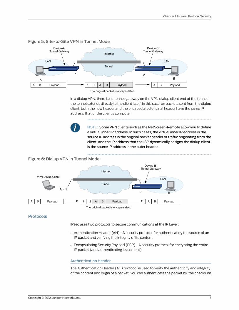
Figure 5: Site-to-Site VPN in Tunnel Mode
LAN
2
Internet
LAN
1B
Tunnel
Device-BTunnel Gateway
A
Device-ATunnel Gateway
The original packet is encapsulated.
A A A BBB 1 2Payload Payload Payload
In a dialup VPN, there is no tunnel gateway on the VPN dialup client end of the tunnel;
the tunnel extends directly to the client itself. In this case, on packets sent from the dialup
client, both the new header and the encapsulated original header have the same IP
address: that of the client’s computer.
NOTE: SomeVPNclients suchas theNetScreen-Remoteallowyou todefinea virtual inner IP address. In such cases, the virtual inner IP address is thesource IP address in the original packet header of traffic originating from theclient, and the IP address that the ISP dynamically assigns the dialup clientis the source IP address in the outer header.
Figure 6: Dialup VPN in Tunnel Mode
2
Internet
LAN
A A A BBB 1 2Payload Payload Payload
A = 1B
Tunnel
Device-BTunnel Gateway
VPN Dialup Client
The original packet is encapsulated.
Protocols
IPsec uses two protocols to secure communications at the IP Layer:
• Authentication Header (AH)—A security protocol for authenticating the source of an
IP packet and verifying the integrity of its content
• Encapsulating Security Payload (ESP)—A security protocol for encrypting the entire
IP packet (and authenticating its content)
Authentication Header
The Authentication Header (AH) protocol is used to verify the authenticity and integrity
of the content and origin of a packet. You can authenticate the packet by the checksum
7Copyright © 2012, Juniper Networks, Inc.
Chapter 1: Internet Protocol Security

calculated through a Hash Message Authentication Code (HMAC) using a secret key
and the MD5, SHA-1 or SHA-2 hash functions.
• MessageDigestversion5(MD5)—Algorithm that produces a 128-bit hash (also called
a digital signature ormessage digest) from a message of arbitrary length and a 16-byte
key. The resulting hash is used, like a fingerprint of the input, to verify content and
source authenticity and integrity.
• Secure Hash Algorithm-1 (SHA-1)—Algorithm that produces a 160-bit hash from a
message of arbitrary length and a 20-byte key. It is generally regarded as more secure
than MD5 because of the larger hashes it produces. Because the computational
processing is done in the ASIC, the performance cost is negligible.
• SecureHashAlgorithm-2(SHA-2)—Set of four algorithms named after their message
digest length (in bits)—SHA2-224, SHA2-256, SHA2-384, and SHA2-512. These
algorithms are generally regarded as more secure than SHA-1 because of the larger
hashes they produce. This release of ScreenOS supports the SHA2-256 hash algorithm.
The SHA2-256 algorithm produces a 256-bit hash from a message of arbitrary length
and a 32-byte key.
NOTE: Formore informationabout theMD5,SHA-1,andSHA2-256hashingalgorithms, refer to the following RFCs: (MD5) 1321, 2403; (SHA-1) 2404;(SHA2-256) 4753, 4868. For information about HMAC, refer to RFC 2104.
In the current release, ScreenOS supports transport mode with AH on thehigh-end systems for IPv4 packets only. This feature does not work if IPv6is enabled on the device.
Encapsulating Security Payload
The Encapsulating Security Payload (ESP) protocol provides a means for ensuring privacy
(encryption) and source authentication and content integrity (authentication). ESP in
tunnel mode encapsulates the entire IP packet (header and payload) and then appends
a new IP header to the now-encrypted packet. This new IP header contains the destination
address needed to route the protected data through the network.
With ESP, you can both encrypt and authenticate, encrypt only, or authenticate only. For
encryption, you can choose one of the following encryption algorithms:
• Data Encryption Standard (DES)—A cryptographic block algorithm with a 56-bit key.
• TripleDES(3DES)—A more powerful version of DES in which the original DES algorithm
is applied in three rounds, using a 168-bit key. DES provides a significant performance
savings but is considered unacceptable for many classified or sensitive material
transfers.
• Advanced Encryption Standard (AES)—An emerging encryption standard which,
when adopted by Internet infrastructures worldwide, will offer greater interoperability
with other network security devices. ScreenOS supports AES with 128-bit, 192-bit, and
256-bit keys.
Copyright © 2012, Juniper Networks, Inc.8
Virtual Private Networks

For authentication, you can use the MD5, SHA-1 or SHA2-256 algorithms.
NOTE: Even though it is possible to selectNULL for authentication, it hasbeen demonstrated that IPsecmight be vulnerable to attack under suchcircumstances. Therefore, it is inadvisable to selectNULL for authentication.
KeyManagement
Key distribution and management are critical to using VPNs successfully. IPsec supports
both manual and automatic key-distribution methods.
Manual Key
With manual key encryption, administrators at both ends of a tunnel configure all the
security parameters. This is a viable technique for small, static networks where the
distribution, maintenance, and tracking of keys are not difficult. However, safely distributing
manual-key configurations across great distances poses security issues. Aside from
passing a key face-to-face, you cannot be completely sure that the key has not been
compromised while in transit. Also, whenever you want to change the key, you are faced
with the same security issues as when you initially distributed it.
AutoKey IKE
When you need to create and manage numerous tunnels, you need a method that does
not require you to manually configure every element. IPsec supports the automated
generation and negotiation of keys and security associations using the Internet Key
Exchange (IKE) protocol. ScreenOS refers to such automated tunnel negotiation as
AutoKey IKE and supports AutoKey IKE with preshared keys and AutoKey IKE with
certificates.
AutoKey IKE with Preshared Keys
With AutoKey IKE which uses preshared keys to authenticate the participants in an IKE
session, each side must configure and securely exchange the preshared key in advance.
In this regard, the issue of secure key distribution is the same as that with manual keys.
However, once distributed, an autokey, unlike a manual key, can automatically change
its keys at predetermined intervals using the IKE protocol. Frequently changing keys
greatly improves security, and automatically doing so greatly reduces key-management
responsibilities. However, changing keys increases traffic overhead; therefore, doing so
too often can reduce data transmission efficiency.
NOTE: A preshared key is a key for both encryption and decryption, whichboth participants must possess before initiating communication.
AutoKey IKE with Certificates
When using certificates to authenticate the participants during an AutoKey IKE negotiation,
each side generates a public/private key pair (see “Public Key Cryptography” on page 35
) and acquires a certificate (see “Certificates and CRLs” on page 39). As long as the
9Copyright © 2012, Juniper Networks, Inc.
Chapter 1: Internet Protocol Security

issuing certificate authority (CA) is trusted by both sides, the participants can retrieve
the peer’s public key and verify the peer’s signature. There is no need to keep track of the
keys and SAs; IKE does so automatically.
NOTE: For examples of both Manual Key and AutoKey IKE tunnels, see“Site-to-Site Virtual Private Networks” on page 91.
Key Protection
Juniper Networks security devices protect VPN-persistent private keys against
unauthorized access and modification. By enabling the key protection feature, the security
device encrypts VPN persistent private keys, checks integrity of the key whenever the
key is used, and destroys the key memory with different key patterns in the system.
The following types of VPN private keys are encrypted:
• PKI private keys (DSA/RSA/ECDSA)
• IKE preshared keys and preshared key seeds
• VPN manual keys (keys generated from passwords)
All VPN manual keys and keys generated from passwords are encrypted from plaintext
to encrypted text using a master key (a hard-coded key). The same master key is used
to decrypt the encrypted key back to plaintext. You cannot access the master key if you
are accessing the system through any management interface. The AES (128-bit)
encryption algorithm is used to encrypt the keys. The security device uses the
single-parity-bit Error Detection Code (EDC) algorithm to detect key errors.
Enabling Key Protection
You can enable key protection through the WebUI or the CLI. The key protection feature
is disabled by default.
WebUI
Configuration > Admin > Management: Select Enable Key Protection, then click Apply.
CLI
set key protection enablesave
Security Associations
A security association (SA) is a unidirectional agreement between the VPN participants
regarding the methods and parameters to use in securing a communication channel. Full
bidirectional communication requires at least two SAs, one for each direction.
An SA groups together the following components for securing communications:
• Security algorithms and keys
• Protocol mode (transport or tunnel)
Copyright © 2012, Juniper Networks, Inc.10
Virtual Private Networks

• Key-management method (manual key or AutoKey IKE)
• SA lifetime
For outbound VPN traffic, the policy invokes the SA associated with the VPN tunnel. For
inbound traffic, the security device looks up the SA by using the following triplet:
• Destination IP
• Security protocol (AH or ESP)
• Security parameter index (SPI) value
Tunnel Negotiation
For a manual key IPsec tunnel, because all of the security association (SA) parameters
have been previously defined, there is no need to negotiate which SAs to use. In essence,
the tunnel has already been established. When traffic matches a policy using that manual
key tunnel or when a route involves the tunnel, the security device simply encrypts and
authenticates the data, as you determined, and forwards it to the destination gateway.
To establish an AutoKey IKE IPsec tunnel, two phases of negotiations are required:
• In Phase 1, the participants establish a secure channel in which to negotiate the IPsec
SAs.
• In Phase 2, the participants negotiate the IPsec SAs for encrypting and authenticating
the ensuing exchanges of user data.
NOTE: Juniper Networks security devices support the newer version of theIKE protocol known as IKEv2. For more information about IKEv2 and howsecurity devices establish security associations (SAs) using the IKEv2protocol, see “IKE Version 2” on page 20.
Phase 1
Phase 1 of an AutoKey IKE tunnel negotiation consists of the exchange of proposals for
how to authenticate and secure the channel. The exchange can be in one of two modes:
aggressive or main. Using either mode, the participants exchange proposals for acceptable
security services such as:
• Encryption algorithms (DES and 3DES) and authentication algorithms (MD5, SHA-1
or SHA2-256). For more information about these algorithms, see “Protocols” on page 7.
• A Diffie-Hellman group (see “Diffie-Hellman Exchange” on page 13).
• Preshared key or RSA/DSA certificates (see “AutoKey IKE” on page 9).
A successful Phase 1 negotiation concludes when both ends of the tunnel agree to accept
at least one set of the Phase 1 security parameters proposed and then process them.
Juniper Networks security devices support up to four proposals for Phase 1 negotiations,
11Copyright © 2012, Juniper Networks, Inc.
Chapter 1: Internet Protocol Security

allowing you to define how restrictive a range of security parameters for key negotiation
you will accept.
The predefined Phase 1 proposals that ScreenOS provides are as follows:
• Standard: pre-g2-aes128-sha and pre-g2-3des-sha
• Compatible:pre-g2-3des-sha, pre-g2-3des-md5, pre-g2-des-sha, and pre-g2-des-md5
• Basic: pre-g1-des-sha and pre-g1-des-md5
You can also define custom Phase 1 proposals.
Main and Aggressive Modes
Phase 1 can take place in either main or aggressive mode. The two modes are described
below.
Mainmode: The initiator and recipient send three two-way exchanges (six messages
total) to accomplish the following services:
• First exchange (messages 1 and 2): Propose and accept the encryption and
authentication algorithms.
• Second exchange (messages 3 and 4): Execute a DH exchange, and the initiator and
recipient each provide a pseudo-random number.
• Third exchange (messages 5 and 6): Send and verify their identities.
The information transmitted in the third exchange of messages is protected by the
encryption algorithm established in the first two exchanges. Thus, the participants’
identities are not transmitted in the clear.
Aggressivemode: The initiator and recipient accomplish the same objectives, but only
in two exchanges, with a total of three messages:
• First message: The initiator proposes the SA, initiates a DH exchange, and sends a
pseudo-random number and its IKE identity.
• Second message: The recipient accepts the SA; authenticates the initiator; and sends
a pseudo-random number, its IKE identity, and, if using certificates, the recipient’s
certificate.
• Third message: The initiator authenticates the recipient, confirms the exchange, and,
if using certificates, sends the initiator’s certificate.
Because the participants’ identities are exchanged in the clear (in the first two messages),
aggressive mode does not provide identity protection.
NOTE: When a dialup VPN user negotiates an AutoKey IKE tunnel with apreshared key, aggressivemodemust be used. Note also that a dialup VPNuser can use an email address, a fully qualified domain name (FQDN), or anIP address as its IKE ID. A dynamic peer can use either an email address orFQDN, but not an IP address.
Copyright © 2012, Juniper Networks, Inc.12
Virtual Private Networks
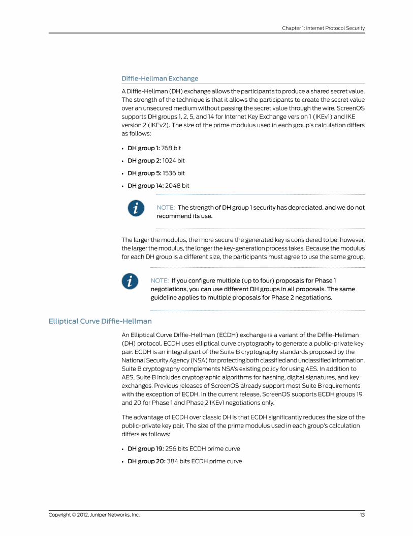
Diffie-Hellman Exchange
A Diffie-Hellman (DH) exchange allows the participants to produce a shared secret value.
The strength of the technique is that it allows the participants to create the secret value
over an unsecured medium without passing the secret value through the wire. ScreenOS
supports DH groups 1, 2, 5, and 14 for Internet Key Exchange version 1 (IKEv1) and IKE
version 2 (IKEv2). The size of the prime modulus used in each group’s calculation differs
as follows:
• DH group 1: 768 bit
• DH group 2: 1024 bit
• DH group 5: 1536 bit
• DH group 14: 2048 bit
NOTE: The strength of DH group 1 security has depreciated, andwe do notrecommend its use.
The larger the modulus, the more secure the generated key is considered to be; however,
the larger the modulus, the longer the key-generation process takes. Because the modulus
for each DH group is a different size, the participants must agree to use the same group.
NOTE: If you configuremultiple (up to four) proposals for Phase 1negotiations, you can use different DH groups in all proposals. The sameguideline applies tomultiple proposals for Phase 2 negotiations.
Elliptical Curve Diffie-Hellman
An Elliptical Curve Diffie-Hellman (ECDH) exchange is a variant of the Diffie-Hellman
(DH) protocol. ECDH uses elliptical curve cryptography to generate a public-private key
pair. ECDH is an integral part of the Suite B cryptography standards proposed by the
National Security Agency (NSA) for protecting both classified and unclassified information.
Suite B cryptography complements NSA’s existing policy for using AES. In addition to
AES, Suite B includes cryptographic algorithms for hashing, digital signatures, and key
exchanges. Previous releases of ScreenOS already support most Suite B requirements
with the exception of ECDH. In the current release, ScreenOS supports ECDH groups 19
and 20 for Phase 1 and Phase 2 IKEv1 negotiations only.
The advantage of ECDH over classic DH is that ECDH significantly reduces the size of the
public-private key pair. The size of the prime modulus used in each group’s calculation
differs as follows:
• DH group 19: 256 bits ECDH prime curve
• DH group 20: 384 bits ECDH prime curve
13Copyright © 2012, Juniper Networks, Inc.
Chapter 1: Internet Protocol Security
NOTE: You cannot configure ECDH groups on IKEv2 gateways. If youattempt to configure a Phase 1 or 2 proposal that uses an ECDH group, thesecurity device generates the following error: ECDH groups are notsupported by IKEv2. Use Oakley group 1, 2, 5, or 14 for IKEv2 negotiations.
Phase 2
After the participants have established a secure and authenticated channel, they proceed
through Phase 2, in which they negotiate the SAs to secure the data to be transmitted
through the IPsec tunnel.
Like the process for Phase 1, the participants exchange proposals to determine which
security parameters to employ in the SA. A Phase 2 proposal also includes a security
protocol—either Encapsulating Security Payload (ESP) or Authentication Header
(AH)—and selected encryption and authentication algorithms. The proposal can also
specify a DH group, if Perfect Forward Secrecy (PFS) is desired.
Regardless of the mode used in Phase 1, Phase 2 always operates in quick mode and
involves the exchange of three messages.
Juniper Networks security devices support up to four proposals for Phase 2 negotiations,
allowing you to define how restrictive a range of tunnel parameters you will accept.
ScreenOS also provides a replay protection feature. Use of this feature does not require
negotiation because packets are always sent with sequence numbers. You simply have
the option of checking or not checking the sequence numbers. (For more information
about replay protection, see “Replay Protection” on page 15.)
The predefined Phase 2 proposals that ScreenOS provides are as follows:
• Standard: g2-esp-3des-sha and g2-esp-aes128-sha
• Compatible: nopfs-esp-3des-sha, nopfs-esp-3des-md5, nopfs-esp-des-sha, and
nopfs-esp-des-md5
• Basic: nopfs-esp-des-sha and nopfs-esp-des-md5
You can also define custom Phase 2 proposals.
In Phase 2, the peers also exchange proxy IDs. A proxy ID is a three-part tuple consisting
of local IP address–remote IP address–service. The proxy ID for both peers must match,
which means that the service specified in the proxy ID for both peers must be the same,
and the local IP address specified for one peer must be the same as the remote IP address
specified for the other peer.
NOTE: Phase2negotiations for IPv6supportNetscreenRedundancyProtocol(NSRP).
Copyright © 2012, Juniper Networks, Inc.14
Virtual Private Networks

The CREATE_CHILD_SA exchange in an IKEv2 exchange corresponds to the Phase 2
negotiations in IKEv1. For more information, see “Initial Exchanges” on page 20.
Perfect Forward Secrecy
Perfect Forward Secrecy (PFS) is a method for deriving Phase 2 keys independent from
and unrelated to the preceding keys. Alternatively, the Phase 1 proposal creates the key
(the SKEYID_d key) from which all Phase 2 keys are derived. The SKEYID_d key can
generate Phase 2 keys with a minimum of CPU processing. Unfortunately, if an
unauthorized party gains access to the SKEYID_d key, all your encryption keys are
compromised.
PFS addresses this security risk by forcing a new Diffie-Hellman key exchange to occur
for each Phase 2 tunnel. Using PFS is thus more secure, although the rekeying procedure
in Phase 2 might take slightly longer with PFS enabled.
Replay Protection
A replay attack occurs when somebody intercepts a series of packets and uses them
later either to flood the system, causing a denial of service (DoS), or to gain entry to the
trusted network. The replay-protection feature enables security devices to check every
IPsec packet to see if it has been received previously. If packets arrive outside a specified
sequence range, the security device rejects them.
IKE and IPsec Packets
An IPsec VPN tunnel consists of two major elements:
• Tunnel Setup: The peers first establish security associations (SAs), which define the
parameters for securing traffic between themselves. The admins at each end can
define the SAs manually, or the SAs can be defined dynamically through IKE Phase 1
and Phase 2 negotiations. Phase 1 can occur in either main or aggressive mode. Phase 2
always occurs in quick mode.
• Applied Security: IPsec protects traffic sent between the two tunnel endpoints by
using the security parameters defined in the SAs that the peers agreed to during the
tunnel setup. IPsec can be applied in one of two modes—transport or tunnel. Both
modes support the two IPsec protocols—Encapsulating Security Payload (ESP) and
Authentication Header (AH).
For an explanation of the packet processing that occurs during the IKE and IPsec stages
of a VPN tunnel, see “IKE Packets” on page 15 and “IPsec Packets” on page 18. These
sections show the packet headers for IKE and IPsec, respectively.
IKE Packets
When a clear-text packet arrives at the security device that requires tunneling and no
active Phase 2 SA exists for that tunnel, the security device begins IKE negotiations (and
drops the packet). The source and destination addresses in the IP packet header are
those of the local and remote IKE gateways, respectively. In the IP packet payload, there
is a UDP segment encapsulating an Internet Security Association and Key Management
15Copyright © 2012, Juniper Networks, Inc.
Chapter 1: Internet Protocol Security

Protocol (ISAKMP), or IKE, packet. The format for IKE packets is the same for Phase 1
and Phase 2.
NOTE: When the initial IP packet is dropped, the source host resends it.Typically, by the time the second packet reaches the security device, IKEnegotiations are complete and the security device protects it—and allsubsequent packets in the session—with IPsec before forwarding it.
Figure 7: IKE Packet for Phases 1 and 2
The Next Payload field contains a number indicating one of the following payload types:
• 0002—SA Negotiation Payload: contains a definition for a Phase 1 or Phase 2 SA.
• 0004—Proposal Payload: can be a Phase 1 or Phase 2 proposal.
• 0008—Transform Payload: the transform payload gets encapsulated in a proposal
payload which gets encapsulated in an SA payload.
Copyright © 2012, Juniper Networks, Inc.16
Virtual Private Networks

• 0010—Key Exchange (KE) Payload: contains information necessary to perform a key
exchange, such as a Diffie-Hellman public value.
• 0020—Identification (IDx) Payload.
• In Phase 1, IDii indicates the initiator ID, and IDir indicates the responder ID.
• In Phase 2, IDui indicates the user initiator, and IDur indicates the user responder.
The IDs are IKE ID types such as FQDN, U-FQDN, IP address, and ASN.1_DN.
• 0040—Certificate (CERT) Payload.
• 0080—Certificate Request (CERT_REQ) Payload.
• 0100—Hash (HASH) Payload: contains the digest output of a particular hash function.
• 0200—Signature (SIG) Payload: contains a digital signature.
• 0400—Nonce (Nx) Payload: contains some pseudo-random information necessary
for the exchange).
• 0800—Notify Payload.
• 1000—ISAKMP Delete Payload.
• 2000—Vendor ID (VID) Payload: can be included anywhere in Phase 1 negotiations.
ScreenOS uses it to mark support for Network Address Translation-Traversal (NAT-T).
Each ISAKMP payload begins with the same generic header, as shown in Figure 8 on
page 17.
Figure 8: Generic ISAKMPPayload Header
There can be multiple ISAKMP payloads chained together, with each subsequent payload
type indicated by the value in the Next Header field. A value of 0000 indicates the last
ISAKMP payload. See Figure 9 on page 18 for an example.
17Copyright © 2012, Juniper Networks, Inc.
Chapter 1: Internet Protocol Security

Figure 9: ISAKMPHeader with Generic ISAKMPPayloads
IPsec Packets
After IKE negotiations complete and the two IKE gateways have established Phase 1 and
Phase 2 security associations (SAs), the security device applies IPsec protection to
subsequent clear-text IP packets that hosts behind one IKE gateway send to hosts behind
the other gateway (assuming that policies permit the traffic). If the Phase 2 SA specifies
the Encapsulating Security Protocol (ESP) in tunnel mode, the packet looks like the one
shown below. The security device adds two additional headers to the original packet
that the initiating host sends.
NOTE: For information about ESP, see “Encapsulating Security Payload” onpage 8. For information about tunnel mode, see “Tunnel Mode” on page 6.
Figure 10: IPsec Packet—Encapsulating Security Payload in Tunnel Mode
As shown in Figure 10 on page 18, the packet that the initiating host constructs includes
the payload, the TCP header, and the inner IP header (IP1).
The outer IP header (IP2), which the security device adds, contains the IP address of the
remote gateway as the destination IP address and the IP address of the local security
device as the source IP address. The security device also adds an ESP header between
the outer and inner IP headers. The ESP header contains information that allows the
remote peer to properly process the packet when it receives it. This is illustrated in Figure
11 on page 19.
Copyright © 2012, Juniper Networks, Inc.18
Virtual Private Networks

Figure 11: Outer IP Header (IP2) and ESPHeader
The Next Header field indicates the type of data in the payload field. In tunnel mode, this
value is 4, indicating IP-in-IP. If ESP is applied in transport mode, this value indicates a
Transport Layer protocol such as 6 for TCP or 17 for UDP.
19Copyright © 2012, Juniper Networks, Inc.
Chapter 1: Internet Protocol Security
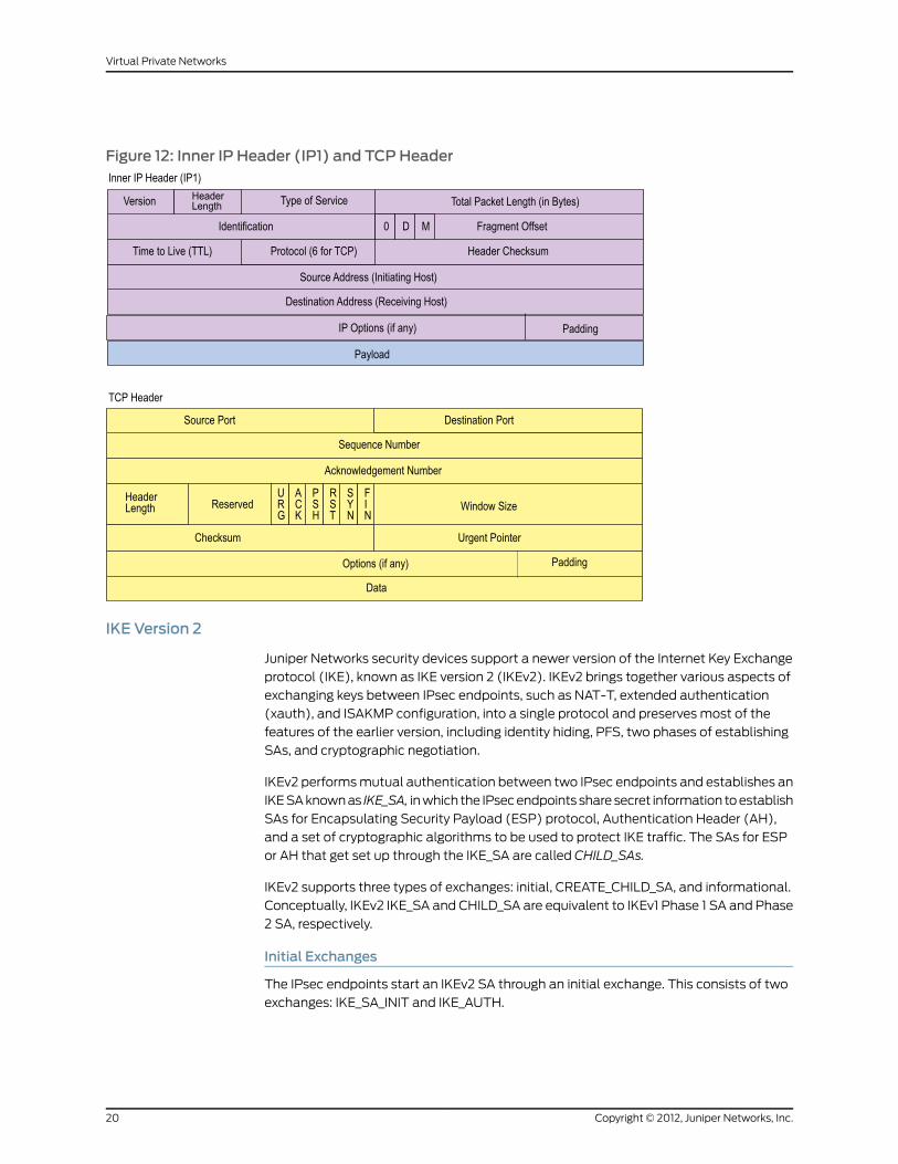
Figure 12: Inner IP Header (IP1) and TCPHeader
IKE Version 2
Juniper Networks security devices support a newer version of the Internet Key Exchange
protocol (IKE), known as IKE version 2 (IKEv2). IKEv2 brings together various aspects of
exchanging keys between IPsec endpoints, such as NAT-T, extended authentication
(xauth), and ISAKMP configuration, into a single protocol and preserves most of the
features of the earlier version, including identity hiding, PFS, two phases of establishing
SAs, and cryptographic negotiation.
IKEv2 performs mutual authentication between two IPsec endpoints and establishes an
IKE SA known as IKE_SA, in which the IPsec endpoints share secret information to establish
SAs for Encapsulating Security Payload (ESP) protocol, Authentication Header (AH),
and a set of cryptographic algorithms to be used to protect IKE traffic. The SAs for ESP
or AH that get set up through the IKE_SA are called CHILD_SAs.
IKEv2 supports three types of exchanges: initial, CREATE_CHILD_SA, and informational.
Conceptually, IKEv2 IKE_SA and CHILD_SA are equivalent to IKEv1 Phase 1 SA and Phase
2 SA, respectively.
Initial Exchanges
The IPsec endpoints start an IKEv2 SA through an initial exchange. This consists of two
exchanges: IKE_SA_INIT and IKE_AUTH.
Copyright © 2012, Juniper Networks, Inc.20
Virtual Private Networks

IKE_SA_INIT Exchange
An IKE_SA_INIT exchange negotiates security suites, establishes the IKE_SA, and generates
the SKEYSEED from which all keys are derived for the IKE_SA. Separate keys are computed
for each direction. The initiator sends the following:
• HDR—Initiator’s IKE header. The header contains the security parameter indexes (SPIs),
version, and flags.
• SAi1—Cryptographic algorithms the initiator supports for the IKE_SA.
• KEi—Initiator’s Diffie-Hellman value
• Ni—Initiator’s nonce
The responder sends the response to the initiator request with the following:
• HDR—Responder’s header
• SAr1—Cryptographic algorithms the responder supports for the IKE_SA.
• KEr—Responder’s Diffie-Hellman value
• Nr—Responder’s nonce
• [CERTREQ]—[Optional] Certificate request
IKE_AUTH Exchange
The IKE_AUTH exchange authenticates IKE endpoints and establishes the CHILD_SA.
This exchange consists of a single request/response pair. The initiator starts using the
new CHILD_SA immediately after receiving the responder's response; similarly, the
responder starts using the new CHILD_SA immediately after sending the response to the
initiator.
In the endpoint-to-security gateway scenario where the endpoint is an Internet remote
access client (IRAC) and the security gateway is an Internet remote access server (IRAS),
the IRAC needs an IP address associated with the security gateway to establish a
connection with the protected subnet through an IPSec tunnel. In support of this, IKEv2
enables the IRAC to request an IP address owned by the IRAS for use in the secure
connection. The IRAC requests an IP address by sending a configuration payload (CP)
request in the IKE_AUTH exchange. The IRAS selects an IP address from the address
pool it maintains or from the external RADIUS server and sends it to the IRAC. The assigned
IP address is freed when its associated IKE_SA lifetime ends. CP also supports to assign
DNS and WINS servers addresses. The IRAC gets the DNS and WINS servers addresses
from the IRAS itself or from an external RADIUS server.
NOTE: IKEv2 CP is not supported for IPv6 addresses.
All messages following the initial exchange are cryptographically protected using the
cryptographic algorithms and keys negotiated in the first two messages of the key
exchange. These subsequent messages use the syntax of the encrypted payload. During
the IKE_AUTH exchange, the endpoints exchange the following:
21Copyright © 2012, Juniper Networks, Inc.
Chapter 1: Internet Protocol Security
• HDR—Initiator’s header
• IDi—Initiator’s ID
• [CERT]—[Optional] Certificate
• [CERTREQ]—[Optional] Certificate Request
• IDr—Responder’s ID
• AUTH—Authenticates the previous message and the initiator’s identity
• CP (CFG_REQUEST)—[Optional] Exchanges the configuration information between
the IKE peers
• SAi2—Initiator’s SA
• TSi—Initiator’s traffic selector
• TSr—Responder’s traffic selector
The responder sends the following response:
• HDR—Responder’s header
• IDr—Initiator’s ID
• [CERT]—[Optional] Certificate
• AUTH—Authenticates the previous message and the initiator’s identity
• CP (CFG_REPLY)—[Optional] Exchanges the configuration information between the
IKE peers
• SAr2—Responder's SA
• TSi—Initiator’s traffic selector
• TSr—Responder’s traffic selector
Of these messages, except the Header, all other payload are encrypted with the secret
key generated by the endpoints.
Example: Configuring IRAC and IRAS to Get an IP Address from a Local and ExternalDatabases
WebUI
1. Configuring IRAS to Get an IP Address from a Local IP Pool:
VPN > AutoKey Advanced > MODECFG Profile: Enter the following, then click New:
Profile Name: testIP Pool: ippool_testDNS IP1: 10.0.0.1IP2: 10.0.0.2WINS IP1: 10.0.0.3IP2: 10.0.0.4
VPNs > AutoKey Advanced > Gateway > EAP > MODECFG Enable: Perform the
following actions, then click OK.
Copyright © 2012, Juniper Networks, Inc.22
Virtual Private Networks

Server: selectAction: select Add RouteInformation Origin: select Use Local DNSProfile: test
2. Configuring IRAC to Get an IP address from a Local IP Pool:
VPNs > AutoKey Advanced > Gateway > EAP > MODECFG Enable: selectClient, then
click OK.
CLI
1. Configuring IRAS to Get an IP Address from a Local IP Pool:
set ippool ippool_test 10.0.0.5 10.0.0.10set ikemodecfg profile name testset ikemodecfg profile test ippool ippool_testset ikemodecfg profile test dns1 10.0.0.1set ike modecfg profile test dns2 10.0.0.2set ikemodecfg profile test wins1 10.0.0.3set ikemodecfg profile test wins2 10.0.0.4set ike gateway ikev2 gate_test modecfg server profile test
2. Configuring IRAC to Get an IP Address from a Local IP Pool:
set ike gateway ikev2 gate_test modecfg client
WebUI
1. Configuring IRAS toanGetan IPAddress fromanEAPandExternalRADIUSServer:
Configuation > Auth > Auth Servers > New: Enter the following, then click OK.
Name: 202.0.0.1Account Type: IKEv2EAPRadius: selectRadius Port: 1812Shared Secret: 1111
VPN >AutoKey Advanced >Gateway > EAP and perform the following actions:
IKEv2 EAP Authentication: (select)Authenticator: (select)Send ID: (select)Query Config:
Select VPN >AutoKey Advanced >Gateway >EAP > New> IKEv2 Advanced and
perform the following:
IKEv2 Auth Method: (select)Self: select rsa-sigPeer: select eap
VPNs > AutoKey Advanced > Gateway > EAP > MODECFG Enable: Perform the
following actions, then click OK.
Server:Action: select Add RouteInformation Origin: select Use Local DNSProfile: test
23Copyright © 2012, Juniper Networks, Inc.
Chapter 1: Internet Protocol Security

2. Configuring IRAC to Get an IP Address from an EAP and External RADIUS Server:
Select VPN >AutoKey Advanced >Gateway >EAP and perform the following actions:
IKEv2 EAP Authentication: (select)Supplicant: (select)User Name: tempPassword: temp
Select VPN >AutoKey Advanced >Gateway >EAP > New> IKEv2 > Advanced and
perform the following:
IKEv2 Auth Method: (select)Self: rsa-sigPeer:eap
VPNs > AutoKey Advanced > Gateway > EAP > MODECFG Enable: SelectClient, then
click OK.
CLI
1. Configuring IRAS to Get an IP Address from an EAP and External RADIUS Server:
set auth-server test server-name 202.0.0.1set auth-server test account-type eap-ikev2set auth-server test radius port 1812set auth-server test radius secret 1111set ike gateway ikev2 gate_test eap authenticator passthrough test send-id-reqquery-config
set ike gateway ikev2 "v2-gw3" auth-method self rsa-sig peer eapset ike gateway ikev2 gate_test modecfg server
2. Configuring IRAC to Get an IP Address from an EAP and External Radius Server:
set ike gateway ikev2 gate_test eap supplicant md5 username temp password tempset ike gateway ikev2 gate_test eap supplicant md5 username temp password tempset ike gateway ikev2 gate_test modecfg client
Example: Verifying if IRAS and IRAC receives the IP address
1. To verify if IRAS receives the IP address, use the get interface tunnel inter_tun CLI for
route-based VPN as given below.
ssg5-serial-> get int t.1…tun.1 88.1.1.5/32 Untrust N/A - R -## 2008-11-12 10:43:37 : IKE<20.1.1.2> ****** Recv packet if <ethernet0/0> of vsys<Root> ******
## 2008-11-12 10:43:37 : IKE<20.1.1.2> Catcher: get 252 bytes. src port 500## 2008-11-12 10:43:37 : IKE<0.0.0.0 > found existing ike sa node 29319a8## 2008-11-12 10:43:37 : IKE<20.1.1.2 > Search IKE_SA table, found 29319a8## 2008-11-12 10:43:37 : Duplicated pkt checking ...## 2008-11-12 10:43:37 : len in wind 288, hash in wind 1606591330, len 252, hash 0## 2008-11-12 10:43:37 : hash in SA is a1dd69b2, len 252##2008-11-12 10:43:37 : IKE<0.0.0.0 > payload len 12, next payload type<39><AUTH>## 2008-11-12 10:43:37 : IKE<0.0.0.0 > payload len 28, next payload type<47><CFG>## 2008-11-12 10:43:37 : IKE<0.0.0.0 > payload len 12, next payload type<33><SA>##2008-11-12 10:43:37 : IKE<0.0.0.0>payload len80,nextpayload type<41><NOTIF>## 2008-11-12 10:43:37 : IKE<0.0.0.0 > payload len 8, next payload type<41><NOTIF>
Copyright © 2012, Juniper Networks, Inc.24
Virtual Private Networks

## 2008-11-12 10:43:37 : IKE<0.0.0.0 > payload len 8, next payload type<44><TSi>## 2008-11-12 10:43:37 : IKE<0.0.0.0 > payload len 24, next payload type<45><TSr>##2008-11-12 10:43:37 : IKE<0.0.0.0>payload len24,nextpayloadtype<0><unknown>## 2008-11-12 10:43:37 : start seq no is 1, avil seq no is 0, win size is 1## 2008-11-12 10:43:37 : return seq no 1 as Responder## 2008-11-12 10:43:37 : start seq no is 2, avil seq no is 0, win size is 1##2008-11-12 10:43:37 : IKE<0.0.0.0> ISAKMPmsg: ver 20, len224,nxp35exch35[IKESA AUTH], flag 08(I(1) R(0) V(0)),
...## 2008-11-12 10:43:37 : Processing CP## 2008-11-12 10:43:37 : Receive CP req: ip 0.0.0.0...## 2008-11-12 10:43:37 : Construct CP reply## 2008-11-12 10:43:37 : Construct CP reply: ip addr 88.1.1.5
2. To verify if IRAC receives the IP address, use debug ike detail for policy-based VPN as
given below.
debug ike detail## 2008-11-12 11:10:27 : Enter IKEv2 init IKE_AUTH post processing, state 0## 2008-11-12 11:10:27 : Constructing IKE_AUTH request## 2008-11-12 11:10:27 : construct_ike_auth, send-auth 1 send_cp 1## 2008-11-12 11:10:27 : Construct IKEv2 header.## 2008-11-12 11:10:27 : Msg header built (next payload #0)2008-11-12 11:10:27 : ID type 1, len 4.## 2008-11-12 11:10:27 : initiator auth data len = 14.## 2008-11-12 11:10:27 : Construct [CP] request: ip 0.0.0.0##2008-11-12 11:10:27 : Construct [SA] (CHILD_SA) request for IKEv2. conn->new_spi_r= 29504c0, &conn->new_spi_r = 29504c0.
## 2008-11-12 11:10:27 : Construct [SA] (CHILD_SA) request for IKEv2. spi = 43242975…## 2008-11-12 11:10:27 : IKE<20.1.1.1> ****** Recv packet if <ethernet0/0> of vsys<Root> ******
## 2008-11-12 11:10:27 : IKE<20.1.1.1> Catcher: get 220 bytes. src port 500## 2008-11-12 11:10:27 : IKE<0.0.0.0 > found existing ike sa node 28dbbe4## 2008-11-12 11:10:27 : IKE<20.1.1.1 > Search IKE_SA table, found 28dbbe4.## 2008-11-12 11:10:27 : IKE<0.0.0.0 > payload len 12, next payload type<39><AUTH>## 2008-11-12 11:10:27 : IKE<0.0.0.0 > payload len 28, next payload type<47><CFG>## 2008-11-12 11:10:27 : IKE<0.0.0.0 > payload len 16, next payload type<33><SA>## 2008-11-12 11:10:27 : IKE<0.0.0.0 > payload len 40, next payload type<41><NOTIF>## 2008-11-12 11:10:27 : IKE<0.0.0.0 > payload len 8, next payload type<41><NOTIF>## 2008-11-12 11:10:27 : IKE<0.0.0.0 > payload len 8, next payload type<44><TSi>## 2008-11-12 11:10:27 : IKE<0.0.0.0 > payload len 24, next payload type<45><TSr>##2008-11-12 11:10:27 : IKE<0.0.0.0>payload len24,nextpayload type<0><unknown<## 2008-11-12 11:10:27 : start seq no is 1, avil seq no is 2, win size is 1## 2008-11-12 11:10:27 : return seq no 1 as Initiator## 2008-11-12 11:10:27 : start seq no is 2, avil seq no is 2, win size is 1## 2008-11-12 11:10:27 : IKE<0.0.0.0 > ISAKMPmsg: ver 20, len 188, nxp 36 exch 35[IKESA AUTH], flag 20(I(0) R(1) V(0)), msgid 1
...## 2008-11-12 11:10:27 : Processing CP## 2008-11-12 11:10:27 : Receive CP payload: ip 88.1.1.5.##2008-11-12 11:10:27 : ikmpd.c ike_if_ip_post_change_callback6383, interface tunnel.1pre change callabck for ike
## 2008-11-12 11:10:27 : update ike local addr sent: 3368## 2008-11-12 11:10:27 : postprocess_ike_auth_resp: assign IP 88.1.1.5 fromCP
25Copyright © 2012, Juniper Networks, Inc.
Chapter 1: Internet Protocol Security

CREATE_CHILD_SA Exchange
After the IPsec endpoints complete the initial exchanges, either endpoint can initiate the
CREATE_CHILD_SA. This exchange rekeys a CHILD_SA or IKE_SA. This exchange consists
of a single request/response pair and was referred to as a Phase 2 exchange in IKEv1.
All messages following the initial exchange are cryptographically protected using the
cryptographic algorithms and keys negotiated in the first two messages of the IKE.
Informational Exchanges
IKEv2 uses informational exchanges to send and receive control messages, including
dead peer detection (DPD).
Enabling IKEv2 on a Security Device
You can configure an existing IKEv1 gateway to support IKEv2. Such a converted gateway
configuration functions only with IKEv2 peers, not IKEv1. When you configure your security
device to support IKEv2, you should note the following differences between IKEv1 and
IKEv2:
• Unlike IKEv1, where the IPsec endpoints negotiate the Diffie-Hellman (DH) group before
agreeing on the DH group number, the IKEv2 initiator sends the DH group number in
the first message of the IKE_INIT_SA exchange. If the initiator has multiple DH group
proposals in its SA payload, the DH group that the initiator sends may not match the
DH group the responder expects. In such cases, the responder notifies the initiator with
the expected DH group number. The initiator responds to this message with the correct
DH group number and restarts the IKE_INIT_SA exchange.
• The two endpoints in an IKEv2 SA do not negotiate the IKE_SA and CHILD_SA lifetimes;
each endpoint can have its own lifetime. The endpoint with the shorter lifetime will
rekey before the current IKE_SA or CHILD_SA expires (by default, 10 seconds earlier
for IKE_SA and 60 seconds earlier for CHILD_SA), as long as the connection between
the endpoints still needs this IKE_SA or CHILD_SA. A CHILD_SA is considered no longer
needed when there has been no traffic since the last rekey or the SA has timed out. An
IKE_SA is no longer needed when all its CHILD_SAs are no longer needed.
• Authentication methods between the two negotiating IKE peers can be different; the
endpoints do not negotiate the authentication methods.
• All CHILD_SAs close if their parent IKE_SA is closed.
• The two endpoints maintain only one IKE_SA; all other exchanges are carried out
through CHILD_SAs.
Example: Configuring an IKEv2 Gateway
In the example shown in Figure 13 on page 27, you create two VPN tunnels that use IKEv2
for automatic generation and negotiation of keys and security associations (SAs). These
tunnels provide a secure connection between the two devices - Device B and Device A.
A policy-based VPN is configured on Device A, while a route-based VPN is configured on
Device B. For the Phase 1 and Phase 2 security levels, you specify standard and basic
predefined proposals, respectively, on both the devices.
Copyright © 2012, Juniper Networks, Inc.26
Virtual Private Networks
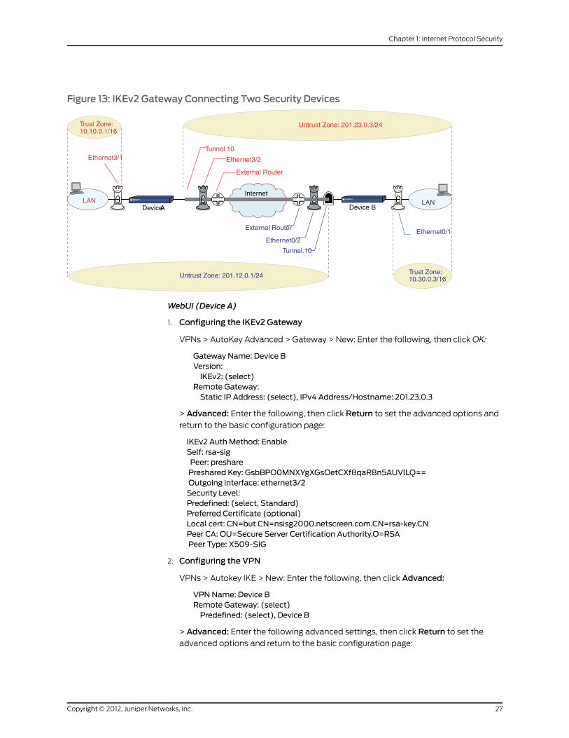
Figure 13: IKEv2 Gateway Connecting Two Security Devices
Untrust Zone: 201.23.0.3/24
Internet
Trust Zone:10.10.0.1/16
Untrust Zone: 201.12.0.1/24
LAN LAN
Trust Zone:10.30.0.3/16
Ethernet3/1
Ethernet0/1
Ethernet3/2
External Router
Tunnel.10
Tunnel.10
Ethernet0/2
External Router
DeviceA Device B
WebUI (Device A)
1. Configuring the IKEv2 Gateway
VPNs > AutoKey Advanced > Gateway > New: Enter the following, then click OK:
Gateway Name: Device BVersion:IKEv2: (select)
Remote Gateway:Static IP Address: (select), IPv4 Address/Hostname: 201.23.0.3
> Advanced: Enter the following, then click Return to set the advanced options and
return to the basic configuration page:
IKEv2 Auth Method: EnableSelf: rsa-sigPeer: presharePreshared Key: GsbBPO0MNXYgXGsOetCXf8qaR8n5AUVlLQ==Outgoing interface: ethernet3/2Security Level:Predefined: (select, Standard)Preferred Certificate (optional)Local cert: CN=but CN=nsisg2000.netscreen.com.CN=rsa-key.CNPeer CA: OU=Secure Server Certification Authority.O=RSAPeer Type: X509-SIG
2. Configuring the VPN
VPNs > Autokey IKE > New: Enter the following, then click Advanced:
VPNName: Device BRemote Gateway: (select)Predefined: (select), Device B
> Advanced: Enter the following advanced settings, then click Return to set the
advanced options and return to the basic configuration page:
27Copyright © 2012, Juniper Networks, Inc.
Chapter 1: Internet Protocol Security

Security LevelPredefined: (select, Basic)
3. Configuring the Route
Network > Routing > Routing Entries > Configuration: Enter the following, then click
OK:
Virtual Router name: untrust-vrIP Address / Netmask: 10.30.0.3/16Next Hop: Gateway (select)Interface: ethernet3/2
4. Creating Policies
Policy > Policies (From: Untrust, To: Trust) New: Enter the following, then click OK:
Source Address:New Address: 10.30.0.3/16
Destination Address:New address: 10.10.0.1/16
Service: (select), AnyAction: (select), TunnelTunnel: (select), Device B
Policy > Policies (From: Trust, To: Untrust) New: Enter the following, then click OK:
Source Address:New Address: 10.10.0.1/16
Destination Address:New address: 10.30.0.3/16
Service: (select), AnyAction: (select), TunnelTunnel: (select), Device B
WebUI (Device B)
1. Configuring the IKEv2 Gateway
VPNs > AutoKey Advanced > Gateway > New: Enter the following, then click OK:
Gateway Name: Device AVersion:IKEv2: (select)
Remote Gateway:Static IP Address: (select), IPv4 Address/Hostname: 201.12.0.1
> Advanced: Enter the following, then click Return to set the advanced options and
return to the basic configuration page:
IKEv2 Auth Method: EnableSelf: presharePeer: rsa-sigPreshared Key: 3to5BAFpNn3thBsncQCmBYF5ThnQVfMlEQ==Outgoing interface: ethernet0/2
Security Level:Predefined: (select, Standard)
Preferred Certificate (optional)Local cert: None
Copyright © 2012, Juniper Networks, Inc.28
Virtual Private Networks

Peer CA: CN=netscreen.OU=qaPeer Type: X509-SIG
2. Configuring the Tunnel Interface
Network > Interfaces > New: Enter the following, then click OK:
Tunnel Interface Name: tunnel.10Zone (VR): Untrust (trust-vr)Unnumbered: (select)Interface: ethernet0/2 (trust-vr)
3. Configuring the VPN and Proxy-ID
VPNs > Autokey IKE > New: Enter the following, then click Advanced:
VPNName: Device ARemote Gateway: (select)Predefined: (select), Device A
> Advanced: Enter the following advanced settings, then click Return to set the
advanced options and return to the basic configuration page:
Security LevelPredefined: (select, Basic)
Bind to: Tunnel Interface (select): Select tunnel.10, Untrust-Tun from the drop-downlistProxy-ID: (select)Local IP / Netmask: 10.30.0.0/16Remote IP / Netmask: 10.10.0.0/16Service: ANY
4. Configuring the Route
Network > Routing > Routing Entries > Configuration: Enter the following, then click
OK:
Virtual Router name: trust-vrIP Address / Netmask: 10.10.0.1/16Next Hop: Gateway (select)Interface: tunnel.10
CLI (Device A)
1. Configuring Addresses
set address trust 10.10.0.1 10.10.0.1/16set address untrust 10.30.0.3 10.30.0.3/16
2. Configuring the IKEv2 Gateway
set ike gateway ikev2 "DeviceB"address 201.23.0.3 outgoing-interface "ethernet3/2"preshare "GsbBPO0MNXYgXGsOetCXf8qaR8n5AUVILQ==" proposal "standard"set ike gateway ikev2 "Device B" auth-method self rsa-sig peer preshareset ike gateway ikev2 "Device B" cert my-cert-hash361A26F4CDE8696D10FF1C767D00AD8CCC3BF4CEset ike gateway ikev2 "Device B" cert peer-ca-hash0E9290B27AA8BAF65D3C9229AFE8F31DB953B2DA
29Copyright © 2012, Juniper Networks, Inc.
Chapter 1: Internet Protocol Security

NOTE: The local and peer certificates are generated by the device. Thecertificates will not work if you copy this part to the device.
3. Setting the IKE_SA Soft Lifetime
set ike ikev2 ike-sa-soft-lifetime 60
4. Configuring the VPN
set vpn "Device B" gateway "Device B" no-replay tunnel idletime 0 proposal "basic"
5. Configuring the Route
set route 10.30.0.3/16 interface ethernet3/2
6. Configuring Policies
set policy id 4 from untrust to trust 10.30.0.3 10.10.0.1 any tunnel vpn "Device B" id0x1 pair-policy 3set policy id 3 from trust to untrust 10.10.0.1 10.30.0.3 any tunnel vpn "Device B" id0x1 pair-policy 4
CLI (Device B)
1. Configuring the IKEv2 Gateway
set ike gateway ikev2 "Device A" address 201.12.0.1 outgoing-interface "ethernet0/2"preshare "3to5BAFpNn3thBsncQCmBYF5ThnQVfMlEQ==" proposal "standard"set ike gateway ikev2 "Device A" auth-method self preshare peer rsa-sigset ike gateway ikev2 "Device A" cert peer-ca-hash5BA819E4775F1DBAB039C48A0DAE21583DC5A916
2. Configuring the VPN
set vpn "Device A" gateway "Device A" no-replay tunnel idletime 0 proposal "basic"
3. Binding the VPN to a Tunnel
set vpn "Device A" id 0x2 bind interface tunnel.10
4. Creating a VPN Proxy Configuration
set vpn "Device A" proxy-id local-ip 10.30.0.0/16 remote-ip 10.10.0.0/16 any
5. Configuring the Route
set route 10.10.0.1/16 interface tunnel.10
6. Setting Policy Permit
set policy id 4 from untrust to trust 10.30.0.3 10.10.0.1 any permitset policy id 3 from trust to untrust 10.10.0.1 10.30.0.3 any permit
Authentication Using Extensible Authentication Protocol
In addition to supporting authentication using public key signatures and shared secrets,
IKEv2 supports authentication using Extensible Authentication Protocol (EAP). By using
EAP, IKEv2 can leverage existing authentication infrastructure and credential databases,
because EAP allows users to choose a method suitable for existing credentials and
Copyright © 2012, Juniper Networks, Inc.30
Virtual Private Networks

provides an easy means of separation of the IKEv2 responder (VPN gateway) from the
RADIUS server that acts as the EAP authentication endpoint.
Juniper Networks security devices support authentication using EAP in the following
ways:
• Security device as the VPN gateway—When the security device acts as the VPN
gateway, it provides only EAP passthrough and supports a RADIUS server as the
authentication server. In this implementation, the security device supports EAP-Message
Digest 5 (EAP-MD5), EAP-Transport Layer Security (EAP-TLS), EAP-Tunneled TLS
(EAP-TTLS), and EAP-Protected EAP (EAP-PEAP) passthrough. The security device
neither times out for the connections nor provides accounting support.
• Security device as the VPN client—When the security device acts as the VPN client,
it supports only the EAP-MD5 supplicant (client) functionality for IKEv2.
IKEv2 EAP Passthrough
When you enable a Juniper Networks security device to use EAP to authenticate a client
with a RADIUS authentication server, the security device acts as a proxy (authenticator)
and passes the EAP messages between the client (supplicant) and the RADIUS
(authentication) server. During EAP exchanges, the security device decapsulates the
EAP messages in IKEv2 messages from the peer, encapsulates them into RADIUS
messages, and sends them to the RADIUS server.
When the RADIUS server responds to the authentication requests, the security device
decapsulates the EAP messages, encapsulates them into IKEv2 messages, and sends
them to the peer. After the RADIUS server has authenticated the client, if there is a shared
secret generated during the exchange, the security device extracts the shared secret
from the RADIUS Access-Accept message and uses it to generate the AUTH payload. In
this way, the security device passes the EAP messages between a client and an
authentication server.
Example
The following example explains the steps involved in setting up IKEv2 EAP authentication
for an authenticator and a supplicant.
31Copyright © 2012, Juniper Networks, Inc.
Chapter 1: Internet Protocol Security

Figure 14: Setting Up IKEv2 EAP Authentication
Internet
Supplicant
20.20.20.1
2.2.2.1
Authenticator (M)
Authenticator (B)
PKI
RADIUS
PC 2PC 1
1.1.1.100
10.10.10.2
10.10.10.11.1.1.1
20.20.20.2
HA
2.2.2.100
You can set up the IKEv2 EAP using the WebUI or the CLI.
WebUI (Authenticator)
1. Setting Up Auth-Server
Select Configuration > Auth > Auth Servers >New: Enter the following, then clickOK:
Name: rad1Auth-server IP address: 10.155.43.201RADIUS secret: netscreenAccount Type: IKEv2EAP (check)
2. Setting Up IKE
Select VPN >AutoKey Advanced >Gateway >New: Enter the following, then click OK:
Gateway Name: v2-gw3Version: IKEv2 (select)IP address of the remote gateway: 10.10.10.1
> Click Advanced. Configure the following advanced setting, then click Return to
return to the basic Gateway configuration page:
Phase1 Proposal (select): rsa-g2-3des-sha
Select VPN >AutoKey Advanced >Gateway >EAP: Perform the following actions:
IKEv2 EAP authentication: (check)Authenticator: (select)Auth-server name: rad1Send-id-Req: (check)
Select VPN >AutoKey Advanced > Gateway >Edit: Perform the following actions,
then click OK:
Copyright © 2012, Juniper Networks, Inc.32
Virtual Private Networks

edit on the gateway (select)
> Click Advanced. Configure the following advanced settings, then click Return to
return to the basic Gateway configuration page:
IKEv2 Auth: (check)self: rsa-sigpeer:eapOutgoing interface: loopback.3Local cert: my-cert 1
CLI (Authenticator)
1. Auth-Server Configuration
set auth-server "rad1" server-name "10.155.43.201"set auth-server "rad1" account-type eap-ikev2set auth-server "rad1" radius secret netscreen
2. IKE Configuration
set ike gateway ikev2 "v2-gw3" dialup "Peer2" outgoing-interface "loopback.3"preshare abcd1234 proposal "rsa-g2-3des-sha"set ike gateway ikev2 "v2-gw3" cert my-cert 1set ike gateway ikev2 "v2-gw3" cert peer-ca allset ike gateway ikev2 v2-gw3 eap authenticator passthrough rad1 send-id-reqset ike gateway ikev2 "v2-gw3" auth-method self rsa-sig peer eapset vpn "v2-vpn3" gateway "v2-gw3" no-replay tunnel idletime 0 proposal"g2-esp-3des-sha"
WebUI (Supplicant)
1. Setting Up IKE
Select VPN > AutoKey Advanced > Gateway>New: Enter the following, then clickOK:
Gateway Name: v2-gw3Version: IKEv2 (select)IP address of the remote gateway: 20.20.20.1
> Click Advanced. Configure the following advanced setting, then click Return to
return to the basic Gateway configuration page:
Phase1 Proposal (select): rsa-g2-3des-sha
Select VPN >AutoKey Advanced > Gateway > Edit: Perform the following actions,
then click OK:
Gateway: (select)
> Click Advanced. Configure the following advanced setting, then click Return to
return to the basic Gateway configuration page:
IKEv2 Auth: (check)self: eappeer: rsa-sigOutgoing interface: loopback.3Local cert: my-cert 1
33Copyright © 2012, Juniper Networks, Inc.
Chapter 1: Internet Protocol Security

CLI (Supplicant)
set ike gateway ikev2 "v2-gw3" address 203.203.203.1 local-id "[email protected]"outgoing-interface "loopback.3" preshare abcd1234 proposal "rsa-g2-3des-sha"set ike gateway ikev2 "v2-gw3" cert my-cert 1set ike gateway ikev2 "v2-gw3" cert peer-ca allset ike gateway ikev2 v2-gw3 eap supplicant md5 username test1 password abcd1set ike gateway ikev2 "v2-gw3" auth-method self eap peer rsa-sigset vpn "v2-vpn3" gateway "v2-gw3" no-replay tunnel idleitem 0 proposal"g2-esp-3des-sha"
Copyright © 2012, Juniper Networks, Inc.34
Virtual Private Networks

CHAPTER 2
Public Key Cryptography
This chapter provides an introduction to public key cryptography and the use of certificates
and certificate revocation lists (CRLs) within the context of Public Key Infrastructure
(PKI). This chapter includes the following topics:
• Introduction to Public Key Cryptography on page 35
• Public Key Infrastructure on page 37
• Certificates and CRLs on page 39
• Online Certificate Status Protocol on page 50
• Self-Signed Certificates on page 52
Introduction to Public Key Cryptography
In public key cryptography, a public/private key pair is used to encrypt and decrypt data.
Data encrypted with a public key, which the owner makes available to the public, can
only be decrypted with the corresponding private key, which the owner keeps secret and
protected. For example, if Alice wants to send Bob an encrypted message, Alice can
encrypt it with Bob’s public key and send it to him. Bob then decrypts the message with
his private key.
The reverse is also useful; that is, encrypting data with a private key and decrypting it
with the corresponding public key. This is known as creating a digital signature. For
example, if Alice wants to present her identity as the sender of a message, she can encrypt
the message with her private key and send the message to Bob. Bob then decrypts the
message with Alice’s public key, thus verifying that Alice is indeed the sender.
Public/private key pairs also play an important role in the use of digital certificates. The
procedure for signing a certificate (by a CA) and then verifying the signature (by the
recipient) works as shown in the following subsections.
Signing a Certificate
1. The certificate authority (CA) that issues a certificate hashes the certificate by using
a hash algorithm (MD5, SHA-1 or SHA2-256) to generate a digest.
2. The CA then “signs” the certificate by encrypting the digest with its private key. The
result is a digital signature.
3. The CA then sends the digitally signed certificate to the person who requested it.
35Copyright © 2012, Juniper Networks, Inc.

Verifying a Digital Signature
1. When the recipient gets the certificate, the recipient also generates another digest by
applying the same hash algorithm (MD5, SHA-1 or SHA2-256) on the certificate file.
2. The recipient uses the CA’s public key to decrypt the digital signature.
3. The recipient compares the decrypted digest with the digest just generated. If the two
match, the recipient can confirm the integrity of the CA’s signature and, by extension,
the integrity of the accompanying certificate.
Figure 15: Digital Signature Verification
The procedure for digitally signing messages sent between two participants in an IKE
session works very similarly, with the following differences:
• Instead of making a digest from the CA certificate, the sender makes it from the data
in the IP packet payload.
• Instead of using the CA’s public/private key pair, the participants use the sender’s
public/private key pair.
Elliptic Curve Digital Signature Algorithm
Juniper Networks security devices use Elliptic Curve Cryptography (ECC) to generate the
Elliptic Curve Digital Signature Algorithm (ECDSA) key pair.
In addition to RSA and DSA, you can also generate an ECDSA public/private key pair
using ECDSA. The public key size of an ECDSA key is smaller than a DSA public key. The
performance speed of an ECDSA key, at higher security levels, is faster than DSA or RSA.
For information about ECDSA, see RFCs 3279 and 4754.
Copyright © 2012, Juniper Networks, Inc.36
Virtual Private Networks

Like DSA and RSA certificates, you can use IKEv1 with ECDSA-based certificates (see
RFC 2409). You can use three different ECDSA signatures with IKEv1. Each of these
signatures uses a particular elliptic curve group and hash function (see RFC 4753).
Hash FunctionElliptic Curve GroupDigital Signature Algorithm
SHA-256256-bitECDSA-256
SHA-384384-bitECDSA-384
SHA-512512-bitECDSA-512
The current version of ScreenOS uses the SHA2-256 hashing algorithm and supports
the secp256r1 parameter type of elliptic curve only.
To generate an ECDSA public/private key pair:
exec pki ecdsa new-key secp256r1
The ECDSA key length is defined in the elliptic curve domain parameter string secp256r1.The curve domain parameters conform to ANSI X9.62-1998 specifications.
Public Key Infrastructure
Public Key Infrastructure (PKI) refers to the hierarchical structure of trust required for
the successful implementation of public key cryptography. To verify the trustworthiness
of a certificate, you must be able to track a path of certified CAs from the one issuing
your local certificate back to a root authority of a CA domain.
37Copyright © 2012, Juniper Networks, Inc.
Chapter 2: Public Key Cryptography

Figure 16: PKI Hierarchy of Trust—CADomain
If certificates are used solely within an organization, that organization can have its own
CA domain within which a company CA issues and validates certificates among its
employees. If that organization later wants its employees to be able to exchange their
certificates with those from another CA domain (for example, with employees at another
organization that also has its own CA domain), the two CAs can develop
cross-certification; that is, they can agree to trust the authority of each other. In this case,
the PKI structure does not extend vertically but does extend horizontally.
Figure 17: Cross-Certification
For convenience and practicality, the PKI must be transparently managed and
implemented. Toward this goal, ScreenOS does the following:
Copyright © 2012, Juniper Networks, Inc.38
Virtual Private Networks

1. Generates a public/private key pair when you create a certificate request.
2. Supplies that public key as part of the certificate request in the form of a text file for
transmission to a Certificate Authority (CA) for certificate enrollment (PKCS10 file).
3. Supports loading the local certificate, the CA certificate, and the certificate revocation
list (SubinterfaceCRL) into the unit.
NOTE: The Certificate Authority usually provides a CRL. Although youcan load a CRL into the security device, you cannot view it once loaded.
You can also specify an interval for refreshing the CRL online. For more information
about CRLs, see “Certificates and CRLs” on page 39.
4. Provides certificate delivery when establishing an IPsec tunnel.
5. Supports certificate path validation upward through eight levels of CA authorities in
the PKI hierarchy.
6. Supports the PKCS #7 cryptographic standard, which means the security device can
accept X.509 certificates and CRLs packaged within a PKCS #7 envelope. PKCS #7
support allows you to submit multiple X.509 certificates within a single PKI request.
You can now configure PKI to validate all the submitted certificates from the issuing
CA at one time.
NOTE: ScreenOS supports a PKCS #7 file size of up to 7 Kilobytes.
7. Supports online CRL retrieval through LDAP or HTTP.
Certificates and CRLs
A digital certificate is an electronic means for verifying your identity through the word of
a trusted third party, known as a Certificate Authority (CA). The CA server you use can
be owned and operated by an independent CA or by your own organization, in which case
you become your own CA. If you use an independent CA, you must contact them for the
addresses of their CA and CRL servers (for obtaining certificates and certificate revocation
lists) and for the information they require when submitting personal certificate requests.
When you are your own CA, you determine this information yourself.
NOTE: ScreenOS supports the following CAs: Baltimore, Entrust, Microsoft,Netscape, RSA Keon, and Verisign.
ScreenOS contains a CA certificate for authenticating downloads from theantivirus (AV) pattern file server and the Deep Inspection (DI) attack objectdatabase server. For more information about the AV pattern file server, seeAntivirusScanning. Formore informationabout theDIattackobjectdatabaseserver, see Attack Object Database Server.
39Copyright © 2012, Juniper Networks, Inc.
Chapter 2: Public Key Cryptography
To use a digital certificate to authenticate your identity when establishing a secure VPN
connection, you must first do the following:
• Generate a key in the security device, send it to a CA to obtain a personal certificate
(also known as a local certificate), and load the certificate in the security device.
• Obtain a CA certificate for the CA that issued the personal certificate (basically verifying
the identity of the CA verifying you), and load the CA certificate in the security device.
You can perform this task manually, or you can perform this task automatically using
Simple Certificate Enrollment Protocol (SCEP).
• If the certificate does not contain a certificate distribution point (CDP) extension, and
you cannot automatically retrieve the CRL through LDAP or HTTP, you can retrieve a
CRL manually and load that in the security device.
During the course of business, there are several events that make it necessary to revoke
a certificate. You might wish to revoke a certificate if you suspect that it has been
compromised or when a certificate holder leaves a company. Managing certificate
revocations and validation can be accomplished locally (which is a limited solution) or
by referencing a CA’s CRL, which you can automatically access online at daily, weekly,
or monthly intervals or at the default interval set by the CA.
To obtain a signed digital certificate using the manual method, you must complete several
tasks in the following order:
1. Generate a public/private key pair.
2. Fill out the certificate request.
3. Submit your request to your CA of choice.
4. After you receive your signed certificate, you must load it into the security device along
with the CA certificate.
You now have the following items for the following uses:
• A local certificate for the security device, to authenticate your identity with each tunnel
connection
• A CA Certificate (their public key), to be used to verify the peer’s certificate
• If the Certificate Revocation List (CRL) was included with the CA certificate, a CRL to
identify invalid certificates
NOTE: A CRLmight accompany a CA certificate and be stored in theScreenOS database. Alternatively, the CA certificatemight contain theCRL URL (either LDAP or HTTP) for a CRL that is stored in the CA’sdatabase. If the CRL is unobtainable by either method, you canmanuallyenter a CRL URL in the security device, as explained in “Configuring CRLSettings” on page 45.
Copyright © 2012, Juniper Networks, Inc.40
Virtual Private Networks

When you receive these files (the certificate files typically have the extension .cer, and
the CRL typically has the extension .crl), load them into your security device using the
procedure described in “Requesting a Certificate Manually” on page 41.
NOTE: If youareplanning touseemail to submit aPKCS10 file to obtain yourcertificates, youmust properly configure your ScreenOS settings so that youcan send email to your system administrator. You have to set your primaryand secondary DNS servers and specify the SMTP server and email addresssettings.
Requesting a Certificate Manually
When you request a certificate, the security device generates a key pair. The public key
becomes incorporated in the request itself and, eventually, in the digitally signed local
certificate you receive from the CA.
In the following example, the security administrator is making a certificate request for
Michael Zhang in the Development department at Juniper Networks in Sunnyvale,
California. The certificate is going to be used for a security device at IP address 10.10.5.44.
The administrator instructs the security device to send the request through email to the
security administrator at [email protected]. The security administrator then copies and
pastes the request in the certificate request text field at the CA’s certificate enrollment
site. After the enrollment process is complete, the CA usually sends the certificates
through email back to the security administrator.
NOTE: A special certificate identity string, called domain-component, isavailable only through the CLI. Devices can use this value in certificates forIPsec logon to VPN gateways. For example, the device could use this as aGroup IKE ID, accepting ASN1_DN type IKE identities containing"DC=Engineering, DC=NewYork".
Before generating a certificate request, make sure that you have set thesystem clock and assigned a hostname and domain name to the securitydevice. (If the security device is in an NSRP cluster, replace the hostnamewith a cluster name. For more information, see Creating an NSRP Cluster.)
WebUI
1. Certificate Generation
Objects > Certificates > New: Enter the following, then click Generate:
Name: Michael ZhangPhone: 408-730-6000Unit/Department: DevelopmentOrganization: Juniper NetworksCounty/Locality: SunnyvaleState: CACountry: US
41Copyright © 2012, Juniper Networks, Inc.
Chapter 2: Public Key Cryptography

E-mail: [email protected] Address: 10.10.5.44Write to file: (select)RSA: (select)Create new key pair of 1024 length: (select)
The device generates a PKCS #10 file and prompts you to send the file through email,
save the file to disk, or automatically enroll through the Simple Certificate Enrollment
Protocol (SCEP).
Select the E-mail to option, type [email protected], then click OK.
NOTE: Some CAs do not support an email address in a certificate. If youdonot includeanemail address in the local certificate request, youcannotuse an email address as the local IKE ID when configuring the securitydevice as a dynamic peer. Instead, you can use a fully qualified domainname (if it is in the local certificate), or you can leave the local ID fieldempty. By default the security device sends its hostname.domainname. Ifyou do not specify a local ID for a dynamic peer, enter thehostname.domainname of that peer on the device at the other end of theIPsec tunnel in the peer ID field.
The value 1024 indicates the bit length of the key pair. If you are using thecertificate for SSL (see Secure Sockets Layer), be sure to use a bit lengththat your browser also supports.
Using the email address assumes that you have already configured theIP address for your SMTP server: set adminmail server-name { ip_addr |dom_name }.
2. Certificate Request
The security administrator opens the file and copies its contents, taking care to copy
the entire text but not any blank spaces before or after the text. (Start at “-----BEGIN
CERTIFICATE REQUEST-----”, and end at “-----END CERTIFICATE REQUEST-----”.)
The security administrator then follows the certificate request directions at the CA’s
website, pasting the PKCS #10 file in the appropriate field when required.
3. Certificate Retrieval
When the security administrator receives the certificate from the CA through email,
the administrator forwards it to you. Copy it to a text file, and save it to your workstation
(to be loaded to the security device later through the WebUI) or to a TFTP server (to
be loaded later through the CLI).
CLI
1. Certificate Generation
set pki x509 dn country-name USset pki x509 dn email [email protected] pki x509 dn ip 10.10.5.44
Copyright © 2012, Juniper Networks, Inc.42
Virtual Private Networks

set pki x509 dn local-name “Santa Clara”set pki x509 dn name “ Michael Zhang”set pki x509 dn org-name “ Juniper Networks”set pki x509 dn org-unit-name Developmentset pki x509 phone 408-730-6000set pki x509 dn state-name CAset pki x509 default send-to [email protected] pki rsa new-key 1024
NOTE: Usingtheemailaddressassumesthatyouhavealreadyconfiguredthe IPaddress for yourSMTPserver:setadminmail server-name { ip_addr| dom_name }.
The certificate request is sent through email to [email protected].
2. Certificate Request
The security administrator opens the file and copies its contents, taking care to copy
the entire text but not any blank spaces before or after the text. (Start at “-----BEGIN
CERTIFICATE REQUEST-----”, and end at “ -----END CERTIFICATE REQUEST-----”.)
The security administrator then follows the certificate request directions at the CA’s
website, pasting the PKCS #10 file in the appropriate field when required.
3. Certificate Retrieval
When the security administrator receives the certificate from the CA through email,
the administrator forwards it to you. Copy it to a text file, and save it to your workstation
(to be loaded to the security device later through the WebUI) or to a TFTP server (to
be loaded later through the CLI).
Loading Certificates and Certificate Revocation Lists
The CA returns the following three files to you for loading onto the security device:
• A CA certificate, which contains the CA’s public key
• A local certificate that identifies your local machine (your public key)
• A CRL, which lists any certificates revoked by the CA
For the WebUI example, you have downloaded the files to a directory named C:\certs\ns
on the administrator’s workstation. For the CLI example, you have downloaded the TFTP
root directory on a TFTP server with IP address 198.168.1.5.
NOTE: Juniper Networks security devices (including virtual systems)configured with ScreenOS 2.5 or later support loadingmultiple localcertificates from different CAs.
This example illustrates how to load two certificate files named auth.cer (CA certificate)
and local.cer (your public key), along with the CRL file named distrust.crl.
43Copyright © 2012, Juniper Networks, Inc.
Chapter 2: Public Key Cryptography

WebUI
1. Objects > Certificates: Select Load Cert, then click Browse.
2. Navigate to the C:\certs directory, select auth.cer, then click Open.
The directory path and filename (C:\certs\ns\auth.cer) appear in the File Browse
field.
3. Click Load.
The auth.cer certificate file loads.
4. Objects > Certificates: Select Load Cert, then click Browse.
5. Navigate to the C:\certs directory, select local.cer, then click Open.
The directory path and filename (C:\certs\ns\local.cer) appear in the File Browse
field.
6. Click Load.
The auth.cer certificate file loads.
7. Objects > Certificates: Select Load CRL, then click Browse.
8. Navigate to the C:\certs directory, select distrust.crl, then click Open.
9. Click Load.
The distrust.crl CRL file loads.
CLI
exec pki x509 tftp 198.168.1.5 cert-name auth.cerexec pki x509 tftp 198.168.1.5 cert-name local.cerexec pki x509 tftp 198.168.1.5 crl-name distrust.crl
Manual Certificate Renewal
Manual certificate renewal process is achieved by using the same distinguished name
without modifying the configuration but by updating the existing certificate in use by
removing it.
set pki x509manual-renew
To work on this feature, perform the following:
• Generate a key-pair—If the key-pair with the DN is supported in PKI-store, then add a
pad to PKI-store using CN=NSMANAULRENEW command to generate a new key-pair.
As a result, there are two key-pairs in PKI-store.
• Generate a PKI request—If there is a pad CN=NSMANAULRENEW already available
in the DN for the key-pair, then remove the pad to generate PKI request. This is to ensure
that the new certificate will have the same DN as the old certificate.
• Loadthecertificate—The new certificate with the same DN replaces the old certificate.
Copyright © 2012, Juniper Networks, Inc.44
Virtual Private Networks

Configuring CRL Settings
In Phase 1 negotiations, participants check the CRL list to see if certificates received
during an IKE exchange are still valid. If a CRL is not loaded in the ScreenOS database,
the security device tries to retrieve the CRL through the LDAP or HTTP CRL location
defined within the certificate itself. If there is no URL defined in the certificate, the security
device uses the URL of the server that you define for that CA certificate. If you do not
have the CA certificate loaded in the device (for example, an intermediate CA of the
certificate chain received during IKE exchange), you cannot resolve the CRL server URL
for that CA. In this case, you can specify the CRL server URL in the Default Cert Validation
Settings section of the WebUI (see the next page). A CRL server URL entered here is used
only when the CA certificate is not present in the device. There is no pre-defined default
URL.
NOTE: TheCRLdistributionpoint extension (.cdp) in anX509certificate canbe either an HTTP URL or an LDAP URL.
With ScreenOS 2.5 and later, you can disable the checking of a CRL’s digitalsignaturewhenyou load theCRL.However, disablingCRLcertificatecheckingcompromises the security of your device.
In this example, you first configure the Entrust CA server to check the CRL daily by
connecting to the LDAP server at 2.2.2.121 and locating the CRL file. You then configure
default certificate-validation settings to use the company’s LDAP server at 10.1.1.200,
also checking the CRL every day.
NOTE: The index (IDX) number for the Entrust CA certificate is 1. To view alist of the IDX numbers for all the CA certificates loaded on a security device,use the following CLI command: get pki x509 list ca-cert.
WebUI
Objects > Certificates (Show: CA) > Server Settings (for NetScreen): Enter the following,
then click OK:
X509 Cert_Path Validation Level: FullCRL Settings:URL Address: ldap:///CN=Entrust,CN=en2001,CN=PublicKeyServices,
CN=Services,CN=Configuration,DC=EN2001,DC=com?CertificateRevocationList?base?objectclass=CRLDistributionPointLDAP Server: 2.2.2.121Refresh Frequency: Daily
Objects > Certificates > Default Cert Validation Settings: Enter the following, then click
OK:
X509 Certificate Path Validation Level: FullCertificate Revocation Settings:
45Copyright © 2012, Juniper Networks, Inc.
Chapter 2: Public Key Cryptography

Check Method: CRLURL Address: ldap:///CN=NetScreen,CN=safecert,CN=PublicKeyServices,
CN=Services,CN=Configuration,DC=SAFECERT,DC=com?CertificateRevocationList?base?objectclass=CRLDistributionPointLDAP Server: 10.1.1.200
CLI
set pki authority 1 cert-path fullset pki authority 1 cert-status crl url"ldap:///CN=Entrust,CN=en2001,CN=PublicKeyServices,CN=Services,CN=Configuration,DC=EN2000,DC=com?CertificateRevocationList?base?objectclass=CRLDistributionPoint"set pki authority 1 cert-status crl server-name 2.2.2.121set pki authority 1 cert-status crl refresh dailyset pki authority default cert-path fullset pki authority default cert-status crl url"ldap:///CN=NetScreen,CN=safecert,CN=PublicKeyServices,CN=Services,CN=Configuration,DC=SAFECERT,DC=com?CertificateRevocationList?base?objectclass=CRLDistributionPoint"set pki authority default cert-status crl server-name 10.1.1.200set pki authority default cert-status crl refresh dailysave
Obtaining a Local Certificate Automatically
To use a digital certificate to authenticate your identity when establishing a secure VPN
connection, you must first do the following:
• Obtain a certificate authority (CA) certificate from which you intend to obtain a personal
certificate, and then load the CA certificate in the security device.
• Obtain a local certificate (also known as a personal certificate) from the CA whose
CA certificate you have previously loaded, and then load the local certificate in the
security device. You can perform this task manually, or automatically using Simple
Certificate Enrollment Protocol (SCEP).
Because the manual method of requesting local certificates has steps requiring you to
copy information from one certificate to another, it can be a somewhat lengthy process.
To bypass these steps, you can use the automatic method.
Note that, before using SCEP, you must perform the following tasks:
• Configure and enable DNS. (See Domain Name System Support.)
• Set the system clock. (See System Clock.)
• Assign a hostname and domain name to the security device. (If the security device is
in an NSRP cluster, replace the hostname with a cluster name. For more information,
seeCreating an NSRP Cluster.)
In this example, you use the automatic method to request a local certificate. You use
SCEP with the Verisign CA. You set the following CA settings:
• Full certificate path validation
• RA CGI: http://ipsec.verisign.com/cgi-bin/pkiclient.exe
Copyright © 2012, Juniper Networks, Inc.46
Virtual Private Networks

NOTE: The CommonGateway Interface (CGI) is a standardway for aWebserver to pass a user request to an application programand to receive databack. CGI is part of the HyperText Transfer Protocol (HTTP). Youmustspecify an RA CGI path even if the RA does not exist. If the RA does notexist, use the value specified for the CA CGI.
• CA CGI: http://ipsec.verisign.com/cgi-bin/pkiclient.exe
• Automatic integrity confirmation of CA certificates
• CA ID, which identifies a SCEP server, where Verisign SCEP server uses a domain name,
such as juniper.net or a domain set up by Verisign for your company
• Challenge password
• Automatic certificate polling every 30 minutes (the default is no polling)
You then generate an RSA key pair, specifying a key length of 1024 bits, and initiate the
SCEP operation to request a local certificate from the Verisign CA with the above CA
settings.
When using the WebUI, you refer to CA certificates by name. When using the CLI, you
refer to CA certificates by index (IDX) number. In this example, the IDX number for the
Verisign CA is “1.” To see the IDX numbers for CA certificates, use the following command:
get pki x509 list ca-cert. The output displays an IDX number and an ID number for each
certificate. Note the IDX number and use that when referencing the CA certificate in
commands.
WebUI
1. CA Server Settings
Objects > Certificates > Show CA > Server Settings (for Verisign): Enter the following,
then click OK:
X509 certificate path validation level: FullSCEP Settings:RA CGI: http://ipsec.verisign.com/cgi-bin/pkiclient.exeCA CGI: http://ipsec.verisign.com/cgi-bin/pkiclient.exe
> Advanced: Enter the following advanced settings, then click Return to return to the
basic CA Server Settings configuration page:
Polling Interval: 30Certificate Authentication: AutoCertificate Renew: 14
2. Local Certificate Request
Objects > Certificates > New: Enter the following, then click Generate:
Name: Michael ZhangPhone: 408-730-6000Unit/Department: DevelopmentOrganization: Juniper NetworksCounty/Locality: Sunnyvale
47Copyright © 2012, Juniper Networks, Inc.
Chapter 2: Public Key Cryptography

State: CACountry: USEmail: [email protected] Address: 10.10.5.44
Key Pair InformationRSA: (select)Create new key pair of 1024 length.
NOTE: The value 1024 indicates the bit length of the key pair. If you areusing the certificate for SSL, be sure to use a bit length that your browseralso supports.
Issue the get pki x509 pkcs CLI command to have the security device generate a
PKCS #10 file and then, do one of the following:
• Send the PKCS #10 certificate request file to an email address
• Save it to disk
• Automatically enroll by sending the file to a CA that supports the Simple Certificate
Enrollment Protocol (SCEP)
3. Automatic Enrollment
Select the Automatically enroll to option, select the Existing CA server settingsoption, then select Verisign from the drop-down list.
Contact Verisign to inform them of your certificate request. They must authorize the
certificate request before you can download the certificate.
CLI
1. CA Server Settings
set pki authority 1 cert-path fullset pki authority 1 scep ca-cgi “http://ipsec.verisign.com/cgi-bin/pkiclient.exe”set pki authority 1 scep ra-cgi “http://ipsec.verisign.com/cgi-bin/pkiclient.exe”set pki authority 1 scep polling-int 30set pki authority 1 scep renew-start 14
NOTE: TheCommonGateway Interface (CGI) is a standardway for aWebserver to pass a user request to an application program and to receivedata back. CGI is part of the HyperText Transfer Protocol (HTTP).
Youmust specify an RA CGI path even if the RA does not exist. If the RAdoes not exist, use the value specified for the CA CGI.
2. Local Certificate Request
set pki x509 dn country-name USset pki x509 dn email [email protected] pki x509 dn ip 10.10.5.44set pki x509 dn local-name “Santa Clara”
Copyright © 2012, Juniper Networks, Inc.48
Virtual Private Networks

set pki x509 dn name “Michael Zhang”set pki x509 dn org-name “Juniper Networks”set pki x509 dn org-unit-name Developmentset pki x509 phone 408-730-6000set pki x509 dn state-name CAexec pki rsa new 1024
3. Automatic Enrollment
exec pki x509 scep 1
If this is the first certificate request from this CA, a prompt appears presenting a fingerprint
value for the CA certificate. You must contact the CA to confirm that this is the correct
CA certificate.
Contact Verisign to inform them of your certificate request. They must authorize the
certificate request before you can download the certificate.
Automatic Certificate Renewal
You can enable the security device to automatically renew certificates it acquired through
Simple Certificate Enrollment Protocol (SCEP). This feature saves you from having to
remember to renew certificates on the security device before they expire, and, by the
same token, helps maintain valid certificates at all times.
This feature is disabled by default. You can configure the security device to automatically
send out a request to renew a certificate before it expires. You can set the time when you
want the security device to send out the certificate renewal request in number of days
and minutes before the expiration date. By setting different times for each certificate,
you prevent the security device from having to renew all certificates at the same time.
For this feature to work, the security device must be able to reach the SCEP server, and
the certificate must be present on the security device during the renewal process.
Furthermore, for this feature to work, you must also ensure that the CA issuing the
certificate can do the following:
• Support automatic approval of certificate requests.
• Return the same DN (Domain Name). In other words, the CA cannot modify the subject
name and SubjectAltName extension in the new certificate.
You can enable and disable the automatic SCEP certificate-renewal feature for all SCEP
certificates or for individual certificates.
Key-Pair Generation
A security device holds pregenerated keys in memory. The number of pregenerated keys
depends on the device model. During normal operation, the security device can manage
to have enough keys available to renew certificates by generating a new key every time
it uses one. The process of generating a key usually goes unnoticed as the device has
time to generate a new key before one is needed. In the event that the security device
renews a great number of certificates at once, thus using up keys rapidly, it might run out
of pregenerated keys and have to generate them promptly for each new request. In this
case, the generation of keys might affect the performance of the security device, especially
49Copyright © 2012, Juniper Networks, Inc.
Chapter 2: Public Key Cryptography

in a high-availability (HA) environment where the performance of the security device
might slow down for a number of minutes.
The number of pregenerated key pairs on a security device depends on the model. For
more information, refer to the datasheet for your Juniper Networks security product.
Online Certificate Status Protocol
When a security device performs an operation that uses a certificate, it is usually important
to verify the validity of that certificate. Certificates might have become invalid through
expiration or revocation. The default way to check the status of certificates is to use
certificate revocation lists (CRLs). The Online Certificate Status Protocol (OCSP) is an
alternative way to check the status of certificates. OCSP can provide additional
information about certificates and provide status checks in a more timely manner.
When a security device uses OCSP, it is referred to as the OCSP client (or requester). This
client sends a verification request to a server device called theOCSP responder.ScreenOS
supports RSA Keon and Verisign as OCSP responders. The client’s request contains the
identity of the certificate to check. Before the security device can perform any OCSP
operation, you must configure it to recognize the location of the OCSP responder.
NOTE: We have also successfully tested with the Valicert OCSP responderduring an extensive evaluation in the past.
After receiving the request, the OCSP responder confirms that the status information for
the certificate is available, then returns the current status to the security device. The
response of the OCSP responder contains the certificate’s revocation status, the name
of the responder, and the validity interval of the response. Unless the response is an error
message, the responder signs the response using the responder’s private key. The security
device verifies the validity of the responder’s signature by using the certificate of the
responder. The certificate of the responder may either be embedded in the OCSP response,
or stored locally and specified in the OCSP configuration. If the certificate is stored locally,
use the following command to specify the locally stored certificate:
set pki authority id_num1 cert-status ocsp cert-verify id id_num2
id_num1 identifies the CA certificate that issued the certificate being verified, and id_num2
identifies the locally stored certificate the device uses to verify the signature on the OCSP
response.
If the certificate of the responder is not embedded in the OCSP response or stored locally,
then the security device verifies the signature by using the CA certificate that issued the
certificate in question.
You can use CLI commands to configure a security device for OCSP. Most of these
commands use an identification number to associate the revocation reference URL with
the CA certificate. You can obtain this ID number using the following CLI command:
Copyright © 2012, Juniper Networks, Inc.50
Virtual Private Networks

get pki x509 list ca-cert
NOTE: The security device dynamically assigns the ID number to the CAcertificate when you list the CA certificates. This numbermight change afteryoumodify the certificate store.
Specifying a Certificate Revocation CheckMethod
To specify the revocation check method (CRL, OCSP, or none) for a certificate of a
particular CA, use the following CLI syntax:
set pki authority id_num cert-status revocation-check { CRL | OCSP | none }
where id_num is the identification number for the certificate.
The following example specifies OCSP revocation checking:
set pki authority 3 cert-status revocation-check ocsp
The ID number 3 identifies the certificate of the CA.
Viewing Status Check Attributes
To display the status check attributes for a particular CA, use the following CLI syntax:
get pki authority id_num cert-status
where id_num is the identification number for the certificate issued by the CA.
To display the status check attributes for the CA that issued certificate 7:
get pki authority 7 cert-status
Specifying an Online Certificate Status Protocol Responder URL
To specify the URL string of an OCSP responder for a particular certificate, use the
following CLI syntax:
set pki authority id_num cert-status ocsp url url_str
To specify the URL string of an OCSP responder (http:\\192.168.10.10) for the CA with
certificate at index 5, use the following CLI syntax:
set pki authority 5 cert-status ocsp url http:\\192.168.10.10
To remove the URL (http:\\192.168.2.1) of a CRL server for a certificate 5:
unset pki authority 5 cert-status ocsp url http:\\192.168.2.1
Removing Status Check Attributes
To remove all certificate status check attributes for a CA that issued a particular certificate,
use the following syntax:
unset pki authority id_num cert-status
To remove all revocation attributes related to certificate 1:
51Copyright © 2012, Juniper Networks, Inc.
Chapter 2: Public Key Cryptography

unset pki authority 1 cert-status
Self-Signed Certificates
A self-signed certificate is a certificate that is signed by and issued to the same entity;
that is, the issuer and the subject of the certificate are the same. For example, the CA
certificates of all root certificate authorities (CAs) are self-signed.
A security device automatically generates a self-signed certificate when powering up—if
there is no certificate already configured for Secure Sockets Layer (SSL), which is the
case when you first power it up. The security device that creates an auto-generated
self-signed certificate is the only device that uses it. The device never exports this
certificate outside itself. Even if the security device is in a NetScreen Redundancy Protocol
(NSRP) cluster, it does not include the auto-generated self-signed certificate with other
types of certificates when synchronizing PKI objects among other members in the cluster.
(NSRP members do exchange manually generated self-signed certificates. For information
about manually generating self-signed certificates, see “Manually Creating Self-Signed
Certificates” on page 54.)
Although you cannot export an auto-generated self-signed certificate, you can copy its
subject name and fingerprint. You can then deliver this to a remote admin who can later
use the subject name and fingerprint to verify the self-signed certificate received during
SSL negotiations. Checking the subject name and fingerprint is an important precaution
against man-in-the-middle attacks in which someone intercepts an SSL connection
attempt and pretends to be the targeted security device by responding with his own
self-signed certificate. (For more information about verifying a self-signed certificate,
see “Certificate Validation” on page 53.)
You can use a self-signed certificate when making a Secure Sockets Layer (SSL)
connection to the security device. When you manage the device through the WebUI, SSL
can provide authentication and encryption to secure your administrative traffic. You can
even configure a security device to redirect an administrative connection attempt using
HTTP (default port 80) to SSL (default port 443).
NOTE: Formore information about SSL, including theHTTP-to-SSL redirectmechanism, seeSecure Sockets Layer.
By default, the security device makes the auto-generated self-signed certificate available
for use with SSL negotiations. It is the default SSL certificate. If you later install a
CA-signed certificate or you configure the security device to generate another self-signed
certificate, you can use one of these other certificates for SSL. If you delete the
auto-generated self-signed certificate and do not assign another certificate for SSL use,
the security device automatically generates another self-signed certificate the next time
the device reboots.
Copyright © 2012, Juniper Networks, Inc.52
Virtual Private Networks

NOTE: To learn how to create another self-signed certificate, see “ManuallyCreating Self-Signed Certificates” on page 54. To learn how to delete anauto-generatedself-signedcertificate, see “DeletingSelf-SignedCertificates”on page 60.
Certificate Validation
During an SSL handshake, the security device authenticates itself by sending a certificate
to the SSL client. When the security device sends a self-signed certificate, the SSL client
cannot validate it by checking the issuing CA’s signature because no CA issued it. When
the security device presents a self-signed certificate for use in establishing an SSL session,
the browser on the admin’s computer tries to validate it with a CA certificate in its CA
store. When it fails to find such an authority, the browser displays a message such as
that shown in Figure 18 on page 53, prompting the admin to accept or refuse the certificate.
Figure 18: Security Alerts for Self-Signed Certificates
If this is the first time connecting to the security device after its initial bootup, the system
clock might be inaccurate. Consequently, the validity period on the certificate might also
be inaccurate. Even if you set the system clock and then regenerate a self-signed
certificate, the browser can never find an authenticating CA, so the administrator must
be prepared to see one of the above messages each time the security device uses a
self-signed certificate for an SSL connection.
Without recourse to the certificate validation of an impartial third-party CA, the
administrator logging in through SSL might wonder if the received self-signed certificate
is indeed from the security device to which he is attempting to connect. (After all, the
certificate might be from an interloper using a man-in-the-middle attack in an attempt
to masquerade as the security device.) The admin can validate the certificate by using
the subject name and fingerprint of the self-signed certificate. You can deliver the subject
53Copyright © 2012, Juniper Networks, Inc.
Chapter 2: Public Key Cryptography

name and fingerprint to the admin so that the admin can validate the self-signed
certificate when the security device later provides it to authenticate itself.
To see the subject name and fingerprint of an auto-generated self-signed certificate,
use the following command:
device-> get pki x509 cert system. . .CN=0043022002000186,CN=system generated,CN=self-signed,
. . .finger print (md5) <e801eae4 56699fbc 324e38f2 4cfa5d47>finger print (sha) <0113f5ec 6bd6d32b 4ef6ead9 f809eead 3a71435b>
NOTE: You cannot view the details of an auto-generated self-signedcertificate through theWebUI.
After viewing the subject name and fingerprint, you can copy and deliver them (using a
secure out-of-band method of your choice) to the admin that is later going to connect
to the security device through SSL. When the admin’s SSL client receives the certificate
from the security device during the SSL handshake, the admin can compare the subject
name and fingerprint in the received certificate with those that received earlier
out-of-band. If they match, the admin knows that the certificate is authentic. Because
there is no trusted third-party CA authority to authenticate the certificate, wIthout the
subject name and fingerprint to compare, the remote admin cannot know for sure if the
certificate is genuine.
Manually Creating Self-Signed Certificates
The security device automatically generates a self-signed certificate when you first power
up the device so that it can support SSL for the initial connection. However, you might
want to generate a different self-signed certificate from the one that the security device
automatically generates. The following are some possible reasons for replacing the
auto-generated self-signed certificate with an admin-defined self-signed certificate:
• The auto-generated self-signed certificate uses a fixed key size of 1024 bits. Your needs
might require a larger or smaller key size, which you can control when generating your
own self-signed key.
• You might want to use a certificate with a different subject name from the one that is
automatically created.
• You might have a need for multiple self-signed certificates. On security devices that
support virtual systems, the root system can share the auto-generated self-signed
certificate with all the virtual systems. However, vsys administrators might prefer to
generate their own self-signed certificates and then require their administrators to
check the subject name and fingerprint of these specific certificates instead of the
attributes of a shared certificate.
Copyright © 2012, Juniper Networks, Inc.54
Virtual Private Networks

NOTE: Unlikeanauto-generatedself-signedcertificate,whichneverpassesoutside the device in which it is created, amanually generated self-signedcertificate is included with other certificates when a security device in anNSRP cluster synchronizes PKI objects with other members in the cluster.
Although you can configure various components of a self-signed certificate—such as the
distinguished name (DN) fields, the subject alternative name, and the key size—the
following common name (CN) elements always appear at the end of the DN:
“CN = dev_serial_num, CN = NetScreen self-signed”
Although the primary intended use of a self-signed certificate is to provide immediate
out-of-the-box support for making a Secure Sockets Layer (SSL) connection to a security
device, you can potentially use this certificate as you would any other CA-signed
certificate. The uses for a self-signed certificate can include the following:
• Making a Secure Sockets Layer (SSL) connection to protect administrative traffic to
a security device
• Securing traffic between Network and Security Manager (NSM) and a security device
• Authenticating IKE peers when establishing VPN tunnels
NOTE: For thecurrentScreenOSrelease,wesupportself-signedcertificatesonly for use with SSL.
Setting an Admin-Defined Self-Signed Certificate
In this example, you define the following components of a self-signed certificate for use
with SSL:
• Distinguished Name/Subject Name:
• Name: 4ssl
• Organization: jnpr
• FQDN: www.juniper.net
• Key type and length: RSA, 1024 bits
After defining it, you generate the certificate and view it. You can then copy the subject
name and fingerprint (also referred to as a “thumbprint”) for distribution to other admins
logging in through SSL to manage the security device.
When an admin attempts to log in using SSL, the security device sends him this certificate.
The admin can open the certificate and compare the subject name and fingerprint in the
certificate with the information received previously. If they match, the admin knows that
the certificate is authentic.
55Copyright © 2012, Juniper Networks, Inc.
Chapter 2: Public Key Cryptography

WebUI
1. Define the Certificate Attributes
Objects > Certificates > New: Enter the following, then click Generate:
Certificate Subject Information:Name: 4sslOrganization: jnprFQDN: www.juniper.net
Key Pair Information:RSA: (select)Create new key pair of 1024 length.
2. Generate the Self-Signed Certificate
After the security device completes the key generation it composes a certificate
request. Click Generate Self-Signed Cert.
3. View the Self-Signed Certificate
Objects > Certificates > Show Local: ClickDetail for the certificate that you just created.
The Certificate Details page appears, as shown in Figure 19 on page 56.
Figure 19: Certificate Details
You can copy the subject name and fingerprint from this page and communicate it
to other administrators who intend to use SSL when managing the security device.
When they initiate an SSL connection, they can then use this information to ensure
that the certificate they receive is indeed from the security device.
Copyright © 2012, Juniper Networks, Inc.56
Virtual Private Networks

CLI
1. Define the Certificate Attributes
set pki x509 dn name 4sslset pki x509 dn org-name jnprset pki x509 cert-fqdn www.juniper.netsave
2. Generate the Self-Signed Certificate
To generate a public/private key pair, which the Juniper Networks security device uses
in its certificate request, enter the following command:
exec pki rsa new-key 1024
After the security device generates a key pair, it composes the following certificate
request:
-----BEGIN CERTIFICATE REQUEST-----MIIB0jCCATsCAQAwZTENMAsGA1UEChMESk5QUjEZMBcGA1UEAxMQMDA0MzAyMjAw
MjAwMDE4NjEQMA4GA1UEAxMHcnNhLWtleTEYMBYGA1UEAxMPd3d3Lmp1bmlwZXIu
bmV0MQ0wCwYDVQQDEwQ1c3NsMIGfMA0GCSqGSIb3DQEBAQUAA4GNADCBiQKBgQDP
aAtelkL4HxQmO1w1jv9NMmrWnzdVYnGrKrXnw2MaB3xEgouWrlymEkZetA2ouKeA
D24SL0h1YvJ7Sd9PvkhwHOnvP1zkOCWA84TgvxBzcAyeBnS1UpSwcC0admX0Da6T
80EUuGrmUWodddRFUc8o5d2VGTUOM7WgcFDZRSGQGwIDAQABoC0wKwYJKoZIhvcN
AQkOMR4wHDAaBgNVHREEEzARgg93d3cuanVuaXBlci5uZXQwDQYJKoZIhvcNAQEF
BQADgYEAgvDXI4H905y/2+k4omo9Y4XQrgq44Rj3jqXAYYMgQBd0Q8HoyL5NE3+i
QUkiYjMTWO2wIWzEr4u/tdAISEVTu03achZa3zIkUtn8sD/VYKhFlyPCBVvMiaHd
FzIHUgBuMrr+awowJDG6wARhR75w7pORXy7+aAmvIjew8YRre9s=-----END CERTIFICATE REQUEST-----
To learn the ID number for the key pair, use the following command:
get pki x509 list key-pairGetting OTHER PKI OBJECT ...IDX ID num X509 Certificate Subject Distinguish Name========================================================0000 176095259 CN=4ssl,CN=www.juniper.net,CN=rsa-key,CN=0043022002000186,O=jnpr,========================================================
To generate the self-signed certificate, enter the following command, referencing the
key-pair ID number that you learned from the output of the previous command:
exec pki x509 self-signed-cert key-pair 176095259
3. View the Self-Signed Certificate
57Copyright © 2012, Juniper Networks, Inc.
Chapter 2: Public Key Cryptography

To view the self-signed certificate that you have just created, enter the following
command:
get pki x509 list local-cert
Getting LOCAL CERT ...IDX ID num X509 Certificate Subject Distinguish Name========================================================0000 176095261 LOCAL CERT friendly name <29>LOCAL CERT friendly name <29>CN=self-signed,CN=4ssl,CN=www.juniper.net,CN=rsa-key,CN=0043022002000186,O=jnpr,Expire on 10-19-2009 17:20, Issued By:CN=self-signed,CN=4ssl,CN=www.juniper.net,CN=rsa-key,CN=0043022002000186,O=jnpr,========================================================
To view the certificate in more detail, enter the following command using the ID
number of the certificate:
get pki x509 cert 176095261
-0001 176095261 LOCAL CERT friendly name <29>CN=self-signed,CN=4ssl,CN=www.juniper.net,CN=rsa-key,CN=0043022002000186,O=jnpr,Expire on 10-19-2009 17:20, Issued By:CN=self-signed,CN=4ssl,CN=www.juniper.net,CN=rsa-key,CN=0043022002000186,O=jnpr,Serial Number: <9d1c03365a5caa172ace4f82bb5ec9da>subject alt name extension:email(1): (empty)fqdn(2): (www.juniper.net)ipaddr(7): (empty)no renewfinger print (md5) <be9e0280 02bdd9d1 175caf23 6345198e>finger print (sha) <87e0eee0 c06f9bac 9098bd02 0e631c1b 26e37e0e>subject name hash: <d82be8ae 4e71a576 2e3f06fc a98319a3 5c8c6c27>use count: <1>flag <00000000>
You can copy the subject name and fingerprint from this output and communicate
it to other administrators who intend to use SSL when managing the security device.
When they initiate an SSL connection, they can then use this information to ensure
that the certificate they receive is indeed from the security device.
Certificate Auto-Generation
The first time the security device powers up, it automatically generates a self-signed
certificate. The primary purpose of this certificate is to support SSL immediately after
the initial bootup of a security device. To see this certificate, use the following CLI
command:
get pki x509 cert systemCN=0010062001000021,CN=system generated,CN=self-signed,Expire on 08- 3-2014 16:19, Issued By:CN=0010062001000021,CN=system generated,CN=self-signed,
Copyright © 2012, Juniper Networks, Inc.58
Virtual Private Networks

Serial Number: <c927f2044ee0cf8dc931cdb1fc363119>finger print (md5) <fd591375 83798574 88b3e698 62890b5d>finger print (sha) <40a1bda8 dcd628fe e9deaee1 92a2783c 817e26d9>subject name hash: <0324d38d 52f814fe 647aba3a 86eda7d4 a7834581>
By default, the security device automatically generates a self-signed certificate during
the bootup process if the following conditions are met:
• No automatically generated self-signed certificate exists on the device.
• No certificate has been assigned for use with SSL.
You can use the following command to see if a certificate is already configured for SSL:
get sslweb SSL enable.web SSL port number(443).web SSL cert: Default - System Self-Signed Cert.web SSL cipher(RC4_MD5).
In the above output, you can see that SSL is using the automatically generated (“System”)
self-signed certificate.
Figure 20 on page 59 shows the decision path for certificate generation that the security
device takes when booting up.
Figure 20: Decision Path for Certificate Auto-Generation
If you delete the automatically generated self-signed certificate, assign another certificate
for use with SSL, and then reset the device, the security device does not regenerate
another self-signed certificate during the bootup process. If you next change the SSL
configuration so that no certificate is assigned to it and then reset the device, the security
device does automatically regenerate a new self-signed certificate during the next bootup
process.
59Copyright © 2012, Juniper Networks, Inc.
Chapter 2: Public Key Cryptography
Deleting Self-Signed Certificates
You can delete a self-signed certificate that is automatically or manually generated as
you can with any type of certificate. Perhaps you obtain a CA-signed certificate that you
prefer to use for SSL instead of a self-signed certificate. For whatever reason, to delete
the auto-generated self-signed certificate, use the following CLI command:
delete pki object-id system
To delete an admin-configured self-signed certificate, use the following command, where
id_num is the ID number of the certificate that you want to delete:
delete pki object-id id_num
If you delete the auto-generated self-signed certificate and then later want the security
device to generate another one, do the following:
• Assign no other certificate for SSL (You can use the following command: unset sslcert).
• Reset the security device.
The security device can redirect HTTP traffic (default port 80) sent to the device itself
to SSL (default port 443). Therefore, to ensure that a certificate is available for SSL,
during the bootup process, the security device always checks if an auto-generated
self-signed certificate exists or if another certificate has been assigned for SSL to use. If
there is no auto-generated self-signed certificate and no other certificate is assigned for
SSL use, the security device automatically generates a self-signed certificate.
NOTE: Youcanonlydeleteanautomaticallygeneratedself-signedcertificatethrough the CLI.
To learn the ID number for a certificate, use the following command: get pkix509 list local-cert.
For information about the redirection of HTTP traffic to SSL, see RedirectingHTTP to SSL.
Copyright © 2012, Juniper Networks, Inc.60
Virtual Private Networks
CHAPTER 3
Virtual Private Network Guidelines
ScreenOS offers a variety of cryptographic options for configuring a virtual private network
(VPN) tunnel. Even when you are configuring a simple tunnel, you must make choices.
The goals of the first half of this chapter are to first summarize all the choices for a basic
site-to-site VPN and a basic dialup VPN and to then present one or more reasons for
choosing one option or another.
The second half of the chapter explores the difference between policy-based and
route-based VPN tunnels. It also examines the packet flow for a route-based and
policy-based site-to-site AutoKey IKE VPN tunnel to see the outbound and inbound
processing stages that a packet undergoes. The chapter concludes with some VPN
configuration tips to keep in mind when configuring a tunnel.
This chapter contains the following sections:
• Cryptographic Options on page 61
• Route-Based and Policy-Based Tunnels on page 75
• Packet Flow: Site-to-Site VPN on page 77
• Tunnel Configuration Guidelines on page 82
• Route-Based Virtual Private Network Security Considerations on page 84
Cryptographic Options
When configuring a virtual private network ( VPN), you must make many decisions about
the cryptography you want to use. Questions arise about which Diffie-Hellman (DH)
group is the right one to choose, which encryption algorithm provides the best balance
between security and performance, and so on. This section presents all the cryptographic
options required to configure a basic site-to-site VPN tunnel and a basic dialup VPN
tunnel and explains one or more benefits about each one to help you make your decisions.
The first decision that you must make is whether the tunnel is for a site-to-site VPN tunnel
(between two security devices) or whether it is for a dialup VPN (from the
NetScreen-Remote VPN client to a security device). Although this is a networking decision,
the distinction between the two types of tunnels affects some cryptographic options.
Therefore, the options are presented in two different figures:
• “Site-to-Site Cryptographic Options” on page 62 explains Figure 21 on page 62.
61Copyright © 2012, Juniper Networks, Inc.
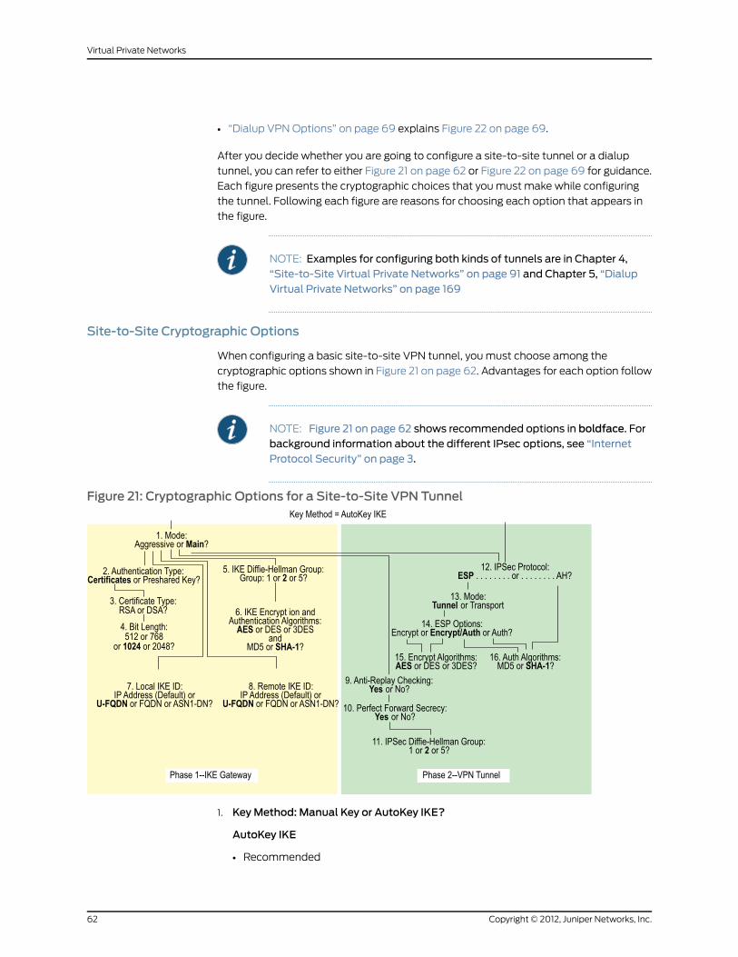
• “Dialup VPN Options” on page 69 explains Figure 22 on page 69.
After you decide whether you are going to configure a site-to-site tunnel or a dialup
tunnel, you can refer to either Figure 21 on page 62 or Figure 22 on page 69 for guidance.
Each figure presents the cryptographic choices that you must make while configuring
the tunnel. Following each figure are reasons for choosing each option that appears in
the figure.
NOTE: Examples for configuring both kinds of tunnels are in Chapter 4,“Site-to-Site Virtual Private Networks” on page 91 and Chapter 5, “DialupVirtual Private Networks” on page 169
Site-to-Site Cryptographic Options
When configuring a basic site-to-site VPN tunnel, you must choose among the
cryptographic options shown in Figure 21 on page 62. Advantages for each option follow
the figure.
NOTE: Figure 21 on page 62 shows recommended options in boldface. Forbackground information about the different IPsec options, see “InternetProtocol Security” on page 3.
Figure 21: Cryptographic Options for a Site-to-Site VPN Tunnel
1. KeyMethod: Manual Key or AutoKey IKE?
AutoKey IKE
• Recommended
Copyright © 2012, Juniper Networks, Inc.62
Virtual Private Networks

• Provides automatic key renewal and key freshness, thereby increasing security
Manual Key
• Useful for debugging IKE problems
• Eliminates IKE negotiation delays when establishing a tunnel
2. Mode: Aggressive or Main?
Aggressive
Required when the IP address of one of the IPsec peers is dynamically assigned and
a preshared key is used
Main
• Recommended
• Provides identity protection
• Can be used when the dialup user has a static IP address or if certificates are used
for authentication
3. Authentication Type: Preshared Key or Certificates?
Certificates
• Recommended
• Greater security than provided by preshared keys because you can validate
certificates with a certificate authority (CA) (For more information, see “Public Key
Cryptography” on page 35.)
Preshared Key
Easier to use and faster to set up because it does not require a Public Key Infrastructure
(PKI)
4. Certificate Type: RSA or DSA?
This depends on the CA from whom you get your certificates. There is no advantage
of one certificate type over the other.
5. Bit Length: 512 or 768 or 1024 or 2048?
512
Incurs the least processing overhead
768
• Provides more security than 512 bits
• Incurs less processing overhead than 1024 and 2048 bits
1024
• Recommended
• Provides more security than 512 and 768 bits
63Copyright © 2012, Juniper Networks, Inc.
Chapter 3: Virtual Private Network Guidelines

• Incurs less processing overhead than 2048 bits
2048
Provides the most security
6. IKE Diffie-Hellman Group: 1 or 2 or 5 or 14?
Diffie-Hellman Group 1
• Incurs less processing overhead than DH groups 2, 5 and 14
• Processing acceleration provided in Juniper Networks security hardware
Diffie-Hellman Group 2
• Recommended
• Incurs less processing overhead than DH groups 5 and 14
• Provides more security than DH group 1
• Processing acceleration provided in Juniper Networks security hardware
Diffie-Hellman Group 5
• Provides more security that DH groups 1 and 2
• Incurs less processing overhead than DH group 14
Diffie-Hellman Group 14
• Provides the most security
7. IKE Encrypt and Auth Algorithms: AES or DES or 3DES andMD5 or SHA-1 orSHA2-256?
AES
• Recommended
• Cryptographically stronger than DES and 3DES if key lengths are all equal
• Processing acceleration provided in Juniper Networks security hardware
• Approved encryption algorithm for Federal Information Processing Standards (FIPS)
and Common Criteria EAL4 standards
DES
• Incurs less processing overhead than 3DES and AES
• Useful when the remote peer does not support AES
3DES
• Provides more cryptographic security than DES
• Processing acceleration provided in Juniper Networks security hardware
MD5
Copyright © 2012, Juniper Networks, Inc.64
Virtual Private Networks

• Incurs less processing overhead than SHA-1 and SHA2-256
SHA-1
• Recommended
• Provides more cryptographic security than MD5
• Incurs less processing overhead than SHA2-256
• The only authentication algorithm that FIPS accepts
SHA2-256
• Provides more cryptographic security than SHA-1
8. Local IKE ID: IP Address (Default) or U-FQDN or FQDN or ASN1-DN?
IP Address
• Recommended
• Can only be used if the local security device has a static IP address
• Default IKE ID when using a preshared key for authentication
• Can be used with a certificate if the IP address appears in the SubjectAltName field
U-FQDN
User-Fully Qualified Domain Name (U-FQDN—an email address): Can be used with
a preshared key or a certificate if the U-FQDN appears in the SubjectAltName field
FQDN
• Fully Qualified Domain Name (FQDN): Can be used with a preshared key or a
certificate if the FQDN appears in the SubjectAltName field
• Useful for VPN gateways that have dynamic IP addresses
• Default IKE ID when using RSA or DSA certificates for authentication
ASN1-DN
• Can be used only with certificates
• Useful if the CA does not support the SubjectAltName field in the certificates it
issues
9. Remote IKE ID: IP Address (Default) or U-FQDN or FQDN or ASN1-DN?
IP Address
• Recommended
• Does not require you to enter a remote IKE ID for a peer at a static IP address when
using preshared keys for authentication and the peer is a security device
65Copyright © 2012, Juniper Networks, Inc.
Chapter 3: Virtual Private Network Guidelines

• Can be used for a device with a static IP address
• Can be used with a preshared key or a certificate if the IP address appears in the
SubjectAltName field
U-FQDN
User-Fully Qualified Domain Name (U-FQDN—an email address): Can be used with
a preshared key or a certificate if the U-FQDN appears in the SubjectAltName field
FQDN
• Fully Qualified Domain Name (FQDN): Can be used with a preshared key or a
certificate if the FQDN appears in the SubjectAltName field
• Useful for VPN gateways that have dynamic IP addresses
• Does not require you to enter a remote IKE ID when using certificates for
authentication and the peer is a security device
ASN1-DN
• Can be used only with certificates
• Useful if the CA does not support the SubjectAltName field in the certificates it
issues
10. Anti-Replay Checking: No or Yes?
Yes
• Recommended
• Enables the recipient to check sequence numbers in packet headers to prevent
denial of service (DoS) attacks caused when a malefactor resends intercepted
IPsec packets
No
Disabling this might resolve compatibility issues with third-party peers
11. Perfect Forward Secrecy: No or Yes?
Yes
• Recommended
• Perfect Forward Secrecy (PFS): Provides increased security because the peers
perform a second DH exchange to produce the key used for IPsec
encryption/decryption
No
• Provides faster tunnel setup
• Incurs less processing during Phase 2 IPsec negotiations
12. IPsec Diffie-Hellman Group: 1 or 2 or 5 or 14?
Diffie-Hellman Group 1
Copyright © 2012, Juniper Networks, Inc.66
Virtual Private Networks

• Incurs less processing overhead than DH groups 2, 5 and 14
• Processing acceleration provided in Juniper Networks security hardware
Diffie-Hellman Group 2
• Recommended
• Incurs less processing overhead than DH groups 5 and 14
• Provides more security than DH group 1
• Processing acceleration provided in Juniper Networks security hardware
Diffie-Hellman Group 5
• Provides more security that DH groups 1 and 2
• Incurs less processing overhead than DH group 14
Diffie-Hellman Group 14
• Provides the most security
13. IPsec Protocol: ESP or AH?
ESP
• Recommended
• Encapsulating Security Payload (ESP): Can provide both confidentiality through
encryption and encapsulation of the original IP packet and integrity through
authentication
• Can provide either encryption alone or authentication alone
AH
Authentication Header (AH): Provides authentication of the entire IP packet, including
the IPsec header and outer IP header
14. Mode: Tunnel or Transport?
Tunnel
• Recommended
• Conceals the original IP header, thereby increasing privacy
Transport
Required for L2TP-over-IPsec tunnel support
15. ESPOptions: Encrypt or Encrypt/Auth or Auth?
Encrypt
• Provides faster performance and incurs less processing overhead than using
encrypt/auth
• Useful when you require confidentiality but do not require authentication
67Copyright © 2012, Juniper Networks, Inc.
Chapter 3: Virtual Private Network Guidelines

Encrypt/Auth
• Recommended
• Useful when you want confidentiality and authentication
Auth
Useful when you want authentication but do not require confidentiality. Perhaps when
the information is not secret, but it is important to establish that the information truly
comes from the person who claims to send it and that nobody tampered with the
content while in transit.
16. Encrypt Algorithms: AES or DES or 3DES?
AES
• Recommended
• Cryptographically stronger than DES and 3DES if key lengths are all equal
• Processing acceleration provided in Juniper Networks security hardware
• Approved encryption algorithm for FIPS and Common Criteria EAL4 standards
DES
• Incurs less processing overhead than 3DES and AES
• Useful when the remote peer does not support AES
3DES
• Provides more cryptographic security than DES
• Processing acceleration provided in Juniper Networks security hardware
17. Auth Algorithms: MD5 or SHA-1 or SHA2-256?
MD5
Incurs less processing overhead than SHA-1
SHA-1
• Recommended
• Provides more cryptographic security than MD5
SHA2-256
• Provides more cryptographic security than SHA-1
Using the recommended options from the previous list, a generic site-to-site VPN
configuration between two security devices with static IP addresses would consist of
the following components:
• Perfect Forward Secrecy (PFS) = yes• AutoKey IKE
• Phase 2 DH group 2• Main mode
Copyright © 2012, Juniper Networks, Inc.68
Virtual Private Networks

• Encapsulating Security Payload (ESP)• 1024-bit certificates (RSA or DSA)
• Tunnel mode• Phase 1 DH group 2
• Encryption/Authentication• Encryption = AES
• Encryption = AES• Authentication = SHA-1
• Authentication = SHA-1• IKE ID = IP address (default)
• Anti-replay protection = yes
Dialup VPNOptions
When configuring a basic dialup VPN tunnel, you must choose among the cryptographic
options shown in Figure 22 on page 69. Advantages for each option follow the figure.
NOTE: Figure 22 on page 69 shows recommended options in boldface. Forbackground information about the different IPsec options, see “InternetProtocol Security” on page 3.
Figure 22: Cryptographic Options for a Dialup VPN Tunnel
1. Mode: Aggressive or Main?
Aggressive
• Recommended
• Required when the IP address of one of the IPsec peers is dynamically assigned and
a preshared key is used
69Copyright © 2012, Juniper Networks, Inc.
Chapter 3: Virtual Private Network Guidelines

• Can be used with either certificates or preshared keys for authentication
Main
Provides identity protection
2. Authentication Type: Preshared Key or Certificates?
Certificates
• Recommended
• Greater security than provided by preshared keys because you can validate
certificates with a certificate authority (CA) (For more information, see “Public Key
Cryptography” on page 35.)
Preshared Key
Easier to use and faster to set up because it does not require a Public Key Infrastructure
(PKI)
3. Certificate Type: RSA or DSA?
This depends on the CA from whom you get your certificates. There is no advantage
of one certificate type over the other.
4. Bit Length: 512 or 768 or 1024 or 2048?
512
Incurs the least processing overhead
768
• Provides more security than 512 bits
• Incurs less processing overhead than 1024 and 2048 bits
1024
• Recommended
• Provides more security than 512 and 768 bits
• Incurs less processing overhead than 2048 bits
2048
Provides the most security
5. IKE Diffie-Hellman Group: 1 or 2 or 5 or 14?
Diffie-Hellman Group 1
• Incurs less processing overhead than DH groups 2, 5 and 14
• Processing acceleration provided in Juniper Networks security hardware
Diffie-Hellman Group 2
• Recommended
• Incurs less processing overhead than DH groups 5 and 14
Copyright © 2012, Juniper Networks, Inc.70
Virtual Private Networks

• Provides more security than DH group 1
• Processing acceleration provided in Juniper Networks security hardware
Diffie-Hellman Group 5
• Incurs less processing overhead than DH group 14
• Provides more security than DH groups 1 and 2
Diffie-Hellman Group 14
• Provides the most security
6. IKE Encrypt and Auth Algorithms: AES or DES or 3DES andMD5 or SHA-1 orSHA2-256?
AES
• Recommended
• Cryptographically stronger than DES and 3DES if key lengths are all equal
• Processing acceleration provided in Juniper Networks security hardware
• Approved encryption algorithm for FIPS and Common Criteria EAL4 standards
DES
• Incurs less processing overhead than 3DES and AES
• Useful when the remote peer does not support AES
3DES
• Provides more cryptographic security than DES
• Processing acceleration provided in Juniper Networks security hardware
MD5
• Incurs less processing overhead than SHA-1 and SHA2-256
SHA-1
• Recommended
• Provides more cryptographic security than MD5
• Incurs less processing overhead than SHA2-256
SHA2-256
• Provides more cryptographic security than SHA-1
7. Local IKE ID: IP Address (Default) or U-FQDN or FQDN or ASN1-DN?
IP Address (Default)
• Does not require you to enter an IKE ID for a device with a static IP address
71Copyright © 2012, Juniper Networks, Inc.
Chapter 3: Virtual Private Network Guidelines

• Can be used for a device with a static IP address
• Can be used with a preshared key or a certificate if the IP address appears in the
SubjectAltName field
U-FQDN
• Recommended
• User-Fully Qualified Domain Name (U-FQDN—an email address): Can be used with
a preshared key or a certificate if the U-FQDN appears in the SubjectAltName field
FQDN
• Fully Qualified Domain Name (FQDN): Can be used with a preshared key or a
certificate if the FQDN appears in the SubjectAltName field
• Useful for VPN gateways that have dynamic IP addresses
ASN1-DN
• Can be used only with certificates
• Useful if the CA does not support the SubjectAltName field in the certificates it
issues
8. Anti-Replay Checking: No or Yes?
Yes
• Recommended
• Enables the recipient to check sequence numbers in packet headers to prevent
denial of service (DoS) attacks caused when a malefactor resends intercepted
IPsec packets
No
Disabling this might resolve compatibility issues with third-party peers
9. Perfect Forward Secrecy: No or Yes?
Yes
• Recommended
• Perfect Forward Secrecy (PFS): Provides increased security because the peers
perform a second DH exchange to produce the key used for IPsec
encryption/decryption
No
• Provides faster tunnel setup
• Incurs less processing during Phase 2 IPsec negotiations
10. IPsec Diffie-Hellman Group: 1 or 2 or 5 or 14?
Diffie-Hellman Group 1
Copyright © 2012, Juniper Networks, Inc.72
Virtual Private Networks

• Incurs less processing overhead than DH groups 2, 5 and 14
• Processing acceleration provided in Juniper Networks security hardware
Diffie-Hellman Group 2
• Recommended
• Incurs less processing overhead than DH groups 5 and 14
• Provides more security than DH group 1
• Processing acceleration provided in Juniper Networks security hardware
Diffie-Hellman Group 5
• Provides more security than DH groups 1 and 2
• Incurs less processing overhead than DH group 14
Diffie-Hellman Group 14
• Provides the most security
11. IPsec Protocol: ESP or AH?
ESP
• Recommended
• Encapsulating Security Payload (ESP): Can provide both confidentiality through
encryption and encapsulation of the original IP packet and integrity through
authentication
• Can provide either encryption alone or authentication alone
AH
Authentication Header (AH): Provides authentication of the entire IP packet, including
the IPsec header and outer IP header.
12. Mode: Tunnel or Transport?
Tunnel
• Recommended
• Conceals the original IP header, thereby increasing privacy
Transport
Required for L2TP-over-IPsec tunnel support
13. ESPOptions: Encrypt or Encrypt/Auth or Auth?
Encrypt
• Provides faster performance and incurs less processing overhead than using
encrypt/auth
• Useful when you require confidentiality but do not require authentication
73Copyright © 2012, Juniper Networks, Inc.
Chapter 3: Virtual Private Network Guidelines

Encrypt/Auth
• Recommended
• Useful when you want confidentiality and authentication
Auth
Useful when you want authentication but do not require confidentiality. Perhaps when
the information is not secret, but it is important to establish that the information truly
comes from the person who claims to send it and that nobody tampered with the
content while in transit.
14. Encrypt Algorithms: AES or DES or 3DES?
AES
• Recommended
• Cryptographically stronger than DES and 3DES if key lengths are all equal
• Processing acceleration provided in Juniper Networks security hardware
• Approved encryption algorithm for FIPS and Common Criteria EAL4 standards
DES
• Incurs less processing overhead than 3DES and AES
• Useful when the remote peer does not support AES
DES
• Provides more cryptographic security than DES
• Processing acceleration provided in Juniper Networks security hardware
15. Auth Algorithms: MD5 or SHA-1 or SHA2-256?
MD5
• Incurs less processing overhead than SHA-1 and SHA2-256
SHA-1
• Recommended
• Incurs less processing overhead than SHA2-256
• Provides more cryptographic security than MD5
SHA2-256
• Provides more cryptographic security than the MD5 and SHA-1
Using the recommended options from the above list, a generic dialup VPN configuration
between two security devices with static IP addresses would consist of the following
components:
• Perfect Forward Secrecy (PFS) = yes• Aggressive mode
Copyright © 2012, Juniper Networks, Inc.74
Virtual Private Networks

• Phase 2 DH group 2• 1024-bit certificates (RSA or DSA)
• Encapsulating Security Payload (ESP)• Phase 1 DH group 2
• Tunnel mode• Encryption = AES
• Encryption/Authentication• Authentication = SHA-1
• Encryption = AES• IKE ID = U-FQDN (email address)
• Authentication = SHA-1• Anti-replay protection = yes
Cryptographic Policy
A root admin user or a read-write admin user with a cryptographic role can configure a
cryptographic policy on the security device. For information on role attributes, see Role
Attributes.
To create a cryptographic policy:
set crypto-policy
You then configure all cryptographic attributes for the policy, such as encryption and
authentication algorithms, authentication method, mode of operation, Diffie-Hellman
(DH) Group, and Phase 1 and Phase 2 security associations (SA) lifetime values.
To set the attributes for a new cryptographic policy:
set crypto-policyset encrypt-alg aes256set auth-alg sha2-256set dh group2set auth-method rsa-sigset mode aggressiveset p1-sa-lifetime upper-threshold days 1set p2-sa-lifetime upper-threshold days 1save
NOTE: Youmust use the CLI to configure a cryptographic policy.
To make all cryptographic-related configurations conform to the new cryptographic
policy, you must restart the security device.
Route-Based and Policy-Based Tunnels
The configuration of a security device for VPN support is particularly flexible. You can
create route-based and policy-based VPN tunnels. Additionally, each type of tunnel can
use Manual Key or AutoKey IKE to manage the keys used for encryption and
authentication.
With policy-based VPN tunnels, a tunnel is treated as an object (or a building block) that
together with source, destination, service, and action, comprises a policy that permits
VPN traffic. (Actually, the VPN policy action is tunnel, but the action permit is implied, if
75Copyright © 2012, Juniper Networks, Inc.
Chapter 3: Virtual Private Network Guidelines

unstated). In a policy-based VPN configuration, a policy specifically references a VPN
tunnel by name.
With route-based VPNs, the policy does not specifically reference a VPN tunnel. Instead,
the policy references a destination address. When the security device does a route lookup
to find the interface through which it must send traffic to reach that address, it finds a
route through a tunnel interface, which is bound to a specific VPN tunnel.
NOTE: Typically, a tunnel interface is bound to a single tunnel. You can alsobinda tunnel interface tomultiple tunnels. Formore information, see “MultipleTunnels per Tunnel Interface” on page 263.
Thus, with a policy-based VPN tunnel, you can consider a tunnel as an element in the
construction of a policy. With a route-based VPN tunnel, you can consider a tunnel as a
means for delivering traffic, and the policy as a method for either permitting or denying
the delivery of that traffic.
The number of policy-based VPN tunnels that you can create is limited by the number
of policies that the device supports. The number of route-based VPN tunnels that you
create is limited by the number of route entries or the number of tunnel interfaces that
the device supports—whichever number is lower.
A route-based VPN tunnel configuration is a good choice when you want to conserve
tunnel resources while setting granular restrictions on VPN traffic. Although you can
create numerous policies referencing the same VPN tunnel, each policy creates an
individual IPsec security association (SA) with the remote peer, each of which counts as
an individual VPN tunnel. With a route-based approach to VPNs, the regulation of traffic
is not coupled to the means of its delivery. You can configure dozens of policies to regulate
traffic flowing through a single VPN tunnel between two sites, and there is just one IPsec
SA at work. Also, a route-based VPN configuration allows you to create policies referencing
a destination reached through a VPN tunnel in which the action is deny, unlike a
policy-based VPN configuration, in which—as stated earlier—the action must be tunnel,
implying permit.
Another advantage that route-based VPNs offer is the exchange of dynamic routing
information through VPN tunnels. You can enable an instance of a dynamic routing
protocol, such as Border Gateway Protocol (BGP), on a tunnel interface that is bound to
a VPN tunnel. The local routing instance exchanges routing information through the
tunnel with a neighbor enabled on a tunnel interface bound to the other end.
When a tunnel does not connect large networks running dynamic routing protocols and
you do not need to conserve tunnels or define various policies to filter traffic through the
tunnel, a policy-based tunnel makes sense. Also, because there is no network beyond a
dialup VPN client, policy-based VPN tunnels can be a good choice for dialup VPN
configurations.
That said, when the dialup client supports a virtual internal IP address—which the
NetScreen-Remote does—there are also compelling reasons for using a route-based
VPN configuration. A route-based dialup VPN tunnel offers the following benefits:
Copyright © 2012, Juniper Networks, Inc.76
Virtual Private Networks

• You can bind its tunnel interface to any zone to require or not require policy enforcement.
• You can define routes to force traffic through the tunnel, unlike a policy-based VPN
configuration.
• A route-based VPN tunnel simplifies the addition of a spoke to a hub-and-spoke
configuration (see “Creating Hub-and-Spoke VPNs” on page 320).
• You can adjust the proxy ID to accept any IP address from the dialup VPN client by
configuring the remote client’s address as 255.255.255.255/32.
• You can define one or more Mapped IP (MIP) addresses on the tunnel interface.
NOTE: For an example of a route-based VPN configuration for a dialupclient, see “Route-Based Dialup VPN, Dynamic Peer” on page 175.
Packet Flow: Site-to-Site VPN
To better understand how the various components comprising the creation of an IPsec
tunnel work in relation to each other, this section looks at the processing of a packet flow
through a tunnel—both when a security device sends outbound VPN traffic and when it
receives inbound VPN traffic. The processing for a route-based VPN is presented, followed
by an addendum noting the two places in the flow that differ for a policy-based VPN.
A company based in Tokyo has just opened a branch office in Paris and needs to connect
the two sites through an IPsec tunnel. The tunnel uses AutoKey IKE, the ESP protocol,
AES for encryption, SHA-1 for authentication using a preshared key, and has anti-replay
checking enabled. The security devices protecting each site are in NAT mode, and all the
zones are in the trust-vr routing domain. The addresses are as shown in Figure 23 on
page 77.
Figure 23: Site-to-Site VPN Tunnel
10.1.1.1/24
10.1.1.5
Untrust Zone
Internet
VPN1
Trust Zone
Untrust Zone
TokyoLAN
ParisLAN
Trust Zone
TokyoOffice
ethernet1
ethernet110.2.2.1/24
Outgoing Interface: ethernet3, 1.1.1.1/24
External Router: 1.1.1.250
tunnel.1, 10.1.2.1/24
tunnel.2, 10.2.1.1/24
Outgoing Interface: ethernet3, 2.2.2.2/24
External Router: 2.2.2.250
ParisOffice
10.2.2.5
77Copyright © 2012, Juniper Networks, Inc.
Chapter 3: Virtual Private Network Guidelines

The path of a packet coming from 10.1.1.5/32 in the Tokyo LAN and going to 10.2.2.5/32
in the Paris LAN through an IPsec tunnel proceeds as described in the following
subsections.
Tokyo (Initiator)
1. The host at 10.1.1.5 sends a packet destined for 10.2.2.5 to 10.1.1.1, which is the IP address
ethernet1 and is the default gateway configured in the TCP/IP settings of host.
2. The packet arrives at ethernet1, which is bound to the Trust zone.
3. If you have enabled SCREEN options such as IP spoof detection for the Trust zone,
the security device activates the SCREEN module at this point. SCREEN checking can
produce one of the following three results:
• If a SCREEN mechanism detects anomalous behavior for which it is configured to
block the packet, the security device drops the packet and makes an entry in the
event log.
• If a SCREEN mechanism detects anomalous behavior for which it is configured to
record the event but not block the packet, the security device records the event in
the SCREEN counters list for ethernet1 and proceeds to the next step.
• If the SCREEN mechanisms detect no anomalous behavior, the security device
proceeds to the next step.
If you have not enabled any SCREEN options for the Trust zone, the security device
immediately proceeds to the next step.
4. The session module performs a session lookup, attempting to match the packet with
an existing session.
If the packet does not match an existing session, the security device performs First
Packet Processing, a procedure involving the remaining steps.
If the packet matches an existing session, the security device performs Fast Processing,
using the information available from the existing session entry to process the packet.
Fast Processing bypasses the route and policy lookups because the information
generated by the bypassed steps has already been obtained during the processing of
the first packet in the session.
5. The address-mapping module checks if a Mapped IP (MIP) configuration uses the
destination IP address 10.2.2.5. Because 10.2.2.5 is not used in a MIP configuration,
the security device proceeds to the next step. (For information about packet processing
when MIPs, VIPs, or destination address translation [NAT-dst] is involved, see Packet
Flow for NAT-DST.)
6. To determine the destination zone, the route module does a route lookup for 10.2.2.5.
(The route module uses the ingress interface to determine which virtual router to use
for the route lookup.) It finds a route entry directing traffic to 10.2.2.5 through the
tunnel.1 interface bound to a VPN tunnel named “vpn1”. The tunnel interface is in the
Untrust zone. By determining the ingress and egress interfaces, the security device
has thereby determined the source and destination zones and can now do a policy
lookup.
Copyright © 2012, Juniper Networks, Inc.78
Virtual Private Networks

7. The policy engine does a policy lookup between the Trust and Untrust zones (as
determined by the corresponding ingress and egress interfaces). The action specified
in the policy matching the source address and zone, destination address and zone,
and service is permit.
8. The IPsec module checks if an active Phase 2 security association (SA) exists with
the remote peer. The Phase 2 SA check can produce either of the following results:
• If the IPsec module discovers an active Phase 2 SA with that peer, it proceeds to
step 10.
• If the IPsec module does not discover an active Phase 2 SA with that peer, it drops
the packet and triggers the IKE module.
9. The IKE module checks if an active Phase 1 SA exists with the remote peer. The Phase
1 SA check can produce either of the following results:
• If the IKE module discovers an active Phase 1 SA with the peer, it uses this SA to
negotiate a Phase 2 SA.
• If the IKE module does not discover an active Phase 1 SA with that peer, it begins
Phase 1 negotiations in main mode, and then Phase 2 negotiations.
10. The IPsec module puts an ESP header and then an outer IP header on the packet.
Using the address specified as the outgoing interface, it puts 1.1.1.1 as the source IP
address in the outer header. Using the address specified for remote gateway, it puts
2.2.2.2 as the destination IP address in the outer header. Next, it encrypts the packet
from the payload to the next header field in the original IP header. Then, it authenticates
the packet from the ESP trailer to the ESP header.
11. The security device sends the encrypted and authenticated packet destined for 2.2.2.2
through the outgoing interface (ethernet3) to the external router at 1.1.1.250.
Paris (Recipient)
1. The packet arrives at 2.2.2.2, which is the IP address of ethernet3, an interface bound
to the Untrust zone.
2. Using the SPI, destination IP address, and IPsec protocol contained in the outer packet
header, the IPsec module attempts to locate an active Phase 2 SA with the initiating
peer along with the keys to authenticate and decrypt the packet. The Phase 2 SA
check can produce one of the following three results:
• If the IPsec module discovers an active Phase 2 SA with the peer, it proceeds to
step 4.
• If the IPsec module does not discover an active Phase 2 SA with the peer but it can
match an inactive Phase 2 SA using the source IP address but not the SPI, it drops
the packet, makes an event log entry, and sends a notification that it received a bad
SPI to the initiating peer.
• If the IPsec module does not discover an active Phase 2 SA with that peer, it drops
the packet and triggers the IKE module.
79Copyright © 2012, Juniper Networks, Inc.
Chapter 3: Virtual Private Network Guidelines

3. The IKE module checks if an active Phase 1 SA exists with the remote peer. The Phase 1
SA check can produce either of the following results:
• If the IKE module discovers an active Phase 1 SA with the peer, it uses this SA to
negotiate a Phase 2 SA.
• If the IKE module does not discover an active Phase 1 SA with that peer, it begins
Phase 1 negotiations in main mode, and then Phase 2 negotiations.
4. The IPsec module performs an anti-replay check. This check can produce one of two
results:
• If the packet fails the anti-replay check, because it detects a sequence number that
the security device has already received, the security device drops the packet.
• If the packet passes the anti-replay check, the security device proceeds to the next
step.
5. The IPsec module attempts to authenticate the packet. The authentication check
can produce one of two results:
• If the packet fails the authentication check, the security device drops the packet.
• If the packet passes the authentication check, the security device proceeds to the
next step.
6. Using the Phase 2 SA and keys, the IPsec module decrypts the packet, uncovering its
original source address (10.1.1.5) and its ultimate destination (10.2.2.5). It learns that
the packet came through vpn1, which is bound to tunnel.1. From this point forward,
the security device treats the packet as if its ingress interface is tunnel.1 instead of
ethernet3. It also adjusts the anti-replay sliding window at this point.
7. If you have enabled SCREEN options for the Untrust zone, the security device activates
the SCREEN module at this point. SCREEN checking can produce one of the following
three results:
• If a SCREEN mechanism detects anomalous behavior for which it is configured to
block the packet, the security device drops the packet and makes an entry in the
event log.
• If a SCREEN mechanism detects anomalous behavior for which it is configured to
record the event but not block the packet, the security device records the event in
the SCREEN counters list for ethernet3 and proceeds to the next step.
• If the SCREEN mechanisms detect no anomalous behavior, the security device
proceeds to the next step.
8. The session module performs a session lookup, attempting to match the packet with
an existing session. It then either performs First Packet Processing or Fast Processing.
If the packet matches an existing session, the security device performs Fast Processing,
using the information available from the existing session entry to process the packet.
Fast Processing bypasses all but the last two steps (encrypting the packet and
forwarding it) because the information generated by the bypassed steps has already
been obtained during the processing of the first packet in the session.
Copyright © 2012, Juniper Networks, Inc.80
Virtual Private Networks

9. The address-mapping module checks if a Mapped IP (MIP) or Virtual IP (VIP)
configuration uses the destination IP address 10.2.2.5. Because 10.2.2.5 is not used in
a MIP or VIP configuration, the security device proceeds to the next step.
10. The route module first uses the ingress interface to determine the virtual router to use
for the route lookup; in this case, the trust-vr. It then performs a route lookup for 10.2.2.5
in the trust-vr and discovers that it is accessed through ethernet1. By determining the
ingress interface (tunnel.1) and the egress interface (ethernet1), the security device
can thereby determine the source and destination zones. The tunnel.1 interface is
bound to the Untrust zone, and ethernet1 is bound to the Trust zone. The security
device can now do a policy lookup.
11. The policy engine checks its policy list from the Untrust zone to the Trust zone and
finds a policy that grants access.
12. The security device forwards the packet through ethernet1 to its destination at 10.2.2.5.
Addendum: Policy-Based VPN
The packet flow for a policy-based VPN configuration differs from that of a route-based
VPN configuration at two points: the route lookup and the policy lookup.
Tokyo (Initiator)
The first stages of the outbound packet flow are the same for both route-based and
policy-based VPN configurations until the route lookup and subsequent policy lookup
occur:
• Route Lookup: To determine the destination zone, the route module does a route
lookup for 10.2.2.5. Not finding an entry for that specific address, the route module
resolves it to a route through ethernet3, which is bound to the Untrust zone. By
determining the ingress and egress interfaces, the security device has thereby
determined the source and destination zones, and can now perform a policy lookup.
• Policy Lookup: The policy engine does a policy lookup between the Trust and Untrust
zones. The lookup matches the source address and zone, destination address and
zone, and service and finds a policy that references a VPN tunnel named vpn1.
The security device then forwards the packet through ethernet1 to its destination at
10.2.2.5.
Paris (Recipient)
Most stages of the inbound packet flow on the recipient’s end are the same for both
route-based and policy-based VPN configurations except that the tunnel is not bound
to a tunnel interface, but to a tunnel zone. The security device learns that the packet
came through vpn1, which is bound to the Untrust-Tun tunnel zone, whose carrier zone
is the Untrust zone. Unlike route-based VPNs, the security device considers ethernet3 to
be the ingress interface of the decrypted packet—not tunnel.1.
The flow changes after packet decryption is complete. At this point, the route and policy
lookups differ:
81Copyright © 2012, Juniper Networks, Inc.
Chapter 3: Virtual Private Network Guidelines

• Route Lookup: The route module performs a route lookup for 10.2.2.5 and discovers
that it is accessed through ethernet1, which is bound to the Trust zone. By learning that
the Untrust zone is the source zone (because vpn1 is bound to the Untrust-Tun tunnel
zone, whose carrier zone is the Untrust zone) and by determining the destination zone
based on the egress interface (ethernet1 is bound to the Trust zone), the security device
can now check for a policy from the Untrust to the Trust zones that references vpn1.
• Policy Lookup: The policy engine checks its policy list from the Untrust zone to the
Trust zone and finds a policy that references a VPN tunnel named vpn1 and that grants
access to 10.2.2.5.
The security device then forwards the packet to its destination.
Tunnel Configuration Guidelines
This section offers some guidelines for configuring VPN tunnels. When configuring an
IPsec VPN tunnel, you might want to consider the following:
• ScreenOS supports up to four proposals for Phase 1 negotiations and up to four
proposals for Phase 2 negotiations. A peer must be configured to accept at least one
Phase 1 proposal and one Phase 2 proposal proffered by the other peer. For information
about Phase 1 and Phase 2 IKE negotiations, see “Tunnel Negotiation” on page 11.
• If you want to use certificates for authentication and there is more than one local
certificate loaded on the security device, you must specify which certificate you want
each VPN tunnel configuration to use. For more information about certificates, see
“Public Key Cryptography” on page 35.
• For a basic policy-based VPN:
• Use user-defined addresses in the policy, not the pre-defined address “Any”.
• The addresses and service specified in policies configured at both ends of the VPN
must match.
• Use symmetric policies for bidirectional VPN traffic.
• The proxy ID for both peers must match, which means that the service specified in the
proxy ID for both peers is the same, and the local IP address specified for one peer is
the same as the remote IP address specified for the other peer.
NOTE: The proxy ID is a three-part tuple consisting of local IPaddress–remote IP address–service.
• For a route-based VPN configuration, the proxy ID is user-configurable.
• For a policy-based VPN configuration, the security device—by default—derives the
proxy ID from the source address, destination address, and service specified in the
policy that references that VPN tunnel in the policy list. You can also define a proxy
ID for a policy-based VPN that supersedes the derived proxy ID.
Copyright © 2012, Juniper Networks, Inc.82
Virtual Private Networks
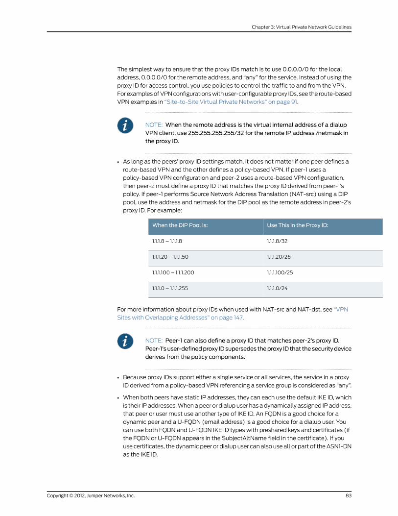
The simplest way to ensure that the proxy IDs match is to use 0.0.0.0/0 for the local
address, 0.0.0.0/0 for the remote address, and “any” for the service. Instead of using the
proxy ID for access control, you use policies to control the traffic to and from the VPN.
For examples of VPN configurations with user-configurable proxy IDs, see the route-based
VPN examples in “Site-to-Site Virtual Private Networks” on page 91.
NOTE: When the remote address is the virtual internal address of a dialupVPN client, use 255.255.255.255/32 for the remote IP address /netmask inthe proxy ID.
• As long as the peers’ proxy ID settings match, it does not matter if one peer defines a
route-based VPN and the other defines a policy-based VPN. If peer-1 uses a
policy-based VPN configuration and peer-2 uses a route-based VPN configuration,
then peer-2 must define a proxy ID that matches the proxy ID derived from peer-1’s
policy. If peer-1 performs Source Network Address Translation (NAT-src) using a DIP
pool, use the address and netmask for the DIP pool as the remote address in peer-2’s
proxy ID. For example:
Use This in the Proxy ID:When the DIP Pool Is:
1.1.1.8/321.1.1.8 – 1.1.1.8
1.1.1.20/261.1.1.20 – 1.1.1.50
1.1.1.100/251.1.1.100 – 1.1.1.200
1.1.1.0/241.1.1.0 – 1.1.1.255
For more information about proxy IDs when used with NAT-src and NAT-dst, see “VPN
Sites with Overlapping Addresses” on page 147.
NOTE: Peer-1 can also define a proxy ID that matches peer-2’s proxy ID.Peer-1’suser-definedproxy IDsupersedes theproxy ID that thesecuritydevicederives from the policy components.
• Because proxy IDs support either a single service or all services, the service in a proxy
ID derived from a policy-based VPN referencing a service group is considered as “any”.
• When both peers have static IP addresses, they can each use the default IKE ID, which
is their IP addresses. When a peer or dialup user has a dynamically assigned IP address,
that peer or user must use another type of IKE ID. An FQDN is a good choice for a
dynamic peer and a U-FQDN (email address) is a good choice for a dialup user. You
can use both FQDN and U-FQDN IKE ID types with preshared keys and certificates (if
the FQDN or U-FQDN appears in the SubjectAltName field in the certificate). If you
use certificates, the dynamic peer or dialup user can also use all or part of the ASN1-DN
as the IKE ID.
83Copyright © 2012, Juniper Networks, Inc.
Chapter 3: Virtual Private Network Guidelines
Route-Based Virtual Private Network Security Considerations
Although route changes do not affect policy-based VPNs, route-based VPNs are a
different matter. The security device can route packets through a route-based VPN tunnel
with a combination of static routes and dynamic routing protocols. As long as no route
change occurs, the security device consistently encrypts and forwards packets destined
for tunnel interfaces bound to route-based VPN tunnels.
However, when using VPN monitoring with a route-based VPN tunnel configuration, the
state of a tunnel might change from up to down. When this occurs, all route table entries
referencing the tunnel interface bound to that tunnel change to inactive. Then, when the
security device does a route lookup for traffic originally intended to be encrypted and
sent through a tunnel bound to that tunnel interface, it bypasses the route referencing
the tunnel interface and searches for a route with the next longest match. The route that
it finds might be the default route. Using this route, the security device would then send
the traffic unencrypted (that is, in clear or plain text) out through a non-tunnel interface
to the public WAN.
To avoid rerouting traffic originally intended for a VPN tunnel to the public WAN in clear
text, you can configure the security device to reroute such traffic to another tunnel, reroute
it to a leased line, or just drop it, by using one of the following work-arounds:
• “Null Route” on page 84 (drops traffic when the route to the tunnel interface becomes
inactive)
• “Dialup or Leased Line” on page 86 (reroutes traffic to an alternate secure path when
the route to the tunnel interface becomes inactive)
• “Decoy Tunnel Interface” on page 89 (drops traffic when the route to the tunnel interface
becomes inactive)
• “Virtual Router for Tunnel Interfaces” on page 89 (drops traffic when the route to the
tunnel interface becomes inactive)
• “Reroute to Another Tunnel” on page 90 (reroutes traffic to an alternate VPN tunnel
when the route to the tunnel interface becomes inactive)
Null Route
If the state of a VPN tunnel changes to “down,” the security device changes any route
referencing that tunnel interface to “ inactive.” If the route to the tunnel interface becomes
unavailable and the next choice is the default route (for example), then the security
device uses the default route to forward the traffic originally intended for the VPN tunnel.
To avoid sending traffic in plain text out to the public WAN when a route change occurs,
you can make use of a null route. A null route targets the same destination address as
the route through the tunnel interface, but it instead points the traffic to the Null interface.
The Null interface is a logical interface that drops traffic sent to it. You give the null route
a higher metric (farther from zero) than the route using the tunnel interface so that the
null route is less preferred.
Copyright © 2012, Juniper Networks, Inc.84
Virtual Private Networks

NOTE: Releases prior to ScreenOS 5.1.0 do not support a null interface.However, you can use a decoy tunnel interface to accomplish the sameobjective. For information, see “Decoy Tunnel Interface” on page 89.
For example, if you create a static route through tunnel.1 to a remote LAN with the IP
address 10.2.2.0/24, it automatically receives the default value of 1 for its metric:
set vrouter trust-vr route 10.2.2.0/24 interface tunnel.1get route…Dest-Routes for <trust-vr> (4 entries)
VsysMtrPrefPGatewayInterfaceIP-PrefixID
Root120S1.1.1.250eth30.0.0.0/03*
Root00C0.0.0.0eth31.1.1.0/242*
Root00C0.0.0.0eth110.1.1.0/241*
Root120S0.0.0.0tun.110.2.2.0/244*
In the above routing table, an asterisk ( * ) indicates that a route is active, S indicates a
static route, and “C” indicates a connected route.
In the routing table above, the security device has two routes to reach any address in the
10.2.2.0/24 subnet. The first choice is route #4 because it has the longest match with
that address. The second choice is the default route (0.0.0.0/0).
If you then add another route to 10.2.2.0/24 through the Null interface and give it a value
greater than 1, that route becomes the second routing choice to any address in the
10.2.2.0/24 subnet. If the route to 10.2.2.0/24 through tunnel.1 becomes inactive, then
the security device uses the route to the Null interface. The security device forwards
traffic for 10.2.2.0/24 to that interface, and then drops it.
set vrouter trust-vr route 10.2.2.0/24 interface null metric 10get route…Dest-Routes for <trust-vr> (5 entries)
VsysMtrPrefPGatewayInterfaceIP-PrefixID
Root120S1.1.1.250eth30.0.0.0/03*
Root00C0.0.0.0eth31.1.1.0/242*
Root00C0.0.0.0eth110.1.1.0/241*
Root120S0.0.0.0tun.110.2.2.0/244
85Copyright © 2012, Juniper Networks, Inc.
Chapter 3: Virtual Private Network Guidelines

VsysMtrPrefPGatewayInterfaceIP-PrefixID
Root1020S0.0.0.0null10.2.2.0/245*
In the routing table above, the route to 10.2.2.0/24 through tunnel.1 is inactive (indicated
by the absence of an asterisk in the far left column). Therefore, the security device
searches for the next route that has the longest match to the destination address, and
it finds route #5. (The next choice after route #5 is the default route with ID #3.) The
security device then forwards traffic for 10.2.2.0/24 to the null interface, which drops the
traffic. As a result, if the route using tunnel.1 becomes inactive, the security device drops
traffic for 10.2.2.0/24 rather than using route #3 to forward it out ethernet3 as clear text
to the router at 1.1.1.250.
Dialup or Leased Line
If you do not want to drop traffic to a remote peer when the tunnel to that peer becomes
inactive, you can add an alternate route to that peer that flows over a dialup or leased
line. This alternate route uses the same destination IP address as that in the route through
the VPN tunnel, but it has a different egress interface and a less-preferred metric. If the
route through the VPN tunnel becomes inactive, then the security device reroutes traffic
to the remote peer through the dialup or leased line.
When using a dialup or leased line as the next-choice route, there is still the possibility
that both the first- and second-choice routes can become inactive at the same time.
Then the security device resorts to the third choice, which might be the default route. In
anticipation of such a situation, you can make the dialup or leased line route the second
choice and the null route the third choice (see “Null Route” on page 84). Figure 24 on
page 86 shows how these options for handling a routing failover can work together.
Figure 24: Routing Failover Alternatives for VPN Traffic
VPN Failover to Leased Line or Null Route
In this example, you want traffic from the branch office behind Device A to reach the
corporate network behind Device B over a secure VPN connection. If the tunnel fails, you
then want traffic to flow over a leased line to the corporate office. If both the VPN tunnel
Copyright © 2012, Juniper Networks, Inc.86
Virtual Private Networks
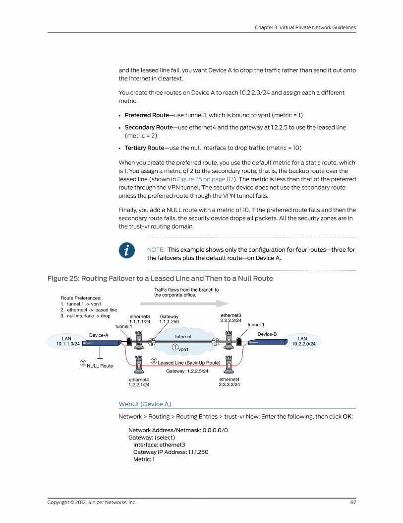
and the leased line fail, you want Device A to drop the traffic rather than send it out onto
the Internet in cleartext.
You create three routes on Device A to reach 10.2.2.0/24 and assign each a different
metric:
• Preferred Route—use tunnel.1, which is bound to vpn1 (metric = 1)
• Secondary Route—use ethernet4 and the gateway at 1.2.2.5 to use the leased line
(metric = 2)
• Tertiary Route—use the null interface to drop traffic (metric = 10)
When you create the preferred route, you use the default metric for a static route, which
is 1. You assign a metric of 2 to the secondary route; that is, the backup route over the
leased line (shown in Figure 25 on page 87). The metric is less than that of the preferred
route through the VPN tunnel. The security device does not use the secondary route
unless the preferred route through the VPN tunnel fails.
Finally, you add a NULL route with a metric of 10. If the preferred route fails and then the
secondary route fails, the security device drops all packets. All the security zones are in
the trust-vr routing domain.
NOTE: This example shows only the configuration for four routes—three forthe failovers plus the default route—on Device A.
Figure 25: Routing Failover to a Leased Line and Then to a Null Route
Route Preferences:1. tunnel.1 -> vpn12. ethernet4 -> leased line3. null interface -> drop
Traffic flows from the branch tothe corporate office.
ethernet31.1.1.1/24
Gateway1.1.1.250
ethernet32.2.2.2/24
tunnel.1 tunnel.1
LAN10.2.2.0/24
LAN10.1.1.0/24
ethernet42.3.3.2/24
ethernet41.2.2.1/24
Leased Line (Back-Up Route)
Gateway: 1.2.2.5/24
vpn1
InternetDevice-A Device-B
NULL Route
WebUI (Device A)
Network > Routing > Routing Entries > trust-vr New: Enter the following, then click OK:
Network Address/Netmask: 0.0.0.0/0Gateway: (select)Interface: ethernet3Gateway IP Address: 1.1.1.250Metric: 1
87Copyright © 2012, Juniper Networks, Inc.
Chapter 3: Virtual Private Network Guidelines

Network > Routing > Routing Entries > trust-vr New: Enter the following and then click
OK:
Network Address/Netmask: 10.2.2.0/24Gateway: (select)Interface: tunnel.1Gateway IP Address: 0.0.0.0
Metric: 1
Network > Routing > Routing Entries > trust-vr New: Enter the following and then click
OK:
Network Address/Netmask: 10.2.2.0/24Gateway: (select)Interface: ethernet4Gateway IP Address: 1.2.2.5
Metric: 2
Network > Routing > Routing Entries > trust-vr New: Enter the following and then click
OK:
Network Address/Netmask: 10.2.2.0/24Gateway: (select)Interface: NullGateway IP Address: 0.0.0.0
Metric: 10
CLI (Device A)
set vrouter trust-vr route 0.0.0.0/0 interface ethernet3 gateway 1.1.1.250set vrouter trust-vr route 10.2.2.0/24 interface tunnel.1set vrouter trust-vr route 10.2.2.0/24 interface ethernet4 gateway 1.2.2.5 metric 2set vrouter trust-vr route 10.2.2.0/24 interface null metric 10save
You can verify that the new routes are present by executing the get route command.
device-C-> get routeIPv4 Dest-Routes for <untrust-vr> (0 entries)--------------------------------------------------------------------------------H: Host C: Connected S: Static A: Auto-ExportedI: Imported R: RIP P: Permanent D: Auto-DiscoverediB: IBGP eB: EBGPO: OSPF E1: OSPF external type 1E2: OSPF external type 2
IPv4 Dest-Routes for <trust-vr> (7 entries)--------------------------------------------------------------------------------ID IP-Prefix Interface Gateway P Pref Mtr Vsys--------------------------------------------------------------------------------* 8 0.0.0.0/0 eth1/1 10.100.37.1 S 20 1 Root* 7 1.1.1.1/32 eth1/2 0.0.0.0 H 0 0 Root* 3 192.168.1.1/32 mgt 0.0.0.0 H 0 0 Root* 2 192.168.1.0/24 mgt 0.0.0.0 C 0 0 Root* 4 10.100.37.0/24 eth1/1 0.0.0.0 C 0 0 Root
Copyright © 2012, Juniper Networks, Inc.88
Virtual Private Networks

* 5 10.100.37.170/32 eth1/1 0.0.0.0 H 0 0 Root* 6 1.1.1.0/24 eth1/2 0.0.0.0 C 0 0 Root
The route table entry with ID 5 directs traffic for 10.2.2.0/24 to tunnel.1 and then through
the VPN tunnel. It is the preferred route for traffic to reach the 10.2.2.0 network. If that
tunnel fails, the next best route is route entry 6 over a leased line through a gateway at
1.2.2.5. If the connection for route entry 6 fails, route entry 7 becomes the next best route,
and the security device directs traffic for 10.2.2.0/24 to the null interface, which then
drops it.
Decoy Tunnel Interface
Instead of failing over traffic from a VPN tunnel to a null interface (and then dropping
it), you can use a nonfunctioning tunnel interface to accomplish the same objective.
NOTE: Releases prior to ScreenOS 5.1.0 do not support a null interface (see“Null Route” on page 84). However, you can use a decoy tunnel interface toaccomplish the same objective.
To set up a decoy tunnel interface, do the following:
1. Create a second tunnel interface, but do not bind it to a VPN tunnel. Instead, bind it
to a tunnel zone that is in the same virtual routing domain as the first tunnel interface.
NOTE: If a tunnel interface is bound to a tunnel zone, its status is alwaysup.
2. Define a second route to the same destination using this second tunnel interface, and
assign it a higher metric (farther from zero) than the preferred route.
If the state of the functioning tunnel interface changes from up to down and the route
table entry referencing that interface becomes inactive, all subsequent route lookups
find this second route to the nonfunctioning tunnel interface. The security device
forwards traffic to the second tunnel interface and because it is not bound to a VPN
tunnel, the device drops the traffic.
Virtual Router for Tunnel Interfaces
To avoid the case where the route through a VPN tunnel becomes deactivated and then
fails over traffic originally intended to pass through the tunnel to the default route, you
can create a special virtual routing domain exclusively for VPN traffic. To set this up, take
the following steps:
1. Create a separate virtual router to use for all routes pointing to tunnel interfaces and
name it, for example, “VR-VPN.”
2. Create a security zone—named, for example, “VPN zone” —and bind it to VR-VPN.
89Copyright © 2012, Juniper Networks, Inc.
Chapter 3: Virtual Private Network Guidelines

3. Bind all tunnel interfaces to the VPN zone, and also put all addresses for remote sites
that you want to reach through VPN tunnels in this zone.
4. Configure static routes in all other virtual routers to VR-VPN for traffic that you want
encrypted and sent through the tunnels. If necessary, define static routes for decrypted
traffic from VR-VPN to the other virtual routers. Such routes are necessary to allow
inbound VPN traffic through the tunnel if it is initiated from the remote site.
If the state of a tunnel interface changes from up to down, the security device still
forwards traffic to VR-VPN, where—because the state of the route to that interface
is now inactive and there are no other matching routes—the security device drops the
traffic.
Reroute to Another Tunnel
You can configure two or more VPN tunnels to the same remote peer. If one tunnel goes
down, the security device can then reroute traffic through another VPN tunnel. For
information and examples about configuring redundant VPN tunnels, see the following:
• Active-to-Backup Tunnel Failover
• Configuring Dual Active Tunnels
• Configuring Tunnel Failover Weights
Copyright © 2012, Juniper Networks, Inc.90
Virtual Private Networks

CHAPTER 4
Site-to-Site Virtual Private Networks
This chapter explains how to configure a site-to-site virtual private network (VPN) tunnel
between two Juniper Networks security devices. It examines route-based and policy-based
VPN tunnels, presents the various elements that you must consider when setting up a
tunnel, and offers several examples.
This chapter contains the following sections:
• Site-to-Site VPN Configurations on page 91
• Dynamic IKE Gateways Using FQDN on page 137
• VPN Sites with Overlapping Addresses on page 147
• Transparent Mode VPN on page 158
• Transport mode IPsec VPN on page 165
Site-to-Site VPN Configurations
An IPsec VPN tunnel exists between two gateways, and each gateway needs an IP
address. When both gateways have static IP addresses, you can configure the following
kinds of tunnels:
• Site-to-Site VPN, AutoKey IKE tunnel (with a preshared key or certificates)
• Site-to-Site VPN, Manual Key tunnel
When one gateway has a static address and the other has a dynamically assigned address,
you can configure the following kind of tunnel:
• Dynamic Peer Site-to-Site VPN, AutoKey IKE tunnel (with a preshared key or
certificates)
As used here, a static site-to-site VPN involves an IPsec tunnel connecting two sites,
each with a security device operating as a secure gateway. The physical interface or
subinterface used as the outgoing interface on both devices has a fixed IP address, and
the internal hosts also have static IP addresses. If the security device is in transparent
mode, it uses the VLAN1 address as the IP address for the outgoing interface. With a
static site-to-site VPN, hosts at either end of the tunnel can initiate the VPN tunnel setup
because the IP address of the remote gateway remains constant and thus reachable.
91Copyright © 2012, Juniper Networks, Inc.

If the outgoing interface of one of the security devices has a dynamically assigned IP
address, that device is termed a dynamic peer and the VPN is configured differently. With
a dynamic peer site-to-site VPN, only hosts behind the dynamic peer can initiate the VPN
tunnel setup because only their remote gateway has a fixed IP address and is thus
reachable from their local gateway. However, after a tunnel is established between a
dynamic peer and a static peer, hosts behind either gateway can initiate VPN traffic if
the destination hosts have fixed IP addresses.
NOTE: For background information about the available VPN options, see“Internet Protocol Security” on page 3. For guidance when choosing amongthe various options, see “Virtual Private Network Guidelines” on page 61.
The configuration of a site-to-site VPN tunnel requires the coordination of the tunnel
configuration with that of other settings—interfaces, addresses, routes, and policies. The
three example VPN configurations in this section are set in the following context: an
office in Tokyo wants to communicate securely with an office in Paris through an IPsec
VPN tunnel.
Figure 26: Site-to-Site VPN Tunnel Configuration
Untrust Zone
Internet
Tunnel:vpn1
Trust Zone
Untrust Zone
LAN10.1.1.0/24
LAN10.2.2.0/24
Trust Zone
TokyoOffice
ethernet110.1.1.1/24
NAT
ethernet110.2.2.1/24
ethernet3, 1.1.1.1/24
external router, 1.1.1.250
tunnel.1, Unnumbered
tunnel.1, Unnumbered
ethernet3, 2.2.2.2/24
external router, 2.2.2.250
ParisOffice
TokyoSecurity Device
ParisSecurity Device
The administrators in both offices configure the following settings:
• Interfaces – Security Zones and Tunnel
• Addresses
• VPN (one of the following)
• AutoKey IKE
• Dynamic Peer
• Manual Key
Copyright © 2012, Juniper Networks, Inc.92
Virtual Private Networks
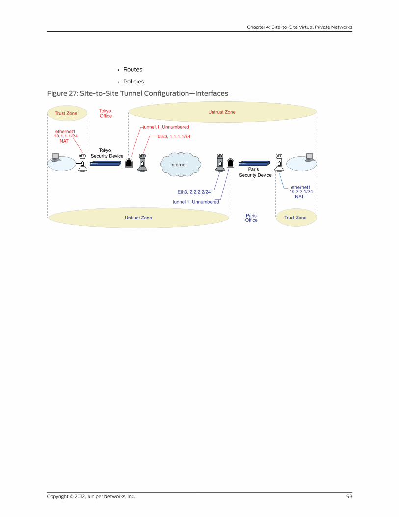
• Routes
• Policies
Figure 27: Site-to-Site Tunnel Configuration—Interfaces
Untrust Zone
Internet
Trust Zone
Untrust Zone Trust Zone
TokyoOffice
ethernet110.1.1.1/24
NAT
ethernet110.2.2.1/24
NAT
Eth3, 1.1.1.1/24
tunnel.1, Unnumbered
tunnel.1, Unnumbered
Eth3, 2.2.2.2/24
ParisOffice
TokyoSecurity Device
ParisSecurity Device
93Copyright © 2012, Juniper Networks, Inc.
Chapter 4: Site-to-Site Virtual Private Networks

1. Interfaces – Security Zones and Tunnel
The admin at the Tokyo office configures the security zone and tunnel interfaces with
the settings that appear in the upper half of Figure 27 on page 93. The admin at the
Paris office does likewise with the settings that appear in the lower half of the figure.
Ethernet3 is going to be the outgoing interface for VPN traffic and the remote gateway
for VPN traffic sent from the other end of the tunnel.
Ethernet1 is in NAT mode so each admin can assign IP addresses to all the internal
hosts, yet when traffic passes from the Trust zone to the Untrust zone, the security
device translates the source IP address in the packet headers to the address of the
Untrust zone interface, ethernet3—1.1.1.1 for Tokyo, and 2.2.2.2 for Paris.
For a route-based VPN, each admin binds the tunnel interface tunnel.1 to the VPN
tunnel vpn1. By defining a route to the address space of the remote office LAN, the
security device can direct all traffic bound for that LAN to the tunnel.1 interface and
thus through the tunnel to which tunnel.1 is bound.
Because policy-based NAT services are not needed, a route-based VPN configuration
does not require tunnel.1 to have an IP address/netmask, and a policy-based VPN
configuration does not even require a tunnel interface.
Figure 28: Site-to-Site Tunnel Configuration—Addresses
2. Addresses
The admins define addresses for later use in inbound and outbound policies. The
admin at the Tokyo office defines the addresses that appear in the upper half of Figure
28 on page 94. The admin at the Paris office does likewise with the addresses that
appear in the lower half of the figure.
For policy-based VPNs, the security device derives proxy IDs from policies. Because
the proxy IDs used by the security devices at both ends of the VPN tunnel must match
perfectly, you cannot use the predefined address “ANY,” whose IP address is 0.0.0.0/0,
at one end of the tunnel if you use a more specific address at the other end. For
example:
If the proxy ID in Tokyo is as follows:
From: 0.0.0.0/0To: 10.2.2.0/24Service: ANY
Copyright © 2012, Juniper Networks, Inc.94
Virtual Private Networks

And if the proxy ID in Paris is as follows:
To: 10.1.1.0/24From: 10.2.2.0/24Service: ANY
Then the proxy IDs do not match, and IKE negotiations will fail.
NOTE: Beginning with ScreenOS 5.0.0, you can also define proxy IDs forVPN tunnels referenced in policy-based VPN configurations.
For route-based VPNs, you can use “0.0.0.0/0–0.0.0.0/0–any” to define the local
and remote IP addresses and service type for a proxy ID. You can then use more
restrictive policies to filter the inbound and outbound VPN traffic by source address,
destination address, and service type.
Figure 29: Site-to-Site Tunnel Configuration—VPN Tunnel
3. VPN
You can configure one of the following three VPNs:
• AutoKey IKE
The AutoKey IKE method uses a preshared key or a certificate to refresh—that is,
change—the encryption and authentication keys automatically at user-defined
intervals (known as key lifetimes). Essentially, frequently updating these keys
strengthens security, although excessively short lifetimes might reduce overall
performance.
• Dynamic Peer
A dynamic peer is a remote gateway that has a dynamically assigned IP address.
Because the IP address of the remote peer might be different each time IKE
negotiations begin, hosts behind the peer must initiate VPN traffic. Also—if using a
preshared key for authentication—the peer must send an IKE ID during the first
message of Phase 1 negotiations in aggressive mode to identify itself.
• Manual Key
95Copyright © 2012, Juniper Networks, Inc.
Chapter 4: Site-to-Site Virtual Private Networks
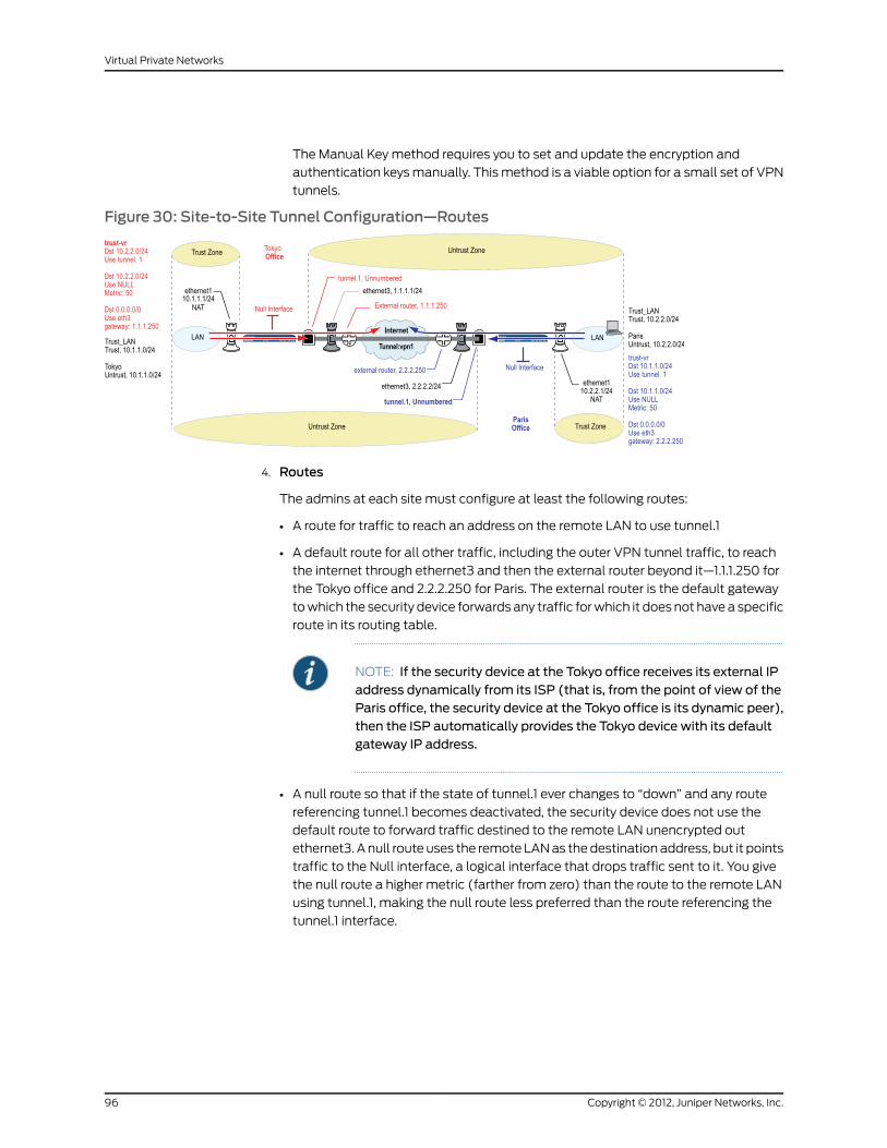
The Manual Key method requires you to set and update the encryption and
authentication keys manually. This method is a viable option for a small set of VPN
tunnels.
Figure 30: Site-to-Site Tunnel Configuration—Routes
4. Routes
The admins at each site must configure at least the following routes:
• A route for traffic to reach an address on the remote LAN to use tunnel.1
• A default route for all other traffic, including the outer VPN tunnel traffic, to reach
the internet through ethernet3 and then the external router beyond it—1.1.1.250 for
the Tokyo office and 2.2.2.250 for Paris. The external router is the default gateway
to which the security device forwards any traffic for which it does not have a specific
route in its routing table.
NOTE: If the security device at the Tokyo office receives its external IPaddress dynamically from its ISP (that is, from the point of view of theParis office, the security device at the Tokyo office is its dynamic peer),then the ISP automatically provides the Tokyo device with its defaultgateway IP address.
• A null route so that if the state of tunnel.1 ever changes to “down” and any route
referencing tunnel.1 becomes deactivated, the security device does not use the
default route to forward traffic destined to the remote LAN unencrypted out
ethernet3. A null route uses the remote LAN as the destination address, but it points
traffic to the Null interface, a logical interface that drops traffic sent to it. You give
the null route a higher metric (farther from zero) than the route to the remote LAN
using tunnel.1, making the null route less preferred than the route referencing the
tunnel.1 interface.
Copyright © 2012, Juniper Networks, Inc.96
Virtual Private Networks

Figure 31: Site-to-Site Tunnel Configuration—Policies
5. Policies
The admins at each site define policies to permit traffic between the two offices:
• A policy permitting any kind of traffic from “Trust_LAN” in the Trust zone to “Paris”
or “Tokyo” in the Untrust zone
• A policy permitting any kind of traffic from “Paris” or “Tokyo” in the Untrust zone to
“Trust_LAN” in the Trust zone
Because the preferred route to the remote site specifies tunnel.1, which is bound to
the VPN tunnel vpn1, the policy does not need to reference the VPN tunnel.
Route-Based Site-to-Site VPN, AutoKey IKE
In this example, an AutoKey IKE tunnel using either a preshared secret or a pair of
certificates (one at each end of the tunnel) provides the secure connection between the
Tokyo and Paris offices. For the Phase 1 and Phase 2 security levels, you specify one
Phase 1 proposal—either pre-g2-3des-sha for the preshared key method or
rsa-g2-3des-sha for certificates—and select the predefined “Compatible” set of proposals
for Phase 2. All zones are in the trust-vr.
97Copyright © 2012, Juniper Networks, Inc.
Chapter 4: Site-to-Site Virtual Private Networks
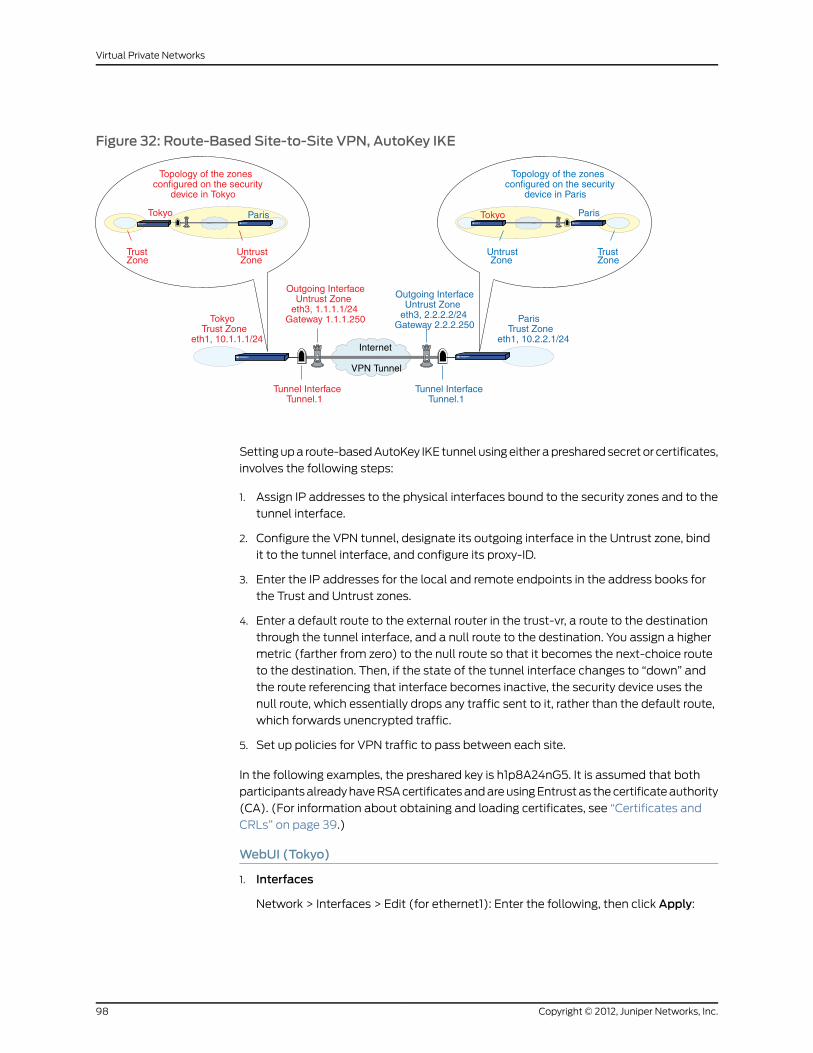
Figure 32: Route-Based Site-to-Site VPN, AutoKey IKE
Paris
Topology of the zonesconfigured on the security
device in Tokyo
TrustZone
UntrustZone
Tokyo
Topology of the zonesconfigured on the security
device in Paris
TrustZone
Tunnel InterfaceTunnel.1
Tunnel InterfaceTunnel.1
UntrustZone
Tokyo Paris
Outgoing InterfaceUntrust Zone
eth3, 1.1.1.1/24Gateway 1.1.1.250
Outgoing InterfaceUntrust Zone
eth3, 2.2.2.2/24Gateway 2.2.2.250
TokyoTrust Zone
eth1, 10.1.1.1/24
ParisTrust Zone
eth1, 10.2.2.1/24
VPN Tunnel
Internet
Setting up a route-based AutoKey IKE tunnel using either a preshared secret or certificates,
involves the following steps:
1. Assign IP addresses to the physical interfaces bound to the security zones and to the
tunnel interface.
2. Configure the VPN tunnel, designate its outgoing interface in the Untrust zone, bind
it to the tunnel interface, and configure its proxy-ID.
3. Enter the IP addresses for the local and remote endpoints in the address books for
the Trust and Untrust zones.
4. Enter a default route to the external router in the trust-vr, a route to the destination
through the tunnel interface, and a null route to the destination. You assign a higher
metric (farther from zero) to the null route so that it becomes the next-choice route
to the destination. Then, if the state of the tunnel interface changes to “down” and
the route referencing that interface becomes inactive, the security device uses the
null route, which essentially drops any traffic sent to it, rather than the default route,
which forwards unencrypted traffic.
5. Set up policies for VPN traffic to pass between each site.
In the following examples, the preshared key is h1p8A24nG5. It is assumed that both
participants already have RSA certificates and are using Entrust as the certificate authority
(CA). (For information about obtaining and loading certificates, see “Certificates and
CRLs” on page 39.)
WebUI (Tokyo)
1. Interfaces
Network > Interfaces > Edit (for ethernet1): Enter the following, then click Apply:
Copyright © 2012, Juniper Networks, Inc.98
Virtual Private Networks

Zone Name: TrustStatic IP: (select this option when present)IP Address/Netmask: 10.1.1.1/24
Select the following, then click OK:
Interface Mode: NAT
Network > Interfaces > Edit (for ethernet3): Enter the following, then click OK:
Zone Name: UntrustStatic IP: (select this option when present)IP Address/Netmask: 1.1.1.1/24
Network > Interfaces > New Tunnel IF: Enter the following, then click OK:
Tunnel Interface Name: tunnel.1Zone (VR): Untrust (trust-vr)Unnumbered: (select)Interface: ethernet3 (trust-vr)
2. Addresses
Policy > Policy Elements> Addresses > List > New: Enter the following, then click OK:
Address Name: Trust_LANIP Address/Domain Name:IP/Netmask: (select), 10.1.1.0/24
Zone: Trust
Policy > Policy Elements> > Addresses > List > New: Enter the following, then click
OK:
Address Name: Paris_OfficeIP Address/Domain Name:IP/Netmask: (select), 10.2.2.0/24
Zone: Untrust
3. VPN
VPNs > AutoKey Advanced > Gateway > New: Enter the following, then click OK:
Gateway Name: To_ParisSecurity Level: CustomRemote Gateway Type:Static IP Address: (select), IP Address/Hostname: 2.2.2.2
Preshared Key
Preshared Key: h1p8A24nG5Outgoing Interface: ethernet3
> Advanced: Enter the following advanced settings, then click Return to return to the
basic Gateway configuration page:
Security Level: CustomPhase 1 Proposal (for Custom Security Level): pre-g2-3des-shaMode (Initiator): Main (ID Protection)
(or)
Certificates
99Copyright © 2012, Juniper Networks, Inc.
Chapter 4: Site-to-Site Virtual Private Networks

Outgoing Interface: ethernet3
> Advanced: Enter the following advanced settings, then click Return to return to the
basic Gateway configuration page:
Security Level: CustomPhase 1 Proposal (for Custom Security Level): rsa-g2-3des-shaPreferred certificate (optional)Peer CA: EntrustPeer Type: X509-SIG
VPNs > AutoKey IKE > New: Enter the following, then click OK:
VPNName: Tokyo_ParisSecurity Level: CompatibleRemote Gateway:Predefined: (select), To_Paris
> Advanced: Enter the following advanced settings, then click Return to return to the
basic AutoKey IKE configuration page:
Security Level: CompatibleBind to: Tunnel Interface, tunnel.1Proxy-ID: (select)Local IP / Netmask: 10.1.1.0/24Remote IP / Netmask: 10.2.2.0/24Service: ANY
4. Routes
Network > Routing > Routing Entries > trust-vr New: Enter the following, then click
OK:
Network Address/Netmask: 0.0.0.0/0Gateway: (select)Interface: ethernet3Gateway IP Address: 1.1.1.250
Network > Routing > Routing Entries > trust-vr New: Enter the following, then click
OK:
Network Address/Netmask: 10.2.2.0/24Gateway: (select)Interface: Tunnel.1Gateway IP Address: 0.0.0.0
Network > Routing > Routing Entries > trust-vr New: Enter the following, then click
OK:
Network Address/Netmask: 10.2.2.0/24Gateway: (select)Interface: NullGateway IP Address: 0.0.0.0Metric: 10
5. Policies
Policies > (From: Trust, To: Untrust) New: Enter the following, then click OK:
Name: To ParisSource Address: Trust_LAN
Copyright © 2012, Juniper Networks, Inc.100
Virtual Private Networks

Destination Address: Paris_OfficeService: ANYAction: PermitPosition at Top: (select)
Policies > (From: Untrust, To: Trust) > New: Enter the following, then click OK:
Name: From ParisSource Address: Paris_OfficeDestination Address: Trust_LANService: ANYAction: PermitPosition at Top: (select)
WebUI (Paris)
1. Interfaces
Network > Interfaces > Edit (for ethernet1): Enter the following, then click Apply:
Zone Name: TrustStatic IP: (select this option when present)IP Address/Netmask: 10.2.2.1/24
Select the following, then click OK:
Interface Mode: NAT
Network > Interfaces > Edit (for ethernet3): Enter the following, then click OK:
Zone Name: UntrustStatic IP: (select this option when present)IP Address/Netmask: 2.2.2.2/24
Network > Interfaces > New Tunnel IF: Enter the following, then click OK:
Tunnel Interface Name: tunnel.1Zone (VR): Untrust (trust-vr)Unnumbered: (select)Interface: ethernet3 (trust-vr)
2. Addresses
Policy > Policy Elements> > Addresses > List > New: Enter the following, then click
OK:
Address Name: Trust_LANIP Address/Domain Name:IP/Netmask: (select), 10.2.2.0/24
Zone: Trust
Policy > Policy Elements> > Addresses > List > New: Enter the following, then click
OK:
Address Name: Tokyo_OfficeIP Address/Domain Name:IP/Netmask: (select), 10.1.1.0/24
Zone: Untrust
3. VPN
101Copyright © 2012, Juniper Networks, Inc.
Chapter 4: Site-to-Site Virtual Private Networks

VPNs > AutoKey Advanced > Gateway > New: Enter the following, then click OK:
Gateway Name: To_TokyoSecurity Level: CustomRemote Gateway Type:Static IP Address: (select), IP Address/Hostname: 1.1.1.1
Preshared Key
Preshared Key: h1p8A24nG5Outgoing Interface: ethernet3
> Advanced: Enter the following advanced settings, then click Return to return to the
basic Gateway configuration page:
Security Level: CustomPhase 1 Proposal (For Custom Security Level): pre-g2-3des-shaMode (Initiator): Main (ID Protection)
(or)
Certificates
Outgoing Interface: ethernet3
Security Level: CustomPhase 1 Proposal (for Custom Security Level): rsa-g2-3des-shaPreferred certificate (optional)Peer CA: EntrustPeer Type: X509-SIG
VPNs > AutoKey IKE > New: Enter the following, then click OK:
Name: Paris_TokyoSecurity Level: CompatibleRemote Gateway:Predefined: (select), To_Tokyo
> Advanced: Enter the following advanced settings, then click Return to return to the
basic Gateway configuration page:
Security Level: CompatibleBind to: Tunnel Interface, tunnel.1Proxy-ID: (select)Local IP / Netmask: 10.2.2.0/24Remote IP / Netmask: 10.1.1.0/24Service: ANY
4. Routes
Network > Routing > Routing Entries > trust-vr New: Enter the following, then click
OK:
Network Address/Netmask: 0.0.0.0/0Gateway: (select)Interface: ethernet3Gateway IP Address: 2.2.2.250
Network > Routing > Routing Entries > trust-vr New: Enter the following, then click
OK:
Copyright © 2012, Juniper Networks, Inc.102
Virtual Private Networks

Network Address/Netmask: 10.1.1.0/24Gateway: (select)Interface: Tunnel.1Gateway IP Address: 0.0.0.0
Network > Routing > Routing Entries > trust-vr New: Enter the following, then click
OK:
Network Address/Netmask: 10.1.1.0/24Gateway: (select)Interface: NullGateway IP Address: 0.0.0.0Metric: 10
5. Policies
Policies > (From: Trust, To: Untrust) New: Enter the following, then click OK:
Name: To_TokyoSource Address:Address Book Entry: (select), Trust_LAN
Destination Address:Address Book Entry: (select), Tokyo_Office
Service: ANYAction: PermitPosition at Top: (select)
Policies > (From: Untrust, To: Trust) New: Enter the following, then click OK:
Name: From_TokyoSource Address:Address Book Entry: (select), Tokyo_Office
Destination Address:Address Book Entry: (select), Trust_LAN
Service: ANYAction: PermitPosition at Top: (select)
CLI (Tokyo)
1. Interfaces
set interface ethernet1 zone trustset interface ethernet1 ip 10.1.1.1/24set interface ethernet1 natset interface ethernet3 zone untrustset interface ethernet3 ip 1.1.1.1/24set interface tunnel.1 zone untrustset interface tunnel.1 ip unnumbered interface ethernet3
2. Addresses
set address trust Trust_LAN 10.1.1.0/24set address untrust Paris_Office 10.2.2.0/24
3. VPN
Preshared Key
103Copyright © 2012, Juniper Networks, Inc.
Chapter 4: Site-to-Site Virtual Private Networks

set ike gateway To_Paris address 2.2.2.2 main outgoing-interface ethernet3 preshareh1p8A24nG5 proposal pre-g2-3des-shaset vpn Tokyo_Paris gateway To_Paris sec-level compatibleset vpn Tokyo_Paris bind interface tunnel.1set vpn Tokyo_Paris proxy-id local-ip 10.1.1.0/24 remote-ip 10.2.2.0/24 any
(or)
set ike gateway To_Paris address 2.2.2.2 main outgoing-interface ethernet3 proposalrsa-g2-3des-shaset ike gateway To_Paris cert peer-ca 1set ike gateway To_Paris cert peer-cert-type x509-sigset vpn Tokyo_Paris gateway To_Paris sec-level compatibleset vpn Tokyo_Paris bind interface tunnel.1set vpn Tokyo_Paris proxy-id local-ip 10.1.1.0/24 remote-ip 10.2.2.0/24 any
NOTE: The number 1 is the CA ID number. To discover the CA’s ID number,use the following command: get ike ca.
4. Routes
set vrouter trust-vr route 0.0.0.0/0 interface ethernet3 gateway 1.1.1.250set vrouter trust-vr route 10.2.2.0/24 interface tunnel.1set vrouter trust-vr route 10.2.2.0/24 interface null metric 10
5. Policies
set policy topname “ToParis” fromtrust to untrust Trust_LANParis_Office anypermitset policy top name “From Paris” from untrust to trust Paris_Office Trust_LAN anypermitsave
CLI (Paris)
1. Interfaces
set interface ethernet1 zone trustset interface ethernet1 ip 10.2.2.1/24set interface ethernet1 natset interface ethernet3 zone untrustset interface ethernet3 ip 2.2.2.2/24set interface tunnel.1 zone untrustset interface tunnel.1 ip unnumbered interface ethernet3
2. Addresses
set address trust Trust_LAN 10.2.2.0/24set address untrust Tokyo_Office 10.1.1.0/24
3. VPN
Preshared Key
set ike gateway To_Tokyo address 1.1.1.1 main outgoing-interface ethernet3 preshareh1p8A24nG5 proposal pre-g2-3des-shaset vpn Paris_Tokyo gateway To_Tokyo sec-level compatibleset vpn Paris_Tokyo bind interface tunnel.1set vpn Paris_Tokyo proxy-id local-ip 10.2.2.0/24 remote-ip 10.1.1.0/24 any
Copyright © 2012, Juniper Networks, Inc.104
Virtual Private Networks

(or)
Certificate
set ike gateway To_Tokyo address 1.1.1.1 main outgoing-interface ethernet3 proposalrsa-g2-3des-shaset ike gateway To_Tokyo cert peer-ca 1set ike gateway To_Tokyo cert peer-cert-type x509-sigset vpn Paris_Tokyo gateway To_Tokyo sec-level compatibleset vpn Paris_Tokyo bind interface tunnel.1set vpn Paris_Tokyo proxy-id local-ip 10.2.2.0/24 remote-ip 10.1.1.0/24 any
4. Routes
set vrouter trust-vr route 0.0.0.0/0 interface ethernet3 gateway 2.2.2.250set vrouter trust-vr route 10.1.1.0/24 interface tunnel.1set vrouter trust-vr route 10.1.1.0/24 interface null metric 10
5. Policies
set policy top name “To Tokyo” from trust to untrust Trust_LAN Tokyo_Office anypermitset policy top name “From Tokyo” from untrust to trust Tokyo_Office Trust_LAN anypermitsave
Policy-Based Site-to-Site VPN, AutoKey IKE
In this example, an AutoKey IKE tunnel using either a preshared secret or a pair of
certificates (one at each end of the tunnel) provides the secure connection between the
Tokyo and Paris offices. For the Phase 1 and Phase 2 security levels, you specify one
Phase 1 proposal—either pre-g2-3des-sha for the preshared key method or
rsa-g2-3des-sha for certificates—and select the predefined “Compatible” set of proposals
for Phase 2. All zones are in the trust-vr.
Figure 33: Policy-Based Site-to-Site VPN, AutoKey IKE
Topology of the zonesconfigured on the security
device in Tokyo
TrustZone
Untrust-TunZone
UntrustZone
Tokyo
Topology of the zonesconfigured on the security
device in Paris
TrustZone
Untrust-TunZone
UntrustZone
Tokyo ParisParis
Outgoing InterfaceUntrust Zone
eth3, 1.1.1.1/24Gateway 1.1.1.250
Outgoing InterfaceUntrust Zone
eth3, 2.2.2.2/24Gateway 2.2.2.250Tokyo
Trust Zoneeth1, 10.1.1.1/24
ParisTrust Zone
eth1, 10.2.2.1/24
VPN Tunnel
Internet
Setting up the AutoKey IKE tunnel using AutoKey IKE, with either a preshared secret or
certificates, involves the following steps:
105Copyright © 2012, Juniper Networks, Inc.
Chapter 4: Site-to-Site Virtual Private Networks

1. Define security zone interface IP addresses.
2. Make address book entries for the local and remote end entities.
3. Define the remote gateway and key exchange mode, and specify either a preshared
secret or a certificate.
4. Create the Autokey IKE VPN.
5. Set a default route to the external router.
6. Configure policies.
In the following examples, the preshared key is h1p8A24nG5. It is assumed that both
participants already have RSA certificates and are using Entrust as the certificate authority
(CA). (For information about obtaining and loading certificates, see “Certificates and
CRLs” on page 39.)
WebUI (Tokyo)
1. Interfaces
Network > Interfaces > Edit (for ethernet1): Enter the following, then click Apply:
Zone Name: TrustStatic IP: (select this option when present)IP Address/Netmask: 10.1.1.1/24
Select the following, then click OK:
Interface Mode: NAT
Network > Interfaces > Edit (for ethernet3): Enter the following, then click OK:
Zone Name: UntrustStatic IP: (select this option when present)IP Address/Netmask: 1.1.1.1/24
2. Addresses
Policy > Policy Elements > Addresses > List > New: Enter the following, then clickOK:
Address Name: Trust_LANIP Address/Domain Name:IP/Netmask: (select), 10.1.1.0/24
Zone: Trust
Policy > Policy Elements > Addresses > List > New: Enter the following, then clickOK:
Address Name: Paris_OfficeIP Address/Domain Name:IP/Netmask: (select), 10.2.2.0/24
Zone: Untrust
3. VPN
VPNs > AutoKey Advanced > Gateway > New: Enter the following, then click OK:
Gateway Name: To_ParisSecurity Level: Custom
Copyright © 2012, Juniper Networks, Inc.106
Virtual Private Networks
Remote Gateway Type:Static IP Address: (select), IP Address/Hostname: 2.2.2.2
Preshared Key
Preshared Key: h1p8A24nG5Outgoing Interface: ethernet3
> Advanced: Enter the following advanced settings, then click OK to return to the
basic Gateway configuration page:
Security Level: CustomPhase 1 Proposal (For Custom Security Level): pre-g2-3des-shaMode (Initiator): Main (ID Protection)
(or)
Certificates
Outgoing Interface: ethernet3
> Advanced: Enter the following advanced settings, then click OK to return to the
basic Gateway configuration page:
Security Level: CustomPhase 1 Proposal (For Custom Security Level): rsa-g2-3des-shaMode (Initiator): Main (ID Protection)Preferred certificate (optional)Peer CA: EntrustPeer Type: X509-SIG
VPNs > AutoKey IKE > New: Enter the following, then click OK:
VPNName: Tokyo_ParisSecurity Level: CompatibleRemote Gateway: Predefined: (select), To_Paris
4. Route
Network > Routing > Routing Entries > trust-vr New: Enter the following, then click
OK:
Network Address/Netmask: 0.0.0.0/0Gateway: (select)Interface: ethernet3Gateway IP Address: 1.1.1.250
5. Policies
Policies > (From: Trust, To: Untrust) New: Enter the following, then click OK:
Name: To/From ParisSource Address:Address Book Entry: (select), Trust_LAN
Destination Address:Address Book Entry: (select), Paris_Office
Service: ANYAction: TunnelTunnel VPN: Tokyo_ParisModify matching bidirectional VPN policy: (select)Position at Top: (select)
107Copyright © 2012, Juniper Networks, Inc.
Chapter 4: Site-to-Site Virtual Private Networks

WebUI (Paris)
1. Interfaces
Network > Interfaces > Edit (for ethernet1): Enter the following, then click Apply:
Zone Name: TrustStatic IP: (select this option when present)IP Address/Netmask: 10.2.2.1/24
Select the following, then click OK:
Interface Mode: NAT
Network > Interfaces > Edit (for ethernet3): Enter the following, then click OK:
Zone Name: UntrustStatic IP: (select this option when present)IP Address/Netmask: 2.2.2.2/24
2. Addresses
Policy > Policy Elements> Addresses > List > New: Enter the following, then click OK:
Address Name: Trust_LANIP Address/Domain Name:IP/Netmask: (select), 10.2.2.0/24
Zone: Trust
Policy > Policy Elements> Addresses > List > New: Enter the following, then click OK:
Address Name: Tokyo_OfficeIP Address/Domain Name:IP/Netmask: (select), 10.1.1.0/24
Zone: Untrust
3. VPN
VPNs > AutoKey Advanced > Gateway > New: Enter the following, then click OK:
Gateway Name: To_TokyoSecurity Level: CustomRemote Gateway Type:Static IP Address: (select), IP Address/Hostname: 1.1.1.1
Preshared Key
Preshared Key: h1p8A24nG5Outgoing Interface: ethernet3
> Advanced: Enter the following advanced settings, then click Return to return to the
basic Gateway configuration page:
Security Level: CustomPhase 1 Proposal (For Custom Security Level): pre-g2-3des-shaMode (Initiator): Main (ID Protection)
(or)
Certificates
Outgoing Interface: ethernet3
Copyright © 2012, Juniper Networks, Inc.108
Virtual Private Networks
> Advanced: Enter the following advanced settings, then click Return to return to the
basic Gateway configuration page:
Security Level: CustomPhase 1 Proposal (For Custom Security Level): rsa-g2-3des-shaMode (Initiator): Main (ID Protection)Preferred certificate (optional)Peer CA: EntrustPeer Type: X509-SIG
VPNs > AutoKey IKE > New: Enter the following, then click OK:
VPNName: Paris_TokyoSecurity Level: CompatibleRemote Gateway: Predefined: (select), To_Tokyo
4. Route
Network > Routing > Routing Entries > trust-vr New: Enter the following, then click
OK:
Network Address/Netmask: 0.0.0.0/0Gateway: (select)Interface: ethernet3Gateway IP Address: 2.2.2.250
5. Policies
Policies > (From: Trust, To: Untrust) New: Enter the following, then click OK:
Name: To/From TokyoSource Address:Address Book Entry: (select), Trust_LAN
Destination Address:Address Book Entry: (select), Tokyo_Office
Service: ANYAction: TunnelTunnel VPN: Paris_TokyoModify matching bidirectional VPN policy: (select)Position at Top: (select)
CLI (Tokyo)
1. Interfaces
set interface ethernet1 zone trustset interface ethernet1 ip 10.1.1.1/24set interface ethernet1 natset interface ethernet3 zone untrustset interface ethernet3 ip 1.1.1.1/24
2. Addresses
set address trust Trust_LAN 10.1.1.0/24set address untrust paris_office 10.2.2.0/24
3. VPN
Preshared Key
109Copyright © 2012, Juniper Networks, Inc.
Chapter 4: Site-to-Site Virtual Private Networks
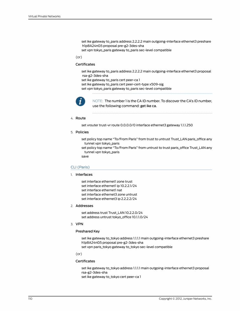
set ike gateway to_paris address 2.2.2.2 main outgoing-interface ethernet3 preshareh1p8A24nG5 proposal pre-g2-3des-shaset vpn tokyo_paris gateway to_paris sec-level compatible
(or)
Certificates
set ike gateway to_paris address 2.2.2.2 main outgoing-interface ethernet3 proposalrsa-g2-3des-shaset ike gateway to_paris cert peer-ca 1set ike gateway to_paris cert peer-cert-type x509-sigset vpn tokyo_paris gateway to_paris sec-level compatible
NOTE: The number 1 is the CA ID number. To discover the CA’s ID number,use the following command: get ike ca.
4. Route
set vrouter trust-vr route 0.0.0.0/0 interface ethernet3 gateway 1.1.1.250
5. Policies
set policy top name “To/From Paris” from trust to untrust Trust_LAN paris_office anytunnel vpn tokyo_paris
set policy top name “To/From Paris” from untrust to trust paris_office Trust_LAN anytunnel vpn tokyo_paris
save
CLI (Paris)
1. Interfaces
set interface ethernet1 zone trustset interface ethernet1 ip 10.2.2.1/24set interface ethernet1 natset interface ethernet3 zone untrustset interface ethernet3 ip 2.2.2.2/24
2. Addresses
set address trust Trust_LAN 10.2.2.0/24set address untrust tokyo_office 10.1.1.0/24
3. VPN
Preshared Key
set ike gateway to_tokyo address 1.1.1.1 main outgoing-interface ethernet3 preshareh1p8A24nG5 proposal pre-g2-3des-shaset vpn paris_tokyo gateway to_tokyo sec-level compatible
(or)
Certificates
set ike gateway to_tokyo address 1.1.1.1 main outgoing-interface ethernet3 proposalrsa-g2-3des-shaset ike gateway to_tokyo cert peer-ca 1
Copyright © 2012, Juniper Networks, Inc.110
Virtual Private Networks

set ike gateway to_tokyo cert peer-cert-type x509-sigset vpn paris_tokyo gateway to_tokyo tunnel proposal nopfs-esp-3des-sha
4. Route
set vrouter trust-vr route 0.0.0.0/0 interface ethernet3 gateway 2.2.2.250
5. Policies
set policy top name “To/From Tokyo” from trust to untrust Trust_LAN tokyo_officeany tunnel vpn paris_tokyoset policy top name “To/From Tokyo” from untrust to trust tokyo_office Trust_LANany tunnel vpn paris_tokyosave
Route-Based Site-to-Site VPN, Dynamic Peer
In this example, an AutoKey IKE VPN tunnel using either a preshared key or a pair of
certificates (one at each end of the tunnel) provides a secure connection between security
devices protecting the Tokyo and Paris offices. The Untrust zone interface for the Paris
security device has a static IP address. The ISP serving the Tokyo office assigns the IP
address for the Untrust zone interface dynamically through DHCP. Because only the Paris
security device has a fixed address for its Untrust zone, VPN traffic must originate from
hosts in the Tokyo office. After a tunnel has been established, traffic through the tunnel
can originate from either end. All security and tunnel zones are in the trust-vr.
Figure 34: Route-Based Site-to-Site VPN, Dynamic Peer
ParisTokyo
Topology of the zonesconfigured on the security
device in Tokyo
TrustZone
UntrustZone
Topology of the zonesconfigured on the security
device in Paris
TrustZone
Tunnel InterfaceTunnel.1
Tunnel InterfaceTunnel.1
UntrustZone
Tokyo
TokyoTrust Zone
eth1, 10.1.1.1/24
ParisTrust Zone
eth1, 10.2.2.1/24
VPN Tunnel
Internet
Paris
Outgoing InterfaceUntrust Zone
eth3 and gatewaydynamically assigned
by ISP
Outgoing InterfaceUntrust Zone
eth3, 2.2.2.2/24Gateway 2.2.2.250
DHCP Server2.1.1.5
The preshared key is h1p8A24nG5. It is assumed that both participants already have RSA
certificates from the certificate authority (CA) Verisign and that the email address
[email protected] appears in the local certificate on Device A. (For information about
obtaining and loading certificates, see “Certificates and CRLs” on page 39.) For the Phase 1
and Phase 2 security levels, you specify one Phase 1 proposal—either pre-g2-3des-sha
for the preshared key method or rsa-g2-3des-sha for certificates—and select the
“Compatible” set of proposals for Phase 2.
You enter three routes on the security devices at each end of the VPN tunnel:
111Copyright © 2012, Juniper Networks, Inc.
Chapter 4: Site-to-Site Virtual Private Networks

• A default route to the external router in the trust-vr
• A route to the destination through the tunnel interface
• A null route to the destination. You assign a higher metric (farther from zero) to the
null route so that it becomes the next-choice route to the destination. Then, if the state
of the tunnel interface changes to “down” and the route referencing that interface
becomes inactive, the security device uses the null route, which essentially drops any
traffic sent to it, rather than the default route, which forwards unencrypted traffic.
Finally, you configure policies to permit bidirectional traffic between the two sites.
WebUI (Tokyo)
1. Interfaces
Network > Interfaces > Edit (for ethernet1): Enter the following, then click Apply:
Zone Name: TrustStatic IP: (select this option when present)IP Address/Netmask: 10.1.1.1/24
Select the following, then click OK:
Interface Mode: NAT
Network > Interfaces > Edit (for ethernet3): Enter the following, then click Apply:
Zone Name: Untrust
Enter the following, then click OK:
Obtain IP using DHCP: (select)
NOTE: You cannot specify the IP address of the DHCP server through theWebUI; however, you can do so through the CLI.
Network > Interfaces > New Tunnel IF: Enter the following, then click OK:
Tunnel Interface Name: tunnel.1Zone (VR): Untrust (trust-vr)Unnumbered: (select)Interface: ethernet3 (trust-vr)
2. Addresses
Policy > Policy Elements > Addresses > List > New: Enter the following, then clickOK:
Address Name: Trust_LANIP Address/Domain Name:IP/Netmask: (select), 10.1.1.0/24
Zone: Trust
Policy > Policy Elements > Addresses > List > New: Enter the following, then clickOK:
Address Name: Paris_OfficeIP Address/Domain Name:IP/Netmask: (select), 10.2.2.0/24
Zone: Untrust
Copyright © 2012, Juniper Networks, Inc.112
Virtual Private Networks

3. VPN
VPNs > AutoKey Advanced > Gateway > New: Enter the following, then click OK:
Gateway Name: To_ParisSecurity Level: CustomRemote Gateway Type:Static IP Address: (select), IP Address/Hostname: 2.2.2.2
Preshared Key
Preshared Key: h1p8A24nG5Local ID: [email protected] Interface: ethernet3
> Advanced: Enter the following advanced settings, then click Return to return to the
basic Gateway configuration page:
Security Level: CustomPhase 1 Proposal (For Custom Security Level): pre-g2-3des-shaMode (Initiator): Aggressive
(or)
Certificates
Local ID: [email protected] Interface: ethernet3
NOTE: The U-FQDN “[email protected]”must appear in theSubjectAltName field in the certificate.
> Advanced: Enter the following advanced settings, then click Return to return to the
basic Gateway configuration page:
Security Level: CustomPhase 1 Proposal (For Custom Security Level): rsa-g2-3des-shaMode (Initiator): AggressivePreferred Certificate (optional):Peer CA: VerisignPeer Type: X509-SIG
VPNs > AutoKey IKE > New: Enter the following, then click OK:
VPNName: Tokyo_ParisSecurity Level: CompatibleRemote Gateway:Predefined: (select), To_Paris
> Advanced: Enter the following advanced settings, then click Return to return to the
basic AutoKey IKE configuration page:
Bind to: Tunnel Interface: (select), tunnel.1Proxy-ID: (select)
Local IP / Netmask: 10.1.1.0/24Remote IP / Netmask: 10.2.2.0/24Service: ANY
4. Routes
113Copyright © 2012, Juniper Networks, Inc.
Chapter 4: Site-to-Site Virtual Private Networks

Network > Routing > Routing Entries > trust-vr New: Enter the following, then click
OK:
Network Address/Netmask: 0.0.0.0/0Gateway: (select)Interface: ethernet3Gateway IP Address: 0.0.0.0
NOTE: The ISP provides the gateway IP address dynamically throughDHCP.
Network > Routing > Routing Entries > trust-vr New: Enter the following, then click
OK:
Network Address/Netmask: 10.2.2.0/24Gateway: (select)Interface: Tunnel.1Gateway IP Address: 0.0.0.0
Network > Routing > Routing Entries > trust-vr New: Enter the following, then click
OK:
Network Address/Netmask: 10.2.2.0/24Gateway: (select)Interface: NullGateway IP Address: 0.0.0.0Metric: 10
5. Policies
Policies > (From: Trust, To: Untrust) New: Enter the following, then click OK:
Source Address:Address Book Entry: (select), Trust_LAN
Destination Address:Address Book Entry: (select), Paris_Office
Service: AnyAction: PermitPosition at Top: (select)
Policies > (From: Untrust, To: Trust) New: Enter the following, then click OK:
Source Address:Address Book Entry: (select), Paris_Office
Destination Address:Address Book Entry: (select), Trust_LAN
Service: AnyAction: PermitPosition at Top: (select)
WebUI (Paris)
1. Interfaces
Network > Interfaces > Edit (for ethernet1): Enter the following, then click Apply:
Copyright © 2012, Juniper Networks, Inc.114
Virtual Private Networks

Zone Name: TrustStatic IP: (select this option when present)IP Address/Netmask: 10.2.2.1/24
Select the following, then click OK:
Interface Mode: NAT
Network > Interfaces > Edit (for ethernet3): Enter the following, then click OK:
Zone Name: UntrustStatic IP: (select this option when present)IP Address: 2.2.2.2/24
Network > Interfaces > New Tunnel IF: Enter the following, then click OK:
Tunnel Interface Name: tunnel.1Zone (VR): Untrust (trust-vr)Unnumbered: (select)Interface: ethernet3 (trust-vr)
2. Addresses
Policy > Policy Elements > Addresses > List > New: Enter the following, then clickOK:
Address Name: Trust_LANIP Address/Domain Name:IP/Netmask: (select), 10.2.2.0/24
Zone: Trust
Policy > Policy Elements > Addresses > List > New: Enter the following, then clickOK:
Address Name: Tokyo_OfficeIP Address/Domain Name:IP/Netmask: (select), 10.1.1.0/24
Zone: Untrust
3. VPN
VPNs > AutoKey Advanced > Gateway > New: Enter the following, then click OK:
Gateway Name: To_TokyoSecurity Level: CustomRemote Gateway Type:Dynamic IP Address: (select), Peer ID: [email protected]
Preshared Key
Preshared Key
Preshared Key: h1p8A24nG5Outgoing Interface: ethernet3
> Advanced: Enter the following advanced settings, then click Return to return to the
basic Gateway configuration page:
Security Level: CustomPhase 1 Proposal (For Custom Security Level): pre-g2-3des-shaMode (Initiator): Aggressive
(or)
Certificates
115Copyright © 2012, Juniper Networks, Inc.
Chapter 4: Site-to-Site Virtual Private Networks
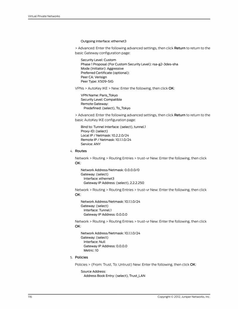
Outgoing Interface: ethernet3
> Advanced: Enter the following advanced settings, then click Return to return to the
basic Gateway configuration page:
Security Level: CustomPhase 1 Proposal (For Custom Security Level): rsa-g2-3des-shaMode (Initiator): AggressivePreferred Certificate (optional):Peer CA: VerisignPeer Type: X509-SIG
VPNs > AutoKey IKE > New: Enter the following, then click OK:
VPNName: Paris_TokyoSecurity Level: CompatibleRemote Gateway:Predefined: (select), To_Tokyo
> Advanced: Enter the following advanced settings, then click Return to return to the
basic AutoKey IKE configuration page:
Bind to: Tunnel Interface: (select), tunnel.1Proxy-ID: (select)Local IP / Netmask: 10.2.2.0/24Remote IP / Netmask: 10.1.1.0/24Service: ANY
4. Routes
Network > Routing > Routing Entries > trust-vr New: Enter the following, then click
OK:
Network Address/Netmask: 0.0.0.0/0Gateway: (select)Interface: ethernet3Gateway IP Address: (select), 2.2.2.250
Network > Routing > Routing Entries > trust-vr New: Enter the following, then click
OK:
Network Address/Netmask: 10.1.1.0/24Gateway: (select)Interface: Tunnel.1Gateway IP Address: 0.0.0.0
Network > Routing > Routing Entries > trust-vr New: Enter the following, then click
OK:
Network Address/Netmask: 10.1.1.0/24Gateway: (select)Interface: NullGateway IP Address: 0.0.0.0Metric: 10
5. Policies
Policies > (From: Trust, To: Untrust) New: Enter the following, then click OK:
Source Address:Address Book Entry: (select), Trust_LAN
Copyright © 2012, Juniper Networks, Inc.116
Virtual Private Networks

Destination Address:Address Book Entry: (select), Tokyo_Office
Service: AnyAction: PermitPosition at Top: (select)
Policies > (From: Untrust, To: Trust) New: Enter the following, then click OK:
Source Address:Address Book Entry: (select), Tokyo_Office
Destination Address:Address Book Entry: (select), Trust_LAN
Service: AnyAction: PermitPosition at Top: (select)
CLI (Tokyo)
1. Interfaces
set interface ethernet1 zone trustset interface ethernet1 ip 10.1.1.1/24set interface ethernet1 natset interface ethernet3 zone untrustset interface ethernet3 dhcp clientset interface ethernet3 dhcp client settings server 1.1.1.5set interface tunnel.1 zone untrustset interface tunnel.1 ip unnumbered interface ethernet3
2. Addresses
set address trust Trust_LAN 10.1.1.0/24set address untrust Paris_Office 10.2.2.0/24
3. VPN
Preshared Key
set ike gateway To_Paris address 2.2.2.2 aggressive local-id [email protected] ethernet3 preshare h1p8A24nG5 proposal pre-g2-3des-shaset vpn Tokyo_Paris gateway To_Paris tunnel sec-level compatibleset vpn Tokyo_Paris bind interface tunnel.1set vpn Tokyo_Paris proxy-id local-ip 10.1.1.0/24 remote-ip 10.2.2.0/24 any
(or)
Certificates
set ike gateway To_Paris address 2.2.2.2 aggressive local-id [email protected] ethernet3 proposal rsa-g2-3des-shaset ike gateway To_Paris cert peer-ca 1set ike gateway To_Paris cert peer-cert-type x509-sigset vpn Tokyo_Paris gateway To_Paris tunnel sec-level compatibleset vpn Tokyo_Paris bind interface tunnel.1set vpn Tokyo_Paris proxy-id local-ip 10.1.1.0/24 remote-ip 10.2.2.0/24 any
117Copyright © 2012, Juniper Networks, Inc.
Chapter 4: Site-to-Site Virtual Private Networks

NOTE: The U-FQDN “[email protected]”must appear in theSubjectAltName field in the certificate.
The number 1 is the CA ID number. To discover the CA’s ID number, usethe following command: get ike ca.
4. Routes
set vrouter trust-vr route 0.0.0.0/0 interface ethernet3set vrouter trust-vr route 10.2.2.0/24 interface tunnel.1set vrouter trust-vr route 10.2.2.0/24 interface null metric 10
NOTE: The ISP provides the gateway IP address dynamically throughDHCP, so you cannot specify it here.
5. Policies
set policy top from trust to untrust Trust_LAN Paris_Office any permitset policy top from untrust to trust Paris_Office Trust_LAN any permitsave
CLI (Paris)
1. Interfaces
set interface ethernet1 zone trustset interface ethernet1 ip 10.2.2.1/24set interface ethernet1 natset interface ethernet3 zone untrustset interface ethernet3 ip 2.2.2.2/24set interface tunnel.1 zone untrustset interface tunnel.1 ip unnumbered interface ethernet3
2. Addresses
set address trust Trust_LAN 10.2.2.0/24set address untrust Tokyo_Office 10.1.1.0/24
3. VPN
Preshared Key
set ike gateway To_Tokyo dynamic [email protected] aggressive outgoing-interfaceethernet3 preshare h1p8A24nG5 proposal pre-g2-3des-shaset vpn Paris_Tokyo gateway To_Tokyo tunnel sec-level compatibleset vpn Paris_Tokyo bind interface tunnel.1set vpn Paris_Tokyo proxy-id local-ip 10.2.2.0/24 remote-ip 10.1.1.0/24 any
(or)
Certificates
set ike gateway To_Tokyo dynamic [email protected] aggressive outgoing-interfaceethernet3 proposal rsa-g2-3des-shaset ike gateway To_Tokyo cert peer-ca 1
Copyright © 2012, Juniper Networks, Inc.118
Virtual Private Networks

set ike gateway To_Tokyo cert peer-cert-type x509-sigset vpn Paris_Tokyo gateway To_Tokyo tunnel sec-level compatibleset vpn Paris_Tokyo bind interface tunnel.1set vpn Paris_Tokyo proxy-id local-ip 10.2.2.0/24 remote-ip 10.1.1.0/24 any
NOTE: The number 1 is the CA ID number. To discover the CA’s ID number,use the following command: get ike ca.
4. Routes
set vrouter trust-vr route 0.0.0.0/0 interface ethernet3 gateway 2.2.2.250set vrouter trust-vr route 10.1.1.0/24 interface tunnel.1set vrouter trust-vr route 10.1.1.0/24 interface null metric 10
5. Policies
set policy top from trust to untrust Trust_LAN Tokyo_Office any permitset policy top from untrust to trust Tokyo_Office Trust_LAN any permitsave
Policy-Based Site-to-Site VPN, Dynamic Peer
In this example, a VPN tunnel securely connects the users in the Trust zone behind
Device A to the mail server in the corporate DMZ zone, protected by Device B. The Untrust
zone interface for Device B has a static IP address. The ISP serving Device A assigns the
IP address for its Untrust zone interface dynamically through DHCP. Because only Device B
has a fixed address for its Untrust zone, VPN traffic must originate from hosts behind
Device A. After Device A has established the tunnel, traffic through the tunnel can originate
from either end. All zones are in the trust-vr routing domain.
Figure 35: Policy-Based Site-to-Site VPN, Dynamic Peer
ID
Phil
User Name: pmasonPassword: Nd4syst4
AuthenticationUser
Topology of the zonesconfigured on Device-A at the
branch office.
TrustZone
UntrustZone
A
Topology of the zonesconfigured on Device-B at the
corporate site.
DMZZone
UntrustZone
A BB
Outgoing InterfaceUntrust Zone
eth3 and gatewaydynamically assigned
by ISP
Outgoing InterfaceUntrust Zone
eth3, 2.2.2.2/24Gateway 2.2.2.250
Branch OfficeTrust Zone
eth1, 10.1.1.1/24
Corporate OfficeDMZ Zone
eth2, 3.3.3.3/24
VPN Tunnel
Internet
IDENTRequest
Mail Server3.3.3.5
Note:Before making an SMTP or a POP3 connection to thecorporate mail server, Phil must first initiate an HTTP, anFTP, or a Telnet connection so that Device-A canauthenticate him.
SMTP or POP3Request DHCP Server
2.1.1.5
Device-A Device-B
119Copyright © 2012, Juniper Networks, Inc.
Chapter 4: Site-to-Site Virtual Private Networks

In this example, the local auth user Phil (login name: pmason; password: Nd4syst4)
wants to get his email from the mail server at the corporate site. When he attempts to
do so, he is authenticated twice: first, Device A authenticates him locally before allowing
traffic from him through the tunnel; second, the mail server program authenticates him,
sending the IDENT request through the tunnel.
NOTE: Because Phil is an authentication user, before he canmake an SMTPof POP3 request, hemust first initiate an HTTP, FTP, or Telnet connectionso thatDeviceAcan respondwitha firewall user/loginprompt toauthenticatehim. After Device A authenticates him, he has permission to contact thecorporatemail server through the VPN tunnel.
Themail server can send the IDENT request through the tunnel only if theDevice A and B administrators add a custom service for it (TCP, port 113) andset up policies allowing that traffic through the tunnel to the 10.10.10.0/24subnet.
The preshared key is h1p8A24nG5. It is assumed that both participants already have RSA
certificates from the certificate authority (CA) Verisign and that the email address
[email protected] appears in the local certificate on Device A. (For information about
obtaining and loading certificates, see “Certificates and CRLs” on page 39.) For the Phase 1
and Phase 2 security levels, you specify one Phase 1 proposal—either pre-g2-3des-sha
for the preshared key method or rsa-g2-3des-sha for certificates—and select the
predefined “Compatible” set of proposals for Phase 2.
WebUI (Device A)
1. Interfaces
Network > Interfaces > Edit (for ethernet1): Enter the following, then click Apply:
Zone Name: TrustStatic IP: (select this option when present)IP Address/Netmask: 10.1.1.1/24
Select the following, then click OK:
Interface Mode: NAT
Network > Interfaces > Edit (for ethernet3): Enter the following, then click OK:
Zone Name: UntrustObtain IP using DHCP: (select)
NOTE: You cannot specify the IP address of the DHCP server through theWebUI; however, you can do so through the CLI.
2. User
Objects > Users > Local > New: Enter the following, then click OK:
Copyright © 2012, Juniper Networks, Inc.120
Virtual Private Networks

User Name: pmasonStatus: EnableAuthentication User: (select)User Password: Nd4syst4Confirm Password: Nd4syst4
3. Addresses
Policy > Policy Elements > Addresses > List > New: Enter the following, then clickOK:
Address Name: Trusted_networkIP Address/Domain Name:IP/Netmask: (select), 10.1.1.0/24
Zone: Trust
Policy > Policy Elements > Addresses > List > New: Enter the following, then clickOK:
Address Name: Mail_ServerIP Address/Domain Name:IP/Netmask: (select), 3.3.3.5/32
Zone: Untrust
4. Services
Policy > Policy Elements > Services > Custom > New: Enter the following, then click
OK:
Service Name: IdentService Timeout:Use protocol default: (select)
Transport Protocol: TCP (select)Source Port: Low 0, High 65535Destination Port: Low 113, High 113
Policy > Policy Elements > Services > Group > New: Enter the following, move the
following services, then click OK:
Group Name: Remote_MailGroupMembers << Available Members:HTTPFTPTelnetIdentMAILPOP3
5. VPN
VPNs > AutoKey Advanced > Gateway > New: Enter the following, then click OK:
Gateway Name: To_MailSecurity Level: CustomRemote Gateway Type:Static IP Address: (select), IP Address/Hostname: 2.2.2.2
Preshared Key
Preshared Key: h1p8A24nG5Local ID: [email protected] Interface: ethernet3
121Copyright © 2012, Juniper Networks, Inc.
Chapter 4: Site-to-Site Virtual Private Networks

> Advanced: Enter the following advanced settings, then click Return to return to the
basic Gateway configuration page:
Security Level: CustomPhase 1 Proposal (For Custom Security Level): pre-g2-3des-shaMode (Initiator): Aggressive
(or)
Certificates
Local ID: [email protected] Interface: ethernet3
> Advanced: Enter the following advanced settings, then click Return to return to the
basic Gateway configuration page:
Security Level: CustomPhase 1 Proposal (For Custom Security Level): rsa-g2-3des-shaMode (Initiator): AggressivePreferred Certificate (optional):Peer CA: VerisignPeer Type: X509-SIG
VPNs > AutoKey IKE > New: Enter the following, then click OK:
Name: branch_corpSecurity Level: CompatibleRemote Gateway Tunnel: To_Mail
6. Route
Network > Routing > Routing Entries > trust-vr New: Enter the following, then click
OK:
Network Address/Netmask: 0.0.0.0/0Gateway: (select)Interface: ethernet3Gateway IP Address: 0.0.0.0
NOTE: The ISP provides the gateway IP address dynamically throughDHCP.
7. Policies
Policies > (From: Trust, To: Untrust) New: Enter the following, then click OK:
Source Address:Address Book Entry: (select), Trusted_network
Destination Address:Address Book Entry: (select), Mail_Server
Service: Remote_MailAction: TunnelVPN Tunnel: branch_corpModify matching bidirectional VPN policy: (select)Position at Top: (select)
Copyright © 2012, Juniper Networks, Inc.122
Virtual Private Networks

> Advanced: Enter the following advanced settings, then click Return to return to the
basic Policy configuration page:
Authentication: (select)Auth Server: LocalUser: (select), Local Auth User - pmason
WebUI (Device B)
1. Interfaces
Network > Interfaces > Edit (for ethernet2): Enter the following, then click OK:
Zone Name: DMZStatic IP: (select this option when present)IP Address/Netmask: 3.3.3.3/24
Network > Interfaces > Edit (for ethernet3): Enter the following, then click OK:
Zone Name: UntrustStatic IP: (select this option when present)IP Address/Netmask: 2.2.2.2/24
2. Addresses
Policy > Policy Elements > Addresses > List > New: Enter the following, then clickOK:
Address Name: Mail ServerIP Address/Domain Name:IP/Netmask: (select), 3.3.3.5/32
Zone: DMZ
Policy > Policy Elements > Addresses > List > New: Enter the following, then clickOK:
Address Name: branch officeIP Address/Domain Name:IP/Netmask: (select), 10.1.1.0/24
Zone: Untrust
3. Services
Policy > Policy Elements > Services > Custom > New: Enter the following, then click
OK:
Service Name: IdentService Timeout:Use protocol default: (select)
Transport Protocol: TCP (select)Source Port: Low 0, High 65535Destination Port: Low 113, High 113
Policy > Policy Elements > Services > Groups > New: Enter the following, move the
following services, then click OK:
Group Name: Remote_MailGroupMembers << Available Members:IdentMAILPOP3
4. VPN
123Copyright © 2012, Juniper Networks, Inc.
Chapter 4: Site-to-Site Virtual Private Networks
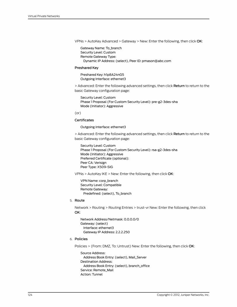
VPNs > AutoKey Advanced > Gateway > New: Enter the following, then click OK:
Gateway Name: To_branchSecurity Level: CustomRemote Gateway Type:Dynamic IP Address: (select), Peer ID: [email protected]
Preshared Key
Preshared Key: h1p8A24nG5Outgoing Interface: ethernet3
> Advanced: Enter the following advanced settings, then click Return to return to the
basic Gateway configuration page:
Security Level: CustomPhase 1 Proposal (For Custom Security Level): pre-g2-3des-shaMode (Initiator): Aggressive
(or)
Certificates
Outgoing Interface: ethernet3
> Advanced: Enter the following advanced settings, then click Return to return to the
basic Gateway configuration page:
Security Level: CustomPhase 1 Proposal (For Custom Security Level): rsa-g2-3des-shaMode (Initiator): AggressivePreferred Certificate (optional):Peer CA: VerisignPeer Type: X509-SIG
VPNs > AutoKey IKE > New: Enter the following, then click OK:
VPNName: corp_branchSecurity Level: CompatibleRemote Gateway:Predefined: (select), To_branch
5. Route
Network > Routing > Routing Entries > trust-vr New: Enter the following, then click
OK:
Network Address/Netmask: 0.0.0.0/0Gateway: (select)Interface: ethernet3Gateway IP Address: 2.2.2.250
6. Policies
Policies > (From: DMZ, To: Untrust) New: Enter the following, then click OK:
Source Address:Address Book Entry: (select), Mail_Server
Destination Address:Address Book Entry: (select), branch_office
Service: Remote_MailAction: Tunnel
Copyright © 2012, Juniper Networks, Inc.124
Virtual Private Networks

VPN Tunnel: corp_branchModify matching bidirectional VPN policy: (select)Position at Top: (select)
CLI (Device A)
1. Interfaces
set interface ethernet1 zone trustset interface ethernet1 ip 10.1.1.1/24set interface ethernet1 natset interface ethernet3 zone untrustset interface ethernet3 dhcp clientset interface ethernet3 dhcp client settings server 1.1.1.5
2. User
set user pmason password Nd4syst4
3. Addresses
set address trust “trusted network” 10.1.1.0/24set address untrust “ mail server” 3.3.3.5/32
4. Services
set service ident protocol tcp src-port 0-65535 dst-port 113-113set group service remote_mailset group service remote_mail add httpset group service remote_mail add ftpset group service remote_mail add telnetset group service remote_mail add identset group service remote_mail addmailset group service remote_mail add pop3
5. VPN
Preshared Key
set ike gateway to_mail address 2.2.2.2 aggressive local-id [email protected] ethernet3 preshare h1p8A24nG5 proposal pre-g2-3des-shaset vpn branch_corp gateway to_mail sec-level compatible
(or)
Certificates
set ike gateway to_mail address 2.2.2.2 aggressive local-id [email protected] ethernet3 proposal rsa-g2-3des-sha
set ike gateway to_mail cert peer-ca 1set ike gateway to_mail cert peer-cert-type x509-sigset vpn branch_corp gateway to_mail sec-level compatible
NOTE: The U-FQDN “[email protected]”must appear in theSubjectAltName field in the certificate.
The number 1 is the CA ID number. To discover the CA’s ID number, usethe following command: get ike ca.
125Copyright © 2012, Juniper Networks, Inc.
Chapter 4: Site-to-Site Virtual Private Networks

6. Route
set vrouter trust-vr route 0.0.0.0/0 interface ethernet3
NOTE: The ISP provides the gateway IP address dynamically throughDHCP.
7. Policies
setpolicy top fromtrust tountrust “trustednetwork” “mail server” remote_mail tunnelvpn branch_corp auth server Local user pmasonsetpolicy top fromuntrust to trust “mail server” “trustednetwork” remote_mail tunnelvpn branch_corpsave
CLI (Device B)
1. Interfaces
set interface ethernet2 zone dmzset interface ethernet2 ip 3.3.3.3/24set interface ethernet3 zone untrustset interface ethernet3 ip 2.2.2.2/24
2. Addresses
set address dmz “mail server” 3.3.3.5/32set address untrust “ branch office” 10.1.1.0/24
3. Services
set service ident protocol tcp src-port 0-65535 dst-port 113-113set group service remote_mailset group service remote_mail add identset group service remote_mail addmailset group service remote_mail add pop3
4. VPN
Preshared Key
set ike gateway to_branchdynamic [email protected] outgoing-interfaceethernet3 preshare h1p8A24nG5 proposal pre-g2-3des-shaset vpn corp_branch gateway to_branch tunnel sec-level compatible
(or)
Certificates
set ike gateway to_branchdynamic [email protected] outgoing-interfaceethernet3 proposal rsa-g2-3des-shaset ike gateway to_branch cert peer-ca 1set ike gateway to_branch cert peer-cert-type x509-sigset vpn corp_branch gateway to_branch sec-level compatible
NOTE: The number 1 is the CA ID number. To discover the CA’s ID number,use the following command: get ike ca.
Copyright © 2012, Juniper Networks, Inc.126
Virtual Private Networks

5. Route
set vrouter trust-vr route 0.0.0.0/0 interface ethernet3 gateway 2.2.2.250
6. Policies
set policy top from dmz to untrust “mail server” “branch office” remote_mail tunnelvpn corp_branchset policy top from untrust to dmz “branch office” “mail server” remote_mail tunnelvpn corp_branchsave
Route-Based Site-to-Site VPN, Manual Key
In this example, a Manual Key tunnel provides a secure communication channel between
offices in Tokyo and Paris. The Trust zones at each site are in NAT mode. The addresses
are as follows:
• Tokyo:
• Trust zone interface (ethernet1): 10.1.1.1/24
• Untrust zone interface (ethernet3): 1.1.1.1/24
• Paris:
• Trust zone interface (ethernet1): 10.2.2.1/24
• Untrust zone interface (ethernet3): 2.2.2.2/24
The Trust and Untrust security zones are all in the trust-vr routing domain. The Untrust
zone interface (ethernet3) serves as the outgoing interface for the VPN tunnel.
Figure 36: Route-Based Site-to-Site VPN, Manual Key
Topology of the zonesconfigured on the security
device in Tokyo.
TrustZone
UntrustZone
Topology of the zonesconfigured on the security
device in Paris.
TrustZone
Tunnel InterfaceTunnel.1
Tunnel InterfaceTunnel.1
UntrustZone
Tokyo
Outgoing InterfaceUntrust Zone
eth3, 1.1.1.1/24Gateway 1.1.1.250
Outgoing InterfaceUntrust Zone
eth3, 2.2.2.2/24Gateway 2.2.2.250Tokyo
Trust Zoneeth1, 10.1.1.1/24
ParisTrust Zone
eth1, 10.2.2.1/24
VPN Tunnel
Internet
ParisParisTokyo
To set up the tunnel, perform the following steps on the security devices at both ends of
the tunnel:
127Copyright © 2012, Juniper Networks, Inc.
Chapter 4: Site-to-Site Virtual Private Networks

1. Assign IP addresses to the physical interfaces bound to the security zones and to the
tunnel interface.
2. Configure the VPN tunnel, designate its outgoing interface in the Untrust zone, and
bind it to the tunnel interface.
3. Enter the IP addresses for the local and remote endpoints in the address books for
the Trust and Untrust zones.
4. Enter a default route to the external router in the trust-vr, a route to the destination
through the tunnel interface, and a null route to the destination. You assign a higher
metric (farther from zero) to the null route so that it becomes the next-choice route
to the destination. Then, if the state of the tunnel interface changes to “down” and
the route referencing that interface becomes inactive, the security device uses the
null route, which essentially drops any traffic sent to it, rather than the default route,
which forwards unencrypted traffic.
5. Set up policies for VPN traffic to pass between each site.
WebUI (Tokyo)
1. Interfaces
Network > Interfaces > Edit (for ethernet1): Enter the following, then click Apply:
Zone Name: TrustStatic IP: (select this option when present)IP Address/Netmask: 10.1.1.1/24
Select the following, then click OK:
Interface Mode: NAT
Network > Interfaces > Edit (for ethernet3): Enter the following, then click OK:
Zone Name: UntrustStatic IP: (select this option when present)IP Address/Netmask: 1.1.1.1/24
Network > Interfaces > New Tunnel IF: Enter the following, then click OK:
Tunnel Interface Name: tunnel.1Zone (VR): Untrust (trust-vr)Unnumbered: (select)Interface: ethernet3 (trust-vr)
2. Addresses
Policy > Policy Elements > Addresses > List > New: Enter the following, then clickOK:
Address Name: Trust_LANIP Address/Domain Name:IP/Netmask: (select), 10.1.1.0/24
Zone: Trust
Policy > Policy Elements > Addresses > List > New: Enter the following, then clickOK:
Address Name: Paris_OfficeIP Address/Domain Name:
Copyright © 2012, Juniper Networks, Inc.128
Virtual Private Networks

IP/Netmask: (select), 10.2.2.0/24Zone: Untrust
3. VPN
VPNs > Manual Key > New: Enter the following, then click OK:
VPN Tunnel Name: Tokyo_ParisGateway IP: 2.2.2.2Security Index: 3020 (Local), 3030 (Remote)Outgoing Interface: ethernet3ESP-CBC: (select)Encryption Algorithm: 3DES-CBCGenerate Key by Password: asdlk24234Authentication Algorithm: SHA-1Generate Key by Password: PNas134a
> Advanced: Enter the following advanced settings, then click Return to return to the
basic Manual Key tunnel configuration page:
Bind to: Tunnel Interface, tunnel.1
4. Routes
Network > Routing > Routing Entries > trust-vr New: Enter the following, then click
OK:
Network Address/Netmask: 0.0.0.0/0Gateway: (select)Interface: ethernet3Gateway IP Address: 1.1.1.250
Network > Routing > Routing Entries > trust-vr New: Enter the following, then click
OK:
Network Address/Netmask: 10.2.2.0/24Gateway: (select)Interface: tunnel.1Gateway IP Address: 0.0.0.0
Network > Routing > Routing Entries > trust-vr New: Enter the following, then click
OK:
Network Address/Netmask: 10.2.2.0/24Gateway: (select)Interface: NullGateway IP Address: 0.0.0.0Metric: 10
5. Policies
Policies > (From: Trust, To: Untrust) New: Enter the following, then click OK:
Name: To ParisSource Address:Address Book Entry: (select), Trust_LAN
Destination Address:Address Book Entry: (select), Paris_Office
Service: ANYAction: PermitPosition at Top: (select)
129Copyright © 2012, Juniper Networks, Inc.
Chapter 4: Site-to-Site Virtual Private Networks

Policies > (From: Untrust, To: Trust) New: Enter the following, then click OK:
Name: From ParisSource Address:Address Book Entry: (select), Paris_Office
Destination Address:Address Book Entry: (select), Trust_LAN
Service: ANYAction: PermitPosition at Top: (select)
WebUI (Paris)
1. Interfaces
Network > Interfaces > Edit (for ethernet1): Enter the following, then click Apply:
Zone Name: TrustStatic IP: (select this option when present)IP Address/Netmask: 10.2.2.1/24
Select the following, then click OK:
Interface Mode: NAT
Network > Interfaces > Edit (for ethernet3): Enter the following, then click OK:
Zone Name: UntrustStatic IP: (select this option when present)IP Address/Netmask: 2.2.2.2/24
Network > Interfaces > New Tunnel IF: Enter the following, then click OK:
Tunnel Interface Name: tunnel.1Zone (VR): Untrust (trust-vr)Unnumbered: (select)Interface: ethernet3 (trust-vr)
2. Addresses
Policy > Policy Elements > Addresses > List > New: Enter the following, then clickOK:
Address Name: Trust_LANIP Address/Domain Name:IP/Netmask: (select), 10.2.2.0/24
Zone: Trust
Policy > Policy Elements > Addresses > List > New: Enter the following, then clickOK:
Address Name: Tokyo_OfficeIP Address/Domain Name:IP/Netmask: (select), 10.1.1.0/24
Zone: Untrust
3. VPN
VPNs > Manual Key > New: Enter the following, then click OK:
VPN Tunnel Name: Paris_TokyoGateway IP: 1.1.1.1Security Index: 3030 (Local), 3020 (Remote)Outgoing Interface: ethernet3
Copyright © 2012, Juniper Networks, Inc.130
Virtual Private Networks

ESP-CBC: (select)Encryption Algorithm: 3DES-CBCGenerate Key by Password: asdlk24234Authentication Algorithm: SHA-1Generate Key by Password: PNas134a
> Advanced: Enter the following advanced settings, then click Return to return to the
basic Manual Key tunnel configuration page:
Bind to: Tunnel Interface, tunnel.1
4. Routes
Network > Routing > Routing Entries > trust-vr New: Enter the following, then click
OK:
Network Address/Netmask: 0.0.0.0/0Gateway: (select)Interface: ethernet3Gateway IP Address: 2.2.2.250
Network > Routing > Routing Entries > trust-vr New: Enter the following, then click
OK:
Network Address/Netmask: 10.1.1.0/24Gateway: (select)Interface: tunnel.1Gateway IP Address: 0.0.0.0
Network > Routing > Routing Entries > trust-vr New: Enter the following, then click
OK:
Network Address/Netmask: 10.1.1.0/24Gateway: (select)Interface: NullGateway IP Address: 0.0.0.0Metric: 10
5. Policies
Policies > (From: Trust, To: Untrust) New: Enter the following, then click OK:
Name: To_TokyoSource Address:Address Book Entry: (select), Trust_LAN
Destination Address:Address Book Entry: (select), Tokyo_Office
Service: ANYAction: PermitPosition at Top: (select)
Policies > (From: Untrust, To: Trust) New: Enter the following, then click OK:
Name: From_TokyoSource Address:Address Book Entry: (select), Tokyo_Office
Destination Address:Address Book Entry: (select), Trust_LAN
Service: ANY
131Copyright © 2012, Juniper Networks, Inc.
Chapter 4: Site-to-Site Virtual Private Networks

Action: PermitPosition at Top: (select)
CLI (Tokyo)
1. Interfaces
set interface ethernet1 zone trustset interface ethernet1 ip 10.1.1.1/24set interface ethernet1 natset interface ethernet3 zone untrustset interface ethernet3 ip 1.1.1.1/24set interface tunnel.1 zone untrustset interface tunnel.1 ip unnumbered interface ethernet3
2. Addresses
set address trust Trust_LAN 10.1.1.0/24set address untrust Paris_Office 10.2.2.0/24
3. VPN
set vpnTokyo_Parismanual 30203030gateway2.2.2.2 outgoing-interfaceethernet3esp 3des password asdlk24234 auth sha-1 password PNas134aset vpn Tokyo_Paris bind interface tunnel.1
4. Routes
set vrouter trust-vr route 0.0.0.0/0 interface ethernet3 gateway 1.1.1.250set vrouter trust-vr route 10.2.2.0/24 interface tunnel.1set vrouter trust-vr route 10.2.2.0/24 interface null metric 10
5. Policies
set policy topname “ToParis” fromtrust to untrust Trust_LANParis_Office anypermitset policy top name “From Paris” from untrust to trust Paris_Office Trust_LAN anypermitsave
CLI (Paris)
1. Interfaces
set interface ethernet1 zone trustset interface ethernet1 ip 10.2.2.1/24set interface ethernet1 natset interface ethernet3 zone untrustset interface ethernet3 ip 2.2.2.2/24set interface tunnel.1 zone untrustset interface tunnel.1 ip unnumbered interface ethernet3
2. Addresses
set address trust Trust_LAN 10.2.2.0/24set address untrust Tokyo_Office 10.1.1.0/24
3. VPN
set vpn Paris_Tokyomanual 3030 3020 gateway 1.1.1.1 outgoing-interface ethernet3esp 3des password asdlk24234 auth sha-1 password PNas134aset vpn Paris_Tokyo bind interface tunnel.1
Copyright © 2012, Juniper Networks, Inc.132
Virtual Private Networks
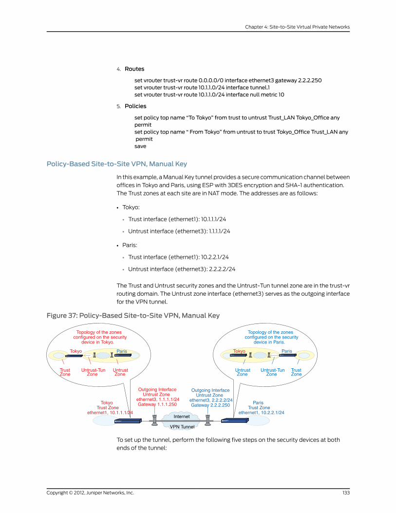
4. Routes
set vrouter trust-vr route 0.0.0.0/0 interface ethernet3 gateway 2.2.2.250set vrouter trust-vr route 10.1.1.0/24 interface tunnel.1set vrouter trust-vr route 10.1.1.0/24 interface null metric 10
5. Policies
set policy top name “To Tokyo” from trust to untrust Trust_LAN Tokyo_Office anypermitset policy top name “ From Tokyo” from untrust to trust Tokyo_Office Trust_LAN anypermitsave
Policy-Based Site-to-Site VPN, Manual Key
In this example, a Manual Key tunnel provides a secure communication channel between
offices in Tokyo and Paris, using ESP with 3DES encryption and SHA-1 authentication.
The Trust zones at each site are in NAT mode. The addresses are as follows:
• Tokyo:
• Trust interface (ethernet1): 10.1.1.1/24
• Untrust interface (ethernet3): 1.1.1.1/24
• Paris:
• Trust interface (ethernet1): 10.2.2.1/24
• Untrust interface (ethernet3): 2.2.2.2/24
The Trust and Untrust security zones and the Untrust-Tun tunnel zone are in the trust-vr
routing domain. The Untrust zone interface (ethernet3) serves as the outgoing interface
for the VPN tunnel.
Figure 37: Policy-Based Site-to-Site VPN, Manual Key
Topology of the zonesconfigured on the security
device in Tokyo.
TrustZone
Untrust-TunZone
UntrustZone
Tokyo
Topology of the zonesconfigured on the security
device in Paris.
TrustZone
Untrust-TunZone
UntrustZone
Tokyo ParisParis
Outgoing InterfaceUntrust Zone
ethernet3, 1.1.1.1/24Gateway 1.1.1.250
Outgoing InterfaceUntrust Zone
ethernet3, 2.2.2.2/24Gateway 2.2.2.250Tokyo
Trust Zoneethernet1, 10.1.1.1/24
ParisTrust Zone
ethernet1, 10.2.2.1/24
VPN Tunnel
Internet
To set up the tunnel, perform the following five steps on the security devices at both
ends of the tunnel:
133Copyright © 2012, Juniper Networks, Inc.
Chapter 4: Site-to-Site Virtual Private Networks
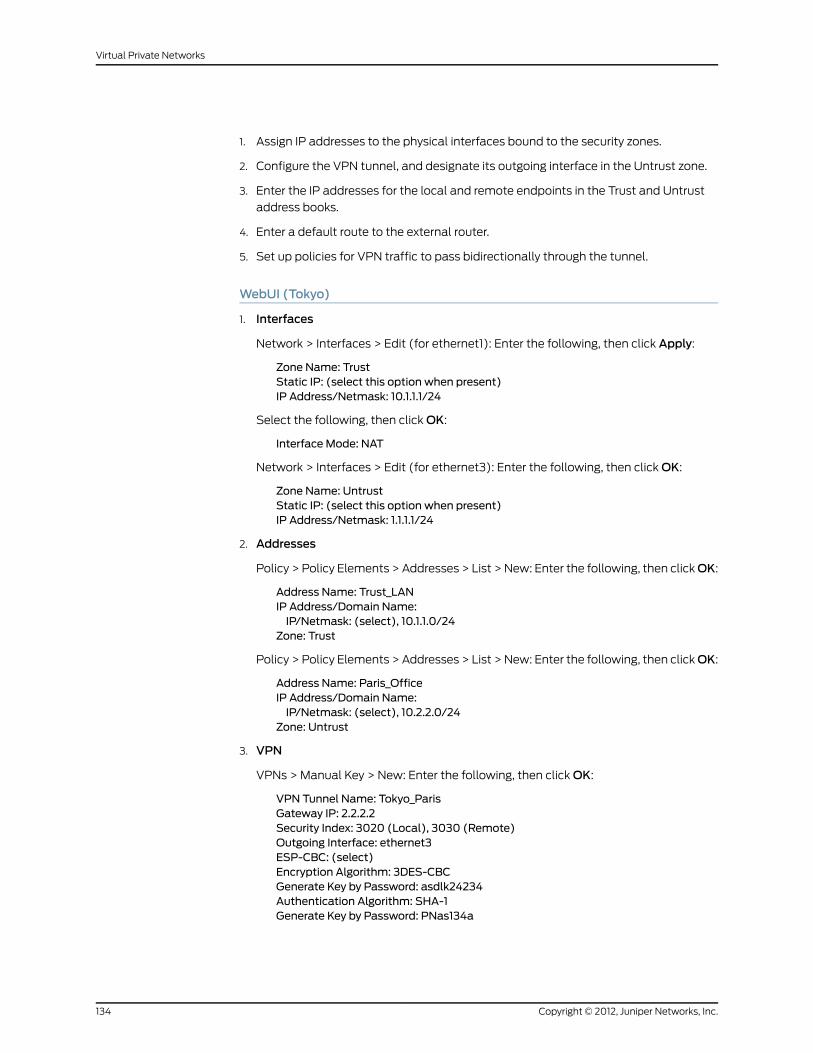
1. Assign IP addresses to the physical interfaces bound to the security zones.
2. Configure the VPN tunnel, and designate its outgoing interface in the Untrust zone.
3. Enter the IP addresses for the local and remote endpoints in the Trust and Untrust
address books.
4. Enter a default route to the external router.
5. Set up policies for VPN traffic to pass bidirectionally through the tunnel.
WebUI (Tokyo)
1. Interfaces
Network > Interfaces > Edit (for ethernet1): Enter the following, then click Apply:
Zone Name: TrustStatic IP: (select this option when present)IP Address/Netmask: 10.1.1.1/24
Select the following, then click OK:
Interface Mode: NAT
Network > Interfaces > Edit (for ethernet3): Enter the following, then click OK:
Zone Name: UntrustStatic IP: (select this option when present)IP Address/Netmask: 1.1.1.1/24
2. Addresses
Policy > Policy Elements > Addresses > List > New: Enter the following, then clickOK:
Address Name: Trust_LANIP Address/Domain Name:IP/Netmask: (select), 10.1.1.0/24
Zone: Trust
Policy > Policy Elements > Addresses > List > New: Enter the following, then clickOK:
Address Name: Paris_OfficeIP Address/Domain Name:IP/Netmask: (select), 10.2.2.0/24
Zone: Untrust
3. VPN
VPNs > Manual Key > New: Enter the following, then click OK:
VPN Tunnel Name: Tokyo_ParisGateway IP: 2.2.2.2Security Index: 3020 (Local), 3030 (Remote)Outgoing Interface: ethernet3ESP-CBC: (select)Encryption Algorithm: 3DES-CBCGenerate Key by Password: asdlk24234Authentication Algorithm: SHA-1Generate Key by Password: PNas134a
Copyright © 2012, Juniper Networks, Inc.134
Virtual Private Networks

> Advanced: Enter the following advanced settings, then click Return to return to the
basic Manual Key tunnel configuration page:
Bind to: Tunnel Zone, Untrust-Tun
4. Route
Network > Routing > Routing Entries > trust-vr New: Enter the following, then click
OK:
Network Address/Netmask: 0.0.0.0/0Gateway: (select)Interface: ethernet3Gateway IP Address: 1.1.1.250
5. Policies
Policies > (From: Trust, To: Untrust) New: Enter the following, then click OK:
Name: To/From ParisSource Address:Address Book Entry: (select), Trust_LAN
Destination Address:Address Book Entry: (select), Paris_Office
Service: ANYAction: TunnelTunnel VPN: Tokyo_ParisModify matching bidirectional VPN policy: (select)Position at Top: (select)
WebUI (Paris)
1. Interfaces
Network > Interfaces > Edit (for ethernet1): Enter the following, then click Apply:
Zone Name: TrustStatic IP: (select this option when present)IP Address/Netmask: 10.2.2.1/24
Select the following, then click OK:
Interface Mode: NAT
Network > Interfaces > Edit (for ethernet3): Enter the following, then click OK:
Zone Name: UntrustStatic IP: (select this option when present)IP Address/Netmask: 2.2.2.2/24
2. Addresses
Policy > Policy Elements > Addresses > List > New: Enter the following, then clickOK:
Address Name: Trust_LANIP Address/Domain Name:IP/Netmask: (select), 10.2.2.0/24
Zone: Trust
Policy > Policy Elements > Addresses > List > New: Enter the following, then clickOK:
135Copyright © 2012, Juniper Networks, Inc.
Chapter 4: Site-to-Site Virtual Private Networks

Address Name: Tokyo_OfficeIP Address/Domain Name:IP/Netmask: (select), 10.1.1.0/24
Zone: Untrust
3. VPN
VPNs > Manual Key > New: Enter the following, then click OK:
VPN Tunnel Name: Paris_TokyoGateway IP: 1.1.1.1Security Index (HEX Number): 3030 (Local), 3020 (Remote)Outgoing Interface: ethernet3ESP-CBC: (select)Encryption Algorithm: 3DES-CBCGenerate Key by Password: asdlk24234Authentication Algorithm: SHA-1Generate Key by Password: PNas134a
> Advanced: Enter the following advanced settings, then click Return to return to the
basic Manual Key tunnel configuration page:
Bind to: Tunnel Zone, Untrust-Tun
4. Route
Network > Routing > Routing Entries > trust-vr New: Enter the following, then click
OK:
Network Address/Netmask: 0.0.0.0/0Gateway: (select)Interface: ethernet3Gateway IP Address: 2.2.2.250
5. Policies
Policies > (From: Trust, To: Untrust) New: Enter the following, then click OK:
Name: To/From TokyoSource Address:Address Book Entry: (select), Trust_LAN
Destination Address:Address Book Entry: (select), Tokyo_Office
Service: ANYAction: TunnelTunnel VPN: Paris_TokyoModify matching bidirectional VPN policy: (select)Position at Top: (select)
CLI (Tokyo)
1. Interfaces
set interface ethernet1 zone trustset interface ethernet1 ip 10.1.1.1/24set interface ethernet1 natset interface ethernet3 zone untrustset interface ethernet3 ip 1.1.1.1/24
2. Addresses
Copyright © 2012, Juniper Networks, Inc.136
Virtual Private Networks

set address trust Trust_LAN 10.1.1.0/24set address untrust paris_office 10.2.2.0/24
3. VPN
set vpn tokyo_parismanual 3020 3030 gateway 2.2.2.2 outgoing-interface ethernet3esp 3des password asdlk24234 auth sha-1 password PNas134aset vpn tokyo_paris bind zone untrust-tun
4. Route
set vrouter trust-vr route 0.0.0.0/0 interface ethernet3 gateway 1.1.1.250
5. Policies
set policy top name “To/From Paris” from trust to untrust Trust_LAN paris_office anytunnel vpn tokyo_parisset policy top name “ To/FromParis” from untrust to trust paris_office Trust_LAN anytunnel vpn tokyo_parissave
CLI (Paris)
1. Interfaces
set interface ethernet1 zone trustset interface ethernet1 ip 10.2.2.1/24set interface ethernet1 natset interface ethernet3 zone untrustset interface ethernet3 ip 2.2.2.2/24
2. Addresses
set address trust Trust_LAN 10.2.2.0/24set address untrust tokyo_office 10.1.1.0/24
3. VPN
set vpn paris_tokyomanual 3030 3020 gateway 1.1.1.1 outgoing-interface ethernet3esp 3des password asdlk24234 auth sha-1 password PNas134aset vpn paris_tokyo bind zone untrust-tun
4. Route
set vrouter trust-vr route 0.0.0.0/0 interface ethernet3 gateway 2.2.2.250
5. Policies
set policy top name “To/From Tokyo” from trust to untrust Trust_LAN tokyo_officeany tunnel vpn paris_tokyoset policy top name “ To/From Tokyo” from untrust to trust tokyo_office Trust_LANany tunnel vpn paris_tokyosave
Dynamic IKE Gateways Using FQDN
For an IKE peer that obtains its IP address dynamically, you can specify its fully qualified
domain name (FQDN) in the local configuration for the remote gateway. For example,
an Internet service provider (ISP) might assign IP addresses through DHCP to its
customers. The ISP draws addresses from a large pool of addresses and assigns them
137Copyright © 2012, Juniper Networks, Inc.
Chapter 4: Site-to-Site Virtual Private Networks

when its customers come online. Although the IKE peer has an unchanging FQDN, it has
an unpredictably changing IP address. The IKE peer has three methods available for
maintaining a Domain Name System (DNS) mapping of its FQDN to its dynamically
assigned IP address (a process known as dynamic DNS).
• If the remote IKE peer is a security device, the admin can manually notify the DNS
server to update its FQDN-to-IP address mapping each time the security device receives
a new IP address from its ISP.
• If the remote IKE peer is another kind of VPN termination device that has dynamic DNS
software running on it, that software can automatically notify the DNS server of its
address changes so the server can update its FQDN-to-IP address mapping table.
• If the remote IKE peer is a security device or any other kind of VPN termination device,
a host behind it can run an FQDN-to-IP address automatic update program that alerts
the DNS server of address changes.
Figure 38: IKE Peer with a Dynamic IP Address
Internet
VPN Tunnel
1. The DHCP server draws 1.1.1.202 from its pool of IP addressesand assigns that address to the IKE peer.
2. The IKE peer notifies the DNS server of the new address in orderfor the server to update its FQDN-to-IP address mapping table.
Local Security Device IKE Peer
IP Pool
1.1.1.202 = www.jnpr.net
1.1.1.10 –1.1.7.9
DHCP Server DNS Server
www.jnpr.net
Without needing to know the current IP address of a remote IKE peer, you can now
configure an AutoKey IKE VPN tunnel to that peer using its FQDN instead of an IP address.
Aliases
You can also use an alias for the FQDN of the remote IKE peer if the DNS server that the
local security device queries returns only one IP address. If the DNS server returns several
IP addresses, the local device uses the first one it receives. Because there is no guarantee
for the order of the addresses in the response from the DNS server, the local security
device might use the wrong IP address, and IKE negotiations might fail.
Copyright © 2012, Juniper Networks, Inc.138
Virtual Private Networks
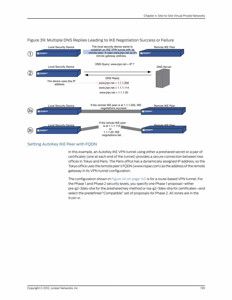
Figure 39: Multiple DNS Replies Leading to IKE Negotiation Success or Failure
The local security device wants toestablish an IKE VPN tunnel with its
remote peer. It uses www.jnpr.net as theremote gateway address.
Local Security Device
Local Security Device
Local Security Device
Local Security Device
Remote IKE Peer
Remote IKE Peer
Remote IKE Peer
DNS ServerDNS Query: www.jnpr.net = IP ?
DNS Reply:
www.jnpr.net = 1.1.1.202
www.jnpr.net = 1.1.1.114
www.jnpr.net = 1.1.1.20
If the remote IKE peer is at 1.1.1.202, IKEnegotiations succeed.
If the remote IKE peeris at 1.1.1.114
or1.1.1.20, IKE
negotiations fail.
The device uses this IPaddress.
Setting AutoKey IKE Peer with FQDN
In this example, an AutoKey IKE VPN tunnel using either a preshared secret or a pair of
certificates (one at each end of the tunnel) provides a secure connection between two
offices in Tokyo and Paris. The Paris office has a dynamically assigned IP address, so the
Tokyo office uses the remote peer’s FQDN (www.nspar.com) as the address of the remote
gateway in its VPN tunnel configuration.
The configuration shown in Figure 40 on page 140 is for a route-based VPN tunnel. For
the Phase 1 and Phase 2 security levels, you specify one Phase 1 proposal—either
pre-g2-3des-sha for the preshared key method or rsa-g2-3des-sha for certificates—and
select the predefined “Compatible” set of proposals for Phase 2. All zones are in the
trust-vr.
139Copyright © 2012, Juniper Networks, Inc.
Chapter 4: Site-to-Site Virtual Private Networks

Figure 40: AutoKey IKE Peer with FQDN
ParisTokyo
Topology of the zonesconfigured on the security
device in Tokyo
TrustZone
UntrustZone
Topology of the zonesconfigured on the security
device in Paris
TrustZone
UntrustZone
Tokyo
TokyoTrust Zone
ethernet1, 10.1.1.1/24
ParisTrust Zone
ethernet1, 10.2.2.1/24
VPN Tunnel
Internet
Paris
Outgoing InterfaceUntrust Zone
ethernet3, 1.1.1.1/24Gateway 1.1.1.250
Outgoing InterfaceUntrust Zone
ethernet3, IP and gatewayvia DHCP
www.nspar.com
Tunnel Interface: tunnel.1Remote Gateway: www.nspar.com
Tunnel Interface: tunnel.1Remote Gateway: 1.1.1.1
Setting up a route-based AutoKey IKE tunnel using either a preshared secret or certificates
involves the following steps:
1. Assign IP addresses to the physical interfaces bound to the security zones and to the
tunnel interface.
2. Define the remote gateway and key exchange mode, and specify either a preshared
secret or a certificate.
3. Configure the VPN tunnel, designate its outgoing interface in the Untrust zone, bind
it to the tunnel interface, and configure its proxy-ID.
4. Enter the IP addresses for the local and remote endpoints in the Trust and Untrust
address books.
5. Enter a default route to the external router in the trust-vr, a route to the destination
through the tunnel interface, and a null route to the destination. You assign a higher
metric (farther from zero) to the null route so that it becomes the next-choice route
to the destination. Then, if the state of the tunnel interface changes to “down” and
the route referencing that interface becomes inactive, the security device uses the
null route, which essentially drops any traffic sent to it, rather than the default route,
which forwards unencrypted traffic.
6. Set up policies for traffic to pass between each site.
In the following examples, the preshared key is h1p8A24nG5. It is assumed that both
participants already have RSA certificates and are using Entrust as the certificate authority
(CA). (For information about obtaining and loading certificates, see “Public Key
Cryptography” on page 35.)
WebUI (Tokyo)
1. Interfaces
Network > Interfaces > Edit (for ethernet1): Enter the following, then click Apply:
Copyright © 2012, Juniper Networks, Inc.140
Virtual Private Networks

Zone Name: TrustStatic IP: (select this option when present)IP Address/Netmask: 10.1.1.1/24
Select the following, then click OK:
Interface Mode: NAT
Network > Interfaces > Edit (for ethernet3): Enter the following, then click OK:
Zone Name: UntrustStatic IP: (select this option when present)IP Address/Netmask: 1.1.1.1
Network > Interfaces > New Tunnel IF: Enter the following, then click OK:
Tunnel Interface Name: tunnel.1Zone (VR): Untrust (trust-vr)Unnumbered: (select)Interface: ethernet3 (trust-vr)
2. Addresses
Policy > Policy Elements > Addresses > List > New: Enter the following, then clickOK:
Address Name: Trust_LANIP Address/Domain Name:IP/Netmask: (select), 10.1.1.0/24
Zone: Trust
Policy > Policy Elements > Addresses > List > New: Enter the following, then clickOK:
Address Name: Paris_OfficeIP Address/Domain Name:IP/Netmask: (select), 10.2.2.0/24
Zone: Untrust
3. VPN
VPNs > AutoKey Advanced > Gateway > New: Enter the following, then click OK:
Gateway Name: To_ParisSecurity Level: CustomRemote Gateway Type:Static IP Address: (select), IP Address/Hostname: www.nspar.com
Preshared Key
Preshared Key: h1p8A24nG5Outgoing Interface: ethernet3
> Advanced: Enter the following advanced settings, then click Return to return to the
basic Gateway configuration page:
Security Level: CustomPhase 1 Proposal (for Custom Security Level): pre-g2-3des-shaMode (Initiator): Main (ID Protection)
(or)
Certificates
Outgoing Interface: ethernet3
141Copyright © 2012, Juniper Networks, Inc.
Chapter 4: Site-to-Site Virtual Private Networks

> Advanced: Enter the following advanced settings, then click Return to return to the
basic Gateway configuration page:
Security Level: CustomPhase 1 Proposal (for Custom Security Level): rsa-g2-3des-shaPreferred certificate (optional)Peer CA: EntrustPeer Type: X509-SIG
VPNs > AutoKey IKE > New: Enter the following, then click OK:
VPNName: Tokyo_ParisSecurity Level: CompatibleRemote Gateway:Predefined: (select), To_Paris
> Advanced: Enter the following advanced settings, then click Return to return to the
basic AutoKey IKE configuration page:
Security Level: CompatibleBind to: Tunnel Interface, tunnel.1Proxy-ID: (select)Local IP / Netmask: 10.1.1.0/24Remote IP / Netmask: 10.2.2.0/24Service: ANY
4. Routes
Network > Routing > Routing Entries > trust-vr New: Enter the following, then click
OK:
Network Address/Netmask: 0.0.0.0/0Gateway: (select)Interface: ethernet3Gateway IP Address: 0.0.0.0
NOTE: The ISP provides the gateway IP address dynamically throughDHCP.
Network > Routing > Routing Entries > trust-vr New: Enter the following, then click
OK:
Network Address/Netmask: 10.2.2.0/24Gateway: (select)Interface: tunnel.1Gateway IP Address: 0.0.0.0
Network > Routing > Routing Entries > trust-vr New: Enter the following, then click
OK:
Network Address/Netmask: 10.2.2.0/24Gateway: (select)Interface: NullGateway IP Address: 0.0.0.0Metric: 10
5. Policies
Copyright © 2012, Juniper Networks, Inc.142
Virtual Private Networks

Policies > (From: Trust, To: Untrust) New: Enter the following, then click OK:
Name: To ParisSource Address: Trust_LANDestination Address: Paris_OfficeService: ANYAction: PermitPosition at Top: (select)
Policies > Policy (From: Untrust, To: Trust) > New Policy: Enter the following, then
click OK:
Name: From ParisSource Address: Paris_OfficeDestination Address: Trust_LANService: ANYAction: PermitPosition at Top: (select)
WebUI (Paris)
1. Host Name and Domain Name
Network > DNS: Enter the following, then click Apply:
Host Name: wwwDomain Name: nspar.com
2. Interfaces
Network > Interfaces > Edit (for ethernet1): Enter the following, then click Apply:
Zone Name: TrustStatic IP: (select this option when present)IP Address/Netmask: 10.2.2.1/24
Select the following, then click OK:
Interface Mode: NAT
Network > Interfaces > Edit (for ethernet3): Enter the following, then click OK:
Zone Name: UntrustObtain IP using DHCP: (select)
Network > Interfaces > New Tunnel IF: Enter the following, then click OK:
Tunnel Interface Name: tunnel.1Zone (VR): Untrust (trust-vr)Unnumbered: (select)Interface: ethernet3 (trust-vr)
3. Addresses
Policy > Policy Elements > Addresses > List > New: Enter the following, then clickOK:
Address Name: Trust_LANIP Address/Domain Name:IP/Netmask: (select), 10.2.2.0/24
Zone: Trust
Policy > Policy Elements > Addresses > List > New: Enter the following, then clickOK:
143Copyright © 2012, Juniper Networks, Inc.
Chapter 4: Site-to-Site Virtual Private Networks
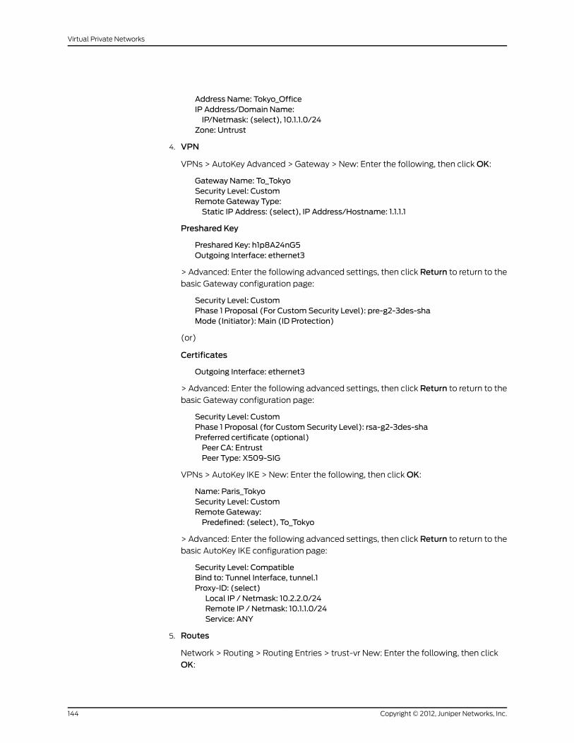
Address Name: Tokyo_OfficeIP Address/Domain Name:IP/Netmask: (select), 10.1.1.0/24
Zone: Untrust
4. VPN
VPNs > AutoKey Advanced > Gateway > New: Enter the following, then click OK:
Gateway Name: To_TokyoSecurity Level: CustomRemote Gateway Type:Static IP Address: (select), IP Address/Hostname: 1.1.1.1
Preshared Key
Preshared Key: h1p8A24nG5Outgoing Interface: ethernet3
> Advanced: Enter the following advanced settings, then click Return to return to the
basic Gateway configuration page:
Security Level: CustomPhase 1 Proposal (For Custom Security Level): pre-g2-3des-shaMode (Initiator): Main (ID Protection)
(or)
Certificates
Outgoing Interface: ethernet3
> Advanced: Enter the following advanced settings, then click Return to return to the
basic Gateway configuration page:
Security Level: CustomPhase 1 Proposal (for Custom Security Level): rsa-g2-3des-shaPreferred certificate (optional)Peer CA: EntrustPeer Type: X509-SIG
VPNs > AutoKey IKE > New: Enter the following, then click OK:
Name: Paris_TokyoSecurity Level: CustomRemote Gateway:Predefined: (select), To_Tokyo
> Advanced: Enter the following advanced settings, then click Return to return to the
basic AutoKey IKE configuration page:
Security Level: CompatibleBind to: Tunnel Interface, tunnel.1Proxy-ID: (select)Local IP / Netmask: 10.2.2.0/24Remote IP / Netmask: 10.1.1.0/24Service: ANY
5. Routes
Network > Routing > Routing Entries > trust-vr New: Enter the following, then click
OK:
Copyright © 2012, Juniper Networks, Inc.144
Virtual Private Networks

Network Address/Netmask: 0.0.0.0/0Gateway: (select)Interface: ethernet3Gateway IP Address: 2.2.2.250
Network > Routing > Routing Entries > trust-vr New: Enter the following, then click
OK:
Network Address/Netmask: 10.1.1.0/24Gateway: (select)Interface: tunnel.1Gateway IP Address: 0.0.0.0
Network > Routing > Routing Entries > trust-vr New: Enter the following, then click
OK:
Network Address/Netmask: 10.1.1.0/24Gateway: (select)Interface: NullGateway IP Address: 0.0.0.0Metric: 10
6. Policies
Policies > (From: Trust, To: Untrust) New: Enter the following, then click OK:
Name: To TokyoSource Address: Trust_LANDestination Address: Tokyo_OfficeService: ANYAction: PermitPosition at Top: (select)
Policies > (From: Untrust, To: Trust) New: Enter the following, then click OK:
Name: From TokyoSource Address: Tokyo_OfficeDestination Address: Trust_LANService: ANYAction: PermitPosition at Top: (select)
CLI (Tokyo)
1. Interfaces
set interface ethernet1 zone trustset interface ethernet1 ip 10.1.1.1/24set interface ethernet1 natset interface ethernet3 zone untrustset interface ethernet3 ip 1.1.1.1/24set interface tunnel.1 zone untrustset interface tunnel.1 ip unnumbered interface ethernet3
2. Addresses
set address trust Trust_LAN 10.1.1.0/24set address untrust paris_office 10.2.2.0/24
3. VPN
145Copyright © 2012, Juniper Networks, Inc.
Chapter 4: Site-to-Site Virtual Private Networks

Preshared Key
set ike gateway to_paris address www.nspar.commain outgoing-interface ethernet3preshare h1p8A24nG5 proposal pre-g2-3des-shaset vpn tokyo_paris gateway to_paris sec-level compatibleset vpn tokyo_paris bind interface tunnel.1set vpn tokyo_paris proxy-id local-ip 10.1.1.0/24 remote-ip 10.2.2.0/24 any
(or)
Certificate
Certificateset ike gateway to_paris address www.nspar.commain outgoing-interface ethernet3proposal rsa-g2-3des-shaset ike gateway to_paris cert peer-ca 1set ike gateway to_paris cert peer-cert-type x509-sigset vpn tokyo_paris gateway to_paris sec-level compatibleset vpn tokyo_paris bind interface tunnel.1set vpn tokyo_paris proxy-id local-ip 10.1.1.0/24 remote-ip 10.2.2.0/24 any
NOTE: The number 1 is the CA ID number. To discover the CA’s ID number,use the following command: get ike ca.
4. Routes
set vrouter trust-vr route 0.0.0.0/0 interface ethernet3 gateway 1.1.1.250set vrouter trust-vr route 10.2.2.0/24 interface tunnel.1set vrouter trust-vr route 10.2.2.0/24 interface null metric 10
5. Policies
set policy top name “ToParis” from trust to untrust Trust_LANparis_office any permitset policy top name “From Paris” from untrust to trust paris_office Trust_LAN anypermitsave
CLI (Paris)
1. Host Name and Domain Name
set hostnamewwwset domain nspar.com
2. Interfaces
set interface ethernet1 zone trustset interface ethernet1 ip 10.2.2.1/24set interface ethernet1 natset interface ethernet3 zone untrustset interface ethernet3 ip dhcp-client enableset interface tunnel.1 zone untrustset interface tunnel.1 ip unnumbered interface ethernet3
3. Addresses
set address trust Trust_LAN 10.2.2.0/24set address untrust tokyo_office 10.1.1.0/24
Copyright © 2012, Juniper Networks, Inc.146
Virtual Private Networks

4. VPN
Preshared Key
set ike gateway to_tokyo address 1.1.1.1 main outgoing-interface ethernet3 preshareh1p8A24nG5 proposal pre-g2-3des-shaset vpn paris_tokyo gateway to_tokyo sec-level compatibleset vpn paris_tokyo bind interface tunnel.1set vpn paris_tokyo proxy-id local-ip 10.2.2.0/24 remote-ip 10.1.1.0/24 any
(or)
Certificate
set ike gateway to_tokyo address 1.1.1.1 main outgoing-interface ethernet3 proposalrsa-g2-3des-shaset ike gateway to_tokyo cert peer-ca 1set ike gateway to_tokyo cert peer-cert-type x509-sigset vpn paris_tokyo gateway to_tokyo sec-level compatibleset vpn paris_tokyo bind interface tunnel.1set vpn paris_tokyo proxy-id local-ip 10.2.2.0/24 remote-ip 10.1.1.0/24 any
5. Routes
set vrouter trust-vr route 0.0.0.0/0 interface ethernet3 gateway 2.2.2.250set vrouter trust-vr route 10.1.1.0/24 interface tunnel.1set vrouter trust-vr route 10.1.1.0/24 interface null metric 10
6. Policies
set policy top name “To Tokyo” from trust to untrust Trust_LAN tokyo_office anypermitset policy top name “From Tokyo” from untrust to trust tokyo_office Trust_LAN anypermitsave
VPN Sites with Overlapping Addresses
Because the range of private IP addresses is relatively small, there is a good chance that
the addresses of protected networks of two VPN peers overlap. For bidirectional VPN
traffic between two end entities with overlapping addresses, the security devices at both
ends of the tunnel must apply Source Network Address Translation (NAT-src) and
Destination Network Address Translation (NAT-dst) to the VPN traffic passing between
them.
NOTE: An overlapping address space is when the IP address range in twonetworks are partially or completely the same.
For NAT-src, the interfaces at both ends of the tunnel must have IP addresses in mutually
unique subnets, with a dynamic IP (DIP) pool in each of those subnets. The policies
regulating outbound VPN traffic can then apply NAT-src using DIP pool addresses to
translate original source addresses to those in a neutral address space.
147Copyright © 2012, Juniper Networks, Inc.
Chapter 4: Site-to-Site Virtual Private Networks
NOTE: The range of addresses in a DIP pool must be in the same subnet asthe tunnel interface, but the pool must not include the interface IP addressor any MIP or VIP addresses that might also be in that subnet. For securityzone interfaces, you can also define an extended IP address and anaccompanying DIP pool in a different subnet from that of the interface IPaddress. For more information, see Using DIP in a Different Subnet.
To provide NAT-dst on inbound VPN traffic, there are two options:
• Policy-based NAT-dst: A policy can apply NAT-dst to translate inbound VPN traffic to
an address that is either in the same subnet as the tunnel interface—but not in the
same range as the local DIP pool used for outbound VPN traffic—or to an address in
another subnet to which the security device has an entry in its route table. (For
information about routing considerations when configuring NAT-dst, see Routing for
NAT-DST.)
• Mapped IP (MIP): A policy can reference a MIP as the destination address. The MIP
uses an address in the same subnet as the tunnel interface—but not in the same range
as the local DIP pool used for outbound VPN traffic. (For information about MIPs, see
Mapped IP Addresses.)
VPN traffic between sites with overlapping addresses requires address translation in
both directions. Because the source address on outbound traffic cannot be the same as
the destination address on inbound traffic—the NAT-dst address or MIP cannot be in the
DIP pool—the addresses referenced in the inbound and outbound policies cannot be
symmetrical.
When you want the security device to perform source and destination address translation
on bidirectional VPN traffic through the same tunnel, you have two choices:
• You can define a proxy ID for a policy-based VPN configuration. When you specifically
reference a VPN tunnel in a policy, the security device derives a proxy ID from the
components in the policy that references that tunnel. The security device derives the
proxy ID when you first create the policy, and each time the device reboots thereafter.
However, if you manually define a proxy ID for a VPN tunnel that is referenced in a
policy, the security device applies the user-defined proxy ID, not the proxy ID derived
from the policy.
NOTE: Aproxy ID isakindofagreementbetween IKEpeers topermit trafficthrough a tunnel if the traffic matches a specified tuple of local address,remote address, and service.
• You can use a route-based VPN tunnel configuration, which must have a user-defined
proxy ID. With a route-based VPN tunnel configuration, you do not specifically reference
a VPN tunnel in a policy. Instead, the policy controls access (permit or deny) to a
particular destination. The route to that destination points to a tunnel interface that
in turn is bound to a VPN tunnel. Because the VPN tunnel is not directly associated
with a policy from which it can derive a proxy ID from the source address, destination
Copyright © 2012, Juniper Networks, Inc.148
Virtual Private Networks

address, and service, you must manually define a proxy ID for it. (Note that a
route-based VPN configuration also allows you to create multiple policies that make
use of a single VPN tunnel; that is, a single Phase 2 SA.)
Consider the addresses in Figure 41 on page 149, which illustrates a VPN tunnel between
two sites with overlapping address spaces.
Figure 41: Overlapping Addresses at Peer Sites
10.10.1.2 – 10.10.1.2 DIP10.10.1.5 (to 10.1.1.5) MIP
MIP 10.20.2.5 (to 10.1.1.5)DIP 10.20.2.2 – 10.20.2.2
Internal AddressSpace
10.1.1.0/24
Internal AddressSpace
10.1.1.0/24tunnel.110.10.1.1/24
tunnel.210.20.2.1/24
Device-A Device-BVPN Tunnel
Addresses in Policies
If the security devices in Figure 41 on page 149 derive proxy IDs from the policies, as they
do in policy-based VPN configurations, then the inbound and outbound policies produce
the following proxy IDs:
Device BDevice A
ServiceRemoteLocalServiceRemoteLocal
Any10.10.1.2/3210.20.2.5/32InboundAny10.20.2.5/3210.10.1.2/32Outbound
Any10.10.1.5/3210.20.2.2/32OutboundAny10.20.2.2/3210.10.1.5/32Inbound
As shown in the table, there are two proxy IDs: one for outbound VPN traffic and another
for inbound. When Device A first sends traffic from 10.10.1.2/32 to 10.20.2.5/32, the two
peers perform IKE negotiations and produce Phase 1 and Phase 2 security associations
(SAs). The Phase 2 SA results in the above outbound proxy ID for Device A, and the
inbound proxy ID for Device B.
If Device B then sends traffic to Device A, the policy lookup for traffic from 10.20.2.2/32
to 10.10.1.5/32 indicates that there is no active Phase 2 SA for such a proxy ID. Therefore,
the two peers use the existing Phase 1 SA (assuming that its lifetime has not yet expired)
to negotiate a different Phase 2 SA. The resulting proxy IDs are shown above as the
inbound proxy ID for Device A and the outbound proxy ID for Device B. There are two
Phase 2 SAs—two VPN tunnels—because the addresses are asymmetrical and require
different proxy IDs.
To create just one tunnel for bidirectional VPN traffic, you can define the following proxy
IDs with addresses whose scope includes both the translated source and destination
addresses at each end of the tunnel:
Device BDevice A
ServiceRemoteLocalServiceRemoteLocal
149Copyright © 2012, Juniper Networks, Inc.
Chapter 4: Site-to-Site Virtual Private Networks
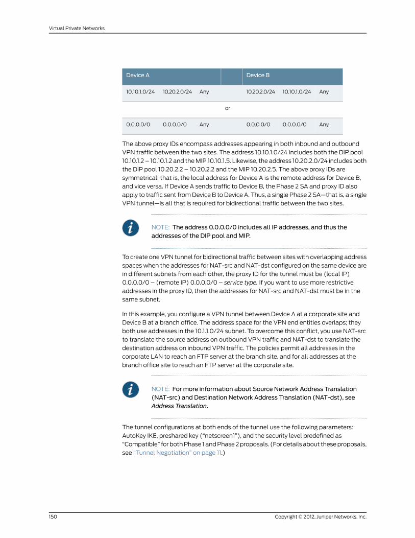
Device BDevice A
Any10.10.1.0/2410.20.2.0/24Any10.20.2.0/2410.10.1.0/24
or
Any0.0.0.0/00.0.0.0/0Any0.0.0.0/00.0.0.0/0
The above proxy IDs encompass addresses appearing in both inbound and outbound
VPN traffic between the two sites. The address 10.10.1.0/24 includes both the DIP pool
10.10.1.2 – 10.10.1.2 and the MIP 10.10.1.5. Likewise, the address 10.20.2.0/24 includes both
the DIP pool 10.20.2.2 – 10.20.2.2 and the MIP 10.20.2.5. The above proxy IDs are
symmetrical; that is, the local address for Device A is the remote address for Device B,
and vice versa. If Device A sends traffic to Device B, the Phase 2 SA and proxy ID also
apply to traffic sent from Device B to Device A. Thus, a single Phase 2 SA—that is, a single
VPN tunnel—is all that is required for bidirectional traffic between the two sites.
NOTE: The address 0.0.0.0/0 includes all IP addresses, and thus theaddresses of the DIP pool andMIP.
To create one VPN tunnel for bidirectional traffic between sites with overlapping address
spaces when the addresses for NAT-src and NAT-dst configured on the same device are
in different subnets from each other, the proxy ID for the tunnel must be (local IP)
0.0.0.0/0 – (remote IP) 0.0.0.0/0 – service type. If you want to use more restrictive
addresses in the proxy ID, then the addresses for NAT-src and NAT-dst must be in the
same subnet.
In this example, you configure a VPN tunnel between Device A at a corporate site and
Device B at a branch office. The address space for the VPN end entities overlaps; they
both use addresses in the 10.1.1.0/24 subnet. To overcome this conflict, you use NAT-src
to translate the source address on outbound VPN traffic and NAT-dst to translate the
destination address on inbound VPN traffic. The policies permit all addresses in the
corporate LAN to reach an FTP server at the branch site, and for all addresses at the
branch office site to reach an FTP server at the corporate site.
NOTE: For more information about Source Network Address Translation(NAT-src) and Destination Network Address Translation (NAT-dst), seeAddress Translation.
The tunnel configurations at both ends of the tunnel use the following parameters:
AutoKey IKE, preshared key (“netscreen1”), and the security level predefined as
“Compatible” for both Phase 1 and Phase 2 proposals. (For details about these proposals,
see “Tunnel Negotiation” on page 11.)
Copyright © 2012, Juniper Networks, Inc.150
Virtual Private Networks

The outgoing interface on Device A at the corporate site is ethernet3, which has IP address
1.1.1.1/24 and is bound to the Untrust zone. Device B at the branch office uses this address
as its remote IKE gateway.
The outgoing interface on Device B at the branch office is ethernet3, which has IP address
2.2.2.2/24 and is bound to the Untrust zone. Device A at the corporate site uses this
address as its remote IKE gateway.
The Trust zone interface on both security devices is ethernet1 and has IP address 10.1.1.1/24.
All zones on both security devices are in the trust-vr routing domain.
Figure 42: Tunnel Interface with NAT-Src and NAT-Dst
AB
Topology of the zonesconfigured on Device-A at the
branch office.
Trust Zone Untrust Zone
A B
Trust ZoneUntrust Zone
Topology of the zonesconfigured on Device-B at
the branch1 office.
Users at network A can access server B. Users at network B can access server A.All traffic flows through the VPN tunnel between the two sites.
Gateway1.1.1.250
Gateway2.2.2.250
serverB10.1.1.5
network A10.1.1.0/24
serverA10.1.1.5
DIP 5 10.10.1.2 – 10.10.1.2NAT-Dst 10.10.1.5 –> 10.1.1.5
Tunnel.1 10.10.1.1/24
Device-A
DIP 6 10.20.1.2 – 10.20.1.2NAT-Dst 10.20.1.5 –> 10.1.1.5
Tunnel.1 10.20.1.1/24
Device-B
Device-A Device-B
network B10.1.1.0/24
network B
serverB
VPN Tunnel“vpn1”
Internet
network A
server A
WebUI (Device A)
1. Interfaces
Network > Interfaces > Edit (for ethernet1): Enter the following, then click Apply:
Zone Name: TrustStatic IP: (select this option when present)IP Address/Netmask: 10.1.1.1/24
Select the following, then click OK:
Interface Mode: NAT
Network > Interfaces > Edit (for ethernet3): Enter the following, then click OK:
Zone Name: UntrustStatic IP: (select this option when present)IP Address/Netmask: 1.1.1.1/24
151Copyright © 2012, Juniper Networks, Inc.
Chapter 4: Site-to-Site Virtual Private Networks

Network > Interfaces > New Tunnel IF: Enter the following, then click OK:
Tunnel Interface Name: tunnel.1Zone (VR): Untrust (trust-vr)Fixed IP: (select)IP Address / Netmask: 10.10.1.1/24
2. DIP
Network > Interfaces > Edit (for tunnel.1) > DIP > New: Enter the following, then click
OK:
ID: 5IP Address Range: (select), 10.10.1.2 ~ 10.10.1.2Port Translation: (select)
In the same subnet as the interface IP or its secondary IPs: (select)
3. Addresses
Policy > Policy Elements > Addresses > List > New: Enter the following, then clickOK:
Address Name: corpIP Address/Domain Name:IP/Netmask: (select), 10.1.1.0/24
Zone: Trust
Policy > Policy Elements > Addresses > List > New: Enter the following, then clickOK:
Address Name: virtualAIP Address/Domain Name:IP/Netmask: (select), 10.10.1.5/32
Zone: Trust
Policy > Policy Elements > Addresses > List > New: Enter the following, then clickOK:
Address Name: branch1IP Address/Domain Name:IP/Netmask: (select), 10.20.1.2/32
Zone: Untrust
Policy > Policy Elements > Addresses > List > New: Enter the following, then clickOK:
Address Name: serverBIP Address/Domain Name:IP/Netmask: (select), 10.20.1.5/32
Zone: Untrust
4. VPN
VPNs > AutoKey IKE > New: Enter the following, then click OK:
VPNName: vpn1Security Level: CompatibleRemote Gateway: Create a Simple Gateway: (select)Gateway Name: branch1Type: Static IP: (select), Address/Hostname: 2.2.2.2Preshared Key: netscreen1Security Level: CompatibleOutgoing Interface: ethernet3
Copyright © 2012, Juniper Networks, Inc.152
Virtual Private Networks

NOTE: The outgoing interface does not have to be in the same zone towhich the tunnel interface is bound, although in this case they are in thesame zone.
> Advanced: Enter the following advanced settings, then click Return to return to the
basic AutoKey IKE configuration page:
Bind to: Tunnel Interface, tunnel.1Proxy-ID: (select)Local IP / Netmask: 10.10.1.0/24Remote IP / Netmask: 10.20.1.0/24Service: ANY
5. Routes
Network > Routing > Routing Entries > trust-vr New: Enter the following, then click
OK:
Network Address/Netmask: 0.0.0.0/0Gateway: (select)Interface: ethernet3Gateway IP Address: 1.1.1.250
Network > Routing > Routing Entries > trust-vr New: Enter the following, then click
OK:
Network Address/Netmask: 10.20.1.0/24Gateway: (select)Interface: tunnel.1Gateway IP Address: 0.0.0.0
Network > Routing > Routing Entries > trust-vr New: Enter the following, then click
OK:
Network Address/Netmask: 10.20.1.0/24Gateway: (select)Interface: NullGateway IP Address: 0.0.0.0Metric: 10
6. Policies
Policies > (From: Trust, To: Untrust) New: Enter the following, then click OK:
Source Address:Address Book Entry: (select), corp
Destination Address:Address Book Entry: (select), serverB
Service: FTPAction: PermitPosition at Top: (select)
> Advanced: Enter the following advanced settings, then click Return to return to the
basic Policy configuration page:
153Copyright © 2012, Juniper Networks, Inc.
Chapter 4: Site-to-Site Virtual Private Networks

NAT:Source Translation: (select)DIP On: 5 (10.10.1.2–10.10.1.2)/X-late
Policies > (From: Untrust, To: Trust) New: Enter the following, then click OK:
Source Address:Address Book Entry: (select), branch1
Destination Address:Address Book Entry: (select), virtualA
Service: FTPAction: PermitPosition at Top: (select)
> Advanced: Enter the following advanced settings, then click Return to return to the
basic Policy configuration page:
NAT:Destination Translation: (select)Translate to IP: (select), 10.1.1.5Map to Port: (clear)
WebUI (Device B)
1. Interfaces
Network > Interfaces > Edit (for ethernet1): Enter the following, then click Apply:
Zone Name: TrustStatic IP: (select this option when present)IP Address/Netmask: 10.1.1.1/24
Select the following, then click OK:
Interface Mode: NAT
Network > Interfaces > Edit (for ethernet3): Enter the following, then click OK:
Zone Name: UntrustStatic IP: (select this option when present)IP Address/Netmask: 2.2.2.2/24
Network > Interfaces > New Tunnel IF: Enter the following, then click OK:
Tunnel Interface Name: tunnel.1Zone (VR): Untrust (trust-vr)Fixed IP: (select)IP Address / Netmask: 10.20.1.1/24
2. DIP
Network > Interfaces > Edit (for tunnel.1) > DIP > New: Enter the following, then click
OK:
ID: 6IP Address Range: (select), 10.20.1.2 ~ 10.20.1.2Port Translation: (select)
In the same subnet as the interface IP or its secondary IPs: (select)
3. Addresses
Copyright © 2012, Juniper Networks, Inc.154
Virtual Private Networks

Policy > Policy Elements > Addresses > List > New: Enter the following, then clickOK:
Address Name: branch1IP Address/Domain Name:IP/Netmask: (select), 10.1.1.0/24
Zone: Trust
Policy > Policy Elements > Addresses > List > New: Enter the following, then clickOK:
Address Name: virtualBIP Address/Domain Name:IP/Netmask: (select), 10.20.1.5/32
Zone: Trust
Policy > Policy Elements > Addresses > List > New: Enter the following, then clickOK:
Address Name: corpIP Address/Domain Name:IP/Netmask: (select), 10.10.1.2/32
Zone: Untrust
Policy > Policy Elements > Addresses > List > New: Enter the following, then clickOK:
Address Name: serverAIP Address/Domain Name:IP/Netmask: (select), 10.10.1.5/32
Zone: Untrust
4. VPN
VPNs > AutoKey IKE > New: Enter the following, then click OK:
VPNName: vpn1Security Level: CompatibleRemote Gateway: Create a Simple Gateway: (select)Gateway Name: corpType: Static IP: (select), Address/Hostname: 1.1.1.1Preshared Key: netscreen1Security Level: CompatibleOutgoing Interface: ethernet3
> Advanced: Enter the following advanced settings, then click Return to return to the
basic AutoKey IKE configuration page:
Bind to: Tunnel Interface, tunnel.1Proxy-ID: (select)Local IP / Netmask: 10.20.1.0/24Remote IP / Netmask: 10.10.1.0/24Service: ANY
NOTE: The outgoing interface does not have to be in the same zone towhich the tunnel interface is bound, although in this case they are in thesame zone.
5. Routes
Network > Routing > Routing Entries > trust-vr New: Enter the following, then click
OK:
155Copyright © 2012, Juniper Networks, Inc.
Chapter 4: Site-to-Site Virtual Private Networks

Network Address/Netmask: 0.0.0.0/0Gateway: (select)Interface: ethernet3Gateway IP Address: 2.2.2.250
Network > Routing > Routing Entries > trust-vr New: Enter the following, then click
OK:
Network Address/Netmask: 10.10.1.0/24Gateway: (select)Interface: tunnel.1Gateway IP Address: 0.0.0.0
Network > Routing > Routing Entries > trust-vr New: Enter the following, then click
OK:
Network Address/Netmask: 10.10.1.0/24Gateway: (select)Interface: NullGateway IP Address: 0.0.0.0Metric: 10
6. Policies
Policies > (From: Trust, To: Untrust) New: Enter the following, then click OK:
Source Address:Address Book Entry: (select), corp
Destination Address:Address Book Entry: (select), serverA
Service: FTPAction: PermitPosition at Top: (select)
> Advanced: Enter the following advanced settings, then click Return to return to the
basic Policy configuration page:
NAT:Source Translation: (select)DIP on: 6 (10.20.1.2–10.20.1.2)/X-late
Policies > (From: Untrust, To: Trust) New: Enter the following, then click OK:
Source Address:Address Book Entry: (select), corp
Destination Address:Address Book Entry: (select), virtualB
Service: FTPAction: PermitPosition at Top: (select)
> Advanced: Enter the following advanced settings, then click Return to return to the
basic Policy configuration page:
NAT:Destination Translation: (select)Translate to IP: 10.1.1.5Map to Port: (clear)
Copyright © 2012, Juniper Networks, Inc.156
Virtual Private Networks
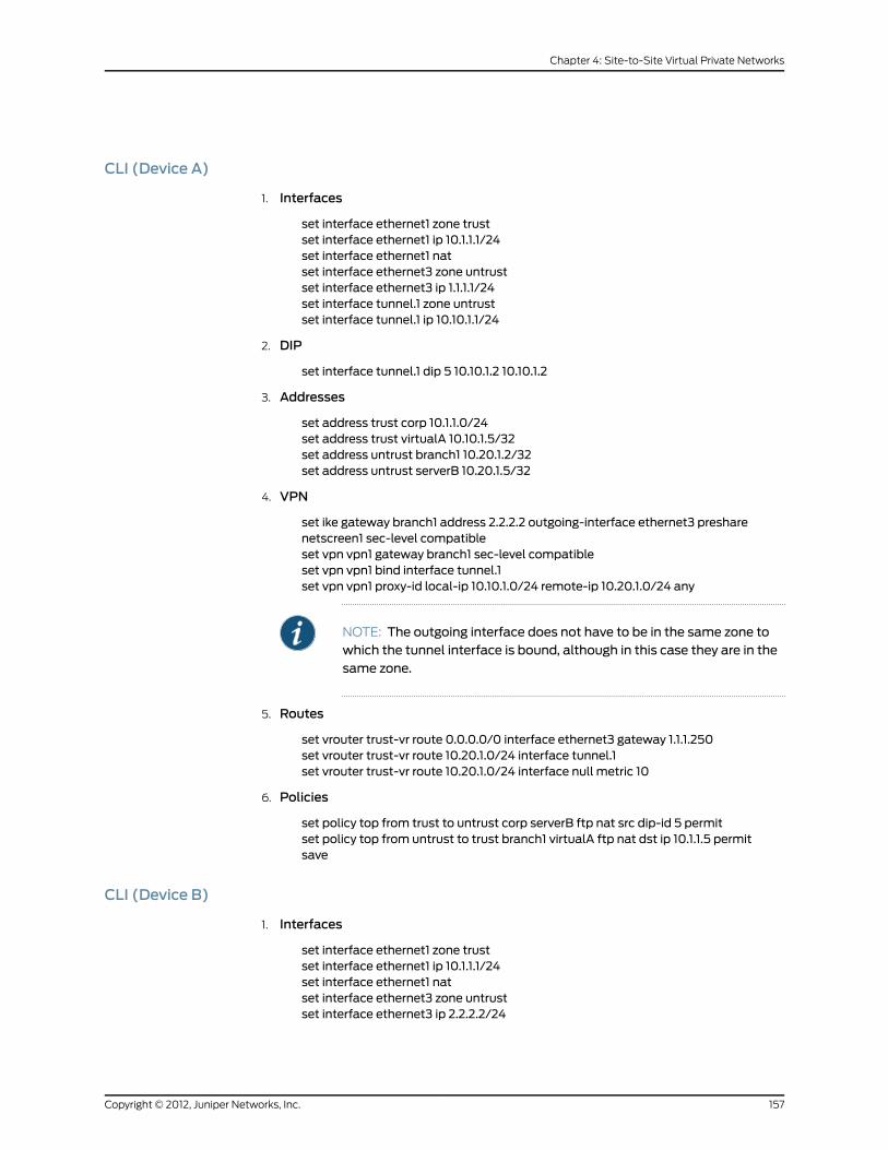
CLI (Device A)
1. Interfaces
set interface ethernet1 zone trustset interface ethernet1 ip 10.1.1.1/24set interface ethernet1 natset interface ethernet3 zone untrustset interface ethernet3 ip 1.1.1.1/24set interface tunnel.1 zone untrustset interface tunnel.1 ip 10.10.1.1/24
2. DIP
set interface tunnel.1 dip 5 10.10.1.2 10.10.1.2
3. Addresses
set address trust corp 10.1.1.0/24set address trust virtualA 10.10.1.5/32set address untrust branch1 10.20.1.2/32set address untrust serverB 10.20.1.5/32
4. VPN
set ike gateway branch1 address 2.2.2.2 outgoing-interface ethernet3 presharenetscreen1 sec-level compatibleset vpn vpn1 gateway branch1 sec-level compatibleset vpn vpn1 bind interface tunnel.1set vpn vpn1 proxy-id local-ip 10.10.1.0/24 remote-ip 10.20.1.0/24 any
NOTE: The outgoing interface does not have to be in the same zone towhich the tunnel interface is bound, although in this case they are in thesame zone.
5. Routes
set vrouter trust-vr route 0.0.0.0/0 interface ethernet3 gateway 1.1.1.250set vrouter trust-vr route 10.20.1.0/24 interface tunnel.1set vrouter trust-vr route 10.20.1.0/24 interface null metric 10
6. Policies
set policy top from trust to untrust corp serverB ftp nat src dip-id 5 permitset policy top from untrust to trust branch1 virtualA ftp nat dst ip 10.1.1.5 permitsave
CLI (Device B)
1. Interfaces
set interface ethernet1 zone trustset interface ethernet1 ip 10.1.1.1/24set interface ethernet1 natset interface ethernet3 zone untrustset interface ethernet3 ip 2.2.2.2/24
157Copyright © 2012, Juniper Networks, Inc.
Chapter 4: Site-to-Site Virtual Private Networks
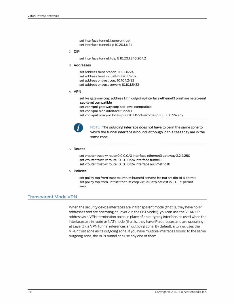
set interface tunnel.1 zone untrustset interface tunnel.1 ip 10.20.1.1/24
2. DIP
set interface tunnel.1 dip 6 10.20.1.2 10.20.1.2
3. Addresses
set address trust branch1 10.1.1.0/24set address trust virtualB 10.20.1.5/32set address untrust corp 10.10.1.2/32set address untrust serverA 10.10.1.5/32
4. VPN
set ike gateway corp address 1.1.1.1 outgoing-interface ethernet3 preshare netscreen1sec-level compatibleset vpn vpn1 gateway corp sec-level compatibleset vpn vpn1 bind interface tunnel.1set vpn vpn1 proxy-id local-ip 10.20.1.0/24 remote-ip 10.10.1.0/24 any
NOTE: The outgoing interface does not have to be in the same zone towhich the tunnel interface is bound, although in this case they are in thesame zone.
5. Routes
set vrouter trust-vr route 0.0.0.0/0 interface ethernet3 gateway 2.2.2.250set vrouter trust-vr route 10.10.1.0/24 interface tunnel.1set vrouter trust-vr route 10.10.1.0/24 interface null metric 10
6. Policies
set policy top from trust to untrust branch1 serverA ftp nat src dip-id 6 permitset policy top from untrust to trust corp virtualB ftp nat dst ip 10.1.1.5 permitsave
Transparent Mode VPN
When the security device interfaces are in transparent mode (that is, they have no IP
addresses and are operating at Layer 2 in the OSI Model), you can use the VLAN1 IP
address as a VPN termination point. In place of an outgoing interface, as used when the
interfaces are in route or NAT mode (that is, they have IP addresses and are operating
at Layer 3), a VPN tunnel references an outgoing zone. By default, a tunnel uses the
V1-Untrust zone as its outgoing zone. If you have multiple interfaces bound to the same
outgoing zone, the VPN tunnel can use any one of them.
Copyright © 2012, Juniper Networks, Inc.158
Virtual Private Networks

NOTE: The OSI Model is a networking industry standardmodel of networkprotocolarchitecture.TheOSIModel consistsof seven layers, inwhichLayer2is the Data-Link Layer and Layer 3 is the Network Layer.
At the time of this release, a security device whose interfaces are intransparent mode supports only policy-based VPNs. For more informationabout transparent mode, see Transparent Mode.
It isnotnecessary that the interfacesofbothsecuritydevicesbe in transparentmode. The interfaces of the device at one end of the tunnel can be intransparentmodeand thoseof theother device canbe in routeorNATmode.
In this example, you set up a policy-based AutoKey IKE VPN tunnel between two security
devices with interfaces operating in transparent mode.
NOTE: It is not necessary that the interfaces of both security devices be intransparent mode. The interfaces of the device at one end of the tunnel canbe in transparent mode and those of the other device can be in route or NATmode.
The key elements of the configuration for the security devices at both ends of the tunnel
are as follows:
Device BDevice AConfiguration Elements
Interface: ethernet1, 0.0.0.0/0(enable management for the local admin)
Interface: ethernet1, 0.0.0.0/0(enable management for the local admin)
V1-Trust Zone
Interface: ethernet3, 0.0.0.0/0Interface: ethernet3, 0.0.0.0/0V1-Untrust Zone
IP Address: 2.2.2.2/24Manage IP: 2.2.2.3
IP Address: 1.1.1.1/24Manage IP: 1.1.1.2
Note: You can separate administrative from VPNtraffic by using the Manage IP address to receiveadministrative traffic and the VLAN1 address toterminate VPN traffic.
VLAN1 Interface
local_lan: 2.2.2.0/24 in V1-Trustpeer_lan: 1.1.1.0/24 in V1-Untrust
local_lan: 1.1.1.0/24 in V1-Trustpeer_lan: 2.2.2.0/24 in V1-Untrust
Addresses
gw1, 1.1.1.1, preshared key h1p8A24nG5,security: compatible
gw1, 2.2.2.2, preshared key h1p8A24nG5,security: compatible
IKE Gateway
security: compatiblesecurity: compatibleVPN tunnel
local_lan -> peer_lan, any service, vpn1peer_lan -> local_lan, any service, vpn1
local_lan -> peer_lan, any service, vpn1peer_lan -> local_lan, any service, vpn1
Policies
159Copyright © 2012, Juniper Networks, Inc.
Chapter 4: Site-to-Site Virtual Private Networks

Device BDevice AConfiguration Elements
IP Address: 2.2.2.250IP Address: 1.1.1.250External Router
0.0.0.0/0, use VLAN1 interfaceto gateway 2.2.2.250
0.0.0.0/0, use VLAN1 interfaceto gateway 1.1.1.250
Route
Configuring a policy-based AutoKey IKE tunnel for a security device whose interfaces are
in transparent mode involves the following steps:
1. Remove any IP addresses from the physical interfaces, and bind them to the Layer 2
security zones.
2. Assign an IP address and Manage IP address to the VLAN1 interface.
3. Enter the IP addresses for the local and remote endpoints in the address books for
the V1-Trust and V1-Untrust zones.
4. Configure the VPN tunnel and designate its outgoing zone as the V1-Untrust zone.
5. Enter a default route to the external router in the trust-vr.
6. Set up policies for VPN traffic to pass between each site.
WebUI (Device A)
1. Interfaces
NOTE: Moving the VLAN1 IP address to a different subnet causes thesecuritydevice todeleteany routes involving thepreviousVLAN1 interface.When configuring a security device through theWebUI, your workstationmust reach the first VLAN1 address and thenbe in the same subnet as thenew address. After changing the VLAN1 address, youmust then changethe IP address of your workstation so that it is in the same subnet as thenew VLAN1 address. Youmight also have to relocate your workstation toa subnet physically adjacent to the security device.
Network > Interfaces > Edit (for the VLAN1 interface): Enter the following, then click
OK:
IP Address/Netmask: 1.1.1.1/24Manage IP: 1.1.1.2Management Services: WebUI, Telnet, Ping
Copyright © 2012, Juniper Networks, Inc.160
Virtual Private Networks
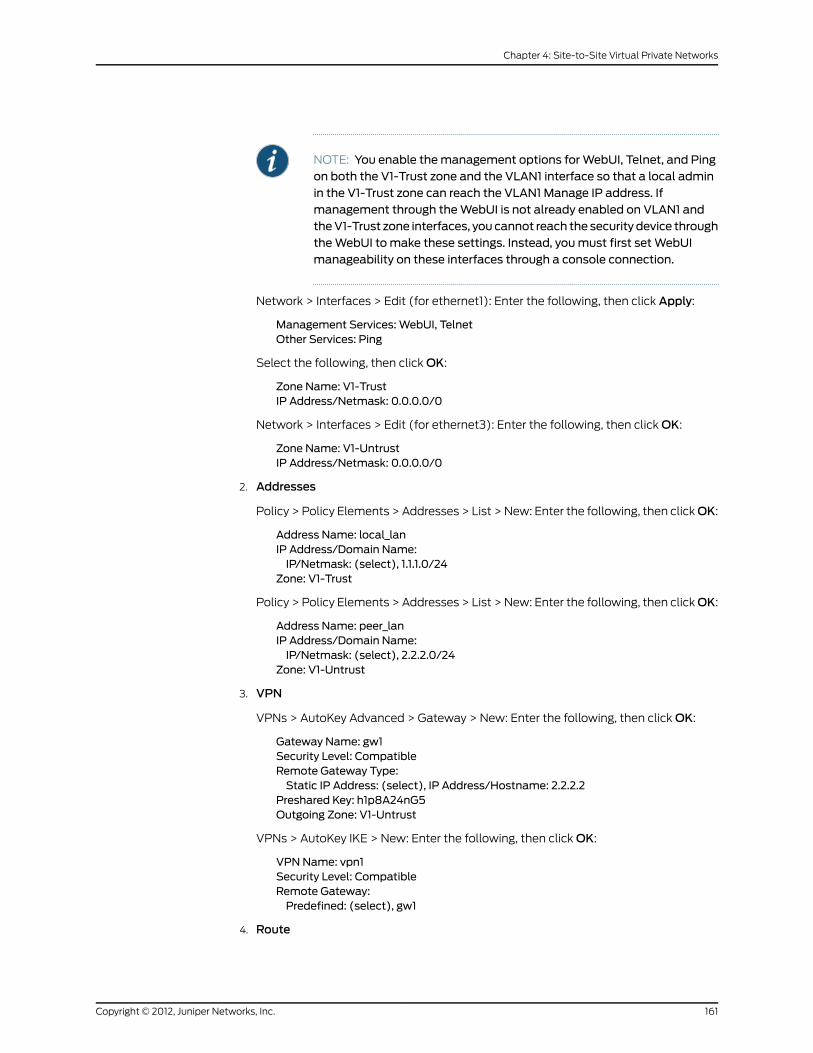
NOTE: You enable themanagement options forWebUI, Telnet, and Pingon both the V1-Trust zone and the VLAN1 interface so that a local adminin the V1-Trust zone can reach the VLAN1 Manage IP address. Ifmanagement through theWebUI is not already enabled on VLAN1 andtheV1-Trust zone interfaces, you cannot reach the security device throughtheWebUI tomake these settings. Instead, youmust first setWebUImanageability on these interfaces through a console connection.
Network > Interfaces > Edit (for ethernet1): Enter the following, then click Apply:
Management Services: WebUI, TelnetOther Services: Ping
Select the following, then click OK:
Zone Name: V1-TrustIP Address/Netmask: 0.0.0.0/0
Network > Interfaces > Edit (for ethernet3): Enter the following, then click OK:
Zone Name: V1-UntrustIP Address/Netmask: 0.0.0.0/0
2. Addresses
Policy > Policy Elements > Addresses > List > New: Enter the following, then clickOK:
Address Name: local_lanIP Address/Domain Name:IP/Netmask: (select), 1.1.1.0/24
Zone: V1-Trust
Policy > Policy Elements > Addresses > List > New: Enter the following, then clickOK:
Address Name: peer_lanIP Address/Domain Name:IP/Netmask: (select), 2.2.2.0/24
Zone: V1-Untrust
3. VPN
VPNs > AutoKey Advanced > Gateway > New: Enter the following, then click OK:
Gateway Name: gw1Security Level: CompatibleRemote Gateway Type:Static IP Address: (select), IP Address/Hostname: 2.2.2.2
Preshared Key: h1p8A24nG5Outgoing Zone: V1-Untrust
VPNs > AutoKey IKE > New: Enter the following, then click OK:
VPNName: vpn1Security Level: CompatibleRemote Gateway:Predefined: (select), gw1
4. Route
161Copyright © 2012, Juniper Networks, Inc.
Chapter 4: Site-to-Site Virtual Private Networks
Network > Routing > Routing Entries > trust-vr New: Enter the following, then click
OK:
Network Address/Netmask: 0.0.0.0/0Gateway: (select)Interface: VLAN1 (VLAN)Gateway IP Address: 1.1.1.250
5. Policies
Policies > (From: Trust, To: Untrust) New: Enter the following, then click OK:
Source Address:Address Book Entry: (select), local_lan
Destination Address:Address Book Entry: (select), peer_lan
Service: ANYAction: TunnelTunnel VPN: vpn1Modify matching bidirectional VPN policy: (select)Position at Top: (select)
WebUI (Device B)
1. Interfaces
NOTE: Moving the VLAN1 IP address to a different subnet causes thesecuritydevice todeleteany routes involving thepreviousVLAN1 interface.When configuring a security device through theWebUI, your workstationmust reach the first VLAN1 address and thenbe in the same subnet as thenew address. After changing the VLAN1 address, youmust then changethe IP address of your workstation so that it is in the same subnet as thenew VLAN1 address. Youmight also have to relocate your workstation toa subnet physically adjacent to the security device.
Network > Interfaces > Edit (for the VLAN1 interface): Enter the following, then click
OK:
IP Address/Netmask: 2.2.2.2/24Manage IP: 2.2.2.3Management Services: WebUI, Telnet, Ping
NOTE: Ifmanagement throughtheWebUI isnotalreadyenabledonVLAN1and the V1-Trust zone interfaces, you cannot reach the security devicethrough theWebUI tomake these settings. Instead, youmust first setWebUI manageability on these interfaces through a console connection.
Network > Interfaces > Edit (for ethernet1): Enter the following, then click Apply:
Management Services: WebUI, TelnetOther Services: Ping
Select the following, then click OK:
Copyright © 2012, Juniper Networks, Inc.162
Virtual Private Networks

Zone Name: V1-TrustIP Address/Netmask: 0.0.0.0/0
Network > Interfaces > Edit (for ethernet3): Enter the following, then click OK:
Zone Name: V1-UntrustIP Address/Netmask: 0.0.0.0/0
2. Addresses
Policy > Policy Elements > Addresses > List > New: Enter the following, then clickOK:
Address Name: local_lanIP Address/Domain Name:IP/Netmask: (select), 2.2.2.0/24
Zone: V1-Trust
Policy > Policy Elements > Addresses > List > New: Enter the following, then clickOK:
Address Name: peer_lanIP Address/Domain Name:IP/Netmask: (select), 1.1.1.0/24
Zone: V1-Untrust
3. VPN
VPNs > AutoKey Advanced > Gateway > New: Enter the following, then click OK:
Gateway Name: gw1Security Level: CompatibleRemote Gateway Type:Static IP Address: (select), IP Address/Hostname: 1.1.1.1
Preshared Key: h1p8A24nG5Outgoing Zone: V1-Untrust
VPNs > AutoKey IKE > New: Enter the following, then click OK:
VPNName: vpn1Security Level: CompatibleRemote Gateway:Predefined: (select), gw1
4. Route
Network > Routing > Routing Entries > trust-vr New: Enter the following, then click
OK:
Network Address/Netmask: 0.0.0.0/0Gateway: (select)Interface: VLAN1 (VLAN)Gateway IP Address: 2.2.2.250
5. Policies
Policies > (From: Trust, To: Untrust) New: Enter the following, then click OK:
Source Address:Address Book Entry: (select), local_lan
Destination Address:Address Book Entry: (select), peer_lan
Service: ANYAction: Tunnel
163Copyright © 2012, Juniper Networks, Inc.
Chapter 4: Site-to-Site Virtual Private Networks

Tunnel VPN: vpn1Modify matching bidirectional VPN policy: (select)Position at Top: (select)
CLI (Device A)
1. Interfaces and Zones
unset interface ethernet1 ipunset interface ethernet1 zoneset interface ethernet1 zone v1-trustset zone v1-trust manage webset zone v1-trust manage telnetset zone v1-trust manage pingunset interface ethernet3 ipunset interface ethernet3 zoneset interface ethernet3 zone v1-untrustset interface vlan1 ip 1.1.1.1/24set interface vlan1 manage-ip 1.1.1.2set interface vlan1 manage webset interface vlan1 manage telnetset interface vlan1 manage ping
NOTE: You enable themanagement options forWebUI, Telnet, and Pingon both the V1-Trust zone and the VLAN1 interface so that a local adminin the V1-Trust zone can reach the VLAN1 Manage IP address.
2. Addresses
set address v1-trust local_lan 1.1.1.0/24set address v1-untrust peer_lan 2.2.2.0/24
3. VPN
set ike gateway gw1 address 2.2.2.2 main outgoing-interface v1-untrust preshareh1p8A24nG5 sec-level compatibleset vpn vpn1 gateway gw1 sec-level compatible
4. Routes
set vrouter trust-vr route 0.0.0.0/0 interface vlan1 gateway 1.1.1.250
5. Policies
set policy top from v1-trust to v1-untrust local_lan peer_lan any tunnel vpn vpn1set policy top from v1-untrust to v1-trust peer_lan local_lan any tunnel vpn vpn1save
CLI (Device B)
1. Interfaces and Zones
unset interface ethernet1 ipunset interface ethernet1 zoneset interface ethernet1 zone v1-trustset zone v1-trust manage
Copyright © 2012, Juniper Networks, Inc.164
Virtual Private Networks
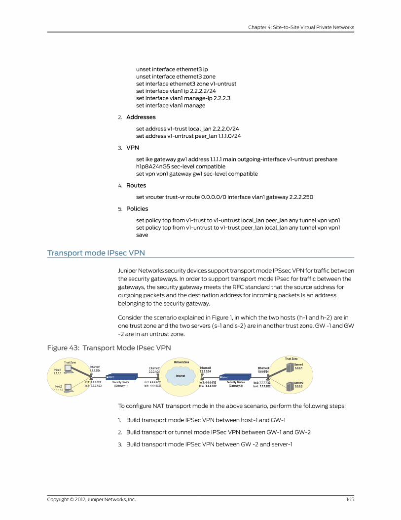
unset interface ethernet3 ipunset interface ethernet3 zoneset interface ethernet3 zone v1-untrustset interface vlan1 ip 2.2.2.2/24set interface vlan1 manage-ip 2.2.2.3set interface vlan1 manage
2. Addresses
set address v1-trust local_lan 2.2.2.0/24set address v1-untrust peer_lan 1.1.1.0/24
3. VPN
set ike gateway gw1 address 1.1.1.1 main outgoing-interface v1-untrust preshareh1p8A24nG5 sec-level compatibleset vpn vpn1 gateway gw1 sec-level compatible
4. Routes
set vrouter trust-vr route 0.0.0.0/0 interface vlan1 gateway 2.2.2.250
5. Policies
set policy top from v1-trust to v1-untrust local_lan peer_lan any tunnel vpn vpn1set policy top from v1-untrust to v1-trust peer_lan local_lan any tunnel vpn vpn1save
Transport mode IPsec VPN
Juniper Networks security devices support transport mode IPSsec VPN for traffic between
the security gateways. In order to support transport mode IPsec for traffic between the
gateways, the security gateway meets the RFC standard that the source address for
outgoing packets and the destination address for incoming packets is an address
belonging to the security gateway.
Consider the scenario explained in Figure 1, in which the two hosts (h-1 and h-2) are in
one trust zone and the two servers (s-1 and s-2) are in another trust zone. GW -1 and GW
-2 are in an untrust zone.
Figure 43: Transport Mode IPsec VPN
To configure NAT transport mode in the above scenario, perform the following steps:
1. Build transport mode IPSec VPN between host-1 and GW-1
2. Build transport or tunnel mode IPSec VPN between GW-1 and GW-2
3. Build transport mode IPSec VPN between GW -2 and server-1
165Copyright © 2012, Juniper Networks, Inc.
Chapter 4: Site-to-Site Virtual Private Networks

4. Do source-NAT and MIP on GW-1
5. Do MIP ( MIP and reversed MIP) on GW-2.
The following section explains the steps involved in configuring a transport mode IPsec
VPN. GW-1 uses src-NAT when h-1 is accessing s-1, and GW-2 uses MIP when h-2 is
accessing s-2.
Gateway - 1 Configuration
1. IKE configuration on host-1 and host-2
set ike gateway gateway1 address 1.1.1.1 aggressive outgoing-interface loopback.1preshare test1 sec-level standardset ike gateway gateway2 address 1.1.1.10 aggressive outgoing-interface loopback.2preshare test1 sec-level standard
2. VPN cnfiguration on host-1 and host-2
set vpn v1 gateway gateway1 transport sec-level standardset vpn v2 gateway gateway2 transport sec-level standard
3. Proxy configuration for v1 and v2
set vpn "v1" proxy-id local-ip 4.4.4.4/32 remote-ip 6.6.6.6/32 "ANY"set vpn "v2" proxy-id local-ip 4.4.4.5/32 remote-ip 4.4.4.7/32 "ANY"
4. MIP configuration
set interface loopback.1 mip 3.3.3.3 host 6.6.6.6set interface loopback.2 mip 3.3.3.4 host 6.6.6.7
5. IKE configuration for GW-2
set ike gateway s1 address 6.6.6.6 aggressive outgoing-interface loopback.3 presharetest1 sec-level standardset ike gateway s2 address 6.6.6.7 aggressive outgoing-interface loopback.4 presharetest1 sec-level standard
6. VPN configuration for s1 and s2
set vpn v3 gateway s1 transport sec-level standardset vpn v4 gateway s2 transport sec-level standard
7. DIP configuration
set interface eth2 ext ip 4.4.4.4 255.255.255.255 dip 10 4.4.4.4 4.4.4.4set interface eth2 ext ip 4.4.4.5 255.255.255.255 dip 11 4.4.4.5 4.4.4.5
8. Policy Setup
Outgoing policy
set policy id 3 from trust to untrust "1.1.1.1" "3.3.3.3" any nat src dip-id 10 tunnel vpnv3set policy id 4 from trust to untrust "1.1.1.10" "3.3.3.4" any nat src dip-id 11 tunnel vpnv4
Incoming policy
set policy id 1 from trust to untrust "1.1.1.1" "(MIP)3.3.3.3" any tunnel vpn v1set policy id 2 from trust to untrust "1.1.1.10" "(MIP)3.3.3.4" any tunnel vpn v2
Copyright © 2012, Juniper Networks, Inc.166
Virtual Private Networks

NOTE: Users need to configure the outgoing policy before configuirng theincoming policy. This is because we do policy search twice, the first oneis to check the incoming packet, and the second one is to find anotherVPN (the outgoing VPN) through which we send the packet.
9. Flow check
set flow ply-chk-self-out-tunnel
GW-2 Configuration
8. IKE and VPN configuration to server-PC
set ike gateway gateway1 address 5.0.0.1 aggressive outgoing-interface lo.3 presharetest sec-level standardset ikegatewaygateway2address 5.0.0.2aggressiveoutgoing-interface lo.4presharetest sec-level standard
9. VPN configuration on server-1 and server-2
set vpn v3 gateway gateway1 transport sec-level standardset vpn v4 gateway gateway2 transport sec-level standard
10. Proxy configuration for v3 and v4
set vpn "v3" proxy-id local-ip 3.3.3.3/32 remote-ip 1.1.1.1/32 "ANY"set vpn "v4" proxy-id local-ip 3.3.3.4/32 remote-ip 1.1.1.10/32 "ANY"
11. ReversedMIP (traffic is from untrust to trust)
set interface lo.3 mip 7.7.7.7 host 4.4.4.4set interface lo.4mip 7.7.7.8 host 4.4.4.5
12. IKE and VPN configuration to GW-1 (Client-PC)
set ike gateway h1 address 4.4.4.4 aggressive outgoing-interface lo.1 preshare testsec-level standardset ike gateway h2 address 4.4.4.5 aggressive outgoing-interface lo.2 preshare testsec-level standard
13. VPN configuration on host-1 and host-2
set vpn v1 gateway h1 transport sec-level standardset vpn v2 gateway h2 transport sec-level standard
14. MIP
set interface lo.1 mip 6.6.6.6 host 5.0.0.1set interface lo.2 mip 6.6.6.7 host 5.0.0.2
15. Policy setup
Outgoing policy
set policy id 7 from untrust to trust "4.4.4.4" "6.6.6.6" any tunnel vpn v3set policy id 8 from untrust to trust "4.4.4.5" "6.6.6.7" any tunnel vpn v4
Incoming policy
167Copyright © 2012, Juniper Networks, Inc.
Chapter 4: Site-to-Site Virtual Private Networks

set policy id 5 from untrust to trust "4.4.4.4" "(MIP)6.6.6.6" any tunnel vpn v1set policy id 6 from untrust to trust "4.4.4.5" "(MIP)6.6.6.7" any tunnel vpn v2
1. When a packet from h-1 arrives at GW-1, the GW-1 decrypts the packet and finds the
destination MIP for the packet.
2. GW-1 matches the packet against the policy (policy 1) that defines the host VPN. It
does a policy search again and finds the policy (policy 3) that defines the server VPN
and src-nat.
3. GW-1 then does a destination MIP, which changes the destination IP address from
3.3.3.3 to 6.6.6.6 and the source NAT, which changes the source IP address from 1.1.1.1
to 4.4.4.4.
4. GW-2 decrypts the packet and finds the destination MIP for the packet.
It matches the decrypted packet with the policy (policy 5) that defines the host VPN.
It does a policy search again and finds the policy (policy 7) that defines the server
VPN.
5. Before sending the packet out, GW-2 finds the reversed-MIP on lo.3 for packet's src-IP
4.4.4.4, so the src-ip is changed from 4.4.4.4 to 7.7.7.7
6. GW-2 forwards the packet to s-1 through interface 7.7.7.7
7. S-1 (5.0.0.1) processes the packet and sends it to GW-2 (6.6.6.6) through interface
7.7.7.7.
8. GW-2 identifies the reversed MIP (7.7.7.7 -> 4.4.4.4) and sends the packet to GW-1
(4.4.4.4). From GW-1, the packet is sent to h-1.
9. Flow check
set flow ply-chk-self-out-tunnel
Copyright © 2012, Juniper Networks, Inc.168
Virtual Private Networks

CHAPTER 5
Dialup Virtual Private Networks
Juniper Networks security devices can support dialup virtual private network (VPN)
connections. You can configure a security device that has a static IP address to secure
an IPsec tunnel with a NetScreen-Remote client or with another security device with a
dynamic IP address.
This chapter contains the following sections:
• Dialup on page 169
• Group IKE ID on page 191
• Shared IKE ID on page 206
Dialup
You can configure tunnels for VPN dialup users individually, or you can form users into a
VPN dialup group for which you need only configure one tunnel. You can also create a
Group IKE ID user that allows you to define one user whose IKE ID is used as part of the
IKE IDs of dialup IKE users. This approach is particularly timesaving when there are large
groups of dialup users because you do not have to configure each IKE user individually.
NOTE: For more information about creating IKE user groups, see IKE Userand User Groups. For more information about the Group IKE ID feature, see“Group IKE ID” on page 191.
If the dialup client can support a virtual internal IP address, which the NetScreen-Remote
does, you can also create a dynamic peer dialup VPN, AutoKey IKE tunnel (with a
preshared key or certificates). You can configure a Juniper Networks security gateway
with a static IP address to secure an IPsec tunnel with a NetScreen-Remote client or
with another security device with a dynamic IP address.
NOTE: For background information about the available VPN options, see“Internet Protocol Security” on page 3. For guidance when choosing amongthe various options, see “Virtual Private Network Guidelines” on page 61.
169Copyright © 2012, Juniper Networks, Inc.

You can configure policy-based VPN tunnels for VPN dialup users. For a dialup dynamic
peer client, you can configure either a policy-based or route-based VPN. Because a dialup
dynamic peer client can support a virtual internal IP address, which the NetScreen-Remote
does, you can configure a routing table entry to that virtual internal address through a
designated tunnel interface. Doing so allows you to configure a route-based VPN tunnel
between the security device and that peer.
NOTE: A dialup dynamic peer client is a dialup client that supports a virtualinternal IP address.
The dialup dynamic peer is nearly identical to the Site-to-Site dynamic peerexcept that the internal IP address for the dialup client is a virtual address.
Policy-Based Dialup VPN, AutoKey IKE
In this example, an AutoKey IKE tunnel using either a preshared key or a pair of certificates
(one at each end of the tunnel) provides the secure communication channel between
the IKE user Wendy and the UNIX server. The tunnel again uses ESP with 3DES encryption
and SHA-1 authentication.
NOTE: Thepresharedkey ish1p8A24nG5. It isassumedthatbothparticipantsalready have certificates. For more information about certificates, see“Certificates and CRLs” on page 39.
Setting up the AutoKey IKE tunnel using AutoKey IKE with either a preshared key or
certificates requires the following configuration at the corporate site:
1. Configure interfaces for the Trust and Untrust zones, both of which are in the trust-vr
routing domain.
2. Enter the address of the UNIX server in the Trust zone address book.
3. Define Wendy as an IKE user.
4. Configure the remote gateway and AutoKey IKE VPN.
5. Set up a default route.
6. Create a policy from the Untrust zone to the Trust zone permitting access to the UNIX
from the dialup user.
Copyright © 2012, Juniper Networks, Inc.170
Virtual Private Networks

Figure 44: Policy-Based Dialup VPN, AutoKey IKE
The preshared key is h1p8A24nG5. This example assumes that both participants already
have RSA certificates issued by Verisign and that the local certificate on the
NetScreen-Remote contains the U-FQDN [email protected]. (For information about
obtaining and loading certificates, see “Certificates and CRLs” on page 39.) For the Phase 1
and 2 security levels, you specify one Phase 1 proposal—either pre-g2-3des-sha for the
preshared key method or rsa-g2-3des-sha for certificates—and select the predefined
“Compatible” set of proposals for Phase 2.
WebUI
1. Interfaces
Network > Interfaces > Edit (for ethernet1): Enter the following, then click Apply:
Zone Name: TrustStatic IP: (select this option when present)IP Address/Netmask: 10.1.1.1/24
Select the following, then clickOK:Interface Mode: NAT
Network > Interfaces > Edit (for ethernet3): Enter the following, then click OK:
Zone Name: UntrustStatic IP: (select this option when present)IP Address/Netmask: 1.1.1.1/24
2. Address
Policy > Policy Elements > Addresses > List > New: Enter the following, then clickOK:
Address Name: UNIXIP Address/Domain Name:IP/Netmask: (select), 10.1.1.5/32
Zone: Trust
3. User
Objects > Users > Local > New: Enter the following, then click OK:
User Name:WendyStatus: Enable (select)IKE User: (select)Simple Identity: (select)IKE Identity: [email protected]
171Copyright © 2012, Juniper Networks, Inc.
Chapter 5: Dialup Virtual Private Networks

4. VPN
VPNs > AutoKey Advanced > Gateway > New: Enter the following, then click OK:
Gateway Name:Wendy_NSRSecurity Level: CustomRemote Gateway Type:Dialup User: (select), User: Wendy
Certificates
Outgoing Interface: ethernet3
> Advanced: Enter the following advanced settings, then click Return to return to the
basic Gateway configuration page:
Security Level: CustomPhase 1 Proposal (For Custom Security Level): rsa-g2-3des-shaMode (Initiator): AggressivePreferred Certificate (optional):Peer CA: VerisignPeer Type: X509-SIG
VPNs > AutoKey IKE > New: Enter the following, then click OK:
VPNName:Wendy_UNIXSecurity Level: CompatibleRemote Gateway:Predefined: (select), Wendy_NSR
(or)
Preshared Key
CAUTION: Aggressivemode is insecure. Because of protocol limitations,mainmode IKE in combination with preshared key (PSK) is not possiblefor dialup VPN users. In addition, it is never advisable to use aggressivemode because this mode has inherent security problems. Consequently,it is strongly advisable to configure dialup VPN users with PKI certificatesandmainmode.
Preshared Key: h1p8A24nG5Outgoing Interface: ethernet3
> Advanced: Enter the following advanced settings, then click Return to return to the
basic Gateway configuration page:
Security Level: CustomPhase 1 Proposal (For Custom Security Level): pre-g2-3des-shaMode (Initiator): Aggressive
5. Route
Network > Routing > Routing Entries > trust-vr New: Enter the following, then click
OK:
Network Address/Netmask: 0.0.0.0/0Gateway: (select)
Copyright © 2012, Juniper Networks, Inc.172
Virtual Private Networks
Interface: ethernet3Gateway IP Address: 1.1.1.250
6. Policy
Policies > (From: Untrust, To: Trust) New: Enter the following, then click OK:
Source Address:Address Book Entry: (select), Dial-Up VPN
Destination Address:Address Book Entry: (select), UNIX
Service: ANYAction: TunnelTunnel VPN:Wendy_UNIXModify matching bidirectional VPN policy: (clear)Position at Top: (select)
CLI
1. Interfaces
set interface ethernet1 zone trustset interface ethernet1 ip 10.1.1.1/24set interface ethernet1 natset interface ethernet3 zone untrustset interface ethernet3 ip 1.1.1.1/24
2. Address
set address trust unix 10.1.1.5/32
3. User
set user wendy ike-id u-fqdn [email protected]
4. VPN
Certificates
set ike gateway wendy_nsr dialup wendy aggressive outgoing-interface ethernet3proposal rsa-g2-3des-shaset ike gateway wendy_nsr cert peer-ca 1set ike gateway wendy_nsr cert peer-cert-type x509-sigset vpn wendy_unix gateway wendy_nsr sec-level compatible
NOTE: The number 1 is the CA ID number. To discover the CA’s ID number,use the following command: get pki x509 list ca-cert.
(or)
Preshared Key
CAUTION: Aggressivemode is insecure. Due to protocol limitations,mainmode IKE in combination with preshared key (PSK) is not possible fordialupVPNusers. In addition, it is never advisable to use aggressivemodebecause this mode has inherent insecurity problems. Consequently, it is
173Copyright © 2012, Juniper Networks, Inc.
Chapter 5: Dialup Virtual Private Networks

strongly advisable to configure dialupVPNuserswith PKI certificates andmainmode.
set ike gateway wendy_nsr dialup wendy aggressive outgoing-interface ethernet3preshare h1p8A24nG5 proposal pre-g2-3des-shaset vpn wendy_unix gateway wendy_nsr sec-level compatible
5. Route
set vrouter trust-vr route 0.0.0.0/0 interface ethernet3 gateway 1.1.1.250
6. Policy
set policy top from untrust to trust “Dial-Up VPN” unix any tunnel vpn wendy_unixsave
NetScreen-Remote Security Policy Editor
1. Click Options > Secure > Specified Connections.
2. Click Add a new connection, and type UNIX next to the new connection icon that
appears.
3. Configure the connection options:
Connection Security: SecureRemote Party Identity and Addressing:ID Type: IP Address, 10.1.1.5Protocol: AllConnect using Secure Gateway Tunnel: (select)ID Type: IP Address, 1.1.1.1
4. Click thePLUS symbol, located to the left of the UNIX icon, to expand the connection
policy.
5. Click My Identity: Do either of the following:
Click Pre-shared Key > Enter Key: Type h1p8A24nG5, then click OK.
ID Type: (select E-mail Address), and type [email protected].
(or)
Select a certificate from the Select Certificate drop-down list.
ID Type: (select E-mail Address)
NOTE: The email address from the certificate automatically appears inthe identifier field.
6. Click theSecurityPolicy icon, then selectAggressiveMode and clearEnable PerfectForward Secrecy (PFS).
7. Click the PLUS symbol, located to the left of the Security Policy icon, and then the
PLUS symbol to the left of Authentication (Phase 1) and Key Exchange (Phase 2) to
expand the policy further.
Copyright © 2012, Juniper Networks, Inc.174
Virtual Private Networks
8. Click Authentication (Phase 1) > Proposal 1: Select the following authentication
method and algorithms:
Authentication Method: Pre-Shared Key
(or)
Authentication Method: RSA SignaturesEncrypt Alg: Triple DESHash Alg: SHA-1Key Group: Diffie-Hellman Group 2
9. Click Key Exchange (Phase 2) > Proposal 1: Select the following IPsec protocols:
Encapsulation Protocol (ESP): (select)Encrypt Alg: Triple DESHash Alg: SHA-1Encapsulation: Tunnel
10. Click Key Exchange (Phase 2) > Create NewProposal: Select the following IPsec
protocols:
Encapsulation Protocol (ESP): (select)Encrypt Alg: Triple DESHash Alg: MD5Encapsulation: Tunnel
11. Click Key Exchange (Phase 2) > Create NewProposal: Select the following IPsec
protocols:
Encapsulation Protocol (ESP): (select)Encrypt Alg: DESHash Alg: SHA-1Encapsulation: Tunnel
12. Click Key Exchange (Phase 2) > Create NewProposal: Select the following IPsec
protocols:
Encapsulation Protocol (ESP): (select)Encrypt Alg: DESHash Alg: MD5Encapsulation: Tunnel
13. Click File > Save Changes.
Route-Based Dialup VPN, Dynamic Peer
In this example, a VPN tunnel securely connects the user behind NetScreen-Remote to
the Untrust zone interface of the security device protecting the mail server in the DMZ
zone. The Untrust zone interface has a static IP address. The NetScreen-Remote client
has a dynamically assigned external IP address and a static (virtual) internal IP address.
The administrator of the security device must know the peer’s internal IP address for the
following two purposes:
• The admin can use it in policies.
• The admin can create a route linking the address with a tunnel interface bound to an
appropriate tunnel.
175Copyright © 2012, Juniper Networks, Inc.
Chapter 5: Dialup Virtual Private Networks

After the NetScreen-Remote client establishes the tunnel, traffic through the tunnel can
then originate from either end. All zones on the security device are in the trust-vr routing
domain.
Figure 45: Route-Based Dialup VPN, Dynamic Peer
In this example, Phil wants to get his email from the mail server at the company site.
When he attempts to do so, he is authenticated by the mail server program, which sends
him an IDENT request through the tunnel.
NOTE: Themail server can send the IDENT request through the tunnel onlyif the security administrator adds a custom service for it (TCP, port 113) andsetsupanoutgoingpolicyallowing that traffic through the tunnel to 10.10.10.1.
The preshared key is h1p8A24nG5. It is assumed that both participants already have RSA
certificates issued by Verisign and that the local certificate on the NetScreen-Remote
contains the U-FQDN [email protected]. (For information about obtaining and loading
certificates, see “Certificates and CRLs” on page 39.) For the Phase 1 and Phase 2 security
levels, you specify one Phase 1 proposal—either pre-g2-3des-sha for the preshared key
method or rsa-g2-3des-sha for certificates—and select the predefined “Compatible” set
of proposals for Phase 2.
You enter the following three routes on the security device:
• A default route to the external router in the trust-vr
• A route to the destination through the tunnel interface
• A null route to the destination. You assign a higher metric (farther from zero) to the
null route so that it becomes the next-choice route to the destination. Then, if the state
of the tunnel interface changes to “down” and the route referencing that interface
becomes inactive, the security device uses the null route, which essentially drops any
traffic sent to it, rather than the default route, which forwards unencrypted traffic.
Finally, you create policies allowing traffic to flow in both directions between Phil and
the mail server.
WebUI
1. Interfaces
Network > Interfaces > Edit (for ethernet2): Enter the following, then click OK:
Copyright © 2012, Juniper Networks, Inc.176
Virtual Private Networks

Zone Name: DMZStatic IP: (select this option when present)IP Address/Netmask: 1.2.2.1/24
Network > Interfaces > Edit (for ethernet3): Enter the following, then click OK:
Zone Name: UntrustStatic IP: (select this option when present)IP Address/Netmask: 1.1.1.1/24
Network > Interfaces > New Tunnel IF: Enter the following, then click OK:
Tunnel Interface Name: tunnel.1Zone (VR): Untrust (trust-vr)Unnumbered: (select)Interface: ethernet3 (trust-vr)
2. Addresses
Policy > Policy Elements > Addresses > List > New: Enter the following, then clickOK:
Address Name: Mail ServerIP Address/Domain Name:IP/Netmask: (select), 1.2.2.5/32
Zone: DMZ
Policy > Policy Elements > Addresses > List > New: Enter the following, then clickOK:
Address Name: PhilIP Address/Domain Name:IP/Netmask: (select), 10.10.10.1/32
Zone: Untrust
3. Services
Policy > Policy Elements > Services > Custom > New: Enter the following, then click
OK:
Service Name: IdentService Timeout:Use protocol default: (select)
Transport Protocol: TCP (select)Source Port: Low 1, High 65535Destination Port: Low 113, High 113
Policy > Policy Elements > Services > Group > New: Enter the following, move the
following services, then click OK:
Group Name: Remote_MailGroupMembers << Available Members:IdentMAILPOP3
4. VPN
VPNs > AutoKey Advanced > Gateway > New: Enter the following, then click OK:
Gateway Name: To_PhilSecurity Level: Custom
177Copyright © 2012, Juniper Networks, Inc.
Chapter 5: Dialup Virtual Private Networks

Remote Gateway Type:Dynamic IP Address: (select), Peer ID: [email protected]
Preshared Key
Preshared Key: h1p8A24nG5Outgoing Interface: ethernet3
> Advanced: Enter the following advanced settings, then click Return to return to the
basic Gateway configuration page:
Security Level: CustomPhase 1 Proposal (For Custom Security Level): pre-g2-3des-shaMode (Initiator): Aggressive
(or)
Certificates
Outgoing Interface: ethernet3
> Advanced: Enter the following advanced settings, then click Return to return to the
basic Gateway configuration page:
Security Level: CustomPhase 1 Proposal (For Custom Security Level): rsa-g2-3des-shaMode (Initiator): AggressivePreferred Certificate (optional):Peer CA: VerisignPeer Type: X509-SIG
VPNs > AutoKey IKE > New: Enter the following, then click OK:
VPNName: corp_PhilSecurity Level: CompatibleRemote Gateway:Predefined: (select), To_Phil
> Advanced: Enter the following advanced settings, then click Return to return to the
basic AutoKey IKE configuration page:
Bind to: Tunnel Interface: (select), tunnel.1Proxy-ID: (select)Local IP / Netmask: 1.2.2.5/32Remote IP / Netmask: 10.10.10.1/32Service: Any
5. Routes
Network > Routing > Routing Entries > trust-vr New: Enter the following, then click
OK:
Network Address/Netmask: 0.0.0.0/0Gateway: (select)Interface: ethernet3Gateway IP Address: 1.1.1.250
Network > Routing > Routing Entries > trust-vr New: Enter the following, then click
OK:
Network Address/Netmask: 10.10.10.1/32Gateway: (select)
Copyright © 2012, Juniper Networks, Inc.178
Virtual Private Networks

Interface: tunnel.1Gateway IP Address: 0.0.0.0
Network > Routing > Routing Entries > trust-vr New: Enter the following, then click
OK:
Network Address/Netmask: 10.10.10.1/32Gateway: (select)Interface: NullGateway IP Address: 0.0.0.0Metric: 10
6. Policies
Policies > (From: Untrust, To: DMZ) New: Enter the following, then click OK:
Source Address:Address Book Entry: (select), Phil
Destination Address:Address Book Entry: (select), Mail Server
Service: Remote_MailAction: PermitPosition at Top: (select)
Policies > (From: DMZ, To: Untrust) New: Enter the following, then click OK:
Source Address:Address Book Entry: (select), Mail Server
Destination Address:Address Book Entry: (select), Phil
Service: Remote_MailAction: PermitPosition at Top: (select)
CLI
1. Interfaces
set interface ethernet2 zone dmzset interface ethernet2 ip 1.2.2.1/24set interface ethernet3 zone untrustset interface ethernet3 ip 1.1.1.1/24set interface tunnel.1 zone untrustset interface tunnel.1 ip unnumbered interface ethernet3
2. Addresses
set address dmz “Mail Server” 1.2.2.5/32set address untrust phil 10.10.10.1/32
3. Services
set service ident protocol tcp src-port 1-65535 dst-port 113-113set group service remote_mailset group service remote_mail add identset group service remote_mail addmailset group service remote_mail add pop3
4. VPN
179Copyright © 2012, Juniper Networks, Inc.
Chapter 5: Dialup Virtual Private Networks

Preshared Key
set ike gateway to_phil dynamic [email protected] aggressive outgoing-interfaceethernet3 preshare h1p8A24nG5 proposal pre-g2-3des-shaset vpn corp_phil gateway to_phil sec-level compatibleset vpn corp_phil bind interface tunnel.1set vpn corp_phil proxy-id local-ip 1.2.2.5/32 remote-ip 10.10.10.1/32 any
(or)
Certificates
set ike gateway to_phil dynamic [email protected] aggressive outgoing-interfaceethernet3 proposal rsa-g2-3des-shaset ike gateway to_phil cert peer-ca 1set ike gateway to_phil cert peer-cert-type x509-sigset vpn corp_phil gateway to_phil sec-level compatibleset vpn corp_phil bind interface tunnel.1set vpn corp_phil proxy-id local-ip 1.2.2.5/32 remote-ip 10.10.10.1/32 any
NOTE: The number 1 is the CA ID number. To discover the CA’s ID number,use the following command: get pki x509 list ca-cert.
5. Routes
set vrouter trust-vr route 0.0.0.0/0 interface ethernet3 gateway 1.1.1.250set vrouter trust-vr route 10.10.10.1/32 interface tunnel.1set vrouter trust-vr route 10.10.10.1/32 interface null metric 10
6. Policies
set policy top from dmz to untrust “Mail Server” phil remote_mail permitset policy top from untrust to dmz phil “Mail Server” remote_mail permitsave
NetScreen-Remote
1. Click Options > Global Policy Settings, and select the Allow to Specify Internal
Network Address check box.
2. Options > Secure > Specified Connections.
3. Click the Add a new connection button, and type Mail next to the new connection
icon that appears.
4. Configure the connection options:
Connection Security: SecureRemote Party Identity and Addressing:ID Type: IP Address, 1.2.2.5Protocol: AllConnect using Secure Gateway Tunnel: (select)ID Type: IP Address, 1.1.1.1
5. Click thePLUS symbol, located to the left of the UNIX icon, to expand the connection
policy.
Copyright © 2012, Juniper Networks, Inc.180
Virtual Private Networks
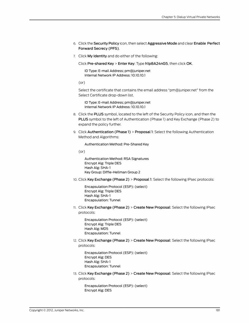
6. Click theSecurityPolicy icon, then selectAggressiveMode and clearEnable PerfectForward Secrecy (PFS).
7. Click My Identity and do either of the following:
Click Pre-shared Key > Enter Key: Type h1p8A24nG5, then click OK.
ID Type: E-mail Address; [email protected] Network IP Address: 10.10.10.1
(or)
Select the certificate that contains the email address “[email protected]” from the
Select Certificate drop-down list.
ID Type: E-mail Address; [email protected] Network IP Address: 10.10.10.1
8. Click the PLUS symbol, located to the left of the Security Policy icon, and then the
PLUS symbol to the left of Authentication (Phase 1) and Key Exchange (Phase 2) to
expand the policy further.
9. Click Authentication (Phase 1) > Proposal 1: Select the following Authentication
Method and Algorithms:
Authentication Method: Pre-Shared Key
(or)
Authentication Method: RSA SignaturesEncrypt Alg: Triple DESHash Alg: SHA-1Key Group: Diffie-Hellman Group 2
10. Click Key Exchange (Phase 2) > Proposal 1: Select the following IPsec protocols:
Encapsulation Protocol (ESP): (select)Encrypt Alg: Triple DESHash Alg: SHA-1Encapsulation: Tunnel
11. Click Key Exchange (Phase 2) > Create NewProposal: Select the following IPsec
protocols:
Encapsulation Protocol (ESP): (select)Encrypt Alg: Triple DESHash Alg: MD5Encapsulation: Tunnel
12. Click Key Exchange (Phase 2) > Create NewProposal: Select the following IPsec
protocols:
Encapsulation Protocol (ESP): (select)Encrypt Alg: DESHash Alg: SHA-1Encapsulation: Tunnel
13. Click Key Exchange (Phase 2) > Create NewProposal: Select the following IPsec
protocols:
Encapsulation Protocol (ESP): (select)Encrypt Alg: DES
181Copyright © 2012, Juniper Networks, Inc.
Chapter 5: Dialup Virtual Private Networks

Hash Alg: MD5Encapsulation: Tunnel
14. Click File > Save Changes.
Policy-Based Dialup VPN, Dynamic Peer
In this example, a VPN tunnel securely connects the user behind the NetScreen-Remote
to the Untrust zone interface of the security device protecting the mail server in the DMZ
zone. The Untrust zone interface has a static IP address. The NetScreen-Remote client
has a dynamically assigned external IP address and a static (virtual) internal IP address.
The administrator of the security device must know the client’s internal IP address so
that he can add it to the Untrust address book for use in policies to tunnel traffic from
that source. After the NetScreen-Remote client establishes the tunnel, traffic through
the tunnel can originate from either end.
Figure 46: Policy-Based Dialup VPN, Dynamic Peer
SMTPRequest
IDENTRequest
Remote User: PhilNetScreen-Remote
Outgoing InterfaceUntrust Zone
ethernet3, 1.1.1.1/24Gateway 1.1.1.250
Corporate OfficeDMZ Zone
ethernet2, 1.2.2.1/24
Internal IP Address10.10.10.1
External IP AddressDynamic
Untrust Zone DMZ Zone
Mail Server1.2.2.5
Internet
VPN Tunnel
In this example, Phil wants to get his email from the mail server at the company site.
When he attempts to do so, he is authenticated by the mail server program, which sends
him an IDENT request through the tunnel.
NOTE: Themail server can send the IDENT request through the tunnel onlyif the security administrator adds a custom service for it (TCP, port 113) andsetsupanoutgoingpolicyallowing that traffic through the tunnel to 10.10.10.1.
The preshared key is h1p8A24nG5. This example assumes that both participants have
RSA certificates issued by Verisign and that the local certificate on the NetScreen-Remote
contains the [email protected]. (For more information about obtaining and loading
certificates, see “Certificates and CRLs” on page 39.) For the Phase 1 and Phase 2 security
levels, you specify one Phase 1 proposal—either pre-g2-3des-sha for the preshared key
method or rsa-g2-3des-sha for certificates—and select the predefined “Compatible” set
of proposals for Phase 2.
WebUI
1. Interfaces
Network > Interfaces > Edit (for ethernet2): Enter the following, then click OK:
Copyright © 2012, Juniper Networks, Inc.182
Virtual Private Networks

Zone Name: DMZStatic IP: (select this option when present)IP Address/Netmask: 1.2.2.1/24
Network > Interfaces > Edit (for ethernet3): Enter the following, then click OK:
Zone Name: UntrustStatic IP: (select this option when present)IP Address/Netmask: 1.1.1.1/24
2. Addresses
Policy > Policy Elements > Addresses > List > New: Enter the following, then clickOK:
Address Name: Mail ServerIP Address/Domain Name:IP/Netmask: (select), 1.2.2.5/32
Zone: DMZ
Policy > Policy Elements > Addresses > List > New: Enter the following, then clickOK:
Address Name: PhilIP Address/Domain Name:IP/Netmask: (select), 10.10.10.1/32
Zone: Untrust
3. Services
Policy > Policy Elements > Services > Custom > New: Enter the following, then click
OK:
Service Name: IdentService Timeout:Use protocol default: (select)
Transport Protocol: TCP (select)Source Port: Low 1, High 65535Destination Port: Low 113, High 113
Policy > Policy Elements > Services > Group > New: Enter the following, move the
following services, then click OK:
Group Name: Remote_MailGroupMembers << Available Members:IdentMAILPOP3
4. VPN
VPNs > AutoKey Advanced > Gateway > New: Enter the following, then click OK:
Gateway Name: To_PhilSecurity Level: CustomRemote Gateway Type:Dynamic IP Address: (select), Peer ID: [email protected]
Preshared Key
Preshared Key: h1p8A24nG5Outgoing Interface: ethernet3
183Copyright © 2012, Juniper Networks, Inc.
Chapter 5: Dialup Virtual Private Networks

> Advanced: Enter the following advanced settings, then click Return to return to the
basic Gateway configuration page:
Security Level: CustomPhase 1 Proposal (For Custom Security Level): pre-g2-3des-shaMode (Initiator): Aggressive
(or)
Certificates
Outgoing Interface: ethernet3
> Advanced: Enter the following advanced settings, then click Return to return to the
basic Gateway configuration page:
Security Level: CustomPhase 1 Proposal (For Custom Security Level): rsa-g2-3des-shaMode (Initiator): AggressivePreferred Certificate (optional):Peer CA: VerisignPeer Type: X509-SIG
VPNs > AutoKey IKE > New: Enter the following, then click OK:
VPNName: corp_PhilSecurity Level: CompatibleRemote Gateway:Predefined: (select), To_Phil
5. Route
Network > Routing > Routing Entries > trust-vr New: Enter the following, then click
OK:
Network Address/Netmask: 0.0.0.0/0Gateway: (select)Interface: ethernet3Gateway IP Address: 1.1.1.250
6. Policies
Policies > (From: Untrust, To: DMZ) New: Enter the following, then click OK:
Source Address:Address Book Entry: (select), Phil
Destination Address:Address Book Entry: (select), Mail Server
Service: Remote_MailAction: TunnelVPN Tunnel: corp_PhilModify matching bidirectional VPN policy: (select)Position at Top: (select)
CLI
1. Interfaces
set interface ethernet2 zone dmzset interface ethernet2 ip 1.2.2.1/24
Copyright © 2012, Juniper Networks, Inc.184
Virtual Private Networks
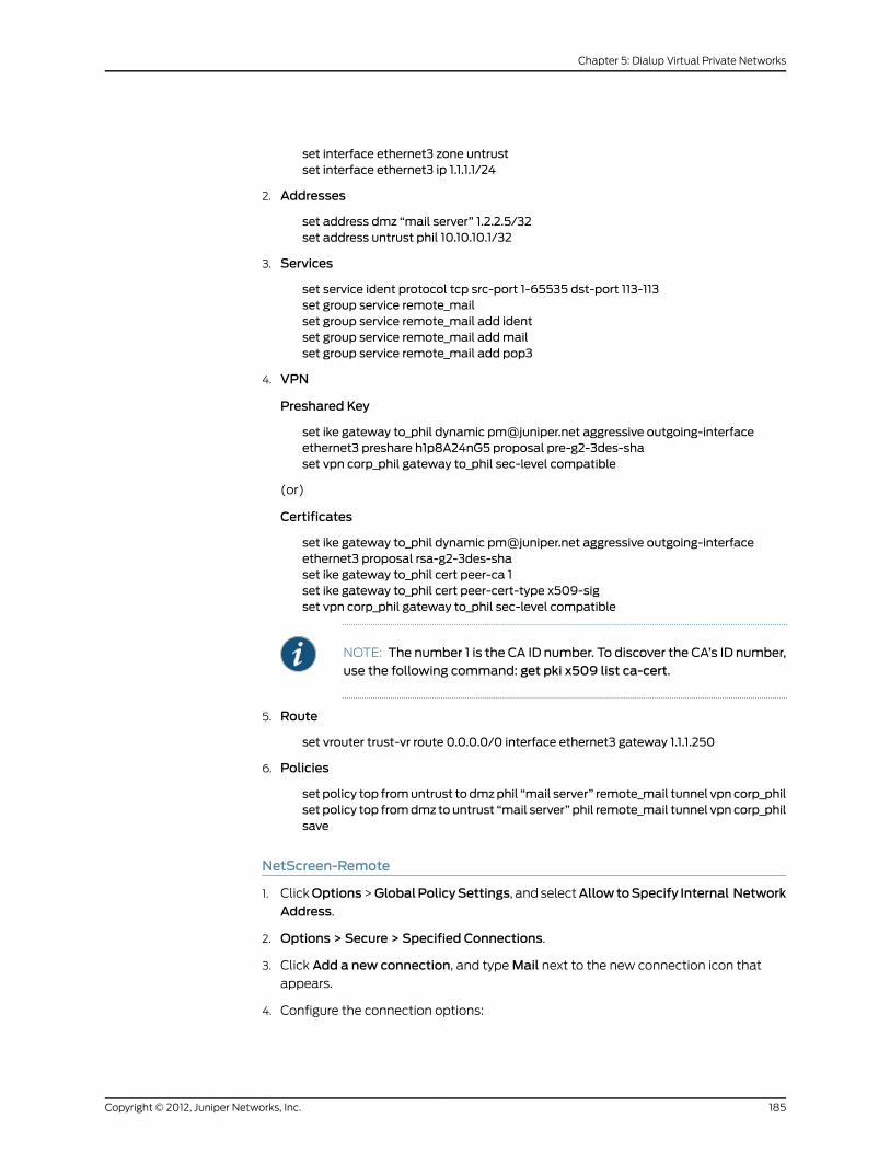
set interface ethernet3 zone untrustset interface ethernet3 ip 1.1.1.1/24
2. Addresses
set address dmz “mail server” 1.2.2.5/32set address untrust phil 10.10.10.1/32
3. Services
set service ident protocol tcp src-port 1-65535 dst-port 113-113set group service remote_mailset group service remote_mail add identset group service remote_mail addmailset group service remote_mail add pop3
4. VPN
Preshared Key
set ike gateway to_phil dynamic [email protected] aggressive outgoing-interfaceethernet3 preshare h1p8A24nG5 proposal pre-g2-3des-shaset vpn corp_phil gateway to_phil sec-level compatible
(or)
Certificates
set ike gateway to_phil dynamic [email protected] aggressive outgoing-interfaceethernet3 proposal rsa-g2-3des-shaset ike gateway to_phil cert peer-ca 1set ike gateway to_phil cert peer-cert-type x509-sigset vpn corp_phil gateway to_phil sec-level compatible
NOTE: The number 1 is the CA ID number. To discover the CA’s ID number,use the following command: get pki x509 list ca-cert.
5. Route
set vrouter trust-vr route 0.0.0.0/0 interface ethernet3 gateway 1.1.1.250
6. Policies
set policy top fromuntrust to dmzphil “mail server” remote_mail tunnel vpn corp_philset policy top fromdmz tountrust “mail server” phil remote_mail tunnel vpn corp_philsave
NetScreen-Remote
1. ClickOptions>GlobalPolicySettings, and selectAllowtoSpecify Internal NetworkAddress.
2. Options > Secure > Specified Connections.
3. Click Add a new connection, and type Mail next to the new connection icon that
appears.
4. Configure the connection options:
185Copyright © 2012, Juniper Networks, Inc.
Chapter 5: Dialup Virtual Private Networks

Connection Security: SecureRemote Party Identity and Addressing:ID Type: IP Address, 1.2.2.5Protocol: AllConnect using Secure Gateway Tunnel: (select)ID Type: IP Address, 1.1.1.1
5. Click thePLUS symbol, located to the left of the UNIX icon, to expand the connection
policy.
6. Click theSecurityPolicy icon, then selectAggressiveMode and clearEnable PerfectForward Secrecy (PFS).
7. Click My Identity and do either of the following:
Click Pre-shared Key > Enter Key: Type h1p8A24nG5, then click OK.
Internal Network IP Address: 10.10.10.1ID Type: E-mail Address; [email protected]
(or)
Select the certificate that contains the email address “[email protected]” from
the Select Certificate drop-down list.
Internal Network IP Address: 10.10.10.1ID Type: E-mail Address; [email protected]
8. Click the PLUS symbol, located to the left of the Security Policy icon, and then the
PLUS symbol to the left of Authentication (Phase 1) and Key Exchange (Phase 2) to
expand the policy further.
9. Click Authentication (Phase 1) > Proposal 1: Select the following Authentication
Method and Algorithms:
Authentication Method: Pre-Shared Key
(or)
Authentication Method: RSA SignaturesEncrypt Alg: Triple DESHash Alg: SHA-1Key Group: Diffie-Hellman Group 2
10. Click Key Exchange (Phase 2) > Proposal 1: Select the following IPsec protocols:
Encapsulation Protocol (ESP): (select)Encrypt Alg: Triple DESHash Alg: SHA-1Encapsulation: Tunnel
11. Click Key Exchange (Phase 2) > Create NewProposal: Select the following IPsec
protocols:
Encapsulation Protocol (ESP): (select)Encrypt Alg: Triple DESHash Alg: MD5Encapsulation: Tunnel
12. Click Key Exchange (Phase 2) > Create NewProposal: Select the following IPsec
protocols:
Copyright © 2012, Juniper Networks, Inc.186
Virtual Private Networks

Encapsulation Protocol (ESP): (select)Encrypt Alg: DESHash Alg: SHA-1Encapsulation: Tunnel
13. Click Key Exchange (Phase 2) > Create NewProposal: Select the following IPsec
protocols:
Encapsulation Protocol (ESP): (select)Encrypt Alg: DESHash Alg: MD5Encapsulation: Tunnel
14. Click File > Save Changes.
Bidirectional Policies for Dialup VPNUsers
You can create bidirectional policies for dialup VPNs. This configuration provides similar
functionality as a dynamic peer VPN configuration. However, with a dynamic peer VPN
configuration, the security device admin must know the internal IP address space of the
dialup user, so that the admin can use it as the destination address when configuring an
outgoing policy (see “Policy-Based Dialup VPN, Dynamic Peer” on page 182). With a dialup
VPN user configuration, the admin at the LAN site does not need to know the internal
address space of the dialup user. The security device protecting the LAN uses the
predefined address “Dial-Up VPN” as the source address in the incoming policy and the
destination in the outgoing policy.
The ability to create bidirectional policies for a dialup VPN tunnel allows traffic to originate
from the LAN end of the VPN connection after the connection has been established.
(The remote end must first initiate the tunnel creation.) Note that unlike a dialup dynamic
peer VPN tunnel, this feature requires that the services on the incoming and outgoing
policies be identical.
NOTE: ScreenOS does not support service groups and address groups inbidirectional policies that reference a dialup VPN configuration.
When creating a VPN policy with an address group and a service group, the proxy ID is
0.0.0.0/0.0.0.0/0/0. When creating a second VPN policy with a different address group
and service group using the same VPN tunnel, the following error message appears:
The new policy id <#> has identical IKE id as that of policy id <#>.. vpn invalid or notexist.
To resolve this error, create a new VPN tunnel using a different IKE gateway with a different
dialup user and IKE ID. The new VPN tunnel creates a new VPN ID. Create the second
policy with a different address group and a service group using the new VPN tunnel. Then,
the proxy ID check refers to the new tunnel.
The internal address space of two or more concurrently connected dialup VPN users
might overlap. For example, dialup users A and B might both have an internal IP address
space of 10.2.2.0/24. If that happens, the security device sends all outbound VPN traffic
187Copyright © 2012, Juniper Networks, Inc.
Chapter 5: Dialup Virtual Private Networks

to both user A and user B through the VPN referenced in the first policy it finds in the
policy list. For example, if the outbound policy referencing the VPN to user A appears first
in the policy list, then the security device sends all outbound VPN traffic intended for
users A and B to user A.
Similarly, the internal address of a dialup user might happen to overlap an address in any
other policy—whether or not that other policy references a VPN tunnel. If that occurs,
the security device applies the first policy that matches the basic traffic attributes of
source address, destination address, source port number, destination port number, service.
To avoid a bidirectional dialup VPN policy with a dynamically derived address superseding
another policy with a static address, Juniper Networks recommends positioning the
bidirectional dialup VPN policy lower in the policy list.
In this example, you configure bidirectional policies for a dialup AutoKey IKE VPN tunnel
named VPN_dial for IKE user dialup-j with IKE ID [email protected]. For Phase 1 negotiations,
you use the proposal pre-g2-3des-sha, with the preshared key Jf11d7uU. You select the
predefined “Compatible” set of proposals for Phase 2 negotiations.
The IKE user initiates a VPN connection to the security device from the Untrust zone to
reach corporate servers in the Trust zone. After the IKE user establishes the VPN
connection, traffic can initiate from either end of the tunnel.
The Trust zone interface is ethernet1, has IP address 10.1.1.1/24, and is in NAT mode. The
Untrust zone interface is ethernet3 and has IP address 1.1.1.1/24. The default route points
to the external router at 1.1.1.250.
WebUI
1. Interfaces
Network > Interfaces > Edit (for ethernet1): Enter the following, then click Apply:
Zone Name: TrustStatic IP: (select this option when present)IP Address/Netmask: 10.1.1.1/24
Select the following, then click OK:
Interface Mode: NAT
Network > Interfaces > Edit (for ethernet3): Enter the following, then click OK:
Zone Name: UntrustStatic IP: (select this option when present)IP Address/Netmask: 1.1.1.1/24
2. Objects
Policy > Policy Elements > Addresses > List > New: Enter the following, then clickOK:
Address Name: trust_netIP Address/Domain Name:IP/Netmask: (select), 10.1.1.0/24
Zone: Trust
Policy > Policy Elements > Users > Local > New: Enter the following, then click OK:
Copyright © 2012, Juniper Networks, Inc.188
Virtual Private Networks

User Name: dialup-jStatus: EnableIKE User: (select)Simple Identity: (select); [email protected]
3. VPN
VPNs > AutoKey Advanced > Gateway > New: Enter the following, then click OK:
Gateway Name: dialup1Security Level: CustomRemote Gateway Type:Dialup User: (select); dialup-j
Preshared Key: Jf11d7uU
> Advanced: Enter the following advanced settings, then click Return to return to the
basic Gateway configuration page:
Security Level: CustomPhase 1 Proposal (For Custom Security Level): pre-g2-3des-shaMode (Initiator): Aggressive
VPNs > AutoKey IKE > New: Enter the following, then click OK:
VPNName: VPN_dialSecurity Level: CompatibleRemote Gateway:Create a Simple Gateway: (select)Gateway Name: dialup1Type:Dialup User: (select); dialup-jPreshared Key: Jf11d7uUSecurity Level: CompatibleOutgoing Interface: ethernet3
4. Route
Network > Routing > Routing Entries > trust-vr New: Enter the following, then click
OK:
Network Address/Netmask: 0.0.0.0/0Gateway: (select)Interface: ethernet1Gateway IP Address: 1.1.1.250
5. Policies
Policies > (From: Untrust, To: Trust) New: Enter the following, then click OK:
Source Address:Address Book Entry: (select), Dial-Up VPN
Destination Address:Address Book Entry: (select), trust_net
Service: ANYAction: TunnelVPN Tunnel: VPN_dialModify matching bidirectional VPN policy: (select)
189Copyright © 2012, Juniper Networks, Inc.
Chapter 5: Dialup Virtual Private Networks

CLI
1. Interfaces
set interface ethernet1 zone trustset interface ethernet1 ip 10.1.1.1/24set interface ethernet1 natset interface ethernet3 zone untrustset interface ethernet3 ip 1.1.1.1/24
2. Objects
set address trust trust_net 10.1.1.0/24set user dialup-j ike-id u-fqdn [email protected]
3. VPN
set ike gateway dialup1 dialup dialup-j aggressive outgoing-interface ethernet3preshare Jf11d7uU proposal pre-g2-3des-shaset vpn VPN_dial gateway dialup1 sec-level compatible
4. Route
set vrouter trust-vr route 0.0.0.0/0 interface ethernet3 gateway 1.1.1.250
5. Policies
set policy from untrust to trust “Dial-Up VPN” trust_net any tunnel vpn VPN_dialset policy from trust to untrust trust_net “Dial-Up VPN” any tunnel vpn VPN_dialsave
NetScreen-Remote Security Policy Editor
1. Click Options > Secure > Specified Connections.
2. Click Add a new connection, and type Corp next to the new connection icon that
appears.
3. Configure the connection options:
Connection Security: SecureRemote Party Identity and AddressingID Type: IP SubnetSubnet: 10.1.1.0Mask: 255.255.255.0Protocol: AllConnect using Secure Gateway Tunnel: (select)ID Type: IP Address, 1.1.1.1
4. Click thePLUS symbol, located to the left of the UNIX icon, to expand the connection
policy.
5. Click My Identity: Do either of the following:
Click Pre-shared Key > Enter Key: Type Jf11d7uU, then click OK.
ID Type: (select E-mail Address), and type [email protected].
6. Click theSecurityPolicy icon, then selectAggressiveMode and clearEnable PerfectForward Secrecy (PFS).
Copyright © 2012, Juniper Networks, Inc.190
Virtual Private Networks

7. Click the PLUS symbol, located to the left of the Security Policy icon, and then the
PLUS symbol to the left of Authentication (Phase 1) and Key Exchange (Phase 2) to
expand the policy further.
8. Click Authentication (Phase 1) > Proposal 1: Select the following Authentication
Method and Algorithms:
Authentication Method: Pre-Shared Key
(or)
Authentication Method: RSA SignaturesEncrypt Alg: Triple DESHash Alg: SHA-1Key Group: Diffie-Hellman Group 2
9. Click Key Exchange (Phase 2) > Proposal 1: Select the following IPsec protocols:
Encapsulation Protocol (ESP): (select)Encrypt Alg: Triple DESHash Alg: SHA-1Encapsulation: Tunnel
10. Click Key Exchange (Phase 2) > Create NewProposal: Select the following IPsec
protocols:
Encapsulation Protocol (ESP): (select)Encrypt Alg: Triple DESHash Alg: MD5Encapsulation: Tunnel
11. Click Key Exchange (Phase 2) > Create NewProposal: Select the following IPsec
protocols:
Encapsulation Protocol (ESP): (select)Encrypt Alg: DESHash Alg: SHA-1Encapsulation: Tunnel
12. Click Key Exchange (Phase 2) > Create NewProposal: Select the following IPsec
protocols:
Encapsulation Protocol (ESP): (select)Encrypt Alg: DESHash Alg: MD5Encapsulation: Tunnel
13. Click File > Save Changes.
Group IKE ID
Some organizations have many dialup VPN users. For example, a sales department might
have hundreds of users, many of whom require secure dialup communication when
offsite. With so many users, it is impractical to create a separate user definition, dialup
VPN configuration, and policy for each one.
To avoid this difficulty, the Group IKE ID method makes one user definition available for
multiple users. The Group IKE ID user definition applies to all users having certificates
191Copyright © 2012, Juniper Networks, Inc.
Chapter 5: Dialup Virtual Private Networks

with specified values in the distinguished name (DN) field or to all users whose full IKE
ID and preshared key on their VPN client match a partial IKE ID and preshared key on the
security device. In this release of ScreenOS, Group IKE ID (both with certificates and with
preshared keys) is also supported for IKEv2.
NOTE: When a dialup IKE user connects to the security device, the securitydevice first extractsanduses the full IKE ID tosearch itspeergateway recordsin case the user does not belong to a Group IKE ID user group. If the full IKEID search produces nomatching entry, the security device then checks for apartial IKE IDmatchbetweenthe incomingembedded IKE IDandaconfiguredGroup IKE ID user.
You add a single Group IKE ID user to an IKE dialup VPN user group and specify the
maximum number of concurrent connections that the group supports. The maximum
number of concurrent sessions cannot exceed the maximum number of allowed Phase 1
SAs or the maximum number of VPN tunnels allowed on the platform.
Group IKE IDwith Certificates
Group IKE ID with certificates is a technique for performing IKE authentication for a group
of dialup IKE users without configuring a separate user profile for each one. Instead, the
security device uses a single Group IKE ID user profile that contains a partial IKE ID. A
dialup IKE user can successfully build a VPN tunnel to a security device if the VPN
configuration on his VPN client specifies a certificate that contains distinguished name
elements that match those configured as the partial IKE ID definition in the Group IKE ID
user profile on the security device.
Figure 47: Group IKE IDwith Certificates
Group IKE ID UserASN1-DN IKE ID TypePartial IKE ID: ou=eng
Dialup User GroupFull IKE ID
(distinguished name)
CertificateDN:
cn=aliceou=eng--------------------
CertificateDN:
cn=bobou=eng--------------------
CertificateDN:
cn=carolou=sales-------------------- Note:Because the dn in Carol’s certificate
does not includeou=eng, the device rejectsthe connection request.
Dialup IKE Users
To authenticate the user, the device comparesa specific element of the distinguished name(dn) associated with the dialup user group withthe corresponding element in the certificate andthe dn used for the IKE ID payloadaccompanying the initial Phase 1 packet.
You can set up Group IKE ID with certificates as follows:
On the Security Device:
Copyright © 2012, Juniper Networks, Inc.192
Virtual Private Networks

1. Create a new Group IKE ID user with a partial IKE identity (such as
ou=sales,o=netscreen), and specify how many dialup users can use the Group IKE ID
profile to log on.
2. Assign the new Group IKE ID user to a dialup user group, and name the group.
NOTE: You can put only one Group IKE ID user in an IKE user group.
3. In the dialup AutoKey IKE VPN configuration, specify the name of the dialup user
group, that the Phase 1 negotiations be in aggressive mode and that certificates (RSA
or DSA, depending on the type of certificate loaded on the dialup VPN clients) be used
for authentication.
4. Create a policy permitting inbound traffic through the specified dialup VPN.
On the VPN Client:
1. Obtain and load a certificate whose distinguished name contains the same information
as defined in the partial IKE ID on the security device.
2. Configure a VPN tunnel to the security device using aggressive mode for Phase 1
negotiations, specify the certificate that you have previously loaded, and select
Distinguished Name for the local IKE ID type.
Thereafter, each individual dialup IKE user with a certificate with distinguished name
elements that match the partial IKE ID defined in the Group IKE ID user profile can
successfully build a VPN tunnel to the security device. For example, if the Group IKE ID
user has IKE ID OU=sales,O=netscreen, the security device accepts Phase 1 negotiations
from any user with a certificate containing those elements in its distinguished name. The
maximum number of such dialup IKE users that can connect to the security device
depends upon the maximum number of concurrent sessions that you specify in the Group
IKE ID user profile.
Wildcard and Container ASN1-DN IKE ID Types
When you define the IKE ID for a Group IKE user, you must use the Abstract Syntax
Notation, version 1, distinguished name (ASN1-DN) as the IKE ID type of identity
configuration. This notation is a string of values, which is frequently although not always
ordered from general to specific. See Figure 48 on page 194 for an example.
193Copyright © 2012, Juniper Networks, Inc.
Chapter 5: Dialup Virtual Private Networks

Figure 48: ASN1 Distinguished Name
When configuring the Group IKE ID user, you must specify the peer’s ASN1-DN ID as one
of two types:
• Wildcard: ScreenOS authenticates a dialup IKE user’s ID if the values in the dialup IKE
user’s ASN1-DN identity fields match those in the Group IKE user’s ASN1-DN identity
fields. The wildcard ID type supports only one value per identity field (for example,
“ou=eng” or “ou=sw” but not “ou=eng,ou=sw”). The ordering of the identity fields in
the two ASN1-DN strings is inconsequential.
• Container:ScreenOS authenticates a dialup IKE user’s ID if the values in the dialup IKE
user’s ASN1-DN identity fields exactly match the values in the Group IKE user’s ASN1-DN
identity fields. The container ID type supports multiple entries for each identity field
(for example, “ou=eng,ou=sw,ou=screenos”). The ordering of the values in the identity
fields of the two ASN1-DN strings must be identical.
When configuring an ASN1-DN ID for a remote IKE user, specify the type as either
“wildcard” or “container” and define the ASN1-DN ID that you expect to receive in the
peer’s certificate (for example, “c=us,st=ca,cn=kgreen”). When configuring an ASN1-DN
ID for a local IKE ID, use the following keyword: [DistinguishedName]. Include the brackets
and spell it exactly as shown.
Wildcard ASN1-DN IKE ID
A wildcard ASN1-DN requires values in the remote peer’s distinguished name IKE ID to
match values in the Group IKE user’s partial ASN1-DN IKE ID. The sequencing of these
values in the ASN1-DN string is inconsequential. For example, if the dialup IKE user’s ID
and the Group IKE user’s ID are as follows:
• Dialup IKE user’s full ASN1-DN IKE ID: CN=kristine,OU=finance,O=juniper,ST=ca,C=us
• Group IKE user’s partial ASN1-DN IKE ID: C=us,O=juniper
then a wildcard ASN1-DN IKE ID successfully matches the two IKE IDs, even though the
order of values in the two IDs is different.
Copyright © 2012, Juniper Networks, Inc.194
Virtual Private Networks

Figure 49: SuccessfulWildcard ASN1-DN Authentication
A container ASN1-DN ID allows the Group IKE user’s ID to have multiple entries in each
identity field. ScreenOS authenticates a dialup IKE user if the dialup user’s ID contains
values that exactly match the values in the Group IKE user’s ID. Unlike the wildcard type,
the order of the ASN1-DN fields must be identical in both the dialup IKE user’s and Group
IKE user’s IDs and the order of multiple values in those fields must be identical.
195Copyright © 2012, Juniper Networks, Inc.
Chapter 5: Dialup Virtual Private Networks

Figure 50: Authentication Success and Failure Using Container ASN1-DN IDs
Creating a Group IKE ID (Certificates)
In this example, you create a new Group IKE ID user definition named User1. You configure
it to accept up to 10 Phase 1 negotiations concurrently from VPN clients with RSA
certificates containing O=netscreen and OU=marketing. The certificate authority (CA) is
Verisign. You name the dialup IKE user group office_1.
Copyright © 2012, Juniper Networks, Inc.196
Virtual Private Networks

Figure 51: Group IKE ID
The dialup IKE users send a distinguished name as their IKE ID. The distinguished name
(dn) in a certificate for a dialup IKE user in this group might appear as the following
concatenated string:
C=us,ST=ca,L=sunnyvale,O=netscreen,OU=marketing,CN=carrienowocin,CN=a2010002,CN=ns500,CN=4085557800,CN=rsa-key,CN=10.10.5.44
Because the values O=netscreen and OU=marketing appear in the peer’s certificate and
the user uses the distinguished name as its IKE ID type, the security device authenticates
the user.
For the Phase 1 and Phase 2 security levels, you specify one Phase 1 proposal —
rsa-g2-3des-sha for certificates—and select the predefined “Compatible” set of proposals
for Phase 2.
You configure a dialup VPN and a policy permitting HTTP traffic through the VPN tunnel
to reach the Web server Web1. The configuration of the remote VPN client (using
NetScreen-Remote) is also included.
WebUI
1. Interfaces
Network > Interfaces > Edit (for ethernet1): Enter the following, then click OK:
Zone Name: TrustStatic IP: (select this option when present)IP Address/Netmask: 10.1.1.1/24
Select the following, then clickOK:Interface Mode: NAT
Network > Interfaces > Edit (for ethernet3): Enter the following, then click OK:
Zone Name: UntrustStatic IP: (select this option when present)IP Address/Netmask: 1.1.1.1/24
2. Address
Policy > Policy Elements > Addresses > List > New: Enter the following, then clickOK:
Address Name: web1IP Address/Domain Name:IP/Netmask: (select), 10.1.1.5/32
Zone: Trust
197Copyright © 2012, Juniper Networks, Inc.
Chapter 5: Dialup Virtual Private Networks
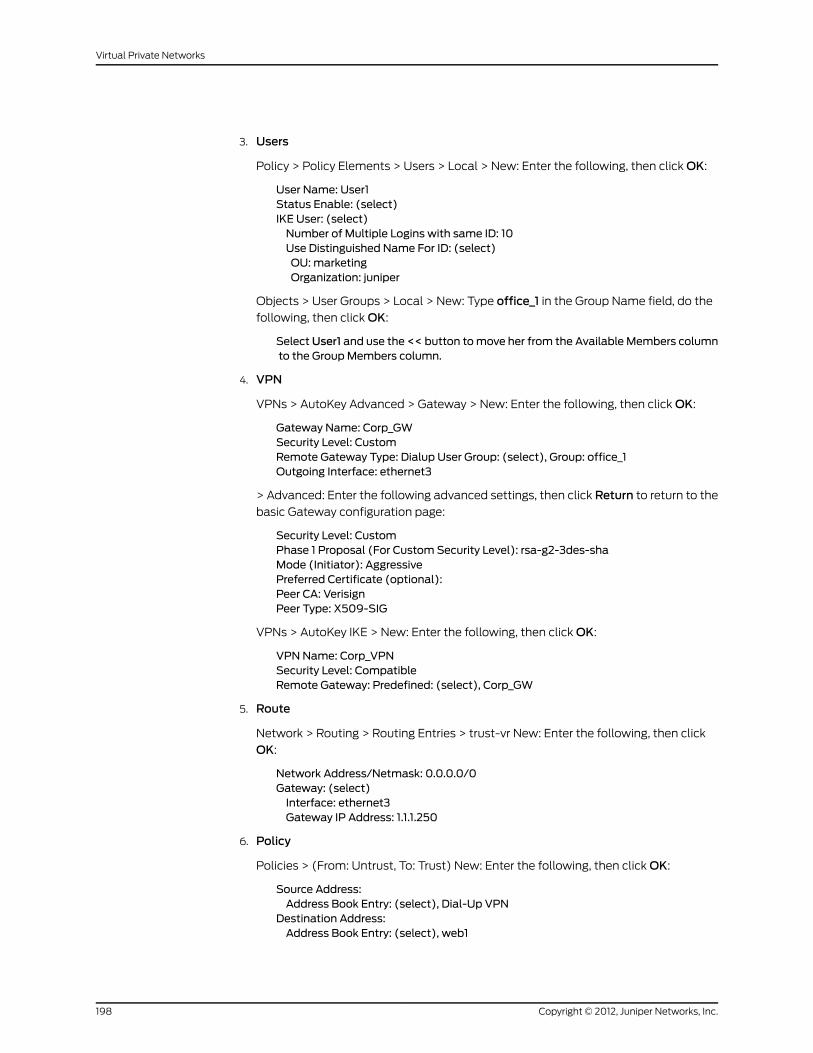
3. Users
Policy > Policy Elements > Users > Local > New: Enter the following, then click OK:
User Name: User1Status Enable: (select)IKE User: (select)Number of Multiple Logins with same ID: 10Use Distinguished Name For ID: (select)OU: marketingOrganization: juniper
Objects > User Groups > Local > New: Type office_1 in the Group Name field, do the
following, then click OK:
SelectUser1 and use the << button tomove her from the Available Members columnto the GroupMembers column.
4. VPN
VPNs > AutoKey Advanced > Gateway > New: Enter the following, then click OK:
Gateway Name: Corp_GWSecurity Level: CustomRemote Gateway Type: Dialup User Group: (select), Group: office_1Outgoing Interface: ethernet3
> Advanced: Enter the following advanced settings, then click Return to return to the
basic Gateway configuration page:
Security Level: CustomPhase 1 Proposal (For Custom Security Level): rsa-g2-3des-shaMode (Initiator): AggressivePreferred Certificate (optional):Peer CA: VerisignPeer Type: X509-SIG
VPNs > AutoKey IKE > New: Enter the following, then click OK:
VPNName: Corp_VPNSecurity Level: CompatibleRemote Gateway: Predefined: (select), Corp_GW
5. Route
Network > Routing > Routing Entries > trust-vr New: Enter the following, then click
OK:
Network Address/Netmask: 0.0.0.0/0Gateway: (select)Interface: ethernet3Gateway IP Address: 1.1.1.250
6. Policy
Policies > (From: Untrust, To: Trust) New: Enter the following, then click OK:
Source Address:Address Book Entry: (select), Dial-Up VPN
Destination Address:Address Book Entry: (select), web1
Copyright © 2012, Juniper Networks, Inc.198
Virtual Private Networks

Service: HTTPAction: TunnelTunnel VPN: Corp_VPNModify matching bidirectional VPN policy: (clear)Position at Top: (select)
CLI
1. Interfaces
set interface ethernet1 zone trustset interface ethernet1 ip 10.1.1.1/24set interface ethernet1 natset interface ethernet3 zone untrustset interface ethernet3 ip 1.1.1.1/24
2. Address
set address trust web1 10.1.1.5/32
3. Users
set user User1 ike-id asn1-dn wildcard o=juniper,ou=marketing share-limit 10set user-group office_1 user User1
4. VPN
set ike gateway Corp_GW dialup office_1 aggressive outgoing-interface ethernet3proposal rsa-g2-3des-shaset ike gateway Corp_GW cert peer-ca 1set ike gateway Corp_GW cert peer-cert-type x509-sigset vpn Corp_VPN gateway Corp_GW sec-level compatible
NOTE: The number 1 is the CA ID number. To discover the CA’s ID number,use the following command: get pki x509 list ca-cert.
5. Route
set vrouter trust-vr route 0.0.0.0/0 interface ethernet3 gateway 1.1.1.250
6. Policy
set policy top from untrust to trust “Dial-Up VPN” web1 http tunnel vpn Corp_VPNsave
NetScreen-Remote Security Policy Editor
1. Click Options > Secure > Specified Connections.
2. Click Add a new connection, and type web1 next to the new connection icon that
appears.
3. Configure the connection options:
Connection Security: SecureRemote Party Identity and AddressingID Type: IP Address, 10.1.1.5Protocol: Highlight All, typeHTTP, press the Tab key, and type 80.
199Copyright © 2012, Juniper Networks, Inc.
Chapter 5: Dialup Virtual Private Networks

Connect using Secure Gateway Tunnel: (select)ID Type: IP Address, 1.1.1.1
4. Click the PLUS symbol, located to the left of the web1 icon, to expand the connection
policy.
5. Click My Identity: Select the certificate that has o=netscreen,ou=marketing as
elements in its distinguished name from the Select Certificate drop-down list.
ID Type: SelectDistinguished Name from the drop-down list.
NOTE: This example assumes that you have already loaded a suitablecertificateon theNetScreen-Remoteclient. For informationabout loadingcertificates on the NetScreen-Remote, refer to the NetScreen-Remotedocumentation.
6. Click theSecurityPolicy icon, then selectAggressiveMode and clearEnable PerfectForward Secrecy (PFS).
7. Click the PLUS symbol, located to the left of the Security Policy icon, and then the
PLUS symbol to the left of Authentication (Phase 1) and Key Exchange (Phase 2) to
expand the policy further.
8. Click Authentication (Phase 1) > Proposal 1: Select the following Encryption and
Data Integrity Algorithms:
Authentication Method: RSA SignaturesEncrypt Alg: Triple DESHash Alg: SHA-1Key Group: Diffie-Hellman Group 2
9. Click Key Exchange (Phase 2) > Proposal 1: Select the following IPsec protocols:
Encapsulation Protocol (ESP): (select)Encrypt Alg: Triple DESHash Alg: SHA-1Encapsulation: Tunnel
10. Click Key Exchange (Phase 2) > Create NewProposal: Select the following IPsec
protocols:
Encapsulation Protocol (ESP): (select)Encrypt Alg: Triple DESHash Alg: MD5Encapsulation: Tunnel
11. Click Key Exchange (Phase 2) > Create NewProposal: Select the following IPsec
protocols:
Encapsulation Protocol (ESP): (select)Encrypt Alg: DESHash Alg: SHA-1Encapsulation: Tunnel
12. Click Key Exchange (Phase 2) > Create NewProposal: Select the following IPsec
protocols:
Copyright © 2012, Juniper Networks, Inc.200
Virtual Private Networks
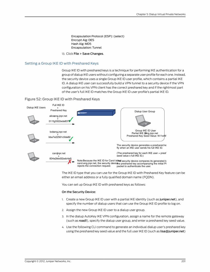
Encapsulation Protocol (ESP): (select)Encrypt Alg: DESHash Alg: MD5Encapsulation: Tunnel
13. Click File > Save Changes.
Setting a Group IKE IDwith Preshared Keys
Group IKE ID with preshared keys is a technique for performing IKE authentication for a
group of dialup IKE users without configuring a separate user profile for each one. Instead,
the security device uses a single Group IKE ID user profile, which contains a partial IKE
ID. A dialup IKE user can successfully build a VPN tunnel to a security device if the VPN
configuration on his VPN client has the correct preshared key and if the rightmost part
of the user’s full IKE ID matches the Group IKE ID user profile’s partial IKE ID.
Figure 52: Group IKE IDwith Preshared Keys
Group IKE ID UserPartial IKE ID:eng.jnpr.net
Preshared Key Seed Value: N11wWd2
Dialup User Group
Full IKE ID+
Preshared Key
alice.eng.jnpr.net+
011fg3322eda837c
bob.eng.jnpr.net+
bba7e22561c5da82
carol.jnpr.net+
834a2bbd32adc4e9Note:Because the IKE ID for Carol is notcarol.eng.jnpr.net, the security devicerejects the connection request.
Dialup IKE Users
The security device generates a preshared key on thefly when an IKE user sends his full IKE ID.
(The preshared key for each IKE user = preshared keyseed value x full IKE ID.)
The security device compares its generated key withthe preshared key accompanying the initial Phase 1packet to authenticate the user.
The IKE ID type that you can use for the Group IKE ID with Preshared Key feature can be
either an email address or a fully qualified domain name (FQDN).
You can set up Group IKE ID with preshared keys as follows:
On the Security Device:
1. Create a new Group IKE ID user with a partial IKE identity (such as juniper.net), and
specify the number of dialup users that can use the Group IKE ID profile to log on.
2. Assign the new Group IKE ID user to a dialup user group.
3. In the dialup AutoKey IKE VPN configuration, assign a name for the remote gateway
(such as road1), specify the dialup user group, and enter a preshared key seed value.
4. Use the following CLI command to generate an individual dialup user’s preshared key
using the preshared key seed value and the full user IKE ID (such as [email protected])
201Copyright © 2012, Juniper Networks, Inc.
Chapter 5: Dialup Virtual Private Networks

exec ike preshare-gen name_str usr_name_str (for example) exec ike preshare-genroad1 [email protected]
5. Record the preshared key for use when configuring the remote VPN client.
On the VPN Client:
Configure a VPN tunnel to the security device using aggressive mode for Phase 1
negotiations, and enter the preshared key that you previously generated on the security
device.
Thereafter, the security device can successfully authenticate each individual user whose
full IKE ID contains a section that matches the partial Group IKE ID user profile. For
example, if the Group IKE ID user has IKE identity juniper.net, any user with that domain
name in his IKE ID can initiate Phase 1 IKE negotiations in aggressive mode with the
security device. For example:[email protected],[email protected],[email protected] many such users can log on depends upon a maximum number of concurrent
sessions specified in the Group IKE ID user profile.
In this example, you create a new Group IKE ID user named User2. You configure it to
accept up to 10 Phase 1 negotiations concurrently from VPN clients with preshared keys
containing an IKE ID ending with the string juniper.net. The seed value for the preshared
key is jk930k. You name the dialup IKE user group office_2.
Figure 53: Group IKE ID (Preshared Keys)
VPN TunnelGroup IKE ID User Profile
User Name: User2User Group: office_2Simple ID:juniper.net
Trust Zoneethernet1, 10.1.1.1/24
NAT Mode
Outgoing InterfaceUntrust Zone
ethernet3, 1.1.1.1/24
Gateway 1.1.1.250
Dialup User withIKE ID:
Untrust Zone Trust Zone
Web110.1.1.5
Internet LAN
For both the Phase 1 and Phase 2 negotiations, you select the security level predefined
as “Compatible.” All the security zones are in the trust-vr routing domain.
WebUI
1. Interfaces
Network > Interfaces > Edit (for ethernet1): Enter the following, then click OK:
Zone Name: TrustStatic IP: (select this option when present)IP Address/Netmask: 10.1.1.1/24Select the following, then clickOK:Interface Mode: NAT
Network > Interfaces > Edit (for ethernet3): Enter the following, then click OK:
Zone Name: UntrustStatic IP: (select this option when present)IP Address/Netmask: 1.1.1.1/24
2. Address
Copyright © 2012, Juniper Networks, Inc.202
Virtual Private Networks

Policy > Policy Elements > Addresses > List > New : Enter the following, then click
OK:
Address Name: web1IP Address/Domain Name:IP/Netmask: (select), 10.1.1.5/32
Zone: Trust
3. Users
Policy > Policy Elements > Users > Local > New: Enter the following, then click OK:
User Name: User2Status: EnableIKE User: (select)Number of Multiple Logins with same ID: 10Simple Identity: (select)IKE Identity: juniper.net
Policy > Policy Elements > User Groups > Local > New: Type office_2 in the Group
Name field, do the following, then click OK:
SelectUser2anduse the<<button tomovehim from theAvailableMembers columnto the GroupMembers column.
4. VPN
NOTE: TheWebUI allows you to enter only a value for a preshared key,not a seed value fromwhich the security device derives a preshared key.To enter a preshared key seed value when configuring an IKE gateway,youmust use the CLI.
VPNs > AutoKey IKE > New: Enter the following, then click OK:
VPNName: Corp_VPNSecurity Level: CompatibleRemote Gateway: Predefined: (select), Corp_GW
5. Route
Network > Routing > Routing Entries > trust-vr New: Enter the following, then click
OK:
Network Address/Netmask: 0.0.0.0/0Gateway: (select)Interface: ethernet3Gateway IP Address: 1.1.1.250
6. Policy
Policies > (From: Untrust, To: Trust) New: Enter the following, then click OK:
Source Address:Address Book Entry: (select), Dial-Up VPN
Destination Address:Address Book Entry: (select), web1
Service: HTTPAction: Tunnel
203Copyright © 2012, Juniper Networks, Inc.
Chapter 5: Dialup Virtual Private Networks

Tunnel VPN: Corp_VPNModify matching bidirectional VPN policy: (clear)Position at Top: (select)
CLI
1. Interfaces
set interface ethernet1 zone trustset interface ethernet1 ip 10.1.1.1/24set interface ethernet1 natset interface ethernet3 zone untrustset interface ethernet3 ip 1.1.1.1/24
2. Address
set address trust web1 10.1.1.5/32
3. Users
set user User2 ike-id u-fqdn juniper.net share-limit 10set user-group office_2 user User2
4. VPN
set ike gateway Corp_GW dialup office_2 aggressive seed-preshare jk930k sec-levelcompatibleset vpn Corp_VPN gateway Corp_GW sec-level compatible
5. Route
set vrouter trust-vr route 0.0.0.0/0 interface ethernet3 gateway 1.1.1.250
6. Policy
set policy top from untrust to trust “Dial-Up VPN” web1 http tunnel vpn Corp_VPNsave
Obtaining the Preshared Key
You can only obtain the preshared key by using the following CLI command:
exec ike preshare-gen name_str usr_name_str
The preshared key, based on the preshared key seed value jk930k (as specified in the
configuration for the remote gateway named Corp_GW), and the full identity of individual
user [email protected] is 11ccce1d396f8f29ffa93d11257f691af96916f2.
NetScreen-Remote Security Policy Editor
1. Click Options > Secure > Specified Connections.
2. Click Add a new connection, and type web1 next to the new connection icon that
appears.
3. Configure the connection options:
Connection Security: SecureRemote Party Identity and AddressingID Type: IP Address, 10.1.1.5Protocol: Highlight All, typeHTTP, press the Tab key, and type 80.
Copyright © 2012, Juniper Networks, Inc.204
Virtual Private Networks

Connect using Secure Gateway Tunnel: (select)ID Type: IP Address, 1.1.1.1
4. Click the PLUS symbol, located to the left of the web1 icon, to expand the connection
policy.
5. Click theSecurityPolicy icon, then selectAggressiveMode and clearEnable PerfectForward Secrecy (PFS).
6. Click My Identity: Click Pre-shared Key > Enter Key: Type
11ccce1d396f8f29ffa93d11257f691af96916f2, then click OK.
ID Type: (select E-mail Address), and type [email protected].
7. Click the PLUS symbol, located to the left of the Security Policy icon, then click the
PLUS symbol to the left of Authentication (Phase 1) and Key Exchange (Phase 2) to
expand the policy further.
8. Click Authentication (Phase 1) > Proposal 1: Select the following Encryption and
Data Integrity Algorithms:
Authentication Method: Pre-Shared KeyEncrypt Alg: Triple DESHash Alg: SHA-1Key Group: Diffie-Hellman Group 2
9. Click Authentication (Phase 1) > Create NewProposal: Select the following IPsec
protocols:
Authentication Method: Pre-Shared KeyEncrypt Alg: Triple DESHash Alg: MD5Key Group: Diffie-Hellman Group 2
10. Click Authentication (Phase 1) > Create NewProposal: Select the following IPsec
protocols:
Authentication Method: Pre-Shared KeyEncrypt Alg: DESHash Alg: SHA-1Key Group: Diffie-Hellman Group 2
11. Click Authentication (Phase 1) > Create NewProposal: Select the following IPsec
protocols:
Authentication Method: Pre-Shared KeyEncrypt Alg: DESHash Alg: MD5Key Group: Diffie-Hellman Group 2
12. Click Key Exchange (Phase 2) > Proposal 1: Select the following IPsec protocols:
Encapsulation Protocol (ESP): (select)Encrypt Alg: Triple DESHash Alg: SHA-1Encapsulation: Tunnel
13. Click Key Exchange (Phase 2) > Create NewProposal: Select the following IPsec
protocols:
205Copyright © 2012, Juniper Networks, Inc.
Chapter 5: Dialup Virtual Private Networks

Encapsulation Protocol (ESP): (select)Encrypt Alg: Triple DESHash Alg: MD5Encapsulation: Tunnel
14. Click Key Exchange (Phase 2) > Create NewProposal: Select the following IPsec
protocols:
Encapsulation Protocol (ESP): (select)Encrypt Alg: DESHash Alg: SHA-1Encapsulation: Tunnel
15. Click Key Exchange (Phase 2) > Create NewProposal: Select the following IPsec
protocols:
Encapsulation Protocol (ESP): (select)Encrypt Alg: DESHash Alg: MD5Encapsulation: Tunnel
16. Click File > Save Changes.
Shared IKE ID
The Shared IKE ID feature facilitates the deployment of a large number of dialup users.
With this feature, the security device authenticates multiple dialup VPN users using a
single Group IKE ID and preshared key. Thus, it provides IPsec protection for large remote
user groups through a common VPN configuration. In this release of ScreenOS, Shared
IKE ID is also supported for IKEv2.
This feature is similar to the Group IKE ID with preshared keys feature, with the following
differences:
• With the Group IKE ID feature, the IKE ID can be an email address or a fully qualified
domain name (FQDN). For this feature, the IKE ID must be an email address.
• Instead of using the preshared key seed value and the full user IKE ID to generate a
preshared key for each user, you specify a single preshared key for all users in the group.
• You must use XAuth (for IKEv1) or EAP (for IKEv2) to authenticate the individual users.
To set up a Shared IKE ID and preshared key on the security device:
1. Create a new Group IKE ID user, and specify how many dialup users can use the Group
IKE ID to log on. For this feature, use an email address as the IKE ID.
2. Assign the new Group IKE ID to a dialup user group.
3. In the dialup-to-LAN AutoKey IKE VPN configuration, create a Shared IKE ID gateway.
4. Define the XAuth users and enable XAuth on the remote IKE gateway.
On the VPN Client:
Copyright © 2012, Juniper Networks, Inc.206
Virtual Private Networks

Configure a VPN tunnel to the security device using aggressive mode for Phase 1
negotiations, and enter the preshared key that you previously defined on the security
device.Thereafter, the security device authenticates each remote user as follows:
During Phase 1 negotiations, the security device first authenticates the VPN client by
matching the IKE ID and preshared key that the client sends with the IKE ID and preshared
key on the security device. If there is a match, then the security device uses XAuth to
authenticate the individual user. It sends a login prompt to the user at the remote site
between Phase 1 and Phase 2 IKE negotiations. If the remote user successfully logs on
with the correct username and password, Phase 2 negotiations begin.
In this example, you create a new Group IKE ID user named Remote_Sales. It accepts up
to 250 Phase 1 negotiations concurrently from VPN clients with the same preshared key
(abcd1234). You name the dialup IKE user groupR_S. In addition, you configure two XAuth
users, Joe and Mike.
For both the Phase 1 and Phase 2 negotiations, you select the security level predefined
as Compatible. All the security zones are in the trust-vr routing domain.
Figure 54: Shared IKE ID (Preshared Keys)
VPN Tunnels
Shared IKE ID User ProfileUser Name: Remote_Sales
User Group: R_SSimple ID: [email protected]
ethernet1, 10.1.1.1/24NAT Mode
Outgoing Interfaceethernet3, 1.1.1.1/24
Dialup User withIKE ID: [email protected]
XAuth password: 5678
Untrust ZoneTrust Zone
Web110.1.1.5
Dialup User withIKE ID: [email protected]
XAuth password: 1234
LAN
WebUI
1. Interfaces
Network > Interfaces > Edit (for ethernet1): Enter the following, then click Apply:
Zone Name: TrustStatic IP: (select this option when present)IP Address/Netmask: 10.1.1.1/24Select the following, then clickOK:Interface Mode: NAT
Network > Interfaces > Edit (for ethernet3): Enter the following, then click OK:
Zone Name: UntrustStatic IP: (select this option when present)IP Address/Netmask: 1.1.1.1/24
2. Address
Policy > Policy Elements > Addresses > List > New: Enter the following, then clickOK:
Address Name: web1IP Address/Domain Name:
207Copyright © 2012, Juniper Networks, Inc.
Chapter 5: Dialup Virtual Private Networks

IP/Netmask: (select), 10.1.1.5/32Zone: Trust
3. Users
Policy > Policy Elements > Users > Local > New: Enter the following, then click OK:
User Name: Remote_SalesStatus: EnableIKE User: (select)Number of Multiple Logins with same ID: 250Simple Identity: (select)IKE Identity: [email protected]
Policy > Policy Elements > User Groups > Local > New: Type R_S in the Group Name
field, do the following, then click OK:
SelectRemote_salesanduse the<<button tomovehim fromtheAvailableMemberscolumn to the GroupMembers column.
Policy > Policy Elements > Users > Local > New: Enter the following, then click OK:
User Name: JoeStatus: EnableXAuth User: (select)Password: 1234Confirm Password: 1234
Policy > Policy Elements > Users > Local > New: Enter the following, then click OK:
User Name: MikeStatus: EnableXAuth User: (select)Password: 5678Confirm Password: 5678
4. VPN
VPNs > AutoKey Advanced > Gateway > New: Enter the following, then click OK:
Gateway Name: sales_gatewaySecurity Level: Compatible (select)Remote Gateway Type: Dialup Group (select), R_SPreshared Key: abcd1234Outgoing Interface: ethernet3
> Advanced: Enter the following, then click Return to return to the base Gateway
configuration page:
Enable XAuth: (select)Local Authentication: (select)Allow Any: (select)
VPNs > AutoKey IKE > New: Enter the following, then click OK:
VPNName: Sales_VPNSecurity Level: CompatibleRemote Gateway: Predefined: (select) sales_gateway
> Advanced: Enter the following advanced settings, then click Return to return to the
basic AutoKey IKE configuration page:
Copyright © 2012, Juniper Networks, Inc.208
Virtual Private Networks

Bind to: Tunnel Zone, Untrust-Tun
5. Route
Network > Routing > Routing Entries > trust-vr New: Enter the following, then click
OK:
Network Address / Netmask: 0.0.0.0/0Gateway: (select)Interface: ethernet3Gateway IP Address: 1.1.1.250
6. Policy
Policies > (From: Untrust, To: Trust) New: Enter the following, then click OK:
Source Address:Address Book Entry: (select), Dial-Up VPN
Destination Address:Address Book Entry: (select), web1
Service: HTTPAction: TunnelTunnel VPN: Sales_VPNModify matching bidirectional VPN policy: (clear)Position at Top: (select)
CLI
1. Interfaces
set interface ethernet1 zone trustset interface ethernet1 ip 10.1.1.1/24set interface ethernet1 natset interface ethernet3 zone untrustset interface ethernet3 ip 1.1.1.1/24
2. Address
set address trust web1 10.1.1.5/32
3. Users
set user Remote_Sales ike-id [email protected] share-limit 250set user-group R_S user Remote_Salesset user Joe password 1234set user Joe type xauthset user Mike password 5678set user Mike type xauth
4. VPN
set ike gateway sales_gateway dialup R_S aggressive outgoing-interface ethernet3preshare abcd1234 sec-level compatibleset ike gateway sales_gateway xauthset vpn sales_vpn gateway sales_gateway sec-level compatibleset vpn sales_vpn bind zone untrust-tun
5. Route
set route 0.0.0.0/0 interface ethernet3 gateway 1.1.1.250
209Copyright © 2012, Juniper Networks, Inc.
Chapter 5: Dialup Virtual Private Networks

6. Policy
set policy top from untrust to trust “Dial-Up VPN” web1 http tunnel vpn sales_vpnsave
NetScreen-Remote Security Policy Editor
This example shows the configuration for the user named Joe.
1. Click Options > Secure > Specified Connections.
2. Click Add a new connection, and type web1 next to the new connection icon that
appears.
3. Configure the connection options:
Connection Security: SecureRemote Party ID Type: IP AddressIP Address: 10.1.1.5Connect using Secure Gateway Tunnel: (select)ID Type: IP Address; 1.1.1.1
4. Click the PLUS symbol, located to the left of the web1 icon, to expand the connection
policy.
5. Click theSecurityPolicy icon, then selectAggressiveMode and clearEnable PerfectForward Secrecy (PFS).
6. Click My Identity: Click Pre-shared Key > Enter Key: Type abcd1234, then click OK.
ID Type: (select E-mail Address), and type [email protected].
7. Click the PLUS symbol, located to the left of the Security Policy icon, then click the
PLUS symbol to the left of Authentication (Phase 1) and Key Exchange (Phase 2) to
expand the policy further.
8. Click Authentication (Phase 1) > Proposal 1: Select the following Encryption and
Data Integrity Algorithms:
Authentication Method: Pre-Shared Key; Extended AuthenticationEncrypt Alg: Triple DESHash Alg: SHA-1Key Group: Diffie-Hellman Group 2
9. Click Authentication (Phase 1) > Create NewProposal: Select the following IPsec
protocols:
Authentication Method: Pre-Shared Key; Extended AuthenticationEncrypt Alg: Triple DESHash Alg: MD5Key Group: Diffie-Hellman Group 2
10. Click Authentication (Phase 1) > Create NewProposal: Select the following IPsec
protocols:
Authentication Method: Pre-Shared Key; Extended AuthenticationEncrypt Alg: DESHash Alg: SHA-1Key Group: Diffie-Hellman Group 2
Copyright © 2012, Juniper Networks, Inc.210
Virtual Private Networks

11. Click Authentication (Phase 1) > Create NewProposal: Select the following IPsec
protocols:
Authentication Method: Pre-Shared Key; Extended AuthenticationEncrypt Alg: DESHash Alg: MD5Key Group: Diffie-Hellman Group 2
12. Click Key Exchange (Phase 2) > Proposal 1: Select the following IPsec protocols:
Encapsulation Protocol (ESP): (select)Encrypt Alg: Triple DESHash Alg: SHA-1Encapsulation: Tunnel
13. Click Key Exchange (Phase 2) > Create NewProposal: Select the following IPsec
protocols:
Encapsulation Protocol (ESP): (select)Encrypt Alg: Triple DESHash Alg: MD5Encapsulation: Tunnel
14. Click Key Exchange (Phase 2) > Create NewProposal: Select the following IPsec
protocols:
Encapsulation Protocol (ESP): (select)Encrypt Alg: DESHash Alg: SHA-1Encapsulation: Tunnel
15. Click Key Exchange (Phase 2) > Create NewProposal: Select the following IPsec
protocols:
Encapsulation Protocol (ESP): (select)Encrypt Alg: DESHash Alg: MD5Encapsulation: Tunnel
16. Click File > Save Changes.
211Copyright © 2012, Juniper Networks, Inc.
Chapter 5: Dialup Virtual Private Networks

Copyright © 2012, Juniper Networks, Inc.212
Virtual Private Networks

CHAPTER 6
Layer 2 Tunneling Protocol
This chapter provides an introduction to Layer 2 Tunneling Protocol (L2TP), its use alone
and with IPsec support, and some configuration examples for L2TP and L2TP-over-IPsec.
It contains the following sections:
• Introduction to L2TP on page 213
• Packet Encapsulation and Decapsulation on page 215
• Setting L2TP Parameters on page 217
• L2TP and L2TP-over-IPsec on page 219
Introduction to L2TP
Layer 2 Tunneling Protocol (L2TP) provides a way for a dialup user to make a virtual
Point-to-Point Protocol (PPP) connection to an L2TP network server (LNS), which can
be a security device. L2TP sends PPP frames through a tunnel between an L2TP access
concentrator (LAC) and the LNS.
Originally, L2TP was designed so that a LAC residing at an ISP site tunneled to an LNS
at either another ISP or corporate site. The L2TP tunnel did not extend completely to the
dialup user’s computer, but only to the LAC at the dialup user’s local ISP. (This is
sometimes referred to as a compulsory L2TP configuration.)
A NetScreen-Remote client on Windows 2000 or Windows NT, or a Windows 2000
client by itself, can act as a LAC. The L2TP tunnel can extend directly to the dialup user’s
computer, thus providing end-to-end tunneling. (This approach is sometimes referred
to as a voluntary L2TP configuration.)
Figure 55: L2TP Tunnel Between VPN Client (LAC) and Security Device (LNS)
NetScreen-Remoteor Windows 2000
(LAC)ISP Internet
L2TP Tunnel(forwarding PPP sessions
from LAC to LNS)
Security Device(LNS)
CorporateLAN
213Copyright © 2012, Juniper Networks, Inc.

Because the PPP link extends from the dialup user across the Internet to the security
device (LNS), it is the security device, not the ISP, that assigns the client its IP address,
DNS and WINS servers addresses, and authenticates the user, either from the local
database or from an external auth server (RADIUS, SecurID, or LDAP).
In fact, the client receives two IP addresses—one for its physical connection to the ISP,
and a logical one from the LNS. When the client contacts its ISP, perhaps using PPP, the
ISP makes IP and DNS assignments, and authenticates the client. This allows users to
connect to the Internet with a public IP address, which becomes the outer IP address of
the L2TP tunnel.
Figure 56: IP and DNS Assignments from ISP
First, the ISP assigns the clienta public IP address and DNSserver addresses.
IP Address: 5.5.5.5DNS: 6.6.6.6, 7.7.7.7
ISP
Then, when the L2TP tunnel forwards the encapsulated PPP frames to the security
device, the security device assigns the client an IP address, and DNS and WINS settings.
The IP address can be from the set of private addresses not used on the Internet. This
address becomes the inner IP address of the L2TP tunnel.
Figure 57: IP and DNS Assignments from LNS
InternetSecurity Device
(LNS)
CorporateLAN10.1.1.0/24
Second, the security device—acting as anLNS—assigns the client a private (logical) IPaddress, and DNS and WINS server addresses.
IP Address Pool10.10.1.1 – 10.10.1.254
IP Address: 10.10.1.161DNS: 10.1.1.10, 1.2.2.10WINS: 10.1.1.48, 10.1.1.49
NOTE: The IP addresses assigned to the L2TP client must be in a differentsubnet from the IP addresses in the corporate LAN.
The current version of ScreenOS provides the following L2TP support:
Copyright © 2012, Juniper Networks, Inc.214
Virtual Private Networks

• L2TP tunnels originating from a host running Windows 2000
NOTE: By default, Windows 2000 performs L2TP-over-IPsec. To force itto use L2TP only, youmust navigate to the ProhibitIPSec key in the registryand change0 (L2TP-over-IPsec) to 1 (L2TPonly). (Before performing this,Juniper Networks recommends that you back up your registry.) Click Start> Run: Type regedit. Double-clickHKEY_LOCAL_MACHINE > System >CurrentControlSet > Services > RasMan > Parameters. Double-clickProhibitIPSec: Type 1 in the Value data field, selectHexadecimal as thebase value, then clickOK. Reboot. (If you do not find such an entry in theregistry, seeMicrosoftWindowsdocumentation for informationabouthowto create one.)
• Combination of L2TP and IPsec in transport mode (L2TP-over-IPsec)
• For NetScreen-Remote: L2TP-over-IPsec with main mode negotiations using
certificates, and aggressive mode using either a preshared key or certificates
• For Windows 2000: L2TP-over-IPsec with main mode negotiations using certificates
• Outgoing dialup policy for L2TP and L2TP-over-IPsec tunnels (An outgoing dialup
policy can be paired with an incoming policy to provide a bidirectional tunnel.)
• User authentication using either the Password Authentication Protocol (PAP) and
Challenge Handshake Authentication Protocol (CHAP) from the local database or an
external auth server (RADIUS, SecurID, or LDAP)
NOTE: The local database and RADIUS servers support both PAP andCHAP. SecurID and LDAP servers support PAP only.
• The assignment of dialup users’ IP address, Domain Name System (DNS) servers, and
Windows Internet Naming Service (WINS) servers from either the local database or a
RADIUS server
• L2TP tunnels and L2TP-over-IPsec tunnels for the root system and virtual systems
NOTE: To use L2TP, the security devicemust be operating at Layer 3, withsecurity zone interfaces in NAT or routemode. When the security device isoperating at Layer 2, with security zone interfaces in transparentmode, noL2TP-relatedmaterial appears in theWebUI, and L2TP-related CLIcommands elicit error messages.
Packet Encapsulation and Decapsulation
L2TP employs encapsulation of packets as the means for transporting PPP frames from
the LAC to the LNS. Before looking at specific examples for setting up L2TP and
215Copyright © 2012, Juniper Networks, Inc.
Chapter 6: Layer 2 Tunneling Protocol

L2TP-over-IPsec, an overview of the encapsulation and decapsulation involved in the
L2TP process is presented.
Encapsulation
When a dialup user on an IP network sends data over an L2TP tunnel, the LAC
encapsulates the IP packet within a series of Layer 2 frames, Layer 3 packets, and Layer 4
segments. Assuming that the dialup user connects to the local ISP over a PPP link, the
encapsulation proceeds as shown in Figure 58 on page 216.
Figure 58: L2TP Packet Encapsulation
1. The data is placed in an IP payload.
2. The IP packet is encapsulated in a PPP frame.
3. The PPP frame is encapsulated in an L2TP frame.
4. The L2TP frame is encapsulated in a UDP segment.
5. The UDP segment is encapsulated in an IP packet.
6. The IP packet is encapsulated in a PPP frame to make the physical connection between
the dialup user and the ISP.
Decapsulation
When the LAC initiates the PPP link to the ISP, the decapsulation and forwarding of the
nested contents proceed as shown in Figure 59 on page 217.
Copyright © 2012, Juniper Networks, Inc.216
Virtual Private Networks

Figure 59: L2TP Packet Decapsulation
1. The ISP completes the PPP link and assigns the user’s computer an IP address.
Inside the PPP payload is an IP packet.
2. The ISP removes the PPP header and forwards the IP packet to the LNS.
3. The LNS removes the IP header.
Inside the IP payload is a UDP segment specifying port 1701, the port number reserved
for L2TP.
4. The LNS removes the UDP header.
Inside the UDP payload is an L2TP frame.
5. The LNS processes the L2TP frame, using the tunnel ID and call ID in the L2TP header
to identify the specific L2TP tunnel. The LNS then removes the L2TP header.
Inside the L2TP payload is a PPP frame.
6. The LNS processes the PPP frame, assigning the user’s computer a logical IP address.
Inside the PPP payload is an IP packet.
7. The LNS routes the IP packet to its ultimate destination, where the IP header is removed
and the data in the IP packet is extracted.
Setting L2TP Parameters
The LNS uses L2TP to provide the PPP settings for a dialup user, which typically come
from an ISP. These settings are as follows:
• IP address – The security device selects an address from a pool of IP addresses and
assigns it to the dialup user’s computer. The selection process operates cyclically
through the IP address pool; that is, in a pool from 10.10.1.1 to 10.10.1.3, the addresses
217Copyright © 2012, Juniper Networks, Inc.
Chapter 6: Layer 2 Tunneling Protocol

are selected in the following cycle: 10.10.1.1 – 10.10.1.2 – 10.10.1.3 – 10.10.1.1 – 10.10.1.2
…
• DNS primary and secondary server IP addresses – The security device provides these
addresses to the dialup user’s computer.
• WINS primary and secondary server IP addresses – The security device also provides
these addresses to the dialup user’s computer.
The LNS also authenticates the user through a username and password. You can enter
the user in the local database or in an external auth server (RADIUS, SecurID, or LDAP).
NOTE: The RADIUS or SecurID server that you use for authenticating L2TPuserscanbe thesameserver youuse fornetworkusers, or it canbeadifferentserver.
In addition, you can specify one of the following schemes for the PPP authentication:
• Challenge Handshake Authentication Protocol (CHAP), in which the security device
sends a challenge (encryption key) to the dialup user after he or she makes a PPP link
request, and the user encrypts his or her login name and password with the key. The
local database and RADIUS servers support CHAP.
• Password Authentication Protocol (PAP), which sends the dialup user’s password in
the clear along with the PPP link request. The local database and RADIUS, SecurID,
and LDAP servers support PAP.
• “ANY”, meaning that the security device negotiates CHAP, and then if that fails, PAP.
You can apply to dialup users and dialup user groups the default L2TP parameters that
you configure on the L2TP Default Configuration page (VPNs > L2TP > Default Settings)
or with the set l2tp default command. You can also apply L2TP parameters that you
configure specifically for L2TP users on the User Configuration page (Users > Users >
Local > New) or with thesetusername_str remote-settingscommand. The user-specific
L2TP settings supersede the default L2TP settings.
As shown in Figure 60 on page 219, you define an IP address pool with addresses ranging
from 10.1.3.40 to 10.1.3.100. You specify DNS server IP addresses 1.1.1.2 (primary) and
1.1.1.3 (secondary). The security device performs PPP authentication using CHAP.
NOTE: You specify the auth server on a per-L2TP tunnel basis.
Copyright © 2012, Juniper Networks, Inc.218
Virtual Private Networks

Figure 60: IP Pool and L2TP Default Settings
WebUI
1. IP Pool
Objects > IP Pools > New: Enter the following, then click OK:
IP Pool Name: SutroStart IP: 10.1.3.40End IP: 10.1.3.100
2. Default L2TP Settings
VPNs > L2TP > Default Settings: Enter the following, then click Apply:
IP Pool Name: SutroPPP Authentication: CHAPDNS Primary Server IP: 1.1.1.2DNS Secondary Server IP: 1.1.1.3WINS Primary Server IP: 0.0.0.0WINS Secondary Server IP: 0.0.0.0
CLI
1. IP Pool
set ippool sutro 10.1.3.40 10.1.3.100
2. Default L2TP Settings
set l2tp default ippool sutroset l2tp default ppp-auth chapset l2tp default dns1 1.1.1.2set l2tp default dns2 1.1.1.3save
L2TP and L2TP-over-IPsec
Although the dialup user can be authenticated using CHAP or PAP, an L2TP tunnel is not
encrypted, and therefore is not a true VPN tunnel. The purpose of L2TP is simply to permit
the administrator of the local security device to assign IP addresses to remote dialup
users. These addresses can then be referenced in policies.
To encrypt an L2TP tunnel, you need to apply an encryption scheme to the L2TP tunnel.
Because L2TP assumes that the network between the LAC and the LNS is IP, you can
employ IPsec to provide encryption. This combination is called L2TP-over-IPsec.
219Copyright © 2012, Juniper Networks, Inc.
Chapter 6: Layer 2 Tunneling Protocol

L2TP-over-IPsec requires setting up both an L2TP tunnel and an IPsec tunnel with the
same endpoints, and then linking them together in a policy. L2TP-over-IPsec requires
that the IPsec tunnel be in transport mode so that the tunnel endpoint addresses remain
in the clear. (For information about transport and tunnel mode, see “Modes” on page 5.)
You can create an L2TP tunnel between a security device and a host running Windows
2000 if you change the registry settings. (For instructions on how to change the registry,
see the note in “Introduction to L2TP” on page 213 .)
You can create an L2TP-over-IPsec tunnel between a security device and either of the
following VPN clients:
• A host running NetScreen-Remote on a Windows 2000 or Windows NT operating
system
• A host running Windows 2000 (without NetScreen-Remote)
NOTE: To provide authentication when usingWIndows 2000withoutNetScreen-Remote, youmust use certificates.
Configuring L2TP
In this example, as illustrated in Figure 61 on page 221, you create a dialup user group
called “fs” (for “field-sales”) and configure an L2TP tunnel called “sales_corp,” using
ethernet3 (Untrust zone) as the outgoing interface for the L2TP tunnel. The security
device applies the following default L2TP tunnel settings to the dialup user group:
• The L2TP users are authenticated through the local database.
• PPP authentication uses CHAP.
• The range of addresses in the IP pool (named “global”) is from 10.10.2.100 to 10.10.2.180.
• The DNS servers are 1.1.1.2 (primary) and 1.1.1.3 (secondary).
NOTE: An L2TP-only configuration is not secure. It is recommended onlyfor debugging purposes.
The addresses in the L2TP IP pool must be in a different subnet than theaddresses in the corporate network.
Copyright © 2012, Juniper Networks, Inc.220
Virtual Private Networks

Figure 61: Configuring L2TP
Auth/L2TP DialupUsers Group: fs
Adam
BettyBetty
Carol
NetScreen-RemoteClients
CorporateNetwork
IP Pool: global10.10.2.100 –10.10.2.180
Outgoing Interfaceethernet3, 1.1.1.1/24
ethernet1,10.1.1.1/24
Trust Zone
Internet
DNS1: 1.1.1.2DNS1: 1.1.1.2
DNS2: 1.1.1.3DNS2: 1.1.1.3
DialupZone
L2TP Tunnel:sales_corp
The remote L2TP clients are on Windows 2000 operating systems. For information about
how to configure L2TP on the remote clients, refer to your Windows 2000 documentation.
Only the configuration for the security device end of the L2TP tunnel is provided below.
WebUI
1. Interfaces
Network > Interfaces > Edit (for ethernet1): Enter the following, then click Apply:
Zone Name: TrustStatic IP: (select this option when present)IP Address/Netmask: 10.1.1.1/24
Select the following, then click OK:
Interface Mode: NAT
Network > Interfaces > Edit (for ethernet3): Enter the following, then click OK:
Zone Name: UntrustStatic IP: (select this option when present)IP Address/Netmask: 1.1.1.1/24
2. L2TP Users
Objects > Users > Local > New: Enter the following, then click OK:
User Name: AdamStatus: EnableL2TP User: (select)User Password: AJbioJ15Confirm Password: AJbioJ15
Objects > Users > Local > New: Enter the following, then click OK:
User Name: BettyStatus: EnableL2TP User: (select)User Password: BviPsoJ1Confirm Password: BviPsoJ1
Objects > Users > Local > New: Enter the following, then click OK:
221Copyright © 2012, Juniper Networks, Inc.
Chapter 6: Layer 2 Tunneling Protocol

User Name: CarolStatus: EnableL2TP User: (select)User Password: Cs10kdD3Confirm Password: Cs10kdD3
3. L2TP User Group
Objects > User > Local Groups> New: Type fs in the Group Name field, do the following,
then click OK:
SelectAdamand use the<<button to move him from the Available Members column
to the Group Members column.
Select Betty and use the << button to move her from the Available Members column
to the Group Members column.
Select Carol and use the << button to move her from the Available Members column
to the Group Members column.
4. Default L2TP Settings
Objects > IP Pools > New: Enter the following, then click OK:
IP Pool Name: globalStart IP: 10.10.2.100End IP: 10.10.2.180
VPNs > L2TP > Default Settings: Enter the following, then click OK:
IP Pool Name: globalPPP Authentication: CHAPDNS Primary Server IP: 1.1.1.2DNS Secondary Server IP: 1.1.1.3WINS Primary Server IP: 0.0.0.0WINS Secondary Server IP: 0.0.0.0
5. L2TP Tunnel
VPNs > L2TP > Tunnel > New: Enter the following, then click OK:
Name: sales_corpUse Custom Settings: (select)Authentication Server: LocalDialup Group: Local Dialup Group - fsOutgoing Interface: ethernet3Peer IP: 0.0.0.0Host Name (optional): Enter the name of the computer acting as the LAC.Secret (optional): Enter a secret shared between the LAC and the LNS.Keep Alive: 60
Peer IP: Because the peer’s ISP dynamically assigns it an IP address, you would enter
0.0.0.0 in the above example.
LAC: To find the name of a computer running Windows 2000, do the following: Click
Start>Settings>ControlPanel>System. The System Properties dialog box appears.
Click the Network Identification tab, and see entry following Full computer name.
To add a secret to the LAC for authenticating the L2TP tunnel, you must modify the
Windows 2000 registry as follows:
Copyright © 2012, Juniper Networks, Inc.222
Virtual Private Networks
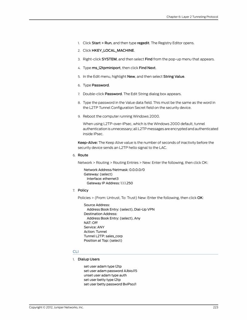
1. Click Start > Run, and then type regedit. The Registry Editor opens.
2. Click HKEY_LOCAL_MACHINE.
3. Right-click SYSTEM, and then select Find from the pop-up menu that appears.
4. Type ms_l2tpminiport, then click Find Next.
5. In the Edit menu, highlight New, and then select String Value.
6. Type Password.
7. Double-click Password. The Edit String dialog box appears.
8. Type the password in the Value data field. This must be the same as the word in
the L2TP Tunnel Configuration Secret field on the security device.
9. Reboot the computer running Windows 2000.
When using L2TP-over-IPsec, which is the Windows 2000 default, tunnel
authentication is unnecessary; all L2TP messages are encrypted and authenticated
inside IPsec.
Keep-Alive: The Keep Alive value is the number of seconds of inactivity before the
security device sends an L2TP hello signal to the LAC.
6. Route
Network > Routing > Routing Entries > New: Enter the following, then click OK:
Network Address/Netmask: 0.0.0.0/0Gateway: (select)Interface: ethernet3Gateway IP Address: 1.1.1.250
7. Policy
Policies > (From: Untrust, To: Trust) New: Enter the following, then click OK:
Source Address:Address Book Entry: (select), Dial-Up VPN
Destination Address:Address Book Entry: (select), Any
NAT: OffService: ANYAction: TunnelTunnel L2TP: sales_corpPosition at Top: (select)
CLI
1. Dialup Users
set user adam type l2tpset user adam password AJbioJ15unset user adam type authset user betty type l2tpset user betty password BviPsoJ1
223Copyright © 2012, Juniper Networks, Inc.
Chapter 6: Layer 2 Tunneling Protocol

unset user betty type authset user carol type l2tpset user carol password Cs10kdD3unset user carol type auth
NOTE: Defining a password for a user automatically classifies the user asan auth user. Therefore, to define the user type strictly as L2TP, youmustunset the auth user type.
2. L2TP User Group
set user-group fs location localset user-group fs user adamset user-group fs user bettyset user-group fs user carol
3. Default L2TP Settings
set ippool global 10.10.2.100 10.10.2.180set l2tp default ippool globalset l2tp default auth server Localset l2tp default ppp-auth chapset l2tp default dns1 1.1.1.2set l2tp default dns2 1.1.1.3
4. L2TP Tunnel
set l2tp sales_corp outgoing-interface ethernet3set l2tp sales_corp auth server Local user-group fs
5. Route
set vrouter trust-vr route 0.0.0.0/0 interface ethernet3 gateway 1.1.1.250
6. Policy
set policy top from untrust to trust “Dial-Up VPN” any tunnel l2tp sales_corpsave
Configuring L2TP-over-IPsec
This example uses the same L2TP tunnel created in the previous example (“Configuring
L2TP” on page 220). Additionally, you overlay an IPsec tunnel onto the L2TP tunnel to
provide encryption. The IPsec tunnel negotiates Phase 1 in Aggressive Mode using a
previously loaded RSA certificate, 3DES encryption and SHA-1 authentication. The
certificate authority (CA) is Verisign. (For information about obtaining and loading
certificates, see “Public Key Cryptography” on page 35.) The Phase 2 negotiation uses
the security level predefined as “Compatible” for Phase 2 proposals. The IPsec tunnel is
in transport mode.
The predefined Trust zone and the user-defined Dialup zone are in the trust-vr routing
domain. The interfaces for the Dialup and Trust zones are ethernet2 (1.3.3.1/24) and
ethernet1 (10.1.1.1/24), respectively. The Trust zone is in NAT mode.
Copyright © 2012, Juniper Networks, Inc.224
Virtual Private Networks

The dialup users Adam, Betty, and Carol use NetScreen-Remote clients on a Windows
2000 operating system. The NetScreen-Remote configuration for dialup user Adam is
also included below. (The NetScreen-Remote configuration for the other two dialup
users is the same as that for Adam.)
NOTE: To configure an L2TP-over-IPsec tunnel forWindows 2000 (withoutNetScreen-Remote), the Phase 1 negotiationsmust be in mainmode andthe IKE ID typemust be ASN1-DN.
Figure 62: Configuring L2TP-over-IPsec
IKE-L2TPDialup User Group: fs
Adam
Carol
NetScreen-Remote Clients
CorporateNetwork
L2TP Tunnel: sales_corpVPN Tunnel: from_sales
IP Pool: global10.10.2.100 –10.10.2.180
Outgoing Interfaceethernet2, 1.3.3.1/24
ethernet1,10.1.1.1/24
Trust Zone
Internet
DialupZone
BettyBetty
DNS1: 1.1.1.2DNS1: 1.1.1.2
DNS2: 1.1.1.3DNS2: 1.1.1.3
WebUI
1. User-Defined Zone
Network > Zones > New: Enter the following, then click OK:
Zone Name: DialupVirtual Router Name: trust-vrZone Type: Layer 3 (select)Block Intra-Zone Traffic: (select)TCP/IP Reassembly for ALG: (clear)
NOTE: The Trust zone is preconfigured. You do not need to create it.
2. Interfaces
Network > Interfaces > Edit (for ethernet1): Enter the following, then click Apply:
Zone Name: TrustStatic IP: (select this option when present)IP Address/Netmask: 10.1.1.1/24Select the following, then clickOK:Interface Mode: NAT
Network > Interfaces > Edit (for ethernet2): Enter the following, then click OK:
225Copyright © 2012, Juniper Networks, Inc.
Chapter 6: Layer 2 Tunneling Protocol

Zone Name: DialupStatic IP: (select this option when present)IP Address/Netmask: 1.3.3.1/24
3. IKE/L2TP Users
Objects > Users > Local > New: Enter the following, then click OK:
User Name: AdamStatus: EnableIKE User: (select)Simple Identity: (select)IKE Identity: [email protected]
L2TP User: (select)User Password: AJbioJ15Confirm Password: AJbioJ15
NOTE: The IKE ID that you enter must be the same as the one that theclient sends,which is theemail address thatappears in thecertificate thatthe client uses for authentication.
Objects > Users > Local > New: Enter the following, then click OK:
User Name: BettyStatus: EnableIKE User: (select)Simple Identity: (select)IKE Identity: [email protected]
L2TP User: (select)User Password: BviPsoJ1Confirm Password: BviPsoJ1
Objects > Users > Local > New: Enter the following, then click OK:
User Name: CarolStatus: EnableIKE User: (select)Simple Identity: (select)IKE Identity: [email protected]
L2TP User: (select)User Password: Cs10kdD3Confirm Password: Cs10kdD3
4. IKE/L2TP User Group
Objects > Users > Local Groups > New: Type fs in the Group Name field, do the
following, then click OK:
SelectAdamand use the<<button to move him from the Available Members column
to the Group Members column.
Select Betty and use the << button to move her from the Available Members column
to the Group Members column.
Select Carol and use the << button to move her from the Available Members column
to the Group Members column.
Copyright © 2012, Juniper Networks, Inc.226
Virtual Private Networks

5. IP Pool
Objects > IP Pools > New: Enter the following, then click OK:
IP Pool Name: globalStart IP: 10.10.2.100End IP: 10.10.2.180
6. Default L2TP Settings
VPNs > L2TP > Default Settings: Enter the following, then click Apply:
IP Pool Name: globalPPP Authentication: CHAPDNS Primary Server IP: 1.1.1.2DNS Secondary Server IP: 1.1.1.3WINS Primary Server IP: 0.0.0.0WINS Secondary Server IP: 0.0.0.0
7. L2TP Tunnel
VPNs > L2TP > Tunnel > New: Enter the following, then click OK:
Name: sales_corpDialup Group: (select), Local Dialup Group - fsAuthentication Server: LocalOutgoing Interface: ethernet2Peer IP: 0.0.0.0
Host Name (optional): If you want to restrict the L2TP tunnel to a specific host, enter
the name of the computer acting as the LAC.
Secret (optional): Enter a secret shared between the LAC and the LNS.
Keep Alive: 60
LAC: To find the name of a computer running Windows 2000, do the following: Click
Start>Settings>ControlPanel>System. The System Properties dialog box appears.
Click the Network Identification tab, and see entry following Full computer name.
Secret:To add a secret to the LAC for authenticating the L2TP tunnel, you must modify
the Windows 2000 registry as follows:
1. Click Start > Run, and then type regedit. The Registry Editor opens.
2. Click HKEY_LOCAL_MACHINE.
3. Right-click SYSTEM, and then select Find from the pop-up menu that appears.
4. Type ms_l2tpminiport, then click Find Next.
5. In the Edit menu, highlight New, and then select String Value.
6. Type Password.
7. Double-click Password. The Edit String dialog box appears.
227Copyright © 2012, Juniper Networks, Inc.
Chapter 6: Layer 2 Tunneling Protocol

8. Type the password in the Value data field. This must be the same as the word in
the L2TP Tunnel Configuration Secret field on the security device.
9. Reboot the computer running Windows 2000.
When using L2TP-over-IPsec, which is the Windows 2000 default, tunnel
authentication is unnecessary; all L2TP messages are encrypted and authenticated
inside IPsec.
Keep-Alive: The Keep Alive value is the number of seconds of inactivity before the
security device sends an L2TP hello signal to the LAC.
NOTE: The hostname and secret settings can usually be ignored. Onlyadvanced users are recommended to use these settings.
8. VPN Tunnel
VPNs > AutoKey Advanced > Gateway > New: Enter the following, then click OK:
Gateway Name: fieldSecurity Level: CustomRemote Gateway Type:Dialup User Group: (select), Group: fs
Outgoing Interface: ethernet2
> Advanced: Enter the following advanced settings, then click Return to return to the
basic Gateway configuration page:
Security Level: User Defined: CustomPhase 1 Proposal: rsa-g2-3des-shaMode (Initiator): AggressivePreferred Certificate (Optional):Peer CA: VerisignPeer Type: X509-SIG
NOTE: Windows2000(withoutNetScreen-Remote)supportsmainmodenegotiations only.
VPNs > AutoKey IKE > New: Enter the following, then click OK:
Name: from_salesSecurity Level: CompatibleRemote Gateway: Predefined: field
> Advanced: Enter the following advanced settings, then click Return to return to the
basic AutoKey IKE configuration page:
Security Level: CompatibleTransport Mode: (select)
9. Policy
Policies > (From: Dialup, To: Trust) New: Enter the following, then click OK:
Copyright © 2012, Juniper Networks, Inc.228
Virtual Private Networks

Source Address:Address Book Entry: (select), Dial-Up VPN
Destination Address:Address Book Entry: (select), Any
Service: ANYAction: TunnelTunnel VPN: from_salesModify matching bidirectional VPN policy: (clear)
L2TP: sales_corpPosition at Top: (select)
CLI
1. User-Defined Zone
set zone name dialupset zone dialup vrouter trust-vrset zone dialup block
2. Interfaces
set interface ethernet1 zone trustset interface ethernet1 ip 10.1.1.1/24set interface ethernet1 natset interface ethernet2 zone dialupset interface ethernet2 ip 1.3.3.1/24
3. L2TP/IKE Users
set user adam type ike l2tpset user adam password AJbioJ15unset user adam type authset user adam ike-id u-fqdn [email protected] user betty type ike l2tpset user betty password BviPsoJ1unset user betty type authset user betty ike-id u-fqdn [email protected] user carol type ike l2tpset user carol password Cs10kdD3unset user carol type authset user carol ike-id u-fqdn [email protected]
4. IKE/L2TP User Group
set user-group fs location Localset user-group fs user adamset user-group fs user bettyset user-group fs user carol
5. IP Pool
set ippool global 10.10.2.100 10.10.2.180
6. Default L2TP Settings
set l2tp default ippool globalset l2tp default ppp-auth chapset l2tp default dns1 1.1.1.2set l2tp default dns2 1.1.1.3
229Copyright © 2012, Juniper Networks, Inc.
Chapter 6: Layer 2 Tunneling Protocol
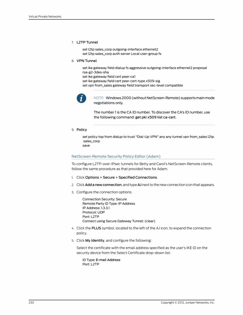
7. L2TP Tunnel
set l2tp sales_corp outgoing-interface ethernet2set l2tp sales_corp auth server Local user-group fs
8. VPN Tunnel
set ike gateway field dialup fs aggressive outgoing-interface ethernet2 proposalrsa-g2-3des-shaset ike gateway field cert peer-ca1set ike gateway field cert peer-cert-type x509-sigset vpn from_sales gateway field transport sec-level compatible
NOTE: Windows2000(withoutNetScreen-Remote)supportsmainmodenegotiations only.
The number 1 is the CA ID number. To discover the CA’s ID number, usethe following command: get pki x509 list ca-cert.
9. Policy
set policy top from dialup to trust “Dial-Up VPN” any any tunnel vpn from_sales l2tpsales_corpsave
NetScreen-Remote Security Policy Editor (Adam)
To configure L2TP-over-IPsec tunnels for Betty and Carol’s NetScreen-Remote clients,
follow the same procedure as that provided here for Adam.
1. Click Options > Secure > Specified Connections.
2. ClickAddanewconnection, and typeAJnext to the new connection icon that appears.
3. Configure the connection options:
Connection Security: SecureRemote Party ID Type: IP AddressIP Address: 1.3.3.1Protocol: UDPPort: L2TPConnect using Secure Gateway Tunnel: (clear)
4. Click the PLUS symbol, located to the left of the AJ icon, to expand the connection
policy.
5. Click My Identity, and configure the following:
Select the certificate with the email address specified as the user’s IKE ID on the
security device from the Select Certificate drop-down list:
ID Type: E-mail AddressPort: L2TP
Copyright © 2012, Juniper Networks, Inc.230
Virtual Private Networks

NOTE: The email address from the certificate appears in the identifierfield automatically.
6. Click the Security Policy icon, and select Aggressive Mode.
7. Click the PLUS symbol, located to the left of the Security Policy icon, and then the
PLUS symbol to the left of Authentication (Phase 1) and Key Exchange (Phase 2) to
expand the policy further.
8. Click Authentication (Phase 1) > Proposal 1: Select the following Authentication
Method and Algorithms:
Authentication Method: Pre-Shared Key(or)Authentication Method: RSA SignaturesHash Alg: SHA-1Key Group: Diffie-Hellman Group 2
9. Click Key Exchange (Phase 2) > Proposal 1: Select the following IPsec protocols:
Encapsulation Protocol (ESP): (select)Encrypt Alg: Triple DESHash Alg: SHA-1Encapsulation: Transport
10. Click Key Exchange (Phase 2) > Create NewProposal: Select the following IPsec
protocols:
Encapsulation Protocol (ESP): (select)Encrypt Alg: Triple DESHash Alg: MD5Encapsulation: Transport
11. Click Key Exchange (Phase 2) > Create NewProposal: Select the following IPsec
protocols:
Encapsulation Protocol (ESP): (select)Encrypt Alg: DESHash Alg: SHA-1Encapsulation: Transport
12. Click Key Exchange (Phase 2) > Create NewProposal: Select the following IPsec
protocols:
Encapsulation Protocol (ESP): (select)Encrypt Alg: DESHash Alg: MD5Encapsulation: Transport
13. Click File > Save Changes.
14. You also need to set up the network connection for your Windows 2000 operating
system using the Network Connection Wizard.
231Copyright © 2012, Juniper Networks, Inc.
Chapter 6: Layer 2 Tunneling Protocol
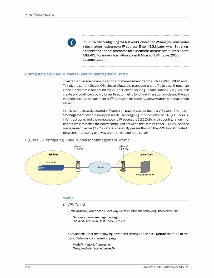
NOTE: Whenconfiguring theNetworkConnectionWizard, youmust entera destination hostname or IP address. Enter 1.3.3.1. Later, when initiatingaconnectionandareprompted forausernameandpassword, enteradam,AJbioJ15. For more information, consult MicrosoftWindows 2000documentation.
Configuring an IPsec Tunnel to Secure Management Traffic
To establish secure communications for management traffic such as Web, SNMP, and
Telnet, the current ScreenOS release allows the management traffic to pass through an
IPsec tunnel that is not bound to L2TP or Generic Routing Encapsulation (GRE). You can
create and configure a policy for an IPsec tunnel to function in transport mode and thereby
enable it to carry management traffic between the security gateway and the management
server.
In this example, as illustrated in Figure x on page y, you configure a VPN tunnel named
“management-vpn” in transport mode.The outgoing interface ethernet0/1(1.1.1.1/24) is
in Untrust zone, and the remote peer's IP address is 2.2.2.2/24. In this configuration, the
telnet traffic matches the policy configured between the Untrust zone(1.1.1.1/24) and the
management server (2.2.2.2) and successfully passes through the VPN tunnel created
between the security gateway and the management server.
Figure 63: Configuring IPsec Tunnel for Management Traffic
WebUI
1. VPN Tunnel
VPN>AutoKey Advanced>Gateway >New: Enter the following, then click OK:
Gateway name: management-gwIPv4/v6 Address/Host name : 2.2.2.2
>Advanced: Enter the following advanced settings, then click Return to return to the
basic Gateway configuration page:
Mode(Initiator): AggressiveOutgoing Interface: ethernet0/1
Copyright © 2012, Juniper Networks, Inc.232
Virtual Private Networks

Preshared Key: testSecurity Level: basic
VPN>AutoKey>New: Enter the following, then click OK:
VPN name: management–vpnRemote gateway: Predefined: (select)
>Advanced: Enter the following advanced settings, then click Return to return to the
basic AutoKey IKE configuration page:
Replay Protection: (clear)Security Level: basicTransport Mode: (select)
2. Policy
Policies >(From: Self, To:Untrust)> New: Enter the following, then click OK:
Source Address:Address book Entry: (select), Any-IPV4Destination Address:New Address: 2.2.2.2/32Service : TelnetAction : tunnelTunnel VPN : management-vpn
CLI
1. Policy
set policy from self to untrust “Any” “2.2.2.2/32” telent tunnel vpnmanagement-vpnsave
2. VPN
set ike gatewaymanagement-gw address 2.2.2.2 aggressive outgoing-interfaceethernet0/1 preshare test sec-level basic
set vpnmanagement-vpn gatewaymanagement-gw no-replay transport idletime 0
sec-level basicsave
NOTE: ScreenOS allowsmanagement traffic to pass-through only apolicy-based VPN established between the secured endpoints. Youmustspecify the following when you configure the policy for managementtraffic:
• Thesourcezoneshouldbeaself zoneandthesource IPaddress is “Any”.
• The destination zone should be aMGT zone and the destination IPaddress should be “Any”, if you configure the VPN in themanagementzone
233Copyright © 2012, Juniper Networks, Inc.
Chapter 6: Layer 2 Tunneling Protocol

Bidirectional L2TP-over-IPsec
In this example, ethernet1 (10.1.1.1/24) is the Trust zone interface and is in NAT mode,
and ethernet3 (1.1.1.1/24) is the Untrust zone interface. You create L2TP-over-IPsec
tunnels between a dialup user and a corporate LAN. The remote user is running an
X-Windows application, which requires bidirectional policies.
You configure incoming and outgoing policies for the dialup AutoKey IKE VPN tunnel
named VPN_dial for IKE user dialup-jwith IKE ID [email protected]., and the L2TP tunnel named
tun1. The IKE user initiates a IPsec connection to the security device from the Untrust
zone to reach corporate servers in the Trust zone. At this point, only L2TP communication
is allowed. After L2TP/PPP negotiation, the L2TP tunnel is established. With bidirectional
policies configured, traffic can initiate from either end of the tunnel.
The dialup user dialup-j uses a NetScreen-Remote client on a Windows 2000 operating
system. The NetScreen-Remote configuration for dialup user dialup-j is included after
Figure 64 on page 234.
Figure 64: Bidirectional L2TP-over-IPsec
LAN
Trust Zone
NetScreen-Remote ClientRunning X-Windows Server
ethernet31.1.1.1/24
External Router1.1.1.250
Internet
ethernet310.1.1.1/24
UNIX Server
Dialup Zone
L2TP-over-IPSecTunnel
NOTE: To configure an L2TP-over-IPsec tunnel forWindows 2000 (withoutNetScreen-Remote), the Phase 1 negotiationsmust be in mainmode andthe IKE ID typemust be ASN1-DN.
WebUI
1. Interfaces
Network > Interfaces > Edit (for ethernet1): Enter the following, then click Apply:
Zone Name: TrustStatic IP: (select this option when present)IP Address/Netmask: 10.1.1.1/24
Select the following, then click OK:
Interface Mode: NAT
Network > Interfaces > Edit (for ethernet3): Enter the following, then click OK:
Zone Name: UntrustStatic IP: (select this option when present)IP Address/Netmask: 1.1.1.1/24
Copyright © 2012, Juniper Networks, Inc.234
Virtual Private Networks

2. Address
Policy > Policy Elements > Addresses > List > New: Enter the following, then clickOK:
Address Name: trust_netIP Address/Domain Name:IP/Netmask: (select), 10.1.1.0/24
Zone: Trust
3. L2TP/IKE User
Objects > Users > Local > New: Enter the following, then click OK:
User Name: dialup-jStatus: EnableIKE User: (select)Simple Identity: (select)IKE Identity: [email protected]
Authentication User: (select)L2TP User: (select)User Password: abc123Confirm Password: abc123
NOTE: The IKE ID that you enter must be the same as the one that theNetScreen-Remote client sends, which is the email address that appearsin the certificate that the client uses for authentication.
4. L2TP
VPNs > L2TP > Tunnel > New: Enter the following, then click OK:
Name: tun1Use Default Settings: (select)Secret: netscreenKeepalive: 60
5. VPN
VPNs > AutoKey Advanced > Gateway > New: Enter the following, then click OK:
Gateway Name: dialup1Security Level: (select), StandardRemote Gateway Type: Dialup User; (select), dialup-jPreshared Key: n3TsCr33NOutgoing Interface: (select), ethernet3
> Advanced: Enter the following, and then click Return to return to the basic AutoKey
IKE Gateway configuration page:
Mode (Initiator): AggressiveEnable NAT-Traversal: (select)UDP Checksum: (select)Keepalive Frequency: 5
VPNs > AutoKey IKE > New: Enter the following, then click OK:
VPNName: VPN_dialRemote Gateway: Predefined: (select), dialup1
235Copyright © 2012, Juniper Networks, Inc.
Chapter 6: Layer 2 Tunneling Protocol

> Advanced: Enter the following, and then click Return to return to the basic AutoKey
IKE configuration page:
Security Level: Standard (select)Transport Mode (For L2TP-over-IPsec only): (select)
6. Route
Network > Routing > Routing Entries > New: Enter the following, then click OK:
Network Address/Netmask: 0.0.0.0/0Gateway: (select)Interface: ethernet3Gateway IP Address: 1.1.1.250
7. Policies
Policies > (From: Untrust, To: Trust) > New: Enter the following, then click OK:
Source Address:Address Book Entry: (select), Dial-Up VPN
Destination Address:Address Book Entry: (select), trust_net
Service: ANYAction: TunnelTunnel VPN: VPN_dialModify matching bidirectional VPN policy: (select)
L2tp: (select) tun1
Policies > (From: Trust, To: Untrust) > New: Enter the following, then click OK:
Source Address:Address Book Entry: (select), trust_net
Destination Address:Address Book Entry: (select), Dial-Up VPN
Service: ANYAction: TunnelTunnel VPN: VPN_dialModify matching bidirectional VPN policy: (select)
L2TP: tun1
CLI
1. Interfaces
set interface ethernet1 zone trustset interface ethernet1 ip 10.1.1.1/24set interface ethernet1 natset interface ethernet3 zone untrustset interface ethernet3 ip 1.1.1.1/24
2. Address
set address trust trust_net 10.1.1.0/24
3. L2TP/IKE User
set user dialup-j ike-id u-fqdn [email protected] user dialup-j type auth ike l2tpset user dialup-j password abc123
Copyright © 2012, Juniper Networks, Inc.236
Virtual Private Networks

4. L2TP
set L2TP tun1 outgoing-interface ethernet3 secret "netscreen" keepalive 60
5. VPN
set ike gateway dialup1 dialup "dialup-j" aggressive outgoing-interface ethernet3preshare n3TsCr33N sec-level standardset ike gateway dialup1 nat-traversal udp-checksumset ike gateway dialup1 nat-traversal keepalive-frequency 5set vpn VPN_dial gateway dialup1 no-replay transport idletime 0 sec-level standard
6. Route
set vrouter trust-vr route 0.0.0.0/0 interface ethernet3 gateway 1.1.1.250
7. Policies
set policy from untrust to trust “Dial-Up VPN” “trust_net” any tunnel vpn VPN_dialtun1set policy from trust to untrust trust_net “Dial-Up VPN” any tunnel vpn VPN_dial l2tptun1save
NetScreen-Remote Security Policy Editor (for User “dialup-j”)
1. Click Options > Secure > Specified Connections.
2. Click Add a new connection, and type dialup-j next to the new connection icon that
appears.
3. Configure the connection options:
Connection Security: SecureRemote Party ID Type: IP AddressIP Address: 1.1.1.1Protocol: UDPPort: L2TPConnect using Secure Gateway Tunnel: (clear)
4. Click thePLUS symbol, located to the left of the dialup-j icon, to expand the connection
policy.
5. Click My Identity, and configure the following:
Select the certificate with the email address specified as the user’s IKE ID on the
security device from the Select Certificate drop-down list
ID Type: E-mail AddressPort: L2TP
NOTE: The email address from the certificate appears in the identifierfield automatically.
6. Click the Security Policy icon, and select Aggressive Mode.
237Copyright © 2012, Juniper Networks, Inc.
Chapter 6: Layer 2 Tunneling Protocol

7. Click the PLUS symbol, located to the left of the Security Policy icon, and then the
PLUS symbol to the left of Authentication (Phase 1) and Key Exchange (Phase 2) to
expand the policy further.
8. Click Authentication (Phase 1) > Proposal 1: Select the following Authentication
method and algorithms:
Authentication Method: Pre-Shared Key(or)Authentication Method: RSA SignaturesHash Alg: SHA-1Key Group: Diffie-Hellman Group 2
NOTE: WhenPerfectForwardingSecrecy (PFS) isenabledon thesecuritydevice (DF group 1,2, or 5), it must also be enabled for the VPN client inNetScreen-Remote.
9. Click Key Exchange (Phase 2) > Proposal 1: Select the following IPsec protocols:
Encapsulation Protocol (ESP): (select)Encrypt Alg: Triple DESHash Alg: SHA-1Encapsulation: Transport
10. Click Key Exchange (Phase 2) > Create NewProposal: Select the following IPsec
protocols:
Encapsulation Protocol (ESP): (select)Encrypt Alg: Triple DESHash Alg: MD5Encapsulation: Transport
11. Click Key Exchange (Phase 2) > Create NewProposal: Select the following IPsec
protocols:
Encapsulation Protocol (ESP): (select)Encrypt Alg: DESHash Alg: SHA-1Encapsulation: Transport
12. Click Key Exchange (Phase 2) > Create NewProposal: Select the following IPsec
protocols:
Encapsulation Protocol (ESP): (select)Encrypt Alg: DESHash Alg: MD5Encapsulation: Transport
13. Click File > Save Changes.
You also need to set up the network connection for your Windows 2000 operating system
using the Network Connection Wizard.
Copyright © 2012, Juniper Networks, Inc.238
Virtual Private Networks

NOTE: When you configure the Network ConnectionWizard, youmust entera destination hostname or IP address. Enter 1.1.1.1. Later, when you initiate aconnection and are prompted for a username and password, enter dialup-j,abc123. For more information, consult your MicrosoftWindows 2000documentation.
239Copyright © 2012, Juniper Networks, Inc.
Chapter 6: Layer 2 Tunneling Protocol

Copyright © 2012, Juniper Networks, Inc.240
Virtual Private Networks

CHAPTER 7
Advanced Virtual Private NetworkFeatures
This chapter covers the following uses of virtual private network (VPN) technology:
• NAT-Traversal on page 241
• VPN Monitoring on page 251
• Multiple Tunnels per Tunnel Interface on page 263
• Multiple Proxy IDs on a Route-Based VPN on page 298
• Redundant VPN Gateways on page 302
• Creating Back-to-Back VPNs on page 313
• Creating Hub-and-Spoke VPNs on page 320
• IKE and IPsec Passthrough Traffic on page 328
NAT-Traversal
Network Address Translation (NAT) and Network Address Port Translation (NAPT) are
Internet standards that allow a local-area network (LAN) to use one set of IP addresses
for internal traffic and a second set of addresses for external traffic. NAT devices generate
these external addresses from predetermined pools of IP addresses.
When setting up an IPsec tunnel, the presence of a NAT device along the data path has
no effect on Phase 1 and Phase 2 IKE negotiations, which always encapsulate IKE packets
within User Datagram Protocol (UDP) segments. However, after the Phase 2 negotiations
complete, performing NAT on the IPsec packets causes the tunnel to fail. Of the many
reasons why NAT causes disruption to IPsec, one reason is that, for the Encapsulating
Security Protocol (ESP), NAT devices cannot discern the location of the Layer 4 header
for port translation (because it is encrypted). For the Authentication Header (AH) protocol,
NAT devices can modify the port number, but the authentication check, which includes
the entire IPsec packet, fails.
NOTE: For a list of IPsec/NAT incompatibilities, refer todraft-ietf-ipsec-nat-regts-00.txt by Bernard Aboba.
241Copyright © 2012, Juniper Networks, Inc.

To solve these problems, security devices and the NetScreen-Remote client (version 6.0
or later) can apply a NAT-Traversal (NAT-T) feature. NAT-T adds a layer of UDP
encapsulation to IPsec packets after detecting one or more NAT devices along the data
path during Phase 1 exchanges, as prescribed in the IETF drafts
draft-ietf-ipsec-nat-t-ike-00.txt and draft-ietf-ipsec-udp-encaps-00.txt, as well as in
later versions of these drafts.
NOTE: NetScreen-Remote 6 and NetScreen-Remote 7 support NAT-T asdescribed in draft-ietf-ipsec-nat-t-ike-00.txt anddraft-ietf-ipsec-udp-encaps-00.txt. NetScreen-Remote 8.2 supports draft02.
NAT devices can create another problem if they are also IKE/IPsec-aware and attempt
to process packets with the IKE port number of 500 or the IPsec protocol numbers 50
(for ESP) and 51 (for AH). To avoid such intermediary processing of IKE packets, version
2 of the previously mentioned IETF drafts proposes the shifting (or “floating”) of UDP
port numbers for IKE from 500 to 4500. To avoid intermediary processing of IPsec
packets, both drafts 0 and 2 insert a UDP header between the outer IP header and the
ESP or AH header, thereby changing the value in the Protocol field from 50 or 51 (for ESP
or AH, respectively) to 17 (for UDP). In addition, the inserted UDP header also uses port
4500. The current version of ScreenOS supports NAT-T based on
draft-ietf-ipsec-nat-t-ike-02.txtanddraft-ietf-ipsec-udp-encaps-02.txt, as well as version
0 of these drafts.
NOTE: ScreenOS does not support NAT-T for Manual Key tunnels nor forIPsec trafficusingAH.ScreenOSonlysupportsNAT-T forAutoKey IKE tunnelsusing ESP.
Probing for NAT
To check that both ends of the VPN tunnel support NAT-T, ScreenOS sends two MD-5
hashes in the vendor ID payload in the first two exchanges of Phase 1 negotiations—one
hash for the title of draft 0 and one of the title for draft 2:
• “4485152d 18b6bbcd 0be8a846 9579ddcc” —which is an MD-5 hash of
“draft-ietf-ipsec-nat-t-ike-00”
• “90cb8091 3ebb696e 086381b5 ec427b1f” —which is an MD-5 hash of
“draft-ietf-ipsec-nat-t-ike-02”
Both peers must send and receive at least one of these values in the vendor payload ID
for the NAT-T probe to continue. If they send hashes for both drafts, ScreenOS uses the
NAT-T implementation for draft 2.
If the devices at each endpoint support NAT-T, they send each other NAT discovery
(NAT-D) payloads in the third and fourth Phase 1 exchanges (main mode) or in the second
and third exchanges (aggressive mode). The NAT discovery (NAT-D) payload is a IKE
Copyright © 2012, Juniper Networks, Inc.242
Virtual Private Networks

payload type for NAT-T. The NAT-D payload type number is 0130. For a list of other IKE
payload types, see “IKE Packets” on page 15.
NOTE: ScreenOS can handlemultiple NAT-Discovery (NAT-D) payloads inan IKE negotiation.
The NAT-D payloads contain a negotiated hash of the following information:
• Destination NAT-D hash:
• Initiator’s cookie (CKY-I)
• Responder’s cookie (CKY-R)
• Remote (destination) IKE peer’s IP address
• Destination port number
• Source NAT-D hash (one or more):
• Initiator’s cookie (CKY-I)
• Responder’s cookie (CKY-R)
• Local (source) IKE peer’s IP address
• Source port number
NOTE: NAT-T supports multiple source NAT-D hashes for devices withmultiple interfacesand implementations thatdonot specifyanoutgoinginterface.
When each peer compares the hashes it receives with the ones it sends, it can tell if
address translation has occurred between them. Distinguishing which packet has been
modified also indicates the location of the NAT device:
ThenMatchesIf
no address translation hasoccurred.
at least one of the remotepeer’s source hashes
the local peer’s destinationhash
no address translation hasoccurred.
the remote peer’s destinationhash
at least one of the local peer’ssource hashes
ThenDoes not matchIf
no address translation hasoccurred.
at least one of the remotepeer’s source hashes
the local peer’s destinationhash
243Copyright © 2012, Juniper Networks, Inc.
Chapter 7: Advanced Virtual Private Network Features

ThenDoes not matchIf
no address translation hasoccurred.
the remote peer’s destinationhash
at least one of the local peer’ssource hashes
Knowing the location of the NAT device is important because IKE keepalives must initiate
from the peer behind the NAT device. See “Keepalive Packets” on page 246.
If both peers support IETF draft 2, then they also float the IKE port number from 500 to
4500 as soon as they detect a NAT device between themselves during Phase 1
negotiations. In main mode, the port numbers float to 4500 in the fifth and sixth
exchanges of Phase 1, and then for all Phase 2 exchanges. In aggressive mode, the port
number floats to 4500 in the third—and final—exchange of Phase 1, and then for all Phase
2 exchanges. The peers also use 4500 for the UDP port number for all subsequent IPsec
traffic.
Traversing a NAT Device
In Figure 65 on page 244, a NAT device at the perimeter of a hotel LAN receives a packet
from a VPN dialup client with IP address 2.1.1.5, assigned by the hotel. For all outbound
traffic, the NAT device replaces the original source IP address in the outer header with a
new address 2.2.2.2. During Phase 1 negotiations, the VPN client and the security device
detect that both VPN participants support NAT-T, that a NAT device is present along
the data path, and that it is located in front of the VPN client.
Figure 65: NAT-Traversal
Corporate
Security Device
Hotel
NAT Device
VPN Tunnel
Internet
VPN Dialup Client
Src IP 200.1.1.1 210.2.2.2
Encapsulating the IPsec packets within UDP packets—which both the VPN client and
the security device do—solves the problem of the authentication check failure. The NAT
device processes them as UDP packets, changing the source port in the UDP header and
leaving the SPI in the AH or ESP header unmodified. The VPN participants strip off the
UDP layer and process the IPsec packets, which pass the authentication check because
none of the authenticated content has been changed.
Another problem can arise if the NAT device is IKE/IPsec-aware. An IKE/IPsec-aware
NAT device might attempt to process IKE/IPsec traffic instead of forwarding it. To prevent
such intermediary processing, NAT-T (v2) changes the source and destination UDP port
numbers for IKE from 500 to 4500. NAT-T also inserts a non-ESP marker in the UDP
header just before the payload. For IPsec traffic, NAT-T (v0 and v2) inserts a UDP header
between the outer IP header and the ESP header. The UDP packet also uses 4500 for
both the source and destination port numbers.
Copyright © 2012, Juniper Networks, Inc.244
Virtual Private Networks

As mentioned, NAT-T (v2) adds a non-ESP marker between the header and payload of
the UDP segment encapsulating the ISAKMP packet. The non-ESP marker is 4 bytes of
zero (0000), and is added to the UDP segment to distinguish an encapsulated ISAKMP
packet from an encapsulated ESP packet, which does not have such a marker. Without
the non-ESP marker, the recipient would be unsure if the encapsulated packet was an
ISAKMP packet or an ESP packet because the UDP header uses 4500 for both types.
Using this marker indicates the correct type of packet that is encapsulated so that the
recipient can correctly demultiplex it.
As shown in Figure 66 on page 245, after detecting a NAT device in the data path, the
source and destination port numbers in the UDP header of an IKE packet change from
500 to 4500. Also, the VPN tunnel endpoints insert a non-ESP marker between the UDP
header and payload to distinguish the encapsulated ISAKMP packet from an ESP packet.
The recipient can use this marker to distinguish the encapsulated ISAKMP packet from
an ESP packet and demultiplex it correctly.
Figure 66: IKE Packet (for Phases 1 and 2)
Figure 67 on page 246 shows how, after detecting a NAT device in the data path, the VPN
tunnel endpoints insert an additional UDP header between the outer IP header and the
ESP header of an IPsec packet. Because there is no non-ESP marker, the recipient can
distinguish the encapsulated ESP packet from an ISAKMP packet and demultiplex the
ESP packet correctly.
245Copyright © 2012, Juniper Networks, Inc.
Chapter 7: Advanced Virtual Private Network Features

Figure 67: IPsec ESP Packet Before and After NAT Detection
UDP Checksum
All UDP packets contain a UDP checksum, a calculated value that ensures UDP packets
are free of transmission errors. A security device does not require use of the UDP checksum
for NAT-T, so the WebUI and CLI present the checksum as an optional setting. Even so,
some NAT devices require a checksum, so you might have to enable or disable this setting.
By default, the UDP checksum is included when you enable NAT-T.
WebUI
VPNs > AutoKey Advanced > Gateway > New:
Enter the necessary parameters for the new tunnel gateway as described in “Site-to-Site
Virtual Private Networks” on page 91 or “Dialup Virtual Private Networks” on page 169;
enter the following, then click OK:
> Advanced: Enter the following advanced settings, then click Return to return to the
basic Gateway configuration page:
Enable NAT-Traversal: (select)UDP Checksum: Enable
CLI
set ike gateway name nat-traversal udp-checksumunset ike gateway name nat-traversal udp-checksum
Keepalive Packets
When a NAT device assigns an IP address to a host, the NAT device determines how long
the new address remains valid when no traffic occurs. For example, a NAT device might
Copyright © 2012, Juniper Networks, Inc.246
Virtual Private Networks

invalidate any generated IP address that remains unused for 20 seconds. Therefore, it is
usually necessary for the IPsec participants to send periodic keepalive packets—empty
UDP packets—through the NAT device, so that the NAT mapping does not change until
the Phase 1 and Phase 2 SAs expire.
NOTE: NAT devices have different session timeout intervals, depending onthemanufacturer andmodel. It is important to determine what the intervalis for the NAT device and to set the keepalive frequency value below that.
Initiator/Responder Symmetry
When two security devices establish a tunnel in the absence of a NAT device, either
device can serve as initiator or responder. However, if either host resides behind a NAT
device, such initiator/responder symmetry might be impossible. This happens whenever
the NAT device generates IP addresses dynamically.
Figure 68: Security Device with a Dynamically Assigned IP Address Behind a NAT Device
In Figure 68 on page 247, Device B resides in a subnet located behind a NAT device. If the
NAT device generates new source IP addresses for packets it receives from
Device B—drawing them dynamically from a pool of IP addresses—Device A cannot
unambiguously identify Device B. Therefore, Device A cannot successfully initiate a tunnel
with Device B. Device A must be the responder, Device B the initiator, and they must
perform Phase 1 negotiations in aggressive mode.
However, if the NAT device generates the new IP address using a mapped IP (MIP)
address, or some other one-to-one addressing method, Device A can unambiguously
identify Device B. Consequently, either Device A or Device B can be the initiator, and both
can use main or aggressive mode for Phase 1. Device B, which is not behind the NAT
device, configures this new IP address as the IKE gateway address. At this time, the local
ID or ID (peer ID) needs to be set.
247Copyright © 2012, Juniper Networks, Inc.
Chapter 7: Advanced Virtual Private Network Features

NOTE: If you enable NAT-T on a security device acting as the responder andconfigure it to perform IKE negotiations inmainmode, that device and all itspeers of the following types that are configured on the same outgoinginterfacemust use the same Phase 1 proposals presented in the same orderas each other:
Dynamic peer (peers with dynamically assigned IP addresses)Dialup VPN usersPeers with static IP addresses behind a NAT device
Because it is not possible to know the identity of a peer when negotiatingPhase 1 in mainmode until the last twomessages, the Phase 1 proposalsmust all be the same so that IKE negotiations can proceed.
The security device automatically checks that all Phase 1 proposals are thesame and in the same order when you configure IKE in mainmode to one ofthe above peer types on the same outgoing interface. If the proposals aredifferent, the security device generates an error message.
In the example shown in Figure 69 on page 248, two devices, Device A and Device B, are
connected by a VPN tunnel. Device A is behind a NAT and has a private IP 31.0.0.14. The
NAT generates a new public IP using MIP for Device A. You use the MIP address as the
gateway address while configuring IKEv2 gateway on Device B. For more information
about MIPs, see Mapped IP Addresses.
Figure69:SecurityDevicewithaMapped IPAddressBehindaNATDevice
Device A Configuration
set ike gateway ikev2 "dev-b" address 33.0.0.15 id "dev-b.net" local-id "dev-a.net"outgoing-interface"ethernet0/1"preshare"KghBa3TbNruG2Es6e2C5zkr83SnLzIy1MQ=="proposal "pre-g2-3des-md5"set ike gateway ikev2 "dev-b" nat-traversalset ike gateway ikev2 "dev-b" nat-traversal udp-checksumset ike gateway ikev2 "dev-b" nat-traversal keepalive-frequency 5setvpn"dev-b"gateway"dev-b"no-replaytunnel idletime0proposal"g2-esp-3des-md5"set vpn "dev-b" id 0x1 bind interface tunnel.1
Device B Configuration
set ike gateway ikev2 "dev-a" address 33.0.0.14 id "dev-a.net" local-id "dev-b.net"outgoing-interface "ethernet2/3" preshare"5LXhnzFYNz8EO6srN9CgzDdrpKnEep28Uw==" proposal "pre-g2-3des-md5"set ike gateway ikev2 "dev-a" nat-traversalset ike gateway ikev2 "dev-a" nat-traversal udp-checksumset ike gateway ikev2 "dev-a" nat-traversal keepalive-frequency 5
Copyright © 2012, Juniper Networks, Inc.248
Virtual Private Networks

setvpn"dev-a"gateway"dev-a"no-replaytunnel idletime0proposal"g2-esp-3des-md5"set vpn "dev-a" id 0x1 bind interface tunnel.1
Enabling NAT-Traversal
In Figure 70 on page 249, a NAT device at the perimeter of a hotel LAN assigns an address
to the VPN dialup client used by Jozef, a salesman attending a convention. For Jozef to
reach the corporate LAN through a dialup VPN tunnel, you must enable NAT-T for the
remote gateway “jozef,” configured on the security device, and for the remote gateway
configured on the VPN dialup client. You also enable the security device to include a UDP
checksum in its transmissions, and you set the keepalive frequency to 8 seconds.
Figure 70: Enabling NAT-Traversal
Corporate
Security Device
Hotel
NAT Device
VPN Tunnel
Internet
VPN Dialup Client
WebUI
VPNs > AutoKey Advanced > Gateway > New: Enter the necessary parameters for the
new tunnel gateway (described in “Site-to-Site Virtual Private Networks” on page 91 or
“Dialup Virtual Private Networks” on page 169), enter the following, then click OK:
> Advanced: Enter the following advanced settings, then click Return to return to the
basic Gateway configuration page:
Enable NAT-Traversal: (select)UDP Checksum: EnableKeepalive Frequency: 8 Seconds (0~300 Sec)
NOTE: When you configure a dialupVPN through theCLI, the security deviceautomatically enables NAT-Traversal.
CLI
set ike gateway jozef nat-traversalset ike gateway jozef nat-traversal udp-checksumset ike gateway jozef nat-traversal keepalive-frequency 8save
Using IKE IDs with NAT-Traversal
When two VPN gateways negotiate in main mode, they exchange IP addresses in order
to identify each other and activate the tunnel. When devices at either or both ends of the
tunnel have dynamically assigned IP addresses, however, you must configure IKE IDs
(local ID and peer ID) on the devices at both ends of the tunnel. An IKE ID is a unique
249Copyright © 2012, Juniper Networks, Inc.
Chapter 7: Advanced Virtual Private Network Features

identifier that remains static. The IKE ID is set up during the phase when you configure
the IKE gateway.You configure IKE IDs instead of remote IP address.
Without NAT-T, a VPN tunnel can be activated using only the local ID on the local side
and only the peer ID on the remote side. But when using NAT-Traversal with dynamic
VPN in main mode using certificates, you must set both the local ID and peer ID on both
sides of the VPN tunnel. The following example shows how you can configure local IDs
and peer IDs on firewall1 and firewall2 so they can identify each other and activate a
tunnel between them.
WebUI
On firewall1, enter the following:
VPNs > AutoKey IKE Advanced> Gateway > New: Enter the following, then clickAdvanced:
Gateway Name: test_gwAddress/Hostname: 0.0.0.0Peer-ID: firewall2
Click Advanced, then enter the following:
Security Level: StandardLocal-ID: firewall1Outgoing Interface: ethernet0/0Mode: MainSecurity Level: Standard
On firewall2, enter the following:
VPNs > AutoKey IKE Advanced> Gateway > New: Enter the following, then clickAdvanced:
Gateway Name: gw_bap15_p1Address/Hostname: 1.1.1.1Peer-ID: firewall1
Click Advanced, then enter the following:
Security Level: StandardLocal-ID: firewall2Outgoing Interface: ethernet0/0Mode: MainSecurity Level: Standard
CLI
On firewall1, enter the following:
set ike gateway test-gw address 0.0.0.0 id firewall2 main local-id firewall1outgoing-interface ethernet0/0 proposal standard
On firewall2, enter the following
set ike gateway gw_bap15_p1 address 1.1.1.1 id firewall1 main local-id firewall2outgoing-interface ethernet0/0 proposal standard
Copyright © 2012, Juniper Networks, Inc.250
Virtual Private Networks

The following table shows the CLI command for each of the IPsec NAT-T tasks:
Use This CLI CommandTo
set ike nat-t gateway nameEnable IPsec NAT-T per gateway
unset ike nat-t gateway nameDisable IPsec NAT-T per gateway
set ike nat-t keep-alive period secondsSet the IPsec NAT-T keepalive per gateway
set ike nat-t keep-alive count countSet the IPsec NAT-T keepalive count per gateway
get ike nat-t gateway nameGet the IPsec NAT-T status
VPNMonitoring
When you enable VPN monitoring for a specific tunnel, the security device sends ICMP
echo requests (or “pings”) through the tunnel at specified intervals (configured in seconds)
to monitor network connectivity through the tunnel.
NOTE: To change the ping interval, you can use the following CLI command:set vpnmonitor interval number. The default is 10 seconds.
If the ping activity indicates that the VPN monitoring status has changed, the security
device triggers one of the following Simple Network Management Protocol (SNMP)
traps:
• Up to Down: This trap occurs when the state of VPN monitoring for the tunnel is up,
but a specified consecutive number of ICMP echo requests does not elicit a reply and
there is no other incoming VPN traffic. Then the state changes to down.
• Down to Up: When the state of VPN monitoring for the tunnel is down, but the ICMP
echo request elicits a single response, then the state changes to up. The down-to-up
trap occurs only if you have disabled the rekey option and the Phase 2 SA is still active
when an ICMP echo request elicits a reply through the tunnel.
NOTE: Tochangethethreshold for thenumberofconsecutiveunsuccessfulICMP echo requests, you can use the following CLI command: setvpnmonitor threshold number. The default is 10 consecutive requests.
Formore information about theSNMPdata thatVPNmonitoring provides,see “SNMP VPNMonitoring Objects and Traps” on page 262.
You apply VPN monitoring per VPN object, not necessarily per VPN tunnel. A VPN object
is what you define with the set vpn command or with its WebUI counterpart. After you
define one VPN object, you can then reference it in one or more policies (creating
policy-based VPNs). Because ScreenOS derives a policy-based VPN tunnel from a VPN
251Copyright © 2012, Juniper Networks, Inc.
Chapter 7: Advanced Virtual Private Network Features
object plus the other policy parameters, a single VPN object can be an element in
numerous VPN tunnels. This distinction between VPN object and VPN tunnel is important
because Juniper Networks recommends that you apply VPN monitoring to no more than
100 IPsec VPN tunnels—if you do not enable optimization. If you do enable optimization,
then there is no limitation to the number of VPN tunnels to which you can apply VPN
monitoring. To learn about the optimization option, see “Rekey and Optimization Options”
on page 252.
NOTE: VPNmonitoring optimization operates on aper-object basis. You canenable it on all VPN objects, on none, or only on some.
Rekey and Optimization Options
If you enable the rekey option, the security device starts sending ICMP echo requests
immediately upon completion of the tunnel configuration and continues to send them
indefinitely. The echo requests trigger an attempt to initiate IKE negotiations to establish
a VPN tunnel until the state of VPN monitoring for the tunnel is up. The security device
then uses the pings for VPN monitoring purposes. If the state of VPN monitoring for the
tunnel changes from up to down, the security device deactivates its Phase 2 security
association (SA) for that peer. The security device continues to send echo requests to
its peer at defined intervals, triggering attempts to reinitiate IKE Phase 2 negotiations—and
Phase 1 negotiations, if necessary—until it succeeds. At that point, the security device
reactivates the Phase 2 SA, generates a new key, and reestablishes the tunnel. A message
appears in the event log stating that a successful rekey operation has occurred.
NOTE: If a security device is a DHCP client, a DHCP update to a differentaddress causes IKE to rekey. However, a DHCP update to the same addressdoes not provoke the IKE rekey operation.
You can use the rekey option to ensure that an AutoKey IKE tunnel is always up, perhaps
to monitor devices at the remote site or to allow dynamic routing protocols to learn routes
at a remote site and transmit messages through the tunnel. Another use to which you
can apply VPN monitoring with the rekey option is for automatic population of the
next-hop tunnel binding table (NHTB table) and the route table when multiple VPN
tunnels are bound to a single tunnel interface. For an example of this last use, see “Multiple
Tunnels per Tunnel Interface” on page 263.
If you disable the rekey option, the security device performs VPN monitoring only when
the tunnel is active with user-generated traffic.
By default, VPN monitoring optimization is disabled. If you enable it (set vpn name
monitor optimized), the VPN monitoring behavior changes as follows:
• The security device considers incoming traffic through the VPN tunnel to be the
equivalent of ICMP echo replies. Accepting incoming traffic as a substitute for ICMP
echo replies can reduce false alarms that might occur when traffic through the tunnel
is heavy and the echo replies do not get through.
Copyright © 2012, Juniper Networks, Inc.252
Virtual Private Networks
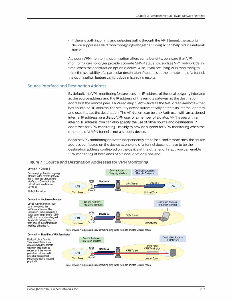
• If there is both incoming and outgoing traffic through the VPN tunnel, the security
device suppresses VPN monitoring pings altogether. Doing so can help reduce network
traffic.
Although VPN monitoring optimization offers some benefits, be aware that VPN
monitoring can no longer provide accurate SNMP statistics, such as VPN network delay
time, when the optimization option is active. Also, if you are using VPN monitoring to
track the availability of a particular destination IP address at the remote end of a tunnel,
the optimization feature can produce misleading results.
Source Interface and Destination Address
By default, the VPN monitoring feature uses the IP address of the local outgoing interface
as the source address and the IP address of the remote gateway as the destination
address. If the remote peer is a VPN dialup client—such as the NetScreen-Remote—that
has an internal IP address, the security device automatically detects its internal address
and uses that as the destination. The VPN client can be an XAuth user with an assigned
internal IP address, or a dialup VPN user or a member of a dialup VPN group with an
internal IP address. You can also specify the use of other source and destination IP
addresses for VPN monitoring—mainly to provide support for VPN monitoring when the
other end of a VPN tunnel is not a security device.
Because VPN monitoring operates independently at the local and remote sites, the source
address configured on the device at one end of a tunnel does not have to be the
destination address configured on the device at the other end. In fact, you can enable
VPN monitoring at both ends of a tunnel or at only one end.
Figure 71: Source and Destination Addresses for VPNMonitoring
253Copyright © 2012, Juniper Networks, Inc.
Chapter 7: Advanced Virtual Private Network Features

NOTE: If the other end of a tunnel is the NetScreen-Remote VPN client thatreceives its address throughXAuth, then the security device, by default, usesthe XAuth-assigned IP address as the destination for VPNmonitoring. Forinformation about XAuth, see XAuth Users and User Groups.
Policy Considerations
You must create a policy on the sending device to permit pings from the zone containing
the source interface to pass through the VPN tunnel to the zone containing the destination
address if:
• The source interface is in a different zone from the destination address
• The source interface is in the same zone as the destination address, and intrazone
blocking is enabled
Likewise, you must create a policy on the receiving device to permit pings from the zone
containing the source address to pass through the VPN tunnel to the zone containing
the destination address if:
• The destination address is in a different zone from the source address
• The destination address is in the same zone as the source address, and intrazone
blocking is enabled
NOTE: If the receivingdevice isa third-partyproduct thatdoesnot respondto the ICMP echo requests, change the destination to an internal host inthe remote peer’s LAN that does respond. The remote peer’s firewallmusthave a policy permitting the ICMP echo requests to pass through it.
Configuring the VPNMonitoring Feature
To enable VPN monitoring, do the following:
WebUI
VPNs > AutoKey IKE > New: Configure the VPN, clickAdvanced, enter the following, click
Return to go back to the basic VPN configuration page, then click OK:
VPN Monitor: Select to enable VPN monitoring of this VPN tunnel.
Source Interface: Choose an interface from the drop-down list. If you choose default,the security device uses the outgoing interface.
Destination IP: Enter a destination IP address. If you do not enter anything, the security
device uses the remote gateway IP address.
Rekey: Select this option if you want the security device to attempt IKE Phase 2
negotiations—and IKE Phase 1 negotiations if necessary—if the tunnel status changes
from up to down. When you select this option, the security device attempts IKE
Copyright © 2012, Juniper Networks, Inc.254
Virtual Private Networks

negotiations to set up the tunnel and begin VPN monitoring immediately after you finish
configuring the tunnel.
Clear this option if you do not want the security device to attempt IKE negotiations if the
tunnel status changes from up to down. When the rekey option is disabled, VPN monitoring
begins after user-generated traffic has triggered IKE negotiations and stops when the
tunnel status changes from up to down.
(Or)
VPNs > Manual Key > New: Configure the VPN, clickAdvanced, enter the following, click
Return to go back to the basic VPN configuration page, then click OK:
VPN Monitor: Select to enable VPN monitoring of this VPN tunnel.
Source Interface: Choose an interface from the drop-down list. If you choose default,the security device uses the outgoing interface.
Destination IP: Enter a destination IP address. If you do not enter anything, the security
device uses the remote gateway IP address.
CLI
set vpnmonitor frequency numberset vpnmonitor threshold numbersetvpnname_strmonitor [source-interface interface [destination-ip ip_addr ] [optimized][ rekey ]save
NOTE: The VPNmonitoring frequency is in seconds. The default setting is10-second intervals.
The VPNmonitoring threshold number is the consecutive number ofsuccessful or unsuccessful ICMPecho requests that determineswhether theremote gateway is reachable through the VPN tunnel or not. The defaultthreshold is 10 consecutive successful or 10 consecutive unsuccessful ICMPecho requests.
If you do not choose a source interface, the security device uses the outgoinginterface as the default.
If you do not choose a destination IP address, the security device uses the IPaddress for the remote gateway.
The rekey option is not available for Manual Key VPN tunnels.
In this example, you configure an AutoKey IKE VPN tunnel between two security devices
(Device A and Device B). On Device A, you set up VPN monitoring from its Trust zone
interface (ethernet1) to the Trust zone interface (10.2.1.1/24) on Device B. On the Device B,
you set up VPN monitoring from its Trust zone interface (ethernet1) to a corporate intranet
server (10.1.1.5) behind Device A.
255Copyright © 2012, Juniper Networks, Inc.
Chapter 7: Advanced Virtual Private Network Features

NOTE: A Phase 1 security level of Compatible includes these proposals:pre-g2-3des-sha, pre-g2-3des-md5, pre-g2-des-sha, and pre-g2-des-md5.
A Phase 2 security level of Compatible includes these proposals:nopfs-esp-3des-sha, nopfs-esp-3des-md5, nopfs-esp-des-sha, andnopfs-esp-des-md5.
Device BDevice A
Zones and Interfaces
• ethernet1
• Zone: Trust
• IP address: 10.2.1.1/24
• Interface mode: NAT
• ethernet3
• Zone: Untrust
• IP address: 2.2.2.2/24
• ethernet1
• Zone: Trust
• IP address: 10.1.1.1/24
• Interface mode: NAT
• ethernet3
• Zone: Untrust
• IP address: 1.1.1.1/24
Route-Based AutoKey IKE Tunnel Parameters
• Phase 1
• Gateway name: gw1
• Gateway static IP address: 1.1.1.1
• Proposals: Compatible
• Preshared Key: Ti82g4aX
• Outgoing interface: ethernet3
• Mode: Main
• Phase 2
• VPN tunnel name: vpn1
• Security level: Compatible
• VPN Monitoring: src = ethernet1; dst =10.1.1.5
• Bound to interface: tunnel.1
• Phase 1
• Gateway name: gw1
• Gateway static IP address: 2.2.2.2
• Security level: Compatible
• Preshared Key: Ti82g4aX
• Outgoing interface: ethernet3
• Mode: Main
• Phase 2
• VPN tunnel name: vpn1
• Security level: Compatible
• VPN Monitoring: src = ethernet1; dst =10.2.1.1
• Bound to interface: tunnel.1
Device BDevice A
Routes
To 0.0.0.0/0, use ethernet3, gateway 2.2.2.250
To 10.1.1.0/24, use tunnel.1, no gateway
(Null route–to drop traffic to 10.1.1.0/24 if tunnel.1goes down) To 10.1.1.0/24, use null interface,metric: 10
To 0.0.0.0/0, use ethernet3, gateway 1.1.1.250
To 10.2.1.0/24, use tunnel.1, no gateway
(Null route–to drop traffic to 10.2.1.0/24 iftunnel.1 goes down) To 10.2.1.0/24, use nullinterface, metric: 10
Copyright © 2012, Juniper Networks, Inc.256
Virtual Private Networks

Because both devices ping from an interface in their Trust zone to an address in their
Untrust zone, the admins at both ends of the VPN tunnel must define policies permitting
pings to pass from zone to zone.
NOTE: Because both VPN terminators are security devices in this example,youcanuse thedefault sourceanddestinationaddresses forVPNmonitoring.Theuseofother options is includedpurely to illustratehowyoucanconfigurea security device to use them.
WebUI (Device A)
1. Interfaces
Network > Interfaces > Edit (for ethernet1): Enter the following, then click Apply:
Zone Name: TrustStatic IP: (select this option when present)IP Address/Netmask: 10.1.1.1/24Enter the following, then clickOK:Interface Mode: NAT
Network > Interfaces > Edit (for ethernet3): Enter the following, then click OK:
Zone Name: UntrustStatic IP: (select this option when present)IP Address/Netmask: 1.1.1.1/24
Network > Interfaces > Tunnel IF New: Enter the following, then click OK:
Tunnel Interface Name: tunnel.1Zone (VR): Trust (trust-vr)Unnumbered: (select)Interface: ethernet1(trust-vr)
2. Addresses
Policy > Policy Elements > Addresses > List > New: Enter the following, then clickOK:
Address Name: Trust_LANIP Address/Domain Name:IP/Netmask: (select), 10.1.1.0/24
Zone: Trust
Policy > Policy Elements > Addresses > List > New: Enter the following, then clickOK:
Address Name: Remote_LANIP Address/Domain Name:IP/Netmask: (select), 10.2.1.0/24
Zone: Untrust
3. VPN
VPNs > AutoKey IKE > New: Enter the following, then click OK:
VPNName: vpn1Security Level: CompatibleRemote Gateway:Create a Simple Gateway: (select)
257Copyright © 2012, Juniper Networks, Inc.
Chapter 7: Advanced Virtual Private Network Features

Gateway Name: gw1Type:Static IP: (select), Address/Hostname: 2.2.2.2Preshared Key: Ti82g4aXSecurity Level: CompatibleOutgoing Interface: ethernet3
> Advanced: Enter the following advanced settings, then click Return to return to the
basic AutoKey IKE configuration page:
Bind to: Tunnel Interface, tunnel.1Proxy-ID: (select)Local IP / Netmask: 10.1.1.0/24Remote IP / Netmask: 10.2.1.0/24Service: ANYVPNMonitor: (select)Source Interface: ethernet1Destination IP: 10.2.1.1Rekey: (clear)
4. Routes
Network > Routing > Routing Entries > trust-vr New: Enter the following, then click
OK:
Network Address / Netmask: 0.0.0.0/0Gateway: (select)Interface: ethernet3Gateway IP Address: 1.1.1.250
Network > Routing > Routing Entries > trust-vr New: Enter the following, then click
OK:
Network Address / Netmask: 10.2.1.0/24Gateway: (select)Interface: Tunnel.1Gateway IP Address: 0.0.0.0
Network > Routing > Routing Entries > trust-vr New: Enter the following, then click
OK:
Network Address / Netmask: 10.2.1.0/24Gateway: (select)Interface: NullGateway IP Address: 0.0.0.0Metric: 10
5. Policies
Policies > (From: Trust, To: Untrust) New: Enter the following, then click OK:
Source Address:Address Book Entry: (select), Trust_LAN
Destination Address:Address Book Entry: (select), Remote_LAN
Service: ANYAction: PermitPosition at Top: (select)
Policies > (From: Untrust, To: Trust) New: Enter the following, then click OK:
Copyright © 2012, Juniper Networks, Inc.258
Virtual Private Networks

Source Address:Address Book Entry: (select), Remote_LAN
Destination Address:Address Book Entry: (select), Trust_LAN
Service: AnyAction: PermitPosition at Top: (select)
WebUI (Device B)
1. Interfaces
Network > Interfaces > Edit (for ethernet1): Enter the following, then click Apply:
Zone Name: TrustStatic IP: (select this option when present)IP Address/Netmask: 10.2.1.1/24Enter the following, then clickOK:Interface Mode: NAT
Network > Interfaces > Edit (for ethernet3): Enter the following, then click OK:
Zone Name: UntrustStatic IP: (select this option when present)IP Address/Netmask: 2.2.2.2/24
Network > Interfaces > Tunnel IF New: Enter the following, then click OK:
Tunnel Interface Name: tunnel.1Zone (VR): Trust (trust-vr)Unnumbered: (select)Interface: ethernet1(trust-vr)
2. Addresses
Policy > Policy Elements > Addresses > List > New: Enter the following, then clickOK:
Address Name: Trust_LANIP Address/Domain Name:IP/Netmask: (select), 10.2.1.0/24
Zone: Trust
Policy > Policy Elements > Addresses > List > New: Enter the following, then clickOK:
Address Name: Remote_LANIP Address/Domain Name:IP/Netmask: (select), 10.1.1.0/24
Zone: Untrust
3. VPN
VPNs > AutoKey IKE > New: Enter the following, then click OK:
VPNName: vpn1Security Level: CompatibleRemote Gateway:Create a Simple Gateway: (select)Gateway Name: gw1Type:Static IP: (select), Address/Hostname: 1.1.1.1Preshared Key: Ti82g4aX
259Copyright © 2012, Juniper Networks, Inc.
Chapter 7: Advanced Virtual Private Network Features

Security Level: CompatibleOutgoing Interface: ethernet3
> Advanced: Enter the following advanced settings, then click Return to return to the
basic AutoKey IKE configuration page:
Bind to: Tunnel Interface, tunnel.1Proxy-ID: (select)Local IP / Netmask: 10.2.1.0/24Remote IP / Netmask: 10.1.1.0/24Service: ANYVPNMonitor: (select)Source Interface: ethernet1Destination IP: 10.1.1.5Rekey: (clear)
4. Routes
Network > Routing > Routing Entries > trust-vr New: Enter the following, then click
OK:
Network Address / Netmask: 0.0.0.0/0Gateway: (select)Interface: ethernet3Gateway IP Address: 2.2.2.250
Network > Routing > Routing Entries > trust-vr New: Enter the following, then click
OK:
Network Address / Netmask: 10.1.1.0/24Gateway: (select)Interface: Tunnel.1Gateway IP Address: 0.0.0.0
Network > Routing > Routing Entries > trust-vr New: Enter the following, then click
OK:
Network Address / Netmask: 10.1.1.0/24Gateway: (select)Interface: NullGateway IP Address: 0.0.0.0Metric: 10
5. Policies
Policies > (From: Trust, To: Untrust) New: Enter the following, then click OK:
Source Address:Address Book Entry: (select), Trust_LAN
Destination Address:Address Book Entry: (select), Remote_LAN
Service: ANYAction: PermitPosition at Top: (select)
Policies > (From: Untrust, To: Trust) New: Enter the following, then click OK:
Source Address:Address Book Entry: (select), Remote_LAN
Destination Address:
Copyright © 2012, Juniper Networks, Inc.260
Virtual Private Networks

Address Book Entry: (select), Trust_LANService: AnyAction: PermitPosition at Top: (select)
CLI (Device A)
1. Interfaces
set interface ethernet1 zone trustset interface ethernet1 ip 10.1.1.1/24set interface ethernet1 natset interface ethernet3 zone untrustset interface ethernet3 ip 1.1.1.1/24set interface tunnel.1 zone trustset interface tunnel.1 ip unnumbered interface ethernet1
2. Addresses
set address trust Trust_LAN 10.1.1.0/24set address untrust Remote_LAN 10.2.1.0/24
3. VPN
set ike gateway gw1 address 2.2.2.2 main outgoing-interface ethernet3 preshareTi82g4aX sec-level compatibleset vpn vpn1 gateway gw1 sec-level compatibleset vpn vpn1 bind interface tunnel.1set vpn vpn1 proxy-id local-ip 10.1.1.0/24 remote-ip 10.2.1.0/24 anyset vpn vpn1 monitor source-interface ethernet1 destination-ip 10.2.1.1
4. Routes
set vrouter trust-vr route 0.0.0.0/0 interface ethernet3 gateway 1.1.1.250set vrouter trust-vr route 10.2.1.0/24 interface tunnel.1set vrouter trust-vr route 10.2.1.0/24 interface null metric 10
5. Policies
set policy top from trust to untrust Trust_LAN Remote_LAN any permitset policy top from untrust to trust Remote_LAN Trust_LAN any permitsave
CLI (Device B)
1. Interfaces
set interface ethernet1 zone trustset interface ethernet1 ip 10.2.1.1/24set interface ethernet1 natset interface ethernet3 zone untrustset interface ethernet3 ip 2.2.2.2/24set interface tunnel.1 zone trustset interface tunnel.1 ip unnumbered interface ethernet1
2. Addresses
set address trust Trust_LAN 10.2.1.0/24set address untrust Remote_LAN 10.1.1.0/24
261Copyright © 2012, Juniper Networks, Inc.
Chapter 7: Advanced Virtual Private Network Features
3. VPN
set ike gateway gw1 address 1.1.1.1 main outgoing-interface ethernet3 preshareTi82g4aX sec-level compatibleset vpn vpn1 gateway gw1 sec-level compatibleset vpn vpn1 bind interface tunnel.1set vpn vpn1 proxy-id local-ip 10.2.1.0/24 remote-ip 10.1.1.0/24 anyset vpn vpn1 monitor source-interface ethernet1 destination-ip 10.1.1.5
4. Routes
set vrouter trust-vr route 0.0.0.0/0 interface ethernet3 gateway 2.2.2.250set vrouter trust-vr route 10.1.1.0/24 interface tunnel.1set vrouter trust-vr route 10.1.1.0/24 interface null metric 10
5. Policies
set policy top from trust to untrust Trust_LAN Remote_LAN any permitset policy top from untrust to trust Remote_LAN Trust_LAN any permitsave
SNMPVPNMonitoring Objects and Traps
ScreenOS provides the ability to determine the status and condition of active VPNs
through the use of Simple Network Management Protocol (SNMP) VPN monitoring
objects and traps. The VPN monitoring MIB notes whether each ICMP echo request elicits
a reply, a running average of successful replies, the latency of the reply, and the average
latency over the last 30 attempts.
NOTE: To enable your SNMPmanager application to recognize the VPNmonitoringMIBs, youmust import theScreenOS-specificMIB extension filesinto the application. You can find the MIB extension files on thedocumentation CD that shipped with your security device.
By enabling the VPN monitoring feature on an AutoKey IKE or Manual Key VPN tunnel,
the security device activates its SNMP VPN monitoring objects, which include data on
the following:
• The total number of active VPN sessions
• The time each session started
• The Security Association (SA) elements for each session:
• ESP encryption (DES or 3DES) and authentication algorithm (MD5, SHA-1 or
SHA2-256) types
• AH algorithm type (MD5, SHA-1 or SHA2-256)
• Key exchange protocol (AutoKey IKE or Manual Key)
• Phase 1 authentication method (preshared key or certificates)
• VPN type (dialup or peer-to-peer)
Copyright © 2012, Juniper Networks, Inc.262
Virtual Private Networks
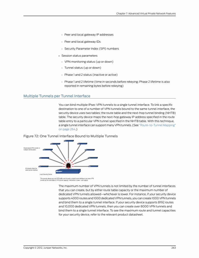
• Peer and local gateway IP addresses
• Peer and local gateway IDs
• Security Parameter Index (SPI) numbers
• Session status parameters
• VPN monitoring status (up or down)
• Tunnel status (up or down)
• Phase 1 and 2 status (inactive or active)
• Phase 1 and 2 lifetime (time in seconds before rekeying; Phase 2 lifetime is also
reported in remaining bytes before rekeying)
Multiple Tunnels per Tunnel Interface
You can bind multiple IPsec VPN tunnels to a single tunnel interface. To link a specific
destination to one of a number of VPN tunnels bound to the same tunnel interface, the
security device uses two tables: the route table and the next-hop tunnel binding (NHTB)
table. The security device maps the next-hop gateway IP address specified in the route
table entry to a particular VPN tunnel specified in the NHTB table. With this technique,
a single tunnel interface can support many VPN tunnels. (See “Route-to-Tunnel Mapping”
on page 264.)
Figure 72: One Tunnel Interface Bound toMultiple Tunnels
The maximum number of VPN tunnels is not limited by the number of tunnel interfaces
that you can create, but by either route table capacity or the maximum number of
dedicated VPN tunnels allowed—whichever is lower. For instance, if your security device
supports 4000 routes and 1000 dedicated VPN tunnels, you can create 1000 VPN tunnels
and bind them to a single tunnel interface. If your security device supports 8192 routes
and 10,000 dedicated VPN tunnels, then you can create over 8000 VPN tunnels and
bind them to a single tunnel interface. To see the maximum route and tunnel capacities
for your security device, refer to the relevant product datasheet.
263Copyright © 2012, Juniper Networks, Inc.
Chapter 7: Advanced Virtual Private Network Features

NOTE: If route-table capacity is the limiting factor, youmust subtract theroutes automatically generated by security zone interfaces and any otherstatic routes—suchas the route to thedefault gateway—that youmight needto define from the total available for route-based VPN tunnels.
Route-to-Tunnel Mapping
To sort traffic among multiple VPN tunnels bound to the same tunnel interface, the
security device maps the next-hop gateway IP address specified in the route to a particular
VPN tunnel name. The mapping of entries in the route table to entries in the NHTB table
is shown below. In Figure 73 on page 264, the local security device routes traffic sent from
10.2.1.5 to 10.1.1.5 through the tunnel.1 interface and then through vpn2.
Figure 73: Route Table and Next-Hop Tunnel Binding (NHTB) Table
The security device uses the IP address of the remote peer’s tunnel interface as the
gateway and next-hop IP address. You can enter the route manually, or you can allow a
dynamic routing protocol to enter a route referencing the peer’s tunnel interface IP address
as the gateway in the route table automatically. The same IP address must also be
entered as the next hop, along with the appropriate VPN tunnel name, in the NHTB table.
Again, there are two options: you can either enter it manually, or you can allow the security
Copyright © 2012, Juniper Networks, Inc.264
Virtual Private Networks

device to obtain it from the remote peer during Phase 2 negotiations and enter it
automatically.
The security device uses the gateway IP address in the route table entry and the next-hop
IP address in the NHTB table entry as the common element to link the tunnel interface
with the corresponding VPN tunnel. The security device can then direct traffic destined
for the IP-prefix specified in the route with the correct VPN tunnel specified in the NHTB
table.
Remote Peers’ Addresses
The internal addressing scheme for all remote peers reached through route-based VPNs
must be unique among each other. One way to accomplish this is for each remote peer
to perform Network Address Translation (NAT) for the source and destination addresses.
In addition, the tunnel interface IP addresses must also be unique among all remote
peers. If you intend to connect to large numbers of remote sites, an address plan becomes
imperative. The following is a possible addressing plan for up to 1000 VPN tunnels:
VPN Tunnel
Gateway/Next-Hop(Peer’s TunnelInterface)
Local TunnelInterface
Dst in LocalRoute Table
vpn110.0.2.1/24tunnel.110.0.3.0/24
vpn210.0.4.1/24tunnel.110.0.5.0/24
vpn310.0.6.1/24tunnel.110.0.7.0/24
…………
vpn12510.0.250.1/24tunnel.110.0.251.0/24
vpn12610.1.2.1/24tunnel.110.1.3.0/24
vpn12710.1.4.1/24tunnel.110.1.5.0/24
vpn12810.1.6.1/24tunnel.110.1.7.0/24
…………
vpn25010.1.250.1/24tunnel.110.1.251.0/24
vpn25110.2.2.1/24tunnel.110.2.3.0/24
…………
vpn37510.2.250.1/24tunnel.110.2.251.0/24
265Copyright © 2012, Juniper Networks, Inc.
Chapter 7: Advanced Virtual Private Network Features

VPN Tunnel
Gateway/Next-Hop(Peer’s TunnelInterface)
Local TunnelInterface
Dst in LocalRoute Table
…………
vpn87610.7.2.1/24tunnel.110.7.3.0/24
…………
vpn100010.7.250.1/24tunnel.110.7.251.0/24
The tunnel interface on the local security device: is 10.0.0.1/24. On all remote hosts, there
is a tunnel interface with an IP address, which appears as the gateway/next-hop IP
address in the local route table and NHTB table.
For an example illustrating multiple tunnels bound to a single tunnel interface with
address translation, see “Setting VPNs on a Tunnel Interface to Overlapping Subnets”
on page 268.
Figure 74: Multiple Tunnels Bound to a Single Tunnel Interface with Address Translation
Manual and Automatic Table Entries
You can make entries in the NHTB and route tables manually. You can also automate
the populating of the NHTB and route tables. For a small number of tunnels bound to a
single tunnel interface, the manual method works well. For a large number of tunnels,
the automatic method reduces administrative setup and maintenance as the routes
dynamically self-adjust if tunnels or interfaces become unavailable on the tunnel interface
at the hub site.
Manual Table Entries
You can manually map a VPN tunnel to the IP address of a remote peer’s tunnel interface
in the next-hop tunnel binding (NHTB) table. First, you must contact the remote admin
and learn the IP address used for the tunnel interface at that end of a tunnel. Then, you
can associate that address with the VPN tunnel name in the NHTB table with the following
command:
set interface tunnel.1 nhtb peer’s_tunnel_interface_addr vpnname_str
Copyright © 2012, Juniper Networks, Inc.266
Virtual Private Networks

After that, you can enter a static route in the route table that uses that tunnel interface
IP address as the gateway. You can enter the route either through the WebUI or through
the following CLI command:
setvroutername_str routedst_addr interfacetunnel.1gatewaypeer’s_tunnel_interface_addr
Automatic Table Entries
To make the population of both the NHTB and route tables automatic, the following
conditions must be met:
• The remote peers for all VPN tunnels bound to a single local tunnel interface must be
security devices running ScreenOS 5.0.0 or later.
• Each remote peer must bind its tunnel to a tunnel interface, and that interface must
have an IP address unique among all peer tunnel interface addresses.
• At both ends of each VPN tunnel, enable VPN monitoring with the rekey option, or
enable the IKE heartbeat reconnect option for each remote gateway.
• The local and remote peers must have an instance of a dynamic routing protocol
enabled on their connecting tunnel interfaces.
The use of VPN monitoring with the rekey option allows the security devices at both ends
of a tunnel to set up the tunnel without having to wait for user-originated VPN traffic.
After you enable VPN monitoring with the rekey option at both ends of a VPN tunnel, the
two security devices perform Phase 1 and Phase 2 IKE negotiations to establish the tunnel.
(For more information, see “VPN Monitoring” on page 251.)
NOTE: If youare runningadynamic routingprotocol on the tunnel interfaces,traffic generated by the protocol can trigger IKE negotiations even withoutenablingVPNmonitoringwith the rekey option or enabling the IKEheartbeatreconnect option. Still, we recommend that you not rely on dynamic routingtraffic to trigger IKE negotiations. Instead use VPNmonitoringwith the rekeyoption or the IKE heartbeat reconnect option.
ForOpenShortestPathFirst (OSPF), youmustconfigure the tunnel interfaceon the local peer as a point-to-multipoint interface before you enable therouting protocol on the interface.
For remote peers with a dynamically assigned external IP address or with afully qualified domain name (FQDN)mapped to a dynamic IP address, theremote peermust first initiate IKE negotiations. However, because thePhase2 SA on the local security device caches the remote peer’s dynamicallyassigned IP address, either peer can reinitiate IKE negotiations to reestablisha tunnel whose VPNmonitoring state has changed from up to down.
During Phase 2 negotiations, the security devices exchange tunnel interface IP addresses
with each other. Each IKE module can then automatically enter the tunnel interface IP
address and its corresponding VPN tunnel name in the NHTB table.
267Copyright © 2012, Juniper Networks, Inc.
Chapter 7: Advanced Virtual Private Network Features

To enable the local security device to enter routes to remote destinations automatically
in its route table, you must enable an instance of BGP on the local and remote tunnel
interfaces. The basic steps are as follows:
1. Create a BGP routing instance on the virtual router that contains the tunnel interface
to which you have bound multiple VPN tunnels.
2. Enable the routing instance on the virtual router.
3. Enable the routing instance on the tunnel interface leading to the BPG peers.
The remote peers also perform these steps.
On the local (or hub) device, you must also define a default route and a static route to
each peer’s tunnel interface IP address. Static routes to the peers’ tunnel interfaces are
necessary for the hub device to reach its BGP neighbors initially through the correct VPN
tunnel.
After establishing communications, the BGP neighbors exchange routing information so
that they can each automatically populate their route tables. After the two peers establish
a VPN tunnel between themselves, the remote peers can send and receive routing
information to and from the local device. When the dynamic routing instance on the local
security device learns a route to a peer through a local tunnel interface, it includes the IP
address of the remote peer’s tunnel interface as the gateway in the route.
For an example illustrating the configuration of multiple tunnels bound to a single tunnel
interface where the “hub” device populates its NHTB and route tables automatically, see
“Binding Automatic Route and NHTB Table Entries” on page 285.
Setting VPNs on a Tunnel Interface to Overlapping Subnets
In this example, you bind three route-based AutoKey IKE VPN tunnels—vpn1, vpn2, and
vpn3—to a single tunnel interface—tunnel.1. The tunnels lead from Device A to three
remote peers—peer1, peer2, and peer3. You manually add both the route table and NHTB
table entries on Device A for all three peers. To see a configuration that provides an
automatic means of populating the route and NHTB tables, see “Binding Automatic
Route and NHTB Table Entries” on page 285.
Figure 75: Tunnel.1 interface Bound to Three VPN Tunnels
ethernet31.1.1.1/24
external router1.1.1.250
Trust zone for Device-A not shown.
Trust Zoneethernet110.1.1.1/24
tunnel.110.0.0.1/30DIP Pool 5:
10.0.0.2 - 10.0.0.2
vpn1IKE gateway: peer1, 2.2.2.2
remote peer’s tunnel interface: 10.0.2.1
vpn2IKE gateway: peer2, 3.3.3.3
remote peer’stunnel interface: 10.0.4.1
vpn3IKE gateway: peer3, 4.4.4.4
remote peer’s tunnel interface: 10.0.6.1
Untrust Zonepeer1
peer2
peer3
vpn1
vpn2
vpn3
Device-ALAN
LAN
LAN
ethernet31.1.1.1/24
external router1.1.1.250
The VPN tunnel configurations at both ends of each tunnel use the following parameters:
• AutoKey IKE
Copyright © 2012, Juniper Networks, Inc.268
Virtual Private Networks

• Preshared key for each peer:
• peer1 uses “netscreen1”
• peer2 uses “netscreen2”
• peer3 uses “netscreen3”
• Security level predefined as “Compatible” for both Phase 1 and Phase 2 proposals. (For
details about these proposals, see “Tunnel Negotiation” on page 11.)
All security zones and interfaces on each device are in the trust-vr virtual routing domain
for that device.
This example uses the same address space—10.1.1.0/24—for every LAN to show how you
can use Source Network Address Translation (NAT-src) and Destination Network Address
Translation (NAT-dst) to overcome addressing conflicts among IPsec peers. For more
information about NAT-src and NAT-dst, see Address Translation.
WebUI (Device A)
1. Interfaces
Network > Interfaces > Edit (for ethernet1): Enter the following, then click Apply:
Zone Name: TrustStatic IP: (select this option when present)IP Address/Netmask: 10.1.1.1/24Enter the following, then clickOK:Interface Mode: NAT
Network > Interfaces > Edit (for ethernet3): Enter the following, then click OK:
Zone Name: UntrustStatic IP: (select this option when present)IP Address/Netmask: 1.1.1.1/24
Network > Interfaces > New Tunnel IF: Enter the following, then click OK:
Tunnel Interface Name: tunnel.1Zone (VR): Untrust (trust-vr)Fixed IP: (select)IP Address / Netmask: 10.0.0.1/30
Network > Interfaces > Edit (for tunnel.1) > DIP > New: Enter the following, then click
OK:
ID: 5IP Address Range: (select), 10.0.0.2 ~ 10.0.0.2Port Translation: (select)
In the same subnet as the interface IP or its secondary IPs: (select)
2. Addresses
Policy > Policy Elements > Addresses > List > New: Enter the following, then clickOK:
Address Name: corpIP Address/Domain Name:IP/Netmask: (select), 10.1.1.0/24
Zone: Trust
269Copyright © 2012, Juniper Networks, Inc.
Chapter 7: Advanced Virtual Private Network Features
Policy > Policy Elements > Addresses > List > New: Enter the following, then clickOK:
Address Name: oda1IP Address/Domain Name:IP/Netmask: (select), 10.0.1.0/24
Zone: Trust
Policy > Policy Elements > Addresses > List > New: Enter the following, then clickOK:
Address Name: peersIP Address/Domain Name:IP/Netmask: (select), 10.0.0.0/16
Zone: Untrust
3. VPNs
VPNs > AutoKey IKE > New: Enter the following, then click OK:
VPNName: vpn1Security Level: CompatibleRemote Gateway: Create a Simple Gateway: (select)Gateway Name: peer1Type: Static IP: (select), Address/Hostname: 2.2.2.2Preshared Key: netscreen1Security Level: CompatibleOutgoing Interface: ethernet3
> Advanced: Enter the following advanced settings, then click Return to return to the
basic AutoKey IKE configuration page:
Bind to: Tunnel Interface, tunnel.1Proxy-ID: (select)Local IP / Netmask: 0.0.0.0/0Remote IP / Netmask: 0.0.0.0/0Service: ANY
VPNs > AutoKey IKE > New: Enter the following, then click OK:
VPNName: vpn2Security Level: CompatibleRemote Gateway: Create a Simple Gateway: (select)Gateway Name: peer2Type: Static IP: (select), Address/Hostname: 3.3.3.3Preshared Key: netscreen2Security Level: CompatibleOutgoing Interface: ethernet3
> Advanced: Enter the following advanced settings, then click Return to return to the
basic AutoKey IKE configuration page:
Bind to: Tunnel Interface, tunnel.1Proxy-ID: (select)Local IP / Netmask: 0.0.0.0/0Remote IP / Netmask: 0.0.0.0/0Service: ANY
VPNs > AutoKey IKE > New: Enter the following, then click OK:
VPNName: vpn3Security Level: CompatibleRemote Gateway: Create a Simple Gateway: (select)
Copyright © 2012, Juniper Networks, Inc.270
Virtual Private Networks

Gateway Name: peer3Type: Static IP: (select), Address/Hostname: 4.4.4.4Preshared Key: netscreen3Security Level: CompatibleOutgoing Interface: ethernet3
> Advanced: Enter the following advanced settings, then click Return to return to the
basic AutoKey IKE configuration page:
Bind to: Tunnel Interface, tunnel.1Proxy-ID: (select)Local IP / Netmask: 0.0.0.0/0Remote IP / Netmask: 0.0.0.0/0Service: ANY
4. Routes
Network > Routing > Routing Entries > (trust-vr) New: Enter the following, then click
OK:
Network Address / Netmask: 0.0.0.0/0Gateway: (select)Interface: ethernet3Gateway IP Address: 1.1.1.250
Network > Routing > Routing Entries > (trust-vr) New: Enter the following, then click
OK:
Network Address / Netmask: 10.0.1.0/24Gateway: (select)Interface: ethernet1Gateway IP Address: 0.0.0.0
Network > Routing > Routing Entries > (trust-vr) New: Enter the following, then click
OK:
Network Address / Netmask: 10.0.3.0/24Gateway: (select)Interface: tunnel.1Gateway IP Address: 10.0.2.1
Network > Routing > Routing Entries > (trust-vr) New: Enter the following, then click
OK:
Network Address / Netmask: 10.0.2.2/32Gateway: (select)Interface: tunnel.1Gateway IP Address: 10.0.2.1
Network > Routing > Routing Entries > (trust-vr) New: Enter the following, then click
OK:
Network Address / Netmask: 10.0.5.0/24Gateway: (select)Interface: tunnel.1Gateway IP Address: 10.0.4.1
Network > Routing > Routing Entries > (trust-vr) New: Enter the following, then click
OK:
271Copyright © 2012, Juniper Networks, Inc.
Chapter 7: Advanced Virtual Private Network Features

Network Address / Netmask: 10.0.4.2/32Gateway: (select)Interface: tunnel.1Gateway IP Address: 10.0.4.1
Network > Routing > Routing Entries > (trust-vr) New: Enter the following, then click
OK:
Network Address / Netmask: 10.0.7.0/24Gateway: (select)Interface: tunnel.1Gateway IP Address: 10.0.6.1
Network > Routing > Routing Entries > (trust-vr) New: Enter the following, then click
OK:
Network Address / Netmask: 10.0.6.2/32Gateway: (select)Interface: tunnel.1Gateway IP Address: 10.0.6.1
Network > Routing > Routing Entries > (trust-vr) New: Enter the following, then click
OK:
Network Address / Netmask: 10.0.0.0/16Gateway: (select)Interface: nullGateway IP Address: 0.0.0.0Metric: 10
Network > Interfaces > Edit (for tunnel.1) > NHTB > New: Enter the following, then
click Add:
NewNext Hop Entry:IP Address: 10.0.2.1VPN: vpn1
Network > Interfaces > Edit (for tunnel.1) > NHTB: Enter the following, then clickAdd:
NewNext Hop Entry:IP Address: 10.0.4.1VPN: vpn2
Network > Interfaces > Edit (for tunnel.1) > NHTB: Enter the following, then clickAdd:
NewNext Hop Entry:IP Address: 10.0.6.1VPN: vpn3
5. Policies
Policies > (From: Trust, To: Untrust) New: Enter the following, then click OK:
Source Address:Address Book: (select), corp
Destination Address:Address Book: (select), peers
Service: AnyAction: PermitPosition at Top: (select)
Copyright © 2012, Juniper Networks, Inc.272
Virtual Private Networks

> Advanced: Enter the following advanced settings, then click Return to return to the
basic Policy configuration page:
NAT:Source Translation: (select)DIP On: 5 (10.0.0.2–10.0.0.2)/X-late
Policies > (From: Untrust, To: Trust) New: Enter the following, then click OK:
Source Address:Address Book Entry: (select), peers
Destination Address:Address Book Entry: (select), oda1
Service: AnyAction: PermitPosition at Top: (select)
> Advanced: Enter the following advanced settings, then click Return to return to the
basic Policy configuration page:
NAT:Destination Translation: (select)Translate to IP Range: (select), 10.1.1.0 - 10.1.1.254
CLI (Device A)
1. Interfaces
set interface ethernet1 zone trustset interface ethernet1 ip 10.1.1.1/24set interface ethernet3 zone untrustset interface ethernet3 ip 1.1.1.1/24set interface tunnel.1 zone untrustset interface tunnel.1 ip 10.0.0.1/30set interface tunnel.1 dip 5 10.0.0.2 10.0.0.2
2. Addresses
set address trust corp 10.1.1.0/24set address trust oda1 10.0.1.0/24set address untrust peers 10.0.0.0/16
3. VPNs
set ikegatewaypeer1address2.2.2.2outgoing-interfaceethernet3presharenetscreen1sec-level compatibleset vpn vpn1 gateway peer1 sec-level compatibleset vpn vpn1 bind interface tunnel.1set vpn vpn1 proxy-id local-ip 0.0.0.0/0 remote-ip 0.0.0.0/0 anyset ikegatewaypeer2address3.3.3.3outgoing-interfaceethernet3presharenetscreen2sec-level compatibleset vpn vpn2 gateway peer2 sec-level compatibleset vpn vpn2 bind interface tunnel.1set vpn vpn2 proxy-id local-ip 0.0.0.0/0 remote-ip 0.0.0.0/0 anyset ike gateway peer3 address 4.4.4.4 outgoing-interface ethernet3 presharenetscreen3 sec-level compatibleset vpn vpn3 gateway peer3 sec-level compatibleset vpn vpn3 bind interface tunnel.1set vpn vpn3 proxy-id local-ip 0.0.0.0/0 remote-ip 0.0.0.0/0 any
273Copyright © 2012, Juniper Networks, Inc.
Chapter 7: Advanced Virtual Private Network Features

4. Routes
set vrouter trust-vr route 0.0.0.0/0 interface ethernet3 gateway 1.1.1.250set vrouter trust-vr route 10.0.1.0/24 interface ethernet1set vrouter trust-vr route 10.0.3.0/24 interface tunnel.1 gateway 10.0.2.1set vrouter trust-vr route 10.0.2.2/32 interface tunnel.1 gateway 10.0.2.1set vrouter trust-vr route 10.0.5.0/24 interface tunnel.1 gateway 10.0.4.1set vrouter trust-vr route 10.0.4.2/32 interface tunnel.1 gateway 10.0.4.1set vrouter trust-vr route 10.0.7.0/24 interface tunnel.1 gateway 10.0.6.1set vrouter trust-vr route 10.0.6.2/32 interface tunnel.1 gateway 10.0.6.1set vrouter trust-vr route 10.0.0.0/16 interface null metric 10set interface tunnel.1 nhtb 10.0.2.1 vpn vpn1set interface tunnel.1 nhtb 10.0.4.1 vpn vpn2set interface tunnel.1 nhtb 10.0.6.1 vpn vpn3
5. Policies
set policy from trust to untrust corp peers any nat src dip-id 5 permitset policy from untrust to trust peers oda1 any nat dst ip 10.1.1.0 10.1.1.254 permitsave
Peer1
The following configuration, as illustrated in Figure 76 on page 274, is what the remote
admin for the security device at the peer1 site must enter to create a VPN tunnel to
Device A at the corporate site. The remote admin configures the security device to perform
source and destination NAT (NAT-src and NAT-dst) because the internal addresses are
in the same address space as those in the corporate LAN: 10.1.1.0/24. Peer1 performs
NAT-src using DIP pool 6 to translate all internal source addresses to 10.0.2.2 when
sending traffic through VPN1 to Device A. Peer1 performs NAT-dst on VPN traffic sent
from Device A, translating addresses from 10.0.3.0/24 to 10.1.1.0/24 with address shifting
in effect.
Figure 76: Peer1 Performing NAT-Dst
NOTE: For more information about NAT-src and NAT-dst, see AddressTranslation.
WebUI (Peer1)
1. Interfaces
Network > Interfaces > Edit (for ethernet1): Enter the following, then click Apply:
Copyright © 2012, Juniper Networks, Inc.274
Virtual Private Networks

Zone Name: TrustStatic IP: (select this option when present)IP Address/Netmask: 10.1.1.1/24Enter the following, then clickOK:Interface Mode: NAT
Network > Interfaces > Edit (for ethernet3): Enter the following, then click OK:
Zone Name: UntrustStatic IP: (select this option when present)IP Address/Netmask: 2.2.2.2/24
Network > Interfaces > New Tunnel IF: Enter the following, then click OK:
Tunnel Interface Name: tunnel.10Zone (VR): Untrust (trust-vr)Fixed IP: (select)IP Address / Netmask: 10.0.2.1/30
Network > Interfaces > Edit (for tunnel.10) > DIP > New: Enter the following, then click
OK:
ID: 6IP Address Range: (select), 10.0.2.2 ~ 10.0.2.2Port Translation: (select)
In the same subnet as the interface IP or its secondary IPs: (select)
2. Addresses
Policy > Policy Elements > Addresses > List > New: Enter the following, then clickOK:
Address Name: lanIP Address/Domain Name:IP/Netmask: (select), 10.1.1.0/24
Zone: Trust
Policy > Policy Elements > Addresses > List > New: Enter the following, then clickOK:
Address Name: oda2IP Address/Domain Name:IP/Netmask: (select), 10.0.3.0/24
Zone: Trust
Policy > Policy Elements > Addresses > List > New: Enter the following, then clickOK:
Address Name: to_corpIP Address/Domain Name:IP/Netmask: (select), 10.0.1.0/24
Zone: Untrust
Policy > Policy Elements > Addresses > List > New: Enter the following, then clickOK:
Address Name: fr_corpIP Address/Domain Name:IP/Netmask: (select), 10.0.0.2/32
Zone: Untrust
3. VPN
VPNs > AutoKey IKE > New: Enter the following, then click OK:
275Copyright © 2012, Juniper Networks, Inc.
Chapter 7: Advanced Virtual Private Network Features

VPNName: vpn1Security Level: CompatibleRemote Gateway: Create a Simple Gateway: (select)Gateway Name: corpType: Static IP: (select), Address/Hostname: 1.1.1.1Preshared Key: netscreen1Security Level: CompatibleOutgoing Interface: ethernet3
> Advanced: Enter the following advanced settings, then click Return to return to the
basic AutoKey IKE configuration page:
Bind to: Tunnel Interface, tunnel.10Proxy-ID: (select)Local IP / Netmask: 0.0.0.0/0Remote IP / Netmask: 0.0.0.0/0Service: ANY
4. Routes
Network > Routing > Routing Entries > (trust-vr) New: Enter the following, then click
OK:
Network Address / Netmask: 0.0.0.0/0Gateway: (select)Interface: ethernet3Gateway IP Address: 2.2.2.250Metric: 1
Network > Routing > Routing Entries > (trust-vr) New: Enter the following, then click
OK:
Network Address / Netmask: 10.0.3.0/24Gateway: (select)Interface: ethernet1Gateway IP Address: 0.0.0.0Metric: 1
Network > Routing > Routing Entries > (trust-vr) New: Enter the following, then click
OK:
Network Address / Netmask: 10.0.0.0/8Gateway: (select)Interface: tunnel.10Gateway IP Address: 0.0.0.0Metric: 10
Network > Routing > Routing Entries > (trust-vr) New: Enter the following, then click
OK:
Network Address / Netmask: 10.0.0.0/8Gateway: (select)Interface: nullGateway IP Address: 0.0.0.0Metric: 12
5. Policies
Policies > (From: Untrust, To: Trust) New: Enter the following, then click OK:
Copyright © 2012, Juniper Networks, Inc.276
Virtual Private Networks
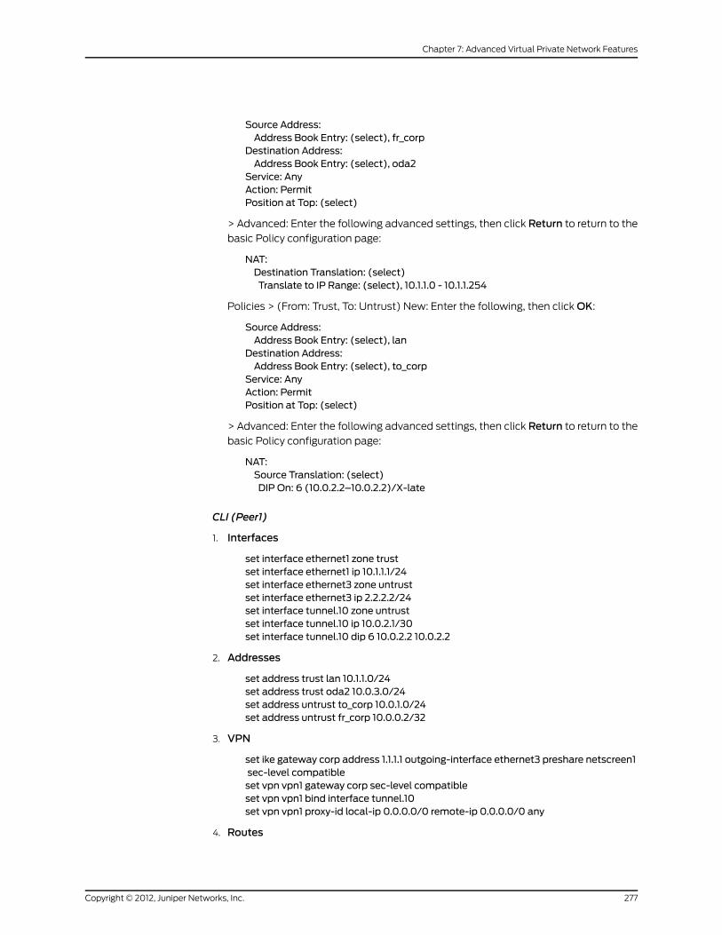
Source Address:Address Book Entry: (select), fr_corp
Destination Address:Address Book Entry: (select), oda2
Service: AnyAction: PermitPosition at Top: (select)
> Advanced: Enter the following advanced settings, then click Return to return to the
basic Policy configuration page:
NAT:Destination Translation: (select)Translate to IP Range: (select), 10.1.1.0 - 10.1.1.254
Policies > (From: Trust, To: Untrust) New: Enter the following, then click OK:
Source Address:Address Book Entry: (select), lan
Destination Address:Address Book Entry: (select), to_corp
Service: AnyAction: PermitPosition at Top: (select)
> Advanced: Enter the following advanced settings, then click Return to return to the
basic Policy configuration page:
NAT:Source Translation: (select)DIP On: 6 (10.0.2.2–10.0.2.2)/X-late
CLI (Peer1)
1. Interfaces
set interface ethernet1 zone trustset interface ethernet1 ip 10.1.1.1/24set interface ethernet3 zone untrustset interface ethernet3 ip 2.2.2.2/24set interface tunnel.10 zone untrustset interface tunnel.10 ip 10.0.2.1/30set interface tunnel.10 dip 6 10.0.2.2 10.0.2.2
2. Addresses
set address trust lan 10.1.1.0/24set address trust oda2 10.0.3.0/24set address untrust to_corp 10.0.1.0/24set address untrust fr_corp 10.0.0.2/32
3. VPN
set ike gateway corp address 1.1.1.1 outgoing-interface ethernet3 preshare netscreen1sec-level compatibleset vpn vpn1 gateway corp sec-level compatibleset vpn vpn1 bind interface tunnel.10set vpn vpn1 proxy-id local-ip 0.0.0.0/0 remote-ip 0.0.0.0/0 any
4. Routes
277Copyright © 2012, Juniper Networks, Inc.
Chapter 7: Advanced Virtual Private Network Features

set vrouter trust-vr route 0.0.0.0/0 interface ethernet3 gateway 2.2.2.250metric 1set vrouter trust-vr route 10.0.3.0/24 interface ethernet1 metric 1set vrouter trust-vr route 10.0.0.0/8 interface tunnel.10metric 10set vrouter trust-vr route 10.0.0.0/8 interface null metric 12
5. Policies
set policy from trust to untrust lan to_corp any nat src dip-id 6 permitset policy from untrust to trust fr_corp oda2 any nat dst ip 10.1.1.0 10.1.1.254 permitsave
Peer2
The following configuration, as illustrated in Figure 77 on page 278, is what the remote
admin for the security device at the peer2 site must enter to create a VPN tunnel to
Device A at the corporate site. The remote admin configures the security device to perform
source and destination NAT (NAT-src and NAT-dst) because the internal addresses are
in the same address space as those in the corporate LAN: 10.1.1.0/24. Peer2 performs
NAT-src using DIP pool 7 to translate all internal source addresses to 10.0.4.2 when
sending traffic through VPN2 to Device A. Peer2 performs NAT-dst on VPN traffic sent
from Device A, translating addresses from 10.0.5.0/24 to 10.1.1.0/24 with address shifting
in effect.
Figure 77: Peer2
NOTE: For more information about NAT-src and NAT-dst, see AddressTranslation.
WebUI (Peer2)
1. Interfaces
Network > Interfaces > Edit (for ethernet1): Enter the following, then click Apply:
Zone Name: TrustStatic IP: (select this option when present)IP Address/Netmask: 10.1.1.1/24Enter the following, then clickOK:Interface Mode: NAT
Network > Interfaces > Edit (for ethernet3): Enter the following, then click OK:
Copyright © 2012, Juniper Networks, Inc.278
Virtual Private Networks

Zone Name: UntrustStatic IP: (select this option when present)IP Address/Netmask: 3.3.3.3/24
Network > Interfaces > New Tunnel IF: Enter the following, then click OK:
Tunnel Interface Name: tunnel.20Zone (VR): Untrust (trust-vr)Fixed IP: (select)IP Address / Netmask: 10.0.4.1/30
Network > Interfaces > Edit (for tunnel.20) > DIP > New: Enter the following, then
click OK:
ID: 7IP Address Range: (select), 10.0.4.2 ~ 10.0.4.2Port Translation: (select)
In the same subnet as the interface IP or its secondary IPs: (select)
2. Addresses
Policy > Policy Elements > Addresses > List > New: Enter the following, then clickOK:
Address Name: lanIP Address/Domain Name:IP/Netmask: (select), 10.1.1.0/24
Zone: Trust
Policy > Policy Elements > Addresses > List > New: Enter the following, then clickOK:
Address Name: oda3IP Address/Domain Name:IP/Netmask: (select), 10.0.5.0/24
Zone: Trust
Policy > Policy Elements > Addresses > List > New: Enter the following, then clickOK:
Address Name: to_corpIP Address/Domain Name:IP/Netmask: (select), 10.0.1.0/24
Zone: Untrust
Policy > Policy Elements > Addresses > List > New: Enter the following, then clickOK:
Address Name: fr_corpIP Address/Domain Name:IP/Netmask: (select), 10.0.0.2/32
Zone: Untrust
3. VPN
VPNs > AutoKey IKE > New: Enter the following, then click OK:
VPNName: vpn2Security Level: CompatibleRemote Gateway: Create a Simple Gateway: (select)Gateway Name: corpType: Static IP: (select), Address/Hostname: 1.1.1.1Preshared Key: netscreen2Security Level: CompatibleOutgoing Interface: ethernet3
279Copyright © 2012, Juniper Networks, Inc.
Chapter 7: Advanced Virtual Private Network Features

> Advanced: Enter the following advanced settings, then click Return to return to the
basic AutoKey IKE configuration page:
Bind to: Tunnel Interface, tunnel.20Proxy-ID: (select)Local IP / Netmask: 0.0.0.0/0Remote IP / Netmask: 0.0.0.0/0Service: ANY
4. Routes
Network > Routing > Routing Entries > (trust-vr) New: Enter the following, then click
OK:
Network Address / Netmask: 0.0.0.0/0Gateway: (select)Interface: ethernet3Gateway IP Address: 3.3.3.250Metric: 1
Network > Routing > Routing Entries > (trust-vr) New: Enter the following, then click
OK:
Network Address / Netmask: 10.0.5.0/24Gateway: (select)Interface: ethernet1Gateway IP Address: 0.0.0.0Metric: 1
Network > Routing > Routing Entries > (trust-vr) New: Enter the following, then click
OK:
Network Address / Netmask: 10.0.1.0/24Gateway: (select)Interface: tunnel.20Gateway IP Address: 0.0.0.0Metric: 10
Network > Routing > Routing Entries > (trust-vr) New: Enter the following, then click
OK:
Network Address / Netmask: 10.0.1.0/24Gateway: (select)Interface: nullGateway IP Address: 0.0.0.0Metric: 12
5. Policies
Policies > (From: Trust, To: Untrust) New: Enter the following, then click OK:
Source Address:Address Book Entry: (select), lan
Destination Address:Address Book Entry: (select), to_corp
Service: AnyAction: PermitPosition at Top: (select)
Copyright © 2012, Juniper Networks, Inc.280
Virtual Private Networks

> Advanced: Enter the following advanced settings, then click Return to return to the
basic Policy configuration page:
NAT:Source Translation: (select)DIP On: 7 (10.0.4.2–10.0.4.2)/X-late
Policies > (From: Untrust, To: Trust) New: Enter the following, then click OK:
Source Address:Address Book Entry: (select), fr_corp
Destination Address:Address Book Entry: (select), oda3
Service: AnyAction: PermitPosition at Top: (select)
> Advanced: Enter the following advanced settings, then click Return to return to the
basic Policy configuration page:
NAT:Destination Translation: (select)Translate to IP Range: (select), 10.1.1.0 - 10.1.1.254
CLI (Peer2)
1. Interfaces
set interface ethernet1 zone trustset interface ethernet1 ip 10.1.1.1/24set interface ethernet3 zone untrustset interface ethernet3 ip 3.3.3.3/24set interface tunnel.20 zone untrustset interface tunnel.20 ip 10.0.4.1/30set interface tunnel.20 dip 7 10.0.4.2 10.0.4.2
2. Addresses
set address trust lan 10.1.1.0/24set address trust oda3 10.0.5.0/24set address untrust to_corp 10.0.1.0/24set address untrust fr_corp 10.0.0.2/32
3. VPN
set ike gateway corp address 1.1.1.1 outgoing-interface ethernet3 preshare netscreen2sec-level compatibleset vpn vpn2 gateway corp sec-level compatibleset vpn vpn2 bind interface tunnel.20set vpn vpn2 proxy-id local-ip 0.0.0.0/0 remote-ip 0.0.0.0/0 any
4. Routes
set vrouter trust-vr route 0.0.0.0/0 interface ethernet3 gateway 3.3.3.250metric 1set vrouter trust-vr route 10.0.5.0/24 interface ethernet1 metric 1set vrouter trust-vr route 10.0.0.0/8 interface tunnel.20metric 10set vrouter trust-vr route 10.0.0.0/8 interface null metric 12
5. Policies
281Copyright © 2012, Juniper Networks, Inc.
Chapter 7: Advanced Virtual Private Network Features

set policy from trust to untrust lan to_corp any nat src dip-id 7 permitset policy from untrust to trust fr_corp oda3 any nat dst ip 10.1.1.0 10.1.1.254 permitsave
Peer3
The following configuration, as illustrated in Figure 78 on page 282, is what the remote
admin for the security device at the peer3 site must enter to create a VPN tunnel to
Device A at the corporate site. The remote admin configures the security device to perform
source and destination NAT (NAT-src and NAT-dst) because the internal addresses are
in the same address space as those in the corporate LAN: 10.1.1.0/24. Peer3 performs
NAT-src using DIP pool 8 to translate all internal source addresses to 10.0.6.2 when
sending traffic through VPN3 to Device A. Peer3 performs NAT-dst on VPN traffic sent
from Device A, translating addresses from 10.0.7.0/24 to 10.1.1.0/24 with address shifting
in effect.
Figure 78: Peer3
NOTE: For more information about NAT-dst, see Address Translation.
WebUI (Peer3)
1. Interfaces
Network > Interfaces > Edit (for ethernet1): Enter the following, then click Apply:
Zone Name: TrustStatic IP: (select this option when present)IP Address/Netmask: 10.1.1.1/24Enter the following, then clickOK:Interface Mode: NAT
Network > Interfaces > Edit (for ethernet3): Enter the following, then click OK:
Zone Name: UntrustStatic IP: (select this option when present)IP Address/Netmask: 4.4.4.4/24
Network > Interfaces > New Tunnel IF: Enter the following, then click OK:
Tunnel Interface Name: tunnel.30Zone (VR): Untrust (trust-vr)Fixed IP: (select)IP Address / Netmask: 10.0.6.1/30
Copyright © 2012, Juniper Networks, Inc.282
Virtual Private Networks

Network > Interfaces > Edit (for tunnel.320) > DIP > New: Enter the following, then
click OK:
ID: 7IP Address Range: (select), 10.0.6.2 ~ 10.0.6.2Port Translation: (select)
In the same subnet as the interface IP or its secondary IPs: (select)
2. Addresses
Policy > Policy Elements > Addresses > List > New: Enter the following, then clickOK:
Address Name: lanIP Address/Domain Name:IP/Netmask: (select), 10.1.1.0/24
Zone: Trust
Policy > Policy Elements > Addresses > List > New: Enter the following, then clickOK:
Address Name: oda4IP Address/Domain Name:IP/Netmask: (select), 10.0.7.0/24
Zone: Trust
Policy > Policy Elements > Addresses > List > New: Enter the following, then clickOK:
Address Name: to_corpIP Address/Domain Name:IP/Netmask: (select), 10.0.1.0/24
Zone: Untrust
Policy > Policy Elements > Addresses > List > New: Enter the following, then clickOK:
Address Name: fr_corpIP Address/Domain Name:IP/Netmask: (select), 10.0.0.2/32
Zone: Untrust
3. VPN
VPNs > AutoKey IKE > New: Enter the following, then click OK:
VPNName: vpn3Security Level: CompatibleRemote Gateway: Create a Simple Gateway: (select)Gateway Name: corpType: Static IP: (select), Address/Hostname: 1.1.1.1Preshared Key: netscreen3Security Level: CompatibleOutgoing Interface: ethernet3
> Advanced: Enter the following advanced settings, then click Return to return to the
basic AutoKey IKE configuration page:
Bind to: Tunnel Interface, tunnel.30Proxy-ID: (select)Local IP / Netmask: 0.0.0.0/0Remote IP / Netmask: 0.0.0.0/0Service: ANY
4. Routes
283Copyright © 2012, Juniper Networks, Inc.
Chapter 7: Advanced Virtual Private Network Features

Network > Routing > Routing Entries > (trust-vr) New: Enter the following, then click
OK:
Network Address / Netmask: 0.0.0.0/0Gateway: (select)Interface: ethernet3Gateway IP Address: 4.4.4.250Metric: 1
Network > Routing > Routing Entries > (trust-vr) New: Enter the following, then click
OK:
Network Address / Netmask: 10.0.7.0/24Gateway: (select)Interface: ethernet1Gateway IP Address: 0.0.0.0Metric: 1
Network > Routing > Routing Entries > (trust-vr) New: Enter the following, then click
OK:
Network Address / Netmask: 10.0.0.0/8Gateway: (select)Interface: tunnel.20Gateway IP Address: 10.0.0.1Metric: 10
Network > Routing > Routing Entries > (trust-vr) New: Enter the following, then click
OK:
Network Address / Netmask: 10.0.0.0/8Gateway: (select)Interface: nullGateway IP Address: 10.0.0.1Metric: 12
5. Policies
Policies > (From: Trust, To: Untrust) New: Enter the following, then click OK:
Source Address:Address Book Entry: (select), lan
Destination Address:Address Book Entry: (select), to_corp
Service: AnyAction: PermitPosition at Top: (select)
> Advanced: Enter the following advanced settings, then click Return to return to the
basic Policy configuration page:
NAT:Source Translation: (select)DIP On: 8 (10.0.6.2–10.0.6.2)/X-late
Policies > (From: Untrust, To: Trust) New: Enter the following, then click OK:
Source Address:Address Book Entry: (select), fr_corp
Destination Address:
Copyright © 2012, Juniper Networks, Inc.284
Virtual Private Networks
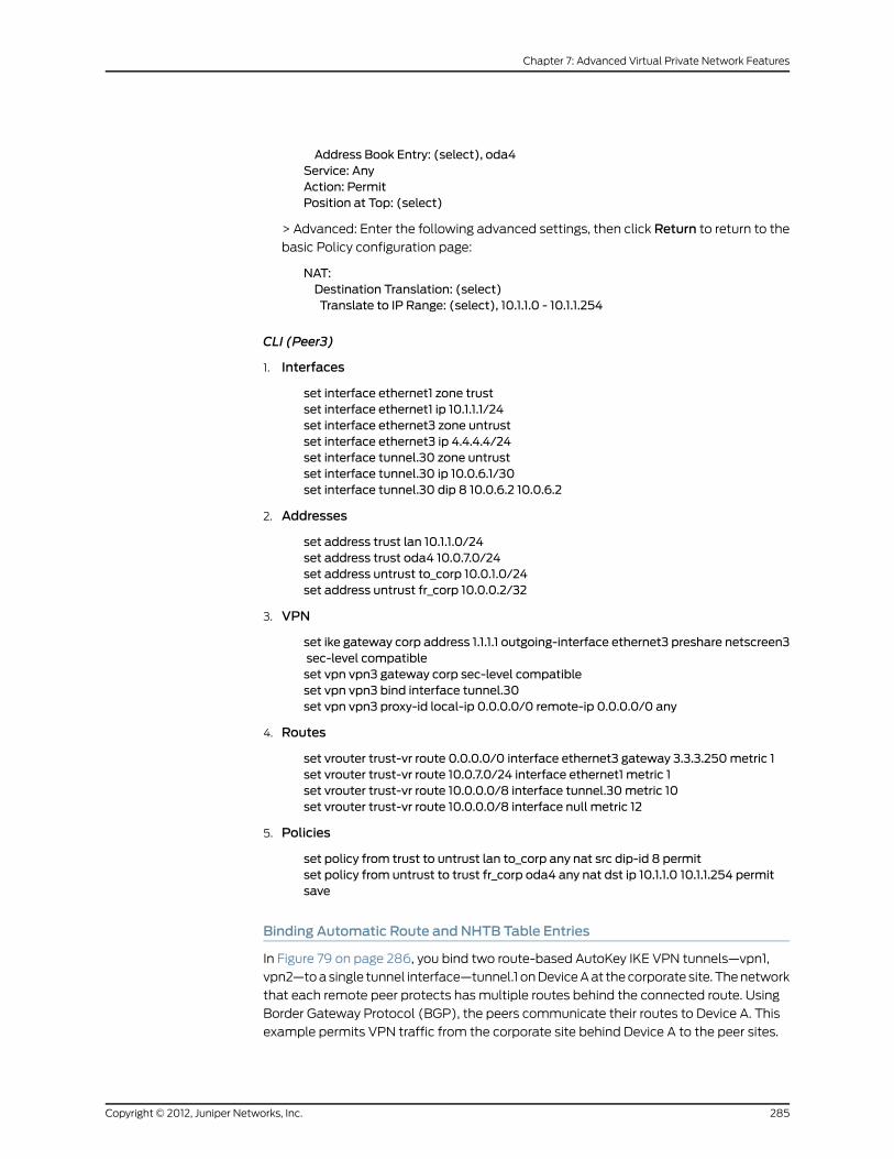
Address Book Entry: (select), oda4Service: AnyAction: PermitPosition at Top: (select)
> Advanced: Enter the following advanced settings, then click Return to return to the
basic Policy configuration page:
NAT:Destination Translation: (select)Translate to IP Range: (select), 10.1.1.0 - 10.1.1.254
CLI (Peer3)
1. Interfaces
set interface ethernet1 zone trustset interface ethernet1 ip 10.1.1.1/24set interface ethernet3 zone untrustset interface ethernet3 ip 4.4.4.4/24set interface tunnel.30 zone untrustset interface tunnel.30 ip 10.0.6.1/30set interface tunnel.30 dip 8 10.0.6.2 10.0.6.2
2. Addresses
set address trust lan 10.1.1.0/24set address trust oda4 10.0.7.0/24set address untrust to_corp 10.0.1.0/24set address untrust fr_corp 10.0.0.2/32
3. VPN
set ike gateway corp address 1.1.1.1 outgoing-interface ethernet3 preshare netscreen3sec-level compatibleset vpn vpn3 gateway corp sec-level compatibleset vpn vpn3 bind interface tunnel.30set vpn vpn3 proxy-id local-ip 0.0.0.0/0 remote-ip 0.0.0.0/0 any
4. Routes
set vrouter trust-vr route 0.0.0.0/0 interface ethernet3 gateway 3.3.3.250metric 1set vrouter trust-vr route 10.0.7.0/24 interface ethernet1 metric 1set vrouter trust-vr route 10.0.0.0/8 interface tunnel.30metric 10set vrouter trust-vr route 10.0.0.0/8 interface null metric 12
5. Policies
set policy from trust to untrust lan to_corp any nat src dip-id 8 permitset policy from untrust to trust fr_corp oda4 any nat dst ip 10.1.1.0 10.1.1.254 permitsave
Binding Automatic Route and NHTB Table Entries
In Figure 79 on page 286, you bind two route-based AutoKey IKE VPN tunnels—vpn1,
vpn2—to a single tunnel interface—tunnel.1 on Device A at the corporate site. The network
that each remote peer protects has multiple routes behind the connected route. Using
Border Gateway Protocol (BGP), the peers communicate their routes to Device A. This
example permits VPN traffic from the corporate site behind Device A to the peer sites.
285Copyright © 2012, Juniper Networks, Inc.
Chapter 7: Advanced Virtual Private Network Features

NOTE: You can also use Open Shortest Path First (OSPF) instead of BGP asthe routing protocol in this example. See “Using OSPF for Automatic RouteTable Entries” on page 296 for the OSPF configurations.
Figure 79: Automatic Route and NHTB Table Entries (Device A)
The VPN tunnel configurations at both ends of each tunnel use the following parameters:
AutoKey IKE, preshared key (peer1: “netscreen1”, peer2: “netscreen2”), and the security
level predefined as “Compatible” for both Phase 1 and Phase 2 proposals. (For details
about these proposals, see “Tunnel Negotiation” on page 11.)
By configuring the following two features, you can enable Device A to populate its NHTB
and route tables automatically:
• VPN monitoring with the rekey option (or the IKE heartbeats reconnect option)
• BGP dynamic routing on tunnel.1
NOTE: If you are running a dynamic routing protocol on the tunnelinterfaces, traffic generated by the protocol can trigger IKE negotiationseven without enabling VPNmonitoring with the rekey option or enablingthe IKE heartbeat reconnect option. Still, Juniper Networks recommendsthat you not rely on dynamic routing traffic to trigger IKE negotiations.Instead use VPNmonitoring with the rekey option or the IKE heartbeatreconnect option.
If you are running BGP on the tunnel interfaces, the BGP-generated trafficcan trigger IKE negotiations even without enabling VPNmonitoring withthe rekeyoptionorenabling the IKEheartbeat reconnectoption.Still, JuniperNetworks recommends that you not rely on BGP traffic to trigger IKEnegotiations. Instead, use VPNmonitoringwith the rekey option or the IKEheartbeat reconnect option.
Copyright © 2012, Juniper Networks, Inc.286
Virtual Private Networks

When you enable VPN monitoring with the rekey option for an AutoKey IKE VPN tunnel,
Device A establishes a VPN connection with its remote peer as soon as you and the admin
at the remote site finish configuring the tunnel. The devices do not wait for user-generated
VPN traffic to perform IKE negotiations. During Phase 2 negotiations, the security devices
exchange their tunnel interface IP address, so that Device A can automatically make a
VPN-to-next-hop mapping in its NHTB table.
The rekey option ensures that when the Phase 1 and Phase 2 key lifetimes expire, the
devices automatically negotiate the generation of new keys without the need for human
intervention. VPN monitoring with the rekey option enabled essentially provides a means
for keeping a VPN tunnel up continually, even when there is no user-generated traffic.
This is necessary so that the BGP dynamic routing instances that you and the remote
admins create and enable on the tunnel interfaces at both ends of the tunnels can send
routing information to Device A and automatically populate its route table with the routes
it needs to direct traffic through the VPN tunnel before those routes are required for
user-generated traffic. (The admins at the peer sites still need to enter a single static
route to the rest of the virtual private network through the tunnel interface at each
respective site.)
You enter a default route and static routes on Device A to reach its BGP neighbors through
the correct VPN tunnels. All security zones and interfaces on each device are in the trust-vr
virtual routing domain for that device.
WebUI (Device A)
1. Interfaces
Network > Interfaces > Edit (for ethernet1): Enter the following, then click Apply:
Zone Name: TrustStatic IP: (select this option when present)IP Address/Netmask: 10.1.1.1/24Enter the following, then clickOK:Interface Mode: NAT
Network > Interfaces > Edit (for ethernet3): Enter the following, then click OK:
Zone Name: UntrustStatic IP: (select this option when present)IP Address/Netmask: 1.1.1.1/24
Network > Interfaces > New Tunnel IF: Enter the following, then click OK:
Tunnel Interface Name: tunnel.1Zone (VR): Untrust (trust-vr)Fixed IP: (select)IP Address / Netmask: 10.0.0.1/30
2. VPNs
VPNs > AutoKey IKE > New: Enter the following, then click OK:
VPNName: vpn1Security Level: CompatibleRemote Gateway: Create a Simple Gateway: (select)Gateway Name: peer1Type: Static IP: (select), Address/Hostname: 2.2.2.2
287Copyright © 2012, Juniper Networks, Inc.
Chapter 7: Advanced Virtual Private Network Features

Preshared Key: netscreen1Security Level: CompatibleOutgoing Interface: ethernet3
> Advanced: Enter the following advanced settings, then click Return to return to the
basic AutoKey IKE configuration page:
Bind to: Tunnel Interface, tunnel.1Proxy-ID: (select)Local IP / Netmask: 0.0.0.0/0Remote IP / Netmask: 0.0.0.0/0Service: ANY
VPNMonitor: (select)Rekey: (select)
NOTE: Leave the Source Interface and Destination IP options at theirdefaultsettings.For informationabout theseoptions, see“VPNMonitoring”on page 251.
VPNs > AutoKey IKE > New: Enter the following, then click OK:
VPNName: vpn2Security Level: CompatibleRemote Gateway: Create a Simple Gateway: (select)Gateway Name: peer2Type: Static IP: (select), Address/Hostname: 3.3.3.3Preshared Key: netscreen2Security Level: CompatibleOutgoing Interface: ethernet3
> Advanced: Enter the following advanced settings, then click Return to return to the
basic AutoKey IKE configuration page:
Bind to: Tunnel Interface, tunnel.1Proxy-ID: (select)Local IP / Netmask: 0.0.0.0/0Remote IP / Netmask: 0.0.0.0/0Service: ANY
VPNMonitor: (select)Rekey: (select)
NOTE: Leave the Source Interface and Destination IP options at theirdefaultsettings.For informationabout theseoptions, see“VPNMonitoring”on page 251.
3. Static Route
Network > Routing > Routing Entries > (trust-vr) New: Enter the following, then click
OK:
Network Address / Netmask: 0.0.0.0/0Gateway: (select)Interface: ethernet3Gateway IP Address: 1.1.1.250
Copyright © 2012, Juniper Networks, Inc.288
Virtual Private Networks

Network > Routing > Routing Entries > (trust-vr) New: Enter the following, then click
OK:
Network Address / Netmask: 2.3.3.1/32Gateway: (select)Interface: tunnel.1Gateway IP Address: 2.3.3.1
Network > Routing > Routing Entries > (trust-vr) New: Enter the following, then click
OK:
Network Address / Netmask: 3.4.4.1/32Gateway: (select)Interface: tunnel.1Gateway IP Address: 3.4.4.1
4. Dynamic Routing
Network > Routing > Virtual Routers > Edit (for trust-vr) > Create BGP Instance: Enter
the following, then click OK:
AS Number (required): 99BGP Enabled: (select)
Network > Interfaces > Edit (for tunnel.1) > BGP: Select the Protocol BGP check box,
then click OK.
Network > Routing > Virtual Routers > Edit (for trust-vr) > Edit BGP Instance >
Neighbors: Enter the following, then click Add:
AS Number: 99Remote IP: 2.3.3.1Outgoing Interface: tunnel.1
Network > Routing > Virtual Routers > Edit (for trust-vr) > Edit BGP Instance >
Neighbors: Enter the following, then click Add:
AS Number: 99Remote IP: 3.4.4.1Outgoing Interface: tunnel.1
5. Policy
Policies > (From: Trust, To: Untrust) New: Enter the following, then click OK:
Source Address:Address Book: (select), Any
Destination Address:Address Book: (select), Any
Service: ANYAction: Permit
CLI (Device A)
1. Interfaces
set interface ethernet1 zone trustset interface ethernet1 ip 10.1.1.1/24set interface ethernet1 natset interface ethernet3 zone untrust
289Copyright © 2012, Juniper Networks, Inc.
Chapter 7: Advanced Virtual Private Network Features

set interface ethernet3 ip 1.1.1.1/24set interface tunnel.1 zone untrustset interface tunnel.1 ip 10.0.0.1/30
2. VPNs
set ikegatewaypeer1address2.2.2.2outgoing-interfaceethernet3presharenetscreen1sec-level compatibleset vpn vpn1 gateway peer1 sec-level compatibleset vpn vpn1 bind interface tunnel.1set vpn vpn1 proxy-id local-ip 0.0.0.0/0 remote-ip 0.0.0.0/0 anyset vpn vpn1 monitor rekeyset ikegatewaypeer2address3.3.3.3outgoing-interfaceethernet3presharenetscreen2sec-level compatibleset vpn vpn2 gateway peer2 sec-level compatibleset vpn vpn2 bind interface tunnel.1set vpn vpn2 proxy-id local-ip 0.0.0.0/0 remote-ip 0.0.0.0/0 anyset vpn vpn2monitor rekey
3. Static Routes
set vrouter trust-vr route 0.0.0.0/0 interface ethernet3 gateway 1.1.1.250set vrouter trust-vr route 2.3.3.1/32 interface tunnel.1 gateway 2.3.3.1set vrouter trust-vr route 2.4.4.1/32 interface tunnel.1 gateway 2.4.4.1
4. Dynamic Routing
device-> set vrouter trust-vr protocol bgp 99device-> set vrouter trust-vr protocol bgp enabledevice-> set interface tunnel.1 protocol bgpdevice-> set vrouter trust-vrdevice(trust-vr)-> set protocol bgpdevice(trust-vr/bgp)-> set neighbor 2.3.3.1 remote-as 99 outgoing interface tunnel.1device(trust-vr/bgp)-> set neighbor 2.3.3.1 enabledevice(trust-vr/bgp)-> set neighbor 3.4.4.1 remote-as 99 outgoing interface tunnel.1device(trust-vr/bgp)-> set neighbor 3.4.4.1 enabledevice(trust-vr/bgp)-> exitdevice(trust-vr)-> exit
5. Policy
set policy from trust to untrust any any any permitsave
Peer1
The following configuration, as illustrated in Figure 80 on page 291, is what the remote
admin for the security device at the peer1 site must enter to create a VPN tunnel to
Device A at the corporate site. The remote admin configures the security device to permit
inbound traffic from the corporate site and to communicate internal routes to its BGP
neighbor through vpn1.
Copyright © 2012, Juniper Networks, Inc.290
Virtual Private Networks

Figure 80: Peer1
ethernet32.2.2.2/24
external router2.2.2.250
tunnel.102.3.3.1/30
ethernet12.3.4.1/24
vpn2 fromDevice-A
Untrust Zone
Trust Zone
2.3.4.0/24
2.3.
2.3.
Peer 1
WebUI (Peer1)
1. Interfaces
Network > Interfaces > Edit (for ethernet1): Enter the following, then click OK:
Zone Name: TrustStatic IP: (select this option when present)IP Address/Netmask: 2.3.4.1/24
Network > Interfaces > Edit (for ethernet3): Enter the following, then click OK:
Zone Name: UntrustStatic IP: (select this option when present)IP Address/Netmask: 2.2.2.2/24
Network > Interfaces > New Tunnel IF: Enter the following, then click OK:
Tunnel Interface Name: tunnel.10Zone (VR): Untrust (trust-vr)Fixed IP: (select)IP Address / Netmask: 2.3.3.1/30
2. Address
Policy > Policy Elements > Addresses > List > New: Enter the following, then clickOK:
Address Name: corpIP Address/Domain Name:IP/Netmask: (select), 10.1.1.0/24
Zone: Untrust
3. VPN
VPNs > AutoKey IKE > New: Enter the following, then click OK:
VPNName: vpn1Security Level: CompatibleRemote Gateway: Create a Simple Gateway: (select)Gateway Name: corpType: Static IP: (select), Address/Hostname: 1.1.1.1Preshared Key: netscreen1Security Level: CompatibleOutgoing Interface: ethernet3
291Copyright © 2012, Juniper Networks, Inc.
Chapter 7: Advanced Virtual Private Network Features

> Advanced: Enter the following advanced settings, then click Return to return to the
basic AutoKey IKE configuration page:
Bind to: Tunnel Interface, tunnel.10Proxy-ID: (select)Local IP / Netmask: 0.0.0.0/0Remote IP / Netmask: 0.0.0.0/0Service: ANY
4. Static Routes
Network > Routing > Routing Entries > (trust-vr) New: Enter the following, then click
OK:
Network Address / Netmask: 0.0.0.0/0Gateway: (select)Interface: ethernet3Gateway IP Address: 2.2.2.250Metric: 1
Network > Routing > Routing Entries > (trust-vr) New: Enter the following, then click
OK:
Network Address / Netmask: 10.1.1.0/24Gateway: (select)Interface: tunnel.10Gateway IP Address: 0.0.0.0Metric: 1
5. Dynamic Routing
Network > Routing > Virtual Routers > Edit (for trust-vr) > Create BGP Instance: Enter
the following, then click OK:
AS Number (required): 99BGP Enabled: (select)
Network > Interfaces > Edit (for tunnel.10) > BGP: Select the Protocol BGP check box,
then click OK.
Network > Routing > Virtual Routers > Edit (for trust-vr) > Edit BGP Instance >
Neighbors: Enter the following, then click Add:
AS Number: 99Remote IP: 10.0.0.1Outgoing Interface: tunnel.10
6. Policy
Policies > (From: Untrust, To: Trust) New: Enter the following, then click OK:
Source Address:Address Book Entry: (select), corp
Destination Address:Address Book Entry: (select), Any
Service: ANYAction: Permit
Copyright © 2012, Juniper Networks, Inc.292
Virtual Private Networks

CLI (Peer1)
1. Interfaces
set interface ethernet1 zone trustset interface ethernet1 ip 2.3.4.1/24set interface ethernet3 zone untrustset interface ethernet3 ip 2.2.2.2/24set interface tunnel.10 zone untrustset interface tunnel.10 ip 2.3.3.1/30
2. Address
set address untrust corp 10.1.1.0/24
3. VPN
set ike gateway corp address 1.1.1.1 outgoing-interface ethernet3 preshare netscreen1sec-level compatibleset vpn vpn1 gateway corp sec-level compatibleset vpn vpn1 bind interface tunnel.10set vpn vpn1 proxy-id local-ip 0.0.0.0/0 remote-ip 0.0.0.0/0 any
4. Static Routes
set vrouter trust-vr route 0.0.0.0/0 interface ethernet3 gateway 2.2.2.250metric 1set vrouter trust-vr route 10.1.1.0/24 interface tunnel.10metric 1
5. Dynamic Routing
device-> set vrouter trust-vr protocol bgp 99device-> set vrouter trust-vr protocol bgp enabledevice-> set interface tunnel.10 protocol bgpdevice-> set vrouter trust-vrdevice(trust-vr)-> set protocol bgpdevice(trust-vr/bgp)->setneighbor 10.0.0.1 remote-as99outgoing interface tunnel.10device(trust-vr/bgp)-> set neighbor 10.0.0.1 enabledevice(trust-vr/bgp)-> exitdevice(trust-vr)-> exit
6. Policy
set policy from untrust to trust corp any any permitsave
Peer2
The following configuration, as illustrated in Figure 81 on page 294, is what the remote
admin for the security device at the peer2 site must enter to create a VPN tunnel to
Device A at the corporate site. The remote admin configures the security device to permit
inbound traffic from the corporate site and communicate internal routes to its BGP
neighbor through vpn2.
293Copyright © 2012, Juniper Networks, Inc.
Chapter 7: Advanced Virtual Private Network Features

Figure 81: Peer2
ethernet33.3.3.3/24
external router3.3.3.250
tunnel.203.4.4.1/30
ethernet13.4.5.1/24
vpn2 fromDevice-A
Untrust Zone
Trust Zone
3.4.5.0/24
3.4.
3.4.
Peer 2
WebUI (Peer2)
1. Interfaces
Network > Interfaces > Edit (for ethernet1): Enter the following, then click OK:
Zone Name: TrustStatic IP: (select this option when present)IP Address/Netmask: 2.3.4.1/24
Network > Interfaces > Edit (for ethernet3): Enter the following, then click OK:
Zone Name: UntrustStatic IP: (select this option when present)IP Address/Netmask: 3.3.3.3/24
Network > Interfaces > New Tunnel IF: Enter the following, then click OK:
Tunnel Interface Name: tunnel.20Zone (VR): Untrust (trust-vr)Fixed IP: (select)IP Address / Netmask: 3.4.4.1/30
2. Address
Policy > Policy Elements > Addresses > List > New: Enter the following, then clickOK:
Address Name: corpIP Address/Domain Name:IP/Netmask: (select), 10.1.1.0/24
Zone: Untrust
3. VPN
VPNs > AutoKey IKE > New: Enter the following, then click OK:
VPNName: vpn2Security Level: CompatibleRemote Gateway: Create a Simple Gateway: (select)Gateway Name: corpType: Static IP: (select), Address/Hostname: 1.1.1.1Preshared Key: netscreen2Security Level: CompatibleOutgoing Interface: ethernet3
Copyright © 2012, Juniper Networks, Inc.294
Virtual Private Networks

> Advanced: Enter the following advanced settings, then click Return to return to the
basic AutoKey IKE configuration page:
Bind to: Tunnel Interface, tunnel.20Proxy-ID: (select)Local IP / Netmask: 0.0.0.0/0Remote IP / Netmask: 0.0.0.0/0Service: ANY
4. Static Routes
Network > Routing > Routing Entries > (trust-vr) New: Enter the following, then click
OK:
Network Address / Netmask: 0.0.0.0/0Gateway: (select)Interface: ethernet3Gateway IP Address: 3.3.3.250Metric: 1
Network > Routing > Routing Entries > (trust-vr) New: Enter the following, then click
OK:
Network Address / Netmask: 10.1.1.0/24Gateway: (select)Interface: tunnel.20Gateway IP Address: 0.0.0.0Metric: 1
5. Dynamic Routing
Network > Routing > Virtual Routers > Edit (for trust-vr) > Create BGP Instance: Enter
the following, then click OK:
AS Number (required): 99BGP Enabled: (select)
Network > Interfaces > Edit (for tunnel.20) > BGP: Select the Protocol BGP check
box, then click OK.
Network > Routing > Virtual Routers > Edit (for trust-vr) > Edit BGP Instance >
Neighbors: Enter the following, then click Add:
AS Number: 99Remote IP: 10.0.0.1Outgoing Interface: tunnel.20
6. Policy
Policies > (From: Untrust, To: Trust) New: Enter the following, then click OK:
Source Address:Address Book Entry: (select), corp
Destination Address:Address Book Entry: (select), Any
Service: ANYAction: Permit
295Copyright © 2012, Juniper Networks, Inc.
Chapter 7: Advanced Virtual Private Network Features

CLI (Peer2)
1. Interfaces
set interface ethernet1 zone trustset interface ethernet1 ip 3.4.5.1/24set interface ethernet3 zone untrustset interface ethernet3 ip 3.3.3.3/24set interface tunnel.20 zone untrustset interface tunnel.20 ip 3.4.4.1/30
2. Address
set address untrust corp 10.1.1.0/24
3. VPN
set ike gateway corp address 1.1.1.1 outgoing-interface ethernet3 preshare netscreen2sec-level compatibleset vpn vpn1 gateway corp sec-level compatibleset vpn vpn1 bind interface tunnel.20set vpn vpn1 proxy-id local-ip 0.0.0.0/0 remote-ip 0.0.0.0/0 any
4. Static Routes
set vrouter trust-vr route 0.0.0.0/0 interface ethernet3 gateway 3.3.3.250metric 1set vrouter trust-vr route 10.1.1.0/24 interface tunnel.20metric 1
5. Dynamic Routing
device-> set vrouter trust-vr protocol bgp 99device-> set vrouter trust-vr protocol bgp enabledevice-> set interface tunnel.20 protocol bgpdevice-> set vrouter trust-vrdevice(trust-vr)-> set protocol bgpdevice(trust-vr/bgp)->setneighbor 10.0.0.1 remote-as99outgoing interfacetunnel.20device(trust-vr/bgp)-> set neighbor 10.0.0.1 enabledevice(trust-vr/bgp)-> exitdevice(trust-vr)-> exit
6. Policy
set policy from untrust to trust corp any any permitsave
Using OSPF for Automatic Route Table Entries
You can also configure OSPF instead of BGP dynamic routing for the peers to
communicate routes to Device A. To allow tunnel.1 on Device A to form OSPF adjacencies
with its peers, you must configure the tunnel interface as a point-to-multipoint interface.
The OSPF dynamic routing configuration for each device is shown below.
WebUI (Device A)
Dynamic Routing (OSPF)
Network > Routing > Virtual Routers > Edit (for trust-vr) > Create OSPF Instance: Select
OSPF Enabled, then click Apply.
Copyright © 2012, Juniper Networks, Inc.296
Virtual Private Networks

Area > Configure (for area 0.0.0.0): Click <<Add to move the tunnel.1 interface from the
Available Interface(s) list to the Selected Interface(s) list, then click OK.
Network > Interfaces > Edit (for tunnel.1) > OSPF: Enter the following, then click Apply:
Bind to Area: (select), Select 0.0.0.0 from the drop down listProtocol OSPF: EnableLink Type: Point-to-Multipoint (select)
CLI (Device A)
Dynamic Routing (OSPF)
device-> set vrouter trust-vr protocol ospfdevice-> set vrouter trust-vr protocol ospf enabledevice-> set interface tunnel.1 protocol ospf area 0device-> set interface tunnel.1 protocol ospf link-type p2mpdevice-> set interface tunnel.1 protocol ospf enabledevice-> save
WebUI (Peer1)
Dynamic Routing (OSPF)
Network > Routing > Virtual Routers > Edit (for trust-vr) > Create OSPF Instance: Select
OSPF Enabled, then click Apply.
Area > Configure (for area 0.0.0.0): Click <<Add to move the tunnel.1 interface from the
Available Interface(s) list to the Selected Interface(s) list, then click OK.
Network > Interfaces > Edit (for tunnel.1) > OSPF: Enter the following, then click Apply:
Bind to Area: (select), Select 0.0.0.0 from the drop down listProtocol OSPF: Enable
CLI (Peer1)
Dynamic Routing (OSPF)
device-> set vrouter trust-vr protocol ospfdevice-> set vrouter trust-vr protocol ospf enabledevice-> set interface tunnel.1 protocol ospf area 0device-> set interface tunnel.1 protocol ospf enabledevice-> save
WebUI (Peer2)
Dynamic Routing (OSPF)
Network > Routing > Virtual Routers > Edit (for trust-vr) > Create OSPF Instance: Select
OSPF Enabled, then click Apply.
Area > Configure (for area 0.0.0.0): Click <<Add to move the tunnel.1 interface from the
Available Interface(s) list to the Selected Interface(s) list, then click OK.
Network > Interfaces > Edit (for tunnel.1) > OSPF: Enter the following, then click Apply:
Bind to Area: (select), Select 0.0.0.0 from the drop down listProtocol OSPF: Enable
297Copyright © 2012, Juniper Networks, Inc.
Chapter 7: Advanced Virtual Private Network Features

CLI (Peer2)
Dynamic Routing (OSPF)
device-> set vrouter trust-vr protocol ospfdevice-> set vrouter trust-vr protocol ospf enabledevice-> set interface tunnel.1 protocol ospf area 0device-> set interface tunnel.1 protocol ospf enabledevice-> save
Multiple Proxy IDs on a Route-Based VPN
When multiple tunnels exist between peers, the security device cannot use the route and
NHTB tables to direct the traffic through a particular tunnel. In such cases, the security
device uses proxy IDs to direct the traffic, as defined in RFC 2409. A proxy ID is a kind of
agreement between IKE peers to permit traffic through a tunnel if the traffic matches a
specified tuple of local address, remote address, and service. You can define multiple
proxy IDs for a route-based VPN. To make the security device using proxy IDs for routing
the traffic, you use the set vpn string proxy-id check command. If only one proxy ID is
defined for a route-based VPN, you can enable or disable the proxy-id check. If you enable
the check, traffic that does not match the proxy ID is discarded.
NOTE: Ifmore thanoneproxy ID is defined for a route-basedVPN, a proxy-IDcheck is always performed, even if it is disabled.
For each proxy ID, a specific tunnel and Phase 2 SA are negotiated. When traffic matching
a proxy ID arrives, the security device uses the tunnel and the Phase 2 SA associated with
that proxy ID to route the traffic. Multiple proxy IDs are not supported on the following:
• Policy-based VPN
• Dialup VPN
• Manual VPN
• VPN group
• GRE-over-IPSec VPN
• L2TP-over-IPSec VPN
• Transport mode VPN
In the case of a hub-and-spoke network topology, you should define both hub-to-spoke
and spoke-to-spoke proxy-ID configurations to enable communication between the
spokes.
You can define a proxy ID through the WebUI or the CLI. You can use either an IP address
or an address name of the local and remote device to define a proxy ID. In the following
example, you define multiple proxy IDs and enable a proxy-ID check on vpn1 and vpn2.
To simplify the example, it does not show the steps involved in configuring a route-based
VPN.
Copyright © 2012, Juniper Networks, Inc.298
Virtual Private Networks

WebUI (Device A)
1. DefiningMultiple Proxy IDs Using an IP Address
VPNs > AutoKey IKE > Proxy IDs (for vpn1): Enter the following proxy-ID entries, then
click New:
Local IP: (select)IP/Netmask: 10.1.1.0/24Remote IP: (select)IP/Netmask: 20.1.1.0/24Service: ANY
VPNs > AutoKey IKE > Proxy IDs (for vpn1): Enter the following proxy-ID entries, then
click New:
Local IP: (select)IP/Netmask: 10.1.1.0/24Remote IP: (select)IP/Netmask: 20.1.2.0/24Service: ANY
VPNs > AutoKey IKE > Proxy IDs (for vpn1): Enter the following proxy-ID entries, then
click New:
Local IP: (select)IP/Netmask: 10.1.2.0/24Remote IP: (select)IP/Netmask: 20.1.1.0/24Service: ANY
VPNs > AutoKey IKE > Proxy IDs (for vpn1): Enter the following proxy-ID entries, then
click New:
Local IP: (select)IP/Netmask: 10.1.2.0/24Remote IP: (select)IP/Netmask: 20.1.2.0/24Service: ANY
2. DefiningMultiple Proxy IDs Using the Address Book
VPNs > AutoKey IKE > Proxy IDs (for vpn1): Enter the following proxy-ID entries, then
click New:
Local Address: (select)Zone: trustAddress: vpn_localRemote Address: (select)Zone: untrustAddress: vpn_remoteService: ANY
NOTE: Before you can use this option, you should have the IP addressesdefined in the address book. The address book defined by a DNS domainname is not supported.
299Copyright © 2012, Juniper Networks, Inc.
Chapter 7: Advanced Virtual Private Network Features

3. Enabling a Proxy-ID Check on a Route-Based VPN
VPNs > AutoKey IKE > Advanced (for vpn1): Enter the following, then click Return:
Proxy-ID Check: (select)
CLI (Device A)
1. DefiningMultiple Proxy IDs Using an IP Address
set vpn vpn1 proxy-id local-ip 10.1.1.0/24 remote-ip 20.1.1.0/24 anyset vpn vpn1 proxy-id local-ip 10.1.1.0/24 remote-ip 20.1.2.0/24 anyset vpn vpn1 proxy-id local-ip 10.1.2.0/24 remote-ip 20.1.1.0/24 anyset vpn vpn1 proxy-id local-ip 10.1.2.0/24 remote-ip 20.1.2.0/24 any
2. DefiningMultiple Proxy IDs Using the Address Book
set vpn vpn1 proxy-id local-addr trust vpn_local remote-addr untrust vpn_remote any
NOTE: Beforeyoucanusethiscommand,youshouldhavethe IPaddressesdefined in the address book. The address book defined by a DNS domainname is not supported.
3. Enabling a Proxy-ID Check on a Route-Based VPN
set vpn vpn1 proxy-id check
WebUI (Device B)
1. DefiningMultiple Proxy IDs Using an IP Address
VPNs > AutoKey IKE > Proxy IDs (for vpn2): Enter the following proxy-ID entries, then
click New:
Local IP: (select)IP/Netmask: 20.1.1.0/24Remote IP: (select)IP/Netmask: 10.1.1.0/24Service: ANY
VPNs > AutoKey IKE > Proxy IDs (for vpn2): Enter the following proxy-ID entries, then
click New:
Local IP: (select)IP/Netmask: 20.1.1.0/24Remote IP: (select)IP/Netmask: 10.1.2.0/24Service: ANY
VPNs > AutoKey IKE > Proxy IDs (for vpn2): Enter the following proxy-ID entries, then
click New:
Local IP: (select)IP/Netmask: 20.1.2.0/24Remote IP: (select)
Copyright © 2012, Juniper Networks, Inc.300
Virtual Private Networks

IP/Netmask: 10.1.1.0/24Service: ANY
VPNs > AutoKey IKE > Proxy IDs (for vpn2): Enter the following proxy-ID entries, then
click New:
Local IP: (select)IP/Netmask: 20.1.2.0/24Remote IP: (select)IP/Netmask: 10.1.2.0/24Service: ANY
2. DefiningMultiple Proxy IDs Using the Address Book
VPNs > AutoKey IKE > Proxy IDs (for vpn2): Enter the following proxy-ID entries, then
click New:
Local Address: (select)Zone: trustAddress: vpn_localRemote Address: (select)Zone: untrustAddress: vpn_remoteService: ANY
NOTE: Before you can use this option, you should have the IP addressesdefined in the address book. The address book defined by a DNS domainname is not supported.
3. Enabling a Proxy-ID Check on a Route-Based VPN
VPNs > AutoKey IKE > Advanced (for vpn2): Enter the following, then click Return:
Proxy-ID Check: (select)
CLI (Device B)
1. DefiningMultiple Proxy IDs Using an IP Address
set vpn vpn2 proxy-id local-ip 20.1.1.0/24 remote-ip 10.1.1.0/24 anyset vpn vpn2 proxy-id local-ip 20.1.1.0/24 remote-ip 10.1.2.0/24 anyset vpn vpn2 proxy-id local-ip 20.1.2.0/24 remote-ip 10.1.1.0/24 anyset vpn vpn2 proxy-id local-ip 20.1.2.0/24 remote-ip 10.1.2.0/24 any
2. DefiningMultiple Proxy IDs Using the Address Book
set vpn vpn2 proxy-id local-addr trust vpn_local remote-addr untrust vpn_remote any
NOTE: Beforeyoucanusethiscommand,youshouldhavethe IPaddressesdefined in the address book. The address book defined by a DNS domainname is not supported.
3. Enabling a Proxy-ID Check on a Route-Based VPN
set vpn vpn2 proxy-id check
301Copyright © 2012, Juniper Networks, Inc.
Chapter 7: Advanced Virtual Private Network Features

Redundant VPNGateways
The redundant gateway feature provides a solution for continuous VPN connectivity
during and after a site-to-site failover. You can create a VPN group to provide a set of up
to four redundant gateways to which policy-based site-to-site or site-to-site dynamic
peer AutoKey IKE IPsec VPN tunnels can connect. When the security device first receives
traffic matching a policy referencing a VPN group, it performs Phase 1 and Phase 2 IKE
negotiations with all members in that group. The security device sends data through the
VPN tunnel to the gateway with the highest priority, or weight, in the group. For all other
gateways in the group, the security device maintains the Phase 1 and 2 SAs and keeps
the tunnels active by sending IKE keepalive packets through them. If the active VPN
tunnel fails, the tunnel can fail over to the tunnel and gateway with the second highest
priority in the group.
NOTE: VPN groups do not support L2TP, L2TP-over-IPsec, dialup, ManualKey, or route-based VPN tunnel types. In a Site-to-Site Dynamic Peerarrangement, the security devicemonitoring the VPN groupmust be the onewhose untrust IP address is dynamically assigned, while the untrust IPaddresses of the VPN groupmembers must be static.
This scheme assumes that the sites behind the redundant gateways areconnected so that data is mirrored among hosts at all sites. Furthermore,eachsite—beingdedicated tohighavailability (HA)—hasa redundant clusterof security devices operating in HAmode. Therefore, the VPN failoverthresholdmust be set higher than the device failover threshold or VPNfailovers might occur unnecessarily.
Figure 82: Redundant VPNGateways for VPN Tunnel Failover
VPNGroups
A VPN group is a set of VPN tunnel configurations for up to four targeted remote gateways.
The Phase 1 and Phase 2 security association (SA) parameters for each tunnel in a group
can be different or identical (except for the IP address of the remote gateway, which
obviously must be different). The VPN group, shown in Figure 83 on page 303, has a unique
ID number, and each member in the group is assigned a unique weight to indicate its
place in rank of preference to be the active tunnel. A value of 1 indicates the lowest, or
least-preferred, ranking.
Copyright © 2012, Juniper Networks, Inc.302
Virtual Private Networks

Figure 83: Targeted Remote Gateways
The security device communicating with VPN group members and the members
themselves have a monitor-to-target relationship. The monitoring device continually
monitors the connectivity and wellbeing of each targeted device. The tools that the
monitor uses to do this are as follows:
• IKE heartbeats
• IKE recovery attempts
Both tools are presented in the next section, “Monitoring Mechanisms” on page 303.
NOTE: Themonitor-to-target relationship need not be one way. Themonitoring devicemight also be amember of a VPN group and thus be thetarget of another monitoring device.
MonitoringMechanisms
Two mechanisms monitor members of a VPN group to determine their ability to terminate
VPN traffic:
• IKE heartbeats
• IKE recovery attempts
Using these two tools, plus the TCP application failover option (see “TCP SYN-Flag
Checking” on page 307), security devices can detect when a VPN failover is required and
shift traffic to the new tunnel without disrupting VPN service.
IKE Heartbeats
IKE heartbeats are hello messages that IKE peers send to each other under the protection
of an established Phase 1 security association (SA) to confirm the connectivity and
wellbeing of the other. If, for example, device_m (the “monitor”) does not receive a
303Copyright © 2012, Juniper Networks, Inc.
Chapter 7: Advanced Virtual Private Network Features
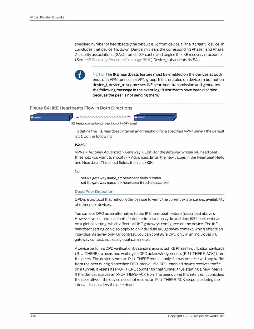
specified number of heartbeats (the default is 5) from device_t (the “target”), device_m
concludes that device_t is down. Device_m clears the corresponding Phase 1 and Phase
2 security associations (SAs) from its SA cache and begins the IKE recovery procedure.
(See “IKE Recovery Procedure” on page 306.) Device_t also clears its SAs.
NOTE: The IKE heartbeats featuremust be enabled on the devices at bothends of a VPN tunnel in a VPN group. If it is enabled on device_m but not ondevice_t, device_m suppresses IKE heartbeat transmission and generatesthe followingmessage in the event log: “Heartbeats have been disabledbecause the peer is not sending them.”
Figure 84: IKE Heartbeats Flow in Both Directions
To define the IKE heartbeat interval and threshold for a specified VPN tunnel (the default
is 5), do the following:
WebUI
VPNs > AutoKey Advanced > Gateway > Edit (for the gateway whose IKE heartbeat
threshold you want to modify) > Advanced: Enter the new values in the Heartbeat Hello
and Heartbeat Threshold fields, then click OK.
CLI
set ike gateway name_str heartbeat hello numberset ike gateway name_str heartbeat threshold number
Dead Peer Detection
DPD is a protocol that network devices use to verify the current existence and availability
of other peer devices.
You can use DPD as an alternative to the IKE heartbeat feature (described above).
However, you cannot use both features simultaneously. In addition, IKE heartbeat can
be a global setting, which affects all IKE gateways configured on the device. The IKE
heartbeat setting can also apply to an individual IKE gateway context, which affects an
individual gateway only. By contrast, you can configure DPD only in an individual IKE
gateway context, not as a global parameter.
A device performs DPD verification by sending encrypted IKE Phase 1 notification payloads
(R-U-THERE) to peers and waiting for DPD acknowledgements (R-U-THERE-ACK) from
the peers. The device sends an R-U-THERE request only if it has not received any traffic
from the peer during a specified DPD interval. If a DPD-enabled device receives traffic
on a tunnel, it resets its R-U-THERE counter for that tunnel, thus starting a new interval.
If the device receives an R-U-THERE-ACK from the peer during this interval, it considers
the peer alive. If the device does not receive an R-U-THERE-ACK response during the
interval, it considers the peer dead.
Copyright © 2012, Juniper Networks, Inc.304
Virtual Private Networks

When the device changes the status of a peer device to be dead, the device removes the
Phase 1 SA and all Phase 2 SAs for that peer. In previous ScreenOS releases, the failed
VPN tunnel could not fail over to another tunnel and gateway in the group. To maintain
continuous connectivity even if a peer goes dead, in the current ScreenOS release the
dead peer fails over the tunnel to another group member with the second highest weight.
Meanwhile, the device attempts to renegotiate the tunnel with the peer identified as
dead. Once the tunnel is successfully negotiated, the tunnel automatically fails back to
the first member. The weighting system always causes the best ranked gateway in the
group to handle the VPN data whenever possible.
You can configure the following DPD parameters, either through the CLI or the WebUI:
• The interval parameter specifies the DPD interval. This interval is the amount of time
(expressed in seconds) the device allows to pass before considering a peer to be dead.
• The always-send parameter instructs the device to send DPD requests regardless of
whether there is IPsec traffic with the peer.
• The retry parameter specifies the maximum number of times to send the R-U-THERE
request before considering the peer to be dead. As with an IKE heartbeat configuration,
the default number of transmissions is 5 times, with a permissible range of 1-128 retries.
A setting of zero disables DPD.
• The reconnectparameter instructs the device to renegotiate the tunnel at the specified
interval with the peer considered to be dead. As with an IKE recovery configuration,
the minimum setting is 60 seconds. You can set the interval at any value between 60
and 9999 seconds.
In the following example you create a gateway that uses a DPD interval of five seconds.
WebUI
VPNs > AutoKey Advanced > Gateway > Edit: Create a gateway by entering the following
values, then clicking OK.
Gateway Name: our_gatewaySecurity Level: StandardRemote Gateway Type: Static IP AddressIP Address/Hostname: 1.1.1.1
Preshared Key: jun9345
VPNs > AutoKey Advanced > Gateway > Edit (our_gateway): Enter the following values,
then click OK.
Predefined: Standard (select)DPD:Interval: 5
CLI
set ike gateway "our_gateway" address 1.1.1.1main outgoing-interface "untrust" preshare"jun9345" sec-level standardset ike gateway "our_gateway" dpd interval 5
305Copyright © 2012, Juniper Networks, Inc.
Chapter 7: Advanced Virtual Private Network Features

IKE Recovery Procedure
After the monitoring security device determines that a targeted device is down, the
monitor stops sending IKE heartbeats and clears the SAs for that peer from its SA cache.
After a defined interval, the monitor attempts to initiate Phase 1 negotiations with the
failed peer. If the first attempt is unsuccessful, the monitor continues to attempt Phase
1 negotiations at regular intervals until negotiations are successful.
Figure 85: Repeated IKE Phase 1 Negotiation Attempts
To define the IKE recovery interval for a specified VPN tunnel (the minimum setting is
60 seconds), do either of the following:
WebUI
VPNs > AutoKey Advanced > Gateway > Edit (for the gateway whose IKE reconnect
interval you want to modify) > Advanced: Enter the value in seconds in the Heartbeat
Reconnect field, then click OK.
CLI
set ike gateway name_str heartbeat reconnect number
When a VPN group member with the highest weight fails over the tunnel to another group
member and then reconnects with the monitoring device, the tunnel automatically fails
back to the first member. The weighting system always causes the best ranking gateway
in the group to handle the VPN data whenever it can do so.
Figure 86 on page 307 presents the process that a member of a VPN group undergoes
when the missing heartbeats from a targeted gateway surpass the failure threshold.
Copyright © 2012, Juniper Networks, Inc.306
Virtual Private Networks

Figure 86: Failover and Then Recovery
Monitor Target
IKE heartbeats flowing in both directions
Target stops sending IKE heartbeats.
Monitor fails over the VPN (if target was handling VPN data), clears the P1 andP2 SAs, and attempts to reestablish the VPN tunnel at specified intervals.
Target responds to P1 initiation with IKE heartbeats enabled.
IKE P1 and P2 negotiations succeed, tunnel is back up, and VPNfails back (if its weight preempts other VPN group members).
TCP SYN-Flag Checking
For a seamless VPN failover to occur, the handling of TCP sessions must be addressed.
If, after a failover, the new active gateway receives a packet in an existing TCP session,
the new gateway treats it as the first packet in a new TCP session and checks if the SYN
flag is set in the packet header. Because this packet is really part of an existing session,
it does not have the SYN flag set. Consequently, the new gateway rejects the packet.
With TCP SYN flag checking enabled, all TCP applications have to reconnect after the
failover occurs.
To resolve this, you can disable SYN-flag checking for TCP sessions in VPN tunnels, as
follows:
WebUI
You cannot disable SYN-flag checking through the WebUI.
CLI
unset flow tcp-syn-check-in-tunnel
NOTE: By default, SYN-flag checking is enabled.
307Copyright © 2012, Juniper Networks, Inc.
Chapter 7: Advanced Virtual Private Network Features

Creating Redundant VPN Gateways
In this example, a corporate site has one VPN tunnel to a data center and a second tunnel
to a backup data center. All the data is mirrored through a leased line connection between
the two data center sites. The data centers are physically separate to provide continuous
service even in the event of a catastrophic failure such as an all-day power outage or a
natural disaster.
The device location and name, the physical interfaces and their IP addresses for the Trust
and Untrust zones, and the VPN group ID and weight for each security device are as
follows:
VPNGroupID andWeight
Physical Interface, IP Address,Default Gateway (Untrust Zone)
Physical Interfaceand IP Address(Trust Zone)
DeviceNameDevice Location
– –ethernet3, 1.1.1.1/24, (GW) 1.1.1.2ethernet1, 10.10.1.1/24Monitor1Corporate
ID = 1, Weight = 2ethernet3, 2.2.2.1/24, (GW) 2.2.2.2ethernet1, 10.1.1.1/16Target1Data Center (Primary)
ID = 1, Weight =1ethernet3, 3.3.3.1/24, (GW) 3.3.3.2ethernet1, 10.1.1.1/16Target2Data Center (Backup)
NOTE: The internaladdressspaceatbothdatacenter sitesmustbe identical.
All security zones are in the trust-vr routing domain. All the Site-to-Site AutoKey IKE
tunnels use the security level predefined as “Compatible” for both Phase 1 and Phase 2
proposals. Preshared keys authenticate the participants.
Figure 87: Redundant VPNGateways
WebUI (Monitor1)
1. Interfaces
Network > Interfaces > Edit (for ethernet1): Enter the following, then click Apply:
Copyright © 2012, Juniper Networks, Inc.308
Virtual Private Networks

Zone Name: TrustStatic IP: (select this option when present)IP Address/Netmask: 10.10.1.1/24Enter the following, then clickOK:Interface Mode: NAT
Network > Interfaces > Edit (for ethernet3): Enter the following, then click OK:
Zone Name: UntrustStatic IP: (select this option when present)IP Address/Netmask: 1.1.1.1/24
2. Addresses
Policy > Policy Elements > Addresses > List > New: Enter the following, then clickOK:
Address Name: in_trustIP Address/Domain Name:IP/Netmask: (select), 10.10.1.0/24
Zone: Trust
Policy > Policy Elements > Addresses > List > New: Enter the following, then clickOK:
Address Name: data_ctrIP Address/Domain Name:IP/Netmask: (select), 10.1.0.0/16
Zone: Untrust
3. VPNs
VPNs > AutoKey Advanced > VPN Group: Enter 1 in the VPN Group ID field, then click
Add.
VPNs > AutoKey Advanced > Gateway > New: Enter the following, then click OK:
Gateway Name: target1Security Level: CompatibleRemote Gateway Type: Static IP Address: (select), IP Address: 2.2.2.1Preshared Key: SLi1yoo129Outgoing Interface: ethernet3
> Advanced: Enter the following advanced settings, then click Return to return to the
basic Gateway configuration page:
Security Level: CompatibleMode (Initiator): Main (ID Protection)Heartbeat:Hello: 3 SecondsReconnect: 60 secondsThreshold: 5
VPNs > AutoKey IKE > New: Enter the following, then click OK:
VPNName: to_target1Security Level: CompatibleRemote Gateway: Predefined: (select), target1
> Advanced: Enter the following advanced settings, then click Return to return to the
basic AutoKey IKE configuration page:
VPNGroup: VPN Group-1Weight: 2
309Copyright © 2012, Juniper Networks, Inc.
Chapter 7: Advanced Virtual Private Network Features

VPNs > AutoKey Advanced > Gateway > New: Enter the following, then click OK:
Gateway Name: target2Security Level: CompatibleRemote Gateway Type: Static IP Address: (select), IP Address: 3.3.3.1Preshared Key: CMFwb7oN23Outgoing Interface: ethernet3
> Advanced: Enter the following advanced settings, then click Return to return to the
basic Gateway configuration page:
Security Level: CompatibleMode (Initiator): Main (ID Protection)Heartbeat:Hello: 3 SecondsReconnect: 60 secondsThreshold: 5
VPNs > AutoKey IKE > New: Enter the following, then click OK:
VPNName: to_target2Security Level: CompatibleRemote Gateway: Predefined: (select), target2
> Advanced: Enter the following advanced settings, then click Return to return to the
basic AutoKey IKE configuration page:
VPNGroup: VPN Group-1Weight: 1
4. Route
Network > Routing > Routing Entries > trust-vr New: Enter the following, then click
OK:
Network Address / Netmask: 0.0.0.0/0Gateway: (select)Interface: ethernet3Gateway IP Address: 1.1.1.2(untrust)
5. Policies
Policies > (From: Trust, To: Untrust) New: Enter the following, then click OK:
Source Address:Address Book Entry: (select), in_trust
Destination Address:Address Book Entry: (select), data_ctr
Service: ANYAction: TunnelVPN: VPN Group-1Modify matching bidirectional VPN policy: (select)Position at Top: (select)
WebUI (Target1)
1. Interfaces
Network > Interfaces > Edit (for ethernet1): Enter the following, then click Apply:
Copyright © 2012, Juniper Networks, Inc.310
Virtual Private Networks

Zone Name: TrustStatic IP: (select this option when present)IP Address/Netmask: 10.1.1.1/16Enter the following, then clickOK:Interface Mode: NAT
Network > Interfaces > Edit (for ethernet3): Enter the following, then click OK:
Zone Name: UntrustStatic IP: (select this option when present)IP Address/Netmask: 2.2.2.1/24
2. Addresses
Policy > Policy Elements > Addresses > List > New: Enter the following, then clickOK:
Address Name: in_trustIP Address/Domain Name:IP/Netmask: (select), 10.1.0.0/16
Zone: Trust
Policy > Policy Elements > Addresses > List > New: Enter the following, then clickOK:
Address Name: corpIP Address/Domain Name:IP/Netmask: (select), 10.10.1.0/24
Zone: Untrust
3. VPN
VPNs > AutoKey Advanced > Gateway > New: Enter the following, then click OK:
Gateway Name: monitor1Security Level: CompatibleRemote Gateway Type:Static IP Address: (select), IP Address/Hostname: 1.1.1.1
Preshared Key: SLi1yoo129Outgoing Interface: ethernet3
> Advanced: Enter the following advanced settings, then click Return to return to the
basic Gateway configuration page:
Security Level: CompatibleMode (Initiator): Main (ID Protection)Heartbeat:Hello: 3 SecondsReconnect: 0 seconds
VPNs > AutoKey IKE > New: Enter the following, then click OK:
Name: to_monitor1Security Level: CompatibleRemote Gateway: Predefined: (select), monitor1
4. Route
Network > Routing > Routing Entries > trust-vr New: Enter the following, then click
OK:
Network Address / Netmask: 0.0.0.0/0Gateway: (select)
311Copyright © 2012, Juniper Networks, Inc.
Chapter 7: Advanced Virtual Private Network Features

Interface: ethernet3Gateway IP Address: 2.2.2.2
5. Policies
Policies > ( From: Trust, To: Untrust) New: Enter the following, then click OK:
Source Address:Address Book Entry: (select), in_trust
Destination Address:Address Book Entry: (select), corp
Service: ANYAction: TunnelTunnel VPN: monitor1Modify matching bidirectional VPN policy: (select)Position at Top: (select)
WebUI (Target2)
NOTE: FollowtheTarget1 configurationsteps toconfigureTarget2, butdefinethe Untrust zone interface IP address as 3.3.3.1/24, the default gateway IPaddress as 3.3.3.2, and use CMFwb7oN23 to generate the preshared key.
CLI (Monitor1)
1. Interfaces
set interface ethernet1 zone trustset interface ethernet1 ip 10.10.1.1/24set interface ethernet1 natset interface ethernet3 zone untrustset interface ethernet3 ip 1.1.1.1/24
2. Addresses
set address trust in_trust 10.10.1.0/24set address untrust data_ctr 10.1.0.0/16
3. VPNs
set ike gateway target1 address 2.2.2.1 main outgoing-interface ethernet3 preshareSLi1yoo129 sec-level compatibleset ike gateway target1 heartbeat hello 3set ike gateway target1 heartbeat reconnect 60set ike gateway target1 heartbeat threshold 5set vpn to_target1 gateway target1 sec-level compatibleset ike gateway target2 address 3.3.3.1 main outgoing-interface ethernet3 preshareCMFwb7oN23 sec-level compatibleset ike gateway target2 heartbeat hello 3set ike gateway target2 heartbeat reconnect 60set ike gateway target2 heartbeat threshold 5set vpn to_target2 gateway target2 sec-level compatibleset vpn-group id 1 vpn to_target1 weight 2set vpn-group id 1 vpn to_target2 weight 1unset flow tcp-syn-check-in-tunnel
Copyright © 2012, Juniper Networks, Inc.312
Virtual Private Networks

4. Route
set vrouter trust-vr route 0.0.0.0/0 interface ethernet3 gateway 1.1.1.2
5. Policies
set policy top from trust to untrust in_trust data_ctr any tunnel “vpn-group 1”set policy top from untrust to trust data_ctr in_trust any tunnel “vpn-group 1”save
CLI (Target1)
1. Interfaces
set interface ethernet1 zone trustset interface ethernet1 ip 10.1.1.1/16set interface ethernet1 natset interface ethernet3 zone untrustset interface ethernet3 ip 2.2.2.1/24
2. Addresses
set address trust in_trust 10.1.0.0/16set address untrust corp 10.10.1.0/24
3. VPN
set ike gatewaymonitor1 address 1.1.1.1 main outgoing-interface ethernet3 preshareSLi1yoo129 sec-level compatibleset ike gatewaymonitor1 heartbeat hello 3set ike gatewaymonitor1 heartbeat threshold 5set vpn to_monitor1 gatewaymonitor1 sec-level compatible
4. Route
set vrouter trust-vr route 0.0.0.0/0 interface ethernet3 gateway 2.2.2.2
5. Policies
set policy top from trust to untrust in_trust corp any tunnel vpn to_monitorset policy top from untrust to trust corp in_trust any tunnel vpn to_monitorsave
CLI (Target2)
NOTE: FollowtheTarget1 configurationsteps toconfigureTarget2, butdefinethe Untrust zone interface IP address as 3.3.3.1/24, the default gateway IPaddress as 3.3.3.2, and use CMFwb7oN23 to generate the preshared key.
Creating Back-to-Back VPNs
You can enforce interzone policies at the hub site for traffic passing from one VPN tunnel
to another by putting the spoke sites in different zones. Because they are in different
zones, the security device at the hub must do a policy lookup before routing the traffic
from one tunnel to another. You can control the traffic flowing through the VPN tunnels
between the spoke sites. This arrangement is called back-to-back VPNs.
313Copyright © 2012, Juniper Networks, Inc.
Chapter 7: Advanced Virtual Private Network Features

NOTE: Optionally, youcanenable intrazoneblockinganddefinean intrazonepolicy to control traffic between the two tunnel interfaces within the samezone.
Figure 88: Back-to-Back VPNs
Hub
Spoke A Spoke B
PolicyLookup
VPN2VPN1
X1Zone X2
Zone
Following are a few benefits of back-to-back VPNs:
• You can conserve the number of VPNs you need to create. For example, perimeter site
A can link to the hub and to perimeter sites B, C, D…, but A only has to set up one VPN
tunnel. Especially for NetScreen-5XP users, who can use a maximum of ten VPN tunnels
concurrently, applying the hub-and-spoke method dramatically increases their VPN
options and capabilities.
• The administrator (admin) at the hub device can completely control VPN traffic
between perimeter sites. For example,
• The admin might permit only HTTP traffic to flow from sites A to B, but allow any
kind of traffic to flow from B to A.
• The admin can allow traffic originating from A to reach C, but deny traffic originating
from C to reach A.
• The admin can allow a specific host at A to reach the entire D network, while allowing
only a specific host at D to reach a different host at A.
• The administrator at the hub device can completely control outbound traffic from all
perimeter networks. At each perimeter site, there must first be a policy that tunnels all
outbound traffic through the spoke VPNs to the hub; for example: set policy top fromtrust tountrustanyanyanytunnelvpnname_str (where name_str defines the specific
VPN tunnel from each perimeter site to the hub). At the hub, the administrator can
control Internet access, allowing certain kinds of traffic (such as HTTP only), performing
URL blocking on undesirable websites, and so on.
• Regional hubs can be used and interconnected through spoke tunnels, allowing spoke
sites in one region to reach spoke sites in another.
Copyright © 2012, Juniper Networks, Inc.314
Virtual Private Networks
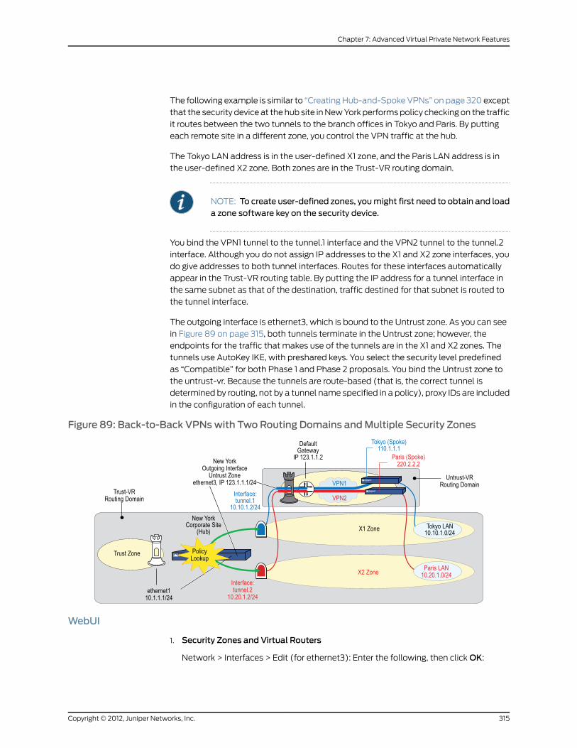
The following example is similar to “Creating Hub-and-Spoke VPNs” on page 320 except
that the security device at the hub site in New York performs policy checking on the traffic
it routes between the two tunnels to the branch offices in Tokyo and Paris. By putting
each remote site in a different zone, you control the VPN traffic at the hub.
The Tokyo LAN address is in the user-defined X1 zone, and the Paris LAN address is in
the user-defined X2 zone. Both zones are in the Trust-VR routing domain.
NOTE: To create user-defined zones, youmight first need to obtain and loada zone software key on the security device.
You bind the VPN1 tunnel to the tunnel.1 interface and the VPN2 tunnel to the tunnel.2
interface. Although you do not assign IP addresses to the X1 and X2 zone interfaces, you
do give addresses to both tunnel interfaces. Routes for these interfaces automatically
appear in the Trust-VR routing table. By putting the IP address for a tunnel interface in
the same subnet as that of the destination, traffic destined for that subnet is routed to
the tunnel interface.
The outgoing interface is ethernet3, which is bound to the Untrust zone. As you can see
in Figure 89 on page 315, both tunnels terminate in the Untrust zone; however, the
endpoints for the traffic that makes use of the tunnels are in the X1 and X2 zones. The
tunnels use AutoKey IKE, with preshared keys. You select the security level predefined
as “Compatible” for both Phase 1 and Phase 2 proposals. You bind the Untrust zone to
the untrust-vr. Because the tunnels are route-based (that is, the correct tunnel is
determined by routing, not by a tunnel name specified in a policy), proxy IDs are included
in the configuration of each tunnel.
Figure 89: Back-to-Back VPNswith Two Routing Domains andMultiple Security Zones
WebUI
1. Security Zones and Virtual Routers
Network > Interfaces > Edit (for ethernet3): Enter the following, then click OK:
315Copyright © 2012, Juniper Networks, Inc.
Chapter 7: Advanced Virtual Private Network Features

IP Address/Netmask: 0.0.0.0/0Manage IP: 0.0.0.0
Network > Interfaces > Edit (for ethernet3): Enter the following, then click OK:
Zone Name: Null
Network > Zones > Edit (for Untrust): Enter the following, then click OK:
Virtual Router Name: untrust-vrBlock Intra-Zone Traffic: (select)
Network > Zones > New: Enter the following, then click OK:
Zone Name: X1Virtual Router Name: trust-vrBlock Intra-Zone Traffic: (select)
Network > Zones > New: Enter the following, then click OK:
Name: X2Virtual Router Name: trust-vrBlock Intra-Zone Traffic: (select)
2. Interfaces
Network > Interfaces > Edit (for ethernet3): Enter the following, then click OK:
Zone Name: UntrustStatic IP: (select this option when present)IP Address/Netmask: 123.1.1.1/24
Network > Interfaces > New Tunnel IF: Enter the following, then click OK:
Tunnel Interface Name: tunnel.1Zone (VR): X1 (trust-vr)Fixed IP: (select)IP Address / Netmask: 10.10.1.2/24
Network > Interfaces > New Tunnel IF: Enter the following, then click OK:
Tunnel Interface Name: tunnel.2Zone (VR): X2 (trust-vr)Fixed IP: (select)IP Address / Netmask: 10.20.1.2/24
3. VPN for Tokyo Office
VPNs > AutoKey IKE > New: Enter the following, then click OK:
VPNName: VPN1Security Level: CompatibleRemote Gateway: Create a Simple Gateway: (select)Gateway Name: TokyoType: Static IP: (select), Address/Hostname: 110.1.1.1Preshared Key: netscreen1Outgoing Interface: ethernet3
> Advanced: Enter the following advanced settings, then click Return to return to the
basic AutoKey IKE configuration page:
Proxy-ID: (select)Local IP / Netmask: 10.20.1.0/24
Copyright © 2012, Juniper Networks, Inc.316
Virtual Private Networks
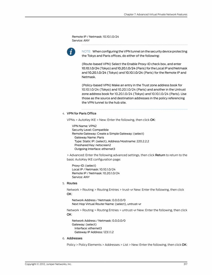
Remote IP / Netmask: 10.10.1.0/24Service: ANY
NOTE: Whenconfiguring theVPNtunnelon thesecuritydeviceprotectingthe Tokyo and Paris offices, do either of the following:
(Route-based VPN) Select the Enable Proxy-ID check box, and enter10.10.1.0/24 (Tokyo)and 10.20.1.0/24 (Paris) for theLocal IPandNetmaskand 10.20.1.0/24 (Tokyo) and 10.10.1.0/24 (Paris) for the Remote IP andNetmask.
(Policy-based VPN)Make an entry in the Trust zone address book for10.10.1.0/24 (Tokyo) and 10.20.1.0/24 (Paris) and another in the Untrustzone address book for 10.20.1.0/24 (Tokyo) and 10.10.1.0/24 (Paris). Usethose as the source and destination addresses in the policy referencingthe VPN tunnel to the hub site.
4. VPN for Paris Office
VPNs > AutoKey IKE > New: Enter the following, then click OK:
VPNName: VPN2Security Level: CompatibleRemote Gateway: Create a Simple Gateway: (select)Gateway Name: ParisType: Static IP: (select), Address/Hostname: 220.2.2.2Preshared Key: netscreen2Outgoing Interface: ethernet3
> Advanced: Enter the following advanced settings, then click Return to return to the
basic AutoKey IKE configuration page:
Proxy-ID: (select)Local IP / Netmask: 10.10.1.0/24Remote IP / Netmask: 10.20.1.0/24Service: ANY
5. Routes
Network > Routing > Routing Entries > trust-vr New: Enter the following, then click
OK:
Network Address / Netmask: 0.0.0.0/0Next Hop Virtual Router Name: (select), untrust-vr
Network > Routing > Routing Entries > untrust-vr New: Enter the following, then click
OK:
Network Address / Netmask: 0.0.0.0/0Gateway: (select)Interface: ethernet3Gateway IP Address: 123.1.1.2
6. Addresses
Policy > Policy Elements > Addresses > List > New: Enter the following, then clickOK:
317Copyright © 2012, Juniper Networks, Inc.
Chapter 7: Advanced Virtual Private Network Features

Address Name: Tokyo LANIP Address/Domain Name:IP/Netmask: (select), 10.10.1.0/24
Zone: X1
Policy > Policy Elements > Addresses > List > New: Enter the following, then clickOK:
Address Name: Paris LANIP Address/Domain Name:IP/Netmask: (select), 10.20.1.0/24
Zone: X2
7. Policies
Policy > (From: X1, To: X2) New: Enter the following, then click OK:
Source Address:Address Book Entry: (select), Tokyo LAN
Destination Address:Address Book Entry: (select), Paris LAN
Service: ANYAction: PermitPosition at Top: (select)
Policy > (From: X2, To: X1) New: Enter the following, then click OK:
Source Address:Address Book Entry: (select), Paris LAN
Destination Address:Address Book Entry: (select), Tokyo LAN
Service: ANYAction: PermitPosition at Top: (select)
CLI
1. Security Zones and Virtual Routers
unset interface ethernet3 ipunset interface ethernet3 zoneset zone untrust vrouter untrust-vrset zone untrust blockset zone name X1set zone x1 vrouter trust-vrset zone x1 blockset zone name x2set zone x2 vrouter trust-vrset zone x2 block
2. Interfaces
set interface ethernet3 zone untrustset interface ethernet3 ip 123.1.1.1/24set interface tunnel.1 zone x1set interface tunnel.1 ip 10.10.1.2/24set interface tunnel.2 zone x2set interface tunnel.2 ip 10.20.1.2/24
3. VPN for Tokyo Office
Copyright © 2012, Juniper Networks, Inc.318
Virtual Private Networks

set ike gateway Tokyo address 110.1.1.1 outgoing-interface ethernet3 presharenetscreen1 sec-level compatibleset vpn VPN1 gateway Tokyo sec-level compatibleset vpn VPN1 bind interface tunnel.1set vpn VPN1 proxy-id local-ip 10.20.1.0/24 remote-ip 10.10.1.0/24 any
NOTE: Whenconfiguring theVPNtunnelon thesecuritydeviceprotectingthe Tokyo and Paris offices, do either of the following:
(Route-basedVPN)Enter the followingcommands:setvpnVPN1proxy-idlocal-ip 10.20.1.0/24 remote-ip 10.10.1.0/24 (Tokyo) and set vpn VPN1proxy-id local-ip 10.10.1.0/24 remote-ip 10.20.1.0/24 (Paris).
(Policy-based VPN)Make an entry in the Trust zone address book for10.10.1.0/24 (Tokyo) and 10.20.1.0/24 (Paris) and another in the Untrustzone address book for 10.20.1.0/24 (Tokyo) and 10.10.1.0/24 (Paris). Usethose as the source and destination addresses in the policies referencingthe VPN tunnel to the hub site.
4. VPN for Paris Office
set ike gateway Paris address 220.2.2.2 outgoing-interface ethernet3 presharenetscreen2 sec-level compatibleset vpn VPN2 gateway Paris sec-level compatibleset vpn VPN2 bind interface tunnel.2set vpn VPN2 proxy-id local-ip 10.10.1.0/24 remote-ip 10.20.1.0/24 any
5. Routes
set vrouter trust-vr route 0.0.0.0/0 vrouter untrust-vrset vrouter untrust-vr route 0.0.0.0/0 interface ethernet3 gateway 123.1.1.2
6. Addresses
set address x1 “Tokyo LAN” 10.10.1.0/24set address x2 “Paris LAN” 10.20.1.0/24
7. Policies
set policy top from x1 to x2 “Tokyo LAN” “Paris LAN” any permitset policy top from x2 to x1 “Paris LAN” “Tokyo LAN” any permitsave
NOTE: You can ignore the followingmessage, which appears becausetunnel interfaces are in NATmode:
Warning: Some interfaces in the zone_name zone are in NATmode. Trafficmight not pass through them!
319Copyright © 2012, Juniper Networks, Inc.
Chapter 7: Advanced Virtual Private Network Features

Creating Hub-and-Spoke VPNs
If you create two VPN tunnels that terminate at a security device, you can set up a pair
of routes so that the security device directs traffic exiting one tunnel to the other tunnel.
If both tunnels are contained within a single zone, you do not need to create a policy to
permit the traffic to pass from one tunnel to the other. You only need to define the routes.
Such an arrangement is known as a hub-and-spoke VPN.
You can also configure multiple VPNs in one zone and route traffic between any two
tunnels.
Figure 90: Multiple Tunnels in a Hub-and-Spoke VPN Configuration
Untrust Zone
The security device routes traffic between tunnels.
Multiple Hub-and-Spoke VPN Tunnels
In this example, two branch offices in Tokyo and Paris communicate with each other
through a pair of VPN tunnels—VPN1 and VPN2. Each tunnel originates at the remote
site and terminates at the corporate site in New York. The security device at the corporate
site routes traffic exiting one tunnel into the other tunnel.
By disabling intrazone blocking, the security device at the corporate site only needs to
do a route lookup—not a policy lookup—when conducting traffic from tunnel to tunnel
because both remote endpoints are in the same zone (the Untrust Zone).
NOTE: Optionally, you can leave intrazone blocking enabled and define anintrazone policy permitting traffic between the two tunnel interfaces.
You bind the tunnels to the tunnel interfaces—tunnel.1 and tunnel.2—which are both
unnumbered. The tunnels use AutoKey IKE, with the preshared keys. You select the
security level predefined as “Compatible” for both Phase 1 and Phase 2 proposals. You
bind the Untrust zone to the untrust-vr. The Untrust zone interface is ethernet3.
NOTE: The following configuration is for route-based VPNs. If you configurepolicy-basedhub-and-spokeVPNs, youmustuse theTrustandUntrust zonesin the policies; you cannot use user-defined security zones.
Copyright © 2012, Juniper Networks, Inc.320
Virtual Private Networks

Figure 91: Hub-and-Spoke VPNs
WebUI (New York)
1. Security Zones and Virtual Routers
Network > Interfaces > Edit (for ethernet3): Enter the following, then click OK:
IP Address/Netmask: 0.0.0.0/0Manage IP: 0.0.0.0
Network > Interfaces > Edit (for ethernet3): Enter the following, then click OK:
Zone Name: Null
Network > Zones > Edit (for Untrust): Enter the following, then click OK:
Virtual Router Name: untrust-vrBlock Intra-Zone Traffic: (clear)
2. Interfaces
Network > Interfaces > Edit (for ethernet3): Enter the following, then click OK:
Zone Name: UntrustStatic IP: (select this option when present)IP Address/Netmask: 1.1.1.1/24
Network > Interfaces > New Tunnel IF: Enter the following, then click OK:
Tunnel Interface Name: tunnel.1Zone (VR): Untrust (untrust-vr)Unnumbered: (select)Interface: ethernet3 (untrust-vr)
Network > Interfaces > New Tunnel IF: Enter the following, then click OK:
Tunnel Interface Name: tunnel.2Zone (VR): Untrust (untrust-vr)Unnumbered: (select)Interface: ethernet3 (untrust-vr)
3. VPN for Tokyo Office
VPNs > AutoKey IKE > New: Enter the following, then click OK:
321Copyright © 2012, Juniper Networks, Inc.
Chapter 7: Advanced Virtual Private Network Features

VPNName: VPN1Security Level: CompatibleRemote Gateway: Create a Simple Gateway: (select)Gateway Name: TokyoType: Static IP: (select), Address/Hostname: 2.2.2.2Preshared Key: netscreen1Security Level: CompatibleOutgoing Interface: ethernet3
> Advanced: Enter the following advanced settings, then click Return to return to the
basic AutoKey IKE configuration page:
Proxy-ID: (select)Local IP / Netmask: 0.0.0.0/0Remote IP / Netmask: 0.0.0.0/0Service: ANY
4. VPN for Paris Office
VPNs > AutoKey IKE > New: Enter the following, then click OK:
VPNName: VPN2Security Level: CompatibleRemote Gateway: Create a Simple Gateway: (select)Gateway Name: ParisType: Static IP: (select), Address/Hostname: 3.3.3.3Preshared Key: netscreen2Security Level: CompatibleOutgoing Interface: ethernet3
> Advanced: Enter the following advanced settings, then click Return to return to the
basic AutoKey IKE configuration page:
Proxy-ID: (select)Local IP / Netmask: 0.0.0.0/0Remote IP / Netmask: 0.0.0.0/0Service: ANY
5. Routes
Network > Routing > Routing Entries > untrust-vr New: Enter the following, then click
OK:
Network Address / Netmask: 10.2.2.0/24Gateway: (select)Interface: tunnel.1Gateway IP Address: 0.0.0.0
Network > Routing > Routing Entries > untrust-vr New: Enter the following, then click
OK:
Network Address / Netmask: 10.3.3.0/24Gateway: (select)Interface: tunnel.2Gateway IP Address: 0.0.0.0
Network > Routing > Routing Entries > untrust-vr New: Enter the following, then click
OK:
Copyright © 2012, Juniper Networks, Inc.322
Virtual Private Networks

Network Address / Netmask: 0.0.0.0/0Gateway: (select)Interface: ethernet3Gateway IP Address: 1.1.1.250
WebUI (Tokyo)
1. Security Zones and Virtual Routers
Network > Interfaces > Edit (for ethernet3): Enter the following, then click OK:
IP Address/Netmask: 0.0.0.0/0Manage IP: 0.0.0.0
Network > Interfaces > Edit (for ethernet3): Enter the following, then click OK:
Zone Name: Null
Network > Zones > Edit (for Untrust): Enter the following, then click OK:
Virtual Router Name: untrust-vrBlock Intra-Zone Traffic: (select)
2. Interfaces
Network > Interfaces > Edit (for ethernet1): Enter the following, then click Apply:
Zone Name: TrustStatic IP: (select this option when present)IP Address/Netmask: 10.2.2.1/24Select the following, then clickOK:Interface Mode: NAT
Network > Interfaces > Edit (for ethernet3): Enter the following, then click OK:
Zone Name: UntrustStatic IP: (select this option when present)IP Address/Netmask: 2.2.2.2/24
Network > Interfaces > New Tunnel IF: Enter the following, then click OK:
Tunnel Interface Name: tunnel.1Zone (VR): Untrust (untrust-vr)Unnumbered: (select)Interface: ethernet3 (untrust-vr)
3. Address
Policy > Policy Elements > Addresses > List > New: Enter the following, then clickOK:
Address Name: ParisIP Address/Domain Name:IP/Netmask: (select), 10.3.3.0/24
Zone: Untrust
4. VPN
VPNs > AutoKey IKE > New: Enter the following, then click OK:
VPNName: VPN1Security Level: CompatibleRemote Gateway: Create a Simple Gateway: (select)
323Copyright © 2012, Juniper Networks, Inc.
Chapter 7: Advanced Virtual Private Network Features

Gateway Name: New YorkType: Static IP: (select), Address/Hostname: 1.1.1.1Preshared Key: netscreen1Security Level: CompatibleOutgoing Interface: ethernet3
> Advanced: Enter the following advanced settings, then click Return to return to the
basic AutoKey IKE configuration page:
Proxy-ID: (select)Local IP / Netmask: 0.0.0.0/0Remote IP / Netmask: 0.0.0.0/0Service: ANY
5. Routes
Network > Routing > Routing Entries > trust-vr New: Enter the following, then click
OK:
Network Address / Netmask: 0.0.0.0/0Next Hop Virtual Router Name: (select); untrust-vr
Network > Routing > Routing Entries > untrust-vr New: Enter the following, then click
OK:
Network Address / Netmask: 0.0.0.0/0Gateway: (select)Interface: ethernet3Gateway IP Address: 2.2.2.250
Network > Routing > Routing Entries > untrust-vr New: Enter the following, then click
OK:
Network Address / Netmask: 10.3.3.0/24Gateway: (select)Interface: tunnel.1Gateway IP Address: 0.0.0.0
6. Policies
Policies > (From: Trust, To: Untrust) New: Enter the following, then click OK:
Source Address:Address Book Entry: (select), Any
Destination Address:Address Book Entry: (select), Paris
Service: ANYAction: Permit
WebUI (Paris)
1. Security Zones and Virtual Routers
Network > Interfaces > Edit (for ethernet3): Enter the following, then click OK:
IP Address/Netmask: 0.0.0.0/0Manage IP: 0.0.0.0
Network > Interfaces > Edit (for ethernet3): Enter the following, then click OK:
Zone Name: Null
Copyright © 2012, Juniper Networks, Inc.324
Virtual Private Networks

Network > Zones > Edit (for Untrust): Enter the following, then click OK:
Virtual Router Name: untrust-vrBlock Intra-Zone Traffic: (select)
2. Interfaces
Network > Interfaces > Edit (for ethernet1): Enter the following, then click Apply:
Zone Name: TrustStatic IP: (select this option when present)IP Address/Netmask: 10.3.3.1/24Select the following, then clickOK:Interface Mode: NAT
Network > Interfaces > Edit (for ethernet3): Enter the following, then click OK:
Zone Name: UntrustStatic IP: (select this option when present)IP Address/Netmask: 3.3.3.3/24
Network > Interfaces > New Tunnel IF: Enter the following, then click OK:
Tunnel Interface Name: tunnel.1Zone (VR): Untrust (untrust-vr)Unnumbered: (select)Interface: ethernet3 (untrust-vr)
3. Address
Policy > Policy Elements > Addresses > List > New: Enter the following, then clickOK:
Address Name: TokyoIP Address/Domain Name:IP/Netmask: (select), 10.2.2.0/24
Zone: Untrust
4. VPN
VPNs > AutoKey IKE > New: Enter the following, then click OK:
VPNName: VPN2Security Level: CompatibleRemote Gateway: Create a Simple Gateway: (select)Gateway Name: New YorkType: Static IP: (select), Address/Hostname: 1.1.1.1Preshared Key: netscreen2Security Level: CompatibleOutgoing Interface: ethernet3
> Advanced: Enter the following advanced settings, then click Return to return to the
basic AutoKey IKE configuration page:
Proxy-ID: (select)Local IP / Netmask: 0.0.0.0/0Remote IP / Netmask: 0.0.0.0/0Service: ANY
5. Routes
Network > Routing > Routing Entries > trust-vr New: Enter the following, then click
OK:
325Copyright © 2012, Juniper Networks, Inc.
Chapter 7: Advanced Virtual Private Network Features

Network Address / Netmask: 0.0.0.0/0Next Hop Virtual Router Name: (select); untrust-vr
Network > Routing > Routing Entries > untrust-vr New: Enter the following, then click
OK:
Network Address / Netmask: 0.0.0.0/0Gateway: (select)Interface: ethernet3Gateway IP Address: 3.3.3.250
Network > Routing > Routing Entries > untrust-vr New: Enter the following, then click
OK:
Network Address / Netmask: 10.2.2.0/24Gateway: (select)Interface: tunnel.1Gateway IP Address: 0.0.0.0
6. Policies
Policies > (From: Trust, To: Untrust) New: Enter the following, then click OK:
Source Address:Address Book Entry: (select), Any
Destination Address:Address Book Entry: (select), Tokyo
Service: ANYAction: Permit
CLI (New York)
1. Security Zones and Virtual Routers
unset interface ethernet3 ipunset interface ethernet3 zoneset zone untrust vrouter untrust-vrunset zone untrust block
2. Interfaces
set interface ethernet3 zone untrustset interface ethernet3 ip 1.1.1.1/24set interface tunnel.1 zone untrustset interface tunnel.1 ip unnumbered interface ethernet3set interface tunnel.2 zone untrustset interface tunnel.2 ip unnumbered interface ethernet3
3. VPN for Tokyo Office
set ikegatewayTokyoaddress2.2.2.2outgoing-interfaceethernet3presharenetscreen1sec-level compatibleset vpn VPN1 gateway Tokyo sec-level compatibleset vpn VPN1 bind interface tunnel.1set vpn VPN1 proxy-id local-ip 0.0.0.0/0 remote-ip 0.0.0.0/0 any
4. VPN for Paris Office
set ikegatewayParisaddress3.3.3.3outgoing-interfaceethernet3presharenetscreen2sec-level compatible
Copyright © 2012, Juniper Networks, Inc.326
Virtual Private Networks

set vpn VPN2 gateway Paris sec-level compatibleset vpn VPN2 bind interface tunnel.2set vpn VPN2 proxy-id local-ip 0.0.0.0/0 remote-ip 0.0.0.0/0 any
5. Routes
set vrouter untrust-vr route 10.2.2.0/24 interface tunnel.1set vrouter untrust-vr route 10.3.3.0/24 interface tunnel.2set vrouter untrust-vr route 0.0.0.0/0 interface ethernet3 gateway 1.1.1.250save
CLI (Tokyo)
1. Security Zones and Virtual Routers
unset interface ethernet3 ipunset interface ethernet3 zoneset zone untrust vrouter untrust-vr
2. Interfaces
set interface ethernet1 zone trustset interface ethernet1 ip 10.2.2.1/24set interface ethernet1 natset interface ethernet3 zone untrustset interface ethernet3 ip 2.2.2.2/24set interface tunnel.1 zone untrustset interface tunnel.1 ip unnumbered interface ethernet3
3. Address
set address untrust Paris 10.3.3.0/24
4. VPN
set ike gateway “New York” address 1.1.1.1 outgoing-interface ethernet3 presharenetscreen1 sec-level compatibleset vpn VPN1 gateway “New York” sec-level compatibleset vpn VPN1 bind interface tunnel.1set vpn VPN1 proxy-id local-ip 0.0.0.0/0 remote-ip 0.0.0.0/0 any
5. Routes
set vrouter trust-vr route 0.0.0.0/0 vrouter untrust-vrset vrouter untrust-vr route 0.0.0.0/0 interface ethernet3 gateway 2.2.2.250set vrouter untrust-vr route 10.3.3.0/24 interface tunnel.1
6. Policies
set policy from trust to untrust any Paris any permitset policy from untrust to trust Paris any any permitsave
CLI (Paris)
1. Security Zones and Virtual Routers
unset interface ethernet3 ipunset interface ethernet3 zoneset zone untrust vrouter untrust-vr
327Copyright © 2012, Juniper Networks, Inc.
Chapter 7: Advanced Virtual Private Network Features

2. Interfaces
set interface ethernet1 zone trustset interface ethernet1 ip 10.3.3.1/24set interface ethernet1 natset interface ethernet3 zone untrustset interface ethernet3 ip 3.3.3.3/24set interface tunnel.1 zone untrustset interface tunnel.1 ip unnumbered interface ethernet3
3. Address
set address untrust Tokyo 10.2.2.0/24
4. VPN
set ike gateway “New York” address 1.1.1.1 outgoing-interface ethernet3 presharenetscreen2 sec-level compatibleset vpn VPN2 gateway “New York” sec-level compatibleset vpn VPN2 bind interface tunnel.1set vpn VPN2 proxy-id local-ip 0.0.0.0/0 remote-ip 0.0.0.0/0 an
5. Routes
set vrouter trust-vr route 0.0.0.0/0 vrouter untrust-vrset vrouter untrust-vr route 0.0.0.0/0 interface ethernet3 gateway 3.3.3.250set vrouter untrust-vr route 10.2.2.0/24 interface tunnel.1
6. Policies
set policy from trust to untrust any Tokyo any permitset policy from untrust to trust Tokyo any any permitsave
IKE and IPsec Passthrough Traffic
Beginning with ScreenOS 6.3.0, Network Address Translation (NAT) supports both
NAT-Traversal and Non-NAT-Traversal Internet Key Exchange (IKE) and IPsec
passthrough traffic.
NAT-T IKE and IPsec Passthrough Traffic
Beginning with the ScreenOS 6.3.0 release, the security device performs sticky Dynamic
Internet Protocol (DIP) for IKE packets with Network Address Translation-Traversal
(NAT-T) enabled.
To ensure that the security device assigns the same source IP address as that of the IKE
packet, you can enable the “sticky” DIP address feature by entering the CLI command
set dip sticky.
For example, to create a new service for NAT-T to support IKE packets with destination
port 4500, you must create policies to allow the IKE packets to pass through the security
device.
set dip stickyset interface ethernet1 dip-id 4 1.1.1.1 1.1.1.10set service IKE-NAT-T protocol udp src-port 4500-4500 dst-port 4500-4500
Copyright © 2012, Juniper Networks, Inc.328
Virtual Private Networks

set policy id 1 from trust to untrust any any IKE-NAT nat src dip-id 4 permit logset policy id 2 from trust to untrust any any IKE-NAT-T nat src dip-id 4 permit log
Non-NAT-T IKE and IPsec Passthrough Traffic
For IKE packets without NAT-Traversal, you create a pinhole when IKE starts phase 2
negotiations for the inbound traffic that passes through the device. The security device
blocks all the subsequent IKE phase 2 packets until the pinhole is removed.
When the first IPsec packets arrive at the pinhole, a session is established. The subsequent
IPsec packets that match the session pass through the security device.
To specify the IPsec and IKE packets without NAT-T in the policy, use the predefined
service IKE-NAT.
Example:
set policy id 1 from trust to untrust any any IKE-NAT nat src dip-id 4 permit log
For information on Predefined Services, see Services.
329Copyright © 2012, Juniper Networks, Inc.
Chapter 7: Advanced Virtual Private Network Features

Copyright © 2012, Juniper Networks, Inc.330
Virtual Private Networks

CHAPTER 8
AutoConnect-Virtual Private Networks
This chapter describes the AutoConnect-virtual private network (AC-VPN) feature in
ScreenOS, explains how it works in a hub-and-spoke network topology, and provides a
configuration example of a typical scenario in which it might be used.
• Overview on page 331
• How It Works on page 331
Overview
Small enterprise organizations that secure their remote satellite sites with virtual private
network (VPN) tunnels typically interconnect all sites in a full-mesh VPN, because remote
sites need to communicate with each other as well as with headquarters. In this type of
network, remote sites usually run low-end security devices that support a maximum of
25 VPN tunnels. When the total number of sites exceeds 25, however, the enterprise
must either place security devices with greater capacity at its remote sites (at considerable
cost) or switch from full-mesh to a hub-and-spoke network topology.
A hub-and-spoke configuration solves the problem of scalability, but its principle drawback
is that all communication between spokes must go through the hub. This generally is not
an issue when traffic is simple data, even with more than one thousand spokes. However,
if traffic is video or Voice over Internet Protocol (VoIP), the processing overhead on the
hub can cause latency, a critical problem for such applications.
AC-VPN provides a way for you to configure your hub-and-spoke network so that spokes
can dynamically create VPN tunnels directly between each other as needed. This not
only solves the problem of latency between spokes but also reduces processing overhead
on the hub and thus improves overall network performance. Additionally, because AC-VPN
creates dynamic tunnels that time out when traffic ceases to flow through them, network
administrators are freed from the time-consuming task of maintaining a complex network
of static VPN tunnels.
How ItWorks
AC-VPN is designed to be implemented in a hub-and-spoke network in which all spokes
are connected to the hub by VPN tunnels. After you set up a static VPN tunnel between
the hub and each of the spokes, you configure AC-VPN on the hub and the spokes and
then enable the Next Hop Resolution Protocol (NHRP). The hub uses NHRP to obtain a
331Copyright © 2012, Juniper Networks, Inc.

range of information about each spoke, including its public-to-private address mappings,
subnetmask length, and routing and hop count information, which the hub caches. Then,
when any spoke begins communicating with another spoke (through the hub), the hub
uses this information, in combination with information obtained from the AC-VPN
configuration on the spokes, to enable the spokes to set up an AC-VPN tunnel between
themselves. While the tunnel is being negotiated, communication continues to flow
between the two spokes through the hub. When the dynamic tunnel becomes active,
the hub drops out of the link and traffic flows directly between the two spokes. When
traffic ceases to flow through the dynamic tunnel, the tunnel times out.
Dual-Hub AC-VPN
In cases when the hub fails and the dynamic tunnel expires, the spokes cannot reestablish
the connection. To avoid this, in the current release ScreenOS allows you to configure
two hubs on the same virtual router (VR) so that connectivity is not lost even if one hub
fails. In Figure 92 on page 333, hub-m and hub-b act as Next Hop Servers (NHSs) and are
configured on the same VR. Spoke1 and spoke2 are Next Hop Clients (NHCs) and are
connected to each hub by a static VPN tunnel. Based on the priority you set to a routing
instance on the hubs, either of the hubs may be active. If the priority at hub-m is higher,
then all traffic from spoke1 to spoke2 will pass through hub-m until a dynamic VPN is
established. We also recommend that you enable VPN monitoring for the tunnels at the
spoke end so that the spokes monitor the status of the hubs. For more information, see
“VPN Monitoring” on page 251. When hub-m fails, the dynamic tunnel and its associated
NHRP routing instance will be removed at both the spokes. Traffic now flows through
hub-b, which creates a new dynamic tunnel between the spokes. If hub-m comes back,
the spokes choose routing through hub-m as the best route because of the priority setting.
However, the traffic continues to flow through the new dynamic tunnel until hub-b fails.
NOTE: If you run an OSPF routing instance on the hubs and want hub-m tobe the primary, you need to set theOSPF cost value at hub-m to be less thanhub-b.
As AC-VPN supports dynamic routing protocols, traffic from other subnets behind the
spoke that needs to be routed through a hub may pass through the dynamic tunnel
already created by the first cached subnet. To avoid this, in the current release ScreenOS
allows you to disable the dynamic routing operation on the AC-VPN tunnel. Additionally
in this release, you can redistribute routes learned from NHRP into dynamic routing
protocols such as BGP, OSPF, and RIP. In the same way, routes learned by the dynamic
routing protocols can be redistributed automatically into the NHRP routing instance.
Copyright © 2012, Juniper Networks, Inc.332
Virtual Private Networks

Figure 92: Dual-Hub AC-VPN
NHRPMessages
In the context of NHRP, the hub in a hub-and-spoke network is called the Next Hop Server
(NHS), and the spoke is called the Next Hop Client (NHC). NHRP communication between
NHS and NHC takes place though a formal exchange of NHRP messages. The
nonbroadcast multi access (NBMA) Next Hop Resolution Protocol (RFC 2332) defines
seven NHRP messages. To these seven messages, ScreenOS adds two more. These nine
messages and their operation in an AC-VPN hub-and-spoke network are defined as
follows:
333Copyright © 2012, Juniper Networks, Inc.
Chapter 8: AutoConnect-Virtual Private Networks

• Registration Request—After a static VPN tunnel becomes active between an NHC
and its NHS, the NHC sends an NHRP Registration Request message to the NHS. The
message contains a number of Client Information Entries (CIEs), which include such
things as the NHC’s public-to-private address mappings, subnetmask length, and
routing and hop-count information.
NOTE: In thecurrentScreenOSimplementation,NHRPdoesnot redistributeany routes to its peers, andBGPandOSPFdonot redistributeNHRP routesto their peers.
• Registration Reply—The NHS can ACK or NAK a registration request. If the NHS does
not recognize the packet, the packet is not acknowledged (NAK) and is dropped. Upon
successful registration, the NHS caches the CIEs contained in the registration request
and sends a Registration Reply ACK.
• Resolution Request, Resolution Reply—With the introduction of the ScreenOS
proprietary Resolution-set and Resolution-ack messages, the function of the NHRP
Resolution Request and Resolution Reply message pair is relegated to keeping cached
CIEs on the NHS current. The NHCs do this in conjunction with the holding time
configured on the NHS, which specifies the lifetime of cached entries for each NHC.
To ensure that the NHS has current information about their subnetworks, NHCs
periodically send Resolution Request messages to the NHS. If any devices have been
added to or removed from their subnetworks, that information is contained in the
Resolution Request message, and the NHS updates its cache and sends a Resolution
Reply.
• Purge Request, Purge Reply—When an administrator shuts down an NHC, the device
sends a Purge Request message to the NHS. Upon receipt of the Purge Request, the
NHS removes all cached entries for that NHC and sends a Purge Reply. If the NHC
experiences system failure and goes off line, the NHS removes cached entries for the
device after the configured lifetime for the cache expires.
• Error Indication—This message logs NHRP error conditions.
To support AC-VPN, ScreenOS adds the following message pair:
• Resolution-set, Resolution-ack—When the NHS detects traffic from one static VPN
tunnel to another, it sends Resolution-set messages to the NHCs at the end of each
static tunnel. These messages contain all the information each NHC needs about the
other to set up an AC-VPN tunnel. When the NHCs reply with Resolution-ack messages,
the NHS directs one of the NHCs to initiate AC-VPN tunnel negotiation.
AC-VPN Tunnel Initiation
Figure 93 on page 335 illustrates how ScreenOS triggers the setup of an AC-VPN tunnel
using the NHRP Registration Request and Registration Reply messages, and the custom
ScreenOS Resolution-set and Resolution-ack messages. For simplification, the figure
does not show the exchange of Resolution Request and Resolution Reply messages, nor
the Purge and Error messages. (The abbreviations S1 and S2 refer to Spoke 1 and Spoke
2, respectively; D1 and D2 refer to destinations behind those spokes.)
Copyright © 2012, Juniper Networks, Inc.334
Virtual Private Networks

Figure 93: AC-VPN Set Up Via NHRP
Configuring AC-VPN
The following general restrictions apply:
• All VPN tunnels configured toward the hub must be route based.
• Automatic key management in phase 1 must be in aggressive mode.
• The authentication method must be self-signed certificate and generic PKI.
• All spokes must be connected to a single zone on the hub.
• Configuring NHRP in multiple instances of virtual routers is supported only on the NHS.
335Copyright © 2012, Juniper Networks, Inc.
Chapter 8: AutoConnect-Virtual Private Networks

Network Address Translation
The following restrictions apply with NAT:
• Nat-Traversal—AC-VPN can create a dynamic tunnel between two spokes if one of
the spokes is behind a NAT device in the path toward the hub; if both spokes are behind
NAT devices, however, a dynamic tunnel will not be created and communication
between the spokes will proceed through the hub. See “NAT-Traversal” on page 241
for a discussion of NAT-Traversal.
• NAT is supported only with Mapped Internet Protocol (MIP) addressing.
• Port Address Translation (PAT) is supported only between one spoke and the hub. For
example, you can have a NAT device between one spoke and the hub and a dynamic
tunnel can be created between that spoke and another spoke as long as there is no
NAT device between that other spoke and the hub. In this scenario, the hub will force
the spoke behind the NAT device to initiate the tunnel to the other spoke.
• PAT directly in front of the hub is supported.
• PAT between spokes is not supported.
Configuration on the Hub
The spoke configuration includes the following:
1. Create a static gateway and VPN.
2. Create static tunnels to the spokes and bind the VPNs to the tunnels.
3. Create an AC-VPN gateway profile.
4. Create an AC-VPN VPN profile.
5. Enable NHRP on the virtual router.
6. Select the ACVPN-Profile for NHRP.
7. Enable NHRP on the tunnel interface.
8. Configure routing.
Configuration on Each Spoke
The hub includes the following:
1. Create a static tunnel to the hub.
2. Create a gateway.
3. Create a VPN gateway.
4. Create an ACVPN-Dynamic gateway.
5. Create ACVPN-Dynamic VPN
6. Enable NHRP on the virtual router
7. Configure the NHS IP address
Copyright © 2012, Juniper Networks, Inc.336
Virtual Private Networks

8. Enable NHRP on the tunnel interface.
9. Configure routing.
Example
NOTE: AC-VPN also supports Dynamic Host Control Protocol (DHCP).
In this example, a high-end security device acting as the hub in a hub and spoke network
is configured to act as the Next Hop Server (NHS) in an AC-VPN configuration in which
Spoke1 and Spoke2 (low-end security devices) are Next Hop Clients (NHCs). After
configuring interfaces on the devices, you configure static VPN tunnels between the hub
and each of the spokes, then configure AC-VPN and enable NHRP on the connecting
interfaces. Although this example uses the Open Shortest Path First (OSPF) routing
protocol, ScreenOS supports all dynamic routing protocols with AC-VPN.
Figure 94: Next Hop Server (NHS) in a AC-VPN Configuration
WebUI (Hub)
NOTE: After you configure static gateways and static VPNs from the hub tothe spokes and from the spokes to the hub, you can use the AC-VPNwizardto complete the AC-VPN configuration.
337Copyright © 2012, Juniper Networks, Inc.
Chapter 8: AutoConnect-Virtual Private Networks

1. Interfaces
Network > Interfaces > Edit (for ethernet2/1): Enter the following, then click Apply:
Zone Name: UntrustIP Address/Netmask: 1.1.1.1/24Interface Mode: Route
Network > Interfaces > Edit (for ethernet2/2): Enter the following, then click Apply:
Zone Name: TrustIP Address/Netmask: 10.1.1.1/24Interface Mode: NAT
Network > Interfaces > New (Tunnel IF): Enter the following, then click Apply:
Tunnel Interface Name: 1Zone (VR): Trust-vrFixed IPIP Address/Netmask: 10.0.0.1/24UnnumberedInterface:NHRP Enable: (Select)
2. Configure Tunnels to Spoke1 and Spoke2
VPNs > AutoKey Advanced > Gateway > New: Configure the IKE gateway, click
Advanced and set the security level, then click Return to go back to the IKE gateway
configuration page and click OK:
Gateway Name: Spoke1Remote Gateway: (Select)Static IP Address: (Select) IPv4/v6 Address/Hostname: 2.2.2.1
Preshare key: JuniperOutgoing interface: (select) ethernet2/1Security Level: Standard
3. Configure VPN Spoke to Gateway
VPNs > AutoKey Advanced > Gateway > New: Configure the IKE gateway, click
Advanced and set the security level, then click Return to go back to the IKE gateway
configuration page and click OK:
Gateway Name: Spoke2Remote Gateway: (Select)Static IP Address: (Select) IPv4/v6 Address/Hostname: 3.3.3.1
Preshare key: JuniperOutgoing interface: (select) ethernet2/1Security Level: Standard
4. Configure VPN Spoke to Gateway
VPNs > AutoKey IKE > New: Configure the IKE gateway, click Advanced and set the
security level, then click Return to go back to the IKE gateway configuration page and
click OK:
VPNName: spoke1Remote Gateway: (select) Predefined
Copyright © 2012, Juniper Networks, Inc.338
Virtual Private Networks

(select appropriate gateway name from predefined list in drop-down list)Security Level (select) StandardBind To: (select) Tunnel Interface(select Tunnel.1 from the drop-down list)
VPNs > AutoKey IKE > New: Configure the IKE gateway, click Advanced and set the
security level, then click Return to go back to the IKE gateway configuration page and
click OK:
VPNName: spoke2Remote Gateway: (select) Predefined(select appropriate gateway name from predefined list from drop-down list)
Security Level (select) Standard)Bind To: (select) Tunnel Interface(select Tunnel.1 from the drop-down list)
5. Configure the ACVPN-Profile
VPNs > AutoKey Advanced > Gateway > New: Configure the IKE gateway, click
Advanced and set the security level, then click Return to go back to the IKE gateway
configuration page and click OK:
Gateway Name: ac-spoke-gwACVPN-Profile: (select)
Security Level: (select) Standard
VPNs > AutoKey IKE > New: Configure the ACVPN profile, click Advanced and set the
security level and Replay Protection, then click Return to go back to the VPN
configuration page and click OK
VPNName: ac-vpnACVPN-Profile: (select)Binding to tunnel: (select) ac-spoke-gw
Security Level: (select) StandardReplay Protection: (select)
6. Configure Vrouter
Network > Routing > Virtual Router > (for trust-vr) Edit: Enter the following, then click
Apply:
Next Hop Resolution Protocol(NHRP) SupportNHRP: (select) NHRP SettingNHS Setting: (select)Profile: (select) ACVPN-Profile name
7. Enable NHRP on the Tunnel Interface
Network > Interfaces > New (for TunnelIF): Enter the following, then click Apply:
Tunnel Interface Name: 1NHRP Enable: (select)
8. Configure Routing
Network > Routing > Destination > New: Enter the following, then click Apply:
339Copyright © 2012, Juniper Networks, Inc.
Chapter 8: AutoConnect-Virtual Private Networks

IP Address/netmask: 0.0.0.0Gateway (select)Gateway IP Address: 1.1.1.2
CLI (Hub)
set interface ethernet2/1 zone Untrustset interface ethernet2/2 zone Trust
set interface tunnel.1 zone Trustset interface ethernet2/1 ip 1.1.1.1/24set interface ethernet2/1 routeset interface ethernet2/2 ip 10.1.1.1/24set interface ethernet2/2 natset interface tunnel.1 ip 10.0.0.1/24set ike gateway spoke2 address 3.3.3.1 Main outgoing-interface ethernet2/1 presharejuniper== sec-level standard
set ike gateway spoke1 address 2.2.2.1 Main outgoing-interface ethernet2/1 presharejuniper== sec-level standardset vpn spoke2 gateway spoke2 no-replay tunnel idletime 0 sec-level standard
set vpn spoke2 id 1 bind interface tunnel.1set vpn spoke1 gateway spoke1 no-replay tunnel idletime 0 sec-level standardset vpn spoke1 id 2 bind interface tunnel.1
set ike gateway ac-spoke-gw acvpn-profile sec-level standardset vpnac-vpnacvpn-profileac-spoke-gwno-replay tunnel idletime0sec-level standard
set vrouter trust-vrset protocol nhrpset protocol nhrp acvpn-profile ac-vpnexitset interface tunnel.1 protocol nhrp enable
set vr trust protocol ospfset vr trust protocol ospf enableset vr trust protocol ospf area 10set interface ethernet2/2 protocol ospf area 0.0.0.10set interface ethernet2/2 protocol ospf enableset interface tunnel.1 protocol ospf area 0.0.0.0set interface tunnel.1 protocol ospf link-type p2mpset interface tunnel.1 protocol ospf enable
set route 0.0.0.0/0 gateway 1.1.1.2
WebUI (Spoke1)
1. Interfaces
Network > Interfaces > Edit (for ethernet0/0): Enter the following, then click Apply:
Zone Name: UntrustIP Address/Netmask: 2.2.2.1/24Interface Mode: Route
Network > Interfaces > Edit (for bgroup0): Enter the following, then click Apply:
Copyright © 2012, Juniper Networks, Inc.340
Virtual Private Networks

Zone Name: Trust
Network > Interfaces > Edit (for ethernet2/2): Enter the following, then click Apply:
Zone Name: TrustIP Address/Netmask: 10.1.2.1/24Interface Mode: NAT
Network > Interfaces > Edit (for ethernet2/2), Select Bind Port, enter the following,
then click Apply:
ethernet0/2 bgroup0: (select) Bind to Current Bgroup
Network > Interfaces > New (Tunnel IF): Enter the following, then click Apply:
Tunnel Interface Name: 1Zone (VR): Trust-vrFixed IPIP Address/Netmask: 10.0.0.2/24NHRP Enable: (Select)
2. Configure Tunnel to the Hub
VPNs > AutoKey Advanced > Gateway > New: Configure the IKE gateway, click
Advanced and set the security level, then click Return to go back to the IKE gateway
configuration page and click OK:
Gateway Name: hub-gwRemote Gateway: (Select)Static IP Address: (Select) IPv4/v6 Address/Hostname: 1.1.1.1
Preshare key: JuniperOutgoing interface: (select) ethernet2/1Security Level: Standard
3. Configure VPN Spoke to Gateway
VPNs > AutoKey IKE > New: Configure the IKE gateway, click Advanced and set the
security level, then click Return to go back to the IKE gateway configuration page and
click OK:
VPNName: vpn-hubRemote Gateway: (select) Predefined(select appropriate gateway name from predefined list from drop-down list)
Security Level (select) StandardBind To: (select) Tunnel Interface(select Tunnel.1 from the drop-down list)
4. Configure ACVPN-Dynamic
VPNs > AutoKey Advanced > Gateway > New: Enter the following, then click OK:
Gateway Name: ac-hub-gwACVPN-Dynamic: (select)
VPNs > AutoKey > New: Enter the following, then click OK:
VPNName: ac-hub-vpnACVPN-Dynamic: (select)
341Copyright © 2012, Juniper Networks, Inc.
Chapter 8: AutoConnect-Virtual Private Networks

Gateway (select): ac-hub-gwTunnel Towards Hub: (select) vpn-hub
5. Configure the Virtual Router
Network > Routing > Virtual Router > (for trust-vr) Edit: Enter the following, then click
Apply:
Next Hop Resolution Protocol(NHRP) SupportNHRP Enable: (select)NHC Setting: (select)NHS IP Address: 10.1.1.1
6. Enable NHRP on the Tunnel Interface
Network > Interfaces > New (for TunnelIF): Enter the following, then click Apply:
Tunnel Interface Name: 1NHRP Enable: (select)
7. Configure Routing
Network > Routing > Destination > New: Enter the following, then click Apply:
IP Address/netmask: 0.0.0.0Gateway (select)Gateway IP Address: 2.2.2.2
CLI (Spoke1)
set interface ethernet0/0 zone Untrustset interface bgroup0 zone Trustset interface bgroup0 port ethernet0/2set interface tunnel.1 zone Trust
set interface ethernet0/0 ip 2.2.2.1/24set interface ethernet0/0 routeset interface bgroup0 ip 10.1.2.1/24set interface bgroup0 natset interface tunnel.1 ip 10.0.0.2/24
set ike gateway hub-gw address 1.1.1.1 Main outgoing-interface ethernet0/0 presharejuniper== sec-level standardset vpn vpn-hub id 1 bind interface tunnel.1
set ike gateway ac-hub-gw acvpn-dynamicset vpn ac-hub-vpn acvpn-dynamic ac-hub-gw vpn-hubset vrouter trust-vrset protocol nhrpset protocol nhrp nhs 10.0.0.1exitset interface tunnel.1 protocol nhrp enable
set vr trust protocol ospfset vr trust protocol ospf enableset vr trust protocol ospf area 20
set interface bgroup0 protocol ospf area 0.0.0.20set interface bgroup0 protocol ospf enable
Copyright © 2012, Juniper Networks, Inc.342
Virtual Private Networks

set interface tunnel.1 protocol ospf area 0.0.0.0set interface tunnel.1 protocol ospf enableset route 0.0.0.0/0 gateway 2.2.2.2
WebUI (Spoke2)
1. Interfaces
Network > Interfaces > Edit (for ethernet0/0): Enter the following, then click Apply:
Zone Name: UntrustIP Address/Netmask: 3.3.3.1/24Interface Mode: Route
Network > Interfaces > Edit (for bgroup0): Enter the following, then click Apply:
Zone Name: Trust
Network > Interfaces > Edit (for ethernet2/2): Enter the following, then click Apply:
Zone Name: TrustIP Address/Netmask: 10.1.3.1/24Interface Mode: NAT
Network > Interfaces > Edit (for ethernet2/2), Select Bind Port, enter the following,
then click Apply:
ethernet0/2 bgroup0: (select) Bind to Current Bgroup
Network > Interfaces > New (Tunnel IF): Enter the following, then click Apply:
Tunnel Interface Name: 1Zone (VR): Trust-vrFixed IPIP Address/Netmask: 10.0.0.3/24NHRP Enable: (Select)
2. Configure Tunnel to the Hub
VPNs > AutoKey Advanced > Gateway > New: Configure the IKE gateway, click
Advanced and set the security level, then click Return to go back to the IKE gateway
configuration page and click OK:
Gateway Name: hub-gwRemote Gateway: (Select)Static IP Address: (Select) IPv4/v6 Address/Hostname: 1.1.1.1
Preshare key: JuniperOutgoing interface: (select) ethernet2/1Security Level: Standard
3. Configure VPN Spoke to Gateway
VPNs > AutoKey IKE > New: Configure the IKE gateway, click Advanced and set the
security level, then click Return to go back to the IKE gateway configuration page and
click OK:
VPNName: vpn-hubRemote Gateway: (select) Predefined(select appropriate gateway name from predefined list from drop-down list)
343Copyright © 2012, Juniper Networks, Inc.
Chapter 8: AutoConnect-Virtual Private Networks

Security Level (select) StandardBind To: (select) Tunnel Interface(select Tunnel.1 from the drop-down list)
4. Configure ACVPN-Dynamic
VPNs > AutoKey Advanced > Gateway > New: Enter the following, then click OK:
Gateway Name: ac-hub-gwACVPN-Dynamic: (select)
VPNs > AutoKey > New: Enter the following, then click OK:
VPNName: ac-hub-vpnACVPN-Dynamic: (select)Gateway (select): ac-hub-gwTunnel Towards Hub: (select) vpn-hub
5. Configure Vrouter
Network > Routing > Virtual Router > (for trust-vr) Edit: Enter the following, then click
Apply:
Next Hop Resolution Protocol(NHRP) SupportNHRP Enable: (select)NHC Setting: (select)NHS IP Address: 1.1.1.1
6. Enable NHRP on the Tunnel Interface
Network > Interfaces > New (for TunnelIF): Enter the following, then click Apply:
Tunnel Interface Name: 1NHRP Enable: (select)
7. Configure Routing
Network > Routing > Destination > New: Enter the following, then click Apply:
IP Address/netmask: 0.0.0.0Gateway (select)Gateway IP Address: 3.3.3.3
CLI (Spoke2)
set interface ethernet0/0 zone Untrustset interface bgroup0 zone Trustset interface bgroup0 port ethernet0/2set interface tunnel.1 zone Trust
set interface ethernet0/0 ip 3.3.3.1/24set interface ethernet0/0 routeset interface bgroup0 ip 10.1.3.1/24set interface bgroup0 natset interface tunnel.1 ip 10.0.0.3/24
set ike gateway hub-gw address 1.1.1.1 Main outgoing-interface ethernet0/0 presharejuniper== sec-level standardset vpn vpn-hub id 1 bind interface tunnel.1
Copyright © 2012, Juniper Networks, Inc.344
Virtual Private Networks

set ike gateway ac-hub-gw acvpn-dynamicset vpn ac-hub-vpn acvpn-dynamic ac-hub-gw vpn-hub
set vrouter trust-vrset protocol nhrpset protocol nhrp nhs 10.0.0.1exit
set interface tunnel.1 protocol nhrp enable
set vr trust protocol ospfset vr trust protocol ospf enableset vr trust protocol ospf area 30set interface bgroup0 protocol ospf area 0.0.0.30set interface bgroup0 protocol ospf enableset interface tunnel.1 protocol ospf area 0.0.0.0set interface tunnel.1 protocol ospf enableset route 0.0.0.0/0 gateway 3.3.3.3
Configuring Dual-Hub AC-VPN
In this example, two hubs are configured on the same virtual router to act as Next Hop
Servers (NHSs). Each spoke is connected to the two hubs by a static VPN tunnel. In this
scenario, connectivity is not lost even if one hub fails. After configuring the interfaces,
you configure static VPN tunnels between the hubs and each of the spokes, enable VPN
monitoring at the spoke sides, disable dynamic routing operation on the AC-VPN tunnel
at the spoke sides, and configure AC-VPN and enable NHRP on the connecting interfaces.
Although this example uses the Open Shortest Path First (OSPF) routing protocol,
ScreenOS supports all dynamic routing protocols with AC-VPN. This example is based
on the topology shown in Figure 92 on page 333.
WebUI (Hub-m)
1. Configure Interfaces
Network > Interfaces > Edit (for ethernet0/1): Enter the following, then click Apply:
Zone Name: UntrustIP Address/Netmask: 100.100.100.1/24
Network > Interfaces > New (Tunnel IF): Enter the following, then click Apply:
Tunnel Interface Name: 1Zone (VR): Trust-vrFixed IPIP Address/Netmask: 10.0.0.1/24NHRP Enable: (Select)
2. Enable Dymanic Routing (OSPF)
Network > Routing > Virtual Routers > Edit (for trust-vr) > Create OSPF Instance:
Select OSPF Enabled, then click Apply:
Area > Configure (for area 0.0.0.0): Click << Add to move the tunnel.1 interface from
the Available Interface(s) list to the Selected Interface(s) list, then click OK.
Network > Interfaces > Edit (for tunnel.1) > OSPF: Enter the following, then clickApply:
345Copyright © 2012, Juniper Networks, Inc.
Chapter 8: AutoConnect-Virtual Private Networks

Bind to Area: (select), Select 0.0.0.0 from the drop-down list.Protocol OSPF: EnableLink Type: Point-to-Multipoint (select)Cost: 5
3. Configure Tunnels to Spoke1 and Spoke2
VPNs > AutoKey Advanced > Gateway > New: Configure the IKE gateway, click
Advanced and set the security level, then click Return to go back to the IKE gateway
configuration page and click OK:
Gateway Name: Spoke1Remote Gateway: (select)Static IP Address: (select) IPv4/v6 Address/Hostname: 100.100.100.2Preshare key: JuniperOutgoing interface: (select) ethernet0/1Security Level: Standard
VPNs > AutoKey Advanced > Gateway > New: Configure the IKE gateway, click
Advanced and set the security level, then click Return to go back to the IKE gateway
configuration page and click OK:
Gateway Name: Spoke2Remote Gateway: (select)Static IP Address: (Select) IPv4/v6 Address/Hostname: 100.100.100.3Preshare key: JuniperOutgoing interface: (select) ethernet0/1Security Level: Standard
4. Configure VPN Spoke to Gateway
VPNs > AutoKey IKE > New: Configure the IKE gateway, click Advanced and set the
security level, then click Return to go back to the IKE gateway configuration page and
click OK:
VPNName: spoke1Remote Gateway: (select) spoke1Security Level (select) StandardBind To: (select) Tunnel.1
VPNs > AutoKey IKE > New: Configure the IKE gateway, click Advanced and set the
security level, then click Return to go back to the IKE gateway configuration page and
click OK:
VPNName: spoke2Remote Gateway: (select) spoke2Security Level (select) StandardBind To: (select) Tunnel.1
5. Configure ACVPN-Profile
VPNs > AutoKey Advanced > Gateway > New: Configure the IKE gateway, click
Advanced and set the security level, then click Return to go back to the IKE gateway
configuration page and click OK:
Gateway Name: ac-gwACVPN-Profile: (select)Security Level: (select) Standard
Copyright © 2012, Juniper Networks, Inc.346
Virtual Private Networks

VPNs > AutoKey IKE > New: Configure the ACVPN profile, click Advanced and set the
security level, then click Return to go back to the VPN configuration page and click
OK:
VPNName: ac-vpnACVPN-Profile: (select)Binding to tunnel: (select) ac-gwSecurity Level: (select) Standard
6. Configuration on Vrouter
Network > Routing > Virtual Router > (for trust-vr) Edit: Enter the following, then click
Apply:
Next Hop Resolution Protocol (NHRP) SupportNHRP: (select) NHRP SettingEnable: (select)NHS Setting: (select)Profile: (select) ac-vpn
CLI (Hub-m)
set vrouter trust-vr protocol ospf
set interface tunnel.1 zone trustset interface tunnel.1 ip 10.0.0.1/24
set ike gateway spoke1 address 100.100.100.2 main outgoing-interface ethernet0/1preshare Juniper sec-level standardset ike gateway spoke2 address 100.100.100.3main outgoing-interface ethernet0/1preshare Juniper sec-level standard
set ike gateway ac-gw acvpn-profile sec-level standard
set vpn spoke1 gateway spoke1 sec-level standardset vpn spoke1 bind interface tunnel.1set vpn spoke2 gateway spoke2 sec-level standardset vpn spoke2 bind interface tunnel.1
set vpn ac-vpn acvpn-profile ac-gw sec-level standard
set vrouter trust-vr protocol nhrpset vrouter trust-vr protocol nhrp acvpn-profile ac-vpn
set interface tunnel.1 protocol nhrp enableset interface tunnel.1 protocol ospf area 0set interface tunnel.1 protocol ospf link-type p2mpset interface tunnel.1 protocol ospf enableset interface tunnel.1 protocol ospf cost 5
WebUI (Hub-b)
1. Configure Interfaces
Network > Interfaces > Edit (for ethernet0/1): Enter the following, then click Apply:
Zone Name: UntrustIP Address/Netmask: 100.100.100.100/24
347Copyright © 2012, Juniper Networks, Inc.
Chapter 8: AutoConnect-Virtual Private Networks

Network > Interfaces > New (Tunnel IF): Enter the following, then click Apply:
Tunnel Interface Name: 1Zone (VR): Trust-vrFixed IPIP Address/Netmask: 10.0.0.100/24NHRP Enable: (Select)
2. Enable Dymanic Routing (OSPF)
Network > Routing > Virtual Routers > Edit (for trust-vr) > Create OSPF Instance:
Select OSPF Enabled, then click Apply:
Area > Configure (for area 0.0.0.0): Click << Add to move the tunnel.1 interface from
the Available Interface(s) list to the Selected Interface(s) list, then click OK.
Network > Interfaces > Edit (for tunnel.1) > OSPF: Enter the following, then clickApply:
Bind to Area: (select), Select 0.0.0.0 from the drop-down list.Protocol OSPF: EnableLink Type: Point-to-Multipoint (select)
3. Configure Tunnels to Spoke1 and Spoke2
VPNs > AutoKey Advanced > Gateway > New: Configure the IKE gateway, click
Advanced and set the security level, then click Return to go back to the IKE gateway
configuration page and click OK:
Gateway Name: Spoke1Remote Gateway: (select)Static IP Address: (Select) IPv4/v6 Address/Hostname: 100.100.100.2Preshare key: JuniperOutgoing interface: (select) ethernet0/1Security Level: Standard
VPNs > AutoKey Advanced > Gateway > New: Configure the IKE gateway, click
Advanced and set the security level, then click Return to go back to the IKE gateway
configuration page and click OK:
Gateway Name: Spoke2Remote Gateway: (select)Static IP Address: (Select) IPv4/v6 Address/Hostname: 100.100.100.3Preshare key: JuniperOutgoing interface: (select) ethernet0/1Security Level: Standard
4. Configure VPN Spoke to Gateway
VPNs > AutoKey IKE > New: Configure the IKE gateway, click Advanced and set the
security level, then click Return to go back to the IKE gateway configuration page and
click OK:
VPNName: spoke1Remote Gateway: (select) spoke1Security Level (select) StandardBind To: (select) Tunnel.1
VPNs > AutoKey IKE > New: Configure the IKE gateway, click Advanced and set the
security level, then click Return to go back to the IKE gateway configuration page and
click OK:
Copyright © 2012, Juniper Networks, Inc.348
Virtual Private Networks

VPNName: spoke2Remote Gateway: (select) spoke2Security Level (select) StandardBind To: (select) Tunnel.1
5. Configure ACVPN-Profile
VPNs > AutoKey Advanced > Gateway > New: Configure the IKE gateway, click
Advanced and set the security level, then click Return to go back to the IKE gateway
configuration page and click OK:
Gateway Name: ac-gwACVPN-Profile: (select)Security Level: (select) Standard
VPNs > AutoKey IKE > New: Configure the ACVPN profile, click Advanced and set the
security level, then click Return to go back to the VPN configuration page and click
OK:
VPNName: ac-vpnACVPN-Profile: (select)Binding to tunnel: (select) ac-gwSecurity Level: (select) Standard
6. Configuration on Vrouter
Network > Routing > Virtual Router > (for trust-vr) Edit: Enter the following, then click
Apply:
Next Hop Resolution Protocol (NHRP) SupportNHRP: (select) NHRP SettingEnable: (select)NHS Setting: (select)Profile: (select) ac-vpn
CLI (Hub-b)
set vrouter trust-vr protocol ospf
set interface tunnel.1 zone trustset interface tunnel.1 ip 10.0.0.100/24
set ike gateway spoke1 address 100.100.100.2 main outgoing-interface ethernet0/1preshare Juniper sec-level standardset ike gateway spoke2 address 100.100.100.3main outgoing-interface ethernet0/1preshare Juniper sec-level standard
set ike gateway ac-gw acvpn-profile sec-level standard
set vpn spoke1 gateway spoke1 sec-level standardset vpn spoke1 bind interface tunnel.1set vpn spoke2 gateway spoke2 sec-level standardset vpn spoke2 bind interface tunnel.1
set vpn ac-vpn acvpn-profile ac-gw sec-level standard
set vrouter trust-vr protocol nhrpset vrouter trust-vr protocol nhrp acvpn-profile ac-vpn
349Copyright © 2012, Juniper Networks, Inc.
Chapter 8: AutoConnect-Virtual Private Networks

set interface tunnel.1 protocol nhrp enableset interface tunnel.1 protocol ospf area 0set interface tunnel.1 protocol ospf link-type p2mpset interface tunnel.1 protocol ospf enable
WebUI (Spoke1)
NOTE: This example assumes that you run RIP instance on the networkbehind spoke1.
1. Configure Interfaces
Network > Interfaces > Edit (for ethernet0/1): Enter the following, then click Apply:
Zone Name: UntrustIP Address/Netmask: 100.100.100.2/24
Network > Interfaces > New (Tunnel IF): Enter the following, then click Apply:
Tunnel Interface Name: 1Zone (VR): Trust-vrFixed IPIP Address/Netmask: 10.0.0.2/24NHRP Enable: (Select)ACVPN Dynamic Routing: (confirm this not selected)
2. Enable Dymanic Routing (OSPF)
Network > Routing > Virtual Routers > Edit (for trust-vr) > Create OSPF Instance:
Select OSPF Enabled, then click Apply:
Area > Configure (for area 0.0.0.0): Click << Add to move the tunnel.1 interface from
the Available Interface(s) list to the Selected Interface(s) list, then click OK.
Network > Interfaces > Edit (for tunnel.1) > OSPF: Enter the following, then clickApply:
Bind to Area: (select), Select 0.0.0.0 from the drop-down list.Protocol OSPF: EnableLink Type: Point-to-Multipoint (select)
Network > Interfaces > Edit (for ethernet0/1) > OSPF: Enter the following, then click
Apply:
Protocol OSPF: Enable (select)
3. Configure Tunnels to hub-m and hub-b
VPNs > AutoKey Advanced > Gateway > New: Configure the IKE gateway, click
Advanced and set the security level, then click Return to go back to the IKE gateway
configuration page and click OK:
Gateway Name: hub-mRemote Gateway: (select)Static IP Address: (Select) IPv4/v6 Address/Hostname: 100.100.100.1Preshare key: JuniperOutgoing interface: (select) ethernet0/1Security Level: Standard
Copyright © 2012, Juniper Networks, Inc.350
Virtual Private Networks
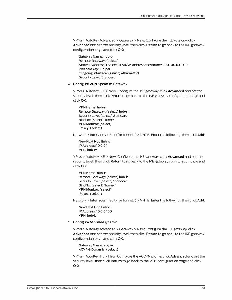
VPNs > AutoKey Advanced > Gateway > New: Configure the IKE gateway, click
Advanced and set the security level, then click Return to go back to the IKE gateway
configuration page and click OK:
Gateway Name: hub-bRemote Gateway: (select)Static IP Address: (Select) IPv4/v6 Address/Hostname: 100.100.100.100Preshare key: JuniperOutgoing interface: (select) ethernet0/1Security Level: Standard
4. Configure VPN Spoke to Gateway
VPNs > AutoKey IKE > New: Configure the IKE gateway, click Advanced and set the
security level, then click Return to go back to the IKE gateway configuration page and
click OK:
VPNName: hub-mRemote Gateway: (select) hub-mSecurity Level (select) StandardBind To: (select) Tunnel.1VPNMonitor: (select)Rekey: (select)
Network > Interfaces > Edit (for tunnel.1) > NHTB: Enter the following, then clickAdd:
NewNext Hop Entry:IP Address: 10.0.0.1VPN: hub-m
VPNs > AutoKey IKE > New: Configure the IKE gateway, click Advanced and set the
security level, then click Return to go back to the IKE gateway configuration page and
click OK:
VPNName: hub-bRemote Gateway: (select) hub-bSecurity Level (select) StandardBind To: (select) Tunnel.1VPNMonitor: (select)Rekey: (select)
Network > Interfaces > Edit (for tunnel.1) > NHTB: Enter the following, then clickAdd:
NewNext Hop Entry:IP Address: 10.0.0.100VPN: hub-b
5. Configure ACVPN-Dynamic
VPNs > AutoKey Advanced > Gateway > New: Configure the IKE gateway, click
Advanced and set the security level, then click Return to go back to the IKE gateway
configuration page and click OK:
Gateway Name: ac-gwACVPN-Dynamic: (select)
VPNs > AutoKey IKE > New: Configure the ACVPN profile, click Advanced and set the
security level, then click Return to go back to the VPN configuration page and click
OK:
351Copyright © 2012, Juniper Networks, Inc.
Chapter 8: AutoConnect-Virtual Private Networks

VPNName: ac-vpnACVPN-Dynamic: (select)Gateway: (select) ac-gw
6. Configuration on Vrouter
Network > Routing > Virtual Router > (for trust-vr) Edit: Do the following:
> NHS Setting > Multiple NHS Setting: Enter the IP address of the NHS server and
click Add, then click Back to NHRP Setting to go back to the NHRP Setting page:
IP: 10.0.0.1IP: 10.0.0.100
> NHS Setting > Cache Setting: Enter the following and click Add, then click Back toNHRP Setting to go back to the NHRP Setting page:
NHS: 192.168.1.0/24
> NHS Setting: Enter the following, then click Apply:
NHC Setting: (select)ACVPNName: (select) ac-vpnEnable: (select)
7. Create RouteMap
Network > Routing > Virtual Router > Route Map > New (for trust-vr): Enter the
following, then click OK:
Map Name: rtmap1Sequence No.: 1Action: permit (select)Match Properties:Interface: (select), tunnel.1
8. Redistribute RIP Routes
Network > Routing > Virtual Router > Edit (for trust-vr) > Edit RIP Instance >
Redistributable Rules: Select the following, then click Add:
Route Map: rtmap1Protocol: OSPF
Network > Routing > Virtual Router > Edit (for trust-vr) > Edit RIP Instance >
Redistributable Rules: Select the following, then click Add:
Route Map: rtmap1Protocol: NHRP
CLI (Spoke1)
set vrouter trust-vr protocol ospf
set interface ethernet0/1 zone untrustset interface ethernet0/1 ip 100.100.100.2/24set interface tunnel.1 zone trustset interface tunnel.1 ip 10.0.0.2/24
set ike gateway hub-m address 100.100.100.1 outgoing-interface ethernet0/1 preshareJuniper sec-level standard
Copyright © 2012, Juniper Networks, Inc.352
Virtual Private Networks
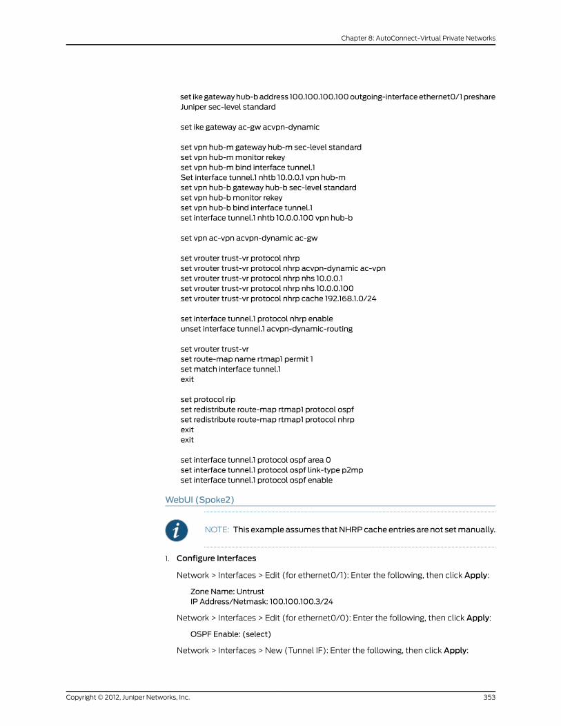
set ikegatewayhub-baddress 100.100.100.100outgoing-interfaceethernet0/1preshareJuniper sec-level standard
set ike gateway ac-gw acvpn-dynamic
set vpn hub-m gateway hub-m sec-level standardset vpn hub-mmonitor rekeyset vpn hub-m bind interface tunnel.1Set interface tunnel.1 nhtb 10.0.0.1 vpn hub-mset vpn hub-b gateway hub-b sec-level standardset vpn hub-bmonitor rekeyset vpn hub-b bind interface tunnel.1set interface tunnel.1 nhtb 10.0.0.100 vpn hub-b
set vpn ac-vpn acvpn-dynamic ac-gw
set vrouter trust-vr protocol nhrpset vrouter trust-vr protocol nhrp acvpn-dynamic ac-vpnset vrouter trust-vr protocol nhrp nhs 10.0.0.1set vrouter trust-vr protocol nhrp nhs 10.0.0.100set vrouter trust-vr protocol nhrp cache 192.168.1.0/24
set interface tunnel.1 protocol nhrp enableunset interface tunnel.1 acvpn-dynamic-routing
set vrouter trust-vrset route-map name rtmap1 permit 1set match interface tunnel.1exit
set protocol ripset redistribute route-map rtmap1 protocol ospfset redistribute route-map rtmap1 protocol nhrpexitexit
set interface tunnel.1 protocol ospf area 0set interface tunnel.1 protocol ospf link-type p2mpset interface tunnel.1 protocol ospf enable
WebUI (Spoke2)
NOTE: This exampleassumes thatNHRPcacheentries arenot setmanually.
1. Configure Interfaces
Network > Interfaces > Edit (for ethernet0/1): Enter the following, then click Apply:
Zone Name: UntrustIP Address/Netmask: 100.100.100.3/24
Network > Interfaces > Edit (for ethernet0/0): Enter the following, then click Apply:
OSPF Enable: (select)
Network > Interfaces > New (Tunnel IF): Enter the following, then click Apply:
353Copyright © 2012, Juniper Networks, Inc.
Chapter 8: AutoConnect-Virtual Private Networks

Tunnel Interface Name: 1Zone (VR): Trust-vrFixed IPIP Address/Netmask: 10.0.0.3/24NHRP Enable: (Select)ACVPN Dynamic Routing: (confirm this not selected)
2. Enable Dymanic Routing (OSPF)
Network > Routing > Virtual Routers > Edit (for trust-vr) > Create OSPF Instance:
Select OSPF Enabled, then click Apply:
Area > Configure (for area 0.0.0.0): Click << Add to move the tunnel.1 interface from
the Available Interface(s) list to the Selected Interface(s) list, then click OK.
Network > Interfaces > Edit (for tunnel.1) > OSPF: Enter the following, then clickApply:
Bind to Area: (select), Select 0.0.0.0 from the drop-down list.Protocol OSPF: EnableLink Type: Point-to-Multipoint (select)
Network > Interfaces > Edit (for ethernet0/1) > OSPF: Enter the following, then click
Apply:
Protocol OSPF: Enable (select)
3. Configure Tunnels to hub-m and hub-b
VPNs > AutoKey Advanced > Gateway > New: Configure the IKE gateway, click
Advanced and set the security level, then click Return to go back to the IKE gateway
configuration page and click OK:
Gateway Name: hub-mRemote Gateway: (select)Static IP Address: (Select) IPv4/v6 Address/Hostname: 100.100.100.1Preshare key: JuniperOutgoing interface: (select) ethernet0/1Security Level: Standard
VPNs > AutoKey Advanced > Gateway > New: Configure the IKE gateway, click
Advanced and set the security level, then click Return to go back to the IKE gateway
configuration page and click OK:
Gateway Name: hub-bRemote Gateway: (select)Static IP Address: (Select) IPv4/v6 Address/Hostname: 100.100.100.100Preshare key: JuniperOutgoing interface: (select) ethernet0/1Security Level: Standard
4. Configure VPN Spoke to Gateway
VPNs > AutoKey IKE > New: Configure the IKE gateway, click Advanced and set the
security level, then click Return to go back to the IKE gateway configuration page and
click OK:
VPNName: hub-mRemote Gateway: (select) hub-mSecurity Level (select) StandardBind To: (select) Tunnel.1
Copyright © 2012, Juniper Networks, Inc.354
Virtual Private Networks

VPNMonitor: (select)Rekey: (select)
Network > Interfaces > Edit (for tunnel.1) > NHTB: Enter the following, then clickAdd:
NewNext Hop Entry:IP Address: 10.0.0.1VPN: hub-m
VPNs > AutoKey IKE > New: Configure the IKE gateway, click Advanced and set the
security level, then click Return to go back to the IKE gateway configuration page and
click OK:
VPNName: hub-bRemote Gateway: (select) hub-bSecurity Level (select) StandardBind To: (select) Tunnel.1VPNMonitor: (select)Rekey: (select)
Network > Interfaces > Edit (for tunnel.1) > NHTB: Enter the following, then clickAdd:
NewNext Hop Entry:IP Address: 10.0.0.100VPN: hub-b
5. Configure ACVPN-Dynamic
VPNs > AutoKey Advanced > Gateway > New: Configure the IKE gateway, click
Advanced and set the security level, then click Return to go back to the IKE gateway
configuration page and click OK:
Gateway Name: ac-gwACVPN-Dynamic: (select)
VPNs > AutoKey IKE > New: Configure the ACVPN profile, click Advanced and set the
security level, then click Return to go back to the VPN configuration page and click
OK:
VPNName: ac-vpnACVPN-Dynamic: (select)Gateway: (select) ac-gw
6. Configuration on Vrouter
Network > Routing > Virtual Router > (for trust-vr) Edit: Do the following:
> NHS Setting > Multiple NHS Setting: Enter the IP address of the NHS server and
click Add, then click Back to NHRP Setting to go back to the NHRP Setting page:
IP: 10.0.0.1IP: 10.0.0.100
> NHS Setting: Enter the following, then click Apply:
NHC Setting: (select)ACVPNName: (select) ac-vpnEnable: (select)
7. Create RouteMap
355Copyright © 2012, Juniper Networks, Inc.
Chapter 8: AutoConnect-Virtual Private Networks
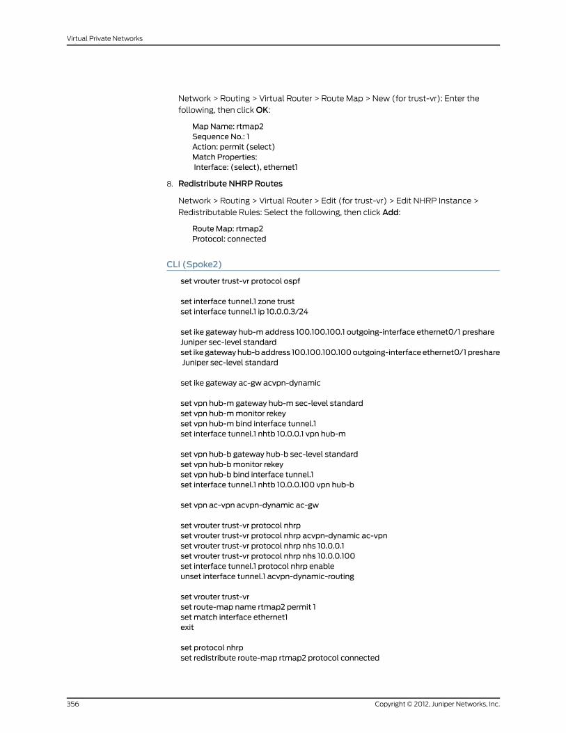
Network > Routing > Virtual Router > Route Map > New (for trust-vr): Enter the
following, then click OK:
Map Name: rtmap2Sequence No.: 1Action: permit (select)Match Properties:Interface: (select), ethernet1
8. Redistribute NHRP Routes
Network > Routing > Virtual Router > Edit (for trust-vr) > Edit NHRP Instance >
Redistributable Rules: Select the following, then click Add:
Route Map: rtmap2Protocol: connected
CLI (Spoke2)
set vrouter trust-vr protocol ospf
set interface tunnel.1 zone trustset interface tunnel.1 ip 10.0.0.3/24
set ike gateway hub-m address 100.100.100.1 outgoing-interface ethernet0/1 preshareJuniper sec-level standardset ike gatewayhub-baddress 100.100.100.100outgoing-interface ethernet0/1 preshareJuniper sec-level standard
set ike gateway ac-gw acvpn-dynamic
set vpn hub-m gateway hub-m sec-level standardset vpn hub-mmonitor rekeyset vpn hub-m bind interface tunnel.1set interface tunnel.1 nhtb 10.0.0.1 vpn hub-m
set vpn hub-b gateway hub-b sec-level standardset vpn hub-bmonitor rekeyset vpn hub-b bind interface tunnel.1set interface tunnel.1 nhtb 10.0.0.100 vpn hub-b
set vpn ac-vpn acvpn-dynamic ac-gw
set vrouter trust-vr protocol nhrpset vrouter trust-vr protocol nhrp acvpn-dynamic ac-vpnset vrouter trust-vr protocol nhrp nhs 10.0.0.1set vrouter trust-vr protocol nhrp nhs 10.0.0.100set interface tunnel.1 protocol nhrp enableunset interface tunnel.1 acvpn-dynamic-routing
set vrouter trust-vrset route-map name rtmap2 permit 1set match interface ethernet1exit
set protocol nhrpset redistribute route-map rtmap2 protocol connected
Copyright © 2012, Juniper Networks, Inc.356
Virtual Private Networks

exitexit
set interface tunnel.1 protocol ospf area 0set interface tunnel.1 protocol ospf link-type p2mpset interface tunnel.1 protocol ospf enableset interface ethernet0/0 protocol ospf enable
357Copyright © 2012, Juniper Networks, Inc.
Chapter 8: AutoConnect-Virtual Private Networks

Copyright © 2012, Juniper Networks, Inc.358
Virtual Private Networks

PART 2
Index
• Index on page 361
359Copyright © 2012, Juniper Networks, Inc.

Copyright © 2012, Juniper Networks, Inc.360
Virtual Private Networks

Index
Symbols3DES...............................................................................................8
AAdvanced Encryption Standard (AES).............................8
aggressive mode......................................................................12
AH................................................................................................4, 7
anti-replay checking.......................................................66, 72
attacks
Replay..................................................................................15
authentication
algorithms.............................................................7, 68, 74
Authentication Header (AH).................................................7
AutoKey IKE VPN.......................................................................9
AutoKey IKE VPN management..........................................9
CCA certificates...................................................................37, 39
Certificate Revocation List...........................................39, 50
loading...............................................................................39
certificates...................................................................................9
CA..................................................................................37, 39
loading................................................................................43
loading CRL......................................................................39
local.....................................................................................39
requesting..........................................................................41
revocation.................................................................39, 50
via email.............................................................................41
Challenge Handshake Authentication ProtocolSee
CHAP
CHAP.................................................................................213, 218
CRL See Certificate Revocation List
cryptographic options............................................................61
anti-replay checking..............................................66, 72
authentication algorithms...................................68, 74
authentication types.............................................63, 70
certificate bit lengths............................................63, 70
dialup..................................................................................69
encryption algorithms...........................................64, 74
ESP................................................................................67, 73
IKE ID.............................................................................65, 71
IPsec protocols................................................................73
key methods....................................................................62
PFS...............................................................................66, 72
Phase 1 modes.........................................................63, 69
site-to-site .......................................................................62
DData Encryption Standard (DES).......................................8
DES.................................................................................................8
DH
IKEv2...................................................................................20
Diffie-Hellman..........................................................................13
digital signature.......................................................................35
DIP pools
extended interfaces....................................................148
NAT for VPNs..................................................................147
distinguished name (DN)....................................................191
DN................................................................................................191
DNS, L2TP settings...............................................................217
EEAP messages...........................................................................31
Encapsulating Security Payload See ESP
encryption
algorithms............................................................8, 64, 68
ESP........................................................................................4, 7, 8
exchanges
CHILD_SA...........................................................................14
informational...................................................................20
initial...................................................................................20
Extensible Authentication Protocol
passthrough...........................................................................31
Ggroup IKE ID
certificates.......................................................................192
preshared keys..............................................................201
Hhash-based message authentication code.....................7
HMAC..............................................................................................7
IIKE..........................................................................9, 97, 105, 170
group IKE ID user...........................................................191
heartbeats......................................................................303
hello messages............................................................303
IKE ID.............................................................................65, 71
IKE ID recommendations............................................82
361Copyright © 2012, Juniper Networks, Inc.

IKE ID, Windows 2000................................................215
Phase 1 proposals, predefined....................................11
Phase 2 proposals, predefined..................................14
proxy IDs.............................................................................14
redundant gateways..................................................302
remote ID, ASN1-DN....................................................194
shared IKE ID user.......................................................206
IKEv2
Diffie-Hellman................................................................20
EAP passthrough.............................................................31
enabling.............................................................................20
enabling on a security device....................................26
messages...........................................................................31
SA.........................................................................................20
informational exchanges.....................................................20
initial exchanges.....................................................................20
interfaces
extended..........................................................................148
null.......................................................................................96
Internet Key Exchange
See IKE
Internet Key Exchange version 2 See IKEv2
Internet Protocol (IP) addresses See IP addresses
IP addresses
extended..........................................................................148
IP security See IPsec
IPsec
AH....................................................................................3, 73
digital signature..............................................................35
ESP..................................................................................3, 73
L2TP-over-IPsec...............................................................5
passthrough traffic...........................................328, 329
SAs.......................................................................3, 10, 11, 14
SPI..........................................................................................3
transport mode......................................5, 213, 219, 224
tunnel....................................................................................3
tunnel negotiation...........................................................11
Kkeepalive
frequency, NAT-T........................................................246
L2TP..................................................................................222
keys
manual.....................................................................127, 133
preshared.........................................................................170
LL2TP...........................................................................................213
access concentrator\
See LAC
bidirectional....................................................................213
compulsory configuration.........................................213
decapsulation................................................................216
default parameters.......................................................217
encapsulation................................................................215
hello signal............................................................222, 224
Keep Alive..............................................................222, 224
L2TP-only on Windows 2000.................................215
network server\
See LNS
operational mode.........................................................215
RADIUS server................................................................217
ScreenOS support........................................................213
SecurID server................................................................217
tunnel................................................................................219
voluntary configuration..............................................213
Windows 2000 tunnel
authentication.................................................222, 224
L2TP-over-IPsec....................................................5, 220, 224
bidirectional....................................................................213
tunnel................................................................................219
LAC..............................................................................................213
NetScreen-Remote 5.0..............................................213
Windows 2000..............................................................213
Layer 2 Tunneling Protocol
See L2TP
LNS..............................................................................................213
local certificate........................................................................39
Mmain mode.................................................................................12
Manual Key
management.....................................................................9
manual keys....................................................................127, 133
MD5............................................................................................7, 8
Message Digest version 5 (MD5).........................................7
messages
EAP.......................................................................................31
IKEv2....................................................................................31
MIB files, importing..............................................................262
MIP, VPNs.................................................................................147
modes
aggressive..........................................................................12
L2TP operational..........................................................215
main......................................................................................12
Copyright © 2012, Juniper Networks, Inc.362
Virtual Private Networks

Phase 1 cryptographic..................................................63
transport...................................................5, 213, 219, 224
modulus.......................................................................................13
NNAT
IPsec and NAT................................................................241
NAT servers.....................................................................241
NAT-dst
VPNs..................................................................................147
NAT-src
VPNs.................................................................................149
NAT-T.........................................................................................241
enabling..........................................................................249
IKE packet......................................................................244
initiator and responder...............................................247
IPsec packet..................................................................245
keepalive frequency...................................................246
obstacles for VPNs.....................................................244
probing for NAT............................................................242
NAT-T IKE
passthrough traffic.....................................................328
NAT-Traversal
See NAT-T
NetScreen-Remote
AutoKey IKE VPN..........................................................170
dynamic peer.........................................................175, 182
NAT-T option.................................................................241
NHTB table.............................................................................263
addressing scheme....................................................265
automatic entries.........................................................267
manual entries.............................................................266
mapping routes to tunnels......................................264
Non-NAT-T IKE
passthrough traffic.....................................................329
null route....................................................................................96
OOCSP (Online Certificate Status Protocol)..................50
client...................................................................................50
responder..........................................................................50
Ppacket flow
inbound VPN....................................................................79
inbound VPN<$endrange>.......................................80
outbound VPN.................................................................79
policy-based VPN ..........................................................81
policy-based VPN <$endrange>..............................81
route-based VPN ...........................................................77
route-based VPN <$endrange>..............................80
PAP.....................................................................................213, 218
Password Authentication Protocol See PAP
Perfect Forward Secrecy
See PFS
PFS..................................................................................15, 66, 72
Phase 1..........................................................................................11
proposals.............................................................................11
proposals, predefined.....................................................11
Phase 2........................................................................................14
proposals.....................................................................13, 14
proposals, predefined...................................................14
PKI.................................................................................................37
Point-to-Point Protocol
See PPP
policies
bidirectional VPNs........................................................133
policy-based VPNs.................................................................75
PPP.............................................................................................213
preshared key..............................................................................9
preshared keys........................................................................170
proposals
Phase 1..........................................................................11, 82
Phase 2........................................................................14, 82
protocols
CHAP.................................................................................213
PAP.....................................................................................213
PPP.....................................................................................213
proxy IDs......................................................................................14
matching....................................................................75, 82
VPNs and NAT................................................................147
Public key infrastructure See PKI
Public/private key pair..........................................................39
RRADIUS
L2TP...................................................................................217
redundant gateways...........................................................302
recovery procedure.....................................................306
TCP SYN flag checking..............................................307
rekey option, VPN monitoring..........................................252
replay protection......................................................................15
request/response pairs..........................................................21
route-based VPNs..................................................................76
routes
null.......................................................................................96
363Copyright © 2012, Juniper Networks, Inc.
Index

SSAs.....................................................................................10, 11, 14
check in packet flow......................................................77
SCEP (Simple Certificate Enrollment
Protocol)...............................................................................46
Secure Hash Algorithm-1
See SHA-1
SecurID
L2TP...................................................................................217
security associations See SAs
IKEv2...................................................................................20
SHA-1.........................................................................................7, 8
SKEYSEED..................................................................................21
SNMP
MIB files, importing.....................................................262
VPN monitoring............................................................262
TTCP
SYN flag checking.......................................................307
transport mode...............................................5, 213, 219, 224
Triple DES See 3DES
tunnel mode................................................................................6
UUDP
checksum.......................................................................246
NAT-T encapsulation..................................................241
users
group IKE ID.....................................................................191
shared IKE ID.................................................................206
VVPN monitoring......................................................................251
destination address ...................................................253
destination address <$endrange>.......................255
destination address, XAuth.....................................254
ICMP echo requests....................................................262
outgoing interface ......................................................253
outgoing interface <$endrange>..........................255
policies............................................................................254
rekey option..........................................................252, 267
routing design.................................................................84
SNMP...............................................................................262
status changes....................................................251, 254
VPNs
aggressive mode..............................................................12
AutoKey IKE........................................................................9
configuration tips...........................................................82
configuration tips<$endrange>...............................82
cryptographic options...................................................61
Diffie-Hellman exchange.............................................13
FQDN aliases.................................................................138
FQDN for gateways......................................................137
main mode.........................................................................12
MIP......................................................................................147
multiple tunnels per tunnel interface..................263
NAT for overlapping addresses...............................147
NAT-dst............................................................................147
packet flow .......................................................................77
packet flow <$endrange>...........................................81
Phase 1..................................................................................11
Phase 2................................................................................14
proxy IDs, matching.......................................................82
redundant gateways..................................................302
redundant groups, recovery procedure..............306
replay protection.............................................................15
route- vs policy-based..................................................75
SAs.......................................................................................10
transport mode.................................................................5
tunnel always up..........................................................252
VPN groups....................................................................302
VPN monitoring and rekey.......................................252
WWINS
L2TP settings..................................................................217
XXAuth
VPN monitoring............................................................254
Copyright © 2012, Juniper Networks, Inc.364
Virtual Private Networks