concept design and in vitro evaluation of a novel - diva portal
TRANSCRIPT

1
Concept Design and In Vitro Evaluation of a Novel Dynamic Displacement Ventricular Assist Device
A licentiate thesis in Technology and Health by: Mattias Stenberg
Stockholm 2006
This project has been performed in close collaboration with the Departments of Cardiothoracic Surgery, Biomedical, and Mechanical and Aerospace Engineering at the
University of Florida, USA

2
Copyright © Mattias Stenberg, Sweden, 2006
Printed in Sweden by Universitetsservice US-AB

3
Abstract
Ventricular Assist Devices (VADs) are mechanical pumps used to off-load a deceased
heart, primarily in late stage congestive heart failure patients. VAD employment may
facilitate cardiac recovery, but most often provides time before a suitable heart
transplant can be found. Lately, long term use VAD systems have been introduced as
an alternative to a heart transplant.
Traditionally, design of VADs has employed either displacement based pump
technologies or radial-flow pumps, also known as rotodynamic pumps. A
displacement pump induces a mechanical force on a fluid contained within a defined
space, hence giving it motion. Radial-flow pumps impart momentum to a fluid, most
often by placing a rotating device in the fluid.
This thesis introduces a novel pumping concept, combining features from both
displacement and radial-flow pumps. A first prototype, the Vivicor™ pump, has been
designed, fabricated and evaluated In Vitro, the results reported in this thesis.
The In Vitro evaluation of the Vivicor™ pump provides evidence of a pump with
mechanical self-regulation based on pump pre-load level, much like a displacement
pump. The Vivicor™ pump also displays pulsating outflow in combination with an
inflow both during pump systole and diastole. The latter provides potential advantages
over traditional displacement pumps as smaller cannulae or catheters can be used,
facilitating miniaturization. Continuos filling throughout the pumping cycle also
require less pressure to be exerted on the fluid, compared to displacement pumps,
limiting the risk of mechanical damage to the pumped fluid. The In Vitro evaluation
has also provided further insights on necessary design modifications in the second-
generation Vivicor™ prototype, currently planned. The Vivicor™ pumping technology
is highly interesting for further development and evaluation for use in ventricular
assist applications.
Key words: Ventricular Assist Devices, Artificial Heart, Heart Failure, InVitro
evaluation

4

5
To Sigfrid - Ever the inspiration and role model.

6
Preface
This thesis is submitted to the Royal Institute of Technology in partial fulfillment of
the requirement for a degree of Licentiate of Technology and Health. The work has
been performed at University of Florida, Departments of Cardiothoracic Surgery,
Biomedical Engineering, and Mechanical and Aerospace Engineering.
Quite early on I found myself very interested in the multi-disciplinary field of
biomedical engineering, the possibility of combining the best out of two worlds.
During my last years as a Master’s student at the Royal Institute of Technology in
Stockholm, I was introduced to Ventricular Assist Devices (VADs), a therapy area in
which pumps were used to mechanically support the failing heart. In 1999, when I
was presented with the offer of doing my degree work in biomedical engineering at
the AeMES department at the University of Florida, I accepted. The project I was
going to carry out was very interesting, developing a concept design of a new
Ventricular Assist Device. During this process I had the chance to experience first
hand the life turning effect of VADs on patients that were clinging to life and some
still to hope. Needless to say, this had a tremendous impact on me, and became the
beginning of my love for cardiology and cardiac engineering.
Since, I have had the chance to continue working with medical devices, both
technically and clinically, as well as from a business development point of view. This
has been a tremendous learning experience and has allowed me to work with a
multitude of medical technology applications, ranging from biodegradable implants to
software for diabetic retinopathy screening.
In January 2004 I returned to University of Florida as an exchange student to pursue a
Licentiate degree at the Royal Institute of Technology, along with continuing the
development and testing of the VAD design that originated in 1999, now known as
the Vivicor™ pump*. To date this work has resulted in, apart from this licentiate
thesis, two patent applications. One utility patent application pertaining to the
pumping mechanism of the Vivicor™ pump, and a second provisional patent

7
application addressing the use of the Vivicor™ pumping mechanism in an external
pump platform for short to intermediate term ventricular assist.
Even if this present licentiate project is a very modest one, I am hopeful that the
Vivicor™ pump will continue to yield more promising results and continue on its long
but promising way towards a commercial product. Also, I sincerely hope that this
project has created an interest in many others for VADs and other device related
therapies. Hopefully they too will choose the rewarding field of biomedical
engineering.
Mattias Stenberg
Gainesville, May 2005
* The Vivicor™ name is a montage of the Latin words “Vivificus”, and “Cor” for
“live-giving, life-restoring” and “Heart”, respectively

8
Table of Content
1. AIMS OF THE STUDY.................................................................................................................9
2. BACKGROUND ..........................................................................................................................11
2.1. THE HEART.....................................................................................................................................11 2.2. HEART DISEASE..............................................................................................................................12 2.3. AN INTRODUCTION TO VENTRICULAR ASSIST DEVICE THERAPY ....................................................15 2.4. THE HISTORY OF VENTRICULAR ASSIST DEVICES ..........................................................................19
3. CLASSIFICATION OF VENTRICULAR ASSIST DEVICES...............................................22
3.1. PUMPING TECHNOLOGY ..................................................................................................................22 3.2. THERAPEUTIC OBJECTIVE ...............................................................................................................41 3.3. OUTPUT CHARACTERISTICS.............................................................................................................44
4. CURRENT VENTRICULAR ASSIST DEVICES....................................................................46
4.1. ADVANTAGES / DISADVANTAGES OF CURRENTLY FDA APPROVED VAD SYSTEMS........................47 4.2. ADVANTAGES / DISADVANTAGES OF FUTURE VAD SYSTEMS .........................................................52
5. THE DYNAMIC DISPLACEMENT PUMP.............................................................................60
5.1. CONCEPT DESIGN ...........................................................................................................................60 5.2. PROTOTYPE SYSTEM COMPONENT DESIGN, FABRICATION, AND ACTUATION.................................67
6. IN VITRO EVALUATION .........................................................................................................75
6.1. EXPERIMENT 1 - CHARACTERIZATION OF PUMP IN/OUTLET PRESSURE ............................................75 6.2. EXPERIMENT 2 - CHARACTERIZATION OF PRE-LOAD RESPONSIVENESS ...........................................77 6.3. EXPERIMENT 3 - CHARACTERIZATION OF MEAN OUTPUT VS FREQUENCY .......................................78 6.4. EXPERIMENT 4 - CHARACTERIZATION OF PUMP IN/OUTLET FLOW...................................................79
7. DISCUSSION AND CONCLUSIONS .......................................................................................81
7.1. EXPERIMENT 1 - CHARACTERIZATION OF PUMP IN/OUTLET PRESSURE ............................................81 7.2. EXPERIMENT 2 - CHARACTERIZATION OF PRE-LOAD RESPONSIVENESS ...........................................82 7.3. EXPERIMENT 3 - CHARACTERIZATION OF MEAN OUTPUT VS FREQUENCY .......................................83 7.4. EXPERIMENT 4 - CHARACTERIZATION OF PUMP IN/OUTLET FLOW...................................................85 7.5. CONCLUSIONS.................................................................................................................................86
8. FUTURE WORK AND DEVELOPMENT ...............................................................................88
8.1. SHORT TERM OBJECTIVES ...............................................................................................................88 8.2. LONG TERM OBJECTIVES .................................................................................................................89
9. ACKNOWLEDGEMENTS.........................................................................................................91
10. REFERENCES.............................................................................................................................92
11. VAD COMPANY WEB LINKS .................................................................................................95
APPENDIX A - AUTOCAD ASSEMBLY DRAWING AND COMPONENT LIST .....................96
APPENDIX B - LABVIEW DATA ACQUISITION CODE ............................................................98
APPENDIX C - LABVIEW MOTOR CONTROLLER CODE.......................................................99

9
1. Aims of the Study
Two pumping technologies exist in current design of Ventricular Assist Devices and
general-purpose blood pumps; Displacement pumps and Radial-flow pumps.
Displacement pumps are greatly large in size, excluding many patients from use, but
they are easy to control due to their relative insensitivity to changing pre- and after-
load conditions. Radial-flow pumps are generally much smaller, even allowing for
pediatric use, but they are more difficult to control due to their high sensitivity to
changing pre- and after-load conditions. In addition Displacement pumps produce a
pulsating outflow, contrary to Radial-flow pumps, which allows for counter pulsation
operation. Pulsating outflow is today the most researched method of support. The
long-term effects of non-pulsating support are still unknown.
The challenge of this licentiate project has been to merge the advantages of
Displacement pumps and Radial-flow pumps into a novel pump design, designing a
pulsating outflow pump that allows for a high degree of miniaturization.
The objectives of this report and underlying licentiate work are twofold:
I. Competitive landscape overview:
Provide an overview of current products used as Ventricular Assist Devices
and a system of classification of the different pumping technologies used in
the design of current Ventricular Assist Devices (VADs).
II. Technical proof-of-concept:
Design, fabricate first-generation prototype, and characterize a novel VAD
concept In Vitro (by evaluating the pressure, output, and in/outflow
characteristics), based on the mechanical pumping mechanism of the human
heart.
Initial work will include studying previous technologies and methods used in the
design of VADs. This will be done through extensive literature searches and first hand

10
experience gained through shadowing the VAD program at the Department of
Cardiothoracic Surgery, University of Florida.
A conceptual design of a first-generation In Vitro VAD prototype, incorporating an
oscillating Atrio-Ventricular valve plane to mimic the mechanical pumping
mechanism of the human heart, as previously discussed by Lundbäck [1] and Stenberg
[2], will be created. The detailed component level design will be visualized by method
of Computer Aided Design and a full-scale model will be fabricated using rapid
prototyping techniques.
In Vitro testing of the first-generation prototype will be carried out at the Department
of Cardiothoracic Surgery, University of Florida, using a closed loop circulatory
system.
In short, the specific tasks of this study are:
I. Literature search and clinical shadowing
II. Develop new design concept and individual component design
III. Visualize new design concept, using CAD design tools
IV. Fabricate a prototype of the new design concept, using rapid fabricating
techniques
V. Characterization of prototype mechanical performance, i.e., prototype In Vitro
testing of pressure, output and in/outflow characteristics

11
2. Background 2.1. The Heart Located in the middle mediastinum between the lungs, the heart is the central part of
the human circulatory system. The human heart consists of four chambers. Each side
of the heart, consisting of two of those chambers, one atrium and one ventricle, can be
viewed upon as a mechanical pump.
The right part of the heart sustains circulation to the lungs, by pumping blood from
the right ventricle through the pulmonary valve, the pulmonary arteries, via the lungs
and then back to the left part of the heart. The left part of the heart sustains circulation
to the extremities and other organs and is called the systemic circulatory system. This
is circled by blood pumping from the left ventricle, through the aortic valve, the aorta,
the arteries and capillary system and then back to the right side of the heart via the
venous system and the superior and inferior vena cava (Fig1).
Figure 1: Pulmonary and Systemic circulation as presented by Jacobson [3] (Translation by M.
Stenberg), and the coronary arteries of the heart as presented by Marieb [4]
The heart itself is a muscle and is provided with oxygen by the coronary arteries
(Fig1). Sometimes the heart suffers from decease or injury, reducing the pumping
capacity of the heart. This can be the result of congenital heart decease, cardiogenic
shock, myocardial infarct or infection, and a number of other reasons.
12
2.2. Heart Disease 2.2.1. Congestive heart failure According to the National Heart, Lung and Blood Institute [5], an estimated 4,8
million Americans suffer from Congestive Heart Failure (CHF), a condition in which
the heart cannot pump enough blood to meet the need of the body’s other organs. The
heart grows too large as a result of congestion in the tissues, which also affect the
lungs and extremities such as the legs. CHF is a chronic condition and is often the
end-stage of cardiac disease. Half of all patients diagnosed with CHF will be dead
within 5 years. The disease is present in 10% of all persons over 70 years of age and
each year there are an estimated 400000 new cases in the US alone.
The New York State Heart Association (NYSHA) has established a classification
system for CHF. It is a classification system that is based upon the severity of the
symptoms associated with CHF. In each class the patient has already been diagnosed
with CHF. The NYSHA classes, or “stages”, are:
- Class I – No limitation of physical activity. Ordinary physical activity does not
cause excess fatigue, shortness of breath, or palpitations.
- Class II – There is slight limitation of physical activity. Patients are comfortable at
rest but ordinary physical activity results in fatigue, shortness of breath,
palpitations or angina.
- Class III – There is marked limitation of physical activity. Although patients are
comfortable at rest, even less than ordinary activity will result in symptoms.
- Class IV – There is inability of the patient to carry out any physical activity
without significant discomfort. Symptoms of congestive heart failure are present
even when patient is at rest. With any physical activity, increased discomfort is
experienced by the patient.
A new classification system for CHF was released by the American College of
Cardiology (ACC) and American Heart Association (AHA) in November of 2001.
The new system of classification is not limited to patients already diagnosed with

13
CHF. As such, it is designed to be used in conjunction with the NYSHA classification
system, rather than as a substitute. The ACC/AHA classes are:
- Class A – The patient is at risk for developing CHF, but has no structural disorder
of the heart. These would include patients at high risk for CHF due to the presence
of hypertension, coronary artery disease, diabetes mellitus, a history of drug or
alcohol abuse, a history of rheumatic fever, a history of cardiomyopathy, etc.
- Class B – The patient has a structural disorder of the heart but has never
developed CHF. This would include patients with structural heart disease such as
left heart enlargement, heart fibrosis, valve disease, or a previous heart attack.
- Class C – The patient has current or past CHF symptoms and underlying structural
heart disease.
- Class D – The patient has end-stage disease and is frequently hospitalized for
CHF, or requires special treatments such as a left ventricular assist device
(LVAD), artificial heart, inotropic infusion, heart transplant, or hospice care.
Treatment options are limited. Drugs, such as diuretics, ACE inhibitors and digitalis
are primary therapy and are used to either expand blood vessels or eliminate access
salt and water in the body. For patients with late-stage CHF current treatment options
are limited. Excluding the use of cardiac assist technologies such as Ventricular Assist
Device systems, the only viable treatment option available today is a heart transplant.
In recent years, according to the American Heart Association [6], the number of
available donors has stabilized at 2200 per year. However, with the benefits of better
health care, more CHF patients are reaching late-stage status, further increasing the
need for transplants. As a result, the gap between the number of available donors and
the number of patients on the transplant list has doubled in the last 10 years, reaching
close to 5000 patients in the US alone. But even this figure misrepresents the actual
need for late-stage treatment, as the screening criteria for acceptance to the transplant
waiting list are immediately disqualifying roughly 50% of all patients. Calculations by
the American Heart Association [6] show that the actual number of US patients in
need of late-stage treatment is 40000, counting only those 65 years old or younger.

14
Key to all of this is the understanding that CHF is a highly prevalent, chronic disease,
with limited treatment options and a very high cost of care on a global basis.
American Heart Association data [6] puts cost of care for CHF patients at $20B
annually in the US. Actual dollars could be as high as $30-35B given the overlap with
other cardiovascular disease states. Anecdotal data suggests that the per capita
spending in Europe is even higher.
2.2.2. Myocardial Infarction Myocardial Infarction (MI) is what is commonly referred to as a heart attack. An MI
occurs when blood flow through one or more of the coronary arteries is obstructed,
depriving the heart muscle of oxygen. The result of the occlusion is necrosis, or tissue
death, of the heart muscle tissue in the area of the myocardium previously fed by the
occluded coronary artery. In a vast majority of MI cases, the occlusion is a result of an
acute blood clot, resulting from the rupture of fatty deposits known as “plaque” lining
the walls of the coronary arteries, whereas previously the deposit had only partially
obstructed the flow of the blood vessel.
The ability of the heart to function as a mechanical pump following an MI is directly
related to the extent of the myocardial damage. MI is predominantly a condition of the
left ventricle, although functional damage may extend to the right ventricle or to the
atrium. Significant myocardial damage may be indicative of the need for circulatory
assistance in itself. More importantly, an MI may cause a down spiraling cascade of
events that may result in CHF.
Experiencing an MI places a burden on the whole heart in a way that may eventually
result in right ventricular abnormalities, and tricuspid valve regurgitation. If the
tricuspid valve regurgitation becomes significant, blood flows backwards in the heart
and not enough is pumped forward. As a result the damaged left ventricle has to pump
even harder and faster to get oxygenated blood out to the tissues. This causes extra
stress, which causes extra damage, and remodeling of the left ventricle, escalating the
stages of CHF.

15
2.2.3. Cardiogenic Chock
Cardiogenic shock is best described as a decreased pumping ability of the native
heart, causing a shock like state characterized by inadequate perfusion to the tissues.
Cardiogenic shock usually occurs in conjunction with, or as a direct result of,
ischemic damage to the heart muscle. Clinically, Cardiogenic shock is generally
characterized by a systolic blood pressure less than 80 mm Hg, a cardiac index less
than 1,8 l / min / m2, and a pulmonary capillary wedge pressure greater than 18 mm
Hg [7]
Cardiogenic shock is most often initiated by an acute myocardial infarction. Heart
muscle damaged by the infarction loses its contractility. Once 40% of the heart
muscle is effected, Cardiogenic shock may result. On a mechanical level, a marked
decrease in contractility reduces the ejection fraction and cardiac output. These lead to
increased ventricular filling pressures, cardiac chamber dilatation, and ultimately uni-
ventricular or bi-ventricular failure that result in systemic hypotension and/or
pulmonary edema.
2.2.4. Myocardial Infection
Infection can be an important cause of dilated cardiomyopathy. This is usually the
result of acute myocarditis, or infection of the heart muscle. Infection may also effect
the endocardium, native or prosthetic valves, or the cardiac conduction system. CHF
symptoms usually do not present until several weeks after the initial infection, due to
a suggested immunologic mechanism for development of systolic dysfunction.
The most common viral cause of myocarditis is coxsackievirus B, but at least two
dozen others, including hepatitis viruses, adenovirus, arbovirus, cytomegalovirus,
echovirus, influenza virus, and HIV, are also possibilities.
2.3. An Introduction to Ventricular Assist Device therapy
In situations like those discussed in section 2.2, therapy may include the need to
mechanically assist the heart, by reducing the cardiac workload and sustain systemic

16
and coronary circulation. Usually three different situations can be identified, where
mechanical pumps are used for this purpose.
First, where the primary objective is to sustain systemic circulation. This may be the
case in end stage heart decease where the heart can not be saved. The patient is given
circulatory assist, while waiting for a donor heart suitable for transplantation. This is
most often referred to as bridge-to-transplant.
The second situation usually occurs in patients with cardiogenic shock, myocardial
infection or after a myocardial infarct. The objective here is to try and save the heart
by reducing the workload and/or increase coronary circulation, hence providing the
heart with more oxygen. This may provide the heart with sufficient time and
circulation to recover. As a consequence, this therapeutic approach is most often
referred to as bridge-to-recovery. This approach may mean not giving priority to the
systemic circulation.
Finally, circulatory heart assist may be indicated in a situation where all other
therapeutic avenues have been exhausted. This is an embryonic therapeutic field
where typically end stage heart failure patients, that are ineligible for other therapies
such as a heart transplant, receive permanent circulatory heart assist. This is most
often referred to as alternative-to-transplant, or destination therapy.
In order to assist the deceased heart, different types of mechanical pumps are used.
However, these are collectively referred to as Ventricular Assist Devices, VADs. A
VAD system generally consists of the actual pump (the VAD), a control unit and a
power supply.
The control unit controls the way in which the pump works. Control is maintained by
continuous monitoring of a number of physiological and physical parameters. Usually
three different types of control modes are used in VADs that provide a pulsating
output (the difference between pulsating and constant output VAD products will be
addressed in more detail in chapter 3). These are Fixed Rate Asynchronous mode,
Full-to-Empty Asynchronous mode, and Synchronization mode.

17
The Fixed Rate asynchronous mode maintains a continuous pumping rate, preset by
the operator. Depending on variations in workload this mode provides variable stroke
volume.
In the Full-to-Empty Asynchronous mode, the pump is allowed to completely fill up
before the blood is ejected. Hence, the pumping rate varies with changes in pre-load
to the pump and is not correlated to the heart rate of the native heart. This mode
provides constant stroke volume.
The Synchronization mode allows the pumping rate to be set by an actual
physiological parameter, usually the R-wave of the ECG. By programmable time
delay the pump can be brought to work in counter pulsation to the heart. This mode
provides variable rate and variable stroke volume.
The VAD, is the actual pump performing the fluid actuation work. The VAD may be
implantable or located outside the patient’s body. Most intermediate to long term
VADs are connected to the heart through cannulae. In left ventricular assist devices,
LVADs, where the left heart is being assisted, the inlet of the VAD is connected to the
heart via an apical cannulae or a ventricular apex cannulae. Blood is returned to the
patient by an arterial cannulae, usually connected to the ascending aorta. VADs may
also be used for assisting the right heart, RVADs, or as simultaneous assist of both the
left and right heart. The latter are referred to as Bi-Ventricular Assist Devices,
BIVADs (Fig2a and 2b).

18
LVAD BIVAD RVAD Figure 2a: Schematic overview of cannulation approaches for LVAD, BIVAD, and RVAD
respectively (M Stenberg)
Figure 2b: Illustration of LVAD and RVAD (BVAD) support using cardiac cannulae (M Stenberg)
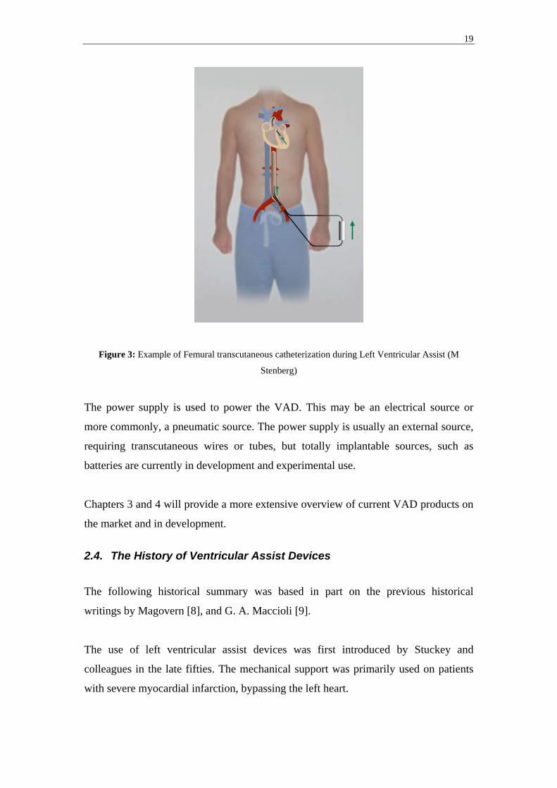
Some VAD products also allow for the use of transcutaneous catheters to facilitate
minimal invasive insertion. This is more common in short to intermediate term
applications and in pumps that provide a constant in / out flow. Various insertion
techniques are used to guide the catheters to the desired heart chambers. However, the
most common access point for catheters is through the Femoral arteries that will allow
for retrograde catheterization of the left heart (Fig3). Please observe that multiple
variations exist.
RVAD LVAD
19
Figure 3: Example of Femural transcutaneous catheterization during Left Ventricular Assist (M
Stenberg)
The power supply is used to power the VAD. This may be an electrical source or
more commonly, a pneumatic source. The power supply is usually an external source,
requiring transcutaneous wires or tubes, but totally implantable sources, such as
batteries are currently in development and experimental use.
Chapters 3 and 4 will provide a more extensive overview of current VAD products on
the market and in development.
2.4. The History of Ventricular Assist Devices
The following historical summary was based in part on the previous historical
writings by Magovern [8], and G. A. Maccioli [9].
The use of left ventricular assist devices was first introduced by Stuckey and
colleagues in the late fifties. The mechanical support was primarily used on patients
with severe myocardial infarction, bypassing the left heart.

20
Soon the applications of mechanical assistance grew, and in the sixties left ventricular
assistance was introduced by Liotta as a way of circulatory assistance in patients that
could not be weaned from cardiopulmonary bypass. Pneumatic ventricular assist
devices were developed by Norman at Texas Heart Institute and Boston based
Bernhard, but long-term patient survival was low. However, the use of roller pumps
and centrifugal pump systems produced better survival rates, long- and short term, in
patients suffering from post-cardiotomy cardiogenic shock.
The use of mechanical assistance in order to increase coronary flow was first
introduced in the early fifties. Kantrowitz realized that if blood could be diverted to
the coronary arteries during diastole of the heart, when the intramyocardial pressure
was lower, the coronary blood flow would increase [10]. This technique became
known as Counter Pulsation. This technique eventually led to the invention of the
intra-aortic balloon pump. The intra-aortic balloon pump has today become one of the
most frequently used therapeutic techniques in patients suffering from cardiogenic
shock due to recent myocardial infarction.
Mechanical support was first introduced as a bridge to transplant in the late seventies,
and good long-term survival rates were not found in that application until the mid
eighties. The procedure was pioneered by Stanford University, but Hill and associates
were the first ones to report a successful procedure, using the Thoratec Pierce-
Donachy VAD [11]. Today this application is widespread, using VADs to provide
circulatory assistance in patients with end stage heart decease. Totally implantable
systems are being developed for long-time use, ranging up to several years of
consistent use.
Today, the use of Ventricular Assist Devices has become an established practice,
specifically in the United States. The clinical acceptance of VAD based therapy was
further facilitated by the recent publishing of encouraging results from the
REMATCH (Randomized Evaluation of Mechanical Assistance for the Treatment of
Congestive Heart Failure) trial.
The REMATCH trial was designed to investigate the effectiveness of VAD therapy as
compared to pharmaceutical intervention in congestive heart failure patients. 129

21
patients with NYHA (New York Heart Association) class IV heart failure symptoms
for more than 90 days, receiving ACE inhibitors, digoxin and beta blockers, with a
left ventricular ejection fraction of ≤ 25% were randomized to receive a Thoratec
HeartMate XVE LVAD, or purely optimal medical management with beta blockers
and spironolactone.
12 months into the trial, 25% of the patients receiving optimal medical management
remained alive. At 24 months only 8% of the patients in the same group were alive. In
the LVAD group, the corresponding survival rates were 48% at 12 months and 23% at
24 months, representing a relative risk reduction of death of 48% over the two year
period. However, it must be remembered that the magnitude of this reduction must be
viewed in the context of the much greater complexity of VAD therapy compared to
drug therapy [12].
However, although showing promising results in terms of survival rates, patients
receiving LVAD therapy were more than twice as likely to experience a serious
adverse event as those on optimal medical management alone, predominantly
infection, bleeding and device malfunction [13], which remains the key improvement
areas for VAD therapies to date.

22
3. Classification of Ventricular Assist Devices
A vast number of different designs have been used for design of Ventricular Assist
Devices through the years. Even though some designs are no longer in use we know
too little of the constraints and parameters influencing the final results to deem one
specific design right or wrong. This is why today there still exist a large number of
different designs and pumping technologies used in the construction of VADs. An
increasing number of different identifiable therapeutic needs in patients with
congenital or reversible heart decease also motivates the use of a large number of
VADs of different designs.
This chapter aims to expand on three different ways of classifying VADs:
- Pumping technology
- Therapeutic objective
- In / Outflow characteristic
This chapter will also provide selected examples of past and current VAD systems to
illustrate the variety of pumping technologies used in VAD design.
3.1. Pumping technology
Traditionally, design of blood pumps and specifically Ventricular Assist Devices has
employed either Displacement based pump technologies or Radial-flow pumps, also
known as Dynamic or Rotodynamic pumps [14]. The following chapter will briefly
expand on the difference between Displacement pumps and Radial-flow pumps, along
with illustrating these pumping technologies by presenting a representative selection
of VAD products currently on the market or in clinical trials, based on these
technologies (Table1). Where not otherwise referenced, pumps specific information
has been collected from pump company websites (please refer to chapter 11 for
complete website addresses).

23
Application Technology Design variant Product examples
Push-plate pumps Novacor, World Heart
Membrane (sac or diaphragm) pumps
- Heartmate, Thoratec
- Pierce-Donachy, Thoratec
- BVS5000, Abiomed
Peristaltic pumps None in clinical use
Balloon pumps CS100, DataScope
Displacement pumps
Roller pumps N/A (As part of other products)
Centrifugal pumps - Biopump, Medtronic
- Cancion CRS, Orqis
- Heartmate III, Thoratec
Blood pumps
Radial-flow pumps
Rotary pumps (Impeller) - Hemopump, Medtronic
- Impella, Cardiotechnik
- DeBakey, Micromed Technologies
- Jarvik 2000, Jarvik Heart
Table 1: Blood pump technology classifications and selected product examples
3.1.1. Displacement pumps
A displacement pump induces a mechanical force on a fluid contained within a
defined space, hence giving it motion. Following ejection, the defined space fills and
the cycle is repeated, producing a pulsating inflow and a pulsating outflow.
Displacement pumps are easily controlled as output is directly related to the stroke
volume and the pump frequency. This makes it very easy to maintain a precise
outflow even under changing in and outflow conditions (changes in pump pre- and
after-load). Since a displacement pump ejects and fills during two separate phases of
the pumping cycle, displacement pumps are usually large sized to accommodate for
clinical output requirements.
A large number of different designs are used to achieve this and at least five different
pump types can be identified:

24
- Push-plate pumps
- Membrane (blood sac, or diaphragm) pumps
- Peristaltic pumps
- Balloon pumps
- Roller pumps
Push-plate pumps The most well known Push-plate pump is the Novacor pump. This pump
manufactured by World Heart (Oakland, Ca), originally developed by Baxter
(Oakland, Ca), is composed of two push-plates that compress a blood sac, forcing the
blood to eject. To prevent back flow the pump is equipped with two bioprosthetic
valves at inflow and outflow. The location of the two push-plates are controlled by
two electrically powered solenoids. The push-plates are connected to a seamless blood
sac, making it possible to create a low pressure in the blood sac thus enabling the sac
to fill up as the plates divert from each other. This technique makes it possible to fill
the pump without having to apply a negative pressure from an external source. The
Novacor pump has a pump volume of 70 ml, providing a maximum flow of 10 l / min.
Figure 4: The push-plate principle of the Novacor pump and Novacor pump. The push-plates are
pulled and pushed, up and down, by an active external force, resulting in blood being sucked in to, and
pushed out of the blood sac (M Stenberg, and World Heart, Inc)

25
Membrane (sac or diaphragm) pumps The Membrane, Sac or Diaphragm pump usually consists of a chamber made out of a
blood sac, that fills with and ejects blood, and a second chamber that is inflated and
deflated by applying an alternating positive and negative pneumatic pressure. The two
chambers are divided from each other by a membrane. When the second chamber is
inflated, by application of a positive pressure via an external pneumatic source, the
blood sac is compressed, reducing its size. As a result of this, the blood within the
blood sac is ejected. As the second chamber is exposed to atmospheric pressure or
when a negative pneumatic pressure is applied, the chamber deflates, the membrane is
pulled back and the blood sac forced open, enabling it to fill. This produces a
pulsating flow. To prevent back flow two disk valves are mounted at the in and outlet.
The two most commercially widespread membrane pumps are the Thoratec
VAD/IVAD pumps and the HeartMate pump, both marketed by Thoratec Laboratories
Corporation (San Francisco, Ca). Also, the BVS5000 pump, marketed by Abiomed
(Danvers, Ma) is a widely used membrane pump, but for shorter-term support. All
these will be further discussed further on in this chapter.
Thoratec, Thoratec VAD System (Pierce-Donachy):
The Thoratec VAD System is paracorporeal and is positioned on the anterior
abdominal wall, with cannulae through the chest wall of the patient. The system
enables left, right and bi-ventricular support, and consists of four components; an
external pneumatic drive console, inflow cannulae, outflow cannulae, and a pump.
Alternating positive and negative air pressures actuate a flexible blood sac within the
rigid casing of the pump. The pump stroke volume is 65 ml, providing an output of
1,3 to 7,2 l / min at rates from 20 to 110 beats per minute (BPM).
The Thoratec VAD System employs tilting Delrin disc mechanical valves in the inflow
and outflow ports to ensure unidirectional flow. A set of different shape and size
cannulaes are available for insertion of the pump. Insertion site and choice of
cannulae is determined based upon the treatment objectives and the patient’s
condition. The pump inflow cannulae are inserted in the left ventricle or atrium during

26
left ventricular support. During right ventricular support, the pump is most often
connected to the right atrium using a Dacron inflow graft. Right ventricular
cannulation is used in some cases.
While the system has been used on adult and adolescent patients with a wide range of
body sizes (Body Surface Area (BSA) of 0,73 to 2,5 m2) and has been implanted in
over 1700 patients since its introduction, it is still too large for pediatric support.
The Thoratec VAD System is also restricted by its lack of mobility, due to the large
pneumatic drive module that must accompany the patient. A new, smaller and
portable, drive model (TLC-II Driver) has been introduced, but still requires a cart or
laptop sized bag to travel with. Patents currently receiving the Thoratec VAD System
for the bridge-to-transplant indication must remain hospitalized until the time of
transplantation.
The system, like all pneumatically actuated VADs, also require a transcutaneous
connection from the pump to the pneumatic drive module, representing a potential
risk of infection (please see further in chapter 4.1).
Figure 5: The Thoratec multi ventricular assist device system (Thoratec, Inc)

27
Thoratec, Thoratec IVAD System:
Thoratec has recently launched an FDA approved implantable version of the Thoratec
VAD System, known as the Thoratec Implantable Ventricular Assist Device (IVAD)
System. The Thoratec IVAD works the same way as its predecessor, but allows for
implantation in the abdominal cavity, with cannulae through the diaphragm to access
the mediastinum.
The Thoratec IVAD System used together with the new TLC-II Drive module
increases the mobility of the patients. The Thoratec IVAD System is the same size as
the Thoratec VAD System. Now, when fully implantable this limits the patient pool
even further due to size restrictions. Furthermore, the Thoratec IVAD System is still
pneumatically powered, requiring a transcutaneous connection from the pump to the
pneumatic drive module.
As of September 2003, 30 patients with advanced heart failure have been supported
with the Thoratec IVAD for bridge-to-transplantation or for post-cardiotomy
ventricular failure in Europe and the United States. According to company sources
(Thoratec, Inc) 68% of patients were successfully treated through transplantation or
ventricular recovery, with many of them discharged to their homes through the use of
the TLC-II® Portable VAD Driver.
Figure 6: The pump component of the Implantable Thoratec IVAD System (Thoratec, Inc)

28
Thoratec, HeartMate IP LVAS:
In 1994, the HeartMate Implantable Pneumatic (IP) LVAS became the first
commercially available, FDA approved LVAS for use as a bridge to transplant in the
United States. The design of the system has been proven to be a safe and effective in
the treatment of end-stage heart disease. In several patients, the HeartMate IP LVAS
System has functioned well in excess of two years.
Much like the Thoratec VAD/IVAS System, the Thoratec HeartMate IP System
consists of four components; an external pneumatic drive console, inflow cannulae,
outflow cannulae, and a pump. The HeartMate IP System is designed for left
ventricular assist.
The Thoratec HeartMate IP System is implantable and sits in the abdominal cavity of
the patients. Since this system is pneumatically powered it requires a transcutaneous
line running from the pump to the pneumatic drive module.
The Thoratec HeartMate IP System has a stroke volume of 85 ml and delivers a
cardiac output of 10 l / min. However, its weight and size limits the use of the system
to adult patients with a BSA > 1,5 m2.
Figure 7: Principle of the HeartMate IP system. Air is being delivered and ejected to and from the
pump by the pneumatic console. This forces the diaphragm to move up and down, generating a force
that propels the blood in and out of the pump (Thoratec, Inc)
29
The most unique feature of the HeartMate IP System is the design of the blood
contacting surfaces of the device. The blood-contacting portion of the titanium
housing incorporates titanium microspheres, and the flexible diaphragm is covered
with integrally textured polyurethane, to encourage the formation of a biologic lining.
These surfaces promote the adherence of cellular blood elements and the formation of
a pseudointimal layer [15]. The result is a very low risk of thromboembolic events
associated with the HeartMate, enabling avoidance of systemic anticoagulation
therapy in most patients [16].
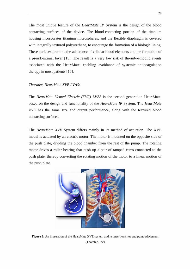
Thoratec, HeartMate XVE LVAS:
The HeartMate Vented Electric (XVE) LVAS is the second generation HeartMate,
based on the design and functionality of the HeartMate IP System. The HeartMate
XVE has the same size and output performance, along with the textured blood
contacting surfaces.
The HeartMate XVE System differs mainly in its method of actuation. The XVE
model is actuated by an electric motor. The motor is mounted on the opposite side of
the push plate, dividing the blood chamber from the rest of the pump. The rotating
motor drives a roller bearing that push up a pair of ramped cams connected to the
push plate, thereby converting the rotating motion of the motor to a linear motion of
the push plate.
Figure 8: An illustration of the HeartMate XVE system and its insertion sites and pump placement
(Thoratec, Inc)

30
The HeartMate XVE System allows for a greater patient mobility than its predecessor,
the HeartMate IP System, since it can be connected to a portable battery pack. As a
result, patients do not have to remain hospitalized throughout their time of VAD
support. Consequently, the HeartMate XVE System is the first system to gain FDA
approval for use as a destination-therapy / alternative-to-transplant pump. However,
even though mobility has been greatly improved the risk of infection still remain as
the system still require transcutaneous wires to power the motor and a venting tube to
allow for displacement of air when the push plate moves back and forth throughout
the pumping cycle.
Abiomed, BVS5000:
The BVS5000 system is an extracorporeal device marketed my Abiomed (Danvers,
Ma). The BVS5000 system was the first device to be approved by the FDA for support
of postcardiotomy patients, making it the second most common cardiac assist system,
following the Intra Aortic Balloon Pump, for support of patients with postcardiotomy
ventricular dysfunction.
The BVS5000 system is intended for short term use, typically 7-10 days, and can be
used for right, left, or bi-ventricular support. The system consists of three principle
components; transthoracic cannulae, a disposable external pump, and a pneumatic
drive module.
Figure 9: The principle of insertion, the disposable pump, and the BVS5000 pneumatic drive module
(Abiomed, Inc)
The disposable pump is a dual-chamber pump contained in a hard polycarbonate
housing. Each chamber contains a flexible polyurethane bladder with a 100-ml

31
volume. A polyurethane trileaflet valve separates the chambers from each other. A
second valve is placed between the ejection chamber and the outlet. By gravity, the
flexible upper chamber fills passively with blood from the atrium, and acts as a
passive reservoir for the lower flexible ejection chamber. The pump’s ejection
chamber is subjected to an alternating positive drive pressure and atmospheric
pressure, allowing it to eject and fill respectively.
Due to the passive filling of the pump, the pump height relative the patient’s atrium is
of great importance. Typical height is approximately 25 cm below the patient’s atria.
Peristaltic pumps The peristaltic pump is constructed as a series of chambers. Currently no peristaltic
pump is approved for clinical use. Akutsu [17], describes in detail a six chamber
peristaltic pump. He describes the pumping mechanism as that of the worm-like
movement of the intestine, squeezing the liquid from chamber to chamber.
Figure 10: Principle of the Peristaltic pump. Shown here is a seven-chamber peristaltic pump. A
squeezing motion pushes the blood forward, as time goes from P1 to P4 (M Stenberg)
Before pumping, the first and last chambers close as air is injected in the balloon that
serves as a wall in the chamber. In the next phase pumping starts by closing the
second chamber at the same time as the last one opens. As the third chamber closes,
the first one opens and so forth, creating a squeezing motion pushing the liquid
forward.
32
The peristaltic pump has one very positive feature in the sense that it fills up at the
same time as it is pumping. There is no separate fill up and ejection phase, enabling
minimal time loss in between cycles. However the peristaltic pump is limited in terms
of maximum output and some regurgitation have been known to occur at the first and
last chamber [17].
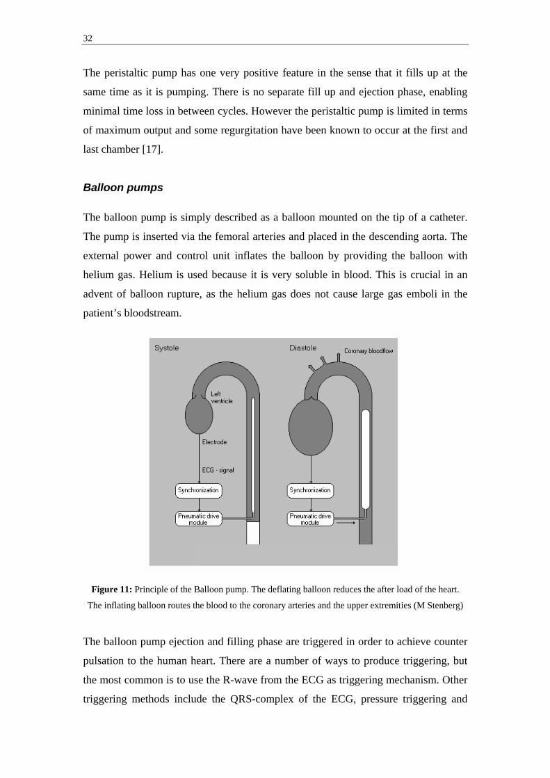
Balloon pumps The balloon pump is simply described as a balloon mounted on the tip of a catheter.
The pump is inserted via the femoral arteries and placed in the descending aorta. The
external power and control unit inflates the balloon by providing the balloon with
helium gas. Helium is used because it is very soluble in blood. This is crucial in an
advent of balloon rupture, as the helium gas does not cause large gas emboli in the
patient’s bloodstream.
Figure 11: Principle of the Balloon pump. The deflating balloon reduces the after load of the heart.
The inflating balloon routes the blood to the coronary arteries and the upper extremities (M Stenberg)
The balloon pump ejection and filling phase are triggered in order to achieve counter
pulsation to the human heart. There are a number of ways to produce triggering, but
the most common is to use the R-wave from the ECG as triggering mechanism. Other
triggering methods include the QRS-complex of the ECG, pressure triggering and
33
controlled pacing [12]. The balloon is triggered to deflate just before the systolic
phase of the heart and then to inflate during the diastolic phase.
The balloon pump does not actually produce any pumping of the blood itself. Instead,
according to Broome’ [18], it works in assisting the heart in two different ways:
1. The inflating balloon routes the blood to the coronary arteries and the upper
extremities during diastole, producing higher myocardial blood flow.
2. The deflating balloon reduces the after load, assisting the ventricle in ejecting
blood to the aorta during systole, thus reducing myocardial oxygen consumption.
The balloon pump does not do any volume work itself but assists the heart in reducing
the after load as mentioned above. This limits the use of the balloon pump since large
volume work assistance is often needed in patients with severe cardiac failure.
However the balloon pump is a relatively cost effective option and is very
advantageous in the low invasive manner of which it is inserted.
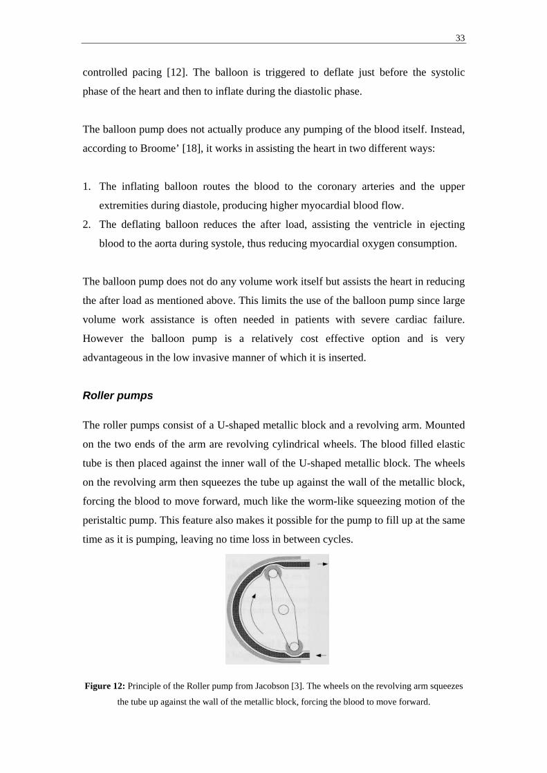
Roller pumps The roller pumps consist of a U-shaped metallic block and a revolving arm. Mounted
on the two ends of the arm are revolving cylindrical wheels. The blood filled elastic
tube is then placed against the inner wall of the U-shaped metallic block. The wheels
on the revolving arm then squeezes the tube up against the wall of the metallic block,
forcing the blood to move forward, much like the worm-like squeezing motion of the
peristaltic pump. This feature also makes it possible for the pump to fill up at the same
time as it is pumping, leaving no time loss in between cycles.
Figure 12: Principle of the Roller pump from Jacobson [3]. The wheels on the revolving arm squeezes
the tube up against the wall of the metallic block, forcing the blood to move forward.

34
Roller pumps are most often used as the pumping source in heart-lung machines and
are not marketed as VADs today.
3.1.2. Radial-flow pumps Radial-flow pumps impart momentum to a fluid, most often by placing a rotating
device in the fluid. Fluid is entered axially through an inlet onto a rotating impeller,
blades, or concentric cones. The rotating device inflicts a rotating motion on the fluid,
accelerates it through the pump, producing a non-pulsating inflow and outflow.
Radial-flow pumps can provide high flow rates at low pressures. However, they are
highly sensitive to changing in and outflow pressures, resulting in an inability to
maintain a precise output under changing in and outflow conditions. Two different
embodiments of the radial-flow pump technology are currently used clinically,
Centrifugal (Vortex) pumps and Rotary (Impeller) pumps.
Centrifugal pumps The Centrifugal pump inflicts angular acceleration on the local fluid, which creates a
centrifugal force on the fluid, and hence flow. The pump is very easy to use since the
output of the pump is directly related to the speed of rotation and to the pressure it is
working against. The technology used is relatively simple and the rotary motor
powering the pump is reusable, making the centrifugal pump very cost-effective.
Medtronic-BioMedicus Biopump®:
The most well known centrifugal pump on the market today is the BioMedicus
Biopump® Centrifugal Pump, marketed by Medtronic-BioMedicus, Inc (Eden Prairie,
USA). The Biopump® was originally developed for cardiopulmonary bypass, but can
be used for uni-ventricular or bi-ventricular circulatory support beyond the surgical
setting. The pump can rotate up to 5000 revolutions per minute (rpm) and can provide
flows of up to 8 l / min.
35
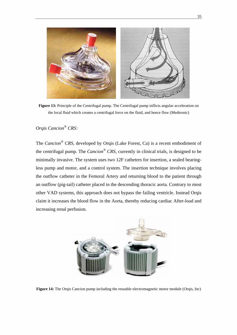
Figure 13: Principle of the Centrifugal pump. The Centrifugal pump inflicts angular acceleration on
the local fluid which creates a centrifugal force on the fluid, and hence flow (Medtronic)
Orqis Cancion® CRS:
The Cancion® CRS, developed by Orqis (Lake Forest, Ca) is a recent embodiment of
the centrifugal pump. The Cancion® CRS, currently in clinical trials, is designed to be
minimally invasive. The system uses two 12F catheters for insertion, a sealed bearing-
less pump and motor, and a control system. The insertion technique involves placing
the outflow catheter in the Femoral Artery and returning blood to the patient through
an outflow (pig-tail) catheter placed in the descending thoracic aorta. Contrary to most
other VAD systems, this approach does not bypass the failing ventricle. Instead Orqis
claim it increases the blood flow in the Aorta, thereby reducing cardiac After-load and
increasing renal perfusion.
Figure 14: The Orqis Cancion pump including the reusable electromagnetic motor module (Orqis, Inc)
36
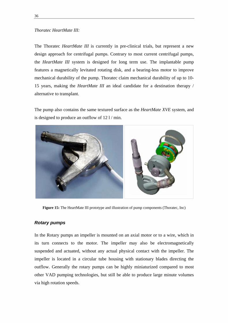
Thoratec HeartMate III:
The Thoratec HeartMate III is currently in pre-clinical trials, but represent a new
design approach for centrifugal pumps. Contrary to most current centrifugal pumps,
the HeartMate III system is designed for long term use. The implantable pump
features a magnetically levitated rotating disk, and a bearing-less motor to improve
mechanical durability of the pump. Thoratec claim mechanical durability of up to 10-
15 years, making the HeartMate III an ideal candidate for a destination therapy /
alternative to transplant.
The pump also contains the same textured surface as the HeartMate XVE system, and
is designed to produce an outflow of 12 l / min.
Figure 15: The HeartMate III prototype and illustration of pump components (Thoratec, Inc)
Rotary pumps In the Rotary pumps an impeller is mounted on an axial motor or to a wire, which in
its turn connects to the motor. The impeller may also be electromagnetically
suspended and actuated, without any actual physical contact with the impeller. The
impeller is located in a circular tube housing with stationary blades directing the
outflow. Generally the rotary pumps can be highly miniaturized compared to most
other VAD pumping technologies, but still be able to produce large minute volumes
via high rotation speeds.
37
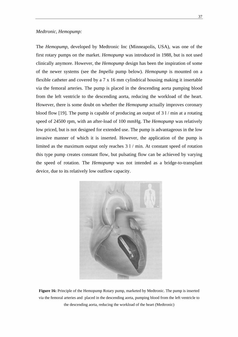
Medtronic, Hemopump:
The Hemopump, developed by Medtronic Inc (Minneapolis, USA), was one of the
first rotary pumps on the market. Hemopump was introduced in 1988, but is not used
clinically anymore. However, the Hemopump design has been the inspiration of some
of the newer systems (see the Impella pump below). Hemopump is mounted on a
flexible catheter and covered by a 7 x 16 mm cylindrical housing making it insertable
via the femoral arteries. The pump is placed in the descending aorta pumping blood
from the left ventricle to the descending aorta, reducing the workload of the heart.
However, there is some doubt on whether the Hemopump actually improves coronary
blood flow [19]. The pump is capable of producing an output of 3 l / min at a rotating
speed of 24500 rpm, with an after-load of 100 mmHg. The Hemopump was relatively
low priced, but is not designed for extended use. The pump is advantageous in the low
invasive manner of which it is inserted. However, the application of the pump is
limited as the maximum output only reaches 3 l / min. At constant speed of rotation
this type pump creates constant flow, but pulsating flow can be achieved by varying
the speed of rotation. The Hemopump was not intended as a bridge-to-transplant
device, due to its relatively low outflow capacity.
Figure 16: Principle of the Hemopump Rotary pump, marketed by Medtronic. The pump is inserted
via the femoral arteries and placed in the descending aorta, pumping blood from the left ventricle to
the descending aorta, reducing the workload of the heart (Medtronic)

38
Impella Cardiosystems, Impella pumps:
Impella Cardiosystems (Aachen, Germany), acquired by Abiomed (Danvers, Ma) in
April 2005, is developing several pump versions of the Impella pump, in which an
electric motor, actuating an impeller, with a diameter of 6,4 mm is mounted on a
catheter. The distal end of the motor is placed in the ventricle, and the proximal outlet
end of the motor is placed in the ascending aorta (Fig17).
Figure 17: The Impella Recover 2.5 / 5.0 pump and principle of insertion (Impella Cardiosystems)
The Recover LP 2.5 pump is a minimally invasive ventricular unloading version,
which is inserted percutaneously via the femoral artery. Up to 2,5 l / min can be
delivered by the pump from the left ventricle into the ascending aorta. The Recover
LP 2.5 can be implanted for up to 5 days.
The Recover LP 5.0 provides enhanced hemodynamic support, up to 5,0 l / min. The
Recover LP 5.0 is a minimally invasive ventricular unloading catheter, which is
placed via a femoral artery cut-down. Up to 5 l / min can be delivered from the left
ventricle into the ascending aorta. Can be implanted for up to 7 days.
The Recover RD and LD versions are intended to provide patients suffering from
reduced cardiac output with right/left or bi-ventricular support. The pumps are
capable of delivering a total of up to 6 and 5 l / min, respectively. The Recover RD
Direction of blood flow
Pump Blood outlet Blood inlet

39
and LD versions require surgical insertion, and are anastomosed directly to the heart
and greater vessels.
Micromedtech, DeBakey pump:
The DeBakey pump developed by Micromed (Austin, Texas) along with the Jarvik
2000 FlowMaker below, represent the new generation of impeller based pumps. An
impeller sitting axially in the flow stream propels the blood through the pump that
consequently produces a constant inflow and constant outflow. The DeBakey Pump
includes the titanium pump and inlet cannulae, a percutaneous power cable, a flow
probe, and an outflow graft (Fig18).
The impeller is the only moving part of the pump. It has six blades with eight magnets
hermetically sealed in each blade. The impeller spins at 7500-12500 rpm producing
flows of up to 10 l / min. The components are all enclosed in the hermetically sealed
titanium flow tube. Actuation is generated by a brush-less DC motor stator that is
contained in the stator housing. The pump is attached to a titanium inlet cannulae that
is placed into the left ventricular apex. A graft is connected to the pump outlet and
anastomosed to the ascending aorta.
Figure 18: Cross section of the DeBakey pump and principle of insertion (Micromedtech, Inc)
40
Jarvik Heart, Jarvik 2000 FlowMaker:
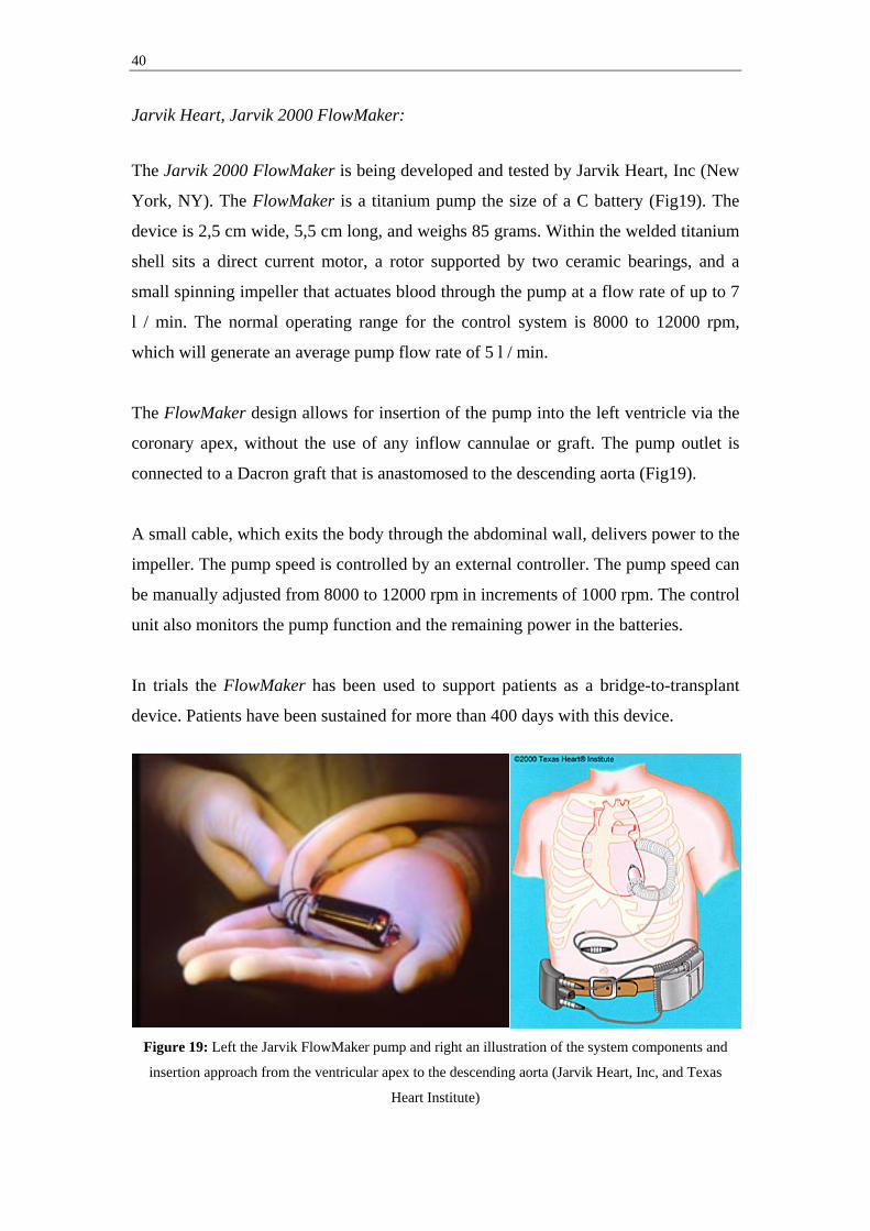
The Jarvik 2000 FlowMaker is being developed and tested by Jarvik Heart, Inc (New
York, NY). The FlowMaker is a titanium pump the size of a C battery (Fig19). The
device is 2,5 cm wide, 5,5 cm long, and weighs 85 grams. Within the welded titanium
shell sits a direct current motor, a rotor supported by two ceramic bearings, and a
small spinning impeller that actuates blood through the pump at a flow rate of up to 7
l / min. The normal operating range for the control system is 8000 to 12000 rpm,
which will generate an average pump flow rate of 5 l / min.
The FlowMaker design allows for insertion of the pump into the left ventricle via the
coronary apex, without the use of any inflow cannulae or graft. The pump outlet is
connected to a Dacron graft that is anastomosed to the descending aorta (Fig19).
A small cable, which exits the body through the abdominal wall, delivers power to the
impeller. The pump speed is controlled by an external controller. The pump speed can
be manually adjusted from 8000 to 12000 rpm in increments of 1000 rpm. The control
unit also monitors the pump function and the remaining power in the batteries.
In trials the FlowMaker has been used to support patients as a bridge-to-transplant
device. Patients have been sustained for more than 400 days with this device.
Figure 19: Left the Jarvik FlowMaker pump and right an illustration of the system components and
insertion approach from the ventricular apex to the descending aorta (Jarvik Heart, Inc, and Texas
Heart Institute)
41
3.2. Therapeutic objective
As congenital and reversible heart decease is two very different situations, the
therapeutic needs also differ. We may need to assist the heart in different ways to
achieve our objectives. This may mean using different techniques to reduce after-load
and / or myocardial oxygen consumption. Two different ways of assisting the heart
are identified, Series-type ventricular assist and Bypass-type ventricular assist. These
are extensively discussed by Akutsu [17].
3.2.1. Series-type ventricular assist
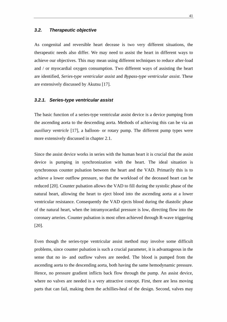
The basic function of a series-type ventricular assist device is a device pumping from
the ascending aorta to the descending aorta. Methods of achieving this can be via an
auxiliary ventricle [17], a balloon- or rotary pump. The different pump types were
more extensively discussed in chapter 2.1.
Since the assist device works in series with the human heart it is crucial that the assist
device is pumping in synchronization with the heart. The ideal situation is
synchronous counter pulsation between the heart and the VAD. Primarily this is to
achieve a lower outflow pressure, so that the workload of the deceased heart can be
reduced [20]. Counter pulsation allows the VAD to fill during the systolic phase of the
natural heart, allowing the heart to eject blood into the ascending aorta at a lower
ventricular resistance. Consequently the VAD ejects blood during the diastolic phase
of the natural heart, when the intramyocardial pressure is low, directing flow into the
coronary arteries. Counter pulsation is most often achieved through R-wave triggering
[20].
Even though the series-type ventricular assist method may involve some difficult
problems, since counter pulsation is such a crucial parameter, it is advantageous in the
sense that no in- and outflow valves are needed. The blood is pumped from the
ascending aorta to the descending aorta, both having the same hemodynamic pressure.
Hence, no pressure gradient inflicts back flow through the pump. An assist device,
where no valves are needed is a very attractive concept. First, there are less moving
parts that can fail, making them the achillies-heal of the design. Second, valves may
42
cause hemolysis and induce thrombosis, reducing the maximum time patients can be
on the VAD.
Figure 20: General principle of Series-type ventricular assist. The basic function of a series-type
ventricular assist device is a device pumping from the ascending aorta to the descending aorta. Methods
of achieving this can be via an auxiliary ventricle, as shown here, a balloon- or rotary pump (M
Stenberg).
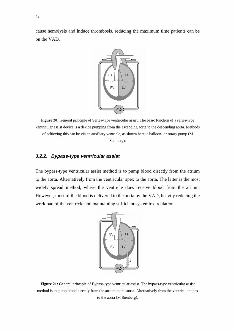
3.2.2. Bypass-type ventricular assist
The bypass-type ventricular assist method is to pump blood directly from the atrium
to the aorta. Alternatively from the ventricular apex to the aorta. The latter is the most
widely spread method, where the ventricle does receive blood from the atrium.
However, most of the blood is delivered to the aorta by the VAD, heavily reducing the
workload of the ventricle and maintaining sufficient systemic circulation.
Figure 21: General principle of Bypass-type ventricular assist. The bypass-type ventricular assist
method is to pump blood directly from the atrium to the aorta. Alternatively from the ventricular apex
to the aorta (M Stenberg).

43
Since the VAD works parallel to the heart and almost all of the blood is pumped by
the VAD, it is not crucial that the VAD works in synchronous counter pulsation with
the heart. However, clinical reports does recommend the VAD to pump out of phase
to the heart, [17]. Since the outflow pressure (aortic pressure) is directly related to the
flow from the hearts ventricle and the bypass-type assist device, the outflow pressure
is often higher when the assist device is on (Fig22), forcing the natural ventricle to
work against the higher pressure induced by the assist device. By counter pulsation
we allow the VAD to fill during the systolic phase of the natural heart, allowing the
natural heart to eject blood into the ascending aorta at a lower ventricular resistance.
Figure 22: The effect of Aortic pressure when the assist device is off, run in synchronous counter
pulsation and in asynchronous full-to-empty mode by Farrar [20]. Presentation modified to fit the
format of this report.
This method does, however, pump from a low pressure area to a high pressure area,
resulting in working against a positive pressure gradient. To prevent back flow
through the pump, in- and outlet valves are needed. This makes it crucial for the VAD
to be operational at all times, since stagnant flow will produce thrombosis [17].
Rotary pumps can, however, also be used as a bypass-type ventricular assist devise.
One example is the Jarvik 2000 FlowMaker marketed by Jarvik Heart, Inc. In this
case the need for in- and outlet valves are eliminated since the continuous flow
produced can be made higher than the back flow induced by the pressure gradient
between aorta and atrium / apex.
44
3.3. Output characteristics
Subdivision of the different VAD designs can also be made into groups on account of
their outflow characteristics, i.e. pulsating outflow or non- pulsating outflow.
Generally the displacement pumps generate a pulsating outflow, while the radial-flow
pumps generate a non- pulsating outflow. However, by continuously changing the
speed of rotation between two different rpm, most rotary and centrifugal can be made
to produce a pulsating outflow, even though this approach is generally not used
clinically. At low to medium rpm in combination with some residual cardiac function
of the native heart, even patients with rotary and centrifugal pumps will have a slight
pulse. However, if the pump speed is turned up and the residual pumping function is
weak, the patient pulse will eventually become non-detectable.
3.3.1. Pulsating outflow
The first pumps to be employed in larger scale as ventricular assist devices have been
displacement type pumps, with pulsating inflow as well as outflow. For that reason
pulsating outflow pumps rest on decades of clinical experience. Also, the REMATCH
trial was based on the use of the HeartMate VAD system, a pulsating outflow pump.
Pulsating flow pumps does, however have a potential advantage over continuous flow
pumps because of the advantages in synchronous counter pulsation. Studies by Platt
and colleagues [21], have shown that this technique of synchronous counter pulsation
is in fact the most beneficial when it comes to improving myocardial oxygen
consumption as well as cardiac output.
Various continuous flow pump developers have suggested running their pumps at a
varying rpm to produce pulsating flow. However, some concern was brought to
attention on whether altering the rpm of dynamic pumps, in order to produce pulsating
flow, would result in added hemolysis. A recent study has, however, shown that no
added hemolysis took place while periodically altering rpm in centrifugal pumps [22].

45
3.3.2. Continuous / Non-pulsating outflow
The continuous, or Non-pulsating, outflow pumps are generally smaller than
displacement pumps with the same output capacity, and they require no volume
compliance chambers, making them ideal for total implantation. The use of non-
pulsating assist devices are widely used in acute situations and for short-term cardiac
assist. Non-pulsating pumps are also advantageous during cardiopulmonary bypass,
while operating on the heart.
A number of reports indicate that use of non-pulsating pumps may result in
deterioration of organ function and inflict morphologic changes in the aorta. This is
supported by Krafte-Jacobs [23], Konishi and colleagues [24], as well as Nishimura
and colleagues [25]. However, the effects of long-term continuous, or Non-pulsating,
cardiac assist is currently unknown.

46
4. Current Ventricular Assist Devices A number of VAD systems are commercially available or in late stage development /
trials. This chapter aims to provide a general overview of these systems, their
approved use, general strengths and shortcomings.
From a regulatory perspective, current VAD systems are divided into three separate
groups, based upon intended use (Table2); bridge-to-recovery (BTR), bridge-to-
transplant (BTT), destination therapy (DT):
Company Product FDA approval CE mark Ongoing trial
AbioMed BVS 5000 BTR BTR No
AbioMed AB 5000 BTR BTR No
AbioMed AbioCore No No Yes (DT – US)
Arrow
International
Intra-Aortic
Balloon Pump
BTR BTR No
Arrow
International
CorAide No No Yes (BTT – US)
Arrow
International*
LionHeart No DT Yes
Berlin Heart Excor
(several sizes)
No BTT No
Berlin Heart Incor No BTR, BTT No
DataScope CS100 / System
98XT
BTR BTR No
Impella
CardioSystems**
Impella Recover
LP 2,5 & LP 5,0
No BTR Yes (BTR – US
for LP 5,0)
Impella
CardioSystems**
Impella Recover
Biventricular
system (LD 2,5
+ RD 5,0)
No BTR Yes (BTR – US
for LD 2,5)
Jarvik Heart Jarvik 2000
FlowMaker
No BTT, DT Yes (BTT – US)
Medtronic BioPump BTR, BTT BTR, BTT No

47
(Two sizes)
MicroMed DeBakey VAD Pediatric BTR BTT, DT Yes (DT, BTT –
US)
Terumo DuraHeart No No Yes (BTT – EU)
Thoratec Thoratec VAD BTR, BTT BTR, BTT No
Thoratec Thoratec IVAD BTR, BTT BTR, BTT No
Thoratec HeartMate IP
LVAS
BTT BTT No
Thoratec HeartMate XVE
LVAS
BTT, DT BTT, DT No
Thoratec HeartMate II No No Yes (BTT – US,
DT – EU)
Thoratec HeartMate III No No Pre-clinical
Ventracor VentrAssist No No Yes
WorldHeart Novacor BTT BTR, BTT, DT Yes (DT - US)
WorldHeart Next Generation
LVAS
No No Pre-clinical
WorldHeart HeartQuest
VAD
No No Pre-clinical
* Sales discontinued in 2005 ** Acquisition by Abiomed underway *** Through acquisition of MedQuest Table 2: Overview of the regulatory status of current VAD systems, as of April 05, 2005 (M Stenberg) 4.1. Advantages / disadvantages of Currently FDA approved VAD
systems
Currently, a total of 10 VAD systems have FDA regulatory approval for adult clinical
use in the US and are used on a regular basis. Some of these systems have been in
clinical use for well over 10 years, whereas some have just recently gained regulatory
approval.
Most current systems in clinical use are displacement type VAD systems, with their
relative large size being their greatest disadvantage. For the implantable versions this
is disqualifying most children and women from support. To date, the smallest
48
approved implantable VAD system require a BMI of 1,5 m2 for implantation.
However, the external displacement pumps allow for support of smaller sized patients.
In addition, all currently approved implantable displacement type VAD systems
require a venting line (or compliance chamber) to allow for the pump internal volume
displacement.
Also, apart from the transcutaneous venting lines used by some products, all current
external as well as internal VAD systems require either transcutaneous
cannulae/catheters, or transcutaneous pneumatic or electric leads, respectively. This
constitutes a second very serious issue of the current VAD systems, namely the risk of
infection associated with transcutaneous connections. Reports by Pennington and
colleagues [26] and Murakami and colleagues [27], show that between 20% and 55%
of the patients receiving VAD support also receive transcutaneous drive line related
infections.
Certain displacement pumps also suffer from the fact that parts of the blood sac
sometimes does not stay in constant contact with blood, resulting in the build up of
thrombus. As these buildups are washed off by the blood flow they cause potentially
lethal emboli. The need for a consistent washing of all blood contacting surfaces is
recognized by Farrar and colleagues [28], and in the Thoratec Laboratories Corp,
Directions for use [29]. To avoid the risk of thrombosis formation, the use of
anticoagulation agents such as Heparin and Warfarin is recommended for the
Thoratec VAD system [29]. However, no thrombosis formation has been reported in
the HeartMate blood interfacing compartment. The compartment surface is textured
polyurethane, which induces formation of a fibrin-cellular coagulum [6], at initial
blood contact. The thrombus that later form is then fixed to the surface by fibrin
deposition.
All currently approved VAD systems also require highly invasive procedures for
insertion and removal. This is inevitable for the group of systems that are intended for
long term use, or high volume support. However, the systems currently used for short
to intermediate term use, typically with a bridge-to-recovery objective, also require
cannulae and consequently a sternotomy for insertion.
49
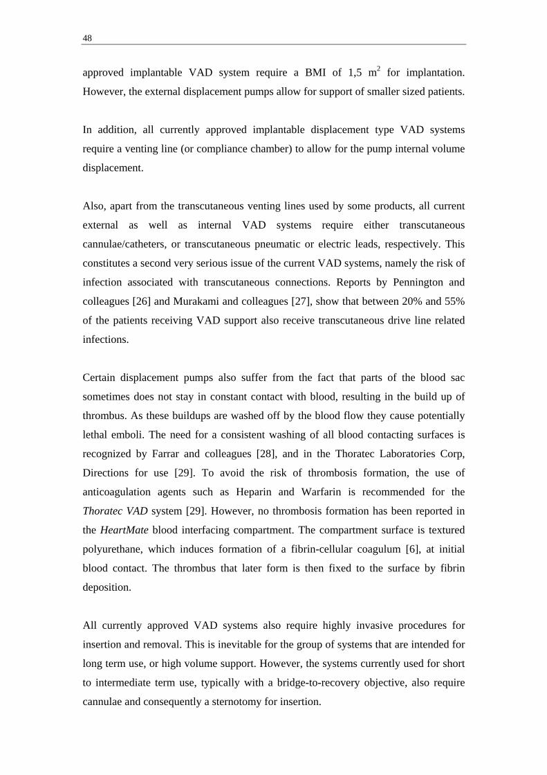
The following VAD system profiles provide a more detailed overview of the general
advantages and disadvantages of selected VAD systems currently FDA approved for
adult use:
Manufacturer Product Advantages / Disadvantages
AbioMed BVS 5000 + Multiple ventricle support
Technology: Displacement + Cost effective
Output: 5 l / min (100ml stroke) + Allows for variety of patient sizes
Placement: External - Very limited patient mobility
Support type: LVAD/RVAD/BIVAD - Short term use only
Duration: Short - Invasive insertion (cannulae anastomosed
Actuation: Pneumatic directly to heart / arteries)
Ambulation: No - Transcutaneous cannulae
FDA status: BTR
CE status: BTR
Manufacturer Product Advantages / Disadvantages
Abiomed AB 5000 + Multiple ventricle support
Technology: Displacement + Allows for relatively long term use
Output: 6 l / min (100ml stroke) - Discomfort due to external pump
Placement: External - Some mobility restrictions
Support type: LVAD/RVAD/BIVAD - Invasive insertion (cannulae anastomosed
Duration: Intermediate (months) directly to heart / arteries)
Actuation: Pneumatic - Transcutaneous cannulae
Ambulation: Fair - Shorter transportation
FDA status: BTR
CE status: BTR
50
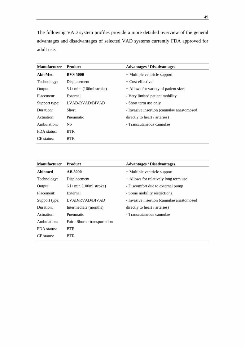
Manufacturer Product Advantages / Disadvantages
Arrow Int. Intra-Aortic Balloon Pump + No size considerations
Technology: Displacement + Minimal invasive insertion (Femoral
Output: N/A (increases coronary perfusion) catheterization)
Placement: Internal + Increases intramyocardial perfusion
Support type: N/A - Does not increase systemic perfusion
Duration: Short (days) - Short term use only
Actuation: Pneumatic - Very limited patient mobility
Ambulation: No
FDA status: BTR
CE status: BTR
Manufacturer Product Advantages / Disadvantages
DataScope CS100 / System 98XT + No size considerations
Technology: Displacement + Minimal invasive insertion (Femoral
Output: N/A (increases coronary perfusion) catheterization)
Placement: Internal + Increases intramyocardial perfusion
Support type: N/A - Does not increase systemic perfusion
Duration: Short (days) - Short term use only
Actuation: Pneumatic - Very limited patient mobility
Ambulation: No
FDA status: BTR
CE status: BTR
Manufacturer Product Advantages / Disadvantages
Medtronic Biopump (80ml & 48ml) + Multiple ventricle support
Technology: Radial flow + Cost effective
Output: 10 l / min (80ml version) + 48ml version allows for pediatric use
Placement: External - Short term use only
Support type: LVAD/RVAD/BIVAD - Very limited patient mobility
Duration: Short (<5 days) - Invasive insertion (cannulae anastomosed
Actuation: Electric directly to heart / arteries)
Ambulation: No - Transcutaneouos cannulae
FDA status: BTR/BTT
CE status: BTR/BTT

51
Manufacturer Product Advantages / Disadvantages
Thoratec Thoratec VAD + Multiple ventricle support
Technology: Displacement + Allows for use in patients >17 kg
Output: 1,3 – 7,2 l / min (65ml stroke) + Allows for relatively long term use
Placement: External - Discomfort due to external pump
Support type: LVAD/RVAD/BIVAD - Some mobility restrictions
Duration: Intermediate (months) - Invasive insertion (cannulae anastomosed
Actuation: Pneumatic directly to heart / arteries)
Ambulation: Fair (with TLC-II Portable VAD driver) - Transcutaneous cannulae
FDA status: BTR/BTT
CE status: BTR/BTT
Manufacturer Product Advantages / Disadvantages
Thoratec Thoratec IVAD + Multiple ventricle support
Technology: Displacement + Small compared to other implantable pulsating
Output: 1,3 – 7,2 l / min (65ml stroke) pumps
Placement: Internal + Allows for long term use
Support type: LVAD/RVAD/BIVAD + Decreased patient discomfort due to
Duration: Intermediate/long (months/years) implantable pump (compare Thoratec VAD)
Actuation: Pneumatic - Some mobility restrictions
Ambulation: Fair (with TLC-II Portable VAD driver) - Invasive insertion (cannulae
FDA status: BTR/BTT anastomosed directly to heart / arteries)
CE status: BTR/BTT - Transcutaneous cannulae
Manufacturer Product Advantages / Disadvantages
Thoratec HeartMate XVE LVAS + Implantable
Technology: Displacement + Long term use
Output: 11 l / min (85ml stroke) + Discharge possible (8h battery life)
Placement: Internal + Can be used for DT purposes
Support type: LVAD + Superior coating to prevent thrombus
Duration: Long (years) - Large sized, excluding patients <1,5 m2 BSA
Actuation: Electric - Patient discomfort due to heavy weight (1150g)
Ambulation: Good - Discharge possible - Invasive insertion (cannulae anastomosed
FDA status: BTT/DT directly to heart / arteries)
CE status: BTT/DT - Transcutaneous power leads and venting tube

52
Manufacturer Product Advantages / Disadvantages
Thoratec HeartMate IP LVAS + Implantable
Technology: Displacement + Long term use
Output: 11 l / min (85ml stroke) + Fair patient mobility
Placement: Internal + Superior coating to prevent thrombus
Support type: LVAD - Large sized, excluding many patients
Duration: Long (years) - Patient discomfort due to heavy weight
Actuation: Pneumatic - Invasive insertion (cannulae anastomosed
Ambulation: Fair directly to heart / arteries)
FDA status: BTT - Transcutaneous cannulae
CE status: BTT
Manufacturer Product Advantages / Disadvantages
World Heart Novacor + Implantable
Technology: Displacement + Long term use
Output: 10 l / min + Discharge possible
Placement: Internal + Can be used for DT purposes (EU)
Support type: LVAD - Large sized, excluding patients <1,5 m2 BSA
Duration: Long (years) - Invasive insertion (cannulae anastomosed
Actuation: Electric directly to heart / arteries)
Ambulation: Good - Discharge possible - Transcutaneous power leads and venting tube
FDA status: BTT
CE status: BTR/BTT/DT
4.2. Advantages / disadvantages of future VAD systems
As a result of the currently unmet technical and clinical needs discussed above, a
number of novel VAD systems are currently under development with the objective of
addressing the shortcomings of the currently approved systems. Three general design
trends can be identified for these future VAD systems; Miniaturization, Alternative
insertion, and Fully implantable systems. Although currently not approved for clinical
use in the US, some of these systems enjoy regulatory approval in the EU (Table2).
Miniaturization has been key in most ongoing VAD development projects. Since there
is a limit to how far miniaturization can go for displacement based pumps, many

53
newer pumps employ radial flow technologies. This has allowed certain VAD
systems, such as the DeBakey pump to reduce the size of the pump down to the size of
an A battery, allowing for implantation even in pediatric patients (BSA ≥ 0,7 m2).
The employment of radial flow technologies and novel miniaturized motors have also
allowed for alternative insertion techniques. The Impella pump is a modern
embodiment of the Hemopump, and a good example of how miniaturized motors can
be employed on small sized catheters along with the actual blood contacting impeller.
The constant filling of these pumps, which allows longer time for filling and thereby
lower filling rates than that of displacement pumps, has also facilitated the use of
minimally invasive catheter based VAD systems, such as the Impella and Orqis
Cancion CRS systems. However, minimally invasive Femoral or Axillary
catheterization does put a definite limit on the size of catheters to be used. This
restricts the maximum output these systems can provide. For short to intermediate
term support, mainly in bridge to recovery settings, the level of output that these
systems can provide may be sufficient.
A clear development trend is also the increased efforts of achieving fully implantable
VAD systems. This involves integration of as much as possible of the VAD system
components, addressing the need or eliminating the need for volume displacement,
and providing implantable power sources and controllers that can be recharged and
reprogrammed, respectively, transcutaneously. Arrow currently has a fully
implantable system for clinical use with its LionHeart system (Fig23).
Figure 23: Illustration of the LionHeart VAD system, including compliance chamber (Arrow
International)

54
World Heart, and Thoratec both have fully implantable systems in development for
their Next Generation LVAS, and HeartMate II systems. The LionHeart system is
currently approved for use in the EU for DT applications, but has recently been
discontinued from sale. However, the LionHeart system is a displacement pump and
requires an implantable compliance chamber, a component that requires changing on
a regular basis. The Next Generation LVAS system will use a dual chamber system
that eliminates pump external displacement and thereby the need for a compliance
chamber.
Among the next generation VAD systems there are some displacement based pumps,
although most pumps are employing different radial-flow technologies. The
developers of these radial flow based pumps argue several potential advantages over
pulsating flow (displacement) pumps [30]; 1) They are smaller devices and can be
used in smaller patients (BSA < 1,5), 2) they have fewer moving parts then
displacement pumps, and thus may be less prone to mechanical failures, although
there is no current data to support this claim, 3) They do not require a compliance
chamber system because of their continuous flow, 4) Generally they have lower
energy requirements compared to displacement pumps, and 5) The smaller size of the
device and pocket may decrease the risk of infection, although there is no current data
to support this claim.
However, these radial flow based devices also have potential disadvantages compared
to displacement pumps [30]; 1) Most of the current axial flow pumps in development /
trials employ bearings lubricated by blood, which elevates the risk of in-situ thrombus
and thromboemboli, 2) Chronic anticoagulation is necessary, 3) Some degree of
hemolysis is common, and the long term effects of this is currently unknown, 4) The
long term effect of continuous flow is currently unknown, and 5) Feedback systems
for controlling pump speed are complex and currently clinically unproven.
The following VAD system profiles provide a more detailed overview of the general
advantages and disadvantages of selected VAD systems currently in development /
trials. Much of the information on pump characteristics presented below represent
company objectives. Much of this information is not yet verified or subject to
verification in ongoing trials.

55
Manufacturer Product Advantages / Disadvantages
Abiomed Abiocor + The only total artificial heart system
Technology: Displacement + Synchronized control of both ventricles
Output: No information + Requires no transcutaneous leads
Placement: Internal (removal of heart) + No need for volume compliance chamber
Support type: Total Artificial Heart (TAH) - Large sized
Duration: Long (years) - Requires advanced MRI modeling to determine
Actuation: Electric fit
Ambulation: Good - Highly invasive insertion (incl. removal of
FDA status: Not approved / in trials native heart)
CE status: Not approved
Manufacturer Product Advantages / Disadvantages
Arrow Int. CorAide + Small sized
Technology: Radial-flow (Centrifugal) + Long term use
Output: No information - Requires transcutaneous power leads
Placement: Internal - Invasive insertion
Support type: LVAD - Effects of long term continuos flow unknown
Duration: Long (years)
Actuation: Electric
Ambulation: Good
FDA status: Not approved / in trials
CE status: Not approved
Manufacturer Product Advantages / Disadvantages
Berlin Heart Excor (10 to 80ml versions) + Smaller versions allow for pediatric use
Technology: Displacement + Multiple ventricle support
Output: > 8 l / min (80ml stroke) + Allows for relatively long term use
Placement: External - Discomfort due to external pump
Support type: LVAD/RVAD/BIVAD - Some mobility restrictions
Duration: Intermediate (months) - Invasive insertion
Actuation: Pneumatic - Requires transcutaneous cannulae / leads
Ambulation: Fair (with Mobile Driving System Excor)
FDA status: No
CE status: BTT

56
Manufacturer Product Advantages / Disadvantages
Berlin Heart Incor + Small sized
Technology: Radial-flow (Rotary) + Magnetically suspended impeller
Output: ~ 7 l / min + Long term use
Placement: Internal - Require transcutaneous power leads*
Support type: LVAD - Invasive insertion
Duration: Long (years) - Effects of long term continuos flow unknown
Actuation: Electric
Ambulation: Good
FDA status: No
CE status: BTR, BTT * Fully implantable version under development
Manufacturer Product Advantages / Disadvantages
Impella Recover LP 2,5 & LP 5,0 + Very small system (approximately 15 grams)
Technology: Radial-flow (Rotary) + Minimal invasive insertion (Femoral
Output: 2,5 & 5,0 l / min catheterization using 9F catheters with 12F and
Placement: Internal 21F mounted cannulae
Support type: LVAD + Allows for short transports with small driver
Duration: Short (5 & 7 days) - Short term use only
Actuation: Electric - Requires transcutaneous power leads
Ambulation: Fair - Shorter transportation
FDA status: Not approved / in trials
CE status: BTR
Manufacturer Product Advantages / Disadvantages
Impella Recover LD & RD + Very small BIVAD system (2 x 15 grams)
Technology: Radial-flow (Rotary) + Adequate output (even with its small size)
Output: 5,0 & 6,0 l / min + Allows for short transports with small driver
Placement: Internal - Short term use only
Support type: BIVAD - Invasive insertion relative short support time
Duration: Short (7 days) - Requires transcutaneous power leads
Actuation: Electric
Ambulation: Fair - Shorter transportation
FDA status: Not approved / in trials
CE status: BTR
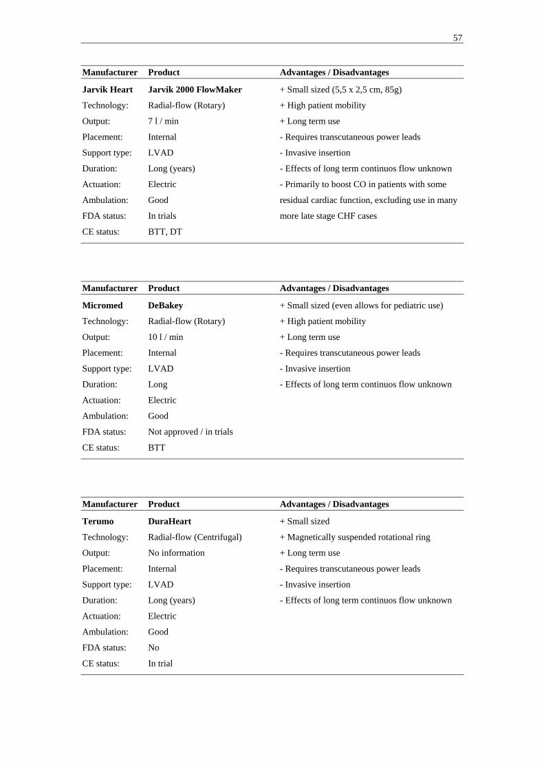
57
Manufacturer Product Advantages / Disadvantages
Jarvik Heart Jarvik 2000 FlowMaker + Small sized (5,5 x 2,5 cm, 85g)
Technology: Radial-flow (Rotary) + High patient mobility
Output: 7 l / min + Long term use
Placement: Internal - Requires transcutaneous power leads
Support type: LVAD - Invasive insertion
Duration: Long (years) - Effects of long term continuos flow unknown
Actuation: Electric - Primarily to boost CO in patients with some
Ambulation: Good residual cardiac function, excluding use in many
FDA status: In trials more late stage CHF cases
CE status: BTT, DT
Manufacturer Product Advantages / Disadvantages
Micromed DeBakey + Small sized (even allows for pediatric use)
Technology: Radial-flow (Rotary) + High patient mobility
Output: 10 l / min + Long term use
Placement: Internal - Requires transcutaneous power leads
Support type: LVAD - Invasive insertion
Duration: Long - Effects of long term continuos flow unknown
Actuation: Electric
Ambulation: Good
FDA status: Not approved / in trials
CE status: BTT
Manufacturer Product Advantages / Disadvantages
Terumo DuraHeart + Small sized
Technology: Radial-flow (Centrifugal) + Magnetically suspended rotational ring
Output: No information + Long term use
Placement: Internal - Requires transcutaneous power leads
Support type: LVAD - Invasive insertion
Duration: Long (years) - Effects of long term continuos flow unknown
Actuation: Electric
Ambulation: Good
FDA status: No
CE status: In trial

58
Manufacturer Product Advantages / Disadvantages
Thoratec HeartMate II + Small sized
Technology: Radial-flow (Rotary) + Long term use
Output: No information - Requires transcutaneous power leads
Placement: Internal - Invasive insertion
Support type: LVAD - Effects of long term continuous flow unknown
Duration: Long (years)
Actuation: Electric
Ambulation: Good
FDA status: In trial
CE status: In trial
Manufacturer Product Advantages / Disadvantages
Thoratec HeartMate III + Small sized
Technology: Radial-flow (Centrifugal) + Bearing-less motor
Output: >12 l / min + Long term use (company claim 10-15 years)
Placement: Internal + Offers the HeartMate textured blood contacting
Support type: LVAD surfaces / coating
Duration: Long (years) - Requires transcutaneous power leads
Actuation: Electric - Invasive insertion
Ambulation: Good - Effects of long term continuous flow unknown
FDA status: Pre-clinical
CE status: Pre-clinical
Manufacturer Product Advantages / Disadvantages
Ventracor VentrAssist + Relatively small sized (60mm in diameter,
Technology: Radial-flow (Centrifugal) 298g)
Output: No information + Hydrodynamically suspended impeller
Placement: Internal + Long term use
Support type: LVAD - Requires transcutaneous power leads
Duration: Long (years) - Invasive insertion
Actuation: Electric - Effects of long term continuous flow unknown
Ambulation: Good
FDA status: Approved to initiate pilot study (BTT)
CE status: In trials

59
Manufacturer Product Advantages / Disadvantages
World Heart Next generation LVAS + Electromagnetic actuation (high durability for a
Technology: Displacement pulsating outflow pump)
Output: No information + The only next generation implantable pulsating
Placement: Internal VAD system
Support type: LVAD/RVAD + No need for a volume compliance chamber
Duration: Long (years) + No transcutaneous leads in final version
Actuation: Electric - Invasive insertion
Ambulation: Good - Larger then most competing long term radial
FDA status: Pre-clinical flow VAD systems
CE status: Pre-clinical
Manufacturer Product Advantages / Disadvantages
World Heart HeartQuest VAD + Small sized
Technology: Radial-flow (Centrifugal) + Magnetically suspended and driven impeller
Output: No information + Long term use
Placement: Internal - Requires transcutaneous power leads
Support type: LVAD - Invasive insertion
Duration: Long (years) - Effects of long term continuous flow unknown
Actuation: Electric
Ambulation: Good
FDA status: Pre-clinical
CE status: Pre-clinical

60
5. The Dynamic Displacement Pump
The concept of Differential Displacement Pumps was first introduced by Dr Stig
Lundbäck [1], as a type of pumps combining the properties of the radial-flow
(dynamic) and displacement pumps, thus duplicating the pumping mechanism of the
human heart. This implies a pump with two chambers, a filling chamber (Atrium) and
an ejection chamber (Ventricle). As in the human heart the filling chamber and the
ejection chamber is divided by a valve (Mitral valve), as is the ejection chamber and
the outlet (Aortic valve). The pumping motion is provided through an oscillating
motion of the Atrio-Ventricular (AV) valve plane enabling a pulsating outflow and
continuos inflow, where the term “continuos inflow” is meant to refer to inflow both
during pump diastole and pump systole. Depending on the detailed embodiment of the
Differential Displacement Pump the inflow can be more or less pulsating/constant, but
will always have a pulse frequency twice that of the outflow pulse.
Stenberg [2] discusses a specific embodiment of a mechanical pump based on the
oscillating AV-valve plane design approach and provides early stage evidence of
pulsating outflow and inflow both during pump systole (AV-valve plane
displacement) and pump diastole (AV-valve plane relocation) in a closed loop water
system with a hand powered pump model.
No pump of this class is currently in clinical use. This is, however, the pumping
technology most similar to the natural human heart, with continuos inflow and
pulsating outflow. This makes it a highly interesting pumping technology for further
investigation regarding use as a VAD.
5.1. Concept Design
As part of this present licentiate project and a collaborative effort between the
University of Florida, Gainesville, Florida, and Karolinska Institutet, Stockholm,
Sweden, a novel mechanical pump known as the Vivicor™ pump, has been designed
inspired by the pumping mechanism of the oscillating AV-valve plane in the native
human heart.

61
5.1.1. Vivicor™ pumping mechanism
An illustration of the Vivicor™ pump mechanism is provided in Fig24. This
simplified design rendering is for illustrative purposes only. Fig25 and 26 provides
more information about valve and individual component movement inside the pump
during pumping. The renderings in Fig25 and 26 represent the design configuration
used in this present licentiate project. This In Vitro prototype has been deliberately
over sized for visualization purposes and ease of fabrication.
An inflow graft (1) is connected to a flexible Pre-filling chamber (2). The Pre-filling
chamber is connected to a movable Push-plate (3) suspended between the walls of the
outer rigid housing (4) of the pump by a flexible Push-plate membrane (5). This
allows the Push-plate to move up and down. The area beneath the Push-plate and
membrane and inside the rigid housing of the pump constitutes an Ejection chamber
(6). The Pre-filling and Ejection chambers are divided by a one way mechanical
Mitral valve (7), mounted in the movable Push-plate. The Ejection chamber is
connected to an outflow graft (8) and the two are divided by a second one way
mechanical Aortic valve (9). The area outside the Pre-filling chamber is a Compliance
chamber (10) that can be vented, or closed to atmospheric pressure to act as an air
spring.
Figure 24: Simplified illustration of the Vivicor™ pump mechanism (M Stenberg)
6
1
8
2
3Push-plate
9
7
Push-platemembrane
Ejection chamber
5
Inlet
Outlet (Aortic) valve
Outlet
Pre-filling chamber
Push plate (Mitral ) valve
10Compliancechamber
Rigid housing4
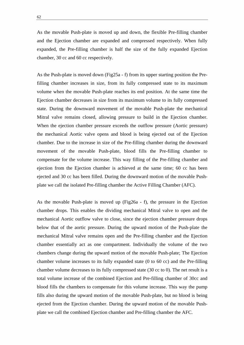
62
As the movable Push-plate is moved up and down, the flexible Pre-filling chamber
and the Ejection chamber are expanded and compressed respectively. When fully
expanded, the Pre-filling chamber is half the size of the fully expanded Ejection
chamber, 30 cc and 60 cc respectively.
As the Push-plate is moved down (Fig25a - f) from its upper starting position the Pre-
filling chamber increases in size, from its fully compressed state to its maximum
volume when the movable Push-plate reaches its end position. At the same time the
Ejection chamber decreases in size from its maximum volume to its fully compressed
state. During the downward movement of the movable Push-plate the mechanical
Mitral valve remains closed, allowing pressure to build in the Ejection chamber.
When the ejection chamber pressure exceeds the outflow pressure (Aortic pressure)
the mechanical Aortic valve opens and blood is being ejected out of the Ejection
chamber. Due to the increase in size of the Pre-filling chamber during the downward
movement of the movable Push-plate, blood fills the Pre-filling chamber to
compensate for the volume increase. This way filling of the Pre-filling chamber and
ejection from the Ejection chamber is achieved at the same time; 60 cc has been
ejected and 30 cc has been filled. During the downward motion of the movable Push-
plate we call the isolated Pre-filling chamber the Active Filling Chamber (AFC).
As the movable Push-plate is moved up (Fig26a - f), the pressure in the Ejection
chamber drops. This enables the dividing mechanical Mitral valve to open and the
mechanical Aortic outflow valve to close, since the ejection chamber pressure drops
below that of the aortic pressure. During the upward motion of the Push-plate the
mechanical Mitral valve remains open and the Pre-filling chamber and the Ejection
chamber essentially act as one compartment. Individually the volume of the two
chambers change during the upward motion of the movable Push-plate; The Ejection
chamber volume increases to its fully expanded state (0 to 60 cc) and the Pre-filling
chamber volume decreases to its fully compressed state (30 cc to 0). The net result is a
total volume increase of the combined Ejection and Pre-filling chamber of 30cc and
blood fills the chambers to compensate for this volume increase. This way the pump
fills also during the upward motion of the movable Push-plate, but no blood is being
ejected from the Ejection chamber. During the upward motion of the movable Push-
plate we call the combined Ejection chamber and Pre-filling chamber the AFC.

63
In summation, the Vivicor™ pump generates a pulsating outflow, but a continuos
inflow throughout the pumping cycle (filling both during pump systole and diastole).
If the volume ratio between the Pre-filling chamber and the Ejection chamber is 1:2 as
discussed above and the ejection time is held at 50% of the pumping cycle time, the
flow rate of the inflow will be held at a constant level. Changes in ejection time can
easily be compensated for by changing the intra-chamber volume ratio accordingly,
thereby achieving a constant flow rate of the inflow throughout the pumping cycle.

64
Figure 25 a – f: Downward motion of the movable Push-plate; a) Push-plate start position, a-c) closing
of mechanical Mitral valve, d-f) opening of mechanical Aortic valve, and f) Push-plate end position
(F Monfront).
a) b)
c) d)
e) f)
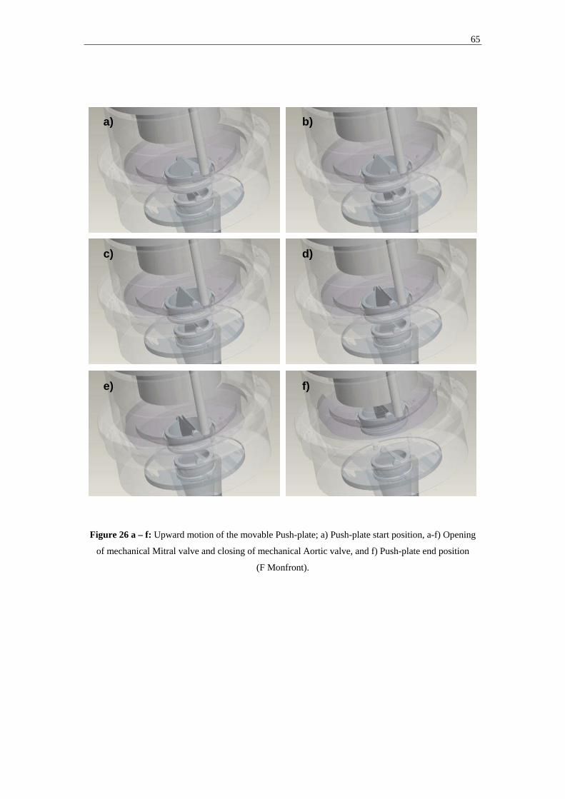
65
Figure 26 a – f: Upward motion of the movable Push-plate; a) Push-plate start position, a-f) Opening
of mechanical Mitral valve and closing of mechanical Aortic valve, and f) Push-plate end position
(F Monfront).
a) b)
c) d)
e) f)

66
5.1.2. Vivicor™ pump actuation and modes of operation
Downward movement of the Push-plate requires employment of an active force. This
can be achieved in multiple ways, including by use of electrical actuators,
electromagnetic actuation, and pneumatically powered push rod systems. All would
apply a force on the movable Push-plate, perpendicular to the upper surface of the
Push-plate.
Upward movement of the Push-plate can be achieved by employment of an active
force, pulling the Push-plate back to its upper starting position. This would allow the
pump to be operated in a “Fixed frequency – Active relocation” mode. Fixed
frequency will not allow responsiveness to changes in inflow pressure (Table3).
Upward movement of the Push-plate can also be achieved through passive relocation.
When the Push-plate has reached its end position some residual blood remains in the
ejection chamber after the mechanical Aortic valve has closed. The pressure of the
residual blood will be slightly lower than the aortic pressure, in a VAD application
typically in the range of 80 to 120 mmHg. The pressure on the upper surface of the
movable Push-plate will be lower than the pressure on the Ejection chamber side; The
larger part of the upper surface will be subject to the pressure inside the Pre-filling
chamber (<< 80 mmHg), and the peripheral parts of the upper surface will be subject
to atmospheric pressure. The net result is a pressure gradient acting on the movable
Push-plate, pulling it back up to its starting position. The strength of the force acting
on the movable Push-plate, and thereby also the time it takes for the Push-plate to
passively relocate back up to its starting position, is directly dependent upon the
pressure gradient acting upon it and the cross sectional area of the Push-plate,
determined by; FPush-plate = PPush-plate x APush-plate. As the mechanical Mitral valve opens
and the Push-plate starts its upward motion, the pressure in the Ejection chamber is
going to be the same as in the Pre-filling chamber. As a result there will be no
pressure gradient acting on the part of the Push-plate covered by the Pre-filling
chamber. However, there still exists a peripheral area on the upper surface of the
Push-plate, not covered by the Pre-filling chamber, upon which a pressure gradient
will act. This pressure gradient is determined by the difference in pressure in the
Ejection chamber, now equal to inflow pressure, and the atmospheric pressure. An

67
increased inflow pressure will increase the pressure gradient and thereby the strength
of the force acting upon the Push-plate, decreasing the time it will take for it to
relocate back up to its starting position. This will enable the pump to initiate its next
pumping cycle sooner, and as a result increase its output. This “Variable frequency”
or “full-to-empty” operation mode will allow the pump responsiveness to inflow
pressure, with a variable frequency / variable output as a result (Table3).
Finally, the Vivicor™ pump can also be operated in a “Fixed-frequency – Passive
relocation” mode in which the movable Push-plate is allowed to relocate passively,
but where the employment of an active force to move the Push-plate downward is
activated on a fixed frequency basis. This will allow the pump responsiveness to
inflow pressure, where an increase in inflow pressure will decrease Push-plate
relocation time. Based upon the level of inflow pressure, the Push-plate will relocate
upward as far as possible before the downward motion is initiated by activation of an
active force. This will result in a fixed frequency, but variable output mode of
operation (Table3).
Pump Operation Mode Pump
Rate
Output Push-plate relocation
Force
Ejection Force
Fixed-Frequency,
Active relocation
fixed fixed exerted externally exerted externally
Variable Frequency /
Full-to-empty
variable variable from internal pressure exerted externally
Fixed-Frequency,
Passive relocation
fixed variable from internal pressure exerted externally
Table 3: Vivicor™ possible modes of operation
5.2. Prototype System Component Design, Fabrication, and Actuation
5.2.1. Prototype System Architecture The design objectives going into the prototype design phase were to create a pump
system prototype that:

68
1. Enabled visualization of pump inflow and outflow
2. Enabled data acquisition of pump generated pressure and flow
3. Enabled cost effective fabrication (materials used and fabrication techniques)
4. Had a high degree of modularity for easy replacement of individual components
5. Could be actuated both by existing pneumatic VAD power units, and a PC
controlled linear stepper motor
As a result, a prototype VAD system architecture was designed that included a
prototype VAD with a separate actuator and control unit (Fig28).
Figure 27: System Architecture of the Vivicor™ prototype VAD system (M Stenberg)
The pump prototype was designed to be made out of Lexan® from GE Plastics
(Pittsfield, Ma), Aluminum, and T2 from Dow Corning (Midland, Michigan). Lexan®
and Aluminum were chosen for the low material cost, lightweight and for ease of
fabrication, as no stainless steel tools are needed for fabrication with these materials.
T2 was chosen for the flexible components (the Pre-filling chamber and the Push-
plate membrane) due to its mechanical properties of combining a high degree of
Pump external
ActuatorActuator
AirpistonAir
pistonSteppermotor
Steppermotor
DAQDAQ
PC control unitPC control unit
Pneumaticdrive and
control unit
Pneumaticdrive and
control unit
Push platePush plate Push platevalve
Push platevalve
EjectionchamberEjectionchamber
Pre-fillingchamber
Pre-fillingchamber
InletInlet
Outlet valveOutlet valve
OutletOutlet
Closed circuitClosed circuit
Pump Internal

69
flexibility and stretch (elongation: 250%), with a high threshold for tearing (tear
strength: 130-140 ppi). The pump was designed to be mounted on a Lexan® test rig
and connected to a pneumatic air piston, or linear motor, through two push rods
connecting with the pump internal moving components.
A rolling diaphragm air piston from Control Air (Amherst, NH) was used to allow for
connection to a Thoratec pneumatic power unit for actuation (TLC-II Drive).
As an alternative actuation mechanism, the Lexan® test rig was designed to facilitate
the mounting of a Series 57000 electric linear stepper motor from HSI (Waterbury,
CT) that could be controlled via a DAQ board and laptop PC.
Figure 28: AutoCad illustration of the Vivicor™ Prototype set-up, pneumatic actuation set-up,
excluding pneumatic power unit (M Stenberg)
5.2.2. Component Design and Fabrication
All design work was carried out in AutoCad to facilitate virtual assembly of
individual pump components and to allow for time efficient design changes. Please
refer to Appendix A for a detailed component assembly drawing and components
specifications.

70
Prototype fabrication involved machining of individual pump components in Lexan®
and Aluminum, as well as molding of the flexible Pre-filling chamber and the flexible
pump membrane, dividing the Pre-filling chamber from the Ejection chamber.
Fabrication of Lexan® and Aluminum components was carried out in the workshop
of the Mechanical and Aerospace Engineering Department of University of Florida.
The need to create and test multiple designs of the Pre-filling chamber and pump
membrane, meant creating a fabrication process that would allow for rapid and cost
effective molding. For the Pre-filling chamber a modified lost wax method was used.
The process involved four separate steps (Fig29):
1) Creating a solid mold core corresponding to the inner contour of the Pre-
filling chamber
- A computer model of the contour was created in AutoCad
- A real size core was printed using a ZPrinter 310 System 3D printer
(Burlington, Ma)
- The surface of the printed core was smoothened and varnished
2) Creating a negative mold of the inner contour of the Pre-filling chamber
- The printed core was submerged in T2
- The T2 was allowed to set before it was cut in half to allow for removal of the
printed core
3) Creating a wax mold core corresponding to the inner contour of the Pre-
filling chamber
- The negative T2 mold was closed and wax was pored into it at 175° F
- Once the wax had set, the mold was opened to release the wax core
4) Creating a T2 Pre-filling chamber
- The wax core was mounted axially and horizontally on a rotary motor
- T2 was applied to the spinning wax core using a syringe
- The T2 was distributed evenly on the spinning wax core to an approximate
thickness of 0,7 mm
- The T2 surface was allowed to set before the wax was melted from within the
T2 coating in an oven at 200° F.
- Any wax residue was cleaned from the T2 Pre-filling chamber

71
Figure 29: The lost wax molding process of the flexible Pre-filling chamber (M Stenberg)
The pump membrane was also molded using a custom made cavity mold with an
adjustable length membrane thickness spacer, also acting as a center guide (Fig30).
Figure 30: The cavity molding set-up of the pump membrane (M Stenberg)
1&2 3 3
4 4
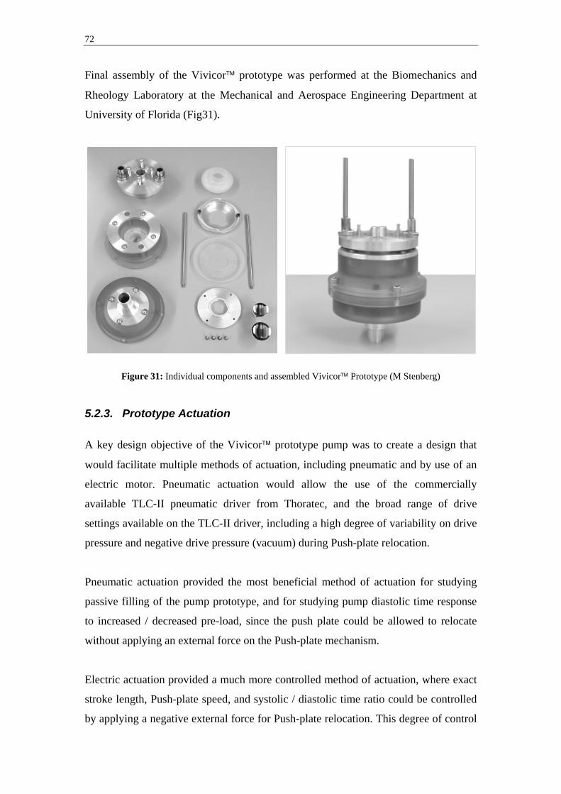
72
Final assembly of the Vivicor™ prototype was performed at the Biomechanics and
Rheology Laboratory at the Mechanical and Aerospace Engineering Department at
University of Florida (Fig31).
Figure 31: Individual components and assembled Vivicor™ Prototype (M Stenberg)
5.2.3. Prototype Actuation A key design objective of the Vivicor™ prototype pump was to create a design that
would facilitate multiple methods of actuation, including pneumatic and by use of an
electric motor. Pneumatic actuation would allow the use of the commercially
available TLC-II pneumatic driver from Thoratec, and the broad range of drive
settings available on the TLC-II driver, including a high degree of variability on drive
pressure and negative drive pressure (vacuum) during Push-plate relocation.
Pneumatic actuation provided the most beneficial method of actuation for studying
passive filling of the pump prototype, and for studying pump diastolic time response
to increased / decreased pre-load, since the push plate could be allowed to relocate
without applying an external force on the Push-plate mechanism.
Electric actuation provided a much more controlled method of actuation, where exact
stroke length, Push-plate speed, and systolic / diastolic time ratio could be controlled
by applying a negative external force for Push-plate relocation. This degree of control

73
guaranteed exact replication of each stroke and provided the most beneficial method
of actuation for monitoring pump prototype generated inflow and outflow pressure
and flow.
Figure 32: The Vivicor™ Prototype mounted in a Lexan® box and connected to a Control Air air
piston, and a HSI stepper motor respectively (M Stenberg)
5.2.4. Data Acquisition
An integrated data acquisition system was designed to allow the capture and logging
of multiple pressures, as well as pulsating flow. Two DP15 pressure transducers (with
an accuracy of +/- 0,25%) and a CD280 Multi-Channel Carrier Demodulator from
Validyne (Northridge, Ca) were used to detect pressure, and an FT10 Flow
Technology (Phoenix, Az) in-line turbine flow meter was used to detect real time
pulsating flow (with an accuracy of +/- 0,05%). For collection of signals from the
pressure and flow transducers a DAQPad-6015 DAQ board from National
Instruments (Austin, Tx) was used connected to a PC laptop. Signals from the DAQ
board were fed into custom made programs for data processing and logging, based on
the National Instruments LabView software platform.

74
The pressure LabView program (see Appendix B for code) received a voltage signal
(0-10V) linearly related to the measured pressure. The pressure LabView program
applied the relevant multiple to transform the raw voltage signal to pressure in mmHg.
The LabView program then wrote the pressure data along with time into an excel file
for further data modulation.
The flow LabView program (see Appendix B for code) received a square wave signal
(0-10V). The frequency of the square wave was linearly related to the measured flow.
The flow LabView program filtered any noise with amplitude lower then 1V and
detected the pulse length of each filtered square wave pulse. The frequency was
calculated and the relevant multiple applied to transform the raw signal to flow data in
liters / minute. The LabView program then wrote the raw voltage signal along with
flow and time data into an excel file for further data modulation.
For recording of mean flow a stand-alone transonic tubing flow sensor from
Transonic Systems (Ithaca, NY) was used. The transonic flow meter allowed for non-
invasive flow recording and displayed mean flow for manual documentation, with a
reading tolerance of +/- 10%, and a maximum zero offset of +/- 60 ml / min.

75
6. In Vitro Evaluation
Four separate In Vitro experiments were performed to evaluate the pumping function
of the Vivicor™ prototype. All experiments were performed with the compliance
chamber vented to atmospheric pressure.
6.1. Experiment 1 - Characterization of pump in/outlet pressure The objective of test set-up no1 was to characterize pump inlet and outlet pressure and
further document the pump internal mechanics of the Vivicor™ pumping mechanism.
The prototype pump was mounted in the Lexan® test rig and actuated with the air
chamber connected to a Thoratec pneumatic drive module at 60 BPM. The pump inlet
and outlet were connected to a cardiopulmonary bypass circuit with a closed reservoir.
The circuit was filled with saline. The height of the reservoir over the pump
inlet/outlet could be varied to simulate different levels of pre-load. The experiment
was run on three different levels of pre-load, 25, 60, and 95 cmH2O (equaling 18, 44,
and 70 mmHg). 25 cmH2O corresponds most closely to a clinical situation. The two
levels of increased pre-load were run to accentuate pump response.
Pressure transducers were connected to the inlet and outlet tubing approximately 20
cm from the inlet and outlet respectively, using pitot needles facing upstream to detect
total (static + dynamic) pressure. Pressure readings showed a clear and repeatable
pattern. On the outlet side the onset of the ejection phase (Push-plate downward
movement) can be clearly identified by the rapid increase in pressure (Fig33 - A).
Shortly after onset of outlet pressure drop a pressure spike, corresponding to a similar
pressure spike in the inlet pressure, can be detected (Fig33 - B). Outlet pressure then
settles at pre-load level, before cycle is repeated.
Inlet pressure increases slightly and stabilizes around pre-filling level during the
ejection phase, but spikes at the point where the push-plate reaches its end position
(Fig33 - C). Pressure remains constant on the higher level before a rapid pressure
reduction and thereafter stabilization around the zero pressure level.

76
Figure 33: Inlet and outlet pressure at 25 cmH2O (18 mmHg pre-load)
Prolonged constant inlet pressure at the point of Push-plate end position can be clearly
observed at the higher levels of pre-load; 60 and 95 cmH2O (Fig34).
Figure 34: Inlet pressure at 25, 60 and 95 cmH2O (18, 44 and 70 mmHg pre-load)
Inlet pressure
-50
0
50
100
150
200
0 0,2 0,4 0,6 0,8 1 1,2 1,4 1,6 1,8 2
Time (sec)
Pres
sure
(mm
Hg)
18 mmHg44 mmHg70 mmHg
In/Outlet Pressure at 18mmHg Pre-load
-50
0
50
100
150
200
0 0,5 1 1,5 2 2,5 3 3,5 4 4,5 5
Time (sec)
Pres
sure
(mm
Hg)
Inlet pressureOutlet pressure
B: Outlet pressure spike
C: Inlet pressure spike
A: Onset of ejection phase

77
6.2. Experiment 2 - Characterization of pre-load responsiveness
The objective of test set-up no2 was twofold; 1) verify that the Vivicor™ could fill
passively, with no active force needed to relocate Push-plate to its upper position, and
2) determine pump responsiveness to increased/decreased pre-load (mechanical self-
regulation of output).
The prototype pump was mounted in the Lexan® test rig and actuated with the air
chamber connected to a Thoratec pneumatic drive module at 60 BPM, using a drive
pressure of 220 mmHg. No vacuum was used to assist Push-plate relocation in order
to isolate relocation only from pump internal pressure. The pump inlet and outlet were
connected to the same cardiopulmonary bypass circuit with reservoir as in test set-up
no1. The circuit was filled with saline. The experiment was run on three different
levels of pre-load, 25, 60, and 95 cmH2O (equaling 18, 44, and 70 mmHg).
Pressure transducers were connected to the inlet and outlet tubing approximately 20
cm from the inlet and outlet respectively, using pitot needles facing upstream to detect
total (static + dynamic) pressure. Ejection time was detected from the pressure curves.
Push-plate relocation time was calculated by subtracting ejection time from total cycle
time (1 sec at 60 BPM). Relocation time decreases as pre-load is increased (Fig35).
Figure 35: Push-plate relocation time vs. pump pre-load
Push-plate relocation time vs Pre-load
0,63075
0,400250,3455
0
0,1
0,2
0,3
0,4
0,5
0,6
0,7
10 30 50 70
Pre-load (mmHg)
Tim
e (s
ec)

78
6.3. Experiment 3 - Characterization of mean output vs frequency
The objective of test set-up no3 was to determine the relationship between pump
mean output and frequency. This will provide a better understanding of the filling
restrictions of the Vivicor™ pump.
The same experimental set-up as in set-up no2 was used. The pump pneumatic driver
was run with a 220 mmHg drive pressure, and a –25 mmHg vacuum to ensure
complete relocation of the Push-plate. This was done to eliminate the risk of
experiencing reduced stroke volume due to incomplete relocation of the Push-plate.
Any reduced stroke volume would have to come from incomplete filling of the Pre-
filling chamber. The experiment was run at frequencies; 50, 60, 70, 80, and 90 BPM
at two different pre-load levels; 25, and 60 cmH2O (18 mmHg, and 44 mmHg).
Mean outflow was measured using a transonic flow meter that was clamped on the ½
inch outlet tubing of the cardiopulmonary bypass circuit. The result was plotted
against the theoretical maximum output of a displacement pump at each frequency
level, which can be calculated as “pump frequency” x “maximum stroke volume”. At
both pre-load levels the pump output slightly exceeds the theoretical maximum output
up to 65 BPM at which point pump output becomes lower then the theoretical
maximum. The 60 cmH2O (18 mmHg) pre-load level provides a slightly higher output
than the 25 cmH2O (18 mmHg) pre-load level at frequencies over 65 BPM (Fig36).
Figure 36: Mean outflow vs. pump frequency
Mean output vs frequency (tentative)
0
1
2
3
4
5
6
7
40 50 60 70 80 90 100
Frequency (BPM)
Out
put (
l/min
) Theoretical Output(l/min)
Real Output at 44mmHg
Real Output at 18mmHg
79
6.4. Experiment 4 - Characterization of pump in/outlet flow
The objective of test set-up no4 was to determine the nature and timing of inflow and
outflow, verifying the pulsating outflow similar to a pure displacement pump, and the
continuos (or double pulse) inflow unique to Dynamic Displacement based pump
designs.
The prototype pump was mounted in the Lexan® test rig and actuated with the
electric stepper motor to ensure active relocation of the Push-plate, a 50% ejection
phase with equal acceleration profiles for downward and upward movement of the
Push-plate, and finally limited stop time in the end positions. The motor was run at a
fixed frequency of 65 BPM.
Real time inlet and outlet flow was measured in two separate runs with the in-line
impeller flow meter mounted approximately 20 cm from the inlet and outlet of the
pump, respectively. The flow curves in l / min reveals pulsating outlet flow at 65
BPM (Fig37a), and “double pulsed” inlet flow at 130 BPM (Fig37b).
Figure 37a: Inlet real time flow in l / min
Inlet flow pattern
0
2
4
6
8
10
12
0 0,5 1 1,5 2
Time (sec)
Flow
rate
(l/m
in)
Inlet

80
Figure 37b: Inlet real time flow in l / min
Outlet flow pattern
0
2
4
6
8
10
12
0 0,5 1 1,5 2
Time (sec)
Flow
rate
(l/m
in)
Outlet
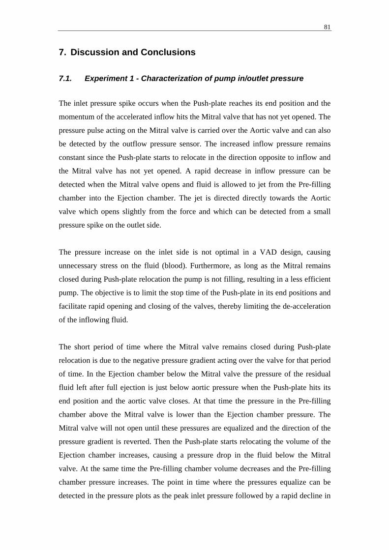
81
7. Discussion and Conclusions
7.1. Experiment 1 - Characterization of pump in/outlet pressure
The inlet pressure spike occurs when the Push-plate reaches its end position and the
momentum of the accelerated inflow hits the Mitral valve that has not yet opened. The
pressure pulse acting on the Mitral valve is carried over the Aortic valve and can also
be detected by the outflow pressure sensor. The increased inflow pressure remains
constant since the Push-plate starts to relocate in the direction opposite to inflow and
the Mitral valve has not yet opened. A rapid decrease in inflow pressure can be
detected when the Mitral valve opens and fluid is allowed to jet from the Pre-filling
chamber into the Ejection chamber. The jet is directed directly towards the Aortic
valve which opens slightly from the force and which can be detected from a small
pressure spike on the outlet side.
The pressure increase on the inlet side is not optimal in a VAD design, causing
unnecessary stress on the fluid (blood). Furthermore, as long as the Mitral remains
closed during Push-plate relocation the pump is not filling, resulting in a less efficient
pump. The objective is to limit the stop time of the Push-plate in its end positions and
facilitate rapid opening and closing of the valves, thereby limiting the de-acceleration
of the inflowing fluid.
The short period of time where the Mitral valve remains closed during Push-plate
relocation is due to the negative pressure gradient acting over the valve for that period
of time. In the Ejection chamber below the Mitral valve the pressure of the residual
fluid left after full ejection is just below aortic pressure when the Push-plate hits its
end position and the aortic valve closes. At that time the pressure in the Pre-filling
chamber above the Mitral valve is lower than the Ejection chamber pressure. The
Mitral valve will not open until these pressures are equalized and the direction of the
pressure gradient is reverted. Then the Push-plate starts relocating the volume of the
Ejection chamber increases, causing a pressure drop in the fluid below the Mitral
valve. At the same time the Pre-filling chamber volume decreases and the Pre-filling
chamber pressure increases. The point in time where the pressures equalize can be
detected in the pressure plots as the peak inlet pressure followed by a rapid decline in

82
pressure. This conclusion was verified by the prolonged Mitral valve closure time at
higher pre-loads, where a greater Ejection chamber volume increase was needed to
equalize the pressures, as visible in Fig34.
The unwanted Mitral closure time, and corresponding pressure increase, can be
minimized by limiting the residual volume left in the Ejection chamber after full
ejection.
Pressure data accuracy (sensor accuracy of +/- 0,25%) is well within acceptable levels
and the pressure and time data collected is a good representation of actual conditions.
7.2. Experiment 2 - Characterization of pre-load responsiveness
The Push-plate relocation time increased as the pump pre-load increased. Experiment
2 verified the ability of the Vivicor™ pump to passively relocate its Push-plate, and
thereby the mechanical self-regulating feature of the pump. This gives the Vivicor™
embodiment of a Dynamic Displacement Pump the same self-regulating capabilities
as pure Displacement Pumps. This allows the Vivicor™ pump to automatically vary
its output based on the level of pre-load. This requires only active displacement of the
Push-plate, no active relocation.
The actual relocation times of the current version of the Vivicor™ pump used in this
experimental set-up should not, however, be regarded as a benchmark for a clinical
version of the pump. Due to the rubber membrane in the air piston used to actuate the
Vivicor™ pump in this experiment, the air chamber is applying a force onto the Push-
plate in the downward direction when no pressure/vacuum is applied. Also, the weight
of the steel plunger of the air piston requires an extra force from the Push-plate in
order to relocate it to its upper position. Both of these forces reduce the positive
pressure gradient acting on the Push-plate, enabling relocation to its upper position.
However, neither of these forces are representative of a clinical version, in which for
instance an electromagnetic actuation system can be made to eliminate these forces,
allowing for a more rapid relocation of the Push-plate.

83
Pressure data accuracy (sensor accuracy of +/- 0,25%) is well within acceptable levels
and the pressure and time data collected is a good representation of actual conditions.
7.3. Experiment 3 - Characterization of mean output vs frequency
Experiment 3 revealed that pump output did not increase linearly with increased pump
frequency. The pump was more efficient than a displacement pump at frequencies up
to 65 BPM and less efficient than a displacement pump at frequencies over to 65
BPM.
As can be observed in the outlet pressure plots, Fig33, a small jet of fluid ejects
through the Mitral valve and on through the pump Aortic valve, at the time of Mitral
valve opening. This occurs during Push-plate relocation and produces an extra
contribution to pump output, which would not be seen in a regular displacement
pump. This generates a higher mean outflow that what would be observed in a
displacement pump, as evident by Fig36.
The vacuum applied to the air piston ensured that the gradual loss of pump efficiency,
evident by the non-linear mean output curve, did not stem from incomplete relocation
of the Push-plate and thereby non-utilization of the full stroke length. This implies
that the full stroke volume is not utilized during the pumping cycle.
During Push-plate relocation, pump filling comes from the Pre-filling and Ejection
chambers acting as one common chamber (the active filling chamber). The Pre-filling
chamber of actively compressed from 30 cc to 0 cc, while the Ejection chamber is
actively forced to increase from 0 cc to 30 cc, resulting in a 30 cc net volume increase.
During this phase full utilization of the maximum stroke volume is guarantied, since
external active forces force all volume changes.
However, during Push-plate down movement (the ejection phase) pump filling stems
only from the volume increase of the Pre-filling chamber not acting alone as the
active filling chamber. The Ejection chamber is isolated by a closed Mitral valve and
is currently ejecting fluid from the pump. The expansion of the Pre-filling chamber
from 0 cc to 30 cc is in part passive. The axial length increase of the flexible Pre-

84
filling chamber is a result from an actively forced downward movement of the Push-
plate, but the diameter increase of the Pre-filling chamber is a direct effect of the
internal pressure of the chamber alone, being the pressure of the inflowing fluid. No
external force helps expand the Pre-filling chamber from the outside. If the pressure
of the inflowing fluid (the pre-load) is low and/or if the vascular resistance in the inlet
is high the Pre-filling chamber will not fill completely resulting in a lower net output.
This is demonstrated by the fact that mean outflow in the experimental set-up was
higher at the higher pre-load level of 60 cmH2O (18 mmHg) than the lower level of 25
cmH2O (18 mmHg).
This feature is a double-edged sword. The present Vivicor™ pump version does not
actively aspirate fluid into the pump during the ejection phase, only during Push-plate
relocation. This results in a reduced output, but at the same time it provides an
important safety feature, since the pump will not be able to cause ventricular collapse
in an event where blood flow into the pump is restricted.
Based on more information of the future final employment of the Vivicor™ pump,
such as insertion sites, desired minimum output, and cannulae size which effects
inflow resistance, an assessment of the need for active aspiration of blood into the
pump can be made. In the event this is needed the volume outside the Pre-filling
chamber can be filled with a low-density gas that allows for expansion. Gas pressure
can be pre-set at a level lower than mean inflow pressure resulting in an active
external expansion of the Pre-filling chamber. Gas expansion would require more
energy than Push-plate displacement alone, but the expanded gas would act as an air
spring during Push-plate relocation eliminating the need for active relocation and thus
reduce energy consumption.
This would also enclose the pump completely, eliminating the need for a pump
external compliance chamber due to the 30 cc pump internal displacement during the
60 cc ejection phase. The Vivicor™ pump has already reduced the need for
displacement from 60 cc to 30 cc compared to a pure Displacement Pump.
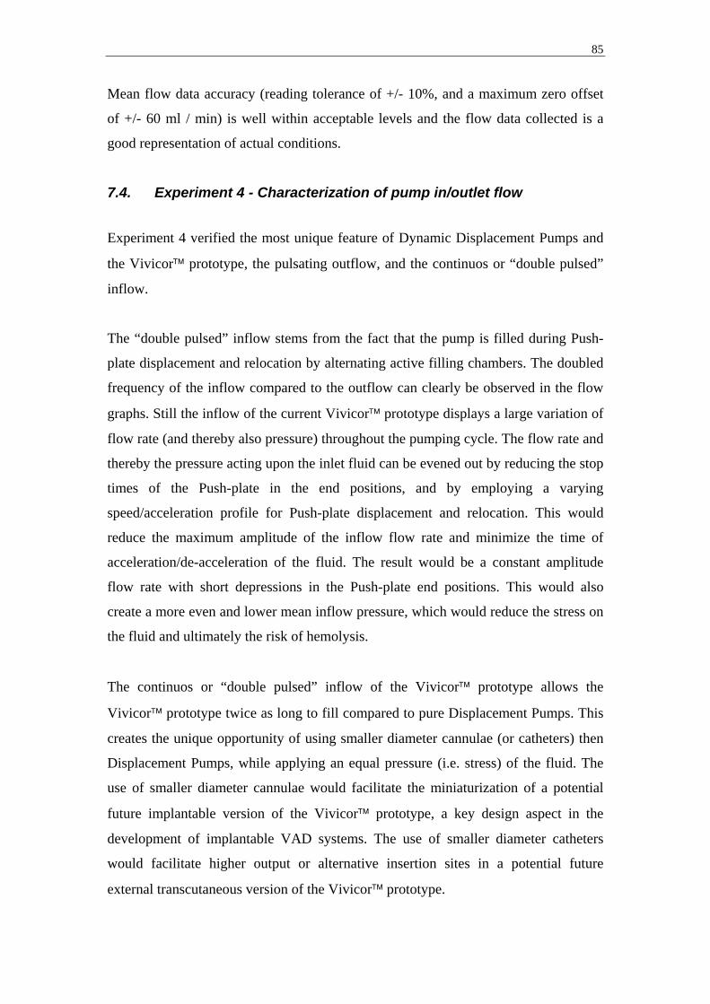
85
Mean flow data accuracy (reading tolerance of +/- 10%, and a maximum zero offset
of +/- 60 ml / min) is well within acceptable levels and the flow data collected is a
good representation of actual conditions.
7.4. Experiment 4 - Characterization of pump in/outlet flow
Experiment 4 verified the most unique feature of Dynamic Displacement Pumps and
the Vivicor™ prototype, the pulsating outflow, and the continuos or “double pulsed”
inflow.
The “double pulsed” inflow stems from the fact that the pump is filled during Push-
plate displacement and relocation by alternating active filling chambers. The doubled
frequency of the inflow compared to the outflow can clearly be observed in the flow
graphs. Still the inflow of the current Vivicor™ prototype displays a large variation of
flow rate (and thereby also pressure) throughout the pumping cycle. The flow rate and
thereby the pressure acting upon the inlet fluid can be evened out by reducing the stop
times of the Push-plate in the end positions, and by employing a varying
speed/acceleration profile for Push-plate displacement and relocation. This would
reduce the maximum amplitude of the inflow flow rate and minimize the time of
acceleration/de-acceleration of the fluid. The result would be a constant amplitude
flow rate with short depressions in the Push-plate end positions. This would also
create a more even and lower mean inflow pressure, which would reduce the stress on
the fluid and ultimately the risk of hemolysis.
The continuos or “double pulsed” inflow of the Vivicor™ prototype allows the
Vivicor™ prototype twice as long to fill compared to pure Displacement Pumps. This
creates the unique opportunity of using smaller diameter cannulae (or catheters) then
Displacement Pumps, while applying an equal pressure (i.e. stress) of the fluid. The
use of smaller diameter cannulae would facilitate the miniaturization of a potential
future implantable version of the Vivicor™ prototype, a key design aspect in the
development of implantable VAD systems. The use of smaller diameter catheters
would facilitate higher output or alternative insertion sites in a potential future
external transcutaneous version of the Vivicor™ prototype.
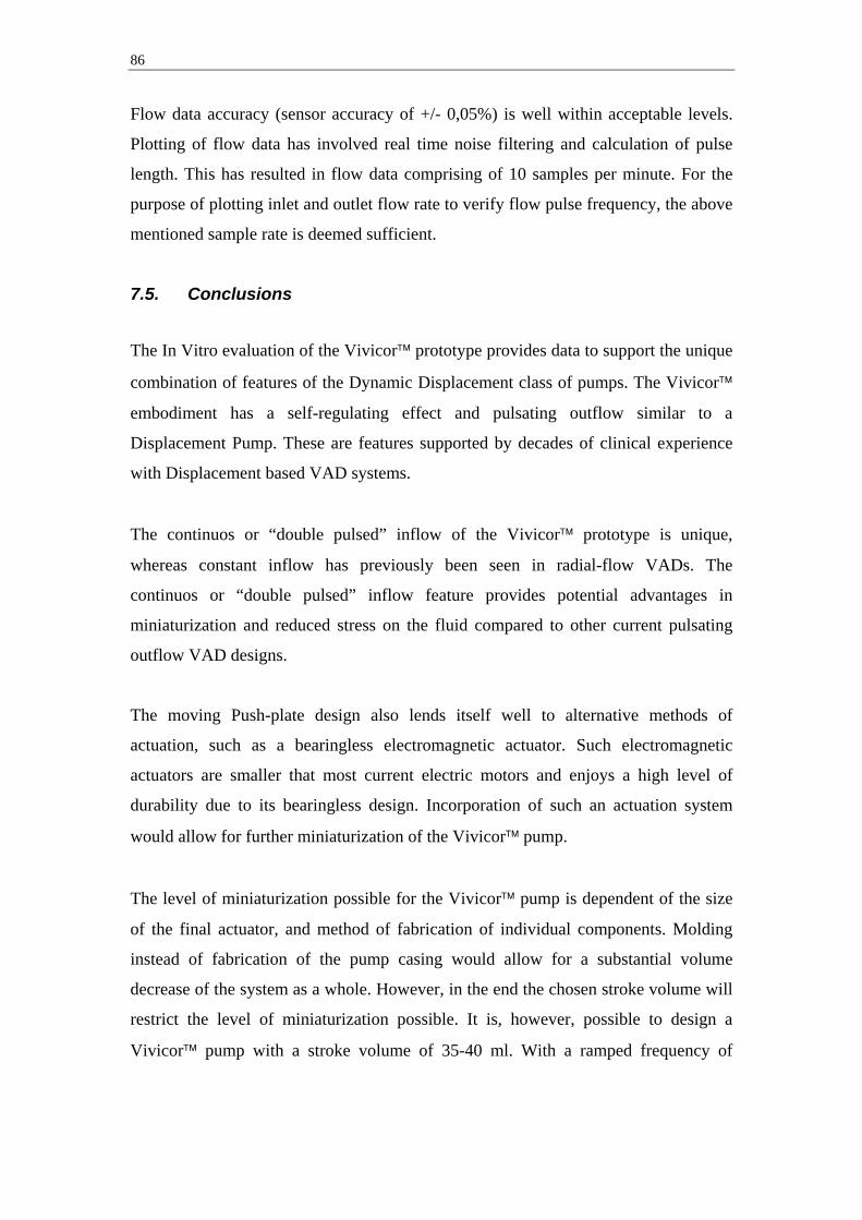
86
Flow data accuracy (sensor accuracy of +/- 0,05%) is well within acceptable levels.
Plotting of flow data has involved real time noise filtering and calculation of pulse
length. This has resulted in flow data comprising of 10 samples per minute. For the
purpose of plotting inlet and outlet flow rate to verify flow pulse frequency, the above
mentioned sample rate is deemed sufficient.
7.5. Conclusions
The In Vitro evaluation of the Vivicor™ prototype provides data to support the unique
combination of features of the Dynamic Displacement class of pumps. The Vivicor™
embodiment has a self-regulating effect and pulsating outflow similar to a
Displacement Pump. These are features supported by decades of clinical experience
with Displacement based VAD systems.
The continuos or “double pulsed” inflow of the Vivicor™ prototype is unique,
whereas constant inflow has previously been seen in radial-flow VADs. The
continuos or “double pulsed” inflow feature provides potential advantages in
miniaturization and reduced stress on the fluid compared to other current pulsating
outflow VAD designs.
The moving Push-plate design also lends itself well to alternative methods of
actuation, such as a bearingless electromagnetic actuator. Such electromagnetic
actuators are smaller that most current electric motors and enjoys a high level of
durability due to its bearingless design. Incorporation of such an actuation system
would allow for further miniaturization of the Vivicor™ pump.
The level of miniaturization possible for the Vivicor™ pump is dependent of the size
of the final actuator, and method of fabrication of individual components. Molding
instead of fabrication of the pump casing would allow for a substantial volume
decrease of the system as a whole. However, in the end the chosen stroke volume will
restrict the level of miniaturization possible. It is, however, possible to design a
Vivicor™ pump with a stroke volume of 35-40 ml. With a ramped frequency of

87
operation such a system could provide an output of up to 5 l / min at a total size
equivalent to most current radial-flow VAD systems.
This unique combination of pump features makes the Vivicor™ pumping technology
highly interesting for further development and evaluation for use in ventricular assist
applications.

88
8. Future Work and Development 8.1. Short term objectives In Vitro evaluation of the first-generation prototype of the Vivicor™ pump has
provided data to support technical proof-of-concept for dynamic displacement based
pumps. The in and outflow characteristics have been mapped, providing a better
understanding of the Vivicor™ pumping mechanism. However, the first-generation
prototype was deliberately oversized for visualization purposes, and it was designed
to pump saline/water, with a viscosity much lower than blood.
Further In Vitro evaluation of the Vivicor™ pumping concept is needed. The next step
in development is to design and fabricate a second-generation prototype that will
allow for extended In Vitro evaluation by pumping of blood and fluids with a
viscosity equivalent to blood, such as a 40/60 Glycerol/water mix.
The second-generation prototype should incorporate an Ejection chamber that allows
for only minimal residual volume at full Push-plate displacement to further evaluate
the effect of Ejection chamber residual volume on Mitral valve opening time. The
second-generation prototype should also allow for the application of variable pressure
in the volume outside the Pre-filling chamber (the Compliance chamber) to further
evaluate the effect of Pre-filling chamber external pressure on pump filling time and
output at higher frequencies.
Furthermore, a second-generation prototype will need to be miniaturized and actuated
with an electronic motor to allow for increased control of Push-plate movement in
both directions.
Short term the primary evaluation areas of interest are:
- Evaluate pump performance and in/outflow characteristics while pumping fluids
with higher viscosity equivalent to blood (40/60 Glycerol/water mix). This will
provide more adequate data on in/outlet pressure and flow compared to
saline/water.

89
- Evaluate level of inlet suction throughout pumping cycle and its relation to
pressure settings in the volume outside of the Pre-filling chamber. This will
provide a better understanding of the level of suction the pump can produce and
the geometric restrictions on inflow cannulaes/catheters.
- Evaluate current level of hemolysis. This will provide a first level of reference for
the upcoming flow simulation/optimization phase.
- Evaluate pump performance under probable clinical conditions by simulating
normal clinical scenarios and abnormal scenarios known to occur in clinical VAD
use (occluded in/outlets, etc). This will provide valuable information of pump
performance and the need for further control and alarm systems.
8.2. Long term objectives
The purpose of the first-generation prototype and the second-generation prototype
proposed above has been In Vitro evaluation and pump characterization. The
objective has been to verify the validity of dynamic displacement based pumping
technologies for use in VAD systems, to show technical proof-of-concept.
The next step in the long-term development of the Vivicor™ VAD system is the
development of a third-generation prototype for In Vivo evaluation in an animal
model such as pig. The third-generation prototype will be a full system prototype,
including a clinically suited actuation mechanism and control system. This will
involve addressing issues that had been outside the scope the current licentiate project,
such as an electromagnetic actuation system, energy transfer, and pump internal fluid
simulation.
Four separate tasks are crucial in the development of a third-generation In Vivo
prototype:
- Incorporation of an electromagnetic actuation system to facilitate the magnetic
levitation of the Push-plate and the elimination of pump internal bearings. Apart
from providing a much increased level of durability and mechanical reliability

90
compared to currently electrically powered pulsating VADs, such a system will
provide unparalleled control of Push-plate movement. A concept of an
electromagnetic actuation system for the Vivicor™ pump involving an
electromagnetic field generated by coils mounted outside the pump casing, and
permanent magnets mounded on the Push-plate (as previously discussed by
Stenberg [2]) has been designed by Dr Khai Ngo at the Department of Electrical
Engineering, University of Florida.
- Further miniaturization of the pump by optimization of mechanical design and the
use of alternative fabrication methods such as molding of pump casings.
- Incorporation of a modular mechanical design, that will allow the pump to be
assembled by replaceable modular components, such as inlet, outlet, pump
housing, wires, etc. This will enable fast and easy replacement of individual
components by the operator in the event of malfunction. A modular design will
also allow for faster and cheaper upgrading of individual components.
- Comprehensive computer based fluid analysis/optimization of pump internal flow
characteristics (loads and shear stress), taking into account the moving boundaries
of the pump. This will provide necessary information of the level of load/stress
and location of wakes, areas of turbulence, etc, to be used in the final design of
pump internal contours.

91
9. Acknowledgements My supervisor Dr Håkan Elmqvist is a brave man, letting me carry out this project in
sunny Florida with plenty of fun filled distractions. However, your venture did pay
off. Thank you for your continued guidance, support and belief in me and the
Vivicor™ project.
Also, thank you Dr Roger Tran-Son-Tay and Dr Charles Klodell for your close
collaboration and guidance throughout my stay at the University of Florida. Your
support both professionally and personally has been very important to me. I greatly
value your friendship.
A large group of individuals have shown a great deal of passion and interest in the
Vivicor™ project throughout my stay at University of Florida. I would like to thank
the following individuals for their support in the design, prototyping, fabrication and
initial In Vitro testing of the Vivicor™ pump; Darren Thomas, Ethan Sherman,
Barbara Garita, Frank Bova, Khai Ngo, Chris Batich, Fabien Monfront, and the hard
working student team from the Integrated Product and Process Development (IPPD)
program; Ella Kinberg, Ariane Aniban, Jacob Cazares, Dena Mohnani, Mike Sim and
Brian Stankiewicz.
Thank you also, Karl Zawoy and the Office and Technology Licensing (OTL) team
for remaining the biggest Vivicor™ supporters, and always supporting the project
from a business development perspective.
Finally, and most importantly, Anna and my friends and family in Sweden, whose
support is the very reason why I have been able to carry out this project.
This work has been made possible in part by funding from the Swedish Heart and
Lung Association. I also wish to acknowledge Carbomedics Corp (Austin, Tx) for
their generous donation of mechanical heart valves for the Vivicor™ In Vitro
prototype.
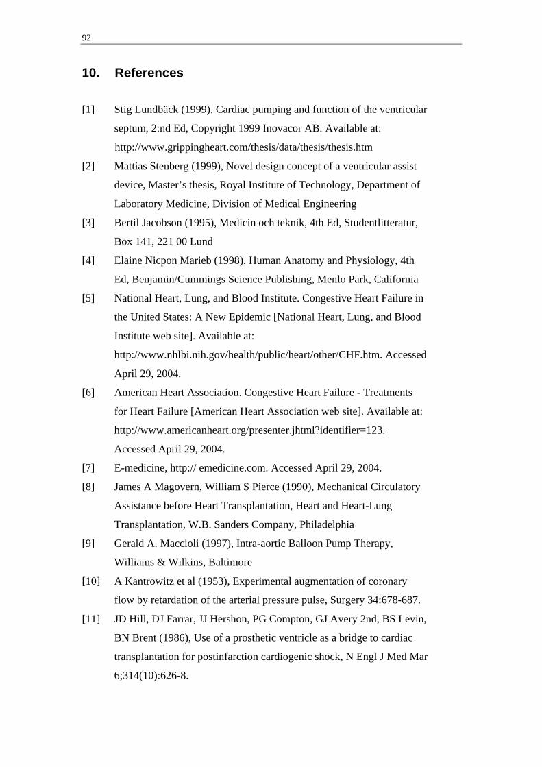
92
10. References
[1] Stig Lundbäck (1999), Cardiac pumping and function of the ventricular
septum, 2:nd Ed, Copyright 1999 Inovacor AB. Available at:
http://www.grippingheart.com/thesis/data/thesis/thesis.htm
[2] Mattias Stenberg (1999), Novel design concept of a ventricular assist
device, Master’s thesis, Royal Institute of Technology, Department of
Laboratory Medicine, Division of Medical Engineering
[3] Bertil Jacobson (1995), Medicin och teknik, 4th Ed, Studentlitteratur,
Box 141, 221 00 Lund
[4] Elaine Nicpon Marieb (1998), Human Anatomy and Physiology, 4th
Ed, Benjamin/Cummings Science Publishing, Menlo Park, California
[5] National Heart, Lung, and Blood Institute. Congestive Heart Failure in
the United States: A New Epidemic [National Heart, Lung, and Blood
Institute web site]. Available at:
http://www.nhlbi.nih.gov/health/public/heart/other/CHF.htm. Accessed
April 29, 2004.
[6] American Heart Association. Congestive Heart Failure - Treatments
for Heart Failure [American Heart Association web site]. Available at:
http://www.americanheart.org/presenter.jhtml?identifier=123.
Accessed April 29, 2004.
[7] E-medicine, http:// emedicine.com. Accessed April 29, 2004.
[8] James A Magovern, William S Pierce (1990), Mechanical Circulatory
Assistance before Heart Transplantation, Heart and Heart-Lung
Transplantation, W.B. Sanders Company, Philadelphia
[9] Gerald A. Maccioli (1997), Intra-aortic Balloon Pump Therapy,
Williams & Wilkins, Baltimore
[10] A Kantrowitz et al (1953), Experimental augmentation of coronary
flow by retardation of the arterial pressure pulse, Surgery 34:678-687.
[11] JD Hill, DJ Farrar, JJ Hershon, PG Compton, GJ Avery 2nd, BS Levin,
BN Brent (1986), Use of a prosthetic ventricle as a bridge to cardiac
transplantation for postinfarction cardiogenic shock, N Engl J Med Mar
6;314(10):626-8.

93
[12] Rose E et al (2001), Long term use of a left ventricular assist device for
end-stage heart failure, N Engl J Med, 345(20), 1435-1443
[13] Datamonitor (2002), Treatment Algorithms 2002: Heart Failure,
Publication no: DMHC1758, Datamonitor USA, New York, New York
[14] Curtis J, Wagner-Mann C, Extracorporeal Support: Centrifugal
Pumps. In Goldstein D, Oz M, eds. Cardiac Assist Devices. New York:
Futura Publishing Company, Inc, 2000:215-33
[15] Dasse KA, Chipman SD, Sherman CN, et al, Clinical experience with
textured blood-contacting surfaces in ventricular assist devices, ASAIO
Trans 1987;10:418-425
[16] Slater JP, Rose EA, Levin HR, et al, Low thromboembolic risk without
anticoagulation using advanced-design left ventricular assist devices,
Ann Thorac Surg 1996;62:1321-1327
[17] T Akutsu (1983), Mechanics, Control, Performance and Clinical
Applications of Left Ventricular Assist Devices, Advanced
cardiovascular Phys vol 5 (Part IV), pp 161-183, Karger & Basel
[18] Michael Broome’ et al (1999), Introduktion till Thoraxanestesi,
Thoraxkirurgi, Thoraxintensivvård enligt Umeåmodellen, Verson 99-
04-25, Hjärtcentrum, Umeå
[19] JL Dubois-Rande,E Teiger, J Garot, E Aptecar, JM Pernes, D Tixier, P
Gueret, D Loisance, P Dupouy (1998), Effects of the 14F hemopump
on coronary hemodynamics in patients undergoing high-risk coronary
angioplasty, Am Heart J May 135(5 Pt 1):844-9
[20] David J Farrar, Peter G Compton, John H Lawson, James J Hershon, J
Donald Hill (1986), Control Modes of a Clinical Ventricular Assist
Device, IEEE Engineering in medicine and biology magazine Mar
0739-5175/86/0300-0019$01.00
[21] KL Platt, TW Moore, O Barnea, SE Dubin, D Jaron (1993),
Performance optimization of left ventricular assistance. A computer
model study, ASAIO J Jan-Mar 39(1):29-38
[22] E Tayama, T Nakazawa, Y Takami, K makinouchi, S Ohtsubo, Y
Ohashi, AJ Andrade, J Glueck, J Mueller, Y nose (1997), The
hemolysis test of the Gyro C1E3 pump in pulsatile mode, Artif Organs
Jul 21(7):675-9

94
[23] B Krafte-Jacobs (1998), Effect of non-pulsatile renal blood flow on
plasma erythropoietin, Am J Hematol Feb 57(2):144-7
[24] H Konishi , Y Sohara, S Endo, Y Misawa, K Fuse (1997), Pulmonary
microcirculation during pulsatile and non pulsatile perfusion, ASAIO J
Sep-Oct 43(5):M657-9
[25] T Nishimura, E Tatsumi, S Takaichi, Y Taenaka, Y Wakisaka, T
Nakatani, T Masuzawa, Y Takewa, M Nakamura, S Endo, YS Sohn, H
Takano (1997), Morphologic changes of the aortic wall due to
reduced systemic pulse pressure in prolonged non pulsatile left heart
bypass, ASAIO J Sep-Oct 43(5):M691-5
[26] D Glenn Pennington, LR McBride, LW Miller, MT Swartz (1994),
Eleven years’ experience with the Pierse-Donachy ventricular assist
device, J Heart Lung Transplant Sep-Oct 13(5):803-10
[27] T Murakami, K Kino, H Irie, S Indo, S Kawakami, M Yamada, N
Shimizu (1994), Results of circulatory support for postoperative
cardiogenic shock, Artif organs Sep 18(9):691-7
[28] David J Farrar, Philip Litwak, John H Lawson, Robert S Ward,
Kathleen A White, A J Robinson, Robert Rodvien, J Donald Hill
(1988), In vivo evaluations of a new thromboresistant polyurethane for
artificial heart blood pumps, J Thorac Cardiovasc Surg 95:191-200
[29] Thoratec Ventricular Assist Device, Directions for use, 14751
(Rev.A), Thoratec Laboratories Corporation, 2023 8:th St, Berkeley,
California 94710 USA
[30] Stevenson, Kormos, et al, Mechanical cardiac support 2000 JACC Vol. 37,
No. 1, January 2001:340-70

95
11. VAD Company Web Links
Web address Company Product
BVS 5000
AB 5000
http://www.abiomed.com AbioMed
AbioCore
Intra-Aortic Balloon Pump
CorAide
http://www.arrowintl.com
Arrow International
LionHeart (discontinued)
Excor (several sizes) http://www.berlinheart.com Berlin Heart
Incor
http://www.datascope.com DataScope CS100 / System 98XT
Impella Recover LP 2,5 &
LP 5,0
http://www.impella.com
Impella CardioSystems
Impella Recover
Biventricular system (LD
2,5 + RD 5,0)
http://www.jarvikheart.com Jarvik Heart Jarvik 2000 FlowMaker
http://www.medtronic.com Medtronic BioPump
(Two sizes)
http://www.micromedtech.com MicroMed DeBakey VAD
http://www.terumo-cvs.com Terumo DuraHeart
Thoratec VAD
Thoratec IVAD
HeartMate IP LVAS
HeartMate XVE LVAS
HeartMate II
http://www.thoratec.com Thoratec
HeartMate III
http://www.ventracor.com Ventracor VentrAssist
Novacor
Next Generation LVAS
http://www.worldheart.com WorldHeart
HeartQuest VAD

96
Appendix A - AutoCad Assembly Drawing and Component List
First-generation Vivicor™ Prototype
1
2
3
11
4
7
6
8
5
10
9
12
13
14
14
15
16
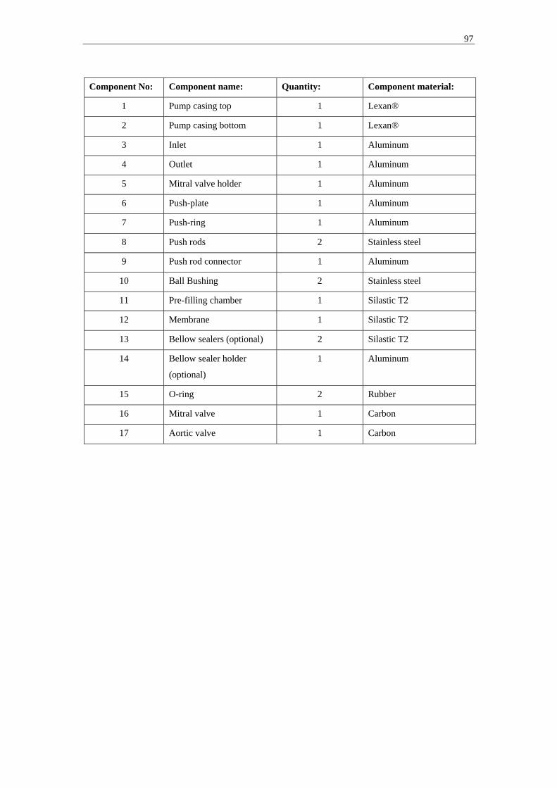
97
Component No: Component name: Quantity: Component material:
1 Pump casing top 1 Lexan®
2 Pump casing bottom 1 Lexan®
3 Inlet 1 Aluminum
4 Outlet 1 Aluminum
5 Mitral valve holder 1 Aluminum
6 Push-plate 1 Aluminum
7 Push-ring 1 Aluminum
8 Push rods 2 Stainless steel
9 Push rod connector 1 Aluminum
10 Ball Bushing 2 Stainless steel
11 Pre-filling chamber 1 Silastic T2
12 Membrane 1 Silastic T2
13 Bellow sealers (optional) 2 Silastic T2
14 Bellow sealer holder
(optional)
1 Aluminum
15 O-ring 2 Rubber
16 Mitral valve 1 Carbon
17 Aortic valve 1 Carbon
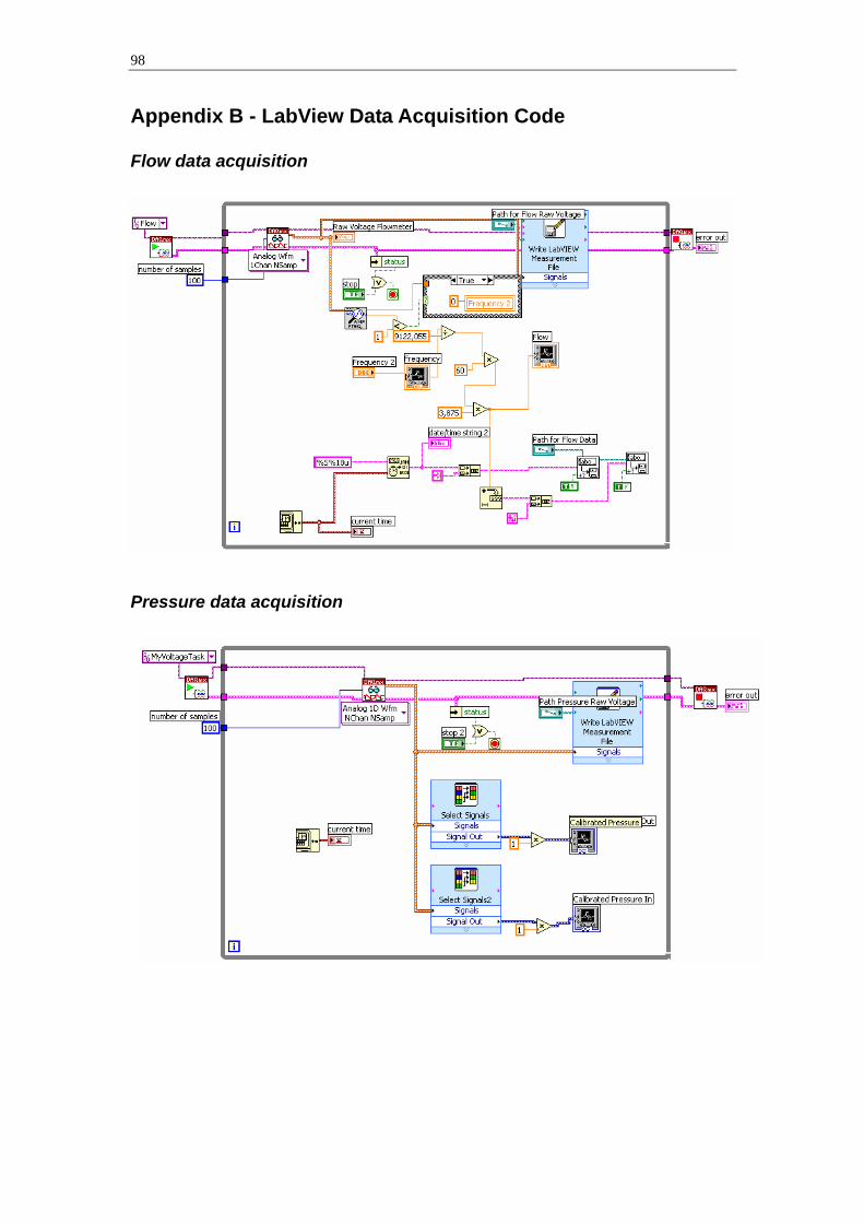
98
Appendix B - LabView Data Acquisition Code Flow data acquisition
Pressure data acquisition

99
Appendix C - LabView Motor Controller Code