computer zs1 1 − d/ze 2 graphics - university of...
TRANSCRIPT

cpsc/enel P 1
by
Brian Wyvill
University of Calgary
by
Brian Wyvill
University of Calgary
ComputerGraphicsComputerGraphics
3D transformationsand Viewing 3D Scenes
Zs=1
Zs=0
∆Zs1
∆Zs2
Zs= 1 − D/Ze
1 − D/F
Ze=FZe=D ∆Ze ∆Ze
xeye
ze
yw
zw
eye (Vfrom)Centre of Projection
xw
View to point
What we see
roll angle
Viewing or Near Plane
CCCCCCCCCCCCCCCCCCCCCCCCCCCCCCCCCCCCCCCCCCCCCCCCC
Viewing Frustrum
Yon or far Plane
Sy
d
f
(y, z)

cpsc/enel P 2
3D Coordinate Systems
x
y
zx
y
z
Right Handed System
Left Handed System
Right Handed System,
Axis (+)ve rotationx y to zy z to xz x to y
As if looking down the axisof rotation towards the origin, anti−clockwise is positive.
F&VD.1 p217F&VD.2 p180

cpsc/enel P 3
3D Transformations
Represented by 4x4 matrices. A point (x,y,z) is represented in homogeneous coordinates as (x,y,z,W) where W != 0
1 0 0 0
0 cosθ −sinθ 0
0 sinθ cosθ 0
0 0 0 1
Translation Using Column Vectors Scaling
Rotation About x−axis Rotation about y−axis Rotation about z−axis
cosθ −sinθ 0 0
sinθ cosθ 0 0
0 0 1 0
0 0 0 1
cosθ 0 sinθ 0
0 1 0 0
−sinθ 0 cosθ 0
0 0 0 1
1 0 0 Tx
0 1 0 Ty
0 0 1 Tz
0 0 0 1
Sx 0 0 0
0 Sy 0 0
0 0 Sz 0
0 0 0 1

cpsc/enel P 4
3D TransformationsContinued
For example a point 1 unit along the z−axis rotated 90o about y:
A point 1 unit along the x−axisz rotates positively to x about y * =
0 0 1 0
0 1 0 0
−1 0 0 0
0 0 0 1
0
0
1
1
1
0
0
1
x
z
y

cpsc/enel P 5
Special Orthogonal Matrices1. For the upper 2x2 matrix, the row vectors are unit
2. (cosθ −sinθ) and (sinθ cosθ) are perpendicular to eachother: (cosθ −sinθ).(sinθ cosθ) = cosθsinθ−sinθcosθ=0
3. take the determinant: cosθcosθ+sinθsinθ=1
Properties 1 and 2 are also true of the vectors formed by the columns: (cosθ sinθ) and (−sinθ cosθ) This defines a special orthogonal matrix
A transformation matrix which has such an upper 2x2 iscalled orthogonal i.e. transformations preserve angles andlengths. Matrices comprised of rotation and translationare orthogonal e.g. square when rotated stays a square
Similarly in 3D the upper left 3x3 matrix comprise mutuallyperpendicular unit vectors and the submatrix has adeterminant of unity.
cosθ −sinθ 0
sinθ cosθ 0
0 0 1
1 0 0
0 cosθ −sinθ
0 sinθ cosθ
cosθ 0 sinθ
0 1 0
−sinθ 0 cosθ
cosθ −sinθ 0
sinθ cosθ 0
0 0 1
cosθ −sinθ tx
sinθ cosθ ty
0 0 1

cpsc/enel P 6
Affine TransformationsA transformation matrix composed of scale, rotate and translate is affine, parallel lines are preserved but not lengths and angles.
square rotated and then scaled by 2 1. Lengths and angles of the square are not preserved but the sides remain parallel.
Shear transforms are also affine:
Shear in x: Shear in y:1 shx 0
0 1 0
0 0 1
1 0 0
shy 1 0
0 0 1

cpsc/enel P 7
The inverse of these transformations is:
Translation use −Tx −Ty −TzScaling use 1/Sx 1/Sy 1/SzRotation negate the angle of rotation
For an orthogonal matrix (rotation, translation) the transpose is the inverse.
To compute this simply exchange row and column indices.
Inverse of Transformations
Inverse
exchange
row and columns
for orthogonal matrix
1 0 0 0
0 cosθ −sinθ 0
0 sinθ cosθ 0
0 0 0 1
1 0 0 0
0 cosθ sinθ 0
0 −sinθ cosθ 0
0 0 0 1

cpsc/enel P 8
Composing 3D Transformations
Start position End position Translate to the origin
Rotate around y−axis Rotate around x−axis Rotate around z−axis
Rz.Rx.Ry.T

cpsc/enel P 9
Rotation About Arbitrary Axis
Start position
T to origin R y−axis R x−axis Rotate around z−axisby desired amount
Transform to z−axis Transform back to end position
TT.RTy.RT
x.Rz.Rx.Ry.T

cpsc/enel P 1 0
More Orthogonal Matrix PropertiesMultiply one of the row vectors (transposed) of the upper left 3x3 rotation matrixby the rotation matrix rotates the vector onto one of the principal axes.
Also: the middle row rotates into the y axisand the bottom row rotates into the z axis
−sinθ
0
cosθ
cosθ 0 sinθ
0 1 0−sinθ 0 cosθ
=
−sinθcosθ+cosθsinθ
0
cosθcosθ+sinθsinθ
= 0
0
1
Y rotation
0
cosθ
−sinθ
1 0 0
0 cosθ −sinθ
0 sinθ cosθ=
0
cosθcosθ+sinθsinθ
sinθcosθ−cosθsinθ
= 0
1
0
X rotation
cosθ
−sinθ
0
cosθ −sinθ 0
sinθ cosθ 0
0 0 1
=
cosθcosθ+sinθsinθ
sinθcosθ−cosθsinθ
0
= 1
0
0
Z rotation
similarly

cpsc/enel P 1 1
Using Orthogonal Matrix Properties
The example required Rz.Rx.Ry.T let R =r1x r2x r3x 0
r1y r2y r3y 0
r1z r2z r3z 00 0 0 1
The upper left 3x3 matrix handles the rotationthe bottom row rotates a vector into the z−axis.Consider the magenta vector in the example,call it V
The matrix will rotate (r1z r2z r3z)T into the z−axis but it also rotated V into the z−axis so
V is also (r1z r2z r3z)T ||V||
Similarly (r1x r2x r3x)T will be rotated into the x−axis. Given
a vector Q in the plane of the dinosaur that is also rotated into the zy plane with V then
(r1x r2x r3x)T = VxQ finally (r1y r2y r3y)T=VxVxQ
||VxQ|| ||VxVxQ||
V
Q

cpsc/enel P 1 2
Change of Coordinate System
0
1
2
3
45
6
A point system j can be transformed to system i by applying a matrix Mi j
Pi = Mi j * Pj
E.g. the point at (2,4)j is also at (3,5)i
For (2,4)j Scale by 0.5,0.5 = 1,2Translate by 2,3 = (3,5)i
For (3,5)i Translate by −2,−3 (1,2) Scale by (2,2) = (2,4)j
Similarly to transform from k to j with Mj k
Pi = Mi j * Mj k * Pk
Also Mj i = Mi j−1
System i
System j

cpsc/enel P 1 3
The Eye System
xeye
ze
yw
zw
eye (Vfrom)Centre of Projection
xw
View to point
What we see
roll angle
Viewing or Near Plane
!!!!!!!!!!!!!!!!!!!!!!!!!!!!!!!!!!!!!!!!!!!!!!!!!!!!!!!!!!!!!!!!!!!!!!!!!!!!!!!!!!!!!!!!!!!!!!!!!!!!!!!!!!!!!!!!!!!!!!!!!!!!!!!!!!!!!!!!!!!!!!!!!!!!!!!!!!!!!!!!!!!!!!!!!!!!!!!!!!!!!!!!!!!!!!!!!!!!!!!!!!!!!!!!!!!!!!!!!!!!!!!!!!!!!!!!!!!!!!!!!!!!!!!!!!!!!!!!!!!!!!!!!!!!!!!!!!!!!!!!!!!!!!!!!!!!!!!!!!!!!!!!!!!!!!!!!!!!!!!!!!!!!!!!!!!!!!!!!!!!!!!!!!!!!!!!!!!!!!!!!!!!!!!!!!!!!!!!!!!!!!!!!!!!!!!!!!!!!!!
Viewing Frustrum
Yon or far Plane
F&VD.1 p229F&VD.2 p193

cpsc/enel P 1 4
Transformations Into the Eye SystemIn this example the Vfrom is 5,6,4 The Vto is 2,1,0 the un−normalisedview vector is Vfrom−Vto = 3,5,4 the roll angle is 200
Rotate around the y Rotate around the x Translate to Vfrom
Eye system alignedwith world
Make left handedscale (1 1 −1)
Rotate aroundthe z (roll)

cpsc/enel P 1 5
Sy
Sx
Zeye
Yeye
Xeye
The Eye Coordinate System

cpsc/enel P 1 6
Perspective
For a point in the eye system
y/z = Sy/d
x/z = Sx/d
Clipping boundariesfor viewing frustrum
y/z = Sy/d above and below
x/z = Sx/d left and right
z = d Near Planez = f Yon Plane (far plane)
For a point to be visible:
−z <= x*d/Sx <= z
−z <= y*d/Sy <= z
d<=z<=f
Sy
d
f
(z, y)
Sy
Eye System
+−+−
Zeye

cpsc/enel P 1 7
Preserving Z depthThe Perspective Transformation
The Perspective Transformation Matrix Uses the lens equation to transform from viewing frustrum to viewbox. Clip to viewbox. Preserves relative depth, stright lines and planes. Z coordinates are scaled between 0 and 1 d(1−d/f)
1
(1−d/f)−1
1
d
1/Sx 0 0 0
0 1/Sy 0 0
0 0
0 0 0
Sy
f
(y, z)
d
f
d
P1
P2
P3
Sy
f
(y, z)
d
f
d
P1 obscures P2 not P3 must perform divisonto determine if points are on the same projector.
Parallel projection merelycompare x and y.
cpsc/enel P 1 8
The Perspective Transformation
Sy
f
(y, z)
d
f
d
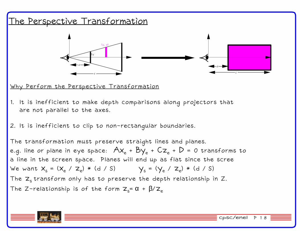
Why Perform the Perspective Transformation
1. It is inefficient to make depth comparisons along projectors thatare not parallel to the axes.
2. It is inefficient to clip to non−rectangular boundaries.
The transformation must preserve straight lines and planes.e.g. line or plane in eye space: Axe + Bye + Cze + D = 0 transforms toa line in the screen space. Planes will end up as flat since the screeWe want xs = (xe / ze) * (d / S) ys = (ye / ze) * (d / S)
The zs transform only has to preserve the depth relationship in Z.
The Z−relationship is of the form zs= α + β/ze

cpsc/enel P 1 9
zs is of the form α + β/ze we want the following conditions:
zs = 0 when ze = d
zs = ! when ze = F
0=α + β/d α= −β/d1=α + β/F α= 1−β/F
−β/d=1−β/F
β = −d/(1−d/F)α = 1/(1−d/F)
The Perspective Transformationcontinued
but zs = α + β/ze
substituting
zs = 1/(1−d/F) −d/(1−d/F)/ze
zs =(1−d/ze) (1−d/F)

cpsc/enel P 2 0
Viewbox and Perspective
x = xe/Sx
y = ye/Sy
z =
W = Ze/d
d(1−d/f)
Ze
(1−d/f)−1
Changing from Homogeneous coordinates to cartesian screen system
xs = =
ys =
zs =
Ze/d
(xe/Sx) xed
ZeSx
Ze/d
(ye/Sy) yed
ZeSy
(1−d/Ze)
(1−d/f)d(1−d/f)
Ze − d d/Ze =
d(1−d/f)1
(1−d/f)−1
1
d
1/Sx 0 0 0
0 1/Sy 0 0
0 0
0 0 0
x y z w = xe ye ze 1*

cpsc/enel P 2 1
Determining Z−Depth
What is the problem with linear interpolation method?Beware of large polygonsBeware of coincident polygons
Perspective transformation (viewbox tranformation)to normalize z to range [0:1]
Zs=1
Zs=0
∆Zs1
∆Zs2
Zs= 1 − D/Ze
1 − D/F
Ze=FZe=D ∆Ze ∆Ze