computer organization all computers perform ipos here, we concentrate on how ipos is carried out...
TRANSCRIPT

Computer Organization• All computers perform IPOS• Here, we concentrate on how
IPOS is carried out through the fetch-execute cycle
• This requires that we study– the structure of the components
in the computer– the function of those
components• how the CPU works• the role of memory• the role of I/O devices

The Structure of the Computer
To execute a program, the CPU performs the fetch-execute cycle
Fetch next instruction from memoryDecode the instructionExecute the instructionStore the result

The Bus• Address bus: – CPU sends address to memory or I/O subsystem– Address is the location of the item being moved
• Control bus: – CPU sends out commands to other devices
• read, write for memory• input, output, are you available for I/O devices
– Devices send signals back to the CPU such as interrupt
• Data bus: – Used to send data and program instructions
• from memory to the CPU• from the CPU to memory• between I/O device and the CPU • between I/O device and memory
– Size of data bus is often size of computer’s word

Memory Read & Write

Example: A Program• We use the following C program to better
understand the fetch-execute cycle#include <stdio.h> // input/output library void main( ) // start of the program{
int a, b, c; // use 3 integer variablesscanf(“%d”, &a); // input ascanf(“%d”, &b); // input bif(a < b) // compare a to b, if a is less then b c=a + b; // then set c to be their sumelse c=a - b; // otherwise set c to be their differenceprintf(“%d”, c); // output the result, c
}

Program in Assembly LanguageInput 33 // assume 33 is the keyboard, input a value from keyboardStore a // and store the value in the variable aInput 33 // repeat the input for bStore bLoad a // move a from memory to CPU, a location called the accumulatorSubt b // subtract b from the accumulator (accumulator = a – b)Jge else // if the result is greater than or equal to 0, go to location “else”Load a // otherwise, here we do the then clause, load a into accumulatorAdd b // add b (accumulator is now a + b)Store c // store the result (a + b) in cJump next // go to the location called next
else: Load a // here is the else clause, load a into the accumulator Subt b // subtract b (accumulator is now a – b)
Store c // store the result (a – b) into cnext: Load c // load c into the accumulator
Output 2049 // send the accumulator value to the output device 2049, assume // this is the monitor
Halt // end the program

Program in Machine Language
• Assembly language version of our C program is stored in the computer in machine language– The first four instructions might look like this:
1000100 0000000000000000000100001 – input (from keyboard)1000111 0010011000100101101010001 – store the datum in a1000100 0000000000000000000100001 – input (from keyboard)1000111 0010011000100101101010010 – store the datum in b
op code operand (datum)
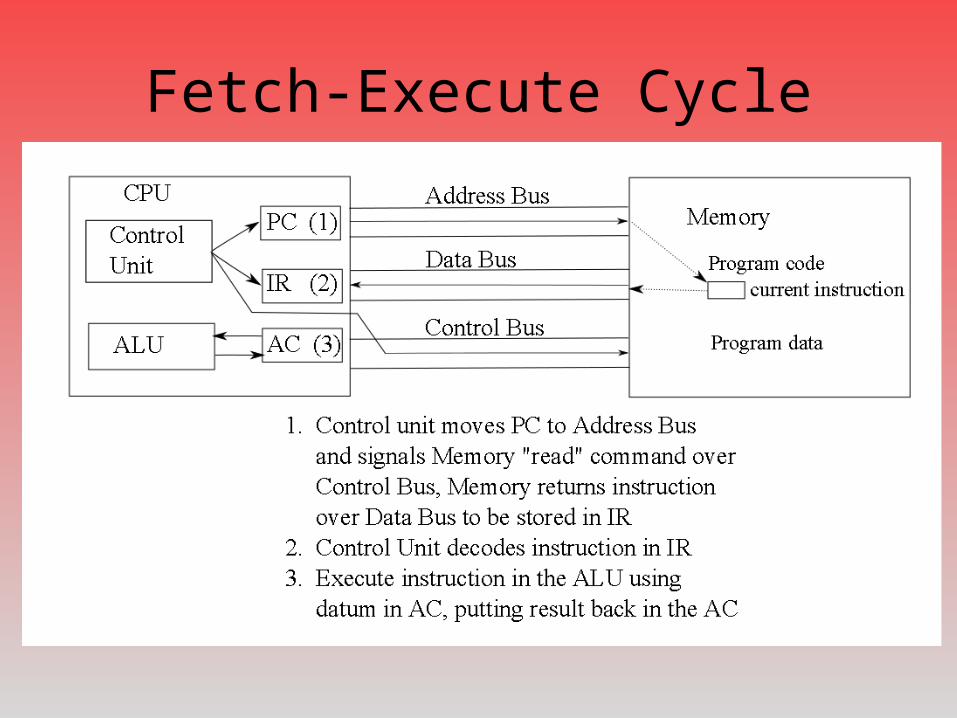
Fetch-Execute Cycle

Registers• Temporary storage in the CPU– Store values used during the fetch execute cycle– PC – program counter
• Memory location of next instruction, used during instruction fetch
– Data registers• To store temporary results during execution• Some computers have one, the accumulator (AC), others have several,
maybe dozens (eax, ebx, ecx, edx or R0, R1, R2, …, R31)
• IR – instruction register– Current instruction, used during decoding
• Status flags– To store information about the result of the previous ALU
operation• positive, negative, zero, even or odd parity, carry, overflow, interrupt

Fetch-Execute Cycle: Details• Fetch:
– PC stores address of next instruction– Fetch instruction at PC location– Increment PC– Instruction sent over data bus– Store instruction in IR
• Decode:– Decode opcode portion in IR– Determine operand(s) from instruction in
IR
• Execute:– Issue command(s) to proper circuits– Use data register(s)
• Store result– In AC (or data register), or memory
Input 33Store aInput 33Store bLoad aSubt bJge elseLoad aAdd bStore cJump next
else: Load a Subt b
Store cnext: Load c
Output 2049Halt

Fetch-Execute Cycle: Example• Assume our program starts at location 5,000,000– PC: 5,000,000– IR: -------
• Fetch instruction– PC: 5,000,000– IR: 1000100 0000000000000000000100001 – Increment PC to 5,000,001
• Decode instruction– Input operation (obtain input from keyboard)
• Execute:– Take input value from keyboard– Move to AC

Continued• Fetch instruction
– PC: 5,000,001– IR: 1000111 0010011000100101101010001– Increment PC to 5,000,002
• Decode instruction– Store datum to memory location
0010011000100101101010001 (memory location storing variable a)
• Execute:– Move datum from AC over data bus to memory location a
• NOTE: the next two instructions are almost identical except that the second input’s datum (from the third instruction) is sent to memory location b instead of a)

Continued• Load a
– Fetch instruction at 5,000,004– Increment PC to 5,000,005– Decode – load instruction, operand is a from
memory– Execute – loads datum at location a into AC
• Subt b– Fetch instruction at 5,000,005– Increment PC to 5,000,006– Decode – subtract instruction, operands are
AC register and b from memory– Execute – fetch b from memory, send AC and
b to subtracter circuit– Store result in AC– Set status flags as appropriate (negative,
positive, zero, carry, overflow)
Input 33Store aInput 33Store bLoad aSubt bJge elseLoad aAdd bStore cJump next
else: Load a Subt b
Store cnext: Load c
Output 2049Halt

Continued• Jge else –a branch instruction
– Fetch instruction at 5,000,006– Increment PC to 5,000,007– Decode instruction– Execute instruction – if positive or zero flag are set (1)
reset PC to 5,000,011 (branches to “else”) otherwise, end instruction
• Next instruction fetch is 5,000,007 or 5,000,011• Next few instructions executed depend on the
previous conditional branch– Either “Load a”, “Add b”, “Store c”, “Jump next” – Or “Load a”, “Subt b”, “Store c”
• Jump next – PC altered to 5,000,014 (location of “next”)
• Output 2049 – outputs value in AC to device 2049 (the monitor)
• Halt – ends the program
Input 33Store aInput 33Store bLoad aSubt bJge elseLoad aAdd bStore cJump next
else: Load a Subt b
Store cnext: Load c
Output 2049Halt

The Components of the CPU• Control Unit– Operates the
fetch-execute cycle
– Decodes instructions
– Sends out control signals
• Registers– Data register(s)– Control unit
registers
• Arithmetic-Logic Unit– Contains circuits to perform
arithmetic and logic operations• adder/subtracter• negater (convert + to -, - to +)• multiplier• divider• shifter• rotate• comparator
– Sets status flags

Microcode and System Clock• Each clock cycle, the control unit issues instructions to the
devices in the computer (1 part of the fetch-execute cycle, not a full instruction)
• These instructions are in the form of microcode– 1 bit per line on the control bus
• Example: instruction fetch– Move PC to address bus, Signal memory read, might look like
• 10000000000000100000000000000000000000000000000000
– 1 clock cycle = 1 microinstruction executed
• Fetch-execute cycle might have between 5 and 30 steps depending on architecture
• Clock speeds are given in GHz – 1 GHz = 1 billion clock cycles per second, or 1 clock cycle
executes in 1 billionth of a second (1 nanosecond)

Measuring CPU Performance• A faster clock does not necessarily mean a faster CPU
– CPU1 2.5 GHz, 12 stage fetch-execute cycle requiring 20 cycles to complete 1 instruction
– CPU2 1 GHz, 5 stage fetch-execute cycle requiring 8 cycles to complete 1 instruction
– CPU1 = 20 / 2.5 GHz = 8 nanoseconds / instruction– CPU2 = 8 / 1 GHz = 8 nanoseconds / instruction
• Other impacts of CPU performance include– Word size – size of datum being moved/processed– Cache performance (amount and usage of cache)– The program being run (some programs are slower than others)– How loaded the OS is– Virtual memory performance– Any parallel processing hardware?
• Best measure of CPU performance is to examine benchmark results

Role of Memory• Memory is referenced
every instruction– 1 instruction fetch– Possibly 1 or more data
accesses• data read as in Subt b• data write as in Store a
– In Intel x86 architecture, Add x, 5 involves 3 memory references• instruction fetch• load x for addition• store result in x
• Random Access Memory– There are several types of RAM– DRAM – “main memory”
• made of capacitors• requires timely refreshing• slow but very cheap
– SRAM – cache and registers• much faster• but more expensive
– ROM – read only memory• used to store boot program, BIOS• information permanent (cannot be
altered)• even more expensive
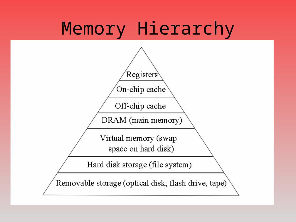
Memory Hierarchy

Using The Memory Hierarchy• The goal is to access only the highest levels of the hierarchy
– On a miss, move down to the next level• cache hit rates are as high as 98-99% • misses happen in 1 to 2 of every 100 accesses
– Bring item up to higher level– Bring its neighbors up as well in hopes of using them
• Lower levels act as “backstops”– On-chip caches are 32KB to 64KB today– Off-chip cache might be as large as 8MB– Main memory (DRAM) up to 8GB– Use hard disk space for memory’s backstop, known as swap space or
virtual memory
• When something is not in memory– Need to swap it from disk– May require discarding something from memory

The Role of I/O• I/O – input and output
– All I/O takes place in the I/O subsystem
– Devices connect to computer by expansion cards and ports
• Earliest form of I/O was punch cards (input) and printer (output) with magnetic tape used as intermediate storage– No direct interaction with
computer
• Today, we expect to interact directly with the computer– Pointing devices, keyboard,
microphone, monitor, speakers
• To improve interactivity, human computer interaction (HCI) combines– Computer science– Psychology– Design– Health
• And ergonomics– Reduce stress on the body
(repetitive stress injuries very prevalent, particularly Carpal Tunnel Syndrome)
– Improve accessibility for people with handicaps through larger monitors, speech recognition, Braille output devices
– See for instance Rehabilitation Act section 508
The Portable Computer• We no longer view the computer as a stationary device– Laptops, notebooks– Handheld devices
• Recent and near-future I/O devices– Wearables– Touch screens– Virtual reality interfaces– Sensor networks– Plug and play
• With wireless access we have– Interaction anywhere