computer network architectures and multimedia guy …leduc/cours/srm/srm-ch5.pdf · 1 ©from...
TRANSCRIPT
1
5: QoS Architectures 5-1 ©From Computer Networking, by Kurose&Ross
Computer Network Architectures and Multimedia
Guy Leduc
Chapter 5 Network Support for
Multimedia
Section 9.5 from Computer Networking: A Top Down Approach, 7th edition.
Jim Kurose, Keith Ross Addison-Wesley, April2016.
Also parts of chap. 9 and 13 from An Engineering Approach to Computer Networking - ATM
Networks, the Internet, and the Telephone Network.
S. Keshav Addison-Wesley Professional
Computing Series, 1997.
5: QoS Architectures 5-2 ©From Computer Networking, by Kurose&Ross
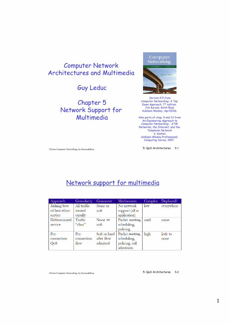
Network support for multimedia
marking,
marking,
or
2
5: QoS Architectures 5-3 ©From Computer Networking, by Kurose&Ross
Dimensioning best effort networks
❒ approach: deploy enough link capacity so that congestion doesn’t occur, multimedia traffic flows without delay or loss ❍ low complexity of network mechanisms (use current “best
effort” network) ❍ high bandwidth costs
❒ challenges: ❍ network dimensioning: how much bandwidth is “enough?” ❍ estimating network traffic demand: needed to determine how
much bandwidth is “enough” (for that much traffic)
5: QoS Architectures 5-4 ©From Computer Networking, by Kurose&Ross
Chapter 5 outline
5.1 Providing multiple classes of service - Principles - Scheduling Mechanisms - Shaping Mechanisms - Policing Mechanisms - Packet Drop Strategies - IETF Differentiated Services
5.2 Providing QoS guarantees - Principles - Bandwidth Guarantees - Delay Guarantees - Resource Reservation (RSVP signaling) - IETF Integrated Services

3
5: QoS Architectures 5-5 ©From Computer Networking, by Kurose&Ross
Providing Multiple Classes of Service ❒ thus far: making the best of best effort service
❍ “one-size fits all” service model ❒ alternative: multiple classes of service
❍ partition traffic into classes ❍ network treats different classes of traffic
differently (analogy: VIP service vs regular service)
0111
❒ granularity: differential service among multiple classes, not among individual flows
❒ history: ToS bits
5: QoS Architectures 5-6 ©From Computer Networking, by Kurose&Ross
Multiple classes of service: scenario
R1 R2 H1
H2
H3
H4 10 Mbps link R1 output
interface queue
4
5: QoS Architectures 5-7 ©From Computer Networking, by Kurose&Ross
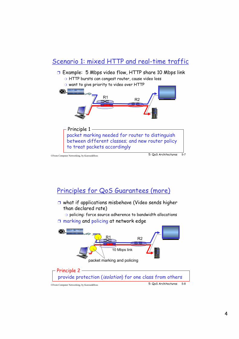
Scenario 1: mixed HTTP and real-time traffic ❒ Example: 5 Mbps video flow, HTTP share 10 Mbps link
❍ HTTP bursts can congest router, cause video loss ❍ want to give priority to video over HTTP
packet marking needed for router to distinguish between different classes; and new router policy to treat packets accordingly
Principle 1
R1 R2
5: QoS Architectures 5-8 ©From Computer Networking, by Kurose&Ross
Principles for QoS Guarantees (more) ❒ what if applications misbehave (Video sends higher
than declared rate) ❍ policing: force source adherence to bandwidth allocations
❒ marking and policing at network edge
provide protection (isolation) for one class from others Principle 2
R1 R2
10 Mbps link
packet marking and policing
5
5: QoS Architectures 5-9 ©From Computer Networking, by Kurose&Ross
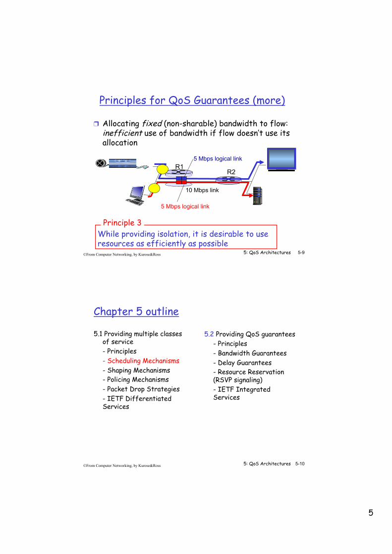
Principles for QoS Guarantees (more)
❒ Allocating fixed (non-sharable) bandwidth to flow: inefficient use of bandwidth if flow doesn’t use its allocation
While providing isolation, it is desirable to use resources as efficiently as possible
Principle 3
R1 R2
10 Mbps link
5 Mbps logical link
5 Mbps logical link
5: QoS Architectures 5-10 ©From Computer Networking, by Kurose&Ross
Chapter 5 outline
5.1 Providing multiple classes of service - Principles - Scheduling Mechanisms - Shaping Mechanisms - Policing Mechanisms - Packet Drop Strategies - IETF Differentiated Services
5.2 Providing QoS guarantees - Principles - Bandwidth Guarantees - Delay Guarantees - Resource Reservation (RSVP signaling) - IETF Integrated Services
6
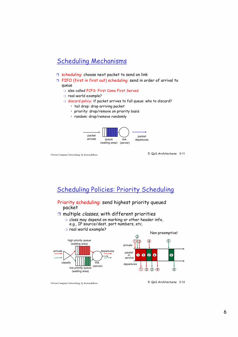
5: QoS Architectures 5-11 ©From Computer Networking, by Kurose&Ross
Scheduling Mechanisms
❒ scheduling: choose next packet to send on link ❒ FIFO (first in first out) scheduling: send in order of arrival to
queue ❍ also called FCFS: First Come First Served ❍ real-world example? ❍ discard policy: if packet arrives to full queue: who to discard?
• tail drop: drop arriving packet • priority: drop/remove on priority basis • random: drop/remove randomly
queue (waiting area)
packet arrivals
packet departures link
(server)
5: QoS Architectures 5-12 ©From Computer Networking, by Kurose&Ross
Scheduling Policies: Priority Scheduling
Priority scheduling: send highest priority queued packet
❒ multiple classes, with different priorities ❍ class may depend on marking or other header info,
e.g., IP source/dest, port numbers, etc. ❍ real world example?
Non preemptive!
high priority queue (waiting area)
low priority queue (waiting area)
arrivals
classify
departures
link (server)
1 3 2 4 5
5
5
2
2
1
1
3
3 4
4 arrivals
departures
packet in
service
7
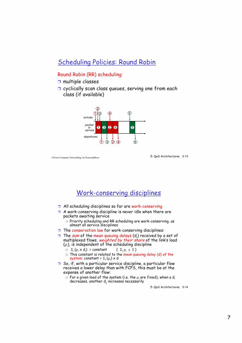
5: QoS Architectures 5-13 ©From Computer Networking, by Kurose&Ross
Scheduling Policies: Round Robin
Round Robin (RR) scheduling: ❒ multiple classes ❒ cyclically scan class queues, serving one from each
class (if available)
1 2 3 4 5
5
5
2
3
1
1
3
2 4
4 arrivals
departures
packet in
service
5: QoS Architectures 5-14 ©From Computer Networking, by Kurose&Ross
Work-conserving disciplines
❒ All scheduling disciplines so far are work-conserving ❒ A work-conserving discipline is never idle when there are
packets awaiting service ❍ Priority scheduling and RR scheduling are work-conserving, as
almost all service disciplines ❒ The conservation law for work-conserving disciplines: ❒ The sum of the mean queuing delays (di) received by a set of
multiplexed flows, weighted by their share of the link’s load (ρi), is independent of the scheduling discipline ❍ Σi (ρi x di) = constant ( Σi ρi ≤ 1 ) ❍ This constant is related to the mean queuing delay (d) of the
system: constant = Σi (ρi) x d ❒ So, if, with a particular service discipline, a particular flow
receives a lower delay than with FCFS, this must be at the expense of another flow: ❍ For a given load of the system (i.e. the ρi are fixed), when a di
decreases, another dj increases necessarily

8
5: QoS Architectures 5-15 ©From Computer Networking, by Kurose&Ross
Max-Min Fairness ❒ Scheduling discipline allocates a resource ❒ A resource allocation is max-min fair if and only if it is feasible and
any attempt to increase the allocation of any demand necessarily results in the decrease in the allocation of some other demand with an equal or smaller allocation
A B C A B C
Transfer half of excess
Unsatisfied demand
Resource�to be�
allocated=
Capacity
1/3 Excess
Still unsatisfied
Transfer excess
Demands
A B C
Unsatisfied demand
Max-Min Fairness (2)
❒ It protects small demands against heavy users ❍ each demand (flow/class) gets no more than what it wants
• small demands usually get it • big demands may not fully get it, but then all of them get the same
allocation ❒ Max-Min = “Maximize the Minimal” allocation
❍ firstly, the minimum data rate that a flow achieves is maximized; secondly, the second lowest data rate that a dataflow achieves is maximized, etc.
5: QoS Architectures 5-16 ©From Computer Networking, by Kurose&Ross
A B CCapacity
Unsatisfied
DemandsD
Satisfied
Draw demands so that areas are proportional to the demands with equal widths
The Max-Min Fair allocation is obtained by drawing an horizontal line so that Σ “blue areas” = “green area”
9
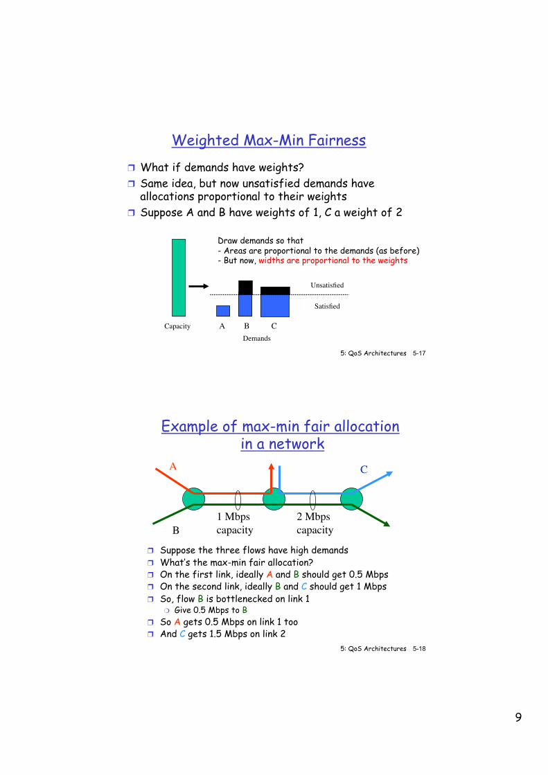
Weighted Max-Min Fairness ❒ What if demands have weights? ❒ Same idea, but now unsatisfied demands have
allocations proportional to their weights ❒ Suppose A and B have weights of 1, C a weight of 2
5: QoS Architectures 5-17 ©From Computer Networking, by Kurose&Ross
A B CCapacity
Unsatisfied
Demands
Satisfied
Draw demands so that - Areas are proportional to the demands (as before) - But now, widths are proportional to the weights
5: QoS Architectures 5-18 ©From Computer Networking, by Kurose&Ross
Example of max-min fair allocation in a network
❒ Suppose the three flows have high demands ❒ What’s the max-min fair allocation? ❒ On the first link, ideally A and B should get 0.5 Mbps ❒ On the second link, ideally B and C should get 1 Mbps ❒ So, flow B is bottlenecked on link 1
❍ Give 0.5 Mbps to B ❒ So A gets 0.5 Mbps on link 1 too ❒ And C gets 1.5 Mbps on link 2
A
B
C
1 Mbpscapacity
2 Mbpscapacity
10
5: QoS Architectures 5-19 ©From Computer Networking, by Kurose&Ross
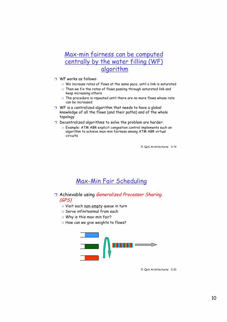
Max-min fairness can be computed centrally by the water filling (WF)
algorithm ❒ WF works as follows:
❍ We increase rates of flows at the same pace, until a link is saturated ❍ Then we fix the rates of flows passing through saturated link and
keep increasing others ❍ The procedure is repeated until there are no more flows whose rate
can be increased ❒ WF is a centralized algorithm that needs to have a global
knowledge of all the flows (and their paths) and of the whole topology
❒ Decentralized algorithms to solve the problem are harder: ❍ Example: ATM ABR explicit congestion control implements such an
algorithm to achieve max-min fairness among ATM ABR virtual circuits
5: QoS Architectures 5-20 ©From Computer Networking, by Kurose&Ross
Max-Min Fair Scheduling
❒ Achievable using Generalized Processor Sharing (GPS) ❍ Visit each non-empty queue in turn ❍ Serve infinitesimal from each ❍ Why is this max-min fair? ❍ How can we give weights to flows?
11
5: QoS Architectures 5-21 ©From Computer Networking, by Kurose&Ross
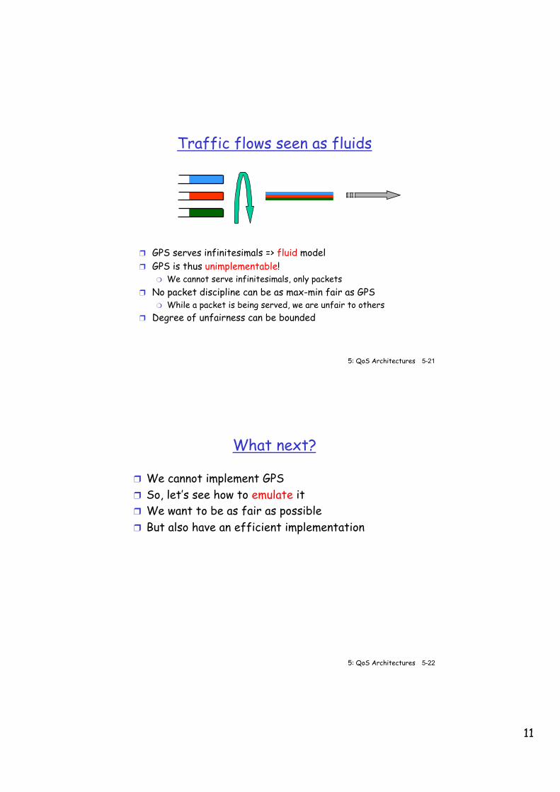
Traffic flows seen as fluids
❒ GPS serves infinitesimals => fluid model ❒ GPS is thus unimplementable!
❍ We cannot serve infinitesimals, only packets ❒ No packet discipline can be as max-min fair as GPS
❍ While a packet is being served, we are unfair to others ❒ Degree of unfairness can be bounded
5: QoS Architectures 5-22 ©From Computer Networking, by Kurose&Ross
What next?
❒ We cannot implement GPS ❒ So, let’s see how to emulate it ❒ We want to be as fair as possible ❒ But also have an efficient implementation
12
5: QoS Architectures 5-23 ©From Computer Networking, by Kurose&Ross
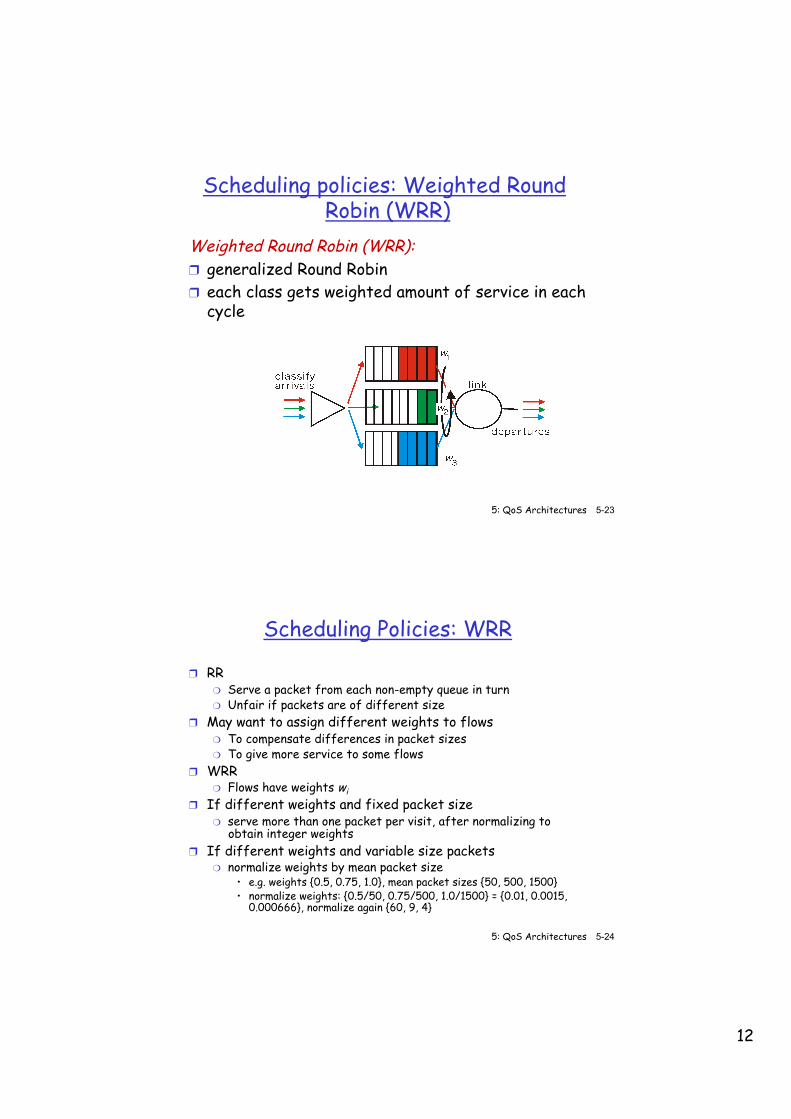
Weighted Round Robin (WRR): ❒ generalized Round Robin ❒ each class gets weighted amount of service in each
cycle
Scheduling policies: Weighted Round Robin (WRR)
5: QoS Architectures 5-24 ©From Computer Networking, by Kurose&Ross
Scheduling Policies: WRR
❒ RR ❍ Serve a packet from each non-empty queue in turn ❍ Unfair if packets are of different size
❒ May want to assign different weights to flows ❍ To compensate differences in packet sizes ❍ To give more service to some flows
❒ WRR ❍ Flows have weights wi
❒ If different weights and fixed packet size ❍ serve more than one packet per visit, after normalizing to
obtain integer weights ❒ If different weights and variable size packets
❍ normalize weights by mean packet size • e.g. weights {0.5, 0.75, 1.0}, mean packet sizes {50, 500, 1500} • normalize weights: {0.5/50, 0.75/500, 1.0/1500} = {0.01, 0.0015,
0.000666}, normalize again {60, 9, 4}
13
5: QoS Architectures 5-25 ©From Computer Networking, by Kurose&Ross
Problems with Weighted Round Robin
❒ Problem 1 : With variable size packets and different weights, need to know mean packet size in advance
❒ Problem 2: Can be unfair for long periods of time ❒ E.g.
❍ T3 trunk (45 Mbps) with 500 flows, each flow has mean packet length 500 bytes, 250 with weight 1, 250 with weight 10
❍ Each packet takes 500 * 8/45 Mbps = 88.8 microseconds ❍ Round time = (250 * 10 + 250 * 1) * 88.8 = 244.2 ms
5: QoS Architectures 5-26 ©From Computer Networking, by Kurose&Ross
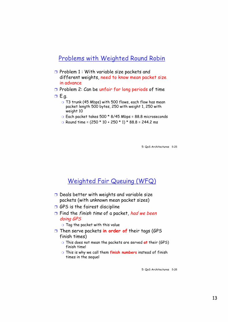
Weighted Fair Queuing (WFQ)
❒ Deals better with weights and variable size packets (with unknown mean packet sizes)
❒ GPS is the fairest discipline ❒ Find the finish time of a packet, had we been
doing GPS ❍ Tag the packet with this value
❒ Then serve packets in order of their tags (GPS finish times) ❍ This does not mean the packets are served at their (GPS)
finish time! ❍ This is why we call them finish numbers instead of finish
times in the sequel
14
5: QoS Architectures 5-27 ©From Computer Networking, by Kurose&Ross
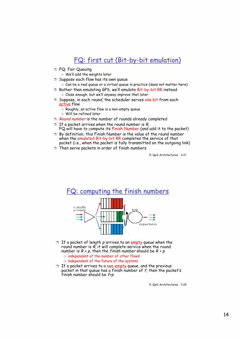
FQ: first cut (Bit-by-bit emulation) ❒ FQ: Fair Queuing
❍ We’ll add the weights later ❒ Suppose each flow has its own queue
❍ Can be a real queue or a virtual queue in practice (does not matter here) ❒ Rather than emulating GPS, we’ll emulate Bit-by-bit RR instead
❍ Close enough, but we’ll anyway improve that later ❒ Suppose, in each round, the scheduler serves one bit from each
active flow ❍ Roughly, an active flow is a non-empty queue ❍ Will be refined later
❒ Round number is the number of rounds already completed ❒ If a packet arrives when the round number is R,
FQ will have to compute its Finish Number (and add it to the packet) ❒ By definition, this Finish Number is the value of the round number
when the emulated Bit-by-bit RR completes the service of that packet (i.e., when the packet is fully transmitted on the outgoing link)
❒ Then serve packets in order of finish numbers
FQ: computing the finish numbers
❒ If a packet of length p arrives to an empty queue when the round number is R, it will complete service when the round number is R + p, then the finish number should be R + p ❍ independent of the number of other flows! ❍ independent of the future of the system!
❒ If a packet arrives to a non-empty queue, and the previous packet in that queue has a finish number of f, then the packet’s finish number should be f+p
5: QoS Architectures 5-28 ©From Computer Networking, by Kurose&Ross
15
5: QoS Architectures 5-29 ©From Computer Networking, by Kurose&Ross
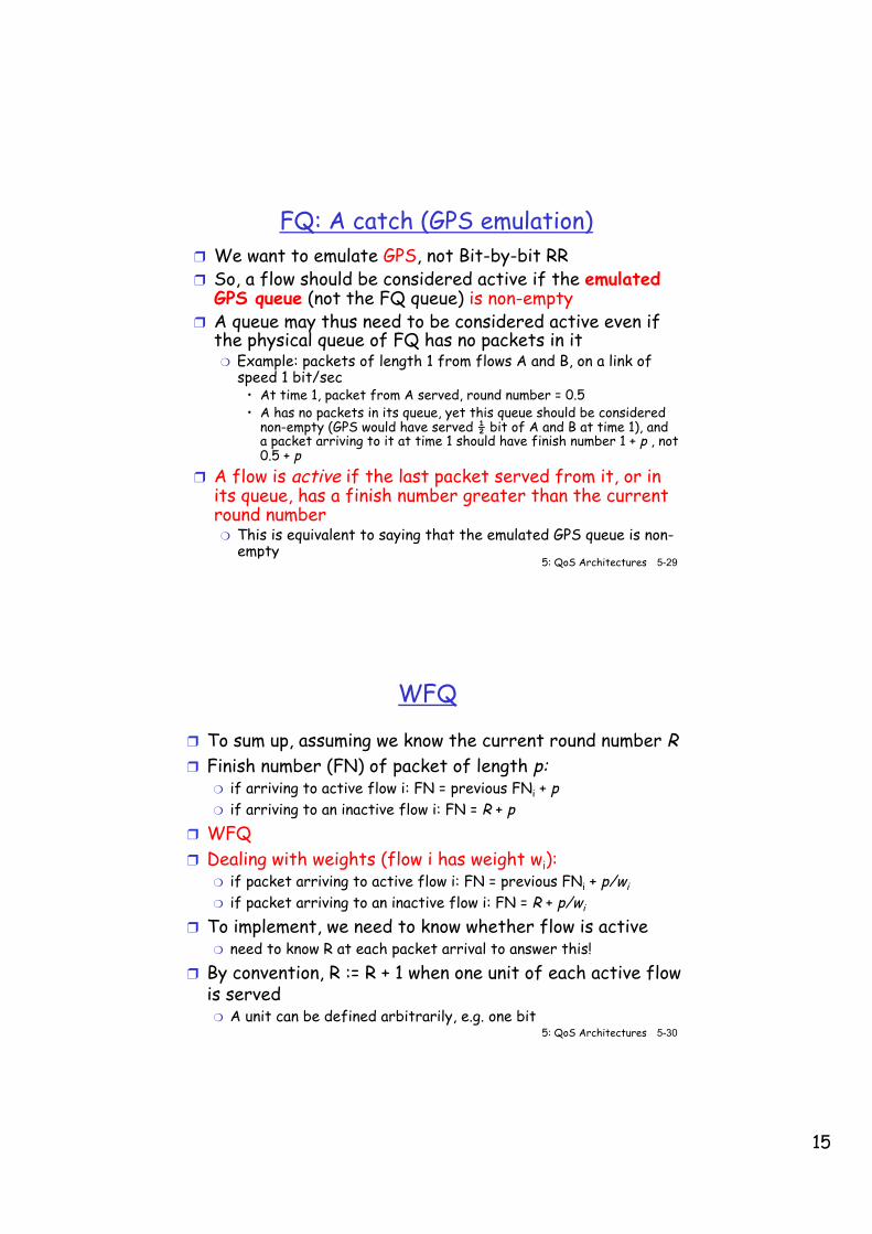
FQ: A catch (GPS emulation) ❒ We want to emulate GPS, not Bit-by-bit RR ❒ So, a flow should be considered active if the emulated
GPS queue (not the FQ queue) is non-empty ❒ A queue may thus need to be considered active even if
the physical queue of FQ has no packets in it ❍ Example: packets of length 1 from flows A and B, on a link of
speed 1 bit/sec • At time 1, packet from A served, round number = 0.5 • A has no packets in its queue, yet this queue should be considered
non-empty (GPS would have served ½ bit of A and B at time 1), and a packet arriving to it at time 1 should have finish number 1 + p , not 0.5 + p
❒ A flow is active if the last packet served from it, or in its queue, has a finish number greater than the current round number ❍ This is equivalent to saying that the emulated GPS queue is non-
empty
5: QoS Architectures 5-30 ©From Computer Networking, by Kurose&Ross
WFQ
❒ To sum up, assuming we know the current round number R ❒ Finish number (FN) of packet of length p:
❍ if arriving to active flow i: FN = previous FNi + p ❍ if arriving to an inactive flow i: FN = R + p
❒ WFQ ❒ Dealing with weights (flow i has weight wi):
❍ if packet arriving to active flow i: FN = previous FNi + p/wi ❍ if packet arriving to an inactive flow i: FN = R + p/wi
❒ To implement, we need to know whether flow is active ❍ need to know R at each packet arrival to answer this!
❒ By convention, R := R + 1 when one unit of each active flow is served ❍ A unit can be defined arbitrarily, e.g. one bit
16
5: QoS Architectures 5-31 ©From Computer Networking, by Kurose&Ross
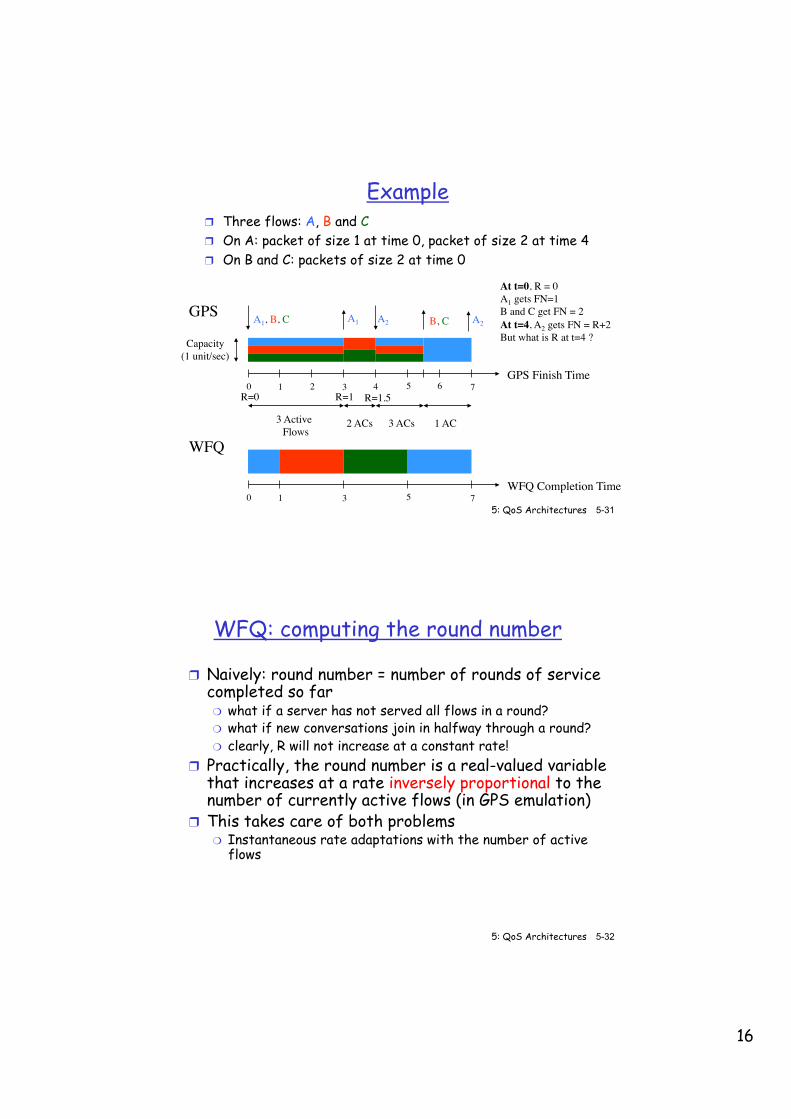
Example ❒ Three flows: A, B and C ❒ On A: packet of size 1 at time 0, packet of size 2 at time 4 ❒ On B and C: packets of size 2 at time 0
0 1 2 3 4 5 6 7GPS Finish Time
Capacity(1 unit/sec)
3 Active� Flows
2 ACs 3 ACs 1 AC
A1, B, C A2A1 B, C A2GPS
WFQ
0 1 3 5 7WFQ Completion Time
At t=0, R = 0A1 gets FN=1B and C get FN = 2At t=4, A2 gets FN = R+2But what is R at t=4 ?
R=0 R=1 R=1.5
5: QoS Architectures 5-32 ©From Computer Networking, by Kurose&Ross
WFQ: computing the round number
❒ Naively: round number = number of rounds of service completed so far ❍ what if a server has not served all flows in a round? ❍ what if new conversations join in halfway through a round? ❍ clearly, R will not increase at a constant rate!
❒ Practically, the round number is a real-valued variable that increases at a rate inversely proportional to the number of currently active flows (in GPS emulation)
❒ This takes care of both problems ❍ Instantaneous rate adaptations with the number of active
flows
17
5: QoS Architectures 5-33 ©From Computer Networking, by Kurose&Ross
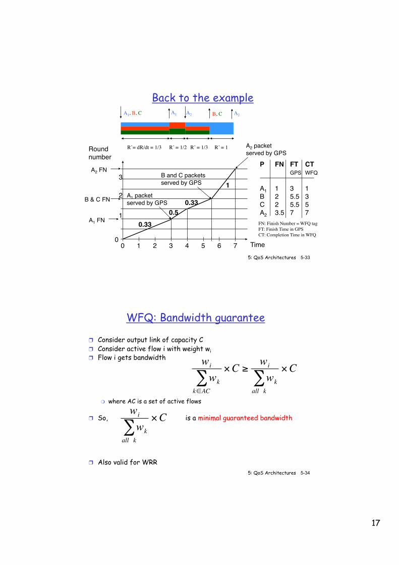
Back to the example
Roundnumber
3
2
1
00 1 2 3 4 5 6 7
0.330.5
0.33
1
Time
A1 packetserved by GPS
B and C packetsserved by GPS
A2 packetserved by GPS
A2 FN
A1 FN
B & C FN
P FN FT CTGPS WFQ
A1 1 3 1B 2 5.5 3C 2 5.5 5A2 3.5 7 7
A1, B, C A2A1 B, C A2
R’= dR/dt = 1/3 R’ = 1/2 R’ = 1/3 R’ = 1
FN: Finish Number = WFQ tagFT: Finish Time in GPSCT: Completion Time in WFQ
5: QoS Architectures 5-34 ©From Computer Networking, by Kurose&Ross
WFQ: Bandwidth guarantee
❒ Consider output link of capacity C ❒ Consider active flow i with weight wi ❒ Flow i gets bandwidth
❍ where AC is a set of active flows
❒ So, is a minimal guaranteed bandwidth
❒ Also valid for WRR
€
wi
wkall k∑
×C€
wi
wkk∈AC∑
×C ≥wi
wkall k∑
×C
18
5: QoS Architectures 5-35 ©From Computer Networking, by Kurose&Ross
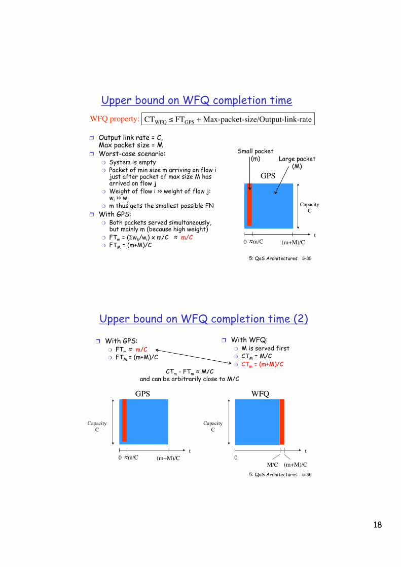
Upper bound on WFQ completion time
❒ Output link rate = C, Max packet size = M
❒ Worst-case scenario: ❍ System is empty ❍ Packet of min size m arriving on flow i
just after packet of max size M has arrived on flow j
❍ Weight of flow i >> weight of flow j: wi >> wj
❍ m thus gets the smallest possible FN ❒ With GPS:
❍ Both packets served simultaneously, but mainly m (because high weight)
❍ FTm = (Σwk/wi) x m/C ≈ m/C ❍ FTM = (m+M)/C
CTWFQ ≤ FTGPS + Max-packet-size/Output-link-rateWFQ property:
GPS
0 ≈m/C (m+M)/C
Capacity�C
t
Small packet (m) Large packet
(M)
Upper bound on WFQ completion time (2)
❒ With GPS: ❍ FTm ≈ m/C ❍ FTM = (m+M)/C
5: QoS Architectures 5-36 ©From Computer Networking, by Kurose&Ross
GPS
0 ≈m/C (m+M)/C
Capacity�C
t
WFQ
0M/C (m+M)/C
Capacity�C
t
❒ With WFQ: ❍ M is served first ❍ CTM = M/C ❍ CTm = (m+M)/C
CTm - FTm ≈ M/C and can be arbitrarily close to M/C
19
5: QoS Architectures 5-37 ©From Computer Networking, by Kurose&Ross
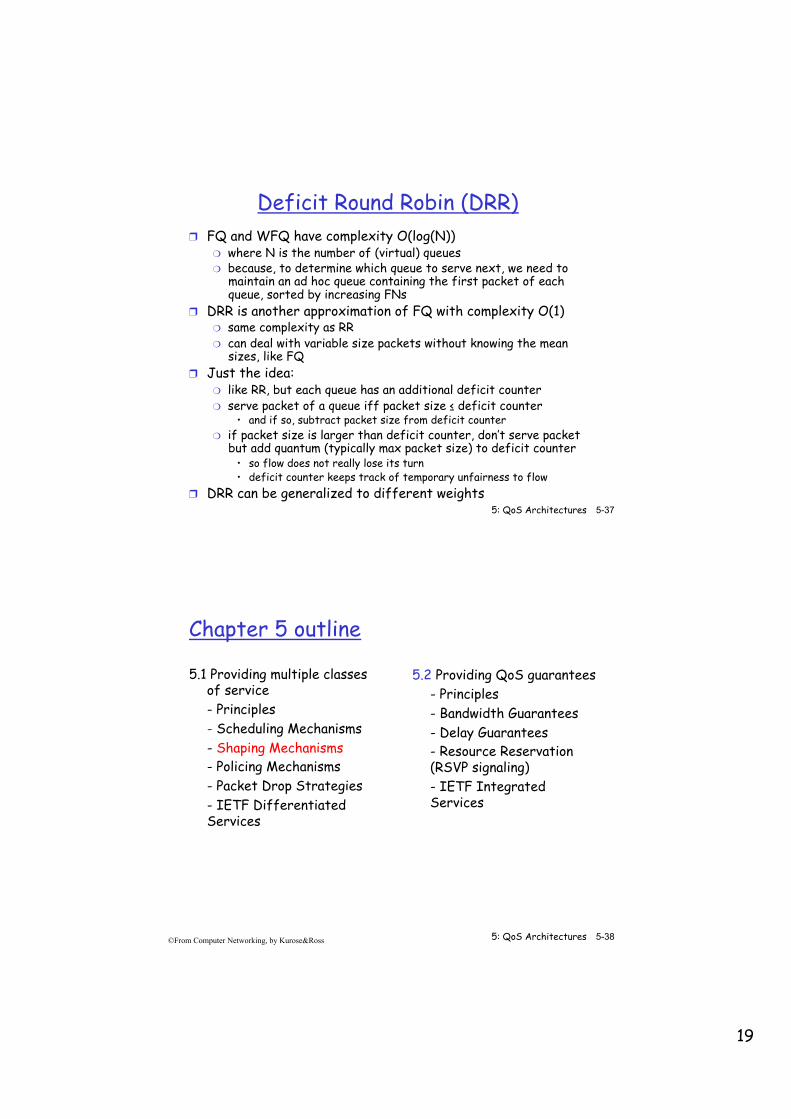
Deficit Round Robin (DRR) ❒ FQ and WFQ have complexity O(log(N))
❍ where N is the number of (virtual) queues ❍ because, to determine which queue to serve next, we need to
maintain an ad hoc queue containing the first packet of each queue, sorted by increasing FNs
❒ DRR is another approximation of FQ with complexity O(1) ❍ same complexity as RR ❍ can deal with variable size packets without knowing the mean
sizes, like FQ ❒ Just the idea:
❍ like RR, but each queue has an additional deficit counter ❍ serve packet of a queue iff packet size ≤ deficit counter
• and if so, subtract packet size from deficit counter ❍ if packet size is larger than deficit counter, don’t serve packet
but add quantum (typically max packet size) to deficit counter • so flow does not really lose its turn • deficit counter keeps track of temporary unfairness to flow
❒ DRR can be generalized to different weights
5: QoS Architectures 5-38 ©From Computer Networking, by Kurose&Ross
Chapter 5 outline
5.1 Providing multiple classes of service - Principles - Scheduling Mechanisms - Shaping Mechanisms - Policing Mechanisms - Packet Drop Strategies - IETF Differentiated Services
5.2 Providing QoS guarantees - Principles - Bandwidth Guarantees - Delay Guarantees - Resource Reservation (RSVP signaling) - IETF Integrated Services

20
5: QoS Architectures 5-39 ©From Computer Networking, by Kurose&Ross
Shaping Mechanisms
Goal: limit traffic to not exceed declared parameters Three common-used criteria: ❒ (Long term) Average Rate: how many packets can be
sent per unit time (in the long run) ❍ crucial question: what is the interval length: ❍ 100 packets per sec or 6000 packets per min have same
average! ❒ Peak Rate:
❍ e.g., 6000 packets per min. avg.; 1500 packets per sec. peak rate
❒ (Max.) Burst Size: max. number of packets sent consecutively at the peak rate
5: QoS Architectures 5-40 ©From Computer Networking, by Kurose&Ross
Peak Rate Shaping
Computer
Output link
Interfacecontaininga leakybucket
Leaky Bucket
21
5: QoS Architectures 5-41 ©From Computer Networking, by Kurose&Ross
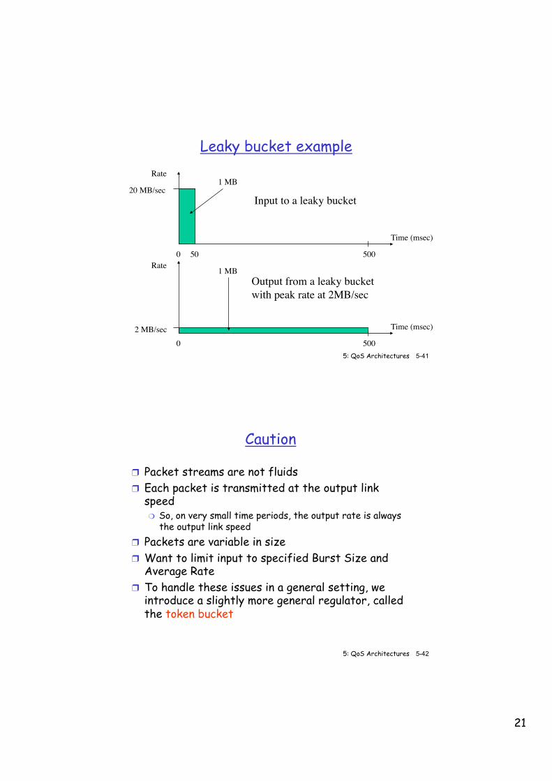
Leaky bucket example
Time (msec)
0 50
20 MB/sec
500
Rate1 MB
Time (msec)
02 MB/sec
500
Rate 1 MB
Input to a leaky bucket
Output from a leaky bucketwith peak rate at 2MB/sec
5: QoS Architectures 5-42 ©From Computer Networking, by Kurose&Ross
Caution
❒ Packet streams are not fluids ❒ Each packet is transmitted at the output link
speed ❍ So, on very small time periods, the output rate is always
the output link speed ❒ Packets are variable in size ❒ Want to limit input to specified Burst Size and
Average Rate ❒ To handle these issues in a general setting, we
introduce a slightly more general regulator, called the token bucket
22
5: QoS Architectures 5-43 ©From Computer Networking, by Kurose&Ross
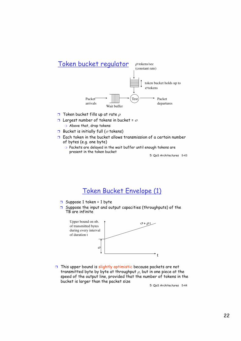
Token bucket regulator
❒ Token bucket fills up at rate ρ ❒ Largest number of tokens in bucket = σ
❍ Above that, drop tokens ❒ Bucket is initially full (σ tokens) ❒ Each token in the bucket allows transmission of a certain number
of bytes (e.g. one byte) ❍ Packets are delayed in the wait buffer until enough tokens are
present in the token bucket
ρ tokens/sec(constant rate)
token bucket holds up to σ tokens
Wait buffer
Test Packet�departures
Packet �arrivals
5: QoS Architectures 5-44 ©From Computer Networking, by Kurose&Ross
Token Bucket Envelope (1) ❒ Suppose 1 token = 1 byte ❒ Suppose the input and output capacities (throughputs) of the
TB are infinite
t
Upper bound on nb.of transmitted bytesduring every intervalof duration t
σ
σ + ρ t
❒ This upper bound is slightly optimistic because packets are not transmitted byte by byte at throughput ρ, but in one piece at the speed of the output line, provided that the number of tokens in the bucket is larger than the packet size
23
5: QoS Architectures 5-45 ©From Computer Networking, by Kurose&Ross
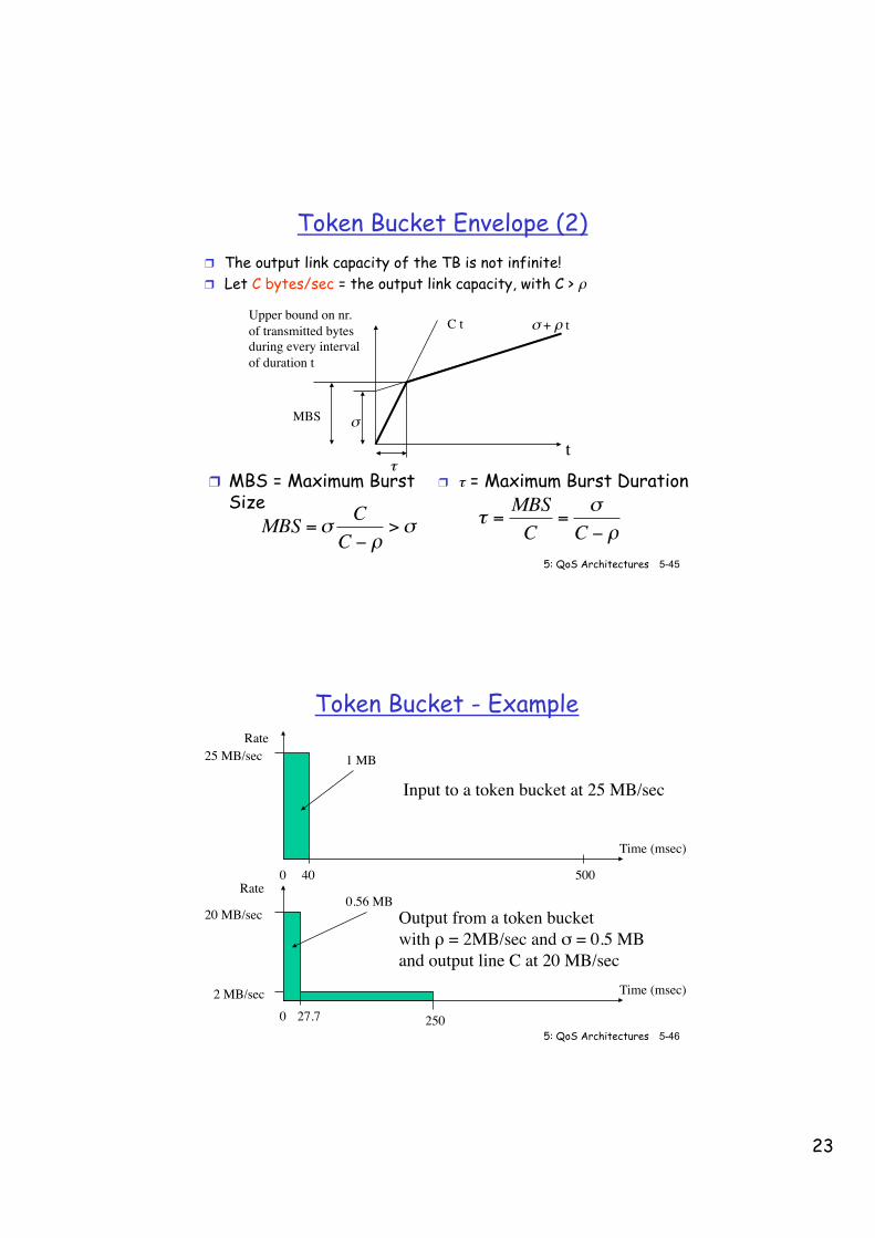
Token Bucket Envelope (2) ❒ The output link capacity of the TB is not infinite! ❒ Let C bytes/sec = the output link capacity, with C > ρ
t
Upper bound on nr.of transmitted bytesduring every intervalof duration t
σ
σ + ρ tC t
MBS
❒ MBS = Maximum Burst Size
€
MBS =σC
C − ρ>σ
τ❒ τ = Maximum Burst Duration
€
τ =MBSC
=σ
C − ρ
5: QoS Architectures 5-46 ©From Computer Networking, by Kurose&Ross
Token Bucket - Example
Time (msec)
0 40
25 MB/sec
500
Rate1 MB
Time (msec)
02 MB/sec
250
Rate0.56 MB
Input to a token bucket at 25 MB/sec
Output from a token bucketwith ρ = 2MB/sec and σ = 0.5 MBand output line C at 20 MB/sec
27.7
20 MB/sec
24
5: QoS Architectures 5-47 ©From Computer Networking, by Kurose&Ross
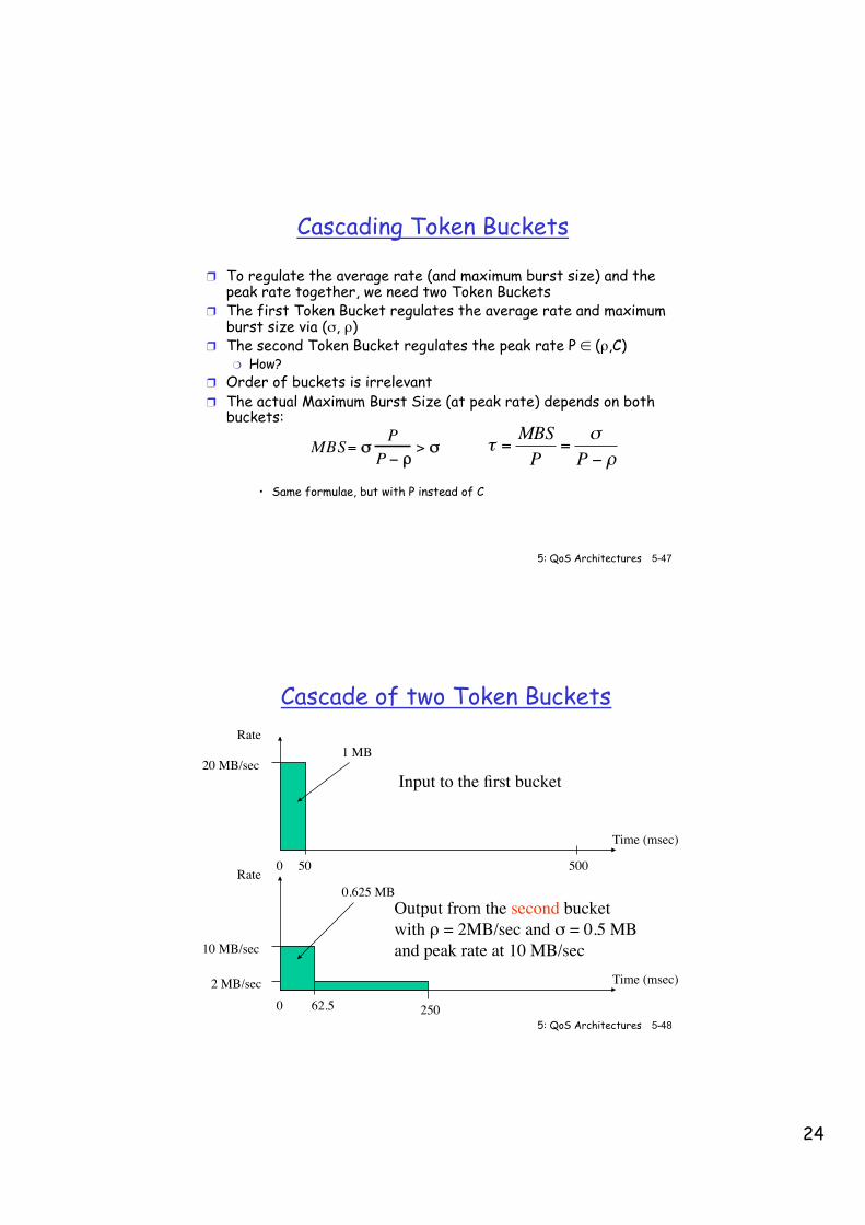
Cascading Token Buckets
❒ To regulate the average rate (and maximum burst size) and the peak rate together, we need two Token Buckets
❒ The first Token Bucket regulates the average rate and maximum burst size via (σ, ρ)
❒ The second Token Bucket regulates the peak rate P ∈ (ρ,C) ❍ How?
❒ Order of buckets is irrelevant ❒ The actual Maximum Burst Size (at peak rate) depends on both
buckets:
• Same formulae, but with P instead of C
MBS= σP
P − ρ> σ
€
τ =MBSP
=σ
P − ρ
5: QoS Architectures 5-48 ©From Computer Networking, by Kurose&Ross
Cascade of two Token Buckets
Time (msec)
0 50
20 MB/sec
500
Rate1 MB
Time (msec)
02 MB/sec
250
Rate0.625 MB
Input to the first bucket
Output from the second bucketwith ρ = 2MB/sec and σ = 0.5 MBand peak rate at 10 MB/sec
62.5
10 MB/sec
25
5: QoS Architectures 5-49 ©From Computer Networking, by Kurose&Ross
Chapter 5 outline
5.1 Providing multiple classes of service - Principles - Scheduling Mechanisms - Shaping Mechanisms - Policing Mechanisms - Packet Drop Strategies - IETF Differentiated Services
5.2 Providing QoS guarantees - Principles - Bandwidth Guarantees - Delay Guarantees - Resource Reservation (RSVP signaling) - IETF Integrated Services
5: QoS Architectures 5-50 ©From Computer Networking, by Kurose&Ross
Traffic Shaping and Policing
❒ Shaping and Policing are similar functions ❒ Shaping means that the offered load will remain
within a given envelope defined by a traffic descriptor ❍ It can be performed by the source or some router
❒ Policing is the dual of shaping ❒ Policing means checking that the offered load
remains within a given envelope (as announced) ❍ It is typically performed at the entry point (ingress) of a
network

26
5: QoS Architectures 5-51 ©From Computer Networking, by Kurose&Ross
Policing ❒ Policing can again be achieved with a Token Bucket ❒ Non conforming packets can be dropped or marked ❒ Note: no data buffer here, packets are not delayed
ρ tokens/sec(constant rate)
σ tokens max
TestAccept packet in network(and remove L tokensfrom bucket)
Incoming packet of size L
Tokenbucket
Bucket contains at least L tokens
Bucket contains less than L tokens Drop or mark packet
(and leave the bucket“as is”)
Suppose one token = 1 byte
5: QoS Architectures 5-52 ©From Computer Networking, by Kurose&Ross
Policing according to several criteria
❒ Typically, peak rate and average rate + burst limit ❒ Use a cascade of Token Buckets
❍ Example: ❍ The first TB drops packets that exceed the peak rate ❍ The second TB drops packets that exceed the (average rate +
maximum burst size) ❒ Would work similarly with marking instead of dropping
❍ If peak rate is exceeded, the first TB marks the packet ❍ If the (average rate + maximum burst size) is exceeded, the
second TB marks the packet ❒ Here we can even discriminate the two cases by
marking packets differently, say with different colors ❍ Useful when more than two drop precedence levels are used in
the network
27
5: QoS Architectures 5-53 ©From Computer Networking, by Kurose&Ross
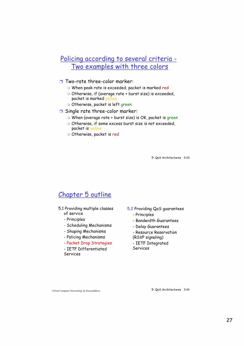
Policing according to several criteria - Two examples with three colors
❒ Two-rate three-color marker: ❍ When peak rate is exceeded, packet is marked red ❍ Otherwise, if (average rate + burst size) is exceeded,
packet is marked yellow ❍ Otherwise, packet is left green
❒ Single rate three-color marker: ❍ When (average rate + burst size) is OK, packet is green ❍ Otherwise, if some excess burst size is not exceeded,
packet is yellow ❍ Otherwise, packet is red
5: QoS Architectures 5-54 ©From Computer Networking, by Kurose&Ross
Chapter 5 outline
5.1 Providing multiple classes of service - Principles - Scheduling Mechanisms - Shaping Mechanisms - Policing Mechanisms - Packet Drop Strategies - IETF Differentiated Services
5.2 Providing QoS guarantees - Principles - Bandwidth Guarantees - Delay Guarantees - Resource Reservation (RSVP signaling) - IETF Integrated Services
28
5: QoS Architectures 5-55 ©From Computer Networking, by Kurose&Ross
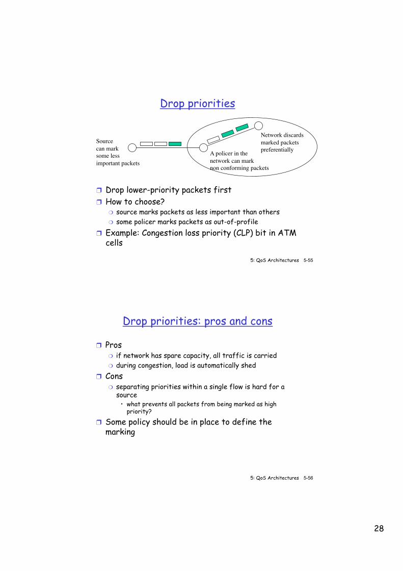
Drop priorities
❒ Drop lower-priority packets first ❒ How to choose?
❍ source marks packets as less important than others ❍ some policer marks packets as out-of-profile
❒ Example: Congestion loss priority (CLP) bit in ATM cells
Sourcecan marksome lessimportant packets
Network discardsmarked packetspreferentiallyA policer in the
network can mark non conforming packets
5: QoS Architectures 5-56 ©From Computer Networking, by Kurose&Ross
Drop priorities: pros and cons
❒ Pros ❍ if network has spare capacity, all traffic is carried ❍ during congestion, load is automatically shed
❒ Cons ❍ separating priorities within a single flow is hard for a
source • what prevents all packets from being marked as high
priority?
❒ Some policy should be in place to define the marking
29
5: QoS Architectures 5-57 ©From Computer Networking, by Kurose&Ross
Drop priority (contd.)
❒ Ideally: if you drop any portion of a fragmented packet, drop the rest of the fragments ❍ A single dropped fragment means that the whole packet
has to be retransmitted anyway ❍ Can’t do it on Internet because no packet state in
routers! ❒ Ideally: drop packets from ‘nearby’ hosts first
❍ Because they have used the least network resources ❍ Can’t do it with IP because hop count (TTL) decreases
and the initial value is not known in general!
5: QoS Architectures 5-58 ©From Computer Networking, by Kurose&Ross
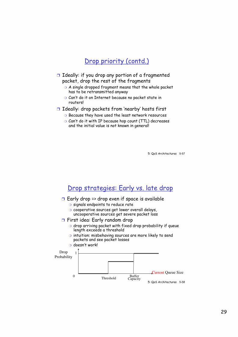
Drop strategies: Early vs. late drop ❒ Early drop => drop even if space is available
❍ signals endpoints to reduce rate ❍ cooperative sources get lower overall delays,
uncooperative sources get severe packet loss ❒ First idea: Early random drop
❍ drop arriving packet with fixed drop probability if queue length exceeds a threshold
❍ intuition: misbehaving sources are more likely to send packets and see packet losses
❍ doesn’t work!
Current Queue Size
DropProbability
BufferCapacityThreshold
1
0
30
5: QoS Architectures 5-59 ©From Computer Networking, by Kurose&Ross
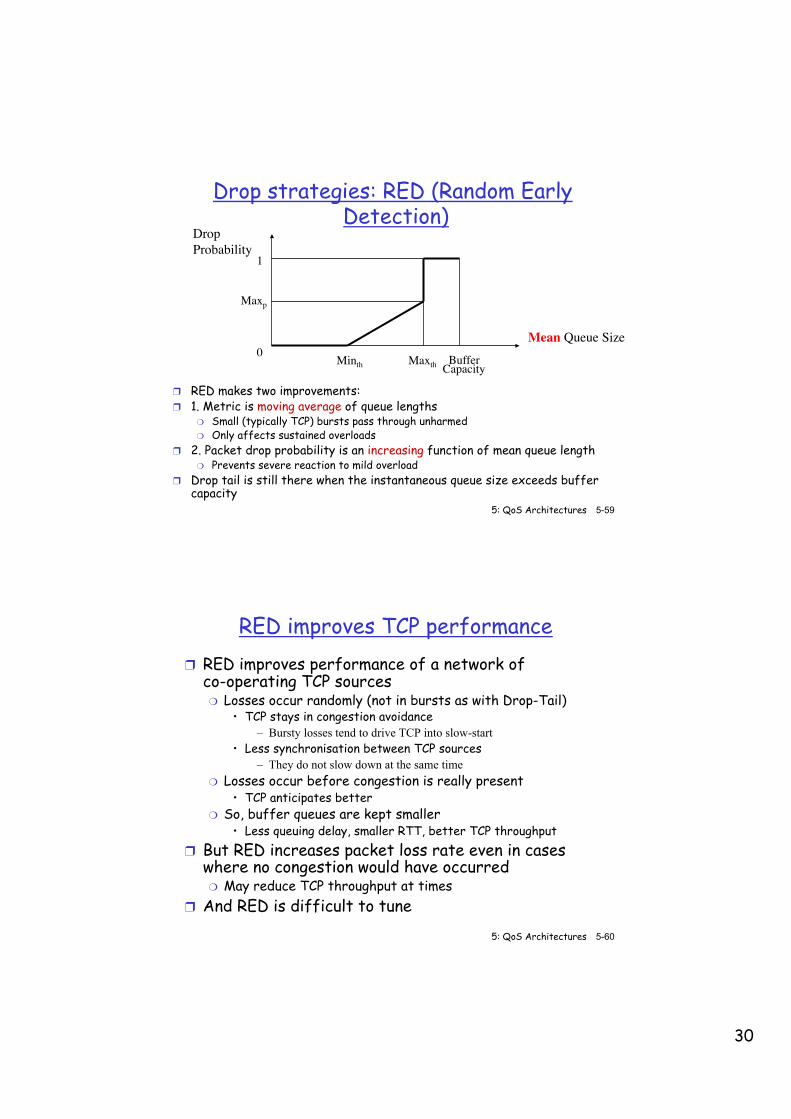
Drop strategies: RED (Random Early Detection)
❒ RED makes two improvements: ❒ 1. Metric is moving average of queue lengths
❍ Small (typically TCP) bursts pass through unharmed ❍ Only affects sustained overloads
❒ 2. Packet drop probability is an increasing function of mean queue length ❍ Prevents severe reaction to mild overload
❒ Drop tail is still there when the instantaneous queue size exceeds buffer capacity
Mean Queue Size
DropProbability
BufferCapacity
Minth Maxth
1
0
Maxp
5: QoS Architectures 5-60 ©From Computer Networking, by Kurose&Ross
RED improves TCP performance ❒ RED improves performance of a network of
co-operating TCP sources ❍ Losses occur randomly (not in bursts as with Drop-Tail)
• TCP stays in congestion avoidance – Bursty losses tend to drive TCP into slow-start
• Less synchronisation between TCP sources – They do not slow down at the same time
❍ Losses occur before congestion is really present • TCP anticipates better
❍ So, buffer queues are kept smaller • Less queuing delay, smaller RTT, better TCP throughput
❒ But RED increases packet loss rate even in cases where no congestion would have occurred ❍ May reduce TCP throughput at times
❒ And RED is difficult to tune
31
5: QoS Architectures 5-61 ©From Computer Networking, by Kurose&Ross
RED variant - ECN
❒ ECN = Early Congestion Notification ❒ RED can mark (a bit in) packets instead of
dropping them ❍ Allows destination to detect network congestion state ❍ Allows sources to detect it too and without losses, if the
destination copies the marks in acknowledgements • But IP is connectionless • Needs to do it in TCP ACKs • TCP source has to be modified to interpret marks • This TCP variant is called TCP ECN
5: QoS Architectures 5-62 ©From Computer Networking, by Kurose&Ross
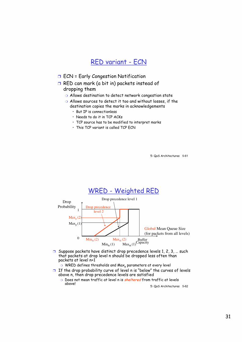
WRED - Weighted RED
❒ Suppose packets have distinct drop precedence levels 1, 2, 3, … such that packets at drop level n should be dropped less often than packets at level n+1 ❍ WRED defines thresholds and Maxp parameters at every level
❒ If the drop probability curve of level n is “below” the curves of levels above n, then drop precedence levels are satisfied ❍ Does not mean traffic at level n is sheltered from traffic at levels
above!
Global Mean Queue Size(for packets from all levels)
DropProbability
BufferCapacityMinth (1) Maxth (1)
1
0 Minth (2) Maxth (2)
Drop precedence level 2
Drop precedence level 1
Maxp (1)Maxp (2)
32
5: QoS Architectures 5-63 ©From Computer Networking, by Kurose&Ross
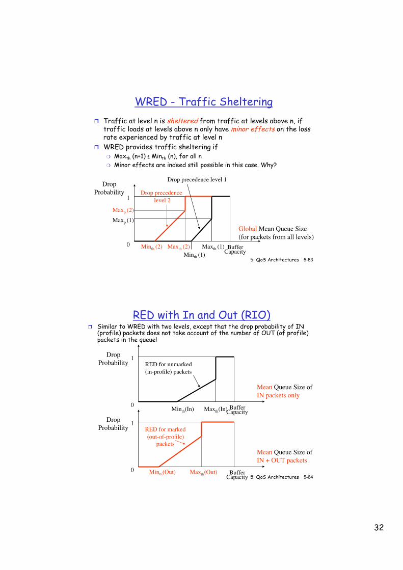
WRED - Traffic Sheltering ❒ Traffic at level n is sheltered from traffic at levels above n, if
traffic loads at levels above n only have minor effects on the loss rate experienced by traffic at level n
❒ WRED provides traffic sheltering if ❍ Maxth (n+1) ≤ Minth (n), for all n ❍ Minor effects are indeed still possible in this case. Why?
Global Mean Queue Size(for packets from all levels)
DropProbability
BufferCapacityMinth (1)
Maxth (1)
1
0 Minth (2) Maxth (2)
Drop precedence level 2
Drop precedence level 1
Maxp (1)Maxp (2)
5: QoS Architectures 5-64 ©From Computer Networking, by Kurose&Ross
RED with In and Out (RIO) ❒ Similar to WRED with two levels, except that the drop probability of IN
(profile) packets does not take account of the number of OUT (of profile) packets in the queue!
Mean Queue Size ofIN packets only
DropProbability
BufferCapacityMinth(In) Maxth(In)
1
0
RED for unmarked(in-profile) packets
Mean Queue Size ofIN + OUT packets
DropProbability
BufferCapacity
1
0 Minth(Out) Maxth(Out)
RED for marked(out-of-profile)
packets

33
5: QoS Architectures 5-65 ©From Computer Networking, by Kurose&Ross
RED with In and Out (RIO)
❒ With the same parameter settings, RIO is better than a WRED with 2 levels in protecting In-profile packets from Out-of-profile packets ❍ Why?
❒ With RIO, the drop rate of In-profile packets does not depend on the Out-of-profile packets in the system, except in exceptional circumstances when the buffer overflows ❍ So RIO provides traffic sheltering
❒ If Maxth(Out) ≤ Minth(In), then In-profile packets can only be dropped iff all Out-of-profile packets are already being dropped ❍ Why?
❒ As a particular case, one might have ❍ Drop Tail on in-profile packets ❍ RED on out-of-profile packets only
❒ At high loads, both WRED and RIO can starve traffic at the highest drop precedence levels
5: QoS Architectures 5-66 ©From Computer Networking, by Kurose&Ross
Chapter 5 outline
5.1 Providing multiple classes of service - Principles - Scheduling Mechanisms - Shaping Mechanisms - Policing Mechanisms - Packet Drop Strategies - IETF Differentiated Services
5.2 Providing QoS guarantees - Principles - Bandwidth Guarantees - Delay Guarantees - Resource Reservation (RSVP signaling) - IETF Integrated Services
34
5: QoS Architectures 5-67 ©From Computer Networking, by Kurose&Ross
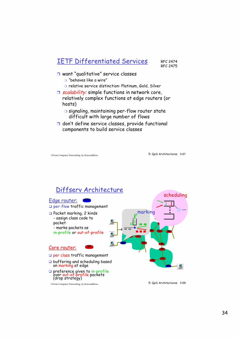
IETF Differentiated Services
❒ want “qualitative” service classes ❍ “behaves like a wire” ❍ relative service distinction: Platinum, Gold, Silver
❒ scalability: simple functions in network core, relatively complex functions at edge routers (or hosts) ❍ signaling, maintaining per-flow router state
difficult with large number of flows ❒ don’t define service classes, provide functional
components to build service classes
RFC 2474 RFC 2475
5: QoS Architectures 5-68 ©From Computer Networking, by Kurose&Ross
Edge router: ! per-flow traffic management ! Packet marking, 2 kinds
- assign class code to packet - marks packets as in-profile or out-of-profile
Core router: ! per class traffic management ! buffering and scheduling based
on marking at edge ! preference given to in-profile
over out-of-profile packets (drop strategy)
Diffserv Architecture scheduling
. . . ρ
σ
marking
35
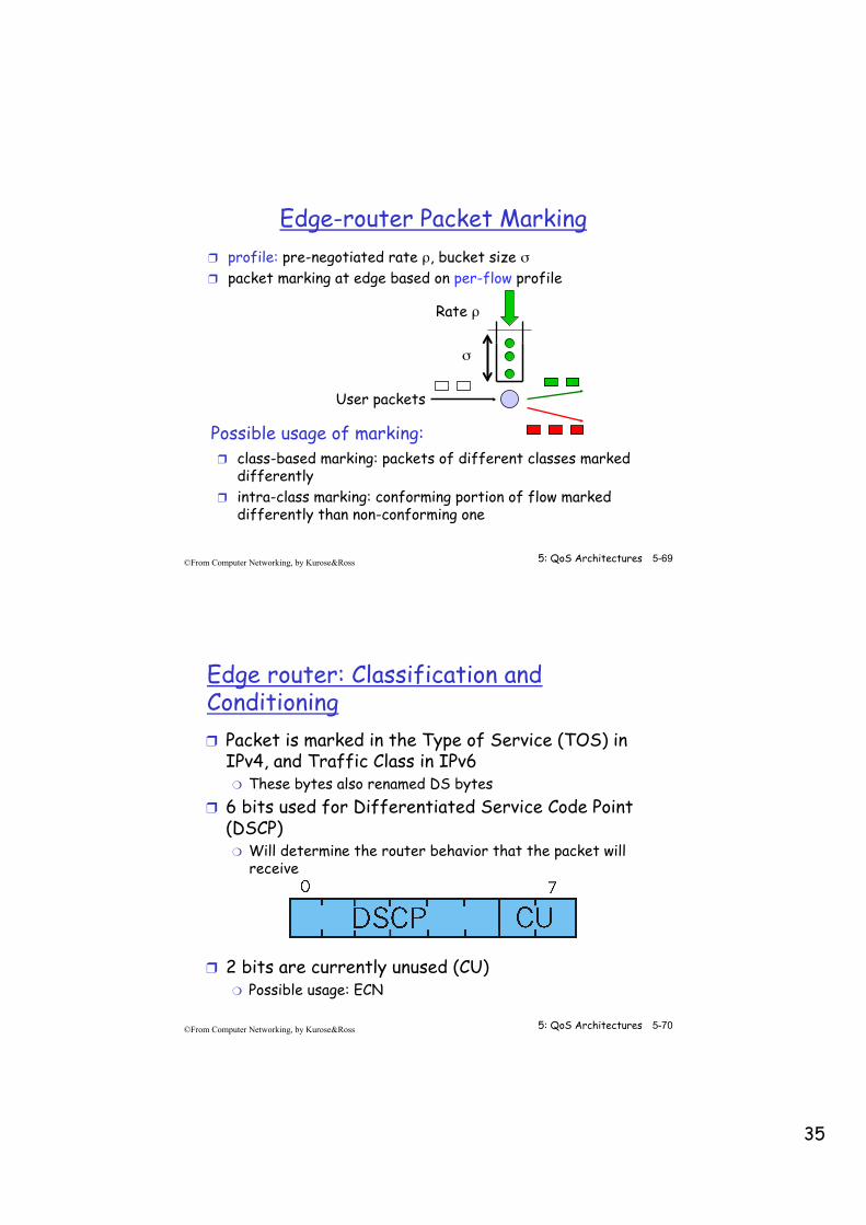
5: QoS Architectures 5-69 ©From Computer Networking, by Kurose&Ross
❒ class-based marking: packets of different classes marked differently
❒ intra-class marking: conforming portion of flow marked differently than non-conforming one
❒ profile: pre-negotiated rate ρ, bucket size σ ❒ packet marking at edge based on per-flow profile
Possible usage of marking:
User packets
Rate ρ
σ
Edge-router Packet Marking
5: QoS Architectures 5-70 ©From Computer Networking, by Kurose&Ross
Edge router: Classification and Conditioning ❒ Packet is marked in the Type of Service (TOS) in
IPv4, and Traffic Class in IPv6 ❍ These bytes also renamed DS bytes
❒ 6 bits used for Differentiated Service Code Point (DSCP) ❍ Will determine the router behavior that the packet will
receive
❒ 2 bits are currently unused (CU) ❍ Possible usage: ECN
36
5: QoS Architectures 5-71 ©From Computer Networking, by Kurose&Ross
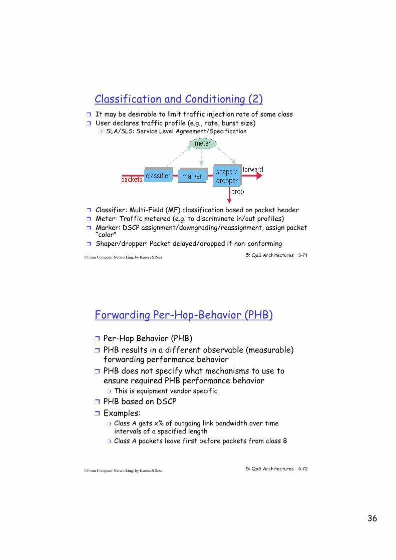
Classification and Conditioning (2) ❒ It may be desirable to limit traffic injection rate of some class ❒ User declares traffic profile (e.g., rate, burst size)
❍ SLA/SLS: Service Level Agreement/Specification
❒ Classifier: Multi-Field (MF) classification based on packet header ❒ Meter: Traffic metered (e.g. to discriminate in/out profiles) ❒ Marker: DSCP assignment/downgrading/reassignment, assign packet
“color” ❒ Shaper/dropper: Packet delayed/dropped if non-conforming
5: QoS Architectures 5-72 ©From Computer Networking, by Kurose&Ross
Forwarding Per-Hop-Behavior (PHB)
❒ Per-Hop Behavior (PHB) ❒ PHB results in a different observable (measurable)
forwarding performance behavior ❒ PHB does not specify what mechanisms to use to
ensure required PHB performance behavior ❍ This is equipment vendor specific
❒ PHB based on DSCP ❒ Examples:
❍ Class A gets x% of outgoing link bandwidth over time intervals of a specified length
❍ Class A packets leave first before packets from class B
37
5: QoS Architectures 5-73 ©From Computer Networking, by Kurose&Ross
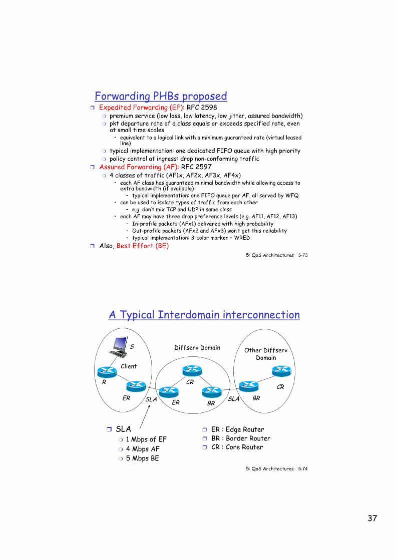
Forwarding PHBs proposed ❒ Expedited Forwarding (EF): RFC 2598
❍ premium service (low loss, low latency, low jitter, assured bandwidth) ❍ pkt departure rate of a class equals or exceeds specified rate, even
at small time scales • equivalent to a logical link with a minimum guaranteed rate (virtual leased
line) ❍ typical implementation: one dedicated FIFO queue with high priority ❍ policy control at ingress: drop non-conforming traffic
❒ Assured Forwarding (AF): RFC 2597 ❍ 4 classes of traffic (AF1x, AF2x, AF3x, AF4x)
• each AF class has guaranteed minimal bandwidth while allowing access to extra bandwidth (if available)
– typical implementation: one FIFO queue per AF, all served by WFQ • can be used to isolate types of traffic from each other
– e.g. don’t mix TCP and UDP in same class • each AF may have three drop preference levels (e.g. AF11, AF12, AF13)
– In-profile packets (AFx1) delivered with high probability – Out-profile packets (AFx2 and AFx3) won’t get this reliability – typical implementation: 3-color marker + WRED
❒ Also, Best Effort (BE)
5: QoS Architectures 5-74 ©From Computer Networking, by Kurose&Ross
A Typical Interdomain interconnection
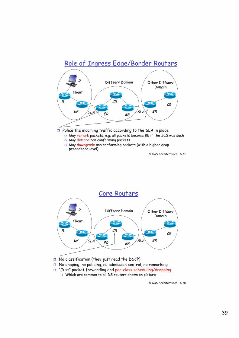
❒ ER : Edge Router ❒ BR : Border Router ❒ CR : Core Router
❒ SLA ❍ 1 Mbps of EF ❍ 4 Mbps AF ❍ 5 Mbps BE
Diffserv Domain Other Diffserv Domain
Client
S
R
ER ER
CR
BR BR
CR
SLA SLA
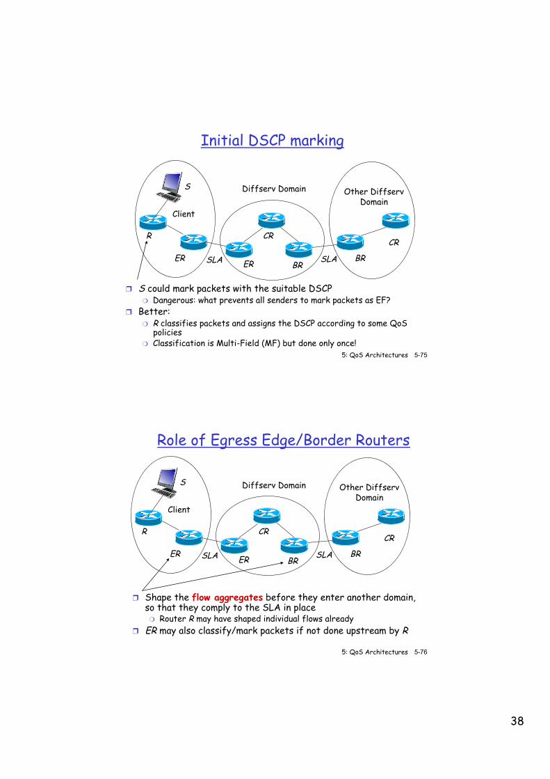
38
5: QoS Architectures 5-75 ©From Computer Networking, by Kurose&Ross
Initial DSCP marking
❒ S could mark packets with the suitable DSCP ❍ Dangerous: what prevents all senders to mark packets as EF?
❒ Better: ❍ R classifies packets and assigns the DSCP according to some QoS
policies ❍ Classification is Multi-Field (MF) but done only once!
Diffserv Domain Other Diffserv Domain
Client
S
R
ER ER
CR
BR BR
CR
SLA SLA
5: QoS Architectures 5-76 ©From Computer Networking, by Kurose&Ross
Role of Egress Edge/Border Routers
❒ Shape the flow aggregates before they enter another domain, so that they comply to the SLA in place ❍ Router R may have shaped individual flows already
❒ ER may also classify/mark packets if not done upstream by R
Diffserv Domain Other Diffserv Domain
Client
S
R
ER ER
CR
BR BR
CR
SLA SLA
39
5: QoS Architectures 5-77 ©From Computer Networking, by Kurose&Ross
Role of Ingress Edge/Border Routers
❒ Police the incoming traffic according to the SLA in place ❍ May remark packets, e.g. all packets become BE if the SLS was such ❍ May discard non conforming packets ❍ May downgrade non conforming packets (with a higher drop
precedence level)
Diffserv Domain Other Diffserv Domain
Client
S
R
ER ER
CR
BR BR
CR
SLA SLA
5: QoS Architectures 5-78 ©From Computer Networking, by Kurose&Ross
Core Routers
❒ No classification (they just read the DSCP) ❒ No shaping, no policing, no admission control, no remarking ❒ “Just” packet forwarding and per-class scheduling/dropping
❍ Which are common to all DS routers shown on picture
Diffserv Domain Other Diffserv Domain
Client
S
R
ER ER
CR
BR BR
CR
SLA SLA
40
5: QoS Architectures 5-79 ©From Computer Networking, by Kurose&Ross
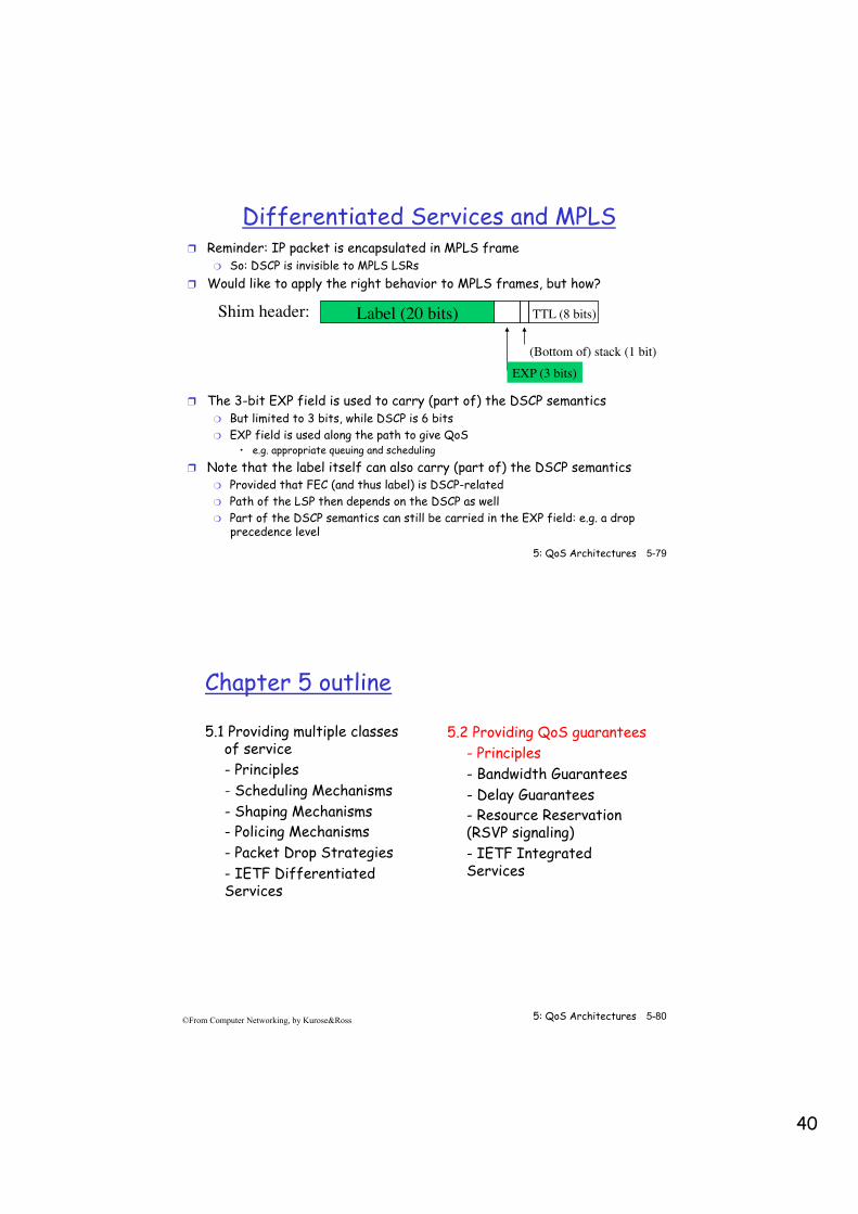
Differentiated Services and MPLS
❒ Reminder: IP packet is encapsulated in MPLS frame ❍ So: DSCP is invisible to MPLS LSRs
❒ Would like to apply the right behavior to MPLS frames, but how?
Label (20 bits)Shim header: TTL (8 bits)
(Bottom of) stack (1 bit)EXP (3 bits)
❒ The 3-bit EXP field is used to carry (part of) the DSCP semantics ❍ But limited to 3 bits, while DSCP is 6 bits ❍ EXP field is used along the path to give QoS
• e.g. appropriate queuing and scheduling
❒ Note that the label itself can also carry (part of) the DSCP semantics ❍ Provided that FEC (and thus label) is DSCP-related ❍ Path of the LSP then depends on the DSCP as well ❍ Part of the DSCP semantics can still be carried in the EXP field: e.g. a drop
precedence level
5: QoS Architectures 5-80 ©From Computer Networking, by Kurose&Ross
Chapter 5 outline
5.1 Providing multiple classes of service - Principles - Scheduling Mechanisms - Shaping Mechanisms - Policing Mechanisms - Packet Drop Strategies - IETF Differentiated Services
5.2 Providing QoS guarantees - Principles - Bandwidth Guarantees - Delay Guarantees - Resource Reservation (RSVP signaling) - IETF Integrated Services
41
5: QoS Architectures 5-81 ©From Computer Networking, by Kurose&Ross
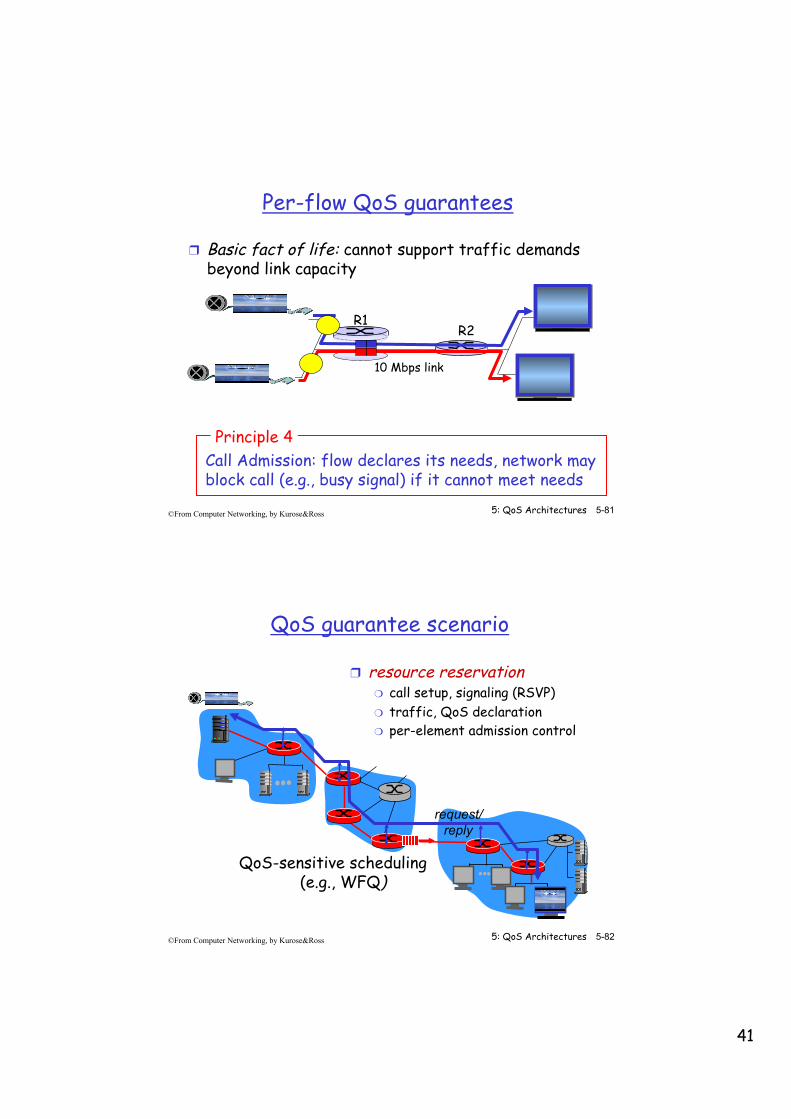
Per-flow QoS guarantees
❒ Basic fact of life: cannot support traffic demands beyond link capacity
Call Admission: flow declares its needs, network may block call (e.g., busy signal) if it cannot meet needs
Principle 4
R1 R2
10 Mbps link
5: QoS Architectures 5-82 ©From Computer Networking, by Kurose&Ross
QoS guarantee scenario
❒ resource reservation ❍ call setup, signaling (RSVP) ❍ traffic, QoS declaration ❍ per-element admission control
QoS-sensitive scheduling (e.g., WFQ)
request/ reply

42
5: QoS Architectures 5-83 ©From Computer Networking, by Kurose&Ross
IETF Integrated Services
❒ architecture for providing QoS guarantees in IP networks for individual application sessions
❒ resource reservation: routers maintain state info (a la VC) of allocated resources, QoS requirements
❒ admit/deny new call setup requests:
Question: can newly arriving flow be admitted with performance guarantees while not violating QoS guarantees made to already admitted flows?
5: QoS Architectures 5-84 ©From Computer Networking, by Kurose&Ross
Chapter 5 outline
5.1 Providing multiple classes of service - Principles - Scheduling Mechanisms - Shaping Mechanisms - Policing Mechanisms - Packet Drop Strategies - IETF Differentiated Services
5.2 Providing QoS guarantees - Principles - Bandwidth Guarantees - Delay Guarantees - Resource Reservation (RSVP signaling) - IETF Integrated Services
43
5: QoS Architectures 5-85 ©From Computer Networking, by Kurose&Ross
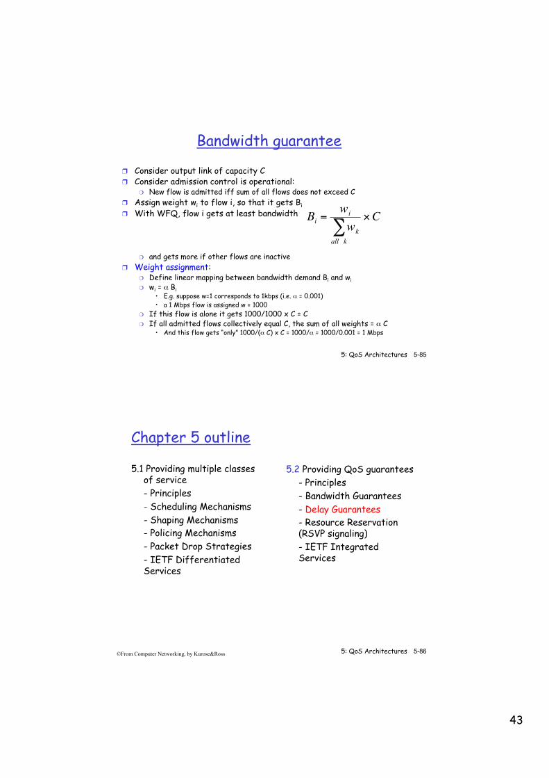
Bandwidth guarantee
❒ Consider output link of capacity C ❒ Consider admission control is operational:
❍ New flow is admitted iff sum of all flows does not exceed C ❒ Assign weight wi to flow i, so that it gets Bi ❒ With WFQ, flow i gets at least bandwidth
❍ and gets more if other flows are inactive ❒ Weight assignment:
❍ Define linear mapping between bandwidth demand Bi and wi ❍ wi = α Bi
• E.g. suppose w=1 corresponds to 1kbps (i.e. α = 0.001) • a 1 Mbps flow is assigned w = 1000
❍ If this flow is alone it gets 1000/1000 x C = C ❍ If all admitted flows collectively equal C, the sum of all weights = α C
• And this flow gets “only” 1000/(α C) x C = 1000/α = 1000/0.001 = 1 Mbps
€
Bi =wi
wkall k∑
×C
5: QoS Architectures 5-86 ©From Computer Networking, by Kurose&Ross
Chapter 5 outline
5.1 Providing multiple classes of service - Principles - Scheduling Mechanisms - Shaping Mechanisms - Policing Mechanisms - Packet Drop Strategies - IETF Differentiated Services
5.2 Providing QoS guarantees - Principles - Bandwidth Guarantees - Delay Guarantees - Resource Reservation (RSVP signaling) - IETF Integrated Services

44
5: QoS Architectures 5-87 ©From Computer Networking, by Kurose&Ross
Policing and QoS guarantees
❒ token bucket, WFQ combine to provide guaranteed upper bound on delay, i.e., QoS guarantee!
WFQ
token rate, ρ
bucket size, σ per-flow rate, g
arriving traffic
arriving traffic
Max queuing delay σ/g ~ ~
5: QoS Architectures 5-88 ©From Computer Networking, by Kurose&Ross
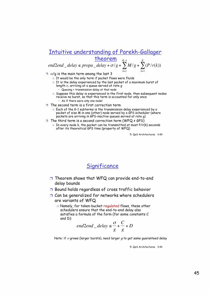
Parekh-Gallager theorem [Parekh 1992, Cruz 1988]
❒ Let a flow be allocated weights at each WFQ scheduler along its path, so that the least bandwidth it is allocated is g
❒ Let it be token-bucket regulated (ρ,σ) with g ≥ ρ ❒ Let the flow pass through K WFQ schedulers, where
the kth scheduler has a rate r(k) = output link rate ❍ Of course, g ≤ r(k)
❒ Let the largest packet allowed in the network be P ❒ Let the largest packet allowed on this flow be M
€
end2end _ delay ≤ propa_ delay +σ /g + M /g + (P /r(k)k=1
K
∑k=1
K−1
∑ )
45
5: QoS Architectures 5-89 ©From Computer Networking, by Kurose&Ross
Intuitive understanding of Parekh-Gallager theorem
❒ σ/g is the main term among the last 3 ❍ It would be the only term if packet flows were fluids ❍ It is the delay experienced by the last packet of a maximum burst of
length σ, arriving at a queue served at rate g • Queuing + transmission delay at that node
❍ Suppose this delay is experienced in the first node, then subsequent nodes receive no burst, so that this term is accounted for only once
• As if there were only one node! ❒ The second term is a first correction term
❍ Each of the K-1 subterms is the transmission delay experienced by a packet of size M in one (other) node served by a GPS scheduler (where packets are arriving in GPS-inactive queues served at rate g)
❒ The third term is a second correction term (WFQ ≠ GPS) ❍ In every node k, the packet can be transmitted at most P/r(k) seconds
after its theoretical GPS time (property of WFQ)
€
end2end _ delay ≤ propa_ delay +σ /g + M /g + (P /r(k)k=1
K
∑k=1
K−1
∑ )
5: QoS Architectures 5-90 ©From Computer Networking, by Kurose&Ross
Significance
❒ Theorem shows that WFQ can provide end-to-end delay bounds
❒ Bound holds regardless of cross traffic behavior ❒ Can be generalized for networks where schedulers
are variants of WFQ ❍ Namely, for token-bucket regulated flows, these other
schedulers ensure that the end-to-end delay also satisfies a formula of the form (for some constants C and D):
€
end2end _ delay ≤ σg
+Cg
+D
Note: if σ grows (larger bursts), need larger g to get same guaranteed delay
46
5: QoS Architectures 5-91 ©From Computer Networking, by Kurose&Ross
Problems
❒ To get a delay bound, need to pick g ❍ the lower the delay bounds, the larger g needs to be (when σ is
fixed) ❍ large g => exclusion of more competitors from link ❍ g can be very large, in some cases several times the peak rate of
the source! ❒ Sources must be leaky-bucket regulated ❒ WFQ couples delay and bandwidth allocations
❍ low delay requires allocating more bandwidth ❍ wastes bandwidth for low-bandwidth low-delay sources
• E.g. voice ❍ not a problem when several flows are aggregated in the same
class (and queue)
5: QoS Architectures 5-92 ©From Computer Networking, by Kurose&Ross
Chapter 5 outline
5.1 Providing multiple classes of service - Principles - Scheduling Mechanisms - Shaping Mechanisms - Policing Mechanisms - Packet Drop Strategies - IETF Differentiated Services
5.2 Providing QoS guarantees - Principles - Bandwidth Guarantees - Delay Guarantees - Resource Reservation (RSVP signaling) - IETF Integrated Services
47
5: QoS Architectures 5-93 ©From Computer Networking, by Kurose&Ross
Signaling in the Internet
connectionless (stateless)
forwarding by IP routers
best effort service
no network signaling protocols
in initial IP design
+ =
❒ New requirement: reserve resources along end-to-end path (end system, routers) for QoS for multimedia applications
5: QoS Architectures 5-94 ©From Computer Networking, by Kurose&Ross
Principles
Arriving session must: ❒ declare its QoS requirement
❍ R-spec: defines the QoS being requested ❒ characterize traffic it will send into network
❍ T-spec: defines traffic characteristics
Need signaling protocol: ❒ to carry R-spec and T-spec to routers (where reservation is
required) ❒ RSVP: Resource reSerVation Protocol [RFC 2205]
❍ “ … allow users to communicate requirements to network in robust and efficient way.” i.e., signaling !
❒ earlier Internet Signaling protocol: ST-II [RFC 1819]
48
5: QoS Architectures 5-95 ©From Computer Networking, by Kurose&Ross
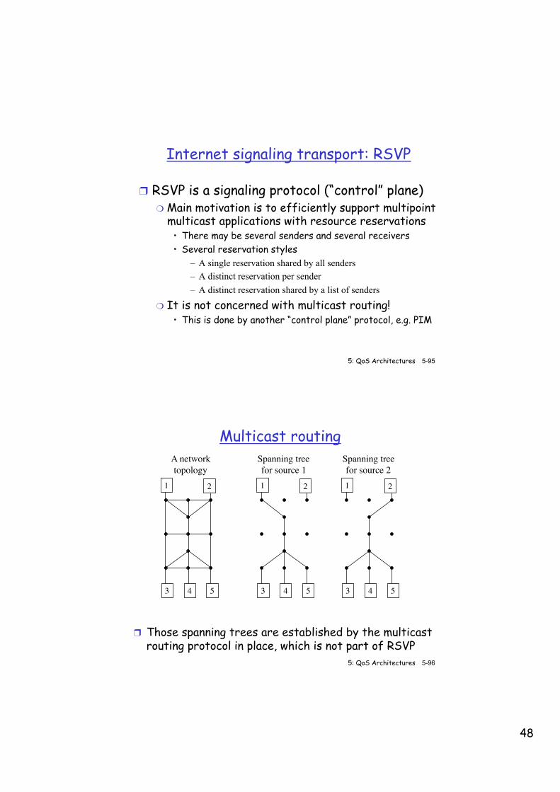
Internet signaling transport: RSVP
❒ RSVP is a signaling protocol (“control” plane) ❍ Main motivation is to efficiently support multipoint
multicast applications with resource reservations • There may be several senders and several receivers • Several reservation styles
– A single reservation shared by all senders – A distinct reservation per sender – A distinct reservation shared by a list of senders
❍ It is not concerned with multicast routing! • This is done by another “control plane” protocol, e.g. PIM
5: QoS Architectures 5-96 ©From Computer Networking, by Kurose&Ross
Multicast routing
❒ Those spanning trees are established by the multicast routing protocol in place, which is not part of RSVP
1 2
3 4 5
1 2
3 4 5
1 2
3 4 5
A networktopology
Spanning tree for source 1
Spanning treefor source 2
49
5: QoS Architectures 5-97 ©From Computer Networking, by Kurose&Ross
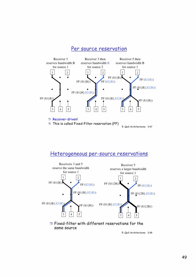
Per source reservation
❒ Receiver-driven! ❒ This is called Fixed-Filter reservation (FF)
1 2
3 4 5
1 2
3 4 5
1 2
3 4 5
Receiver 3reserves bandwidth B
for source 1
Receiver 3 thenreserves bandwidth B
for source 2
Receiver 5 thenreserves bandwidth B
for source 1
FF (S1{B},S2{B}) FF (S1{B})
FF (S1{B},S2{B})
FF (S1{B})
FF (S1{B},S2{B})
FF (S2{B})FF (S1{B}) FF (S2{B})FF (S1{B})
5: QoS Architectures 5-98 ©From Computer Networking, by Kurose&Ross
Heterogeneous per-source reservations
❒ Fixed-filter with different reservations for the same source
1 2
3 4 5
Receivers 3 and 5reserve the same bandwidth
for source 1
1 2
3 4 5
Receiver 5reserves a larger bandwidth
for source 1
FF (S1{B},S2{B}) FF (S1{B})
FF (S1{B},S2{B})
FF (S2{B})FF (S1{B})
FF (S1{B},S2{B}) FF (S1{2B})
FF (S1{2B},S2{B})
FF (S2{B})FF (S1{2B})
50
5: QoS Architectures 5-99 ©From Computer Networking, by Kurose&Ross
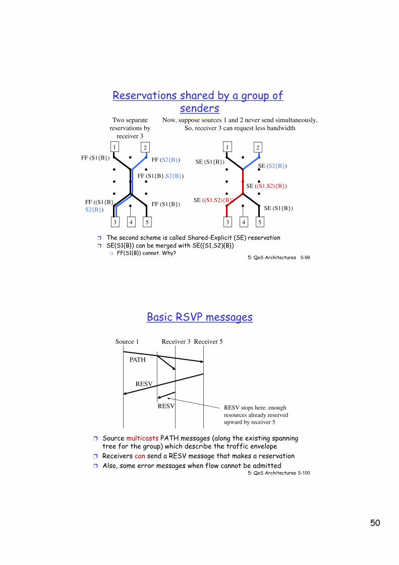
Reservations shared by a group of senders
❒ The second scheme is called Shared-Explicit (SE) reservation ❒ SE(S1{B}) can be merged with SE((S1,S2){B})
❍ FF(S1{B}) cannot. Why?
1 2
3 4 5
Two separatereservations by
receiver 31 2
3 4 5
Now, suppose sources 1 and 2 never send simultaneously,So, receiver 3 can request less bandwidth
FF ((S1{B},S2{B})
FF (S1{B})
FF (S1{B},S2{B})
FF (S2{B})FF (S1{B})
SE ((S1,S2){B})SE (S1{B})
SE (S2{B})SE (S1{B})
SE ((S1,S2){B})
5: QoS Architectures 5-100 ©From Computer Networking, by Kurose&Ross
Basic RSVP messages
❒ Source multicasts PATH messages (along the existing spanning tree for the group) which describe the traffic envelope
❒ Receivers can send a RESV message that makes a reservation ❒ Also, some error messages when flow cannot be admitted
Source 1 Receiver 5Receiver 3
PATH
RESV
RESV RESV stops here: enoughresources already reservedupward by receiver 5
51
5: QoS Architectures 5-101 ©From Computer Networking, by Kurose&Ross
RSVP principles ❒ Receiver-driven reservations ❒ PATH messages:
❍ Source sends PATH messages, which describe the traffic envelope (TSPEC)
❍ They are multicast along a spanning tree to all receivers in the group • The Spanning Tree management is not the business of RSVP!
❍ PATH sets up next hop towards source(s) ❒ RESV messages:
❍ Receiver can send a RESV message that makes reservation (RSPEC) ❍ RESV contains the amount of resources the receiver wants to reserve ❍ RESV follows (in reverse direction) the same route as the PATH,
thanks to the PATH setup ❍ Travel as far back up as necessary
• Hop-by-hop reservation • RESV is only forwarded towards the source if the reservation request is
larger than the reservation already held for its multicast group
5: QoS Architectures 5-102 ©From Computer Networking, by Kurose&Ross
Reservation styles
❒ The reservation style is specified in the RSVP messages:
❒ Fixed-filters (FF): reserve to receive from one sender ❍ Other sources will not use the reservation
❒ Shared-Explicit (SE): reserve to receive from a subset of senders
❒ Wildcard-Filter (WF): reserve for the group (i.e. to receive from all senders) ❍ Is equivalent to a SE with all sources
❒ Only packets that satisfy the filter specification use the associated reserved resources ❍ Other packets use the remaining available bandwidth, if any, in
best effort mode
52
5: QoS Architectures 5-103 ©From Computer Networking, by Kurose&Ross
Soft state
❒ State in switch controllers (routers) is periodically refreshed ❍ PATH and RESV are sent periodically by sources and receivers
❒ On a link failure, (multicast) routing protocols automatically find another route ❍ The soft state approach ensures that past reservations fade
away ❍ But the new paths are temporarily without QoS! ❍ Can be improved by reducing the RSVP refreshing period
• But adds overhead! ❒ However, if routing tables change for other reasons,
reservations only follow after some time! ❍ Worse than in MPLS where existing VCs (LSPs) remain stable
even when routing tables change!
5: QoS Architectures 5-104 ©From Computer Networking, by Kurose&Ross
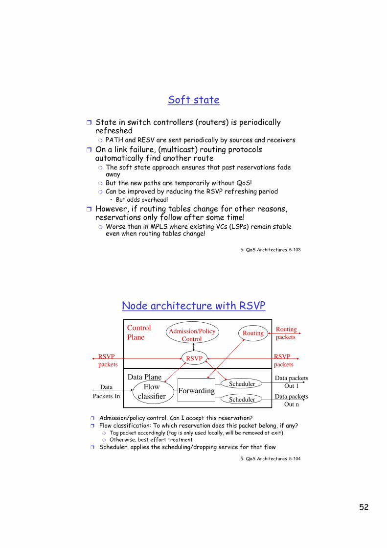
Node architecture with RSVP
❒ Admission/policy control: Can I accept this reservation? ❒ Flow classification: To which reservation does this packet belong, if any?
❍ Tag packet accordingly (tag is only used locally, will be removed at exit) ❍ Otherwise, best effort treatment
❒ Scheduler: applies the scheduling/dropping service for that flow
Flowclassifier
DataPackets In Scheduler
SchedulerForwarding
Data packetsOut 1
Data packetsOut n
RoutingAdmission/PolicyControl
RSVPRSVPpackets
RSVPpackets
ControlPlane
Data Plane
Routingpackets
53
5: QoS Architectures 5-105 ©From Computer Networking, by Kurose&Ross
Flow Description
❒ FilterSpec: identifies the source(s) ❍ With IPv4
• A flow is a layer 4 flow: source identified by an IP address and a port number
❍ With IPv6 • Same as in IPv4, or • Source IP address + flow label (present in the IPv6 header)
❍ With MPLS • A flow is identified by an MPLS label
❒ Session: identifies the destination(s) ❍ IP address (unicast or multicast) + protocol-id + port nr. (option.)
❒ FlowSpec ❍ See next slides (TSPEC and RSPEC)
5: QoS Architectures 5-106 ©From Computer Networking, by Kurose&Ross
Flow specifications (1)
❒ TSPEC ❍ Source traffic envelope in PATH message
• Basically token bucket parameters ❍ TSPEC = (r, b, p, m, M) where
• r = token bucket rate (i.e. related to average source rate) • b = token bucket depth (i.e. related to max burst size) • p = peak transmission rate • m = minimum packet size • M = maximum packet size
❍ (M,p) forms a peak rate token bucket • Packets larger than M are considered best effort
❍ (b,r) forms an average rate token bucket (with burst tolerance b) ❍ Packets smaller than m are considered of size m by token
buckets • To penalize small packets (which create large relative overhead)
54
5: QoS Architectures 5-107 ©From Computer Networking, by Kurose&Ross
Flow Specifications (2) ❒ RSPEC
❍ Receiver’s reservation in RESV message • TSPEC = (r, b, p, m, M) • R = Reserved rate (in bytes/sec)
❍ With WFQ schedulers present in all the K RSVP routers along the path, the end-to-end delay will be bounded as follows:
€
end2end _ delay ≤ propa_ delay + b /R + M /R + (P /P(k)k=1
K
∑k=1
K−1
∑ )
Where P(k) is the output line rate of router k,and P the largest packet allowed in the network
❒ The larger R, the lower the guaranteed delay ❒ Problem: receiver has to know K, P and P(k) for all k to compute
R knowing its maximum end-to-end-delay, M and b
5: QoS Architectures 5-108 ©From Computer Networking, by Kurose&Ross
Flow Specification (3)
❒ Solution: ❒ The PATH message also carries an ADSPEC
❍ ADSPEC = (C, D) is updated by each hop on the path
C = MVisitedHops
∑
€
D = ((P /P(k)VisitedHops∑ ) + link _ propa_ delay(k))
❒ Knowing the values of C and D as accumulated along the path, the receiver can compute the R needed to get a maximum delay ❍ R can be > r, and even > p
❒ If no delay guarantee is needed ❍ R = r is just fine to guarantee the average rate
55
5: QoS Architectures 5-109 ©From Computer Networking, by Kurose&Ross
RSVP: does NOT…
❒ specify how resources are to be reserved ❒ rather: a mechanism for communicating needs ❒ typically resource reservation is achieved by setting the
appropriate weight of the flow in every WFQ-like scheduler on the path
❒ determine routes packets will take ❒ that’s the job of routing protocols (e.g. PIM) ❒ signaling decoupled from routing ❒ exception: RSVP used with ERO (Explicit Route Object) to set
up point-to-point MPLS LSPs ❒ interact with forwarding of packets
❒ separation of control (signaling) and data (forwarding) planes
5: QoS Architectures 5-110 ©From Computer Networking, by Kurose&Ross
Chapter 5 outline
5.1 Providing multiple classes of service - Principles - Scheduling Mechanisms - Shaping Mechanisms - Policing Mechanisms - Packet Drop Strategies - IETF Differentiated Services
5.2 Providing QoS guarantees - Principles - Bandwidth Guarantees - Delay Guarantees - Resource Reservation (RSVP signaling) - IETF Integrated Services

56
5: QoS Architectures 5-111 ©From Computer Networking, by Kurose&Ross
Intserv QoS: Service models [rfc2211, rfc 2212]
Guaranteed service: ❒ For applications that need a
worst case delay bound, no queuing loss, and bandwidth guarantees
❒ Router allocates bandwidth and buffer space ❍ Source descriptor: token-
bucket (ρ, σ) + peak rate + MTU
❍ Parekh’s formula: max delay => bandwidth reservation in routers for worst case traffic arrival
Controlled load service: ❒ "a quality of service closely
approximating the QoS that same flow would receive from an unloaded network element.”
❒ Does not deteriorate when the load increases (more or less same delay, loss rate and bandwidth)
❒ Good for applications that can tolerate a certain amount of delay (variation) and loss
❒ R = r in RSPEC would just achieve it
5: QoS Architectures 5-112 ©From Computer Networking, by Kurose&Ross
Chapter 5: Summary
Providing multiple classes of service:
❒ Scheduling Mechanisms (Fairness, GPS, WFQ)
❒ Shaping/Policing Mechanisms (Token Bucket)
❒ Packet Drop Strategies (WRED)
❒ IETF Differentiated Services
❒ Can scale, but only deployed within some domains, not interdomain
Providing QoS guarantees: ❒ Bandwidth Guarantees ❒ Delay Guarantees (PG formula) ❒ Resource Reservation (RSVP) ❒ IETF Integrated Services ❒ Not applicable at the Internet
scale, but feasible in a private network or edge network