computer labs: the pc's real time clock (rtc) - 2º...
TRANSCRIPT
Computer Labs The PCrsquos Real Time Clock(RTC)2o MIEIC
Pedro F Souto (pfsfeuppt)
November 24 2014
The Real Time Clock (RTC)
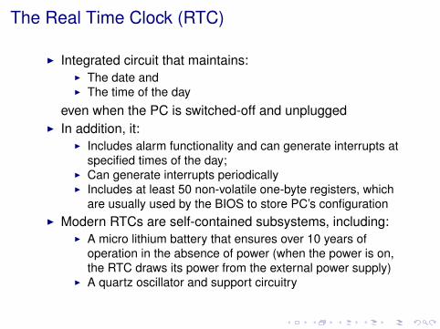
I Integrated circuit that maintainsI The date andI The time of the day
even when the PC is switched-off and unpluggedI In addition it
I Includes alarm functionality and can generate interrupts atspecified times of the day
I Can generate interrupts periodicallyI Includes at least 50 non-volatile one-byte registers which
are usually used by the BIOS to store PCrsquos configurationI Modern RTCs are self-contained subsystems including
I A micro lithium battery that ensures over 10 years ofoperation in the absence of power (when the power is onthe RTC draws its power from the external power supply)
I A quartz oscillator and support circuitry
Lab 6 The RTC (2013)
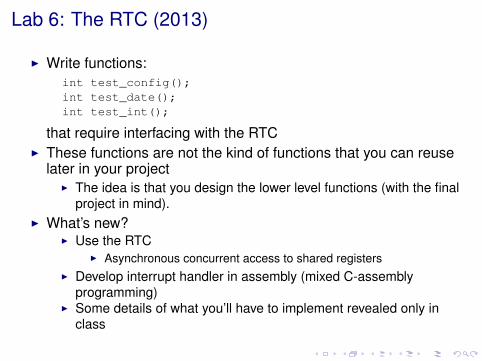
I Write functionsint test_config()int test_date()int test_int()
that require interfacing with the RTCI These functions are not the kind of functions that you can reuse
later in your projectI The idea is that you design the lower level functions (with the final
project in mind)I Whatrsquos new
I Use the RTCI Asynchronous concurrent access to shared registers
I Develop interrupt handler in assembly (mixed C-assemblyprogramming)
I Some details of what yoursquoll have to implement revealed only inclass
The RTCrsquos Internal Address Space
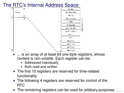
I is an array of at least 64 one-byte registers whosecontent is non-volatile Each register can be
I Addressed individuallyI Both read and written
I The first 10 registers are reserved for time-relatedfunctionality
I The following 4 registers are reserved for control of theRTC
I The remaining registers can be used for arbitrary purposes
Access to the RTC in the PC
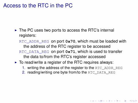
I The PC uses two ports to access the RTCrsquos internalregistersRTC_ADDR_REG on port 0x70 which must be loaded with
the address of the RTC register to be accessedRTC_DATA_REG on port 0x71 which is used to transfer
the data tofrom the RTCrsquos register accessedI To readwrite a register of the RTC requires always
1 writing the address of the register to the RTC_ADDR_REG2 readingwriting one byte fromto the RTC_DATA_REG
Time of the Day Alarm and Date Registers
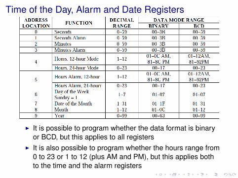
I It is possible to program whether the data format is binaryor BCD but this applies to all registers
I It is also possible to program whether the hours range from0 to 23 or 1 to 12 (plus AM and PM) but this applies bothto the time and the alarm registers
Reading the Date or the Time of the Day (12)
Issue The registers with the date and the time of the day areupdated asynchronously by the RTC every second
I These registers are just an image of non-accessiblecounters that are updated automatically as determinedby the signal generated by the (internal) quartz oscilator
Problem What if there is an update while we are reading thetimedate
I Eg the time updates from 73259 to 73300Question How big can the error be
I Does it matter the order in which registers are read
Reading the Date or the Time of the Day (22)Solution The RTC offers 3 mechanisms to overcome this issue
Update in progress flag (UIP) of the RTCI The RTC sets the UIP of REGISTER_A 244 micros before
starting the update and resets it once the update isdone
Update-ended interrupt of the RTCI If enabled the RTC will interrupt at the end of the
update cycle the next cycle will occur at least 999ms later
I Register_C should be read in the IH to clear theIRQF
Periodic interrupt of the RTCI Periodic interrupts are generated in such a way that
updates occur sensibly in the middle of the period(actually 244micros after)
I As long as the period is long enoughI Thus after a periodic interrupt occurs there are at leastP2 + 244micro seconds before the next update
Contents
Parenthesis Preemptions and Concurrent DDrsquos
Preemptions and Races Reading the Time
What if the DD is preempted while readingthe time eg
Note The arrows labeled IN(XXX)represent one output to port 0x70 andone input from port 0x71
How to prevent this
I Disable interrupts before starting toread (what)
I Enable interrupts again after readingI Define assembly functions to
enabledisable interrupts
DD RTC
IN(Reg_A)
UIP==0IN(hours)
hours++
IN(minutes)
hours
minutes
Other Races caused by PreemptionsWhat if the DD is preempted while trying to access the RTC and
the preempting process accesses the RTCDD1 RTC
outb(0x700x0A)
Reg_C
outb(0x700x0C)
inb(0x71)
inb(0x71)
Reg_
DD2
How to prevent thisI Disabling interrupts may not work with more than one
processorI Interrupts are disabled only on one processorcore
I Need not worry with this for the RTC in MinixI Yoursquoll study concurrency problems in the OS class
Updating the Date or the Time of the Day
Problem Asynchronous updates can also make timedateupdates inconsistent
Solution Set the SET bit of Register_B before updatingI It prevents the RTC from updating the timedate registers
with the values of the datetime keeping countersI At the end of the update the SET bit should be reset so
that the RTC updates the counters with the values of theregisters
Question Can we use the SET bit of REGISTER_B also forreading the datetime registers
Alarm Registers
I The alarm registers allow to configure an alarmI When the time of day registers match the corresponding
alarm registers the RTC alarm generates an alarminterrupt if that interrupt is enabled at the RTC
I Bit AIE (5) of REGISTER_BI The RTC supports donrsquot care values ndash values with the 2
MSB set (11XXXXXX)ndash for alarm registersI These values match any value of the corresponding
register of the time of day register setI This makes it possible to configure alarms for multiple times
of the day without changing the contents of the alarmregisters
I For example if all 3 alarm registers are set to ldquodonrsquot carerdquothen the RTC will generate an alarm every second
InterruptsI The RTC can generate interrupts on 3 different events
Alarm interrupts (AI)Update interrupts (UI)Periodic interrupts (PI) with a period between 122 micros and
05 s as determined by bits RS0-RS3 in REGISTER_AI Each of the interrupts can be enableddisabled individually
using bits AIE UIE and PIE of REGISTER_BI The RTC has only one IRQ line which is connected to line
IRQ0 of PIC2 ie IRQ8I The source of the interrupt can be determined by checking
the flags AF UF and PF of REGISTER_CI Note that more than one of these flags may be set
simultaneouslyI REGISTER_C must be read to clear these flags even if
there is only one enabled interruptI Flags AF UF and PF of REGISTER_C are activated upon
the corresponding events even if interrupts are disabledI It is possible to use polling to check for the corresponding
events
ControlStatus Register A
REGISTER_A
BIT 7 BIT 6 BIT 5 BIT 4 BIT 3 BIT 2 BIT 1 BIT 0UIP DV2 DV1 DV0 RS3 RS2 RS1 RS0
UIP If set to 1 update in progress Do not access timedateregisters
I More precisely this bit is set to 1 244micros before anupdate and reset immediately afterwards
DV2-DV0 Control the couting chain (not relevant)RS3-RS0 Rate selector ndash for periodic interrupts and square
wave output
ControlStatus Register BREGISTER_B
BIT 7 BIT 6 BIT 5 BIT 4 BIT 3 BIT 2 BIT 1 BIT 0SET PIE AIE UIE SQWE DM 2412 DSE
SET Set to 1 to inhibit updates of timedate registersPIE AIE UIE Set to 1 to enable the corresponding
interrupt sourceSQWE Set to 1 to enable square-wave generationDM Set to 1 to set time alarm and date registers in binary
Set to 0 for BCD2412 Set to 1 to set hours range from 0 to 23 and to 0 to
range from 1 to 12DSE Set to 1 to enable Daylight Savings Time and to 0 to
disableI Useless supports only old US DST
IMPORTANT Do not change DM 2412 or DSE because itmay interfere with the OS
I In any case changes to DM or 2412 require settingthe registers affected by those changes
ControlStatus Registers C and D
REGISTER_C
BIT 7 BIT 6 BIT 5 BIT 4 BIT 3 BIT 2 BIT 1 BIT 0IRQF PF AF UF 0 0 0 0
IRQF IRQ line activePF Periodic interrupt pendingAF Alarm interrupt pendingUE Update interrupt pending
REGISTER_D
BIT 7 BIT 6 BIT 5 BIT 4 BIT 3 BIT 2 BIT 1 BIT 0VRT 0 0 0 0 0 0 0
VRT Valid RAMtime ndash set to 0 when the internal lithiumbattery runs out of energy ndash RTC readings arequestionable
Lab 6 (2013) test_config()
What Read and display the configuration of the RTCI The time of day is the state not the configurationI The value of the alarm registers should be considered as
state not as configurationFor class preparation need not display the configuration in a fancy
wayI Just show the value of the registers in hexadecimal
Lab 6 (2013) test_date()
What Display the date and time in a human readable wayI Need not support all formats only those the RTC is configured
withI The mechanism to be used to ensure consistency will be told
in classI Your implementation can use another mechanism but you will
be penalized (between 50 and 67)
For class preparation need not display the configuration in a fancyway
I Just show the value of the registers in hexadecimal
Example Code Waiting for Valid TimeDate
void wait_valid_rtc(void) unsigned long regA = 0
do disable()sys_outb(RTC_ADDR_REG RTC_REG_A)sys_inb(RTC_DATA_REG ampregA)enable()
while ( regA amp RTC_UIP)
I Assuming that functions enable()disable()enabledisable processor interrupts
I May not be what you wantI What if code is preempted or interrupted
Lab 6 (2013) test_int()
What Handle one of the 3 types of interruptsI Which one will be told in class
I Your implementation can handle a different one but you will bepenalized (between 50 and 67)
How Need to implement the handler partially in assemblyI At least the IO part and may be something elseI The variables to be used in the communication between the
assembly code and C code must be declared in assemblyI If you prefer the Intelrsquos syntax check if it is supported
Example Code RTC IH in C
void rtc_ih(void)
int causeunsigned long regA
sys_outb(RTC_ADDR_REG RTC_REG_C)cause = sys_inb(RTC_DATA_REG ampregA)
if( cause amp RTC_UF )handle_update_int()
if( cause amp RTC_AF )handle_alarm_int()
if( cause amp RTC_PF )handle_periodic_int()
Lab6 (2013) Hints for a successful test_int()
Read Register C to clear any pending interruptI For example the interrupt may have occurred the last time
you run lab6 but it was not processed because lab6 wasalready out of the interrupt dispatching loop
Write it in C first and only afterwards in assemblyAssembly file must have S (upper case rsquosrsquo) extension
I Otherwise gcc does not call the C pre-processorHeader files used in assembly should include only defines
I In particular the assembler is not aware of C functionprototypes and will generate an error
sys_iopenable() must be called otherwise if you try toexecute protected instructions yoursquoll get a somewhat weirdmessage such aslab6 255949 0x2ec6 0x22d1 0x28b3 0x100a
Further Reading
I Data sheet of a relatively recent RTC ICI Lab 6 Handout
- Parenthesis Preemptions and Concurrent DDs
-
The Real Time Clock (RTC)
I Integrated circuit that maintainsI The date andI The time of the day
even when the PC is switched-off and unpluggedI In addition it
I Includes alarm functionality and can generate interrupts atspecified times of the day
I Can generate interrupts periodicallyI Includes at least 50 non-volatile one-byte registers which
are usually used by the BIOS to store PCrsquos configurationI Modern RTCs are self-contained subsystems including
I A micro lithium battery that ensures over 10 years ofoperation in the absence of power (when the power is onthe RTC draws its power from the external power supply)
I A quartz oscillator and support circuitry
Lab 6 The RTC (2013)
I Write functionsint test_config()int test_date()int test_int()
that require interfacing with the RTCI These functions are not the kind of functions that you can reuse
later in your projectI The idea is that you design the lower level functions (with the final
project in mind)I Whatrsquos new
I Use the RTCI Asynchronous concurrent access to shared registers
I Develop interrupt handler in assembly (mixed C-assemblyprogramming)
I Some details of what yoursquoll have to implement revealed only inclass
The RTCrsquos Internal Address Space
I is an array of at least 64 one-byte registers whosecontent is non-volatile Each register can be
I Addressed individuallyI Both read and written
I The first 10 registers are reserved for time-relatedfunctionality
I The following 4 registers are reserved for control of theRTC
I The remaining registers can be used for arbitrary purposes
Access to the RTC in the PC
I The PC uses two ports to access the RTCrsquos internalregistersRTC_ADDR_REG on port 0x70 which must be loaded with
the address of the RTC register to be accessedRTC_DATA_REG on port 0x71 which is used to transfer
the data tofrom the RTCrsquos register accessedI To readwrite a register of the RTC requires always
1 writing the address of the register to the RTC_ADDR_REG2 readingwriting one byte fromto the RTC_DATA_REG
Time of the Day Alarm and Date Registers
I It is possible to program whether the data format is binaryor BCD but this applies to all registers
I It is also possible to program whether the hours range from0 to 23 or 1 to 12 (plus AM and PM) but this applies bothto the time and the alarm registers
Reading the Date or the Time of the Day (12)
Issue The registers with the date and the time of the day areupdated asynchronously by the RTC every second
I These registers are just an image of non-accessiblecounters that are updated automatically as determinedby the signal generated by the (internal) quartz oscilator
Problem What if there is an update while we are reading thetimedate
I Eg the time updates from 73259 to 73300Question How big can the error be
I Does it matter the order in which registers are read
Reading the Date or the Time of the Day (22)Solution The RTC offers 3 mechanisms to overcome this issue
Update in progress flag (UIP) of the RTCI The RTC sets the UIP of REGISTER_A 244 micros before
starting the update and resets it once the update isdone
Update-ended interrupt of the RTCI If enabled the RTC will interrupt at the end of the
update cycle the next cycle will occur at least 999ms later
I Register_C should be read in the IH to clear theIRQF
Periodic interrupt of the RTCI Periodic interrupts are generated in such a way that
updates occur sensibly in the middle of the period(actually 244micros after)
I As long as the period is long enoughI Thus after a periodic interrupt occurs there are at leastP2 + 244micro seconds before the next update
Contents
Parenthesis Preemptions and Concurrent DDrsquos
Preemptions and Races Reading the Time
What if the DD is preempted while readingthe time eg
Note The arrows labeled IN(XXX)represent one output to port 0x70 andone input from port 0x71
How to prevent this
I Disable interrupts before starting toread (what)
I Enable interrupts again after readingI Define assembly functions to
enabledisable interrupts
DD RTC
IN(Reg_A)
UIP==0IN(hours)
hours++
IN(minutes)
hours
minutes
Other Races caused by PreemptionsWhat if the DD is preempted while trying to access the RTC and
the preempting process accesses the RTCDD1 RTC
outb(0x700x0A)
Reg_C
outb(0x700x0C)
inb(0x71)
inb(0x71)
Reg_
DD2
How to prevent thisI Disabling interrupts may not work with more than one
processorI Interrupts are disabled only on one processorcore
I Need not worry with this for the RTC in MinixI Yoursquoll study concurrency problems in the OS class
Updating the Date or the Time of the Day
Problem Asynchronous updates can also make timedateupdates inconsistent
Solution Set the SET bit of Register_B before updatingI It prevents the RTC from updating the timedate registers
with the values of the datetime keeping countersI At the end of the update the SET bit should be reset so
that the RTC updates the counters with the values of theregisters
Question Can we use the SET bit of REGISTER_B also forreading the datetime registers
Alarm Registers
I The alarm registers allow to configure an alarmI When the time of day registers match the corresponding
alarm registers the RTC alarm generates an alarminterrupt if that interrupt is enabled at the RTC
I Bit AIE (5) of REGISTER_BI The RTC supports donrsquot care values ndash values with the 2
MSB set (11XXXXXX)ndash for alarm registersI These values match any value of the corresponding
register of the time of day register setI This makes it possible to configure alarms for multiple times
of the day without changing the contents of the alarmregisters
I For example if all 3 alarm registers are set to ldquodonrsquot carerdquothen the RTC will generate an alarm every second
InterruptsI The RTC can generate interrupts on 3 different events
Alarm interrupts (AI)Update interrupts (UI)Periodic interrupts (PI) with a period between 122 micros and
05 s as determined by bits RS0-RS3 in REGISTER_AI Each of the interrupts can be enableddisabled individually
using bits AIE UIE and PIE of REGISTER_BI The RTC has only one IRQ line which is connected to line
IRQ0 of PIC2 ie IRQ8I The source of the interrupt can be determined by checking
the flags AF UF and PF of REGISTER_CI Note that more than one of these flags may be set
simultaneouslyI REGISTER_C must be read to clear these flags even if
there is only one enabled interruptI Flags AF UF and PF of REGISTER_C are activated upon
the corresponding events even if interrupts are disabledI It is possible to use polling to check for the corresponding
events
ControlStatus Register A
REGISTER_A
BIT 7 BIT 6 BIT 5 BIT 4 BIT 3 BIT 2 BIT 1 BIT 0UIP DV2 DV1 DV0 RS3 RS2 RS1 RS0
UIP If set to 1 update in progress Do not access timedateregisters
I More precisely this bit is set to 1 244micros before anupdate and reset immediately afterwards
DV2-DV0 Control the couting chain (not relevant)RS3-RS0 Rate selector ndash for periodic interrupts and square
wave output
ControlStatus Register BREGISTER_B
BIT 7 BIT 6 BIT 5 BIT 4 BIT 3 BIT 2 BIT 1 BIT 0SET PIE AIE UIE SQWE DM 2412 DSE
SET Set to 1 to inhibit updates of timedate registersPIE AIE UIE Set to 1 to enable the corresponding
interrupt sourceSQWE Set to 1 to enable square-wave generationDM Set to 1 to set time alarm and date registers in binary
Set to 0 for BCD2412 Set to 1 to set hours range from 0 to 23 and to 0 to
range from 1 to 12DSE Set to 1 to enable Daylight Savings Time and to 0 to
disableI Useless supports only old US DST
IMPORTANT Do not change DM 2412 or DSE because itmay interfere with the OS
I In any case changes to DM or 2412 require settingthe registers affected by those changes
ControlStatus Registers C and D
REGISTER_C
BIT 7 BIT 6 BIT 5 BIT 4 BIT 3 BIT 2 BIT 1 BIT 0IRQF PF AF UF 0 0 0 0
IRQF IRQ line activePF Periodic interrupt pendingAF Alarm interrupt pendingUE Update interrupt pending
REGISTER_D
BIT 7 BIT 6 BIT 5 BIT 4 BIT 3 BIT 2 BIT 1 BIT 0VRT 0 0 0 0 0 0 0
VRT Valid RAMtime ndash set to 0 when the internal lithiumbattery runs out of energy ndash RTC readings arequestionable
Lab 6 (2013) test_config()
What Read and display the configuration of the RTCI The time of day is the state not the configurationI The value of the alarm registers should be considered as
state not as configurationFor class preparation need not display the configuration in a fancy
wayI Just show the value of the registers in hexadecimal
Lab 6 (2013) test_date()
What Display the date and time in a human readable wayI Need not support all formats only those the RTC is configured
withI The mechanism to be used to ensure consistency will be told
in classI Your implementation can use another mechanism but you will
be penalized (between 50 and 67)
For class preparation need not display the configuration in a fancyway
I Just show the value of the registers in hexadecimal
Example Code Waiting for Valid TimeDate
void wait_valid_rtc(void) unsigned long regA = 0
do disable()sys_outb(RTC_ADDR_REG RTC_REG_A)sys_inb(RTC_DATA_REG ampregA)enable()
while ( regA amp RTC_UIP)
I Assuming that functions enable()disable()enabledisable processor interrupts
I May not be what you wantI What if code is preempted or interrupted
Lab 6 (2013) test_int()
What Handle one of the 3 types of interruptsI Which one will be told in class
I Your implementation can handle a different one but you will bepenalized (between 50 and 67)
How Need to implement the handler partially in assemblyI At least the IO part and may be something elseI The variables to be used in the communication between the
assembly code and C code must be declared in assemblyI If you prefer the Intelrsquos syntax check if it is supported
Example Code RTC IH in C
void rtc_ih(void)
int causeunsigned long regA
sys_outb(RTC_ADDR_REG RTC_REG_C)cause = sys_inb(RTC_DATA_REG ampregA)
if( cause amp RTC_UF )handle_update_int()
if( cause amp RTC_AF )handle_alarm_int()
if( cause amp RTC_PF )handle_periodic_int()
Lab6 (2013) Hints for a successful test_int()
Read Register C to clear any pending interruptI For example the interrupt may have occurred the last time
you run lab6 but it was not processed because lab6 wasalready out of the interrupt dispatching loop
Write it in C first and only afterwards in assemblyAssembly file must have S (upper case rsquosrsquo) extension
I Otherwise gcc does not call the C pre-processorHeader files used in assembly should include only defines
I In particular the assembler is not aware of C functionprototypes and will generate an error
sys_iopenable() must be called otherwise if you try toexecute protected instructions yoursquoll get a somewhat weirdmessage such aslab6 255949 0x2ec6 0x22d1 0x28b3 0x100a
Further Reading
I Data sheet of a relatively recent RTC ICI Lab 6 Handout
- Parenthesis Preemptions and Concurrent DDs
-
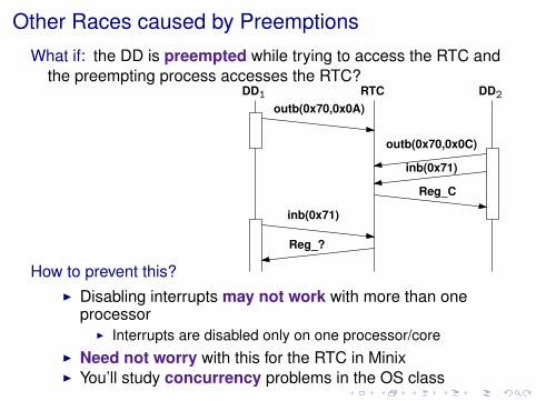
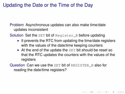
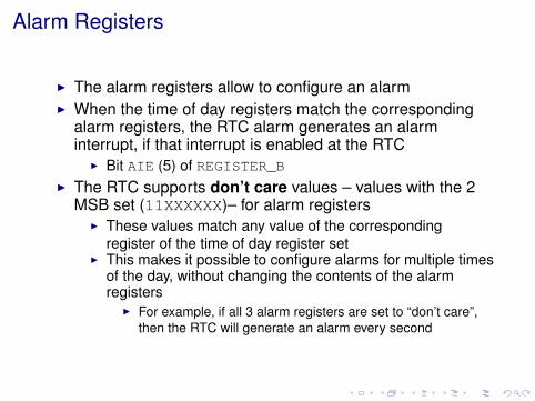
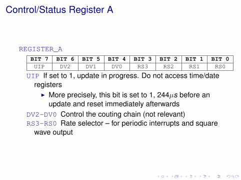
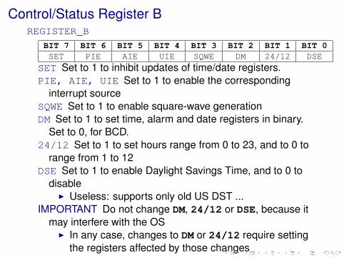
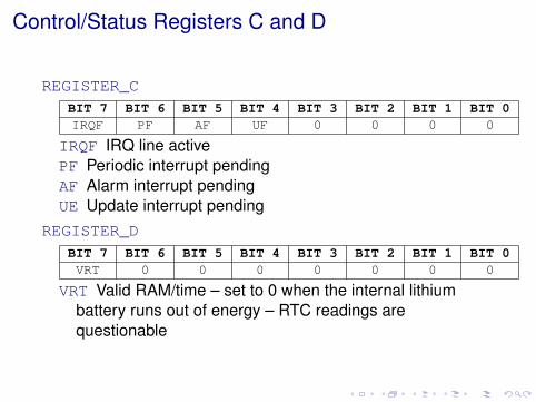
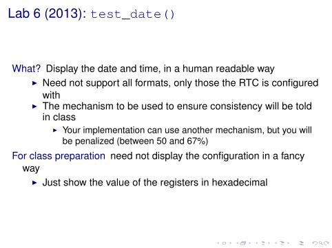
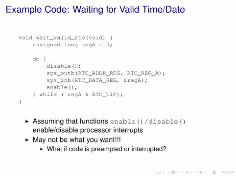
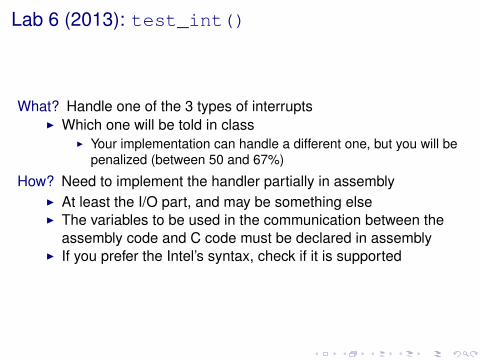
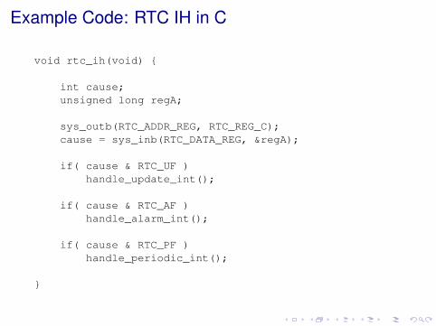
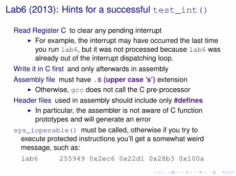

Further Reading
I Data sheet of a relatively recent RTC ICI Lab 6 Handout
- Parenthesis Preemptions and Concurrent DDs
-