computer aided virtual manufacturing using creo parametric978-3-319-23359-8/1.pdf · paul obiora...
TRANSCRIPT

Computer Aided Virtual ManufacturingUsing Creo Parametric

Paul Obiora Kanife
Computer Aided VirtualManufacturing Using CreoParametricEasy to Learn Step by Step Guide
Applicable to both Creo Parametric 2.0 & 3.0
123

Paul Obiora KanifeNotting HillUK
ISBN 978-3-319-23358-1 ISBN 978-3-319-23359-8 (eBook)DOI 10.1007/978-3-319-23359-8
Library of Congress Control Number: 2015949504
Springer Cham Heidelberg New York Dordrecht London© Springer International Publishing Switzerland 2016This work is subject to copyright. All rights are reserved by the Publisher, whether the whole or partof the material is concerned, specifically the rights of translation, reprinting, reuse of illustrations,recitation, broadcasting, reproduction on microfilms or in any other physical way, and transmissionor information storage and retrieval, electronic adaptation, computer software, or by similar or dissimilarmethodology now known or hereafter developed.The use of general descriptive names, registered names, trademarks, service marks, etc. in thispublication does not imply, even in the absence of a specific statement, that such names are exempt fromthe relevant protective laws and regulations and therefore free for general use.The publisher, the authors and the editors are safe to assume that the advice and information in thisbook are believed to be true and accurate at the date of publication. Neither the publisher nor theauthors or the editors give a warranty, express or implied, with respect to the material contained herein orfor any errors or omissions that may have been made.
Printed on acid-free paper
Springer International Publishing AG Switzerland is part of Springer Science+Business Media(www.springer.com)

This book is dedicated to the greatestdesigner and manufacturer man has everknown. The giver of wisdom, knowledgeand free will. The Omniscience,Omnipresence GOD, to whom I give all theglory. Also to my amazing mother,late Mrs. Monica Anayochukwu,Vincent Chidiebere and Dorothy NnennaKanife.
Preface
My drive for writing this tutorial book is based on the fact that during my M.Sc.programme in Advanced Manufacturing Systems Engineering at Brunel UniversityLondon, I found that there were fewer tutorial/textbooks out there in the market thatcovered all areas of computer virtual manufacturing using the Creo Parametricsoftware. Since this book focuses more on Computer Aided Manufacturing(CAM) and less on 3D Modelling using Creo Parametric 2.0 software formerlyknown as Pro Engineer, new users to this software will be introduced briefly to 3Dmodelling using a step-by-step guide to illustrate the process.
This book is aimed at undergraduate and master’s level manufacturing engi-neering students and also mechanical engineering and design students who haveCAD and CAM as an elective option. This book can also be used by technicians,technologists and engineers who want to learn CAM using the Creo Parametricsoftware programme, which is a commercially available product and a registeredtrademark of PTC Inc. in the United States and other countries.
This book is written in such a way so as to make learning CAM using thissoftware program fun and easy to follow and understand. The step-by-step guideillustrated in this tutorial will be better understood if you take time to read the textcarefully, thinking and observing what happens. Therefore, just clicking throughthe command sequence without observing and paying attention to what happens isnot enough. You will also learn more by exploring and experimenting with thedifferent commands on your own.
The first tutorial chapter covers a brief introduction to Creo Parametric. Chapter 2gives a brief introduction to 3D modelling, adding material to Part and the Engravingprocess. Face milling, Profile milling, Surface milling, and Volume Rough millingusing Mill Volume and Window milling processes are covered in the subsequentchapters (Chaps. 3–7). Chapters 8 and 9 covers Expert Machinist and ElectricDischarge Machining, which are 2½ and 2 axis machining processes respectively.Chapters 10–11 cover CNC Lathe Area Turning (2 axis machining process), drillingand boring. Five axis machining, drilling and tapping operations are covered inChaps. 12–13.
vii

In the practical manufacturing application/situation, it is highly advisable toconsult the Machine Tool manual and other relevant books and tooling handbookmanuals, if the user wants to use relevant formulas to calculate the cuttingparameters, and to use the accurate Tool for each different operation. All dimen-sions of the Cutting Tools, Tooling Materials and the Cutting Parameters used inthis tutorial are for illustration purposes only.
Any relevant suggestions/advice on how to improve subsequent editions of thisbook are highly welcome.
The 3D models of Parts used in this tutorial can be emailed to the user onrequest. All requests should be sent to the following email address: [email protected].
viii Preface
Acknowledgments
To my dad Mr. Sylvester Uchechukwu and my late mum Mrs. MonicaAnayochukwu Kanife, I say a huge thank you for laying the foundation on whichI’m standing and for all your love, words of wisdom and encouragement throughoutmy educational pursuits. Not forgetting all my family members for their valuablewords of support and prayers.
A huge thank you to Barrister Cordelia Kanife for all the wonderful words ofencouragement and moral support throughout the ups and downs of writing thisbook.
To all the lecturers and professors who I have learnt from, I say a huge thankyou.
To Anthony Doyle and the editorial team at Springer publishing UK, I say ahuge thank you for having faith in my work and publishing it.
A huge thank you to PTC Inc. for granting me the copyright permission, withoutwhich this book would not have gone to print. And also to Pennie Stone, thepermission and compliance team at Parametric Technology UK (PTC Inc.).
To those who have contributed in one way or the other whom I did not mentionhere, I say a huge thank you.
ix
Contents
1 Introduction . . . . . . . . . . . . . . . . . . . . . . . . . . . . . . . . . . . . . . . . 11.1 What Is Creo Parametric . . . . . . . . . . . . . . . . . . . . . . . . . . 11.2 Starting Creo Parametric . . . . . . . . . . . . . . . . . . . . . . . . . . 21.3 Setup Working Directory . . . . . . . . . . . . . . . . . . . . . . . . . . 61.4 Starting Creo Parametric Manufacturing Application . . . . . . . 7
2 Engraving Tutorial . . . . . . . . . . . . . . . . . . . . . . . . . . . . . . . . . . . 132.1 Step-by-Step Guide on How to Create a 3D Model
Part (REC_PRT1) . . . . . . . . . . . . . . . . . . . . . . . . . . . . . . . 132.1.1 How to Activate the Modelling Application . . . . . . 132.1.2 Activate 2D Sketch Application . . . . . . . . . . . . . . 172.1.3 Activate Extrude Application . . . . . . . . . . . . . . . . 22
2.2 Add Material and Colour Visualisation to the 3D Part . . . . . . 242.2.1 Add the Part Visualisation Colour to Polished
Brass Colour. . . . . . . . . . . . . . . . . . . . . . . . . . . . 242.2.2 Add Material to the Part. . . . . . . . . . . . . . . . . . . . 27
2.3 Create the Engraving Imprint on the Part Surface . . . . . . . . . 362.4 Manufacturing Procedure of the Engraved 3D Part . . . . . . . . 41
2.4.1 Activate the Manufacturing Application . . . . . . . . . 412.4.2 Import and Constrain the Reference Model . . . . . . . 442.4.3 Adding Stock to the Part . . . . . . . . . . . . . . . . . . . 47
2.5 Add Coordinate System (Programme Zero) to the Part . . . . . . 472.6 Set up the Work Centre . . . . . . . . . . . . . . . . . . . . . . . . . . . 502.7 Set up the Operation . . . . . . . . . . . . . . . . . . . . . . . . . . . . . 512.8 Set up the Cutting Tool . . . . . . . . . . . . . . . . . . . . . . . . . . . 532.9 Activate the Engraving Process . . . . . . . . . . . . . . . . . . . . . . 54
2.9.1 Activate Play Path . . . . . . . . . . . . . . . . . . . . . . . . 562.10 Add Material Removal (nccheck_Type) Application . . . . . . . 582.11 Material Removal Simulation Activation . . . . . . . . . . . . . . . 60
xi

2.12 Creating the Cuter Location (CL) Data . . . . . . . . . . . . . . . . 612.13 Create the G-Code Data . . . . . . . . . . . . . . . . . . . . . . . . . . . 63
3 Face Milling Operation . . . . . . . . . . . . . . . . . . . . . . . . . . . . . . . . 693.1 Start the Manufacturing Application . . . . . . . . . . . . . . . . . . 693.2 Importing and Constraining the Saved 3D Part . . . . . . . . . . . 723.3 Adding Stock to the Part . . . . . . . . . . . . . . . . . . . . . . . . . . 753.4 Create Coordinate System (Programme Zero) . . . . . . . . . . . . 773.5 Setup Work Centre . . . . . . . . . . . . . . . . . . . . . . . . . . . . . . 803.6 Setup the Operation. . . . . . . . . . . . . . . . . . . . . . . . . . . . . . 813.7 Setup the Cutting Tool. . . . . . . . . . . . . . . . . . . . . . . . . . . . 833.8 Setup the Face Milling Operation . . . . . . . . . . . . . . . . . . . . 84
3.8.1 Activate Face Milling Play Path . . . . . . . . . . . . . . 873.9 Activate the Material Removal (nccheck_type) . . . . . . . . . . . 893.10 Material Removal Simulation . . . . . . . . . . . . . . . . . . . . . . . 923.11 Create the Cutter Location (CL) Data . . . . . . . . . . . . . . . . . 933.12 Creating the G-Code Data . . . . . . . . . . . . . . . . . . . . . . . . . 95
4 Volume Rough Milling Operation . . . . . . . . . . . . . . . . . . . . . . . . 1074.1 Volume Rough Milling Operation Using Mill Volume. . . . . . 1074.2 Activate the Manufacturing Application . . . . . . . . . . . . . . . . 108
4.2.1 Import the Saved Part . . . . . . . . . . . . . . . . . . . . . 1094.2.2 Constraining the Imported Part . . . . . . . . . . . . . . . 110
4.3 Adding Stock to the Part . . . . . . . . . . . . . . . . . . . . . . . . . . 1124.4 Create Coordinate System (Programme Zero)
for the Workpiece . . . . . . . . . . . . . . . . . . . . . . . . . . . . . . . 1144.5 Set up the Work Centre . . . . . . . . . . . . . . . . . . . . . . . . . . . 1174.6 Set up Operation . . . . . . . . . . . . . . . . . . . . . . . . . . . . . . . . 1174.7 Set up the Cutting Tool . . . . . . . . . . . . . . . . . . . . . . . . . . . 1194.8 Creating the Mill Volume . . . . . . . . . . . . . . . . . . . . . . . . . 120
4.8.1 Create Reference . . . . . . . . . . . . . . . . . . . . . . . . . 1234.8.2 Project Sketch. . . . . . . . . . . . . . . . . . . . . . . . . . . 1254.8.3 First Method of Creating the Extrude Depth . . . . . . 1264.8.4 Second Method of Creating the Extrude Depth . . . . 127
4.9 Volume Rough Milling Operation . . . . . . . . . . . . . . . . . . . . 1284.10 Material Removal Simulation . . . . . . . . . . . . . . . . . . . . . . . 138
5 Profile Milling Operation . . . . . . . . . . . . . . . . . . . . . . . . . . . . . . 1415.1 Activate Profile Milling Operation. . . . . . . . . . . . . . . . . . . . 1425.2 Material Removal Simulation . . . . . . . . . . . . . . . . . . . . . . . 1475.3 Creating the Cuter Location (CL) Data . . . . . . . . . . . . . . . . 1495.4 Create the G-code Data . . . . . . . . . . . . . . . . . . . . . . . . . . . 151
xii Contents
6 Volume Rough Milling Operation, Mill Surfaceand Drill Operation . . . . . . . . . . . . . . . . . . . . . . . . . . . . . . . . . . 1576.1 Volume Rough Milling Operation Using Mill Volume. . . . . . 158
6.1.1 Add Stock to the Imported Part. . . . . . . . . . . . . . . 1586.1.2 Create Coordinate System (Programme Zero) . . . . . 1596.1.3 Setup the Work Centre. . . . . . . . . . . . . . . . . . . . . 1626.1.4 Setup the Operation . . . . . . . . . . . . . . . . . . . . . . . 1636.1.5 Setup the Cutting Tool. . . . . . . . . . . . . . . . . . . . . 1656.1.6 Hide the Holes on Part. . . . . . . . . . . . . . . . . . . . . 1666.1.7 Create Mill Volume. . . . . . . . . . . . . . . . . . . . . . . 1676.1.8 Volume Rough Milling Operation for the First
Mill Volume. . . . . . . . . . . . . . . . . . . . . . . . . . . . 1746.1.9 Create the Second Mill Volume . . . . . . . . . . . . . . 1816.1.10 Volume Rough Milling Operation . . . . . . . . . . . . . 187
6.2 Surface Milling Operation . . . . . . . . . . . . . . . . . . . . . . . . . 1916.3 Drilling of the Holes . . . . . . . . . . . . . . . . . . . . . . . . . . . . . 201
6.3.1 Activate/Un-suppress the Holes . . . . . . . . . . . . . . . 2016.3.2 Create Drilling Operation . . . . . . . . . . . . . . . . . . . 202
6.4 Create the Cutter Location (CL) Data . . . . . . . . . . . . . . . . . 2066.5 Create the G-Code Data . . . . . . . . . . . . . . . . . . . . . . . . . . . 208
7 Volume Rough Milling Using Mill Window and SurfaceMilling Operation . . . . . . . . . . . . . . . . . . . . . . . . . . . . . . . . . . . . 2177.1 Volume Rough Milling Using Mill Window Operation . . . . . 217
7.1.1 Add Stock to the Imported Part Using AssembleWorkpiece Method . . . . . . . . . . . . . . . . . . . . . . . 218
7.1.2 Create Coordinate System for the Workpiece . . . . . 2197.1.3 Setup the Work Centre. . . . . . . . . . . . . . . . . . . . . 2227.1.4 Setup the Operation . . . . . . . . . . . . . . . . . . . . . . . 2237.1.5 Setup the Cutting Tool. . . . . . . . . . . . . . . . . . . . . 2247.1.6 Volume Rough Milling Using Mill Window . . . . . . 2257.1.7 Create Window Mill . . . . . . . . . . . . . . . . . . . . . . 228
7.2 Create Surface Milling . . . . . . . . . . . . . . . . . . . . . . . . . . . . 2317.2.1 Activate the Surface Milling Machining Process . . . 237
8 Expert Machinist . . . . . . . . . . . . . . . . . . . . . . . . . . . . . . . . . . . . 2418.1 Start Expert Machinist . . . . . . . . . . . . . . . . . . . . . . . . . . . . 2418.2 Import Part, Add Stock and Constrain Workpiece . . . . . . . . . 246
8.2.1 Import Part and Add Stock . . . . . . . . . . . . . . . . . . 2468.2.2 Constrain the Part . . . . . . . . . . . . . . . . . . . . . . . . 248
8.3 Create Coordinate System or Programme Zero . . . . . . . . . . . 2508.4 Create the Work Centre . . . . . . . . . . . . . . . . . . . . . . . . . . . 2528.5 Set up Operation . . . . . . . . . . . . . . . . . . . . . . . . . . . . . . . . 2538.6 Create Cutting Tools . . . . . . . . . . . . . . . . . . . . . . . . . . . . . 254
Contents xiii
8.7 Activate the Manufacturing Application . . . . . . . . . . . . . . . . 2628.7.1 Hide the Holes, Pocket, Step and Slots on Part . . . . 262
8.8 Activate the Expert Machinist Application . . . . . . . . . . . . . . 2648.8.1 Create Face Milling Material Removal Sequence. . . 2658.8.2 Create Tool Path for Face1 Milling Operation. . . . . 2678.8.3 Activate the Face Milling Play Path Simualtion. . . . 2738.8.4 View the Material Removal Simulation Process . . . 275
8.9 Activate the Manufacturing Application to CreateMill Volume. . . . . . . . . . . . . . . . . . . . . . . . . . . . . . . . . . . 2768.9.1 Create the Mill Volume . . . . . . . . . . . . . . . . . . . . 2778.9.2 Create References . . . . . . . . . . . . . . . . . . . . . . . . 2798.9.3 Project Line and Curves . . . . . . . . . . . . . . . . . . . . 2808.9.4 Create the Mill Volume Sketch . . . . . . . . . . . . . . . 280
8.10 Create Volume Rough Milling Operation . . . . . . . . . . . . . . . 2838.10.1 Activate the Volume Rough Milling Operation . . . . 286
8.11 Activate the Manufacturing Application . . . . . . . . . . . . . . . . 2888.11.1 Un-suppress the Hidden Holes, Pocket,
Step and Slots. . . . . . . . . . . . . . . . . . . . . . . . . . . 2888.11.2 Make Workpiece Active on the Manufacturing
Window . . . . . . . . . . . . . . . . . . . . . . . . . . . . . . . 2898.12 Activate the Expert Machining Application . . . . . . . . . . . . . 290
8.12.1 Define the Pocket Milling Feature . . . . . . . . . . . . . 2918.12.2 Define the Step Milling Feature . . . . . . . . . . . . . . 2928.12.3 Define the Slots Milling Features . . . . . . . . . . . . . 2948.12.4 Create the Hole Group . . . . . . . . . . . . . . . . . . . . . 296
8.13 Create Tool Paths for Pocket, Step, Slots and Holes . . . . . . . 2998.13.1 Create Tool Path Sequence for Pocket Milling . . . . 2998.13.2 Create Tool Path for Step Milling . . . . . . . . . . . . . 3068.13.3 Create Tool Path for Slot1 Milling . . . . . . . . . . . . 3118.13.4 Create Tool Path for Slot2 Milling . . . . . . . . . . . . 3148.13.5 Create Tool Drill Group 2 . . . . . . . . . . . . . . . . . . 3158.13.6 Run the Whole Operations as Created . . . . . . . . . . 318
8.14 Cutter Location (CL) Data . . . . . . . . . . . . . . . . . . . . . . . . . 3198.15 Create Post Processor . . . . . . . . . . . . . . . . . . . . . . . . . . . . 320
9 Electric Discharge Machining (EDM). . . . . . . . . . . . . . . . . . . . . . 3299.1 Activate Manufacturing Application . . . . . . . . . . . . . . . . . . 3299.2 Import and Constrain the 3D Model . . . . . . . . . . . . . . . . . . 331
9.2.1 Import the Reference Model . . . . . . . . . . . . . . . . . 3319.2.2 Constrain the Imported 3D Part/Model . . . . . . . . . . 332
9.3 Create Automatic Stock for the Part . . . . . . . . . . . . . . . . . . 3339.4 Create Coordinate System (Programme Zero) . . . . . . . . . . . . 3349.5 Create Work Centre. . . . . . . . . . . . . . . . . . . . . . . . . . . . . . 3369.6 Create Operation . . . . . . . . . . . . . . . . . . . . . . . . . . . . . . . . 337
xiv Contents
9.7 Create Cutting Tool. . . . . . . . . . . . . . . . . . . . . . . . . . . . . . 3389.8 Create the Contouring Sequences . . . . . . . . . . . . . . . . . . . . 340
10 CNC Area Lathe Turning . . . . . . . . . . . . . . . . . . . . . . . . . . . . . . 35710.1 Activate the Manufacturing Application . . . . . . . . . . . . . . . . 357
10.1.1 Import Reference Model. . . . . . . . . . . . . . . . . . . . 35910.1.2 Constrain the Model . . . . . . . . . . . . . . . . . . . . . . 360
10.2 Create Automatic Workpiece . . . . . . . . . . . . . . . . . . . . . . . 36110.3 Create Programme Zero (Coordinate System) . . . . . . . . . . . . 36310.4 Create Work Centre. . . . . . . . . . . . . . . . . . . . . . . . . . . . . . 36410.5 Create Operation . . . . . . . . . . . . . . . . . . . . . . . . . . . . . . . . 36510.6 Create Cutting Tool. . . . . . . . . . . . . . . . . . . . . . . . . . . . . . 36610.7 Create Turn Profile Using Method 1 . . . . . . . . . . . . . . . . . . 368
10.7.1 Define References . . . . . . . . . . . . . . . . . . . . . . . . 37110.7.2 Project Lines and Curve . . . . . . . . . . . . . . . . . . . . 372
10.8 Create Area Turning Operation Using the First Method . . . . . 37410.8.1 Activate Play Path . . . . . . . . . . . . . . . . . . . . . . . . 375
10.9 Create Area Turning Operation Using the Second Method . . . 37710.9.1 Create Tool Motion for Area Turning . . . . . . . . . . 37810.9.2 Activate Play Path . . . . . . . . . . . . . . . . . . . . . . . . 38010.9.3 Activate the Material Removal Simulation . . . . . . . 381
10.10 Create the Cuter Location (CL) Data . . . . . . . . . . . . . . . . . . 38210.11 Create the G-code Data . . . . . . . . . . . . . . . . . . . . . . . . . . . 384
11 Area Lathe Turning, Drilling, Boring and Volume Milling . . . . . . 38911.1 Start the Manufacturing Application . . . . . . . . . . . . . . . . . . 389
11.1.1 Import Reference Part . . . . . . . . . . . . . . . . . . . . . 39111.1.2 Constrain the Reference Model . . . . . . . . . . . . . . . 39111.1.3 Create Automatic Workpiece . . . . . . . . . . . . . . . . 39311.1.4 Create Programme Zero (Coordinate System) . . . . . 39411.1.5 Create Work Centre. . . . . . . . . . . . . . . . . . . . . . . 39611.1.6 Create Operation . . . . . . . . . . . . . . . . . . . . . . . . . 39711.1.7 Create Cutting Tools . . . . . . . . . . . . . . . . . . . . . . 399
11.2 Create a Datum Point . . . . . . . . . . . . . . . . . . . . . . . . . . . . 40211.3 Create Turn Profile . . . . . . . . . . . . . . . . . . . . . . . . . . . . . . 40511.4 Create Area Turning Sequence . . . . . . . . . . . . . . . . . . . . . . 411
11.4.1 Create Tool Motions for Area Turning . . . . . . . . . . 41211.4.2 Activate Play Path . . . . . . . . . . . . . . . . . . . . . . . . 414
11.5 Create Drilling Sequence . . . . . . . . . . . . . . . . . . . . . . . . . . 41511.6 Create Turn Profile for the Internal Hole Diameter . . . . . . . . 42111.7 Create Area Turning for the Internal Hole Diameter . . . . . . . 426
11.7.1 Create Tool Motion for Area Turning . . . . . . . . . . 42711.7.2 Activate Play Path . . . . . . . . . . . . . . . . . . . . . . . . 429
Contents xv
11.8 Create New Coordinate System, Work Centre, Datumand Operation for the Volume Mill Process . . . . . . . . . . . . . 43011.8.1 Create a New Coordinate System . . . . . . . . . . . . . 43011.8.2 Create New Work Centre (MILL02) . . . . . . . . . . . 43211.8.3 Create a New Datum Plane. . . . . . . . . . . . . . . . . . 43311.8.4 Create Operation and Retract Plane . . . . . . . . . . . . 43411.8.5 Create New Mill Volume . . . . . . . . . . . . . . . . . . . 435
11.9 Create the Volume Rough Operation . . . . . . . . . . . . . . . . . . 44011.9.1 Activate the Play Path Operation. . . . . . . . . . . . . . 44311.9.2 Material Removal Simulation for Volume
Rough Milling . . . . . . . . . . . . . . . . . . . . . . . . . . 44511.10 Cuter Location (CL) Data for All Operations . . . . . . . . . . . . 44611.11 Creating the G-Code Data . . . . . . . . . . . . . . . . . . . . . . . . . 448
12 Five-Axis Machining of Intricate Part . . . . . . . . . . . . . . . . . . . . . 45512.1 Volume Rough Milling Using Mill Volume . . . . . . . . . . . . . 456
12.1.1 Start Creo Parametric . . . . . . . . . . . . . . . . . . . . . . 45612.1.2 Import and Constrain the Reference Part . . . . . . . . 45712.1.3 Add Stock to the Part . . . . . . . . . . . . . . . . . . . . . 45912.1.4 Suppress Holes . . . . . . . . . . . . . . . . . . . . . . . . . . 461
12.2 Create Coordinate Systems for the Workpiece. . . . . . . . . . . . 46112.2.1 Create Top (First) Coordinate System . . . . . . . . . . 46212.2.2 Create Bottom (Second) Coordinate System . . . . . . 463
12.3 Set up the Work Centre . . . . . . . . . . . . . . . . . . . . . . . . . . . 46512.4 Set up Operation Using the First Coordinate System
Created (ACS2) . . . . . . . . . . . . . . . . . . . . . . . . . . . . . . . . 46612.5 Set up the Cutting Tools . . . . . . . . . . . . . . . . . . . . . . . . . . 46812.6 Create Mill Volumes . . . . . . . . . . . . . . . . . . . . . . . . . . . . . 477
12.6.1 Create First Mill Volume . . . . . . . . . . . . . . . . . . . 47712.6.2 Create Volume Rough Milling Operation
for the First Mill Volume . . . . . . . . . . . . . . . . . . . 48212.6.3 Create Second Mill Volume . . . . . . . . . . . . . . . . . 48912.6.4 Volume Rough Milling Operation for the Second
Mill Volume. . . . . . . . . . . . . . . . . . . . . . . . . . . . 49412.6.5 Create Third Mill Volume . . . . . . . . . . . . . . . . . . 50012.6.6 Volume Rough Milling Operation for the Third
Mill Volume. . . . . . . . . . . . . . . . . . . . . . . . . . . . 50312.6.7 Create Fourth Mill Volume. . . . . . . . . . . . . . . . . . 50612.6.8 Volume Rough Milling Operation for the Fourth
Mill Volume. . . . . . . . . . . . . . . . . . . . . . . . . . . . 51012.6.9 Create the Fifth Mill Volume . . . . . . . . . . . . . . . . 51512.6.10 Volume Rough Milling Operation for the Fifth
Mill Volume. . . . . . . . . . . . . . . . . . . . . . . . . . . . 519
xvi Contents

12.7 Setup Operation Using the Second CoordinateSystem (ACS3). . . . . . . . . . . . . . . . . . . . . . . . . . . . . . . . . 52412.7.1 Create the First Bottom Mill Volume. . . . . . . . . . . 52512.7.2 Volume Rough Milling Operation for the First
Bottom Mill Volume . . . . . . . . . . . . . . . . . . . . . . 52912.7.3 Create the Second Mill Volume on the Bottom
Side of the Workpiece . . . . . . . . . . . . . . . . . . . . . 53212.7.4 Volume Rough Milling Operation for the Second
Bottom Mill Volume . . . . . . . . . . . . . . . . . . . . . . 53612.7.5 Create the Third Mill Volume on the Bottom
Side of the Workpiece . . . . . . . . . . . . . . . . . . . . . 54012.7.6 Volume Rough Milling Operation for the Third
Bottom Mill Volume . . . . . . . . . . . . . . . . . . . . . . 54312.7.7 Create the Fourth Mill Volume on the Bottom
Side of the Workpiece . . . . . . . . . . . . . . . . . . . . . 54612.7.8 Volume Rough Milling Operation for the Fourth
Bottom Mill Volume . . . . . . . . . . . . . . . . . . . . . . 54912.7.9 Create the Fifth Mill Volume on the Bottom
Side of the Workpiece . . . . . . . . . . . . . . . . . . . . . 55212.7.10 Volume Rough Milling Operation for the Fifth
Mill Volume. . . . . . . . . . . . . . . . . . . . . . . . . . . . 55512.7.11 Create the Sixth Mill Volume on the Workpiece . . . 55712.7.12 Volume Rough Milling Operation for the Sixth
Mill Volume. . . . . . . . . . . . . . . . . . . . . . . . . . . . 56012.8 Surface Milling. . . . . . . . . . . . . . . . . . . . . . . . . . . . . . . . . 565
12.8.1 Create Surface Milling for the Outer Surfaceof the Workpiece. . . . . . . . . . . . . . . . . . . . . . . . . 565
12.9 Create Drill Cycle on Workpiece . . . . . . . . . . . . . . . . . . . . 57312.9.1 Activate the Part . . . . . . . . . . . . . . . . . . . . . . . . . 57412.9.2 Activate the Automatic/Created Workpiece . . . . . . . 57612.9.3 Standard Drilling Operation for 100 mm Hole . . . . 57712.9.4 Standard Drilling Operation for 70 mm Hole . . . . . 58012.9.5 Standard Drilling Operation for 20 mm Hole . . . . . 58412.9.6 Create Tapping Operation for 20 mm Hole. . . . . . . 587
12.10 Create the Cutter Location (CL) Data . . . . . . . . . . . . . . . . . 59212.10.1 Create Cutter Location for OP010 . . . . . . . . . . . . . 59212.10.2 Create Cutter Location for OP020 . . . . . . . . . . . . . 594
12.11 Create the G-Code Data . . . . . . . . . . . . . . . . . . . . . . . . . . . 59712.11.1 Generate the G-Code Data for OP010.ncl . . . . . . . . 59712.11.2 Generate the G-Code Data for OP020.ncl . . . . . . . . 599
Contents xvii

13 Surface Milling of Intricate Cast Part . . . . . . . . . . . . . . . . . . . . . 60113.1 Five Axes Surface Milling of Cast Part . . . . . . . . . . . . . . . . 601
13.1.1 Start New Manufacturing Application . . . . . . . . . . 60113.1.2 Import and Constrain the Reference Model . . . . . . . 603
13.2 Create Programme Zero or Coordinate System . . . . . . . . . . . 60513.3 Create Work Centre. . . . . . . . . . . . . . . . . . . . . . . . . . . . . . 60713.4 Create Operation . . . . . . . . . . . . . . . . . . . . . . . . . . . . . . . . 60813.5 Create Cutting Tool. . . . . . . . . . . . . . . . . . . . . . . . . . . . . . 60913.6 Create Surface Milling Sequences . . . . . . . . . . . . . . . . . . . . 613
13.6.1 Create Surface Milling for Internal Surfaceof the Cast Part . . . . . . . . . . . . . . . . . . . . . . . . . . 613
13.6.2 Create Edge Surface Milling for the OuterCircular Surface of the Cast Part . . . . . . . . . . . . . . 621
13.6.3 Activate on Screen Play for the Outer SurfaceMilling Process . . . . . . . . . . . . . . . . . . . . . . . . . . 629
Further Reading . . . . . . . . . . . . . . . . . . . . . . . . . . . . . . . . . . . . . . . . 633
Index . . . . . . . . . . . . . . . . . . . . . . . . . . . . . . . . . . . . . . . . . . . . . . . . 635
xviii Contents

About the Author
Paul Obiora Kanife is a lecturer in the Department of Mechanical Engineering atCoventry University College UK. He currently teaches Mechanical Engineering,Engineering Science, Design and Engineering Graphics using Creo Parametricdesign software. He is a Fellow of the Institute of Manufacturing (F.I.Manf.) andalso a Member of the Institution of Engineering and Technology (MIET) in UK. Heholds an MSc in Advanced Manufacturing Systems Engineering from BrunelUniversity London and has many years of combined practical industrial engineeringand teaching experience.
xix
List of Figures
Figure 1.1 Welcome to Creo Parametric 2.0 window in conciseform . . . . . . . . . . . . . . . . . . . . . . . . . . . . . . . . . . . . . . 3
Figure 1.2 Quick Access toolbar . . . . . . . . . . . . . . . . . . . . . . . . . . 4Figure 1.3 Ribbon toolbar. . . . . . . . . . . . . . . . . . . . . . . . . . . . . . . 4Figure 1.4 Active Folder browser contents on the Navigator . . . . . . . 5Figure 1.5 Web browser in concise form . . . . . . . . . . . . . . . . . . . . 5Figure 1.6 The Navigator display control button . . . . . . . . . . . . . . . 5Figure 1.7 The Mouse functions . . . . . . . . . . . . . . . . . . . . . . . . . . 5Figure 1.8 Activated select working directory window . . . . . . . . . . . 7Figure 1.9 Activated New dialogue box with part and solid radio
buttons active on type and sub-type groupsrespectively . . . . . . . . . . . . . . . . . . . . . . . . . . . . . . . . . 8
Figure 1.10 New dialogue box with manufacturing and NCAssembly radio buttons active on Type and Sub-typegroups . . . . . . . . . . . . . . . . . . . . . . . . . . . . . . . . . . . . 9
Figure 1.11 New file options dialogue box with mmns_mfg_nchighlighted . . . . . . . . . . . . . . . . . . . . . . . . . . . . . . . . . 10
Figure 1.12 Activated manufacturing main graphic user interface(GUI) window . . . . . . . . . . . . . . . . . . . . . . . . . . . . . . . 11
Figure 1.13 Activated manufacturing ribbon in concise form. . . . . . . . 11Figure 2.1 New dialogue box with Part and Solid highlighted . . . . . . 14Figure 2.2 New File Options dialogue box with solid_part_mmks
highlighted . . . . . . . . . . . . . . . . . . . . . . . . . . . . . . . . . 15Figure 2.3 The Model main Graphic User Interface Window. . . . . . . 16Figure 2.4 Activated Model ribbon/tools in concise form . . . . . . . . . 16Figure 2.5 Activated Sketch dialogue box. . . . . . . . . . . . . . . . . . . . 17Figure 2.6 Updated Sketch dialogue box . . . . . . . . . . . . . . . . . . . . 18Figure 2.7 Activated Sketch tools and datum plane display on the
main Graphic User Interface (GUI) window . . . . . . . . . . 18Figure 2.8 Concise Sketch tools in concise form . . . . . . . . . . . . . . . 19
xxi

Figure 2.9 Orientation of Sketch view on the main graphicwindow. . . . . . . . . . . . . . . . . . . . . . . . . . . . . . . . . . . . 19
Figure 2.10 Activated Rectangle drop-down menu list . . . . . . . . . . . . 20Figure 2.11 Activated Chamfer drop-down menu list . . . . . . . . . . . . . 20Figure 2.12 Activated Fillet drop-down menu list . . . . . . . . . . . . . . . 20Figure 2.13 Sketching of the rectangle on the main graphic
window. . . . . . . . . . . . . . . . . . . . . . . . . . . . . . . . . . . . 21Figure 2.14 Finished Sketch with corner chamfers and fillets . . . . . . . 22Figure 2.15 Concise Extrude dashboard . . . . . . . . . . . . . . . . . . . . . . 22Figure 2.16 Extruded sketched Part . . . . . . . . . . . . . . . . . . . . . . . . . 23Figure 2.17 Extruded 3D Part with corner chamfers and fillets . . . . . . 24Figure 2.18 Activated View ribbon in concise form . . . . . . . . . . . . . . 24Figure 2.19 Activated std-metals.dmt group . . . . . . . . . . . . . . . . . . . 25Figure 2.20 Activated Metals folder drop-down list . . . . . . . . . . . . . . 25Figure 2.21 Activated adv-metal-brass.dmt group . . . . . . . . . . . . . . . 26Figure 2.22 Activated Select dialogue box . . . . . . . . . . . . . . . . . . . . 26Figure 2.23 Activated Select dialogue box . . . . . . . . . . . . . . . . . . . . 26Figure 2.24 The “adv-brass-polished” material colour added
to the Part . . . . . . . . . . . . . . . . . . . . . . . . . . . . . . . . . . 27Figure 2.25 Activated Prepare panel content . . . . . . . . . . . . . . . . . . . 27Figure 2.26 The Model properties dialogue window. . . . . . . . . . . . . . 28Figure 2.27 Activating Change on material section . . . . . . . . . . . . . . 28Figure 2.28 Activated Materials dialogue window . . . . . . . . . . . . . . . 29Figure 2.29 BRASS in Materials in Model section . . . . . . . . . . . . . . 29Figure 2.30 The Material Definition dialogue window . . . . . . . . . . . . 30Figure 2.31 Activating new appearance . . . . . . . . . . . . . . . . . . . . . . 31Figure 2.32 The Material Appearance Editor dialogue window . . . . . . 31Figure 2.33 The activated Metals folder panel . . . . . . . . . . . . . . . . . . 32Figure 2.34 The selected “adv-brass-polished” material to be added
to Part . . . . . . . . . . . . . . . . . . . . . . . . . . . . . . . . . . . . 33Figure 2.35 The “adv-brass-polished_new_app” material is now
added to Appearance section box . . . . . . . . . . . . . . . . . . 34Figure 2.36 The “adv-brass-polished_new_app” material is now
added on the Model section box . . . . . . . . . . . . . . . . . . 35Figure 2.37 Model Properties dialogue box showing the added
material on the Material section . . . . . . . . . . . . . . . . . . . 36Figure 2.38 Updated Sketch dialogue. . . . . . . . . . . . . . . . . . . . . . . . 37Figure 2.39 Activated Sketch tools . . . . . . . . . . . . . . . . . . . . . . . . . 37Figure 2.40 Activated Text dialogue box . . . . . . . . . . . . . . . . . . . . . 38Figure 2.41 Activated Font drop-down menu list . . . . . . . . . . . . . . . . 39Figure 2.42 MANUFACTURING imprint on Part surface and Text
dialogue box . . . . . . . . . . . . . . . . . . . . . . . . . . . . . . . . 39Figure 2.43 Activated File drop-down menu list . . . . . . . . . . . . . . . . 40Figure 2.44 The CONFIRMATION dialogue box . . . . . . . . . . . . . . . 40
xxii List of Figures
Figure 2.45 Activated File drop-down menu list . . . . . . . . . . . . . . . . 41Figure 2.46 The activated New dialogue box . . . . . . . . . . . . . . . . . . 41Figure 2.47 Manufacturing and NC Assembly radio buttons
activated . . . . . . . . . . . . . . . . . . . . . . . . . . . . . . . . . . . 42Figure 2.48 The New File Options dialogue box . . . . . . . . . . . . . . . . 43Figure 2.49 Activated Manufacturing main GUI window . . . . . . . . . . 44Figure 2.50 The activated Open dialogue window in concise
form . . . . . . . . . . . . . . . . . . . . . . . . . . . . . . . . . . . . . . 45Figure 2.51 Constraining imported Part method 1 . . . . . . . . . . . . . . . 45Figure 2.52 Constraining imported Part method 2 . . . . . . . . . . . . . . . 46Figure 2.53 Fully constrained Part on the Manufacturing main GUI
window. . . . . . . . . . . . . . . . . . . . . . . . . . . . . . . . . . . . 46Figure 2.54 Activated Coordinate System dialogue box . . . . . . . . . . . 47Figure 2.55 Selected surfaces and the Coordinate Systems dialogue
box . . . . . . . . . . . . . . . . . . . . . . . . . . . . . . . . . . . . . . 48Figure 2.56 Wrong orientation of X, Y and Z-axes of the Coordinate
Systems . . . . . . . . . . . . . . . . . . . . . . . . . . . . . . . . . . . 48Figure 2.57 Correct orientations of the Coordinate Systems X, Y and
Z-axes. . . . . . . . . . . . . . . . . . . . . . . . . . . . . . . . . . . . . 49Figure 2.58 Arrow indicating ACS1 on the Model Tree . . . . . . . . . . . 49Figure 2.59 Activated Milling Work Centre dialogue box. . . . . . . . . . 50Figure 2.60 Activated Operation tools in concise form . . . . . . . . . . . . 51Figure 2.61 Activated Clearance panel and the Retract plane . . . . . . . 52Figure 2.62 Model Tree showing all the steps achieved . . . . . . . . . . . 52Figure 2.63 Tools Setup dialogue box indicating the Grooving
Tool . . . . . . . . . . . . . . . . . . . . . . . . . . . . . . . . . . . . . . 53Figure 2.64 Activated Engraving dashboard . . . . . . . . . . . . . . . . . . . 54Figure 2.65 T0001, ACS1, MANUFACTURE text added into their
section boxes . . . . . . . . . . . . . . . . . . . . . . . . . . . . . . . . 55Figure 2.66 Engraving Parameters values . . . . . . . . . . . . . . . . . . . . . 55Figure 2.67 Activated Manufacturing ribbon . . . . . . . . . . . . . . . . . . . 56Figure 2.68 Activating Engraving 1[OP010] on the Model Tree . . . . . 56Figure 2.69 Activated Engraving Tool and the PLAY PATH
dialogue box . . . . . . . . . . . . . . . . . . . . . . . . . . . . . . . . 57Figure 2.70 End of on screen Engraving process . . . . . . . . . . . . . . . . 57Figure 2.71 Activated File group . . . . . . . . . . . . . . . . . . . . . . . . . . . 58Figure 2.72 Activated Creo Parametric Options dialogue
window. . . . . . . . . . . . . . . . . . . . . . . . . . . . . . . . . . . . 58Figure 2.73 Activated Configuration Editors application tools . . . . . . . 59Figure 2.74 Find Option dialogue window . . . . . . . . . . . . . . . . . . . . 60Figure 2.75 Activated NC CHECK and NC DISP groups on the
Menu Manager dialogue box . . . . . . . . . . . . . . . . . . . . . 61Figure 2.76 Activated SELECT FEAT and SEL MENU groups on
Menu Manager dialogue box . . . . . . . . . . . . . . . . . . . . . 62
List of Figures xxiii
Figure 2.77 Activated PATH and OUTPUT TYPE groups on MenuManager dialogue box . . . . . . . . . . . . . . . . . . . . . . . . . 62
Figure 2.78 Activated Save a Copy dialogue window in conciseform . . . . . . . . . . . . . . . . . . . . . . . . . . . . . . . . . . . . . . 63
Figure 2.79 Activated PATH group on the Menu Manager dialoguebox . . . . . . . . . . . . . . . . . . . . . . . . . . . . . . . . . . . . . . 63
Figure 2.80 Activated Open dialogue window in concise form . . . . . . 64Figure 2.81 Activated PP OPTIONS Menu Manager dialogue
box . . . . . . . . . . . . . . . . . . . . . . . . . . . . . . . . . . . . . . 64Figure 2.82 Activated PP LIST Menu Manager dialogue box . . . . . . . 65Figure 2.83 Activated INFORMATION WINDOW in concise
form . . . . . . . . . . . . . . . . . . . . . . . . . . . . . . . . . . . . . . 65Figure 3.1 Activated New dialogue box . . . . . . . . . . . . . . . . . . . . . 70Figure 3.2 New dialogue box with Manufacturing and NC
Assembly radio buttons activated . . . . . . . . . . . . . . . . . . 70Figure 3.3 Activated New File Options dialogue box with
mmns_mfg_nc highlighted and clicked . . . . . . . . . . . . . . 71Figure 3.4 Activated Manufacturing main Graphic User Interface
window. . . . . . . . . . . . . . . . . . . . . . . . . . . . . . . . . . . . 72Figure 3.5 Activated File Open dialogue window in a concise
form . . . . . . . . . . . . . . . . . . . . . . . . . . . . . . . . . . . . . . 73Figure 3.6 Constraining imported part using method 1 . . . . . . . . . . . 73Figure 3.7 Constraining the part using method 2 . . . . . . . . . . . . . . . 74Figure 3.8 Part fully constrained . . . . . . . . . . . . . . . . . . . . . . . . . . 74Figure 3.9 Part after exiting Component Placement application . . . . . 75Figure 3.10 Activated Auto-Workpiece creation application
ribbon. . . . . . . . . . . . . . . . . . . . . . . . . . . . . . . . . . . . . 75Figure 3.11 Activated Options panel . . . . . . . . . . . . . . . . . . . . . . . . 76Figure 3.12 Workpiece dimensions . . . . . . . . . . . . . . . . . . . . . . . . . 76Figure 3.13 Created stock on part in the main Manufacturing
graphic window . . . . . . . . . . . . . . . . . . . . . . . . . . . . . . 77Figure 3.14 Activated Coordinate System dialogue box . . . . . . . . . . . 77Figure 3.15 Selection of the part surface used in creating the
Coordinate System axes . . . . . . . . . . . . . . . . . . . . . . . . 78Figure 3.16 Wrong orientations of the X, Y, and Z-axis of the
Coordinate System . . . . . . . . . . . . . . . . . . . . . . . . . . . . 78Figure 3.17 Correct orientations of the X, Y, and Z-axis of the
Coordinate System . . . . . . . . . . . . . . . . . . . . . . . . . . . . 79Figure 3.18 Activated Milling Work Centre dialogue window . . . . . . . 80Figure 3.19 Activated Operation dashboard. . . . . . . . . . . . . . . . . . . . 81Figure 3.20 The Type drop-down menu list on the retract group . . . . . 81Figure 3.21 Activated Clearance panel indicating the Type and
References updates . . . . . . . . . . . . . . . . . . . . . . . . . . . . 82
xxiv List of Figures
Figure 3.22 Workpiece after adding the work centre and operationparameters. . . . . . . . . . . . . . . . . . . . . . . . . . . . . . . . . . 82
Figure 3.23 Model Tree after creating Auto-Workpiece, ACS2,work centre, and operation . . . . . . . . . . . . . . . . . . . . . . 83
Figure 3.24 Activated Tools Setup dialogue window with all addedparameters on Tool. . . . . . . . . . . . . . . . . . . . . . . . . . . . 84
Figure 3.25 Activated Face Milling dashboard in concise form . . . . . . 85Figure 3.26 Activated Reference panel . . . . . . . . . . . . . . . . . . . . . . . 85Figure 3.27 Active Filter selection drop-down list panel . . . . . . . . . . . 85Figure 3.28 Parameter values for face milling process . . . . . . . . . . . . 86Figure 3.29 Manufacturing ribbon toolbar with Play Path tab
activated . . . . . . . . . . . . . . . . . . . . . . . . . . . . . . . . . . . 87Figure 3.30 Activated End Mill Tool and PLAY PATH dialogue
box . . . . . . . . . . . . . . . . . . . . . . . . . . . . . . . . . . . . . . 88Figure 3.31 End of on screen Face milling operation Face Milling
operation. . . . . . . . . . . . . . . . . . . . . . . . . . . . . . . . . . . 88Figure 3.32 Activated File drop-down menu list . . . . . . . . . . . . . . . . 89Figure 3.33 Activated Creo Parametric Options dialogue
window. . . . . . . . . . . . . . . . . . . . . . . . . . . . . . . . . . . . 90Figure 3.34 Activated Configuration Editor application tools. . . . . . . . 91Figure 3.35 Find Option dialogue box . . . . . . . . . . . . . . . . . . . . . . . 92Figure 3.36 Activated NC CHECK Menu Manager dialogue box . . . . 93Figure 3.37 Activated SELECT FEAT Menu Manager dialogue
box . . . . . . . . . . . . . . . . . . . . . . . . . . . . . . . . . . . . . . 94Figure 3.38 PATH Menu Manager dialogue box . . . . . . . . . . . . . . . . 94Figure 3.39 Activated Save a Copy dialogue window in concise
form . . . . . . . . . . . . . . . . . . . . . . . . . . . . . . . . . . . . . . 95Figure 3.40 Activated Open dialogue window in a concise form . . . . . 95Figure 3.41 Activated PP Options Menu Manager dialogue box with
Verbose and Trace Checked Marked. . . . . . . . . . . . . . . . 96Figure 3.42 Activated PP LIST Menu Manager dialogue box . . . . . . . 96Figure 3.43 Activated INFORMATION WINDOW in concise
form . . . . . . . . . . . . . . . . . . . . . . . . . . . . . . . . . . . . . . 97Figure 4.1 Manufacturing and NC Assembly radio buttons
activated . . . . . . . . . . . . . . . . . . . . . . . . . . . . . . . . . . . 108Figure 4.2 New File Options dialogue box with mmns_mfg_nc
highlighted . . . . . . . . . . . . . . . . . . . . . . . . . . . . . . . . . 109Figure 4.3 Activated Open dialogue window in concise form . . . . . . 110Figure 4.4 Activated Component Placement dashboard in concise
form . . . . . . . . . . . . . . . . . . . . . . . . . . . . . . . . . . . . . . 110Figure 4.5 Constraining the imported Part using Method 1 . . . . . . . . 110Figure 4.6 Method 2 of constraining the imported Part . . . . . . . . . . . 111Figure 4.7 Part is fully constrained on the main graphic window . . . . 111
List of Figures xxv
Figure 4.8 Part appearance after exiting the Component Placementapplication. . . . . . . . . . . . . . . . . . . . . . . . . . . . . . . . . . 112
Figure 4.9 Activated Auto-Workpiece Creation tools in conciseform . . . . . . . . . . . . . . . . . . . . . . . . . . . . . . . . . . . . . . 113
Figure 4.10 Activated Options panel showing Workpiecedimensions . . . . . . . . . . . . . . . . . . . . . . . . . . . . . . . . . 113
Figure 4.11 Stock added to imported 3D Part . . . . . . . . . . . . . . . . . . 113Figure 4.12 Activated Coordinate System dialogue box . . . . . . . . . . . 114Figure 4.13 Selecting the Part surface used in creating the
Coordinate System . . . . . . . . . . . . . . . . . . . . . . . . . . . . 114Figure 4.14 Wrong orientations of the X, Y, and Z axis of the
Coordinate System . . . . . . . . . . . . . . . . . . . . . . . . . . . . 115Figure 4.15 Correct orientations of the X, Y, and Z axis of the
Coordinate System . . . . . . . . . . . . . . . . . . . . . . . . . . . . 115Figure 4.16 Part on the main window after adding Stock and
Coordinate System . . . . . . . . . . . . . . . . . . . . . . . . . . . . 116Figure 4.17 Model Tree indicating the renamed ACS1 to ACS3 . . . . . 116Figure 4.18 Acitivated Milling Work Centre dialogue window . . . . . . 117Figure 4.19 Activated Operation dasboard . . . . . . . . . . . . . . . . . . . . 118Figure 4.20 Activated Clearance panel and the Retract plane on
Worpiece surface . . . . . . . . . . . . . . . . . . . . . . . . . . . . . 118Figure 4.21 Model Tree showing ACS3, MILL01, and OP010
[MILL01] . . . . . . . . . . . . . . . . . . . . . . . . . . . . . . . . . . 119Figure 4.22 Tools Setup dialogue window after setting up process. . . . 120Figure 4.23 Activated Mill Volume dashboard in concise form . . . . . . 121Figure 4.24 Extrude application dashboard tools in concise form. . . . . 121Figure 4.25 Activated Placement panel. . . . . . . . . . . . . . . . . . . . . . . 121Figure 4.26 Sketch dialogue box after adding the sketching plane . . . . 122Figure 4.27 Activated Sketch tools in concise form . . . . . . . . . . . . . . 122Figure 4.28 Workpiece orientated correctly on the sketch plane. . . . . . 123Figure 4.29 Activated References dialogue box . . . . . . . . . . . . . . . . . 124Figure 4.30 New references as indicated by the arrows and in the
References section . . . . . . . . . . . . . . . . . . . . . . . . . . . . 124Figure 4.31 Activated Type dialogue box . . . . . . . . . . . . . . . . . . . . . 125Figure 4.32 Projecting the internal rectangle on the sketch plane . . . . . 125Figure 4.33 Activated Extrude tools in concise form . . . . . . . . . . . . . 126Figure 4.34 Activated Options panel after adding the inputs . . . . . . . . 126Figure 4.35 Workpiece showing projected and extrude rectangle . . . . . 127Figure 4.36 Options panel after adding the inputs and the rectangle
to be extruded . . . . . . . . . . . . . . . . . . . . . . . . . . . . . . . 127Figure 4.37 Created Mill volume on the Workpiece. . . . . . . . . . . . . . 128Figure 4.38 Activated NC SEQUENCE and SEQ SETUP group . . . . . 129Figure 4.39 Tools, Parameters, and Volume Check Marked . . . . . . . . 129Figure 4.40 Activated Tools Setup dialogue box . . . . . . . . . . . . . . . . 130
xxvi List of Figures
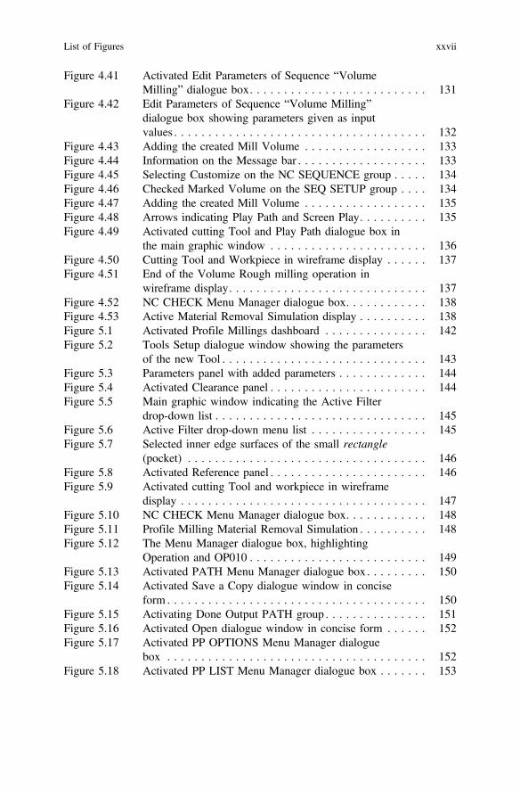
Figure 4.41 Activated Edit Parameters of Sequence “VolumeMilling” dialogue box. . . . . . . . . . . . . . . . . . . . . . . . . . 131
Figure 4.42 Edit Parameters of Sequence “Volume Milling”dialogue box showing parameters given as inputvalues . . . . . . . . . . . . . . . . . . . . . . . . . . . . . . . . . . . . . 132
Figure 4.43 Adding the created Mill Volume . . . . . . . . . . . . . . . . . . 133Figure 4.44 Information on the Message bar . . . . . . . . . . . . . . . . . . . 133Figure 4.45 Selecting Customize on the NC SEQUENCE group . . . . . 134Figure 4.46 Checked Marked Volume on the SEQ SETUP group . . . . 134Figure 4.47 Adding the created Mill Volume . . . . . . . . . . . . . . . . . . 135Figure 4.48 Arrows indicating Play Path and Screen Play. . . . . . . . . . 135Figure 4.49 Activated cutting Tool and Play Path dialogue box in
the main graphic window . . . . . . . . . . . . . . . . . . . . . . . 136Figure 4.50 Cutting Tool and Workpiece in wireframe display . . . . . . 137Figure 4.51 End of the Volume Rough milling operation in
wireframe display. . . . . . . . . . . . . . . . . . . . . . . . . . . . . 137Figure 4.52 NC CHECK Menu Manager dialogue box. . . . . . . . . . . . 138Figure 4.53 Active Material Removal Simulation display . . . . . . . . . . 138Figure 5.1 Activated Profile Millings dashboard . . . . . . . . . . . . . . . 142Figure 5.2 Tools Setup dialogue window showing the parameters
of the new Tool . . . . . . . . . . . . . . . . . . . . . . . . . . . . . . 143Figure 5.3 Parameters panel with added parameters . . . . . . . . . . . . . 144Figure 5.4 Activated Clearance panel . . . . . . . . . . . . . . . . . . . . . . . 144Figure 5.5 Main graphic window indicating the Active Filter
drop-down list . . . . . . . . . . . . . . . . . . . . . . . . . . . . . . . 145Figure 5.6 Active Filter drop-down menu list . . . . . . . . . . . . . . . . . 145Figure 5.7 Selected inner edge surfaces of the small rectangle
(pocket) . . . . . . . . . . . . . . . . . . . . . . . . . . . . . . . . . . . 146Figure 5.8 Activated Reference panel . . . . . . . . . . . . . . . . . . . . . . . 146Figure 5.9 Activated cutting Tool and workpiece in wireframe
display . . . . . . . . . . . . . . . . . . . . . . . . . . . . . . . . . . . . 147Figure 5.10 NC CHECK Menu Manager dialogue box. . . . . . . . . . . . 148Figure 5.11 Profile Milling Material Removal Simulation . . . . . . . . . . 148Figure 5.12 The Menu Manager dialogue box, highlighting
Operation and OP010 . . . . . . . . . . . . . . . . . . . . . . . . . . 149Figure 5.13 Activated PATH Menu Manager dialogue box. . . . . . . . . 150Figure 5.14 Activated Save a Copy dialogue window in concise
form . . . . . . . . . . . . . . . . . . . . . . . . . . . . . . . . . . . . . . 150Figure 5.15 Activating Done Output PATH group . . . . . . . . . . . . . . . 151Figure 5.16 Activated Open dialogue window in concise form . . . . . . 152Figure 5.17 Activated PP OPTIONS Menu Manager dialogue
box . . . . . . . . . . . . . . . . . . . . . . . . . . . . . . . . . . . . . . 152Figure 5.18 Activated PP LIST Menu Manager dialogue box . . . . . . . 153
List of Figures xxvii
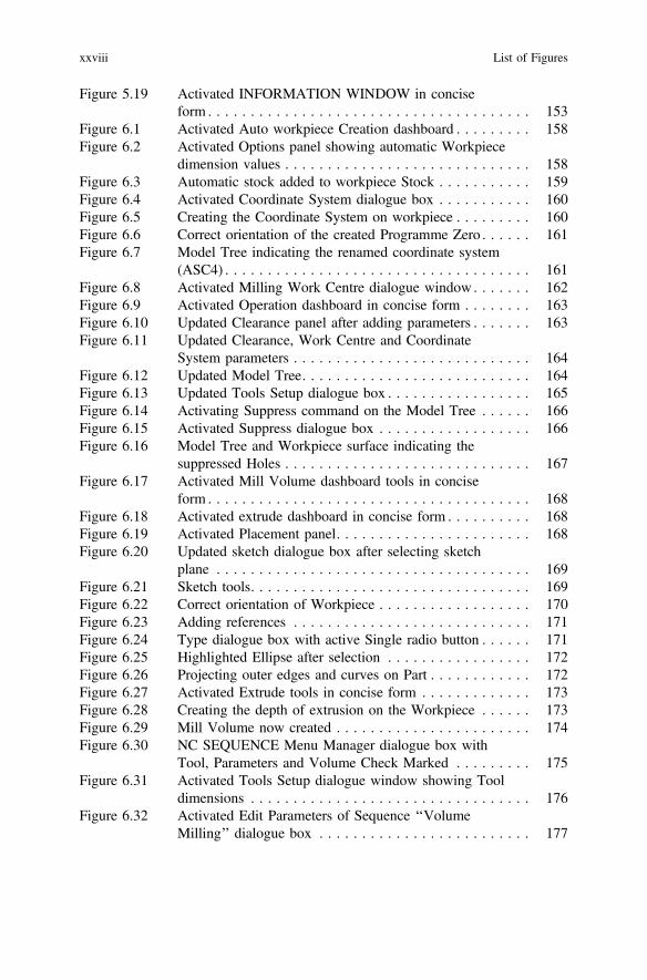
Figure 5.19 Activated INFORMATION WINDOW in conciseform . . . . . . . . . . . . . . . . . . . . . . . . . . . . . . . . . . . . . . 153
Figure 6.1 Activated Auto workpiece Creation dashboard . . . . . . . . . 158Figure 6.2 Activated Options panel showing automatic Workpiece
dimension values . . . . . . . . . . . . . . . . . . . . . . . . . . . . . 158Figure 6.3 Automatic stock added to workpiece Stock . . . . . . . . . . . 159Figure 6.4 Activated Coordinate System dialogue box . . . . . . . . . . . 160Figure 6.5 Creating the Coordinate System on workpiece . . . . . . . . . 160Figure 6.6 Correct orientation of the created Programme Zero . . . . . . 161Figure 6.7 Model Tree indicating the renamed coordinate system
(ASC4) . . . . . . . . . . . . . . . . . . . . . . . . . . . . . . . . . . . . 161Figure 6.8 Activated Milling Work Centre dialogue window . . . . . . . 162Figure 6.9 Activated Operation dashboard in concise form . . . . . . . . 163Figure 6.10 Updated Clearance panel after adding parameters . . . . . . . 163Figure 6.11 Updated Clearance, Work Centre and Coordinate
System parameters . . . . . . . . . . . . . . . . . . . . . . . . . . . . 164Figure 6.12 Updated Model Tree. . . . . . . . . . . . . . . . . . . . . . . . . . . 164Figure 6.13 Updated Tools Setup dialogue box . . . . . . . . . . . . . . . . . 165Figure 6.14 Activating Suppress command on the Model Tree . . . . . . 166Figure 6.15 Activated Suppress dialogue box . . . . . . . . . . . . . . . . . . 166Figure 6.16 Model Tree and Workpiece surface indicating the
suppressed Holes . . . . . . . . . . . . . . . . . . . . . . . . . . . . . 167Figure 6.17 Activated Mill Volume dashboard tools in concise
form . . . . . . . . . . . . . . . . . . . . . . . . . . . . . . . . . . . . . . 168Figure 6.18 Activated extrude dashboard in concise form . . . . . . . . . . 168Figure 6.19 Activated Placement panel. . . . . . . . . . . . . . . . . . . . . . . 168Figure 6.20 Updated sketch dialogue box after selecting sketch
plane . . . . . . . . . . . . . . . . . . . . . . . . . . . . . . . . . . . . . 169Figure 6.21 Sketch tools. . . . . . . . . . . . . . . . . . . . . . . . . . . . . . . . . 169Figure 6.22 Correct orientation of Workpiece . . . . . . . . . . . . . . . . . . 170Figure 6.23 Adding references . . . . . . . . . . . . . . . . . . . . . . . . . . . . 171Figure 6.24 Type dialogue box with active Single radio button . . . . . . 171Figure 6.25 Highlighted Ellipse after selection . . . . . . . . . . . . . . . . . 172Figure 6.26 Projecting outer edges and curves on Part . . . . . . . . . . . . 172Figure 6.27 Activated Extrude tools in concise form . . . . . . . . . . . . . 173Figure 6.28 Creating the depth of extrusion on the Workpiece . . . . . . 173Figure 6.29 Mill Volume now created . . . . . . . . . . . . . . . . . . . . . . . 174Figure 6.30 NC SEQUENCE Menu Manager dialogue box with
Tool, Parameters and Volume Check Marked . . . . . . . . . 175Figure 6.31 Activated Tools Setup dialogue window showing Tool
dimensions . . . . . . . . . . . . . . . . . . . . . . . . . . . . . . . . . 176Figure 6.32 Activated Edit Parameters of Sequence ‘‘Volume
Milling’’ dialogue box . . . . . . . . . . . . . . . . . . . . . . . . . 177
xxviii List of Figures

Figure 6.33 Parameters values added to the Edit Parametersof Sequence ‘‘Volume Milling’’ dialogue box . . . . . . . . . 178
Figure 6.34 Selected created Mill Volume . . . . . . . . . . . . . . . . . . . . 179Figure 6.35 Information on the Message bar . . . . . . . . . . . . . . . . . . . 179Figure 6.36 NC SEQUENCE Menu Manager dialogue box with
both Play Path and Screen Play highlighted . . . . . . . . . . . 180Figure 6.37 Activated cutting Tool and PLAY PATH dialogue
box . . . . . . . . . . . . . . . . . . . . . . . . . . . . . . . . . . . . . . 180Figure 6.38 End of the Volume Rough milling operation in
wireframe display. . . . . . . . . . . . . . . . . . . . . . . . . . . . . 181Figure 6.39 Activated Mill Volume tools in concise form. . . . . . . . . . 182Figure 6.40 Activated extrude dashboard . . . . . . . . . . . . . . . . . . . . . 182Figure 6.41 Activated placement panel . . . . . . . . . . . . . . . . . . . . . . . 182Figure 6.42 Sketch dialogue box after selecting workpiece surface
as the sketch plane . . . . . . . . . . . . . . . . . . . . . . . . . . . . 183Figure 6.43 Sketch tools in concise form . . . . . . . . . . . . . . . . . . . . . 183Figure 6.44 Correct orientation of workpiece . . . . . . . . . . . . . . . . . . 184Figure 6.45 Adding references . . . . . . . . . . . . . . . . . . . . . . . . . . . . 184Figure 6.46 Type dialogue box with active Single radio button . . . . . . 185Figure 6.47 Projected outer edge lines and curve on Workpiece . . . . . 185Figure 6.48 Activated extrude dashboard tools in concise form . . . . . . 186Figure 6.49 Activated options panel and the active created Mill
Volume. . . . . . . . . . . . . . . . . . . . . . . . . . . . . . . . . . . . 186Figure 6.50 Created second Mill Volume . . . . . . . . . . . . . . . . . . . . . 186Figure 6.51 NC SEQUENCE Menu Manager dialogue box with
Parameters and Volume Check Marked. . . . . . . . . . . . . . 187Figure 6.52 Activated Edit Parameters of Sequence ‘‘Volume
Milling’’ dialogue box . . . . . . . . . . . . . . . . . . . . . . . . . 188Figure 6.53 Volume Rough milling parameters values . . . . . . . . . . . . 189Figure 6.54 Created Mill Volume selected when requested by the
system . . . . . . . . . . . . . . . . . . . . . . . . . . . . . . . . . . . . 189Figure 6.55 Highlighted Play Path and Screen Play . . . . . . . . . . . . . . 190Figure 6.56 Activated cutting Tool and the PLAY PATH dialogue
box . . . . . . . . . . . . . . . . . . . . . . . . . . . . . . . . . . . . . . 190Figure 6.57 End of Volume Rough Milling operation in wireframe
display . . . . . . . . . . . . . . . . . . . . . . . . . . . . . . . . . . . . 191Figure 6.58 SEQ SETUP Parameters for the Surface Milling
operation. . . . . . . . . . . . . . . . . . . . . . . . . . . . . . . . . . . 192Figure 6.59 New End Mill for Surface Milling operation . . . . . . . . . . 193Figure 6.60 Parameter values for Edit Parameters of Sequence
“Surface Milling” . . . . . . . . . . . . . . . . . . . . . . . . . . . . . 194Figure 6.61 NC SEQ SURFS and SURF PICK groups. . . . . . . . . . . . 195Figure 6.62 Surface picked Model . . . . . . . . . . . . . . . . . . . . . . . . . . 196Figure 6.63 Activated Select dialogue box . . . . . . . . . . . . . . . . . . . . 196
List of Figures xxix

Figure 6.64 Added Workpiece surface for Surface Milling . . . . . . . . . 197Figure 6.65 Added Ellipse surface for the Surface Milling
operation. . . . . . . . . . . . . . . . . . . . . . . . . . . . . . . . . . . 197Figure 6.66 Exiting NCSEQ SURFS group on Menu Manager
dialogue box . . . . . . . . . . . . . . . . . . . . . . . . . . . . . . . . 198Figure 6.67 Active NC SEQUENCE group. . . . . . . . . . . . . . . . . . . . 198Figure 6.68 Activated cut definition dialogue box on main
window. . . . . . . . . . . . . . . . . . . . . . . . . . . . . . . . . . . . 199Figure 6.69 Highlighted Play Path on the NC SEQUENCE group . . . . 199Figure 6.70 Activated PLAY PATH group on the NC SEQUENCE
dialogue box . . . . . . . . . . . . . . . . . . . . . . . . . . . . . . . . 200Figure 6.71 Activated cutting Tool and the PLAY PATH dialogue
box . . . . . . . . . . . . . . . . . . . . . . . . . . . . . . . . . . . . . . 200Figure 6.72 End of on screen Surface Milling operation . . . . . . . . . . . 201Figure 6.73 Operations drop down list . . . . . . . . . . . . . . . . . . . . . . . 201Figure 6.74 Activated Holes are now active again on the Part . . . . . . . 202Figure 6.75 Activated Drilling dashboard . . . . . . . . . . . . . . . . . . . . . 203Figure 6.76 Drilling Tool parameters . . . . . . . . . . . . . . . . . . . . . . . . 203Figure 6.77 Created BASIC DRILL Tool T0003 highlighted . . . . . . . 204Figure 6.78 Updated References panel . . . . . . . . . . . . . . . . . . . . . . . 204Figure 6.79 Drilling main graphic window after adding the basic
drill parameters . . . . . . . . . . . . . . . . . . . . . . . . . . . . . . 204Figure 6.80 Added parameters values for basic drilling . . . . . . . . . . . 205Figure 6.81 Activated Drilling Tool and PLAY PATH dialogue
box . . . . . . . . . . . . . . . . . . . . . . . . . . . . . . . . . . . . . . 205Figure 6.82 SELECT FEAT Menu Manager dialogue box . . . . . . . . . 206Figure 6.83 PATH dialogue box with CL File and Interactive Check
Marked . . . . . . . . . . . . . . . . . . . . . . . . . . . . . . . . . . . . 207Figure 6.84 Activated Save a Copy dialogue window in concise
form . . . . . . . . . . . . . . . . . . . . . . . . . . . . . . . . . . . . . . 207Figure 6.85 PATH group on the Menu Manager dialogue box . . . . . . 208Figure 6.86 Activated open dialogue window in concise form. . . . . . . 209Figure 6.87 Activated PP OPTIONS dialogue box. . . . . . . . . . . . . . . 209Figure 6.88 Activated PP LIST Menu Manager dialogue box . . . . . . . 210Figure 6.89 Activated Save a Copy dialogue window in concise
form . . . . . . . . . . . . . . . . . . . . . . . . . . . . . . . . . . . . . . 210Figure 7.1 Activated Component Placement showing the Part and
Workpiece. . . . . . . . . . . . . . . . . . . . . . . . . . . . . . . . . . 218Figure 7.2 Part and Workpiece are fully assembled and
constrained . . . . . . . . . . . . . . . . . . . . . . . . . . . . . . . . . 219Figure 7.3 Part and Workpiece assemble together . . . . . . . . . . . . . . 219Figure 7.4 Activated Coordinate System dialogue box . . . . . . . . . . . 220Figure 7.5 Selected References on Workpiece and Coordinate
System dialogue box . . . . . . . . . . . . . . . . . . . . . . . . . . 220
xxx List of Figures

Figure 7.6 Wrong orientations of X, Y and Z-axes of the CoordinateSystem . . . . . . . . . . . . . . . . . . . . . . . . . . . . . . . . . . . . 221
Figure 7.7 Correct orientations of X, Y and Z-axes of theCoordinate System . . . . . . . . . . . . . . . . . . . . . . . . . . . . 221
Figure 7.8 Model Tree indicating the new Coordinate SystemPZ1 . . . . . . . . . . . . . . . . . . . . . . . . . . . . . . . . . . . . . . 222
Figure 7.9 Activated Milling Work Centre dialogue window . . . . . . . 223Figure 7.10 Updated Operation ribbon toolbar after adding MILL01
and PZ1 . . . . . . . . . . . . . . . . . . . . . . . . . . . . . . . . . . . 223Figure 7.11 Clearance panel after adding the Retract parameters . . . . . 224Figure 7.12 Model Tree indicating the created PZ1, MILL01 and
OP010 . . . . . . . . . . . . . . . . . . . . . . . . . . . . . . . . . . . . 224Figure 7.13 Tools Setup dialogue window after adding the Tool
parameters. . . . . . . . . . . . . . . . . . . . . . . . . . . . . . . . . . 225Figure 7.14 Check Mark Tool, Parameters and Window on the
NC SEQUENCE Menu Manager dialogue box . . . . . . . . 226Figure 7.15 Activated Milling Tool parameters . . . . . . . . . . . . . . . . . 226Figure 7.16 Edit Parameters of Sequence “Volume Milling”
parameters. . . . . . . . . . . . . . . . . . . . . . . . . . . . . . . . . . 227Figure 7.17 Select Wind highlighted on DEFINE WIND group. . . . . . 227Figure 7.18 Activated Mill Window dashboard in concise form. . . . . . 228Figure 7.19 Selecting the Placement parameters and as indicated by
the arrow . . . . . . . . . . . . . . . . . . . . . . . . . . . . . . . . . . 228Figure 7.20 Activated depth panel indicating added parameters . . . . . . 229Figure 7.21 Activated Options panel indicating added parameters . . . . 229Figure 7.22 Play Path and Screen Play activated . . . . . . . . . . . . . . . . 230Figure 7.23 Activated milling Tool and PLAY PATH dialogue
box . . . . . . . . . . . . . . . . . . . . . . . . . . . . . . . . . . . . . . 230Figure 7.24 End of Volume Rough milling using Window Milling
process . . . . . . . . . . . . . . . . . . . . . . . . . . . . . . . . . . . . 231Figure 7.25 Tool, Parameters, Surfaces and Define Cut parameters
check marked . . . . . . . . . . . . . . . . . . . . . . . . . . . . . . . 232Figure 7.26 End Mill Tool dimensions . . . . . . . . . . . . . . . . . . . . . . . 233Figure 7.27 Parameters values for the Surface Milling operation . . . . . 233Figure 7.28 NCSEQ SURFS and SURF PICK groups on the Menu
Manager . . . . . . . . . . . . . . . . . . . . . . . . . . . . . . . . . . . 234Figure 7.29 Activated Select dialogue box . . . . . . . . . . . . . . . . . . . . 234Figure 7.30 SELECT SRFS group automatically added unto the
Menu Manager dialogue box . . . . . . . . . . . . . . . . . . . . . 235Figure 7.31 Selected Ellipse and Part surface for Surface Milling
operation. . . . . . . . . . . . . . . . . . . . . . . . . . . . . . . . . . . 235Figure 7.32 NCSEQ SURFS group on the Menu Manager dialogue
box . . . . . . . . . . . . . . . . . . . . . . . . . . . . . . . . . . . . . . 236
List of Figures xxxi

Figure 7.33 Selected planar surface and activated Cut Definitiondialogue box . . . . . . . . . . . . . . . . . . . . . . . . . . . . . . . . 236
Figure 7.34 NC SEQUENCE group on Menu Manager dialoguebox . . . . . . . . . . . . . . . . . . . . . . . . . . . . . . . . . . . . . . 237
Figure 7.35 Clicked Play Path on the NC SEQUENCE group. . . . . . . 237Figure 7.36 Activating Screen Play on the Menu Manager dialogue
box . . . . . . . . . . . . . . . . . . . . . . . . . . . . . . . . . . . . . . 238Figure 7.37 Activated Tool and PLAY PATH dialogue box . . . . . . . . 238Figure 7.38 End of the Surface Milling Operation in Wireframe
display . . . . . . . . . . . . . . . . . . . . . . . . . . . . . . . . . . . . 239Figure 8.1 Activated New dialogue box . . . . . . . . . . . . . . . . . . . . . 242Figure 8.2 New dialogue box with Manufacturing and Expert
Machinist active. . . . . . . . . . . . . . . . . . . . . . . . . . . . . . 242Figure 8.3 New File Options dialogue box parameters . . . . . . . . . . . 243Figure 8.4 Activated NC-WIZARD dialogue window. . . . . . . . . . . . 244Figure 8.5 Activated Expert Machinist main graphic user interface
window. . . . . . . . . . . . . . . . . . . . . . . . . . . . . . . . . . . . 245Figure 8.6 Activated Applications ribbon . . . . . . . . . . . . . . . . . . . . 245Figure 8.7 Activated Enter new NC Model name dialogue box . . . . . 246Figure 8.8 Activated Open dialogue window in concise form . . . . . . 246Figure 8.9 Activated NC MODEL Menu Manager dialogue box . . . . 246Figure 8.10 Activated Options panel and rectangular Stock dimen-
sions on Part . . . . . . . . . . . . . . . . . . . . . . . . . . . . . . . . 247Figure 8.11 Active NC MODEL Menu Manager dialogue box . . . . . . 247Figure 8.12 Constraining the Workpiece. . . . . . . . . . . . . . . . . . . . . . 248Figure 8.13 Activating the Default Constraint . . . . . . . . . . . . . . . . . . 248Figure 8.14 Workpiece is now fully constrained . . . . . . . . . . . . . . . . 249Figure 8.15 Stock created and fully constrained on the Machining
graphic window . . . . . . . . . . . . . . . . . . . . . . . . . . . . . . 249Figure 8.16 Creating the Coordinate System X, Y and Z axes. . . . . . . 250Figure 8.17 Wrong orientations of X, Y and Z axes of the
Coordinate System . . . . . . . . . . . . . . . . . . . . . . . . . . . . 251Figure 8.18 Correct orientations of X, Y and Z axes of the
Coordinate System . . . . . . . . . . . . . . . . . . . . . . . . . . . . 251Figure 8.19 Coordinate System dialogue box showing the newly
created ACS0 . . . . . . . . . . . . . . . . . . . . . . . . . . . . . . . 252Figure 8.20 Activated Milling Work Centre dialogue window . . . . . . . 253Figure 8.21 Activated Operation tools in concise form . . . . . . . . . . . . 253Figure 8.22 Model Tree showing the created ACS0, MILL01 and
OP010 [MILL01] . . . . . . . . . . . . . . . . . . . . . . . . . . . . . 254Figure 8.23 Activated Tools Setup window . . . . . . . . . . . . . . . . . . . 255Figure 8.24 Parameters for Tool1 (T0001) on the Tools Setup
dialogue window . . . . . . . . . . . . . . . . . . . . . . . . . . . . . 256
xxxii List of Figures

Figure 8.25 Parameters for Tool2 (T0002) on the Tools Setupdialogue window . . . . . . . . . . . . . . . . . . . . . . . . . . . . . 257
Figure 8.26 Parameters and specifications for Tool3 (T0003) . . . . . . . 258Figure 8.27 Parameters and specifications for T0004 . . . . . . . . . . . . . 259Figure 8.28 Parameters and specifications for T0005 . . . . . . . . . . . . . 260Figure 8.29 Parameters and specifications for T0006 . . . . . . . . . . . . . 261Figure 8.30 Activating Application menu ribbon . . . . . . . . . . . . . . . . 262Figure 8.31 Activated Applications ribbon . . . . . . . . . . . . . . . . . . . . 262Figure 8.32 Activated Manufacturing ribbon . . . . . . . . . . . . . . . . . . . 262Figure 8.33 Expanded contents of EXPT_MCH_PRT_05_NCMDL.
ASM . . . . . . . . . . . . . . . . . . . . . . . . . . . . . . . . . . . . . 263Figure 8.34 Activated Suppress dialogue box . . . . . . . . . . . . . . . . . . 263Figure 8.35 Part with suppressed Holes, Pocket, Step and Slots . . . . . 264Figure 8.36 Active Manufacturing ribbon . . . . . . . . . . . . . . . . . . . . . 264Figure 8.37 Activated Applications ribbon . . . . . . . . . . . . . . . . . . . . 265Figure 8.38 Activated Machining ribbon in concise form . . . . . . . . . . 265Figure 8.39 NC Features and Machining group . . . . . . . . . . . . . . . . . 265Figure 8.40 Activated Face Feature dialogue box . . . . . . . . . . . . . . . 266Figure 8.41 Creating the Face Milling operation . . . . . . . . . . . . . . . . 266Figure 8.42 Model Tree and FACE1 [OP010] drop-down menu
list . . . . . . . . . . . . . . . . . . . . . . . . . . . . . . . . . . . . . . . 267Figure 8.43 Activated Face Milling dialogue window. . . . . . . . . . . . . 268Figure 8.44 Activating and adding the Cutting Tool for the Face
Milling operation . . . . . . . . . . . . . . . . . . . . . . . . . . . . . 269Figure 8.45 Activated Tool Path Properties and Face Milling
dialogue windows . . . . . . . . . . . . . . . . . . . . . . . . . . . . 270Figure 8.46 Spindle speed parameters for the Face Milling
operation. . . . . . . . . . . . . . . . . . . . . . . . . . . . . . . . . . . 271Figure 8.47 Feed rate parameters . . . . . . . . . . . . . . . . . . . . . . . . . . . 272Figure 8.48 Cut Control parameters . . . . . . . . . . . . . . . . . . . . . . . . . 273Figure 8.49 Activating on-screen Play Path. . . . . . . . . . . . . . . . . . . . 274Figure 8.50 Activated cutting Tool and PLAY PATH dialogue
box . . . . . . . . . . . . . . . . . . . . . . . . . . . . . . . . . . . . . . 274Figure 8.51 End of Face Milling operation . . . . . . . . . . . . . . . . . . . . 275Figure 8.52 Activating NC Check through the View tab drop-down
menu list. . . . . . . . . . . . . . . . . . . . . . . . . . . . . . . . . . . 275Figure 8.53 End of Material Removal Simulations on Workpiece . . . . 275Figure 8.54 CL data content . . . . . . . . . . . . . . . . . . . . . . . . . . . . . . 276Figure 8.55 Machining ribbon. . . . . . . . . . . . . . . . . . . . . . . . . . . . . 276Figure 8.56 Activated Applications ribbon . . . . . . . . . . . . . . . . . . . . 277Figure 8.57 Activated Manufacturing ribbon . . . . . . . . . . . . . . . . . . . 277Figure 8.58 Mill Volume ribbon . . . . . . . . . . . . . . . . . . . . . . . . . . . 277Figure 8.59 Activated Extrude dashboard . . . . . . . . . . . . . . . . . . . . . 278Figure 8.60 Adding the Workpiece surface as the sketching plane . . . . 278
List of Figures xxxiii
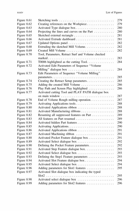
Figure 8.61 Sketching tools . . . . . . . . . . . . . . . . . . . . . . . . . . . . . . 279Figure 8.62 Creating references on the Workpiece . . . . . . . . . . . . . . . 279Figure 8.63 Activated Type dialogue box . . . . . . . . . . . . . . . . . . . . . 280Figure 8.64 Projecting the lines and curves on the Part . . . . . . . . . . . 280Figure 8.65 Sketched external rectangle . . . . . . . . . . . . . . . . . . . . . . 281Figure 8.66 Activated Extrude dashboard . . . . . . . . . . . . . . . . . . . . . 281Figure 8.67 Updated Options panel . . . . . . . . . . . . . . . . . . . . . . . . . 282Figure 8.68 Extruding the sketched Mill Volume. . . . . . . . . . . . . . . . 282Figure 8.69 Created Mill Volume . . . . . . . . . . . . . . . . . . . . . . . . . . 282Figure 8.70 Tool, Parameters, Retract Surf and Volume checked
marked . . . . . . . . . . . . . . . . . . . . . . . . . . . . . . . . . . . . 283Figure 8.71 T0006 highlighted as the cutting Tool. . . . . . . . . . . . . . . 284Figure 8.72 Activated Edit Parameters of Sequence ‘‘Volume
Milling’’ dialogue box . . . . . . . . . . . . . . . . . . . . . . . . . 284Figure 8.73 Edit Parameters of Sequence ‘‘Volume Milling’’
parameters. . . . . . . . . . . . . . . . . . . . . . . . . . . . . . . . . . 285Figure 8.74 Creating the Retract Setup parameters . . . . . . . . . . . . . . . 285Figure 8.75 Adding the created Mill Volume . . . . . . . . . . . . . . . . . . 286Figure 8.76 Play Path and Screen Play highlighted . . . . . . . . . . . . . . 286Figure 8.77 Activated cutting Tool and PLAY PATH dialogue box
on main window . . . . . . . . . . . . . . . . . . . . . . . . . . . . . 287Figure 8.78 End of Volume Rough milling operation. . . . . . . . . . . . . 287Figure 8.79 Activating Applications tools . . . . . . . . . . . . . . . . . . . . . 288Figure 8.80 Activated Applications ribbon . . . . . . . . . . . . . . . . . . . . 288Figure 8.81 Activated Manufacturing ribbons . . . . . . . . . . . . . . . . . . 288Figure 8.82 Resuming all suppressed features on Part . . . . . . . . . . . . 289Figure 8.83 All features on Part resumed . . . . . . . . . . . . . . . . . . . . . 289Figure 8.84 Activated hidden Part features . . . . . . . . . . . . . . . . . . . . 290Figure 8.85 Activating Applications. . . . . . . . . . . . . . . . . . . . . . . . . 290Figure 8.86 Activated Applications ribbon . . . . . . . . . . . . . . . . . . . . 291Figure 8.87 Activated Machining ribbon . . . . . . . . . . . . . . . . . . . . . 291Figure 8.88 Activated Pocket Feature dialogue box . . . . . . . . . . . . . . 291Figure 8.89 Activated Select dialogue box . . . . . . . . . . . . . . . . . . . . 292Figure 8.90 Defining the Pocket Feature parameters. . . . . . . . . . . . . . 292Figure 8.91 Activated Step Feature dialogue box. . . . . . . . . . . . . . . . 293Figure 8.92 Activated Select dialogue box . . . . . . . . . . . . . . . . . . . . 293Figure 8.93 Defining the Step1 Feature parameters . . . . . . . . . . . . . . 293Figure 8.94 Activated Slot Feature dialogue box . . . . . . . . . . . . . . . . 294Figure 8.95 Activated Select dialogue box . . . . . . . . . . . . . . . . . . . . 294Figure 8.96 Adding parameters for Slot1 features . . . . . . . . . . . . . . . 295Figure 8.97 Activated Slot dialogue box indicating the typed
Slot2 . . . . . . . . . . . . . . . . . . . . . . . . . . . . . . . . . . . . . 295Figure 8.98 Activated select dialogue box . . . . . . . . . . . . . . . . . . . . 296Figure 8.99 Adding parameters for Slot2 features . . . . . . . . . . . . . . . 296
xxxiv List of Figures

Figure 8.100 Drill Group dialogue box . . . . . . . . . . . . . . . . . . . . . . . 297Figure 8.101 Adding diameter to be drilled . . . . . . . . . . . . . . . . . . . . 298Figure 8.102 Activated Select hole diameter dialogue box . . . . . . . . . . 298Figure 8.103 Diameter automatically added into the Diameters
section box . . . . . . . . . . . . . . . . . . . . . . . . . . . . . . . . . 299Figure 8.104 Activating Create Toolpath on POCKET1 [OP010]
drop-down menu list. . . . . . . . . . . . . . . . . . . . . . . . . . . 300Figure 8.105 T0004 is added as the Cutting Tool . . . . . . . . . . . . . . . . 300Figure 8.106 Amount of material removal section . . . . . . . . . . . . . . . . 301Figure 8.107 Activating Tool Path Properties from Pocket Milling
dialogue window . . . . . . . . . . . . . . . . . . . . . . . . . . . . . 301Figure 8.108 Activated Tool Path Properties dialogue window . . . . . . . 302Figure 8.109 Spindle Speed parameters . . . . . . . . . . . . . . . . . . . . . . . 302Figure 8.110 Feed Rates parameters . . . . . . . . . . . . . . . . . . . . . . . . . 303Figure 8.111 Cut Control parameters . . . . . . . . . . . . . . . . . . . . . . . . . 304Figure 8.112 Activating Play Path on Pocket Milling dialogue
window. . . . . . . . . . . . . . . . . . . . . . . . . . . . . . . . . . . . 305Figure 8.113 Activated cutting Tool and PLAY PATH dialogue
box . . . . . . . . . . . . . . . . . . . . . . . . . . . . . . . . . . . . . . 305Figure 8.114 Pocket Milling operation highlighted in red colours . . . . . 306Figure 8.115 Activating Create Toolpath STEP1 [OP010]
operation. . . . . . . . . . . . . . . . . . . . . . . . . . . . . . . . . . . 306Figure 8.116 Activating the Step Milling operation Tool . . . . . . . . . . . 307Figure 8.117 Step Milling and Tool Path Properties dialogue
windows on the main dialogue window . . . . . . . . . . . . . 308Figure 8.118 Creating the Spindle Speed parameters . . . . . . . . . . . . . . 308Figure 8.119 Creating the Feed Rates parameters . . . . . . . . . . . . . . . . 309Figure 8.120 Creating the Cut Control parameters . . . . . . . . . . . . . . . . 309Figure 8.121 Activated cutting Tool and PLAY PATH dialogue
box . . . . . . . . . . . . . . . . . . . . . . . . . . . . . . . . . . . . . . 310Figure 8.122 Step Milling operation highlighted in red colour . . . . . . . 310Figure 8.123 Activating SLOT1 Milling Create Toolpath . . . . . . . . . . . 311Figure 8.124 Creating the Slot1 Milling cutting Tool. . . . . . . . . . . . . . 311Figure 8.125 Activated Tool Path Properties dialogue window . . . . . . . 312Figure 8.126 Spindle Speed parameters . . . . . . . . . . . . . . . . . . . . . . . 312Figure 8.127 Feed Rates parameters . . . . . . . . . . . . . . . . . . . . . . . . . 313Figure 8.128 Cut Control parameters . . . . . . . . . . . . . . . . . . . . . . . . . 313Figure 8.129 Activated cutting Tool and PLAY PATH dialogue
box . . . . . . . . . . . . . . . . . . . . . . . . . . . . . . . . . . . . . . 314Figure 8.130 End of Slot1 Milling operation . . . . . . . . . . . . . . . . . . . 314Figure 8.131 Activating Create Toolpath for Drilling operation . . . . . . . 315Figure 8.132 Drilling Strategy dialogue window . . . . . . . . . . . . . . . . . 315Figure 8.133 Activated Drilling Properties dialogue window. . . . . . . . . 316Figure 8.134 Spindle Speed parameters . . . . . . . . . . . . . . . . . . . . . . . 316
List of Figures xxxv

Figure 8.135 Feed Rates parameters . . . . . . . . . . . . . . . . . . . . . . . . . 317Figure 8.136 Activated drilling Tool and the PLAY PATH dialogue
box . . . . . . . . . . . . . . . . . . . . . . . . . . . . . . . . . . . . . . 317Figure 8.137 Activating Tool Path Player for the whole operations . . . . 318Figure 8.138 Activated Tool and the PLAY PATH dialogue box . . . . . 318Figure 8.139 End of Pocket, Step, Slots and Drilling operations . . . . . . 319Figure 8.140 Activating Output Tool Path on the Model Tree. . . . . . . . 320Figure 8.141 Activated Save a Copy dialogue window in concise
form . . . . . . . . . . . . . . . . . . . . . . . . . . . . . . . . . . . . . . 320Figure 8.142 Activated Save a Copy dialogue window in concise
form . . . . . . . . . . . . . . . . . . . . . . . . . . . . . . . . . . . . . . 321Figure 8.143 Activated PP OPTIONS Menu Manager dialogue
box . . . . . . . . . . . . . . . . . . . . . . . . . . . . . . . . . . . . . . 321Figure 8.144 Activated PP LIST Menu Manager dialogue box . . . . . . . 322Figure 8.145 Activated INFORMATION WINDOW in concise
form . . . . . . . . . . . . . . . . . . . . . . . . . . . . . . . . . . . . . . 322Figure 9.1 Activated New dialogue box . . . . . . . . . . . . . . . . . . . . . 330Figure 9.2 Selecting “mmns_mfg_nc” as the SI unit. . . . . . . . . . . . . 331Figure 9.3 The Open dialogue window in concise form . . . . . . . . . . 332Figure 9.4 Constraining the imported 3D Part . . . . . . . . . . . . . . . . . 332Figure 9.5 Activated Auto Workpiece Creation dashboard in
concise form . . . . . . . . . . . . . . . . . . . . . . . . . . . . . . . . 333Figure 9.6 Activated Options panel and the Automatic Workpiece
dimensions . . . . . . . . . . . . . . . . . . . . . . . . . . . . . . . . . 334Figure 9.7 Selected Workpiece references used in creating the
Coordinate System . . . . . . . . . . . . . . . . . . . . . . . . . . . . 335Figure 9.8 Corrcet Orientaions of the X, Y and Z axes on the
Workpiece. . . . . . . . . . . . . . . . . . . . . . . . . . . . . . . . . . 335Figure 9.9 Created ACS1 (Coordinate System) on the Model
Tree . . . . . . . . . . . . . . . . . . . . . . . . . . . . . . . . . . . . . . 336Figure 9.10 Activated WEDM Work Centre dialogue window . . . . . . 337Figure 9.11 Operation ribbon toolbar in concise form . . . . . . . . . . . . 338Figure 9.12 Activated Tools Setup dialogue window . . . . . . . . . . . . . 339Figure 9.13 Wire EDM cutting Tool parameters . . . . . . . . . . . . . . . . 340Figure 9.14 Checked Marked Tool and Parameters on SEQ SETUP
group . . . . . . . . . . . . . . . . . . . . . . . . . . . . . . . . . . . . . 341Figure 9.15 Activated Wire EDM cutting Tool . . . . . . . . . . . . . . . . . 342Figure 9.16 Activated Edit Parameters of Sequence “Contouring
Wire EDM” dialogue window . . . . . . . . . . . . . . . . . . . . 343Figure 9.17 Wire EDM parameters . . . . . . . . . . . . . . . . . . . . . . . . . 344Figure 9.18 Activated Customize dialogue box . . . . . . . . . . . . . . . . . 345Figure 9.19 WEDM OPT Menu Manager dialogue box with Sketch
highlighted and Rough check marked . . . . . . . . . . . . . . . 345Figure 9.20 Activated INT CUT Menu Manager dialogue box . . . . . . 346
xxxvi List of Figures
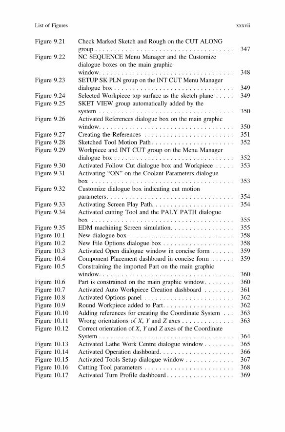
Figure 9.21 Check Marked Sketch and Rough on the CUT ALONGgroup . . . . . . . . . . . . . . . . . . . . . . . . . . . . . . . . . . . . . 347
Figure 9.22 NC SEQUENCE Menu Manager and the Customizedialogue boxes on the main graphicwindow. . . . . . . . . . . . . . . . . . . . . . . . . . . . . . . . . . . . 348
Figure 9.23 SETUP SK PLN group on the INT CUT Menu Managerdialogue box . . . . . . . . . . . . . . . . . . . . . . . . . . . . . . . . 349
Figure 9.24 Selected Workpiece top surface as the sketch plane . . . . . 349Figure 9.25 SKET VIEW group automatically added by the
system . . . . . . . . . . . . . . . . . . . . . . . . . . . . . . . . . . . . 350Figure 9.26 Activated References dialogue box on the main graphic
window. . . . . . . . . . . . . . . . . . . . . . . . . . . . . . . . . . . . 350Figure 9.27 Creating the References . . . . . . . . . . . . . . . . . . . . . . . . 351Figure 9.28 Sketched Tool Motion Path . . . . . . . . . . . . . . . . . . . . . . 352Figure 9.29 Workpiece and INT CUT group on the Menu Manager
dialogue box . . . . . . . . . . . . . . . . . . . . . . . . . . . . . . . . 352Figure 9.30 Activated Follow Cut dialogue box and Workpiece . . . . . 353Figure 9.31 Activating “ON” on the Coolant Parameters dialogue
box . . . . . . . . . . . . . . . . . . . . . . . . . . . . . . . . . . . . . . 353Figure 9.32 Customize dialogue box indicating cut motion
parameters. . . . . . . . . . . . . . . . . . . . . . . . . . . . . . . . . . 354Figure 9.33 Activating Screen Play Path. . . . . . . . . . . . . . . . . . . . . . 354Figure 9.34 Activated cutting Tool and the PALY PATH dialogue
box . . . . . . . . . . . . . . . . . . . . . . . . . . . . . . . . . . . . . . 355Figure 9.35 EDM machining Screen simulation. . . . . . . . . . . . . . . . . 355Figure 10.1 New dialogue box . . . . . . . . . . . . . . . . . . . . . . . . . . . . 358Figure 10.2 New File Options dialogue box . . . . . . . . . . . . . . . . . . . 358Figure 10.3 Activated Open dialogue window in concise form . . . . . . 359Figure 10.4 Component Placement dashboard in concise form . . . . . . 359Figure 10.5 Constraining the imported Part on the main graphic
window. . . . . . . . . . . . . . . . . . . . . . . . . . . . . . . . . . . . 360Figure 10.6 Part is constrained on the main graphic window. . . . . . . . 360Figure 10.7 Activated Auto Workpiece Creation dashboard . . . . . . . . 361Figure 10.8 Activated Options panel . . . . . . . . . . . . . . . . . . . . . . . . 362Figure 10.9 Round Workpiece added to Part. . . . . . . . . . . . . . . . . . . 362Figure 10.10 Adding references for creating the Coordinate System . . . 363Figure 10.11 Wrong orientations of X, Y and Z axes . . . . . . . . . . . . . . 363Figure 10.12 Correct orientation of X, Y and Z axes of the Coordinate
System . . . . . . . . . . . . . . . . . . . . . . . . . . . . . . . . . . . . 364Figure 10.13 Activated Lathe Work Centre dialogue window . . . . . . . . 365Figure 10.14 Activated Operation dashboard. . . . . . . . . . . . . . . . . . . . 366Figure 10.15 Activated Tools Setup dialogue window . . . . . . . . . . . . . 367Figure 10.16 Cutting Tool parameters . . . . . . . . . . . . . . . . . . . . . . . . 368Figure 10.17 Activated Turn Profile dashboard . . . . . . . . . . . . . . . . . . 369
List of Figures xxxvii

Figure 10.18 Adding the Plament parameters . . . . . . . . . . . . . . . . . . . 369Figure 10.19 Activating Turn Profile sketch . . . . . . . . . . . . . . . . . . . . 369Figure 10.20 Activating Define an Internal Sketch . . . . . . . . . . . . . . . 369Figure 10.21 Activated Sketch dialogue box. . . . . . . . . . . . . . . . . . . . 370Figure 10.22 Activated Sketch tools . . . . . . . . . . . . . . . . . . . . . . . . . 370Figure 10.23 Adding references for the Turn Profile sketch . . . . . . . . . 371Figure 10.24 Sketching start point for the cutting Tool . . . . . . . . . . . . 371Figure 10.25 Activated Type dialogue box . . . . . . . . . . . . . . . . . . . . . 372Figure 10.26 Projecting Lines and Curve into the sketch plane . . . . . . . 372Figure 10.27 Connecting the projected Lines and Curve. . . . . . . . . . . . 373Figure 10.28 Turn Profile lines and direction activated . . . . . . . . . . . . 373Figure 10.29 Activated Area Turning dashboard indicating T0001
and ACS1 . . . . . . . . . . . . . . . . . . . . . . . . . . . . . . . . . . 374Figure 10.30 Activated Parameters panel . . . . . . . . . . . . . . . . . . . . . . 375Figure 10.31 Activated Turning Tool and PLAY PATH dialogue
box . . . . . . . . . . . . . . . . . . . . . . . . . . . . . . . . . . . . . . 376Figure 10.32 End of on-screen Area Turning operation . . . . . . . . . . . . 376Figure 10.33 Area Area Turning parameters . . . . . . . . . . . . . . . . . . . . 377Figure 10.34 Activating Area Turning Cut from Tool Motions
panel . . . . . . . . . . . . . . . . . . . . . . . . . . . . . . . . . . . . . 378Figure 10.35 Activated Area Turning dialogue box . . . . . . . . . . . . . . . 378Figure 10.36 Adding the created Turning Profile into the Area
Turning Cut dialogue box . . . . . . . . . . . . . . . . . . . . . . . 379Figure 10.37 Area Turning Cut parameters indicating positive
Z and X . . . . . . . . . . . . . . . . . . . . . . . . . . . . . . . . . . . 379Figure 10.38 Area Turning indicating the created Tool Motions
parameters. . . . . . . . . . . . . . . . . . . . . . . . . . . . . . . . . . 380Figure 10.39 Activated cutting Tool and PLAY PATH dialogue
box . . . . . . . . . . . . . . . . . . . . . . . . . . . . . . . . . . . . . . 381Figure 10.40 End of Area Turning operation . . . . . . . . . . . . . . . . . . . 381Figure 10.41 End of Area Turning Material Removal Simulation . . . . . 382Figure 10.42 Activated SELECT FEAT Menu Manager dialogue
box . . . . . . . . . . . . . . . . . . . . . . . . . . . . . . . . . . . . . . 383Figure 10.43 Activated PATH Menu Manager dialogue box. . . . . . . . . 383Figure 10.44 Activated Save a Copy dialogue window in concise
form . . . . . . . . . . . . . . . . . . . . . . . . . . . . . . . . . . . . . . 384Figure 10.45 Activating Done Output on the PATH group . . . . . . . . . . 384Figure 10.46 Activating Open dialogue window . . . . . . . . . . . . . . . . . 385Figure 10.47 Activated PP OPTIONS Menu Manager dialogue
box . . . . . . . . . . . . . . . . . . . . . . . . . . . . . . . . . . . . . . 385Figure 10.48 Activated PP LIST Menu Manager dialogue box . . . . . . . 386Figure 10.49 Activated INFORMATION WINDOW in concise
form . . . . . . . . . . . . . . . . . . . . . . . . . . . . . . . . . . . . . . 386
xxxviii List of Figures
Figure 11.1 Activating Manufacturing application on the Newdialogue box . . . . . . . . . . . . . . . . . . . . . . . . . . . . . . . . 390
Figure 11.2 New File Options dialogue box . . . . . . . . . . . . . . . . . . . 390Figure 11.3 Activated Open dialogue window in concise form . . . . . . 391Figure 11.4 Activated Component Placement dashboard . . . . . . . . . . . 391Figure 11.5 Constraining the imported 3D Part . . . . . . . . . . . . . . . . . 392Figure 11.6 Imported Part is fully constrained. . . . . . . . . . . . . . . . . . 392Figure 11.7 Activated Auto Workpiece Creation ribbon toolbar. . . . . . 393Figure 11.8 Activated Options Panel showing Workpiece
dimensions . . . . . . . . . . . . . . . . . . . . . . . . . . . . . . . . . 393Figure 11.9 Round Workpiece added to 3D Part . . . . . . . . . . . . . . . . 394Figure 11.10 Adding references for the Coordinate System creation . . . 394Figure 11.11 Wrong orientations of the X, Y and Z axes of the
Coordinate System . . . . . . . . . . . . . . . . . . . . . . . . . . . . 395Figure 11.12 Correct orientation of the X, Y and Z axes of the
Coordinate System . . . . . . . . . . . . . . . . . . . . . . . . . . . . 396Figure 11.13 ACS1 renamed as PZ01 on the Model Tree. . . . . . . . . . . 396Figure 11.14 Activated Lathe Work Centre dialogue window . . . . . . . . 397Figure 11.15 LATHE01 and PZ01 are automatically generated and
added . . . . . . . . . . . . . . . . . . . . . . . . . . . . . . . . . . . . . 398Figure 11.16 Clearance panel with Retract parameters . . . . . . . . . . . . . 398Figure 11.17 Activating Clearance panel and Retract plane
parameter . . . . . . . . . . . . . . . . . . . . . . . . . . . . . . . . . . 399Figure 11.18 Activated Tools Setup dialogue window . . . . . . . . . . . . . 400Figure 11.19 Turning Tool parameters . . . . . . . . . . . . . . . . . . . . . . . . 401Figure 11.20 Drilling Tool (T0002) and Turning Tool (T0003)
parameters. . . . . . . . . . . . . . . . . . . . . . . . . . . . . . . . . . 402Figure 11.21 Activated Datum Point dialogue box. . . . . . . . . . . . . . . . 403Figure 11.22 Reference and Type parameters added to the Datum
Point dialogue box . . . . . . . . . . . . . . . . . . . . . . . . . . . . 404Figure 11.23 Name and values added to the X, Y and Z axes cells . . . . 404Figure 11.24 Created Datum Point . . . . . . . . . . . . . . . . . . . . . . . . . . 405Figure 11.25 Activated Turn Profile dashboard . . . . . . . . . . . . . . . . . . 405Figure 11.26 Adding PZ01 as the Placement Csys reference. . . . . . . . . 406Figure 11.27 Activating Use sketch to define turn profile . . . . . . . . . . . 406Figure 11.28 Activating Define an Internal Sketch . . . . . . . . . . . . . . . 406Figure 11.29 Activated Sketch dialogue box with all Sketching
parameters. . . . . . . . . . . . . . . . . . . . . . . . . . . . . . . . . . 407Figure 11.30 Activated Sketch tools in concise form . . . . . . . . . . . . . . 407Figure 11.31 Activated References dialogue box . . . . . . . . . . . . . . . . . 408Figure 11.32 Adding References . . . . . . . . . . . . . . . . . . . . . . . . . . . . 408Figure 11.33 Activated Type dialogue box . . . . . . . . . . . . . . . . . . . . . 409Figure 11.34 Projecting Lines into the sketch plane . . . . . . . . . . . . . . . 409Figure 11.35 Joining all the projected Lines together . . . . . . . . . . . . . . 410
List of Figures xxxix
Figure 11.36 Activated Start and End direction of Turn Profile . . . . . . . 410Figure 11.37 Activated Area Turning dashboard in concise form. . . . . . 411Figure 11.38 Area Turning parameters and the system activated
cutting area . . . . . . . . . . . . . . . . . . . . . . . . . . . . . . . . . 412Figure 11.39 Activated Tool Motions panel . . . . . . . . . . . . . . . . . . . . 412Figure 11.40 Activated Area Turning Cut dialogue window . . . . . . . . . 413Figure 11.41 Highlighted Turn Profile Model Tree . . . . . . . . . . . . . . . 413Figure 11.42 Area Turning Cut parameters . . . . . . . . . . . . . . . . . . . . . 414Figure 11.43 Activated cutting Tool and PLAY PATH dialogue
box . . . . . . . . . . . . . . . . . . . . . . . . . . . . . . . . . . . . . . 415Figure 11.44 End of the Area Turning operation . . . . . . . . . . . . . . . . . 415Figure 11.45 Activated Drilling dashboard in concise form. . . . . . . . . . 416Figure 11.46 Drilling parameters values on the activated Parameters
panel . . . . . . . . . . . . . . . . . . . . . . . . . . . . . . . . . . . . . 416Figure 11.47 Adding the Drilling reference parameters. . . . . . . . . . . . . 417Figure 11.48 Adding Clearance parameters. . . . . . . . . . . . . . . . . . . . . 418Figure 11.49 Activated Drilling Tool and PLAY PATH dialogue
box . . . . . . . . . . . . . . . . . . . . . . . . . . . . . . . . . . . . . . 418Figure 11.50 Changing the Retract Start and End Points group
parameters. . . . . . . . . . . . . . . . . . . . . . . . . . . . . . . . . . 419Figure 11.51 Activated Drilling Tool and the PLAY PATH dialogue
box with Tool staring at the created Datum point . . . . . . . 420Figure 11.52 End of on-screen Drilling operation . . . . . . . . . . . . . . . . 420Figure 11.53 Activated Turn Profile dashboard . . . . . . . . . . . . . . . . . . 421Figure 11.54 Adding the Placement reference . . . . . . . . . . . . . . . . . . . 421Figure 11.55 Activating Use sketch to define turn profile . . . . . . . . . . . 421Figure 11.56 Activating Define an Internal Sketch . . . . . . . . . . . . . . . 422Figure 11.57 Activated Sketch dialogue box. . . . . . . . . . . . . . . . . . . . 422Figure 11.58 Activated Sketch tools . . . . . . . . . . . . . . . . . . . . . . . . . 422Figure 11.59 Activating Wireframe on the Display Style drop-down
list . . . . . . . . . . . . . . . . . . . . . . . . . . . . . . . . . . . . . . . 423Figure 11.60 Workpiece in Wireframe display style. . . . . . . . . . . . . . . 423Figure 11.61 Creating references for the internal diameter . . . . . . . . . . 423Figure 11.62 Activated Type dialogue box . . . . . . . . . . . . . . . . . . . . . 424Figure 11.63 Projecting the internal horizontal line inside the hole. . . . . 424Figure 11.64 Wrong Tool cut direction . . . . . . . . . . . . . . . . . . . . . . . 425Figure 11.65 Correct orientation of the START and END arrows in
purple colour . . . . . . . . . . . . . . . . . . . . . . . . . . . . . . . . 426Figure 11.66 Activated Area Turning dashboard . . . . . . . . . . . . . . . . . 426Figure 11.67 Area Turning parameters . . . . . . . . . . . . . . . . . . . . . . . . 427Figure 11.68 Activating Area Turning Cut . . . . . . . . . . . . . . . . . . . . . 427Figure 11.69 Activated Area Turning Cut dialogue window . . . . . . . . . 428Figure 11.70 Activating the created Turn Profile 2 [Turn Profile] . . . . . 428Figure 11.71 Defining Area Turning Cut parameters . . . . . . . . . . . . . . 429
xl List of Figures
Figure 11.72 Activated cutting Tool and the PLAY PATH dialoguebox . . . . . . . . . . . . . . . . . . . . . . . . . . . . . . . . . . . . . . 430
Figure 11.73 End of Area Turning operation in wireframe display. . . . . 430Figure 11.74 Activating the correct Coordinate System orientation . . . . 431Figure 11.75 Correct orientation of X, Y and Z axes of the Coordinate
System . . . . . . . . . . . . . . . . . . . . . . . . . . . . . . . . . . . . 432Figure 11.76 Model Tree indicating the renamed PZ02 . . . . . . . . . . . . 432Figure 11.77 Activated Milling Work Centre dialogue window . . . . . . . 433Figure 11.78 The New created ADTM1 datum plane. . . . . . . . . . . . . . 434Figure 11.79 MILL01 and PZ02 in there respective section boxes. . . . . 434Figure 11.80 Clearance panel parameters and created retract plane . . . . 435Figure 11.81 Activated Mill Volume dashboard . . . . . . . . . . . . . . . . . 435Figure 11.82 Activated Extrude dashboard . . . . . . . . . . . . . . . . . . . . . 436Figure 11.83 Activated Placement panel. . . . . . . . . . . . . . . . . . . . . . . 436Figure 11.84 Activated Sketch dialogue box. . . . . . . . . . . . . . . . . . . . 436Figure 11.85 Activated Sketch tools . . . . . . . . . . . . . . . . . . . . . . . . . 437Figure 11.86 Activated Type dialogue box . . . . . . . . . . . . . . . . . . . . . 437Figure 11.87 Projecting the lines into the Sketch plane . . . . . . . . . . . . 438Figure 11.88 Creating the Mill Volume via extrusion . . . . . . . . . . . . . 439Figure 11.89 Created Mill Volume . . . . . . . . . . . . . . . . . . . . . . . . . . 439Figure 11.90 Activated NC SEQUENCE Menu Manager dialogue
box . . . . . . . . . . . . . . . . . . . . . . . . . . . . . . . . . . . . . . 440Figure 11.91 Created END MILL Tool (T0004) . . . . . . . . . . . . . . . . . 441Figure 11.92 Parameter values for Volume Rough milling
operation. . . . . . . . . . . . . . . . . . . . . . . . . . . . . . . . . . . 442Figure 11.93 Activating on-screen Volume Rough milling
operation. . . . . . . . . . . . . . . . . . . . . . . . . . . . . . . . . . . 443Figure 11.94 Activated PLAY PATH dialogue box and cutting
Tool . . . . . . . . . . . . . . . . . . . . . . . . . . . . . . . . . . . . . . 444Figure 11.95 End of the Volume Rough milling operation in
Wireframe . . . . . . . . . . . . . . . . . . . . . . . . . . . . . . . . . . 444Figure 11.96 Activated NC CHECK and NC DISP groups . . . . . . . . . . 445Figure 11.97 Activated Material Removal Simulation process . . . . . . . . 446Figure 11.98 Activated SELECT FEAT and SEL MENU group . . . . . . 447Figure 11.99 Activated PATH Menu Manager dialogue box. . . . . . . . . 447Figure 11.100 Save a Copy dialogue window in concise form . . . . . . . . 448Figure 11.101 Activating Done Output on the PATH group . . . . . . . . . . 448Figure 11.102 Activated Open dialogue window in concise form . . . . . . 449Figure 11.103 Activated PP OPTIONS group with Verbose and Trace
check marked . . . . . . . . . . . . . . . . . . . . . . . . . . . . . . . 449Figure 11.104 Activated PP LIST Menu Manager dialogue box . . . . . . . 450Figure 11.105 Activated INFORMATION WINDOW in concise
form. . . . . . . . . . . . . . . . . . . . . . . . . . . . . . . . . . . . . . 451Figure 12.1 Activating the Manufacturing application . . . . . . . . . . . . 456
List of Figures xli
Figure 12.2 New File Options parameters . . . . . . . . . . . . . . . . . . . . . 457Figure 12.3 Activated Component Placement dashboard . . . . . . . . . . . 458Figure 12.4 Constraining the imported Part. . . . . . . . . . . . . . . . . . . . 458Figure 12.5 Part now constrained on the main manufacturing GUI
window. . . . . . . . . . . . . . . . . . . . . . . . . . . . . . . . . . . . 459Figure 12.6 Activated Auto Workpiece Creation dashboard . . . . . . . . 459Figure 12.7 Activated Options Panel showing Wokpiece
dimensions . . . . . . . . . . . . . . . . . . . . . . . . . . . . . . . . . 460Figure 12.8 Stock now added to Part . . . . . . . . . . . . . . . . . . . . . . . . 460Figure 12.9 Holes on Part now suppressed . . . . . . . . . . . . . . . . . . . . 461Figure 12.10 Coordinate System dialogue box . . . . . . . . . . . . . . . . . . 462Figure 12.11 Creating the Coordinate System . . . . . . . . . . . . . . . . . . . 462Figure 12.12 Correct orientations of X, Y and Z axes of Coordinate
System . . . . . . . . . . . . . . . . . . . . . . . . . . . . . . . . . . . . 463Figure 12.13 Creating Coordinate System on the Workpiece
bottom . . . . . . . . . . . . . . . . . . . . . . . . . . . . . . . . . . . . 464Figure 12.14 Correct orientation of X, Y and Z axes of the bottom
Coordinate System . . . . . . . . . . . . . . . . . . . . . . . . . . . . 464Figure 12.15 Activated Milling Work Centre dialogue window . . . . . . . 466Figure 12.16 Adding the Clearance parameters for the Retract
plane . . . . . . . . . . . . . . . . . . . . . . . . . . . . . . . . . . . . . 467Figure 12.17 ACS2, ACS3, MILL01 and OP010 [MILL01] on Model
Tree . . . . . . . . . . . . . . . . . . . . . . . . . . . . . . . . . . . . . . 468Figure 12.18 T01 dimensions . . . . . . . . . . . . . . . . . . . . . . . . . . . . . . 469Figure 12.19 T02 dimensions . . . . . . . . . . . . . . . . . . . . . . . . . . . . . . 470Figure 12.20 T03 dimensions . . . . . . . . . . . . . . . . . . . . . . . . . . . . . . 471Figure 12.21 T04 dimensions . . . . . . . . . . . . . . . . . . . . . . . . . . . . . . 472Figure 12.22 T05 dimensions . . . . . . . . . . . . . . . . . . . . . . . . . . . . . . 473Figure 12.23 T06 dimensions . . . . . . . . . . . . . . . . . . . . . . . . . . . . . . 474Figure 12.24 T07 dimensions . . . . . . . . . . . . . . . . . . . . . . . . . . . . . . 475Figure 12.25 T08 dimensions . . . . . . . . . . . . . . . . . . . . . . . . . . . . . . 476Figure 12.26 Activated Mill Volume dashboard tools . . . . . . . . . . . . . 477Figure 12.27 Activated Sketch dialogue box. . . . . . . . . . . . . . . . . . . . 478Figure 12.28 Creating sketch Plane references . . . . . . . . . . . . . . . . . . 478Figure 12.29 Activated Sketch tools in concise form . . . . . . . . . . . . . . 479Figure 12.30 Workpiece in correct orientation on the sketch plane . . . . 479Figure 12.31 Creating the references . . . . . . . . . . . . . . . . . . . . . . . . . 480Figure 12.32 Activated Type dialogue box . . . . . . . . . . . . . . . . . . . . . 480Figure 12.33 Projecting Lines and Curves into the sketch plane . . . . . . 481Figure 12.34 Activated Extrude dashboard . . . . . . . . . . . . . . . . . . . . . 481Figure 12.35 Creating the first top mill volume. . . . . . . . . . . . . . . . . . 482Figure 12.36 First top created mill volume . . . . . . . . . . . . . . . . . . . . . 482Figure 12.37 Activated NC SEQUENCE Menu Manager dialogue
box . . . . . . . . . . . . . . . . . . . . . . . . . . . . . . . . . . . . . . 483
xlii List of Figures

Figure 12.38 Activating T01 as the milling Tool in concise form . . . . . 484Figure 12.39 Activated Edit Parameters of Sequence “Volume
Milling’’ dialogue window . . . . . . . . . . . . . . . . . . . . . . 485Figure 12.40 Parameters for Volume Roughing milling operation . . . . . 486Figure 12.41 Adding the top first created mill volume . . . . . . . . . . . . . 487Figure 12.42 Activated cutting Tool and PLAY PATH dialogue
box . . . . . . . . . . . . . . . . . . . . . . . . . . . . . . . . . . . . . . 487Figure 12.43 Cutting Tool and Workpiece in Wireframe display . . . . . . 488Figure 12.44 End of Volume Rough milling operation in Wireframe
display . . . . . . . . . . . . . . . . . . . . . . . . . . . . . . . . . . . . 489Figure 12.45 Activated Mill Volume dashboard in concise form . . . . . . 490Figure 12.46 Activating the sketch plane . . . . . . . . . . . . . . . . . . . . . . 490Figure 12.47 Activated Sketch tools in concise form . . . . . . . . . . . . . . 491Figure 12.48 Workpiece in correct orientation on the sketch plane . . . . 491Figure 12.49 Activated Type dialogue box . . . . . . . . . . . . . . . . . . . . . 492Figure 12.50 Sketched Mill Volume highlighted . . . . . . . . . . . . . . . . . 492Figure 12.51 Selecting Extrude to selected point, curve, plane
or surface extrusion option type . . . . . . . . . . . . . . . . . . . 493Figure 12.52 Extruding the sketched Mill Volume to the next
surface . . . . . . . . . . . . . . . . . . . . . . . . . . . . . . . . . . . . 493Figure 12.53 Second created Mill Volume . . . . . . . . . . . . . . . . . . . . . 494Figure 12.54 Activated NC SEQUENCE Menu Manager dialogue
box . . . . . . . . . . . . . . . . . . . . . . . . . . . . . . . . . . . . . . 495Figure 12.55 Activated Tools Setup dialogue window with T02
selected. . . . . . . . . . . . . . . . . . . . . . . . . . . . . . . . . . . . 496Figure 12.56 Volume Rough milling parameters for the second mill
volume . . . . . . . . . . . . . . . . . . . . . . . . . . . . . . . . . . . . 497Figure 12.57 Activated Retract plane and Retract Setup dialogue
box . . . . . . . . . . . . . . . . . . . . . . . . . . . . . . . . . . . . . . 497Figure 12.58 Adding the second mill volume as the volume to be
milled . . . . . . . . . . . . . . . . . . . . . . . . . . . . . . . . . . . . . 498Figure 12.59 Activating Play Path and on Screen Play. . . . . . . . . . . . . 498Figure 12.60 Activated cutting Tool and PLAY PATH dialogue
box . . . . . . . . . . . . . . . . . . . . . . . . . . . . . . . . . . . . . . 499Figure 12.61 End of Volume Rough milling operation in Wireframe
display . . . . . . . . . . . . . . . . . . . . . . . . . . . . . . . . . . . . 499Figure 12.62 Activated Mill Volume ribbon toolbar. . . . . . . . . . . . . . . 500Figure 12.63 Updated Sketch dialogue box . . . . . . . . . . . . . . . . . . . . 500Figure 12.64 Activated Sketch tools in concise form . . . . . . . . . . . . . . 501Figure 12.65 Workpiece in correct orientation. . . . . . . . . . . . . . . . . . . 501Figure 12.66 Activated Type dialogue box . . . . . . . . . . . . . . . . . . . . . 502Figure 12.67 Projecting Lines and Curves into the sketch plane . . . . . . 502Figure 12.68 Activated Extrude dashboard . . . . . . . . . . . . . . . . . . . . . 503Figure 12.69 Extruding the created third mill volume . . . . . . . . . . . . . 503
List of Figures xliii
Figure 12.70 Tool, Parameters and Volume check marked on theSEQ SETUP group . . . . . . . . . . . . . . . . . . . . . . . . . . . 504
Figure 12.71 Parameters for Volume Rough milling operation . . . . . . . 505Figure 12.72 Activating Play Path and on Screen Play. . . . . . . . . . . . . 505Figure 12.73 End of Volume Rough milling operation. . . . . . . . . . . . . 506Figure 12.74 Activated Mill Volume dashboard in concise form . . . . . . 506Figure 12.75 Creating the Sketch plane reference . . . . . . . . . . . . . . . . 507Figure 12.76 Activated Sketch tools . . . . . . . . . . . . . . . . . . . . . . . . . 507Figure 12.77 Workpiece on correct orientation . . . . . . . . . . . . . . . . . . 508Figure 12.78 Activated Type dialogue box . . . . . . . . . . . . . . . . . . . . . 508Figure 12.79 Projecting the lines into the sketch plane. . . . . . . . . . . . . 509Figure 12.80 ‘‘Extrude to selected point, curve, plane or surface’’
option type . . . . . . . . . . . . . . . . . . . . . . . . . . . . . . . . . 509Figure 12.81 Extruding the created Mill Volume to the next
surface . . . . . . . . . . . . . . . . . . . . . . . . . . . . . . . . . . . . 510Figure 12.82 NC SEQUENCE Menu Manager dialogue box with
Tool, Parameters and Volume checked marked . . . . . . . . 511Figure 12.83 Activating Tool T02 for the fourth Mill Volume . . . . . . . 512Figure 12.84 Parameters for Volume Rough milling operation . . . . . . . 513Figure 12.85 Fourth Mill Volume for the milling operation . . . . . . . . . 513Figure 12.86 Activating Play Path . . . . . . . . . . . . . . . . . . . . . . . . . . . 514Figure 12.87 Activating on Screen Play . . . . . . . . . . . . . . . . . . . . . . . 514Figure 12.88 End of Volume Rough milling operation. . . . . . . . . . . . . 515Figure 12.89 Activated Mill Volume dashboard in concise form . . . . . . 515Figure 12.90 Activating the sketch plane . . . . . . . . . . . . . . . . . . . . . . 516Figure 12.91 Activated Sketch tools in concise form . . . . . . . . . . . . . . 516Figure 12.92 Correct orientation of Workpiece Stock. . . . . . . . . . . . . . 517Figure 12.93 Activated Type dialogue box . . . . . . . . . . . . . . . . . . . . . 517Figure 12.94 Projected circular sketch . . . . . . . . . . . . . . . . . . . . . . . . 518Figure 12.95 Activating Extrude to selected point, curve, plane or
surface extrusion option type . . . . . . . . . . . . . . . . . . . . . 518Figure 12.96 Extruding the sketched mill volume . . . . . . . . . . . . . . . . 519Figure 12.97 Tool, Parameters and Volume check marked . . . . . . . . . . 520Figure 12.98 Selected fifth Volume Rough mill Tool (T03) . . . . . . . . . 521Figure 12.99 Parameters for Volume Rough milling operation . . . . . . . 522Figure 12.100 Activating Play Path and on Screen Play. . . . . . . . . . . . . 522Figure 12.101 Activated cutting Tool and the PLAY PATH dialogue
box . . . . . . . . . . . . . . . . . . . . . . . . . . . . . . . . . . . . . . 523Figure 12.102 End of Volume Rough milling operation in Wireframe
display . . . . . . . . . . . . . . . . . . . . . . . . . . . . . . . . . . . . 523Figure 12.103 Operation parameters for the bottom Volume Rough
milling operations . . . . . . . . . . . . . . . . . . . . . . . . . . . . 524Figure 12.104 Creating the Retract plane for the bottom milling
operations . . . . . . . . . . . . . . . . . . . . . . . . . . . . . . . . . . 525
xliv List of Figures

Figure 12.105 Activated Mill Volume dashboar in concise form . . . . . . . 525Figure 12.106 Activating the Sketch plane . . . . . . . . . . . . . . . . . . . . . . 526Figure 12.107 Activated Sketch tools in concise form . . . . . . . . . . . . . . 526Figure 12.108 Activated Type dialogue box . . . . . . . . . . . . . . . . . . . . . 526Figure 12.109 Projecting Lines and Curves into the Sketch plane . . . . . . 527Figure 12.110 Activating the Extrude to selected point, curve, plane or
surface option . . . . . . . . . . . . . . . . . . . . . . . . . . . . . . . 527Figure 12.111 Extruding the sketch to the next surafce . . . . . . . . . . . . . 528Figure 12.112 Created first bottom mill volume . . . . . . . . . . . . . . . . . . 528Figure 12.113 Tool, Parameters, Retract Surf and Volume checked
marked on SEQ SETUP group. . . . . . . . . . . . . . . . . . . . 529Figure 12.114 Correct Tool for the first bottom Volume Rough milling
operation. . . . . . . . . . . . . . . . . . . . . . . . . . . . . . . . . . . 530Figure 12.115 Volume Rough milling parameters . . . . . . . . . . . . . . . . . 530Figure 12.116 Activated Retract Setup dialogue box and plane . . . . . . . . 531Figure 12.117 Activating Play Path and Screen Play . . . . . . . . . . . . . . . 531Figure 12.118 Activated PLAY PATH dialogue box and cutting
Tool . . . . . . . . . . . . . . . . . . . . . . . . . . . . . . . . . . . . . . 532Figure 12.119 Activated Mill Volume dashboard in concise form . . . . . . 532Figure 12.120 Activating the Sketch plane . . . . . . . . . . . . . . . . . . . . . . 533Figure 12.121 Activated Sketch tools in concise form . . . . . . . . . . . . . . 533Figure 12.122 Correct orientation of Workpiece . . . . . . . . . . . . . . . . . . 533Figure 12.123 Activated Type dialogue box . . . . . . . . . . . . . . . . . . . . . 534Figure 12.124 Projecting Lines on the Workpiece into the Sketch
plane . . . . . . . . . . . . . . . . . . . . . . . . . . . . . . . . . . . . . 534Figure 12.125 Activating Extrude to selected point, curve, plane or
surface extrusion option type . . . . . . . . . . . . . . . . . . . . . 535Figure 12.126 Extruding the sketch to the next surafce . . . . . . . . . . . . . 535Figure 12.127 Created second right bottom Mill Volume . . . . . . . . . . . . 536Figure 12.128 Tool, Parameters, Retract Surf and Volume check
marked . . . . . . . . . . . . . . . . . . . . . . . . . . . . . . . . . . . . 537Figure 12.129 Activating Tool (T02) as the correct cutting Tool . . . . . . . 538Figure 12.130 Volume Rough milling parameters . . . . . . . . . . . . . . . . . 538Figure 12.131 Activated Retract Setup dialogue box . . . . . . . . . . . . . . . 539Figure 12.132 Activating Play Path and on Screen Play. . . . . . . . . . . . . 539Figure 12.133 Activated cutting Tool and the PLAY PATH dialogue
box . . . . . . . . . . . . . . . . . . . . . . . . . . . . . . . . . . . . . . 540Figure 12.134 Activated Mill Volume dashboard tools in concise
form . . . . . . . . . . . . . . . . . . . . . . . . . . . . . . . . . . . . . . 540Figure 12.135 Activated Sketch tools in concise form . . . . . . . . . . . . . . 541Figure 12.136 Activated Type dialogue box . . . . . . . . . . . . . . . . . . . . . 541Figure 12.137 Projecting sketch Lines on the Workpiece into the
Sketch plane . . . . . . . . . . . . . . . . . . . . . . . . . . . . . . . . 542Figure 12.138 Activating Extrude to selected point, curve, plane or
surface extrusion type . . . . . . . . . . . . . . . . . . . . . . . . . . 542
List of Figures xlv
Figure 12.139 Created third bottom Mill Volume . . . . . . . . . . . . . . . . . 543Figure 12.140 Tool, Parameters and Volume check marked on
SEQ SETUP group . . . . . . . . . . . . . . . . . . . . . . . . . . . 544Figure 12.141 Parameters for Volume Rough milling . . . . . . . . . . . . . . 544Figure 12.142 Activating on Screen Play . . . . . . . . . . . . . . . . . . . . . . . 545Figure 12.143 Activated cutting Tool and PLAY PATH dialogue
box . . . . . . . . . . . . . . . . . . . . . . . . . . . . . . . . . . . . . . 545Figure 12.144 Activated Mill Volume ribbon toolbar. . . . . . . . . . . . . . . 546Figure 12.145 Sketch dialogue box after activating the sketch plane . . . . 546Figure 12.146 Activated Sketch ribbon/tools . . . . . . . . . . . . . . . . . . . . 547Figure 12.147 Activated Type dialogue box . . . . . . . . . . . . . . . . . . . . . 547Figure 12.148 Projecting Lines on Workpiece into the Sketch plane . . . . 547Figure 12.149 Activating Extrude to selected point, curve, plane or
surface extrusion option type . . . . . . . . . . . . . . . . . . . . . 548Figure 12.150 Extruding created sketch to the next surafce . . . . . . . . . . 548Figure 12.151 Tool, Parameters and Volume check marked on the
SEQ SETUP group . . . . . . . . . . . . . . . . . . . . . . . . . . . 549Figure 12.152 Parameter values for the Volume Rough milling
operation. . . . . . . . . . . . . . . . . . . . . . . . . . . . . . . . . . . 550Figure 12.153 Activating on Screen Play . . . . . . . . . . . . . . . . . . . . . . . 551Figure 12.154 Activated cutting Tool and the PLAY PATH dialogue
box . . . . . . . . . . . . . . . . . . . . . . . . . . . . . . . . . . . . . . 551Figure 12.155 Activated Mill Volume dashboard . . . . . . . . . . . . . . . . . 552Figure 12.156 Activated Sketch tools in concise form . . . . . . . . . . . . . . 552Figure 12.157 Activated Type dialogue box . . . . . . . . . . . . . . . . . . . . . 553Figure 12.158 Projecting Lines on Workpiece into the Sketch plane . . . . 553Figure 12.159 Activating Extrude to selected point, curve, plane or
surface extrusion option type . . . . . . . . . . . . . . . . . . . . . 554Figure 12.160 Extruding created sketch to the next surafce . . . . . . . . . . 554Figure 12.161 SEQ SETUP parameters check marked . . . . . . . . . . . . . . 555Figure 12.162 Volume Rough operation parameters . . . . . . . . . . . . . . . 556Figure 12.163 Activating Play Path and on Screen Play. . . . . . . . . . . . . 556Figure 12.164 Acivated cutting Tool and PLAY PATH dialogue
box . . . . . . . . . . . . . . . . . . . . . . . . . . . . . . . . . . . . . . 557Figure 12.165 Acivated Mill Volume dashboard in concise form . . . . . . 557Figure 12.166 Acivated Sketch tools in concise form . . . . . . . . . . . . . . 558Figure 12.167 Activated Type dialogue box . . . . . . . . . . . . . . . . . . . . . 558Figure 12.168 Projecting Lines and Curves on Workpiece into the
Sketch plane . . . . . . . . . . . . . . . . . . . . . . . . . . . . . . . . 559Figure 12.169 Activating Extrude to selected point, curve, plane or
surface extrusion option type . . . . . . . . . . . . . . . . . . . . . 559Figure 12.170 Extruding Sketch to the Next surface . . . . . . . . . . . . . . . 560Figure 12.171 Tool, Parameters and Volume check marked . . . . . . . . . . 561
xlvi List of Figures
Figure 12.172 Activating Tool (T03) as the cutting Tool in conciseform . . . . . . . . . . . . . . . . . . . . . . . . . . . . . . . . . . . . . . 561
Figure 12.173 Volume Rough milling parameters . . . . . . . . . . . . . . . . . 562Figure 12.174 Activating on Screen Play . . . . . . . . . . . . . . . . . . . . . . . 563Figure 12.175 Activated cutting Tool and PLAY PATH dialogue
box . . . . . . . . . . . . . . . . . . . . . . . . . . . . . . . . . . . . . . 563Figure 12.176 All created Mill Volumes . . . . . . . . . . . . . . . . . . . . . . . 564Figure 12.177 Top of the created Mill Volume. . . . . . . . . . . . . . . . . . . 564Figure 12.178 Bottom of the created Mill Volume . . . . . . . . . . . . . . . . 564Figure 12.179 Activating five-axis milling application . . . . . . . . . . . . . . 565Figure 12.180 Tool, Parameters, Surfaces and Define Cut check
marked . . . . . . . . . . . . . . . . . . . . . . . . . . . . . . . . . . . . 566Figure 12.181 Activating Tool (T02) for the Surface Milling operation
in concise form . . . . . . . . . . . . . . . . . . . . . . . . . . . . . . 567Figure 12.182 Surface Milling parameters . . . . . . . . . . . . . . . . . . . . . . 568Figure 12.183 Activated NCSEQ SURFS and SURF PICK groups . . . . . 568Figure 12.184 Select Srfs and Add highlighted . . . . . . . . . . . . . . . . . . . 569Figure 12.185 Activated Select dialogue box . . . . . . . . . . . . . . . . . . . . 569Figure 12.186 Activating Part surface for Surface Milling . . . . . . . . . . . 570Figure 12.187 Activated Cut Definition dialogue box on the main
graphic window . . . . . . . . . . . . . . . . . . . . . . . . . . . . . . 570Figure 12.188 Previw of the Surface Milling operation on
Part/Reference Model . . . . . . . . . . . . . . . . . . . . . . . . . . 571Figure 12.189 Activating Play Path . . . . . . . . . . . . . . . . . . . . . . . . . . . 572Figure 12.190 Activating Screen Play . . . . . . . . . . . . . . . . . . . . . . . . . 572Figure 12.191 Activated cutting Tool and the PLAY PATH dialogue
box . . . . . . . . . . . . . . . . . . . . . . . . . . . . . . . . . . . . . . 573Figure 12.192 End of Surface Milling operation in Wireframe
display . . . . . . . . . . . . . . . . . . . . . . . . . . . . . . . . . . . . 573Figure 12.193 Active Part/Reference Model . . . . . . . . . . . . . . . . . . . . . 574Figure 12.194 Activating Resume All via Operations . . . . . . . . . . . . . . 575Figure 12.195 All sppressed Holes now active . . . . . . . . . . . . . . . . . . . 575Figure 12.196 Activating the created Workpiece . . . . . . . . . . . . . . . . . . 576Figure 12.197 Activated created Workpiece . . . . . . . . . . . . . . . . . . . . . 576Figure 12.198 Activating Standard drill operation . . . . . . . . . . . . . . . . . 577Figure 12.199 Activated Drilling ribbon toolbar . . . . . . . . . . . . . . . . . . 577Figure 12.200 Activating Tool (T05) for the first drill operation . . . . . . . 578Figure 12.201 Tool and Coordinate System parameters updated . . . . . . . 578Figure 12.202 Activating the Reference parameters . . . . . . . . . . . . . . . . 579Figure 12.203 Parameters for drilling operation . . . . . . . . . . . . . . . . . . 579Figure 12.204 Activated Drilling Tool and the PLAY PATH dialogue
box . . . . . . . . . . . . . . . . . . . . . . . . . . . . . . . . . . . . . . 580Figure 12.205 Activated Drilling dashboard . . . . . . . . . . . . . . . . . . . . . 580Figure 12.206 Activating Drilling Tool (T06) . . . . . . . . . . . . . . . . . . . . 581
List of Figures xlvii

Figure 12.207 Updated Drilling Tool and Coordinate Systemparameters. . . . . . . . . . . . . . . . . . . . . . . . . . . . . . . . . . 582
Figure 12.208 Activating reference parameters for the drillingoperation. . . . . . . . . . . . . . . . . . . . . . . . . . . . . . . . . . . 582
Figure 12.209 Parameter values for the drilling operation. . . . . . . . . . . . 583Figure 12.210 Drilling Tool and PLAY PATH dialogue box
activated . . . . . . . . . . . . . . . . . . . . . . . . . . . . . . . . . . . 583Figure 12.211 Activated Drilling dashboard . . . . . . . . . . . . . . . . . . . . . 584Figure 12.212 Activating the Drilling Tool (T09) in concise form. . . . . . 585Figure 12.213 Activating References parameters for the Drilling
process . . . . . . . . . . . . . . . . . . . . . . . . . . . . . . . . . . . . 586Figure 12.214 Parameters for the Drilling process . . . . . . . . . . . . . . . . . 586Figure 12.215 Activated Drilling Tool and the PLAY PATH dialogue
box . . . . . . . . . . . . . . . . . . . . . . . . . . . . . . . . . . . . . . 587Figure 12.216 Activating the Tapping cycle . . . . . . . . . . . . . . . . . . . . . 588Figure 12.217 Activated Tapping dashboard. . . . . . . . . . . . . . . . . . . . . 588Figure 12.218 Activating the Tapping Tool . . . . . . . . . . . . . . . . . . . . . 589Figure 12.219 Activating the Tapping cycle references . . . . . . . . . . . . . 590Figure 12.220 Prameters for Tapping cycle . . . . . . . . . . . . . . . . . . . . . 590Figure 12.221 Activated Drilling Tool and PLAY PATH dialogue
box . . . . . . . . . . . . . . . . . . . . . . . . . . . . . . . . . . . . . . 591Figure 12.222 End of the Tapping cycle in Wireframe display . . . . . . . . 591Figure 12.223 Activating Operation and OP010 on Menu Manager
dialogue box . . . . . . . . . . . . . . . . . . . . . . . . . . . . . . . . 592Figure 12.224 Activated PATH Menu Manager dialogue box. . . . . . . . . 593Figure 12.225 Activated Save a Copy dialogue window . . . . . . . . . . . . 593Figure 12.226 Activating Done Output on the PATH group . . . . . . . . . . 594Figure 12.227 Activating Operation and OP020 on Menu Manager
dialogue box . . . . . . . . . . . . . . . . . . . . . . . . . . . . . . . . 595Figure 12.228 CL File and Interactive check marked on the
OUTPUT TYPE group . . . . . . . . . . . . . . . . . . . . . . . . . 595Figure 12.229 Activated Save a Copy dialogue window in concise
form . . . . . . . . . . . . . . . . . . . . . . . . . . . . . . . . . . . . . . 596Figure 12.230 Activating Done Output on PATH group . . . . . . . . . . . . 596Figure 12.231 Activated Open dialogue window in concise form . . . . . . 597Figure 12.232 Activated PP OPTIONS Menu Manager dialogue box
Verbose and Trace Check Marked . . . . . . . . . . . . . . . . . 597Figure 12.233 Activated PP LIST dialogue box . . . . . . . . . . . . . . . . . . 598Figure 12.234 Activated INFORMATION WINDOW in concise
form . . . . . . . . . . . . . . . . . . . . . . . . . . . . . . . . . . . . . . 598Figure 12.235 Activated Open dialogue window in concise form . . . . . . 599Figure 12.236 Activated PP OPTIONS Menu Manager dialogue
box . . . . . . . . . . . . . . . . . . . . . . . . . . . . . . . . . . . . . . 599Figure 12.237 Activated PP LIST dialogue box . . . . . . . . . . . . . . . . . . 600
xlviii List of Figures

Figure 13.1 Activating the New dialogue box via File . . . . . . . . . . . . 602Figure 13.2 Activating the Manufacturing application . . . . . . . . . . . . 602Figure 13.3 Activating the New File Options dialogue window . . . . . . 603Figure 13.4 Activated Component Placement dashboard in concise
form . . . . . . . . . . . . . . . . . . . . . . . . . . . . . . . . . . . . . . 604Figure 13.5 Activating Default to constrain the reference model . . . . . 604Figure 13.6 Reference model fully constrained . . . . . . . . . . . . . . . . . 605Figure 13.7 Activating the reference datum planes
for the Coordinate System . . . . . . . . . . . . . . . . . . . . . . . 606Figure 13.8 Wrong orientation of X, Y and Z axes of the Coordinate
System . . . . . . . . . . . . . . . . . . . . . . . . . . . . . . . . . . . . 606Figure 13.9 Correct orientations of X, Y and Z axes of the
Coordinate System . . . . . . . . . . . . . . . . . . . . . . . . . . . . 607Figure 13.10 New created Coordinate System (ACS0) on the Model
Tree . . . . . . . . . . . . . . . . . . . . . . . . . . . . . . . . . . . . . . 607Figure 13.11 Activated Milling Work Centre dialogue window . . . . . . . 608Figure 13.12 Activated Operation dashboard in concise form . . . . . . . . 608Figure 13.13 MILL01 and ACS0 added into their respective section
boxes . . . . . . . . . . . . . . . . . . . . . . . . . . . . . . . . . . . . . 609Figure 13.14 Created Surface Milling Tool (LOLIPOP) . . . . . . . . . . . . 610Figure 13.15 Activated Configuration Editor Content is activated on
the Creo Parametric Options dialogue window . . . . . . . . . 611Figure 13.16 Activated Options dialogue box . . . . . . . . . . . . . . . . . . . 611Figure 13.17 Activated Configuration Editor content on Creo
Parametric Options dialogue window . . . . . . . . . . . . . . . 612Figure 13.18 Activating “5_axis_side_mill” on Find Option dialogue
window. . . . . . . . . . . . . . . . . . . . . . . . . . . . . . . . . . . . 613Figure 13.19 Activated MACH AXES Menu Manager dialogue
box . . . . . . . . . . . . . . . . . . . . . . . . . . . . . . . . . . . . . . 613Figure 13.20 Activating 5 Axis on MACH AXES group . . . . . . . . . . . 614Figure 13.21 Tool, Parameters, Retract Surf, Surfaces and Define Cut
check marked . . . . . . . . . . . . . . . . . . . . . . . . . . . . . . . 614Figure 13.22 Surface Milling Tool activated . . . . . . . . . . . . . . . . . . . . 615Figure 13.23 Parameters values for Surface Milling. . . . . . . . . . . . . . . 616Figure 13.24 Retract Setup Plane parameter . . . . . . . . . . . . . . . . . . . . 616Figure 13.25 Menu Manager dialogue box with SURF PICK group
activated . . . . . . . . . . . . . . . . . . . . . . . . . . . . . . . . . . . 617Figure 13.26 Activated Select dialogue box . . . . . . . . . . . . . . . . . . . . 617Figure 13.27 Activated SELECT SRFS groups with Add
highlighted . . . . . . . . . . . . . . . . . . . . . . . . . . . . . . . . . 618Figure 13.28 Activating the outside surfaces for the surface milling
operation. . . . . . . . . . . . . . . . . . . . . . . . . . . . . . . . . . . 618Figure 13.29 Activating Cut Line and Relative to X-Axis radio
buttons . . . . . . . . . . . . . . . . . . . . . . . . . . . . . . . . . . . . 619
List of Figures xlix
Figure 13.30 Activating Cut Lines parameters. . . . . . . . . . . . . . . . . . . 619Figure 13.31 PLAY PATH dialogue window and Tool . . . . . . . . . . . . 620Figure 13.32 End of the surface milling operation . . . . . . . . . . . . . . . . 620Figure 13.33 Activating 5-Axis machine type . . . . . . . . . . . . . . . . . . . 621Figure 13.34 Tool, Parameters, Surfaces and Define Cut are check
marked . . . . . . . . . . . . . . . . . . . . . . . . . . . . . . . . . . . . 621Figure 13.35 Surface Milling Tool activated . . . . . . . . . . . . . . . . . . . . 622Figure 13.36 Parameters values for Surface Milling on Edit
parameters Sequence “Surface Milling” dialoguewindow. . . . . . . . . . . . . . . . . . . . . . . . . . . . . . . . . . . . 623
Figure 13.37 SURF PICK group auto added into the Menu Managerdialogue box . . . . . . . . . . . . . . . . . . . . . . . . . . . . . . . . 623
Figure 13.38 Activated Select dialogue box . . . . . . . . . . . . . . . . . . . . 624Figure 13.39 Add are highlighted on the SELECT SRFS groups. . . . . . 624Figure 13.40 Activating the outside surfaces of the cast Part. . . . . . . . . 625Figure 13.41 Activated Cut Definition dialogue box . . . . . . . . . . . . . . 625Figure 13.42 Activating Cut Lines parameters. . . . . . . . . . . . . . . . . . . 626Figure 13.43 Activated Add/Redefine Cutline, CHAIN and
CHOOSE dialogue boxes . . . . . . . . . . . . . . . . . . . . . . . 626Figure 13.44 Activated outer circular edge of the part . . . . . . . . . . . . . 627Figure 13.45 Cutline 1 From Edges added into the Setup Cut Lines
section box . . . . . . . . . . . . . . . . . . . . . . . . . . . . . . . . . 627Figure 13.46 Activated Add/Redefine Cutline, CHAIN and
CHOOSE dialogue boxes with outer squareedges active. . . . . . . . . . . . . . . . . . . . . . . . . . . . . . . . . 628
Figure 13.47 Cutline 2 From Edges added into the Setup Cut Linessection box . . . . . . . . . . . . . . . . . . . . . . . . . . . . . . . . . 628
Figure 13.48 Activating Play Path on NC SEQUENCE group . . . . . . . 629Figure 13.49 Activating on Screen Play . . . . . . . . . . . . . . . . . . . . . . . 629Figure 13.50 Activated cutting Tool and PLAY PATH dialogue
box . . . . . . . . . . . . . . . . . . . . . . . . . . . . . . . . . . . . . . 630Figure 13.51 End of circular edge milling process . . . . . . . . . . . . . . . . 630
l List of Figures