computer abstraction and technology
TRANSCRIPT

COMPUTER ABSTRACTION AND TECHNOLOGY

COMPUTERS
“THIRD REVOLUTION FOR CIVILIZATION”Computer revolution continues…• Computers in automobiles• Cell phones• Human genome project• World wide web• Search Engines

……Today’s science fiction suggests tomorrow’s killer application……

Classes of Computing Applications
• Personal computers• Servers• Super computers• Embedded computers

Computer Architecture
Set of rules and methods that describe the functionality, organization and implementation of computer systems
It has many aspects,• Instruction set design• Functional organization• Logic design • Implementation( IC design, packaging, power and
cooling)

8 Design Features
1. Design for Moore’s law
Moore’s law:Moore's Law refers to Moore's perception that the
number of transistors on a microchip doubles every two years, though the cost of computers is halved.
Computer architect must anticipate where the technology will be when the design finishes rather the design for where it starts.

2. Use abstractions to simplify the design A major productivity technique for hardware
and software is to use abstractions to represent the design at different levels of representation.

3.Make the common case fast
Making the common case fast will tend to enhance performance better than optimizing the rare case.
This principle applies when determining how to spend resources , since the impact of improvement is higher if the occurrence is frequent.

4.Performance via parallelism
Computer architects offer design that get more performance by performing operations in parallel.
System level: Multiple processors/disksIndividual processor: Instruction level parallelismDigital design: set associative cache/ multiple
banks of memory

5.Performance via pipelining
Pipelining is a technique where multiple instructions are overlapped during execution
Pipeline is divided into stages and these stages are connected with one another to form a pipe like structure.
Pipelining increases the overall instruction throughput.

6.Performance via prediction In some cases it can be faster on average to
guess and start working rather than wait until you know for sure, assuming that the mechanism to recover from a misprediction is not too expensive and your prediction is relatively accurate.

7.Hierarchy of memoriesFastest , smallest and most expensive memory
per bit at the top of the hierarchy and the slowest, largest and cheapest per bit at the bottom.

8.Dependability via redundancy Since any physical device can fail , we make
systems dependable by including redundant components that can take over when a failure occurs and to help detect failures

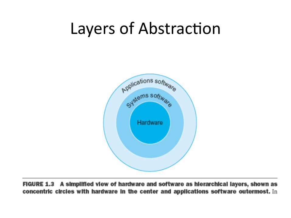
Layers of Abstraction
• Hardware in a computer can only execute extremely simpler low level instructions
• To go from complex applications to simple instructions involves several layers of software that interpret/ translate high level operations into simple computer instructions.

• These layers of software are organized in hierarchical fashion , with applications being the outermost ring and a variety of system software sitting between the hardware and application software.
Layers of Abstraction

System software: • It is a type of computer program that is
designed to run computer’s hardware and application programs.
• It provides a platform to other software.• It is the interface between hardware and use
applicationsEg: Operating Systems, Compilers , Assemblers

Operating System Supervising program that manages the
resources of a computer for the benefit of the programs that run on that machine.
Compiler A program that translates high level language
statements into assembly language statements.
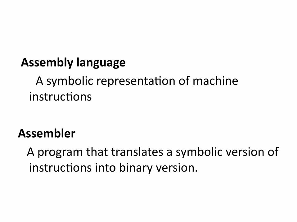
Assembly language A symbolic representation of machine
instructions
Assembler A program that translates a symbolic version of
instructions into binary version.


Five key components of a computer

Five key components of a computer
• INPUT• OUTPUT• MEMORY • DATAPATH• CONTROL

System Block Diagram
Chapter 7 CPU and Memory 7-23

DATAPATH
A data path (also written as datapath) is a set of functional units ,such as arithmetic logic units or multipliers that perform data processing operations, registers, and buses.
Functional units carry out data processing operations.
Datapath, along with a control unit, make up the CPU (central processing unit) of a computer system.

CPU • ALU (arithmetic logic unit)
– Performs calculations and comparisons (data changes)• CU (control unit): performs fetch/execute cycle
– Functions:• Moves data to and from CPU registers and other hardware components
(no change in data)• Accesses program instructions and issues commands to the ALU
– Subparts:• Memory management unit: supervises fetching instructions and data• I/O Interface: sometimes combined with memory management unit as
Bust Interface Unit • Registers
– Example: Program counter (PC) or instruction pointer determines next instruction for execution
Chapter 7 CPU and Memory 7-25

Arithmetic/Logic Unit • actual computation (the manipulation of data to generate
“new” data) takes place in the ALU. • Because data is represented in binary form (1’s and 0’s), the
ALU is mainly comprised of logic gates, circuits made from transistors that take inputs (combinations of highs and lows) and produce outputs (different combinations of highs and lows).
• Logic in which the output depends solely on the input is called combinatorial.
CSIT 301 (Blum) 26

The Little Man Computer
Chapter 7 CPU and Memory 7-27

Concept of Registers
• Small, permanent storage locations within the CPU used for a particular purpose
• Manipulated directly by the Control Unit• Wired for specific function• Size in bits or bytes (not MB like memory) • Can hold data, an address or an instruction
Chapter 7 CPU and Memory 7-28

Registers• Use of Registers
– Scratchpad for currently executing program• Holds data needed quickly or frequently
– Stores information about status of CPU and currently executing program• Address of next program instruction• Signals from external devices
• General Purpose Registers– User-visible registers– Hold intermediate results or data values, e.g., loop counters– Typically several dozen in current CPUs
Chapter 7 CPU and Memory 7-29

Special-Purpose Registers• Program Count Register (PC)– Also called instruction pointer
• Instruction Register (IR)– Stores instruction fetched from memory
• Memory Address Register (MAR)• Memory Data Register (MDR) • Status Registers– Status of CPU and currently executing program– Flags (one bit Boolean variable) to track condition like
arithmetic carry and overflow, power failure, internal computer error
Chapter 7 CPU and Memory 7-30

Register Operations
• Stores values from other locations (registers and memory)
• Addition and subtraction• Shift or rotate data• Test contents for conditions such as zero or
positive
Chapter 7 CPU and Memory 7-31

Control Unit
• Control is responsible for determining what action is to be performed on what data.
• If the action is a calculation, then control will deliver the necessary data to the ALU, inform the ALU what particular action is to be performed, and then directs the output to the appropriate location.
CSIT 301 (Blum) 32

Control Cont.
• All of the other units of a computer have “control inputs” that determine whether or not they are active and what particular action they will perform (if they can do more than one thing).
• Control takes code down to this lowest level of making the appropriate control inputs high or low, active or inactive. – Not all devices are active when the control input is high,
some devices are “active low.”
CSIT 301 (Blum) 33

ROM - Read Only Memory• Non-volatile memory to hold software that is not
expected to change over the life of the system• Magnetic core memory• EEPROM – Electrically Erasable Programmable ROM– Slower and less flexible than Flash ROM
• Flash ROM – Faster than disks but more expensive– Uses
• BIOS: initial boot instructions and diagnostics• Digital cameras
Chapter 7 CPU and Memory 7-34

Control is ROM
• At a high level, instructions may be arranged in new and different orders (this after all is what makes the computer programmable). But at the low level the control sequences for a given instruction do not change.
• Control sequences are thus made of Read Only Memory (ROM) which are reprogrammed rarely if at all.
CSIT 301 (Blum) 35

Memory
• Memory consists of circuits whose primary purpose is to hold information, but only temporarily.
• Memory holds the data that the processor has just acted on, is acting on or will soon act on.
• When we use the term memory, we usually mean Random Access Memory (RAM).
CSIT 301 (Blum) 36

RAM: Random Access Memory
• DRAM (Dynamic RAM)– Most common, cheap– Volatile: must be refreshed (recharged with power) 1000’s
of times each second
• SRAM (static RAM)– Faster than DRAM and more expensive than DRAM– Volatile– Frequently small amount used in cache memory for high-
speed access used
Chapter 7 CPU and Memory 7-37

Random Access
• The data in any holding cell can be accessed immediately for purposes of reading or writing by supplying its address. – Any random site can be “immediately” accessed.– As opposed to sequential access in which one must pass
through all intermediate data between one’s current location and the next desired location. • VCR tapes are sequential; • DVDs are random access (they support scene selection and don’t have
to be rewound).
CSIT 301 (Blum) 38

Operation of Memory
• Each memory location has a unique address• Address from an instruction is copied to the MAR
which finds the location in memory• CPU determines if it is a store or retrieval• Transfer takes place between the MDR and memory
Chapter 7 CPU and Memory 7-39

Memory
CSIT 301 (Blum) 40
Address Value
0000 10010100
0001 01010010
0010 00101100
0011 01011100
0100 01100110
…
Memory is collection of holding cells (like registers). Each cell has an address.

Relationship between MAR, MDR and Memory
Chapter 7 CPU and Memory 7-41
Address Data

MAR-MDR Example
Chapter 7 CPU and Memory 7-42

Visual Analogy of Memory
Chapter 7 CPU and Memory 7-43