computationalfluiddynamics/monte
TRANSCRIPT

COMPUTATIONAL FLUID DYNAMICS /MONTE
CARLO SIMULATION OF DUSTY GAS FLOWIN A ¤ROTOR�STATOR¥ SET
OF AIRFOIL CASCADES
Yu.M. Tsirkunov and D.A. Romanyuk
Baltic State Technical UniversityDepartment of Plasma- and Gas Dynamics and Heat Engineering
1 Krasnoarmeiskaya 1st Str., St. Petersburg 190005, Russia
A dusty gas §ow through two, moving and immovable, cascades of airfoils(blades) is studied numerically. In the mathematical model of two-phasegas�particle §ow, the carrier gas is treated as a continuum and it is de-scribed by the Navier�Stokes equations (pseudo-DNS (direct numericalsimulation) approach) or the Reynolds averaged Navier�Stokes (RANS)equations (unsteady RANS approach) with the Menter k�ω shear stresstransport (SST) turbulence model. The governing equations in bothcases are solved by computational §uid dynamics (CFD) methods. Thedispersed phase is treated as a discrete set of solid particles, the behav-ior of which is described by the generalized kinetic Boltzmann equation.The e¨ects of gas�particle interaction, interparticle collisions, and par-ticle scattering in particle�blade collisions are taken into account. Thedirect simulation Monte Carlo (DSMC) method is used for computa-tional simulation of the dispersed phase §ow. The e¨ects of interparticlecollisions and particle scattering are discussed.
1 INTRODUCTION
Military aircraft can sometimes operate in dusty atmosphere. Civilian airplanescan §y into a cloud of volcanic ash. In all these cases, one deals with a gas�particle §ow inside engine ducts. Dispersed particles suspended in a high-speedinlet §ow, being more inertial than the carrier gas, can collide with blades of a fan,a compressor, and even a turbine of a turbofan (or turbojet) engine resultingin abrasive erosion and quick failure of blades. The erosive e¨ect from particlescan reduce the lifetime of blades and, hence, of the whole engine, up to a factor
Progress in Propulsion Physics 8 (2016) 427-444 DOI: 10.1051/eucass/201608427© Owned by the authors, published by EDP Sciences, 2016
This is an Open Access article distributed under the terms of the Creative Commons Attribution License 4.0, which permits unrestricted use, distribution, and reproduction in any medium, provided the original work is properly cited.
Article available at http://www.eucass-proceedings.eu or http://dx.doi.org/10.1051/eucass/201608427

PROGRESS IN PROPULSION PHYSICS
of 10. For this reason, the problem of dusty gas §ow inside aircraft engines hasbeen the focus of attention for at least 40 previous years.Blades of a fan and an inlet stage of a low-pressure compressor are extremely
subjected to damage by high-speed particles£ impacts. Modeling and simulationof dusty gas §ow through rotating rows of blades is a very complex problem.Strictly speaking, a time-dependent §ow is three-dimensional (3D). However,many key §ow features in the sequential rows of blades can be studied usinga two-dimensional (2D) §ow model in the plane, which represents a developedmean-circle cross section. Such an approach turned out to be very fruitful for§ow analysis in axial-§ow compressors and turbines and it is well known as the2D theory of cascade §ow (see, e. g., [1]). Stationary 2D §ow of dilute gas�particle mixture with regular motion of monosized particles through a turbinecascade was studied numerically in [2] with special emphasis on application of thefull Lagrangian method, which gives very high resolution of the particle concen-tration ¦eld even in the case when singular surfaces with in¦nite concentrationappear in the §ow. Such singularities are typical for the §ow model taken in [2].However, these singularities disappear if some random in nature e¨ects such asinterparticle collisions, particle scattering in particle�blade collisions, and par-ticle size distribution are taken into account. Unsteady dusty gas §ow througha ¤rotor�stator¥ cascade with taking account of particle size distribution andparticle scattering was studied in [3].It is quite evident that if the particle concentration in the §ow is vanish-
ingly low, the reverse e¨ect of particles on the carrier gas is negligible and colli-sions between particles play no role. Estimations obtained in [4] for a §ow withcoarse-grained dispersed particles over a blunt body show that the collisions be-tween incident and rebounded particles begin to play a noticeable role at a muchlower particle concentration in an undisturbed §ow (at particle volume fractionαp∞ ∼ 10−5) than the concentration at which the reverse e¨ect becomes impor-tant. Closer examination showed that the e¨ect of particles on a carrier gas §owis determined not only by the particle concentration, but also by the relative par-ticle inertia, which is characterized by the Stokes number. In the present study,the authors assume that αp∞ is low enough to neglect the reverse e¨ect, but theinterparticle collisions are taken into account. The main objective is to estimatethe role of collisions in the redistribution of the dispersed phase in the §ow.A kinetic model for description of a collisional ¤gas¥ of particles was proposed
in [5]. In this model, the dispersed phase is treated as a set of a large number ofparticles and its state is described by the one-particle distribution function, simi-larly to the theory of rare¦ed gas dynamics. The generalized Bolzmann equationderived in [5] takes account of the carrier gas action on particles and frictionaland noncompletely elastic collisions between particles. To computationally sim-ulate the behavior of the collisional ¤gas¥ of particles, the DSMC algorithm wasdeveloped in [6]. In the present work, it was adapted for numerical study of theparticle phase §ow through airfoil cascades.
428

GAS TURBINE PROPULSION
2 ARRANGEMENT OF CASCADES
AND SCHEMATIC OF THE FLOW
Consider a two-phase gas�particle §ow through a set of two cascades (Fig. 1).The ¦rst cascade moves at constant velocity Vr in the direction normal to theundisturbed §ow and the second cascade is ¦xed. Both cascades have the samepitch s (the distance between airfoils along the cascade). The airfoils of the¦rst cascade are set at angle β. For visualizing the particle-phase §ow in thecomputational simulation, a cloud of particles of ¦nite width h was considered.
Figure 1 Arrangement of cascades in an undisturbed §ow
Consider the two-phase §ow as one-way coupled. This means that the e¨ectof the dispersed phase on the carrier gas can be ignored. In this case, modelingof gas�particle §ow can be reduced to two sequential steps: modeling of thecarrier gas §ow without taking the dispersed phase into account and calculationof the particle£s motion in the predetermined gas §ow ¦eld. Although the gas§ow is 2D, the motion of each particle is considered as 3D because 3D e¨ects areimportant for the interparticle collisions and scattering of particles in particle�blade collisions.
3 MODELING OF THE CARRIER GAS FLOW
Comparison of numerical results obtained for cascade §ow on the basis of inviscidand viscous gas §ow models clearly demonstrated that the viscous e¨ects play animportant role [3]. The §ow through cascades is usually turbulent. In the presentstudy of the §ow through a ¤rotor�stator¥ set of cascades, two §ow modelswere used to simulate the §ow ¦eld: (i) one based on complete Navier�Stokes
429

PROGRESS IN PROPULSION PHYSICS
equations (that corresponds to the pseudo-DNS approach, because the §ow wasconsidered as 2D, and the grid was too coarse for high resolution of turbulent §owstructure), and (ii) another based on the unsteady RANS equations (URANSapproach) with the Menter k�ω SST turbulence model [7, 8].The Navier�Stokes equations for time-dependent compressible 2D §ow can
be written in Cartesian coordinates (x, y) in the following compact form [9]:
∂Q
∂t+∂Fx
∂x+∂Fy
∂y=∂Gx
∂x+∂Gy
∂y(1)
where vectors Q, Fx, Fy, Gx, and Gy are de¦ned as follows:
Q =
ρρuρvρe
; Fx =
ρuρu2 + pρuv
(ρe+ p)u
; Fy =
ρvρuv
ρv2 + p(ρe+ p)v
;
Gx =
0τxx
τxy
uτxx + vτxy − qx
; Gy =
0τxy
τyy
uτxy + vτyy − qy
.
(2)
Here,
τxx =2
3µ
(2∂u
∂x− ∂v
∂y
); τyy =
2
3µ
(2∂v
∂y− ∂u
∂x
); τxy = µ
(∂u
∂y+∂v
∂x
); (3)
qx = −λ∂T∂x; qy = −λ∂T
∂y; p = ρRT ; e = cvT +
u2 + v2
2. (4)
In these equations, t is the time; u and v are the x- and y-components of thevelocity vector; ρ, p, e, T , µ, and λ are the gas density, pressure, speci¦c totalenergy, temperature, viscosity, and thermal conductivity, respectively; R is thegas constant; and cv is the speci¦c heat at constant volume. For µ and λ,the following relations were used: µ = µs(T/Ts)
3/2(Ts + Cs)/(T + Cs) and λ= cpµ/Pr where the ¦rst relation is the Sutherlend formula (for air, µs = 1.71 ·10−5 N·s/m2, Ts = 288 K, and Cs = 117 K); Pr is the Prandtl number; and cpis the speci¦c heat at constant pressure. The system of Eqs. (1)�(4) is closed.The full system of equations for the URANS approach with the Menter k�ω
SST turbulence model is very cumbersome [7, 8] and is not given here.
4 MODELING OF THE PARTICLE-PHASE MOTION
The motion of particles is governed by the gas�particle interaction, interparticlecollisions, and particle�blade collisions. The particles are more inertial than the
430

GAS TURBINE PROPULSION
carrier gas and, therefore, they do not follow the streamlines and can collide withblades and rebound (re§ect) from them. The re§ected particles can collide withthe incident ones; these collisions, being random in nature, result in chaotic mo-tion of particles. In the classical two-phase §ow theory, particles are assumed tohave a spherical shape; however, real particles (sand, ash, etc.) are not sphericaland because of this, they are scattered in particle�wall collisions. The particlescattering in cascade §ows was analyzed in [3] and it is taken into account in thepresent study.
4.1 Kinetic Model of the Collisional ¤Gas¥ of Particles
Here, the dispersed phase is considered as a discrete set of solid particles whichmove in the carrier gas and collide with each other. Below, the kinetic model forthe collisional ¤gas¥ of dispersed particles proposed in [5] is brie§y described. Itis assumed that particles are spheres of the same radius rp. They interact witheach other only through binary collisions that is valid if the ¤gas¥ of particles isnot too dense. Besides, it is assumed that collision process is instantaneous andthe position of colliding particles does not change during the collision. The stateof the ith particle is determined by a point xi in the phase space which includesthe particle position vector ri, the particle translational and rotational velocities(vpi and ωpi, respectively), i. e., xi = (ri,vpi,ωpi). The vector xi is split into riand yi = (vpi,ωpi). Denote the parameters of the ith and jth particles beforeand after their collision by the superscripts ¤minus¥ and ¤plus,¥ respectively.The postcollisional parameters of colliding particles are fully determined by theprecollisional ones and the relative position of particles at the collision instant;thus, one can write y+k = y
+k (y
−i ,y
−j ,nij), k = i, j, where nij is the unit
vector directed from the center of the ith particle towards the center of thejth particle at the collision instant. The above relation for y+k is presumedto give a one-to-one correspondence between y−k and y
+k , so that the Jacobian
J1 = |D(y+i ,y+j )/D(y−i ,y−j )| 6= 0 and, hence, the relation can be resolved forthe particle parameters before the collision y−k = y
−k (y
+i ,y
+j ,nij), k = i, j.
A collision is physically feasible only when g−ij ·nij ≤ 0 where gij = vj−vi. Also,assume that states of any two particles in the phase space are not statisticallycorrelated. This assumption is valid if the mean free path of particles movingin the carrier gas is much smaller than the particle momentum response length.These assumptions and reasoning are similar to those accepted in rare¦ed gasdynamics for collisions between molecules.Let f1 = f(x1, t) be the distribution function such that
f1 dx1 = f(r1,vp1,ωp1, t) dr1dvp1dωp1
is the number of particles with coordinates and velocities from the elementaryvolume dr1dvp1dωp1 in the vicinity of point x1 = (r1,vp1,ωp1) in the phase
431

PROGRESS IN PROPULSION PHYSICS
space. Then, the following kinetic Boltzmann-type equation for f1 can be de-rived:
∂f1∂t+
∂
∂r1(vp1f1) +
∂
∂vp1
(fp1mp
f1
)+
∂
∂ωp1
(Ip1Ipf1
)= Icoll . (5)
This equation is a particular case of the more general kinetic equation [5] whichalso takes gas�particle heat transfer and particle size distribution into account.The collisional integral in the right-hand side is given by
Icoll = 4r2p
∫dy2
∫
g12·n12≤0
(f−1 f
−2
J− f1f2
)|g12 · n12| sinχ12 dχ12dε12 (6)
where
J =
∣∣∣∣g12 · n12g−12 · n12
J1
∣∣∣∣ . (7)
Here, mp and Ip are the particle mass and moment of inertia; fp1 and Ip1 arethe force and the torque acting on a particle from the carrier gas which arecalculated for the particle with the parameters (vp1,ωp1) at point r1 in the §ow;f2 = f(r1,y2, t); f
−1 = f(r1,y
−1 , t); f
−2 = f(r1,y
−2 , t); g12 = vp2 − vp1; and n12
has been de¦ned above. The inequality g12 · n12 ≤ 0 is the condition of physicalfeasibility of a collision between the ¦rst and the second particles, and the anglesχ12 and ε12 specify the direction of n12 in spherical coordinates with the originat the center of the ¦rst particle [5].The function J which enters into the collisional integral is given by Eq. (7).
It depends on the particle�particle collision model which will be discussed later.Let � = �(xi) be a parameter of an individual particle. If a hydrodynamic
parameter of a ¤gas¥ of particles (in other words, macroparameter of the dis-persed phase) 〈�〉(r, t) at point r in the physical space is de¦ned as the ensembleaveraged value of � = �(xi) in a unit volume of the gas�particle mixture, then〈�〉(r, t) can be expressed in terms of � and f(x1, t) as follows:
〈�〉(r, t) =∫�(r,y1, t)f(r,y1, t) dy1 .
For example, the particle number density np, the particle volume fraction αp,the hydrodynamic velocity wp, and the speci¦c energy of particle chaotic motionep are calculated as follows:
np = 〈1〉 ; αp =4
3πr3pnp ; wp =
〈vp〉np; ep =
1
mpnp
⟨mp(vp −wp)
2
2
⟩.
The model of a noncompletely elastic collision between two particles is animportant part of the kinetic model of a collisional ¤gas¥ of solid particles. Write
432

GAS TURBINE PROPULSION
the momentum and angular momentum balance equations for a pair of the ithand the jth colliding spherical particles:
mpv−pi +mpv
−pj = mpv
+pi +mpv
+pj ;
Ip(ω+pk − ω−
pk) = mprpek ×(v+pk − v−pk
), k = i, j ,
(8)
where ei = nij , ej = −nij . The system of three-vector Eqs. (8) is not closedbecause it involves four unknowns v+pk and ω+pk, k = i, j. Some additionalhypotheses for the interaction between particles should be introduced to makethis system closed. Considering the relative velocity of particles at the contactpoint
Uij = vpj − vpi − rp(ωpi + ωpj)× nij , (9)
let us represent U+ij in the form
U+ij = −apnU−ij(n) + aptU
−ij(t) (10)
where apn and apt are the restitution coe©cients of the normal (Uij(n)
= (Uij · nij)nij) and tangential (Uij(t) = Uij − Uij(n)) components of therelative velocity Uij . These coe©cients are assumed to take into account thelosses of particle kinetic energy due to inelastic deformation during a collision(apn) and due to the particle surface roughness (apt). Their values lie in theranges: 0 ≤ apn ≤ 1 and −1 ≤ apt ≤ 1.The true values of apn and apt in di¨erent collision conditions are unknown,
and theoretical or experimental determination of them is very di©cult. Therestitution coe©cients have been assumed to be constant. If the values of apn
and apt are given, then the system of Eqs. (8)�(10) becomes closed and can besolved for the parameters of the ith and jth particles after their collision. In thiscase, one can also calculate the Jacobian
J1 =
∣∣∣∣∣D(y+i ,y
+j )
D(y−i ,y−j )
∣∣∣∣∣ = −apna2pt
and then the parameter J in the collisional integral of Eq. (7): J = a2pna2pt.
In reality, the absolute values of apn and apt are always less than unity; hence,J < 1. The multiplier 1/J in the collisional integral takes into account the¤compression¥ of the phase space caused by the losses of the kinetic energy ofcolliding particles. In calculations, the values of the restitution coe©cients weretaken as apn = 0.5 and apt = 0.9.If particles move in vacuum (i. e., fp1 = Ip1 = 0 in Eq. (5)) and collisions
between particles are completely elastic (i. e., apn = 1, apt = 1, and, hence,J = 1), then one comes to the model of a simple gas of molecules treated as hardspheres. In this case, Eq. (5) transforms to the well-known Boltzmann equationused in the rare¦ed gas dynamics.
433

PROGRESS IN PROPULSION PHYSICS
4.2 Gas�Particle Interaction
In the present study, the force fp acting on a particle included the drag force fDand the lift Magnus force fM (fp = fD + fM ) which dominate over all other forcecomponents in the §ow under consideration. These forces and the torque Ip canbe expressed in terms of the dimensionless coe©cients CD, Cω , and Cl:
fD =1
2CDπr
2pρ |v− vp| (v− vp) ;
fM =4
3Cωπr
3pρ [(ω − ωp)× (v− vp)] ;
Ip =1
2Clr
5pρ |ω − ωp| (ω − ωp)
where ω = (1/2)curlv. The coe©cients were calculated from the formulae ap-proximating the analytical, experimental, and numerical data in wide ranges ofthe governing parameters of the §ow around a single particle.The drag coe©cient CD was calculated from the approximation formula pro-
posed in [10] for subsonic §ow over a particle:
CD(Rep,Mp, Tp/T )
= 24
{Rep +
√γ
2Mp
[4.33 +
3.65− 1.53Tp/T
1 + 0.353Tp/Texp
(−0.247
√2
γ
RepMp
)]}−1
+
4.5 + 0.38
(0.03Rep + 0.48
√Rep
)
1 + 0.03Rep + 0.48√Rep
+ 0.1M2p + 0.2M8p
exp
(− Mp
2√Rep
)
+ 0.6
√γ
2Mp
[1− exp
(−Mp
Rep
)].
Here, Mp = |v− vp| /√γRT and Rep = 2ρ |v− vp| rp/µ are the particle Mach
and Reynolds numbers.In the §ow under consideration, the dependence of CD on Tp/T is very weak;
so, it was ignored and the ratio Tp/T was taken equal to unity.For calculation of Cω , the exact solution from [11] and the formula proposed
in [12] were used:
Cω =
3
4, 2γω < 0.45 ;
3
8�Cω , 2γω ≥ 0.45
where
γω =|ω − ωp| rp|v− vp|
;
434

GAS TURBINE PROPULSION
�Cω(γω,Rep) =0.45 + (2γω − 0.45) exp
(−0.075γ0.4ω Re
0.7p
)
γω.
The expression for the coe©cient Cl was Table 1 Coe©cients Cl1 and Cl2 indi¨erent ranges of the particle rota-tional Reynolds number Repω
Repω Cl1 Cl2
0�6 0 16π6�20 5.32 37.220�50 6.44 32.250�40 000 6.45 32.1
taken in the form proposed in [13]:
Cl =Cl1√Repω
+Cl2
Repω
where Repω = ρ |ω − ωp| r2p/µ, and con-stants Cl1 and Cl2 are given in Table 1.
4.3 Modeling of Particle�Blade Collisions
Two particle�blade collision models, deterministic and stochastic, were consid-ered in the present study. The ¦rst model was applied for spherical particles,and the second one for particles having the shape of a cube with cut vertices.In the last case, particles were assumed to have a random orientation relative tothe blade surface before a collision. The collision was taken to be nonsliding andonly partly elastic in both cases. In contrast to the case of a spherical particle,collision of a nonspherical particle with a blade is 3D. The present authors usedthe impact model described in detail in [14]. It is assumed that the impact in-teraction of a particle with a blade is instantaneous, and the particle position inspace during the impact is ¦xed.The equations of momentum and angular momentum for a particle have the
form:
mp
(v+p − v−p
)≡ mp△vp = S ; ‖Ip‖
(ω+p − ω−
p
)≡ ‖Ip‖ △ωp = rc × S . (11)
Here, S is the impact momentum acting on the particle at the contact point;‖Ip‖ is the tensor of inertia of the particle; rc is the position vector directedfrom the particle center of mass to the contact point (note that this vector isuniquely determined by particle orientation at the impact instant); and, as above,superscripts ¤−¥ and ¤+¥ denote the particle parameters before and after theimpact.Introduce the velocity vc of the particle contact point. This vector is deter-
mined by the kinematic relation
vc = vp + ωp × rc .
From this, one can obtain:
△vp ≡ v+c − v−c = v+p − v−p +△ωp × rc . (12)
435

PROGRESS IN PROPULSION PHYSICS
Combining Eqs. (11) and (12) yields
1
mp‖Ip‖△ωp = rc ×△vc − rc × [△ωp × rc] . (13)
Equation (13) contains two unknown vectors △vc and △ωp. Vector △vp canbe determined if the restitution coe©cients of the normal (anc) and tangential(aτc) to the surface components of vc de¦ned by
anc = −v+cn
v−cn
; aτc =v+cτ
v−cτ
are known. Actually, these coe©cients depend on the particle and surface mate-rials, particle shape, collision angle, and precollisional particle parameters. Forthe model of nonsliding collision, the coe©cient aτc is equal to zero. The co-e©cient anc is taken to be constant. In this case, Eq. (13) is the equation fora single unknown △ωp. The method of solving this equation is described in [14].The ¦nal relation for the velocity of the particle mass center after the collision is
v+p = v−p +△vc −△ωp × rc .
The equation for the postcollisional particle angular velocity is very cumbersome.The method of its solution is described in [14].At the blade surface (at r = rw), the boundary condition for the distribution
function f(r,y1, t) is determined by a particle�blade collision model. In generalcase, valid for deterministic and stochastic collision models, the distributionfunction must satisfy the relation [5]
|v1 · nw| f(r,y1, t) =∫
v−
1·nw<0
∣∣v−1 · nw
∣∣Ww
(y−1 → y1|nw
)f(rw,y
−1 , t)dy−1
where v1 · nw > o; Ww
(y−1 → y1|nw
)is the conditional distribution density
of particle parameters y1 after rebound from the surface at the given values ofparameters before the collision y−1 ; nw is the unit vector normal to the sur-face and directed from the blade to the §uid. The density Ww(y
−1 → y1|nw)
is to be calculated on the basis of the collision model. If the particle parame-ters are being changed deterministically during a collision, according to the lawy1 = y
+w(y
−1 ,nw), then Ww(y
−1 → y1|nw) = δ6(y1 − y+w(y1,nw)) where δ6 is
the 6-dimensional Dirac function. In the case of a stochastic collision model, thedensity Ww(y
−1 → y1|nw) may be determined by the direct statistical simula-
tion method based on calculations of a large number of collisions with randomparticle orientation prior to a collision. A similar technique was used in [14]for determination of scattering indicatrices of nonspherical particles reboundingfrom a smooth and a rough surface.
436
GAS TURBINE PROPULSION
5 NUMERICAL METHOD
As it was mentioned above, the two-phase gas�particle §ow is considered withouttaking into account the action of the particle phase on the carrier gas §ow. Twoquite di¨erent approaches were used for simulating of the gas §ow and the particlephase §ow.
5.1 Computational Fluid Dynamics Simulation of the Carrier GasFlow
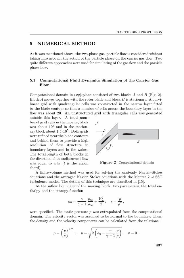
Computational domain in (xy)-plane consisted of two blocks A and B (Fig. 2).Block A moves together with the rotor blade and block B is stationary. A curvi-linear grid with quadrangular cells was constructed in the narrow layer ¦ttedto the blade contour so that a number of cells across the boundary layer in the§ow was about 20. An unstructured grid with triangular cells was generatedoutside this layer. A total num-
Figure 2 Computational domain
ber of grid cells in the moving blockwas about 105 and in the station-ary block about 1.5·105. Both gridswere re¦ned near the blade contoursand behind them to provide a highresolution of §ow structure inboundary layers and in the wakes.The total length of both blocks inthe direction of an undisturbed §owwas equal to 4.4 l (l is the airfoilchord).A ¦nite-volume method was used for solving the unsteady Navier�Stokes
equations and the averaged Navier�Stokes equations with the Menter k�ω SSTturbulence model. The details of this technique are described in [15].At the in§ow boundary of the moving block, two parameters, the total en-
thalpy and the entropy function
h0 =γ
γ − 1p∞ρ∞+V 2∞2; s =
p
ργ ,
were speci¦ed. The static pressure p was extrapolated from the computationaldomain. The velocity vector was assumed to be normal to the boundary. Then,the density and the velocity components can be calculated from the relations:
ρ =
(p
s
)1/γ
; u =
√2
(h0 −
γ
γ − 1p
ρ
); v = 0 .
437

PROGRESS IN PROPULSION PHYSICS
In the case of URANS approach with the use of Menter k�ω SST turbulencemodel, the turbulent kinetic energy k and ω were speci¦ed in addition:
k =3
2(V∞It)
2; ω =
ρk
µt.
In calculations, the turbulence intensity was taken It = 5% and the turbulentviscosity µt = (1 . . . 10)µ.At the out§ow boundary of the stationary block, the static pressure was
speci¦ed as pout = 1.2p∞ and all other parameters were extrapolated from thecomputational domain.Periodical in y-direction boundary conditions at the top and bottom bound-
aries of each block were applied. At the boundary between the blocks, a specialmatching procedure was used [15].
5.2 Monte Carlo Simulation of the Particle Phase Motion
Although the mathematical formulation of the problem for the particle phaseincludes the generalized Boltzmann equation (5) for the distribution function f1= f(r1,vp1,ωp1, t) with the collisional integral (6), the macroparameters〈�〉(r, t) of the dispersed phase, which are of principal interest, can be deter-mined by the DSMC method without solving the kinetic equation (5). In thiscase, simulation of the particle phase behavior includes two steps: (i) calculationof collisions between particles; and (ii) calculation of particle movement. Thereare several versions of this method. In the present study, the version describedin detail in [6] was used.Collisions and motion of particles were considered in 3D formulation within
a 3D layer 1 mm thick in z-direction normal to the (x, y)-plane. At the side(parallel to (x, y)-plane) boundaries of this layer, the periodic in z-directionconditions were used: if any particle left the layer through a side boundary, itwas excluded from consideration and a new particle with the same parameterswas introduced into calculations at the opposite side. The number density ofsimulated particles in the undisturbed particle cloud was taken equal to that ofreal dispersed particles. Simulated particles were uniformly distributed in spacein the undisturbed cloud.Calculations of particles£ motion were started up when the time-dependent
§ow of the carrier gas in the simulation reached a quasi-periodical regime. Thisdelay is equal to the time required for the rotor cascade to travel a distanceof about 30 pitches s (see Fig. 1). The shape of particles in particle�bladecollisions was taken either spherical or cubic with cut vertices; however, theparticles of both shapes were considered as spherical in gas�particle interactionand in interparticle collisions.
438
GAS TURBINE PROPULSION
6 COMPUTATIONAL RESULTS AND DISCUSSION
The parameters of the cascades and §ow properties in calculations were takenclose to those which are typical for an inlet compressor of a turbojet engine.The chord of airfoils was equal to l = 10 cm, cascade pitch s = 7 cm, angleβ = 45◦, the pro¦le of blades was NACA 0012, undisturbed §ow velocity V∞= 100 m/s, rotor cascade velocity Vr = 150 m/s, the carrier gas was air (R= 287 J/(kg·K) with the ratio of speci¦c heats cp/cv = 1.4); Prandtl numberPr = 0.72, and §ow density and temperature ρ∞ = 1.21 kg/m
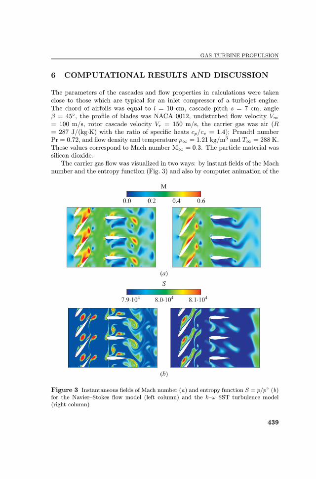
3 and T∞ = 288 K.These values correspond to Mach number M∞ = 0.3. The particle material wassilicon dioxide.The carrier gas §ow was visualized in two ways: by instant ¦elds of the Mach
number and the entropy function (Fig. 3) and also by computer animation of the
Figure 3 Instantaneous ¦elds of Mach number (a) and entropy function S = p/pγ (b)for the Navier�Stokes §ow model (left column) and the k�ω SST turbulence model(right column)
439

PROGRESS IN PROPULSION PHYSICS
motion of massless marking particles. The latter way allowed to trace gas motion,in particular, separation and formation of eddies. As is seen from Fig. 3, thecarrier gas §ow structure is rather complex. The results obtained for the Navier�Stokes §ow model and for the URANS §ow model are qualitatively similar toeach other. Large-scale eddies are formed and separated from blades. Notethat simulation on the basis of the Navier�Stokes model gives a more detailed§ow structure that is important for calculation of particles£ motion because theactual §ow parameters rather than the averaged ones determine the gas�particleinteraction and, hence, the particle behavior. Although the calculations wereperformed with the use of the Navier�Stokes equations and the URANS approachwith the Menter k�ω SST turbulence model, the results for particles are givenbelow only for the Navier�Stokes §ow model.In the strict sense, a time-periodic solution for the carrier gas §ow does not
exist. It is connected with two independent processes periodic in time, namely,separation of eddies from blades and motion of spatially periodic rotor bladesrelative to the stator blades with the same pitch. The ¦rst process is determinedby the Reynolds number of §ow around a blade, whereas the second one isdetermined by the velocity Vr and the cascade pitch s. If the periods of bothprocesses are not multiple, their interaction can result in ¤stochastic¥ behavior of§ow parameters with time. In computational simulation, a quasi-time-periodic§ow was obtained.The most impressive results are shown in Figs. 4�6. Patterns of a particle
cloud consisting of spherical and cubic particles are shown for various instants oftime in Figs. 4 and 5. Particles of sizes 20 µm and 40 µm correspond to Stokesnumbers Stk = 3.41 and 13.64, respectively. The Stokes number is de¦ned asthe ratio of the particle dynamic relaxation length (with the use of the Stokeslaw for a particle drag force) to the characteristic length in the §ow l: Stk= ρpd
2pV∞/(18µ∞l).
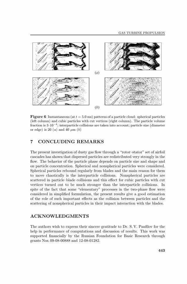
Spherical particles rebound from blades regularly, whereas cubic particlesre§ect stochastically. Scattering of cubic particles in their collisions with bladesa¨ects substantially the particle redistribution in the §ow. The e¨ect of collisionsbetween particles which also results in their chaotic motion and redistribution inspace, is much weaker even at rather high particle concentration. The value ofparticle volume fraction αp∞ = 3 ·10−4 in Fig. 6 corresponds to the particle massload on the order of unity in the undisturbed §ow. Figure 6 shows the e¨ect ofinterparticle collisions in forming the particle phase §ow structure. As is seenfrom comparing Figs. 6a and 6b with the snapshots at the bottom of Figs. 4and 5, respectively, the e¨ect of collisions is remarkable for spherical particleswhich do not scatter in particle�blade collisions, whereas for cubic particles,this e¨ect is negligible even at high particle concentration. This means thatin the latter case, the redistribution of cubic particles due to their scatteringin collisions with blades dominates substantially over the e¨ect of interparticlecollisions.
440

GAS TURBINE PROPULSION
Figure 4 Instantaneous patterns of a particle cloud: spherical particles (left column)and cubic particles with cut vertices (right column). Particle size (diameter or edge)is 20 µm. The particle volume fraction is 10−4; interparticle collisions are not takeninto account: (a) t = 0.5 ms; (b) 1.5; (c) 2.5; (d) 3.5; and (e) t = 5.0 ms
441

PROGRESS IN PROPULSION PHYSICS
Figure 5 Instantaneous patterns of a particle cloud: spherical particles (left column)and cubic particles with cut vertices (right column). Particle size (diameter or edge)is 40 µm. The particle volume fraction is 10−4; interparticle collisions are not takeninto account: (a) t = 0.5 ms; (b) 1.5; (c) 2.5; (d) 3.5; and (e) t = 5.0 ms
442
GAS TURBINE PROPULSION
Figure 6 Instantaneous (at t = 5.0 ms) patterns of a particle cloud: spherical particles(left column) and cubic particles with cut vertices (right column). The particle volumefraction is 3·10−4 ; interparticle collisions are taken into account; particle size (diameteror edge) is 20 (a) and 40 µm (b)
7 CONCLUDING REMARKS
The present investigation of dusty gas §ow through a ¤rotor�stator¥ set of airfoilcascades has shown that dispersed particles are redistributed very strongly in the§ow. The behavior of the particle phase depends on particle size and shape andon particle concentration. Spherical and nonspherical particles were considered.Spherical particles rebound regularly from blades and the main reason for themto move chaotically is the interparticle collisions. Nonspherical particles arescattered in particle�blade collisions and this e¨ect for cubic particles with cutvertices turned out to be much stronger than the interparticle collisions. Inspite of the fact that some ¤elementary¥ processes in the two-phase §ow wereconsidered in simpli¦ed formulation, the present results give a good estimationof the role of such important e¨ects as the collision between particles and thescattering of nonspherical particles in their impact interaction with the blades.
ACKNOWLEDGMENTS
The authors wish to express their sincere gratitude to Dr. S.V. Pan¦lov for thehelp in performance of computations and discussion of results. This work wassupported ¦nancially by the Russian Foundation for Basic Research throughgrants Nos. 09-08-00888 and 12-08-01282.
443
PROGRESS IN PROPULSION PHYSICS
REFERENCES
1. Stepanov, G.Yu. 1962. Hydrodynamics of cascades of turbomachines. Moscow:Fizmatlit. 512 p. (In Russian.)
2. Healy, D.P., and J. B. Young. 2005. Full Lagrangian methods for calculating parti-cle concentration ¦elds in dilute gas�particle §ows. Proc. R. Soc. A 461:2197�2225.
3. Tsirkunov, Yu.M., D.A. Romanyuk, and S.V. Pan¦lov. 2011. E¨ects of particlemixing and scattering in the dusty gas §ow through moving and stationary cascadesof airfoils. Progress in propulsion physics. Eds. L. DeLuca, C. Bonnal, O. Haidn,and S. Frolov. TORUS PRESS/EDP Sciences. 2:459�474.
4. Tsirkunov, Yu.M. 2001. Gas�particle §ows around bodies ¡ key problems, mod-eling and numerical analysis. 4th Conference (International) on Multiphase Flow(ICMF£2001) Proceedings. Ed. E. Michaelides. Paper No. 607. 31 p. CD-ROM.
5. Volkov, A.N., and Yu.M. Tsirkunov. 2000. Kinetic model of a collisional admix-ture in dusty gas and its application to calculating §ow past bodies. Fluid Dyn.35(3):380�392.
6. Volkov, A.N., and Yu.M. Tsirkunov. 2002. CFD/Monte Carlo simulation ofcollision-dominated gas�particle §ows over bodies. ASME FEDSM£2002 Proceed-ings. Paper No. 31222. 14 p.
7. Menter, F.R. 1994. Two-equation eddy-viscosity turbulence models for engineeringapplications. AIAA J. 32(8):1598�1605.
8. Menter, F., J. C. Ferreira, T. Esch, and B. Konno. 2003. The SST turbulence modelwith improved wall treatment for heat transfer predictions in gas turbines. GasTurnine Congress (International) Proceedings. Tokyo. Paper No. IGTC2003-TS-059. 7 p.
9. Tannehill, J. C., D.A. Anderson, and R.H. Pletcher. 1997. Computational §uidmechanics and heat transfer. 2nd ed. Taylor &Francis. 816 p.
10. Henderson, Ch.B. 1976. Drag coe©cients of spheres in continuum and rare¦ed§ows. AIAA J. 14(6):707�708.
11. Rubinow, S. I., and J. B. Keller. 1961. The transverse force on a spinning spheremoving in a viscous §uid. J. Fluid Mech. 11:447�459.
12. Oesterl‚e, B., and T. Bui Dinh. 1998. Experiments on the lift of a spinning spherein a range of intermediate Reynolds numbers. Exp. Fluids 25:16�22.
13. Dennis, S. C. R., S.N. Singh, and D.B. Ingham. 1980. The steady §ow due toa rotating sphere at low and moderate Reynolds numbers. J. Fluid Mech. 101:257�279.
14. Pan¦lov, S.V., and Yu.M. Tsirkunov. 2008. Scattering of nonspherical particlesrebounding from a smooth and a rough surface in a high-speed gas�particle §ow.J. Appl. Mech. Tech. Phys. 49(2):222�230.
15. Romanyuk, D.A., and Yu.M. Tsirkunov. 2010. Numerical simulation if unsteadydusty gas §ow through the moving and stationary cascades of airfoils. 5th Euro-pean Conference on Computational Fluid Dynamics: ECCOMAS CFD 2010 Pro-ceedings. Eds. J. C. F. Pereira and A. Sequeira. Paper No. 1063. 20 p. CD-ROM.
444