computational solid state chemistry 2 ssi-18 workshop 2011 rob jackson [email protected]
TRANSCRIPT
Computational Solid State Chemistry 2
SSI-18 Workshop 2011Rob Jackson

Contents and Plan
Modelling defects and dopants in ionic crystals
Calculation of energies of formation of defects in crystals
Modelling ion migrationDoping: substitution and solution energies
SSI-18 Workshop 3 July 2011 2
Defects: revision
• We are usually interested in studying the formation of:– Vacancies– Interstitials– Substitutional defects (e.g. Dopants)
• Point defects and defect clusters• Finite defect concentrations
SSI-18 Workshop 3 July 2011 3
Point defects and defect clusters
• The basis of the method used to calculate the formation energy of point defects and defect clusters is the Mott-Littleton Approximation.NF Mott, MJ Littleton, Trans. Faraday Soc., 1938,
34, 485A meeting was held in 1988 to mark 50 years
since the publication of the paper!Faraday Trans. II, 1989, 85, 335-579
SSI-18 Workshop 3 July 2011 4

N F Mott

6
Mott-Littleton approximation
Region IIons are strongly perturbed by the defect and are relaxed explicitly with respect to their Cartesian coordinates.
Region IIIons are weakly perturbed and therefore their displacements, with the associated energy of relaxation, can be approximated.Region IIa
Defect
Region I
© Mark Read (AWE)
SSI-18 Workshop 3 July 2011
Calculating the formation energy of defects in ionic crystals – (i)
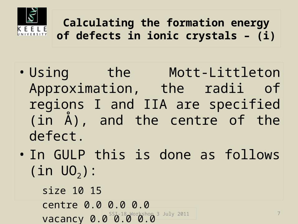
• Using the Mott-Littleton Approximation, the radii of regions I and IIA are specified (in Å), and the centre of the defect.
• In GULP this is done as follows (in UO2):size 10 15centre 0.0 0.0 0.0vacancy 0.0 0.0 0.0
• This will create a vacancy at the O site.
SSI-18 Workshop 3 July 2011 7

Calculating the formation energy of defects in ionic crystals – (ii)
• Running the GULP program with this information added to the basic dataset (from part 1), plus a few modifications to the initial keywords, will calculate the formation energy of an oxygen vacancy in UO2
• Defect clusters are treated in a similar way, except that the centre of the cluster can be specified.
SSI-18 Workshop 3 July 2011 8

GULP dataset for oxygen vacancy calculation in UO2
conp opti compare prop defe regi# UO2 Structure parameters obtained from:# Barrett, S.A.; Jacobson, A.J.; Tofield, B.C. and Fender, B.E.F.# Acta Crystallographica B (1982) 38, 2775-2781cell5.4682 5.4682 5.4682 90.0 90.0 90.0 fractional 4U core 0.00 0.00 0.00 -2.54U shel 0.00 0.00 0.00 6.54 O core 0.25 0.25 0.25 2.40 O shel 0.25 0.25 0.25 -4.40 space225# U-O potential from Read & Jackson , Journal of Nuclear Materials, 406 (2010) 293–303buckU shel O shel 1027.6 0.4026 0.0 0.0 15.0buck4O shel O shel 11272.6 0.1363 134.0 0.0 1.2 2.1 2.6 15.0springU core U shel 110.75O core O shel 296.2
vacancy 0.25 0.25 0.25size 10 15centre 0.25 0.25 0.25
SSI-18 Workshop 3 July 2011 9

Modelling ion migration – (i)
• For example, in solid electrolytes, ions can migrate via the vacancy mechanism, whereby an ion moves into a neighbouring vacant site, creating a vacancy which is then available for another ion to move into.
• This can be modelled by having two vacancies, with the migrating ion represented by an interstitial ion.
SSI-18 Workshop 3 July 2011 10
Modelling ion migration – (ii)
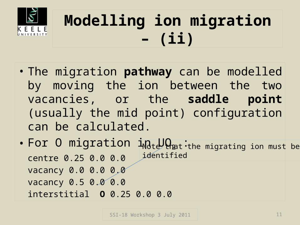
• The migration pathway can be modelled by moving the ion between the two vacancies, or the saddle point (usually the mid point) configuration can be calculated.
• For O migration in UO2 :centre 0.25 0.0 0.0vacancy 0.0 0.0 0.0vacancy 0.5 0.0 0.0interstitial O 0.25 0.0 0.0
SSI-18 Workshop 3 July 2011 11
Note that the migrating ion must beidentified
Calculating activation energies for ion migration
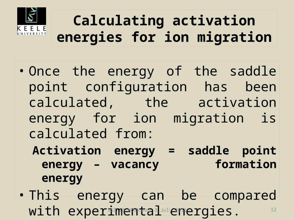
• Once the energy of the saddle point configuration has been calculated, the activation energy for ion migration is calculated from:Activation energy = saddle point energy – vacancy
formation energy• This energy can be compared with
experimental energies.
SSI-18 Workshop 3 July 2011 12

Dopants in crystals
• We may be interested in calculating the energy involved in substituting a different ion in a structure (where that ion adds functionality, e.g. in optical/sensor materials, or in YSZ (Y stabilised ZrO2))
• We will consider the process of substitution, and calculation of the substitution energy and the solution energy.
SSI-18 Workshop 3 July 2011 13

Introducing dopants – (i)
• To introduce dopants into the structure, the impurity keyword is used in GULP.
• In UO2, consider substituting a Pu (4+) ion at the U site:
centre 0.25 0.25 0.25impurity Pu 0.25 0.25 0.25
• In this case the charges are the same, so no charge compensation is needed.
SSI-18 Workshop 3 July 2011 14
Introducing dopants – (ii)
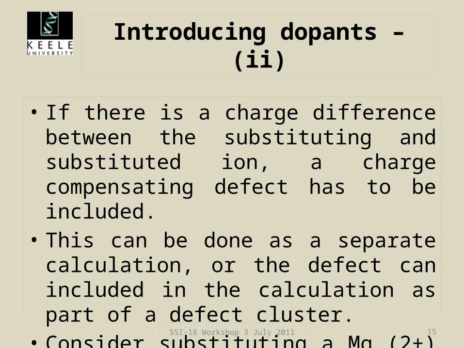
• If there is a charge difference between the substituting and substituted ion, a charge compensating defect has to be included.
• This can be done as a separate calculation, or the defect can included in the calculation as part of a defect cluster.
• Consider substituting a Mg (2+) ion into the UO2 structure (at the U site):
SSI-18 Workshop 3 July 2011 15

How charge compensation is included
• In this case we could calculate the substitution energy from:
centre 0.25 0.25 0.25impurity Mg core 0.25 0.25 0.25
• Charge compensation could be via a O2- vacancy; this energy could be calculated separately or included as an extra line:
vacancy 0.0 0.0 0.0
SSI-18 Workshop 3 July 2011 16

Substitution and solution energies
• Substitution energies do not give information about trends, since they do not take into account all the energetic terms involved in the solution process.
• We will consider the 2 cases already mentioned, and list all the energy terms involved.
Expressions for the solution energy (Esol) will be obtained.
SSI-18 Workshop 3 July 2011 17

(i) Pu in UO2
• Start with the oxide PuO2, and mix it with UO2.– Term 1: - Elatt (PuO2) (produces ions of Pu4+ and O2-)
– Term 2: substitution energy, Esubs (PuU) (from GULP)
– Term 3: Elatt (UO2) (the displaced U ion and the O combine)
• The solution equation is then:PuO2 + UU → PuU + UO2
Esol = - Elatt (PuO2) + Esubs (PuU) + Elatt (UO2)
SSI-18 Workshop 3 July 2011 18
(ii) Mg in UO2
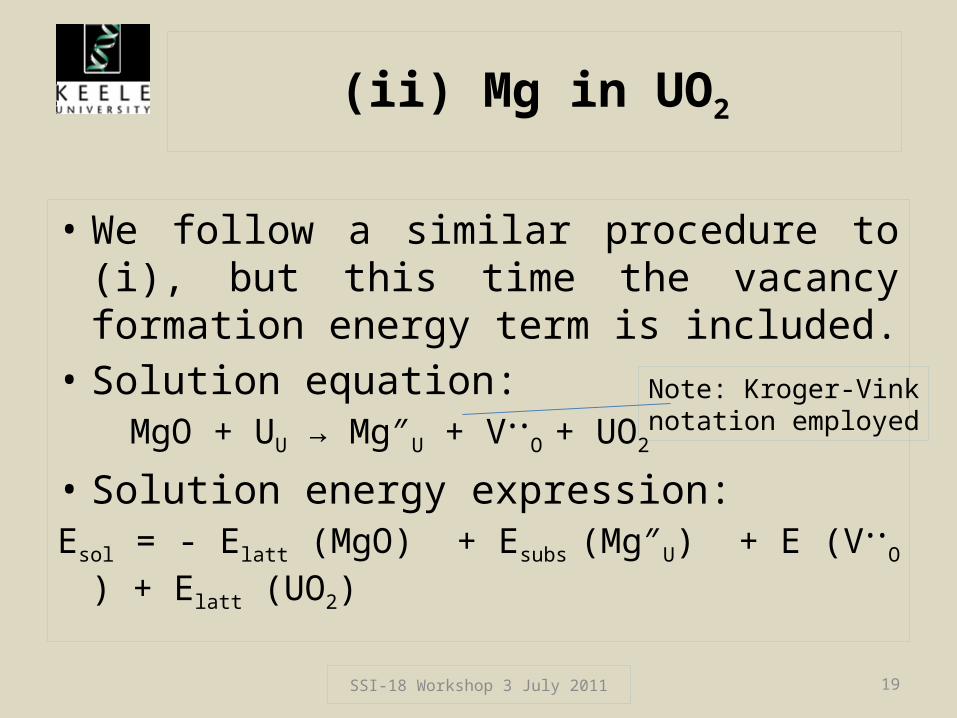
• We follow a similar procedure to (i), but this time the vacancy formation energy term is included.
• Solution equation:MgO + UU → Mg″U + V••
O + UO2
• Solution energy expression:Esol = - Elatt (MgO) + Esubs (Mg″U) + E (V••
O ) + Elatt (UO2)
SSI-18 Workshop 3 July 2011 19
Note: Kroger-Vinknotation employed

Bound and unbound defects
• In case (ii), the solution energy can be calculated using values of the substitution and vacancy formation energies calculated separately or together.
• In the second case, the defect binding energy is included in the calculation.
• Tables of bound and unbound solution energies can be found in papers.
SSI-18 Workshop 3 July 2011 20

Finite defect concentrations
• When considering doping, it is useful to be able to consider solution of more than one dopant ion in an infinite lattice (which is what has been presented so far).
• A new method has been developed which enables solution energies to be calculated as a function of dopant concentration.
• This will be presented in my talk tomorrow!
SSI-18 Workshop 3 July 2011 21

Conclusions for part 2
• Defects have been briefly revised.• The procedure for calculating point defect
formation energies has been explained.• The calculation of activation energies for ion
migration has been explained.• The calculation of substitution energies has
been explained, and solution energies introduced.
SSI-18 Workshop 3 July 2011 22