computational modelling of dynamic delamination in ... · morphing wings and blades have been...
TRANSCRIPT

393 Int. Jnl. of Multiphysics Volume 13 · Number 4 · 2019
Computational modelling of dynamic delamination in morphing composite blades
and wings
A S Fallah1,2*, M Ghajari2, Y Safa3 1. Brunel University London, London, United Kingdom 2. Imperial College London, London, United Kingdom 3. Zurich University of Applied Sciences, Winterthur,
Switzerland
ABSTRACT Morphing blades have been promising in lifting restrictions on rated capacity
of wind turbines and improving lift-to-drag ratio for aircraft wings at higher
operational angles of attack. The present study focuses on one aspect of
the response of morphing blades viz. dynamic delamination.
A numerical study of delamination in morphing composite blades is
conducted. Both components i.e. the composite part and the stiffener are
studied. The eXtended Finite Element Method (XFEM) and nonlocal
continuum mechanics (peridynamics) have both been used to study
fracture in the isotropic stiffener used in conjunction with the blade. As for
the composite morphing blade, cohesive elements are used to represent
the interlaminar weak zone and delamination has been studied under
dynamic pulse loads. Intraply damage is studied using the nonlocal model
as the peridynamic model is capable of addressing the problem adequately
for the necessary level of sophistication.
The differences and similarities between delamination patterns for
impulsive, dynamic, and quasi-static loadings are appreciated and in each
case detailed analyses of delamination patterns are presented. The
dependence of delamination pattern on loading regime is established,
however; further parametric studies are not included as they lie beyond the
scope of the study. Through the use of fracture energy alone the nonlocal
model is capable of capturing intra- and interlaminar fractures. The
proposed modelling scheme can thus have a major impact in design
applications where dynamic pulse and impact loads of all natures
(accidental, extreme, service, etc.) are to be considered and may therefore
be utilised in design of lightweight morphing blades and wings where
delamination failure mode is an issue.
1. INTRODUCTION As the level of functional requirements for an aircraft or turbine blade elevates so does the level of sophistication in design. One such scenario emerges when higher efficiency in energy production or higher pitch controllability to increase lift, minimise drag, and delay stall are desirable. To devise a conceptual design for a realistically functional blade one must consider
___________________________________ *Corresponding Author: [email protected]

394
Computational modelling of dynamic delamination in morphing
composite blades and wings
several requirements. Not only must the blade be aerodynamically efficient, among other things, but also structurally safe and operative. As such, the material for the blade must possess high strength-to-weight and stiffness-to-weight ratios but the design must also be flexible enough to render possible controllability thus a balance between competing goals must be reached. On the one hand, the structure must be robust and reliable under the application of possible loads, on the other hand, the shape of the blade must be aerodynamically optimised to maximise lift-to-drag ratio and avoid stall (thus loss of lift) at operative angles.
The primary structural requirements for the blade are its safety when subjected to service and ultimate loads during its lifetime as well as its fatigue durability [1-3]. To ensure structural robustness, optimal material and thickness distributions along the axis of the blade must be considered. Given the state of knowledge has grown in parallel with computational power, the designs of blades have changed throughout their development history [3,4].
Advances in structural aerodynamics have given rise to constant evolution in novel blade designs of improved airfoil cross sections and wings with continuous shape morphing. This allows these flexible structures to adapt continuously their shapes with respect to aerodynamic conditions and applied loads (see Fig.1). The smooth shape changes of the airfoil feature a strong potential to increase the lift capability and the aerodynamic stability (see Fig.’s 2 and 3). This morphing concept mimics the biologic systems in nature and currently attracts the attentions of researchers from both academia and industry. Hence, morphing airfoils have become a valuable candidate for innovative development in both aircraft and wind turbine technologies. Blades are nowadays designed employing either the active control concept (using solid state transducers, electro-active polymer, piezoelectric actuators) or passive control concepts. More specifically, some new wind turbines are considered with passive blades shape adaptation (without actuators, sensors, or any control devices). The simplicity of this passive pitching control system makes it a low-cost addition to the device and could dramatically increase the energy conversion of the rotor. As such, several recent works have been conducted on the aerodynamic characterization of such blades and experimental and computational studies galore have contributed to the field [3, 5-7]. However, the mechanical degradations associated with operations in designing the shape of morphing for the blade and structural limitations which arise have not been completely addressed.
Fig. 1: The schematic of a 2D airfoil cross-section with parameters shown and forces exerted depicted: F the total force, D the drag, L the lift, M the moment, c the chord length, α angle of attack, and 𝑉𝑉∞the distant wind speed
395 Int. Jnl. of Multiphysics Volume 13 · Number 4 · 2019
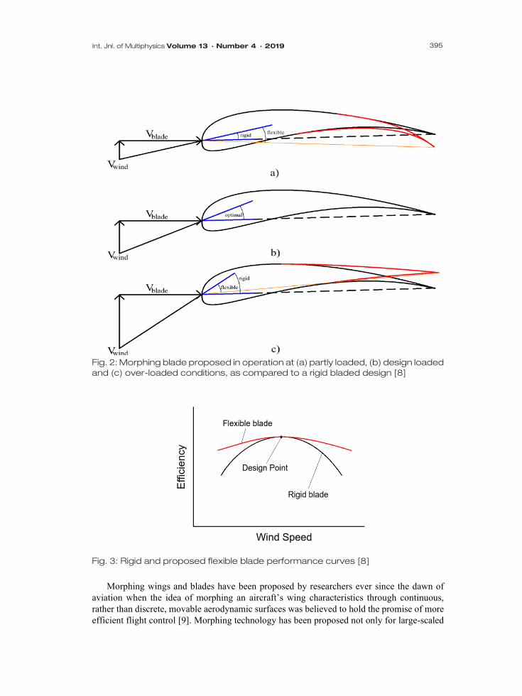
Fig. 2: Morphing blade proposed in operation at (a) partly loaded, (b) design loaded and (c) over-loaded conditions, as compared to a rigid bladed design [8]
Fig. 3: Rigid and proposed flexible blade performance curves [8]
Morphing wings and blades have been proposed by researchers ever since the dawn of
aviation when the idea of morphing an aircraft’s wing characteristics through continuous, rather than discrete, movable aerodynamic surfaces was believed to hold the promise of more efficient flight control [9]. Morphing technology has been proposed not only for large-scaled

396
Computational modelling of dynamic delamination in morphing
composite blades and wings
manned aircraft, but also for Unmanned Aerial Vehicles (UAV’s) where morphing combined with advances in actuator/sensor and material technology has given rise to a surge in interest in alternative morphing configurations capable of matching multiple mission profiles encountered sequentially in a single flight mission [10,11].
Composites have been proposed and used for the sake of aeroelastic tailoring [12]. As composites possess the potential to be stiffness-tailored several considerations must be made in their use. A multilevel approach accounting for aero-structure interaction might be needed to acquire an understanding of the actual spatial and temporal distribution of loading on the wing/blade. As such fluid-structure interaction (FSI) might be needed to be taken into account for accurate derivation of loading. This has been done by researchers [13]. These analyses, usually conducted using an arbitrary Eulerian-Lagrangian (AEL) finite element method, can quantify service and accidental extreme loads if enough information is provided. Such analyses have been done for metal and composite structures successfully [14,15].
While, more often than not, these blades and wings are subjected to service loads it may happen that ultimate loads of static or dynamic nature may be applied to them. As such, some or all modes of failure may be triggered. These include fibre failure, matrix cracking, in-plane shear failure, fibre micro-buckling, fibre-matrix debonding, and delamination. While most modes of failure occur within a ply of composite (intralaminar modes) delamination transpires in between plies and is thus referred to as interlaminar mode of failure. The resin rich layer (RRL) between adjacent plies where no fibres are present provides a weak link for delamination to initiate and propagate.
Delamination in composites due to dynamic loads has been widely studied [16-18]. One aspect of delamination in pulse-loaded laminated plates is attributed to ‘early time’ response i.e. spalling or scabbing failure modes, which transpire within micro-seconds, where the through-thickness compressive waves give rise to tensile stress waves on reflection from the free back face and result in mode I interlaminar failure [19-22]. Plate action which follows could lead to mode II and mixed-mode interlaminar fracture [23,24] similar to dynamic debonding of soffit plates in a strengthened beam [20].
Detailed analyses of such cases using numerical methods, such as the finite element method, and analytical models, as first- and higher-order shear deformation laminated plate theories [25,26], are possible and the theories can be used to study such cases. Analytical models may lead to closed-form solutions only for simple geometries, idealised material and loading conditions, and specific boundary conditions, and are thus limited. Furthermore, while initiation of cracking in the interlaminar zone is accurately predicted in these cases, crack propagation is a nonlinear problem and poses numerous new challenges which may only be adequately addressed within a numerical framework. Numerical modelling schemes as finite element method lead to a comprehensive framework for simulation of such cases as they allow for incremental solution of the nonlinear problem and lead to accurate results. Alternative powerful methods as nonlocal continuum mechanics-based model of peridynamics have also proven capable to capturing crack propagation, branching and coalescing accurately. The aim of the current study is thus to ensure a framework exists based on these methods which can address adequately all the major meso-scale and macro-scale phenomena as far as different modes of fracture are concerned. Modes I and II, and mixed mode fracture are included and the primary hypotheses of each model explained. Interlaminar and intralaminar fracture are considered and limitations discussed so the framework is capable of addressing the problem universally. The outline of this work is as follows.

397 Int. Jnl. of Multiphysics Volume 13 · Number 4 · 2019
In section 2 several analyses are conducted on both the stiffener and the morphing blade. Static analyses and frequency linear perturbation method are used to study the response for each case as well as to extract eigenvalues. Extended finite element method (XFEM) and nonlocal continuum mechanics model (peridynamics) are used to look into the maximum load carrying capacity of the stiffener and a linear perturbation eigenvalue solver is utilised to extract natural frequencies and modes. In section 3 dynamic delamination using cohesive traction-separation law and nonlocal continuum mechanics (peridynamics) have been used to study delamination in the composite morphing blade under pulse loading. Several regimes of loading are considered, however, intra-ply damage has not been included as (1) the focus has been on delamination and it is believed that this mode of damage precedes fibre failure, which is the detrimental mode of damage to a composite lamina and (2) enrichment functions (asymptotic crack tip functions) are not implemented for anisotropic media and the use of continuum damage mechanics requires implementation of a mesh-objective damage-mechanics based constitutive model which lies outside the scope of the present study. The intraply damage mode may be included using peridynamics as shown in this work. Section 4 concludes the studies conducted. 2. ANALYSES Airfoil cross sections in conjunction with twisted-pitch blades have been traditionally used as the preferred geometry in the design of wind turbine blades and aircraft wing structures. These forms have an aerodynamically advantageous performance as they generate a high ratio of lift to drag. Composite materials along with wood are used in the construction of blades as they possess superior strength-to-weight and stiffness-to-weight ratios. Glass fibre reinforced plastics (GFRP’s) also have very good fatigue resistance important to blade root design. As for flexible wings, carbon fibre reinforced plastics (CFRP’s) and aluminium are used as materials of preferred characteristics. As for geometries of the cross sections usually aerodynamically optimised sections are adopted from the libraries of NREL for wind turbine blades, and NACA for aircraft wings.
The stiffeners are usually sections without holes (see Fig. 4a) while the blade is made of a hollow section to allow morphing flexibility (see Fig. 4b). Both models, however, contain a hole to allow them be connected to the spar bar of the main wing structure.
As far as the global structural response is concerned both finite element simulations and analytical models may be used to acquire an understanding of static and dynamic behaviours of the blade. The level of complexity for analytical models depend on the desirable level of details to be derived accurately and economically which depends on what the intended use of analytical model is and the features it needs to represent faithfully. Simplified methods of analysis allow the derivation of some characteristic response parameter (e.g. displacement at a particular point) using a generalised parameter model such as an SDoF model [27] and/or more complicated models [28,29]. As an example the entire morphing blade or stiffener may be modelled as a non-prismatic beam semi-rigidly connected to a support as depicted schematically in Fig. 5a, a model which in itself may be viewed as the superposition of two models of Fig.’s 5b and 5c in static analysis or as a simplified generalised parameter SDoF model to be analysed dynamically.
Despite the fact that this model provides information on global response it does not provide the details of response at each section level nor does it allow for nonlinear damage phenomena as fracture, damage, or delamination.

398
Computational modelling of dynamic delamination in morphing
composite blades and wings
As far as aerodynamics is concerned, the lift increases as a function of the angle of attack
up to a limit, where loss of lift is encountered (see Fig. 6, which gives the dimensionless lift coefficient CL for a rigid airfoil as a function of the angle of attack). From the aerodynamics point of view the morphing blade is shaped in such a way that it can increase the angle of stall through flexible morphing thus to delay stall and provide lift for larger angles relative to air velocity, which is beneficial to energy production (for turbines) and flight mechanism (for aircraft).
(a)
(b)
Fig. 4: (a) the schematic of a homogeneous (e.g. aluminium) stiffener, (b)the schematic of a composite laminated morphing wing.

399 Int. Jnl. of Multiphysics Volume 13 · Number 4 · 2019
Flexible beamRotational spring
(a)
Rigid beamRotational spring
(b)
Flexible beam
Built-in support
(c)
Fig. 5: (a) Schematic of a non-uniform beam semi-rigidly connected to a pin support, (b) a rigid beam of the same cross section as (a) and semi-rigidly supported, (c) the flexible non-uniform beam rigidly connected to the support. (Note: superposition must be done as if these were springs in series i.e. Keq−1 = K1
−1 + K2−1 thus Ka
−1 = Kb−1 + Kc
−1).
Fig. 6: Schematic of non-dimensional lift (CL) as a function of angle of attack [30]. In the sequel, we shall present at first the results of static analyses on the stiffener, followed by analysis of failure using both extended finite element method (XFEM) [31-34] and peridynamics [35-38].

400
Computational modelling of dynamic delamination in morphing
composite blades and wings
2.1. Analysis of the stiffener 2.1.1. Static analysis As mentioned above, the stiffener is a non-prismatic beam with no holes connected to a spar bar which is sometimes controllable in length [9]. This section deals with static analysis of the stiffener, made of aluminium, and looks into the load vs deflection when subjected to uniform lower surface pressure load, replicating the operational pressure distribution. The effect of geometric nonlinearity is once excluded and once included in the model and the differences are discussed. In the latter case, the equations of equilibrium (and by extension, the equations of motion in the dynamic case) are derived based on the deformed configuration of the body undergoing deformation as a function of time. The type of aluminium selected is AA7050-T7451 with the properties as follows: Table 1: Material data for aluminium AA7050-T7451 [39] Property Value (unit) Density (ρ) 2800 (kg/m3) Young modulus(E) 72 (MPa) Poisson ratio (ν) 0.33 (-) Yield stress (σy) 469 (MPa) Ultimate tensile strength (σu) 524 (MPa) Fracture toughness (GIc) 11.14 (KJ/m2)
The finite element model has been set up assuming the geometry of the section is according
to NACA 8412 airfoil and the chord length is 100mm. A 3D geometry has been created in ABAQUS 2018, however, out-of-plane degrees of freedom are restrained as a plane strain condition is presumed and the hole is fully clamped as the effect of partial constrain of the spar bar has not been investigated. As such, this component (stiffener) is studied in isolation. As depicted in Fig. 7 a uniform lower surface pressure has been applied and the displacement at the trailing edge has been recorded. Fig. 8 shows the finite element discretisation of the stiffener. The out-of-plane thickness is taken as 4mm and there are 4 elements through the thickness.
Fig. 7: Geometry of the finite element model and loading distribution on the lower surface of the airfoil cross section
401 Int. Jnl. of Multiphysics Volume 13 · Number 4 · 2019
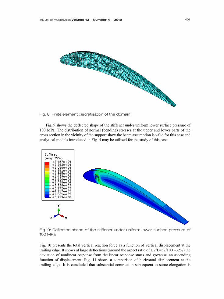
Fig. 8: Finite element discretisation of the domain
Fig. 9 shows the deflected shape of the stiffener under uniform lower surface pressure of
100 MPa. The distribution of normal (bending) stresses at the upper and lower parts of the cross section in the vicinity of the support show the beam assumption is valid for this case and analytical models introduced in Fig. 5 may be utilised for the study of this case.
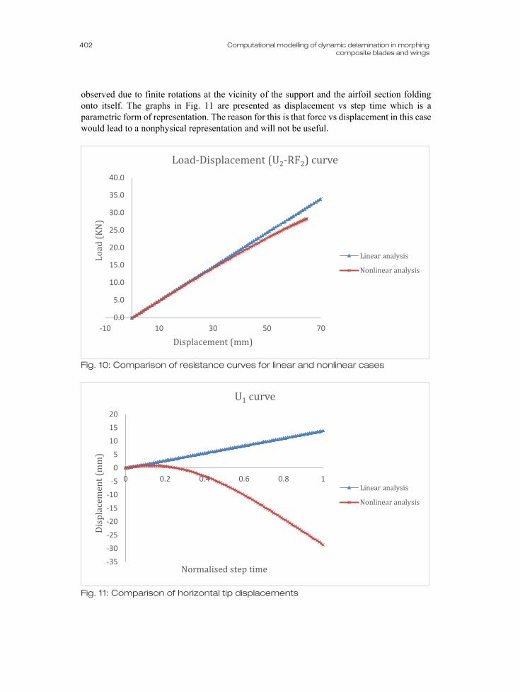
Fig. 9: Deflected shape of the stiffener under uniform lower surface pressure of 100 MPa Fig. 10 presents the total vertical reaction force as a function of vertical displacement at the trailing edge. It shows at large deflections (around the aspect ratio of U2/L=32/100 ~32%) the deviation of nonlinear response from the linear response starts and grows as an ascending function of displacement. Fig. 11 shows a comparison of horizontal displacement at the trailing edge. It is concluded that substantial contraction subsequent to some elongation is
402
Computational modelling of dynamic delamination in morphing
composite blades and wings
observed due to finite rotations at the vicinity of the support and the airfoil section folding onto itself. The graphs in Fig. 11 are presented as displacement vs step time which is a parametric form of representation. The reason for this is that force vs displacement in this case would lead to a nonphysical representation and will not be useful.
Fig. 10: Comparison of resistance curves for linear and nonlinear cases
Fig. 11: Comparison of horizontal tip displacements
0.0
5.0
10.0
15.0
20.0
25.0
30.0
35.0
40.0
-10 10 30 50 70
Load
(KN
)
Displacement (mm)
Load-Displacement (U2-RF2) curve
Linear analysis
Nonlinear analysis
-35
-30
-25
-20
-15
-10
-5
0
5
10
15
20
0 0.2 0.4 0.6 0.8 1
Disp
lace
men
t (m
m)
Normalised step time
U1 curve
Linear analysis
Nonlinear analysis

403 Int. Jnl. of Multiphysics Volume 13 · Number 4 · 2019
2.1.2. Frequency analysis
Along with the static analyses conducted, the eigenvalue problem has been solved to obtain the natural frequencies and natural modes of vibration. This is useful for two reasons: (1) it helps identify the regime of pulse loading as impulsive, dynamic, or quasi-static, as this depends on the ratio of loading duration to natural period of the first mode and (2) it may be used to solve for the dynamic response of linear systems using the method of mode-superposition which asserts the response can be obtained as a linear combination of natural modes.
Fig. 12: Base state (undeformed configuration)
Fig. 12 shows the base state or undeformed configuration of the stiffener. Once the
consistent finite element mass 𝑴𝑴 and stiffness 𝑲𝑲 matrices are derived based on the active degrees-of-freedom the eigenvalues may be obtained by solving the Eq. (1) as follows:
𝑑𝑑𝑑𝑑𝑑𝑑(𝑲𝑲 −𝜔𝜔2𝑴𝑴) = 0 (1)
The eigenvalues and eigenvectors may be obtained based on Lanczos or subspace
algorithms [40], and the latter has been used here. Fig.13 depicts the first four modes of vibration along with their associated frequencies.
The number of nodes and antinodes in each mode corresponds to the number of that mode and the wave number (inverse of wave length) decreases as the number of the mode (and its frequency) increases. It is expected that the dynamic response is a superposition of weighted modes, however, for dynamic pulses of long duration compared to the natural period of the first mode, most of the response occurs within the first few modes and the inclusion of all modes is not necessary.
Thus, more often than not, the regime of loading is determined by the ratio of pulse duration to the largest natural period i.e. the first mode’s natural period.

404
Computational modelling of dynamic delamination in morphing
composite blades and wings
Mode 1 vibration of the wing (f1=3026 Hz)
Mode 2 vibration of the wing (f2=10972 Hz)
Mode 3 vibration of the wing (f3=22280Hz)
Mode 4 vibration of the wing (f4=30544 Hz)
Fig. 13: The first four modes of vibration along with their associated frequencies 𝑓𝑓𝑖𝑖 = 𝜔𝜔𝑖𝑖/2𝜋𝜋 (both undeformed and deformed configurations are shown)

405 Int. Jnl. of Multiphysics Volume 13 · Number 4 · 2019
2.1.3. Analysis of failure using XFEM
Since fracture introduces a discontinuity into the displacement field and stress/strain field singularities at the crack tip, the analysis of fracture requires special techniques such as continuum damage mechanics (CDM), or extended finite element method (XFEM). Within the classical paradigm of fracture mechanics(such as linear elastic fracture mechanics (LEFM)) singularities are circumvented through the use of energy release rate (G-values or J-integral) or stress intensity factors (K-values) [41-43]. While CDM is based on weakening the failed zone based on the instantaneous amount of energy dissipated, XFEM is based on enrichment of the displacement function using asymptotic crack tip functions and the Heaviside step function[44]. XFEM has been used in the past successfully to study fracture initiation and propagation in isotropic and anisotropic media [31,34,45]. Eq. (2) shows the extrinsic enrichment of the displacement field using the Heaviside step function of Eq. (3a) and the asymptotic crack tip functions for an isotropic medium shown by Eq. (3b).
𝒖𝒖(𝒙𝒙) = ∑ 𝜓𝜓𝑖𝑖[𝒖𝒖𝑖𝑖 + 𝐻𝐻(𝒙𝒙)𝒂𝒂𝑖𝑖𝑁𝑁𝑖𝑖=1 + ∑ 𝒃𝒃𝑖𝑖𝑚𝑚4
𝑚𝑚=1 𝐹𝐹𝑚𝑚(𝒙𝒙)] (2)
Where 𝐻𝐻(𝒙𝒙) is the Heaviside function defined as follows:
𝐻𝐻(𝒙𝒙) = � 1 if (𝒙𝒙 − 𝒙𝒙∗).𝒏𝒏 ≥ 0 −1 otherwise
(3a)
Where 𝒙𝒙 is the location of a Gauss point and 𝒙𝒙∗ the point on the crack closest to 𝒙𝒙, and 𝒏𝒏
is the unit outward normal to the crack at 𝒙𝒙∗ and the asymptotic crack tip functions are as follows:
𝐹𝐹𝑚𝑚(𝒙𝒙) = �√𝑟𝑟 sin �𝜃𝜃2� ,√𝑟𝑟 cos �𝜃𝜃
2� ,√𝑟𝑟 sin(𝜃𝜃)sin �𝜃𝜃
2� ,√𝑟𝑟 sin(𝜃𝜃)cos �𝜃𝜃
2� � (3b)
As crack initiation is stress-based and propagation energy based, the stress at failure has
been used along with the G-value to replicate the cracking process (table 1). Under uniform pressure, the response entails the initial elastic response discussed in 2.1.1
followed by initiation and propagation of a discrete crack until ultimate failure as follows: The resistance curve (load-deflection) for uniform vertical traction is shown in Fig. 15.
The maximum load in this case is obtained as 527N which occurs when the tip displacement is 3.33mm.
On a closer examination, the progression of the cracking process and the associated stress distribution maybe analysed as follows:
At first stress concentration occurs around the square hole with maximum stress occurring at sharp corners. This is depicted in Fig. 16a. Then a crack forms and starts to propagate (Fig. 16b) until the two boundaries are hit by crack tips (Fig. 16c). At this point the structural integrity is lost and failure has occurred.
As level sets are used in XFEM, the contours of 𝜙𝜙 − and 𝜓𝜓 −levels are given in Fig.’s 17a and 17b. 𝜙𝜙 −level sets are defined to distinguish between the areas of enrichment above, along, or below the crack path while 𝜓𝜓-level sets are defined to discern between at, behind, or

406
Computational modelling of dynamic delamination in morphing
composite blades and wings
in front of the crack tip thus 𝜙𝜙 > 0 (𝜙𝜙 < 0) means above (below) the crack path and 𝜙𝜙 = 0 means along the crack path, while 𝜓𝜓 > 0 (𝜓𝜓 < 0) means in front of (behind) the crack tip and 𝜓𝜓 = 0 means at the crack tip.
Fig. 14: The pattern of cracking under uniform lower surface vertical traction
Fig. 15: Total load vs trailing edge vertical displacement
Evolution of cracking and relaxation of stresses near the cracked zone (shift in the position
of the maximum stress due to energy release and drop in stress levels in the vicinity of the crack tip and faces) is governed by energy release rate and is discussed in detail by researchers [46,47]. As reproducing elements contain a crack their status shifts from pristine to failed. Fig. 18 depicts the element status variable contour for reproducing elements.
0
0.2
0.4
0.6
0.8
1
1.2
0 1 2 3 4 5 6
Load
(KN
)
Displacement (mm)
Load-Displacement (U2-RF2) curve

407 Int. Jnl. of Multiphysics Volume 13 · Number 4 · 2019
(a)
(b)
(c)
Fig. 16. Von Mises Stress distribution/contour (a) prior to onset of cracking (areas of stress concentration around the hole are designated by the colour red), (b) propagation of cracking towards the boundaries, (c) loss of structural contiguity and strength

408
Computational modelling of dynamic delamination in morphing
composite blades and wings
(a)
(b)
Fig. 17. Level set functions (a) 𝜙𝜙 for enriched elements (b) 𝜓𝜓 for reproducing and blending elements
Fig. 18: XFEM status function (nonzero=failed, zero=pristine) for the reproducing elements through which crack evolves
409 Int. Jnl. of Multiphysics Volume 13 · Number 4 · 2019
2.1.4. Analysis of failure using peridynamics
An alternative method which allows for simulation of crack propagation and branching is peridynamics [35]. It is based on a reformulation of nonlocal continuum mechanics and allows for long-range interaction between continuum points. This method is used here to predict fracture patterns in aluminium and in a later section to look into fracture in composite blades and has also been extended to composite morphing blades. At the heart of the theory is inclusion of integrals in the equation of motion of elements, called particles here, which eliminates the need for a continuous displacement field as in the classical continuum mechanics theory [35, 48]. In a previous work, the bond-based peridynamic theory was extended to modelling fracture in anisotropic media by using spherical harmonics [49]. The details of the method may be found in the literature [35,50], and to avoid longevity and repetition here we will only state the fundamental equations.
The equation of motion in peridynamics reduces to an integral equation as follows:
𝜌𝜌(𝒙𝒙)�̈�𝒖(𝒙𝒙, 𝑑𝑑) = ∫ 𝒇𝒇(𝒖𝒖(𝒙𝒙′ 𝐻𝐻𝑥𝑥
, 𝑑𝑑) − 𝒖𝒖(𝒙𝒙, 𝑑𝑑),𝒙𝒙′ − 𝒙𝒙)𝑑𝑑𝑉𝑉𝒙𝒙′ + 𝒃𝒃(𝒙𝒙, 𝑑𝑑) (4)
Where ρ is the mass density in the reference configuration, 𝒖𝒖(𝒙𝒙, 𝑑𝑑) is the displacement
vector field, 𝒇𝒇 is a pairwise force function, which is of the dimension of the force per volume squared that the particle at position 𝒙𝒙 exerts on the particle at position 𝒙𝒙′, and 𝒃𝒃 is the body force vector field. While it is expected that the integral in Eq. (4) must be evaluated over the entire volume of the medium (𝛀𝛀𝟎𝟎) it is neither economic nor essential for this to be the case. As such, the concept of a horizon i.e. 𝐻𝐻𝑥𝑥 = {𝒙𝒙′ ∈ 𝛀𝛀𝟎𝟎 , |𝒙𝒙′ − 𝒙𝒙| < 𝛿𝛿} is introduced which signifies, as its radius (𝛿𝛿), the finite distance over which two particles can interact and the long-range forces are non-negligible. Defining as 𝝃𝝃 = 𝒙𝒙′ − 𝒙𝒙 the relative position of two points in the undeformed configuration and by 𝜼𝜼 = 𝒖𝒖(𝒙𝒙′, 𝑑𝑑) − 𝒖𝒖(𝒙𝒙, 𝑑𝑑) = 𝒖𝒖′ − 𝒖𝒖 the relative displacement of the two points at time ≥ 0 , the fundamental properties of the pairwise force function are as follows:
𝒇𝒇(𝜼𝜼, 𝝃𝝃) = 𝟎𝟎 ∀𝜼𝜼 , if ||𝝃𝝃|| > 𝛿𝛿 (5)
𝒇𝒇(−𝜼𝜼,−𝝃𝝃) = −𝒇𝒇(𝜼𝜼, 𝝃𝝃) ∀𝝃𝝃,𝜼𝜼 (6)
(𝜼𝜼 + 𝝃𝝃) × 𝒇𝒇(𝜼𝜼, 𝝃𝝃) = 𝟎𝟎 (7)
The deformation in a single bond is defined using the stretch parameter as follows:
𝑠𝑠 = ||𝜼𝜼+𝝃𝝃||−||𝝃𝝃||||𝝃𝝃||
= 𝜼𝜼.𝒏𝒏||𝝃𝝃||
(8)
Where 𝒏𝒏 = 𝝃𝝃+𝜼𝜼
||𝝃𝝃+𝜼𝜼|| and the constitutive equations for a bond is expressed by Eq. (9) and
critical stretch is related to the energy release rate as in Eq. (10):
𝑓𝑓(𝜼𝜼, 𝝃𝝃) = 𝑐𝑐𝑠𝑠(𝜼𝜼, 𝝃𝝃) (9)
410
Computational modelling of dynamic delamination in morphing
composite blades and wings
𝑠𝑠0 = �4𝜋𝜋𝐺𝐺09𝛿𝛿𝛿𝛿
(10)
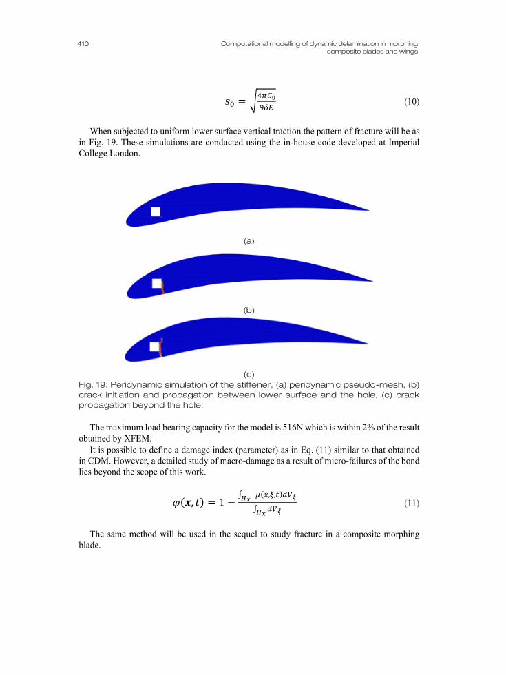
When subjected to uniform lower surface vertical traction the pattern of fracture will be as
in Fig. 19. These simulations are conducted using the in-house code developed at Imperial College London.
(a)
(b)
(c)
Fig. 19: Peridynamic simulation of the stiffener, (a) peridynamic pseudo-mesh, (b) crack initiation and propagation between lower surface and the hole, (c) crack propagation beyond the hole.
The maximum load bearing capacity for the model is 516N which is within 2% of the result
obtained by XFEM. It is possible to define a damage index (parameter) as in Eq. (11) similar to that obtained
in CDM. However, a detailed study of macro-damage as a result of micro-failures of the bond lies beyond the scope of this work.
𝜑𝜑(𝒙𝒙, 𝑑𝑑) = 1 −∫ 𝜇𝜇(𝒙𝒙,𝝃𝝃,𝑡𝑡)𝑑𝑑𝑉𝑉𝜉𝜉
𝐻𝐻𝑥𝑥
∫ 𝑑𝑑𝑉𝑉𝜉𝜉 𝐻𝐻𝑥𝑥
(11)
The same method will be used in the sequel to study fracture in a composite morphing
blade.

411 Int. Jnl. of Multiphysics Volume 13 · Number 4 · 2019
2.2. Analysis of the morphing blade The composite morphing blade forms the primary subject of this investigation since the idea of morphing is the core of sustainable flight mechanism or energy production for larger angles of attack. A single ply in a composite laminate comprises fibres and a matrix which may be arranged in several architectures e.g. unidirectional or woven. As such, the ply may be orthotropic or transversally isotropic and the plane of isotropy, in the latter case, depends on fibre architecture. A laminated plate’s constitutive matrix is therefore as in Eq. (12):
�𝑵𝑵𝑴𝑴� = �𝑨𝑨 𝑩𝑩𝑩𝑩 𝑫𝑫� �
𝜺𝜺𝒐𝒐𝜿𝜿 � (12)
It must be noted that at the material level the general form of a constitutive matrix for an
anisotropic material is 𝜎𝜎𝑖𝑖𝑖𝑖 = 𝐶𝐶𝑖𝑖𝑖𝑖𝑖𝑖𝑖𝑖𝜀𝜀𝑖𝑖𝑖𝑖. When this relation is integrated through the thickness of the laminated plate once for forces i.e. directly, and then when the moment equation i.e. stress times lever arm is integrated Eq.(12) is obtained.
As the geometry of the blade is complicated, numerical simulations are required to solve for the response under static and dynamic loads and we shall focus on the properties at ply level and will not directly use Eq.(12) to obtain the response. Furthermore, we will only consider unidirectional (UD) composites. Fig. 20 shows the schematic of possible direction of fibres in each ply (direction 1) and transverse direction (2) as well as through-thickness direction (3) for two consecutive plies of the composite laminate. For the sake of this study only carbon fibre reinforced plastic (CFRP=graphite-epoxy) has been considered, however, the method is general and can accommodate other types of FRP’s. Table 2 shows material properties used in the analyses. For the sake of comparison, some other composites are also included.
Normally fibre orientations vary through the thickness of a laminate to provide reasonable directional stiffness and strength. For instance, for aeronautical composites, material orientation of [0/45/-45/90] is a suitable one. However, in the present study as delamination is of interest and maximum interlaminar stresses are observed when maximum stiffness mismatch is achieved, i.e. maximum deviation in angles of adjacent plies is present, only the [0/90] architecture is considered. The methodology is nevertheless general and can accommodate any angle of orientation for fibres.
As for constitutive modelling of the RRL or cohesive layer damage initiation is stress-based but propagation is energy-based. In the simulation software program used (ABAQUS 2018) damage could be modelled using cohesive elements with continuum or direct traction-separation formulations. This approach is similar to discrete crack propagation due to equality of J-integral with critical energy release rate. As in the current study the RRL is assumed very thin the variation of stress through the thickness is ignored and the layer can be modelled using the direct traction-separation cohesive model. The following equations are related to damage initiation and propagation in the context of cohesive element modelling.
In the direct traction-separation formulation damage initiation is dictated by the following hyper-surface in the space of non-dimensional tractions:
�⟨𝑡𝑡𝑛𝑛⟩𝑡𝑡𝑛𝑛0�2
+ �𝑡𝑡𝑠𝑠𝑡𝑡𝑠𝑠0�2
+ �𝑡𝑡𝑡𝑡𝑡𝑡𝑡𝑡0�2
= 1 (13)

412
Computational modelling of dynamic delamination in morphing
composite blades and wings
Where ⟨𝑥𝑥⟩ is equal to 𝑥𝑥 if 𝑥𝑥 > 0 and zero otherwise. Crack propagation is governed by modal energy release rates as follows:
�𝐺𝐺𝑛𝑛𝐺𝐺𝑛𝑛𝐶𝐶�2
+ �𝐺𝐺𝑠𝑠𝐺𝐺𝑠𝑠𝐶𝐶�2
+ �𝐺𝐺𝑡𝑡𝐺𝐺𝑡𝑡𝐶𝐶�
2= 1 (14)
Where each numerator is obtained as the line integral of Eq. (15) geometrically depicted in
Fig. 21.
𝐺𝐺𝑖𝑖 = ∮ 𝜎𝜎𝑖𝑖 𝐶𝐶 𝑑𝑑𝛿𝛿𝑖𝑖 (15)
(a)
(b)
Fig. 20: Schematic of a composite morphing blade with direction of fibres (1) depicted for (a) the top ply, (b) the ply underneath

413 Int. Jnl. of Multiphysics Volume 13 · Number 4 · 2019
Table 2. Typical mechanical properties for some unidirectional lamina (data extracted from [51]). Property Glass-Epoxy
(MPa) Boron-Epoxy (MPa)
Graphite-Epoxy (MPa)
Kevlar®-Epoxy (MPa)
E1 5.4E4 2.07E5 2.07E5 7.6E4 E2 1.8E4 2.1E4 5E3 5.5E3 υ12 .25 .3 .25 .34 G12 9E3 7E3 2.6E3 2.1E3 G23 2.5E3 1.5E3 0.6E3 0.8E3
Fig 21. Schematic of stress-displacement curve for the cohesive zone (the blue zone is the work expended in a loading-unloading cycle)
Since more often than not, failure occurs in a combination of modes the point on the hyper-
surface must be adjusted (see Fig. 22).
Fig 22. Mixed mode traction-separation degradation rules [52]
414
Computational modelling of dynamic delamination in morphing
composite blades and wings
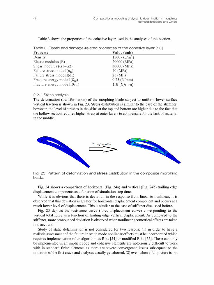
Table 3 shows the properties of the cohesive layer used in the analyses of this section.
Table 3: Elastic and damage-related properties of the cohesive layer [53] Property Value (unit) Density 1500 (kg/m3) Elastic modulus (E) 20000 (MPa) Shear modulus (G1=G2) 30000 (MPa) Failure stress mode I(σn) 40 (MPa) Failure stress mode II(σs) 25 (MPa) Fracture energy mode I(GIc) 0.25 (N/mm) Fracture energy mode II(GIc) 1.5 (N/mm)
2.2.1. Static analysis The deformation (transformation) of the morphing blade subject to uniform lower surface vertical traction is shown in Fig. 23. Stress distribution is similar to the case of the stiffener, however, the level of stresses in the skins at the top and bottom are higher due to the fact that the hollow section requires higher stress at outer layers to compensate for the lack of material in the middle.
Fig. 23: Pattern of deformation and stress distribution in the composite morphing blade.
Fig. 24 shows a comparison of horizontal (Fig. 24a) and vertical (Fig. 24b) trailing edge displacement components as a function of simulation step time.
While it is obvious that there is deviation in the response from linear to nonlinear, it is observed that this deviation is greater for horizontal displacement component and occurs at a much lower level of displacement. This is similar to the case of stiffener discussed before.
Fig. 25 depicts the resistance curve (force-displacement curve) corresponding to the vertical total force as a function of trailing edge vertical displacement. As compared to the stiffener, more pronounced deviation is observed when nonlinear geometrical effects are taken into account.
Study of static delamination is not considered for two reasons: (1) in order to have a realistic assessment of the failure in static mode nonlinear effects must be incorporated which requires implementation of an algorithm as Riks [54] or modified Riks [55]. These can only be implemented in an implicit code and cohesive elements are notoriously difficult to work with in standard finite elements as there are severe convergence issues subsequent to the initiation of the first crack and analyses usually get aborted, (2) even when a full picture is not

415 Int. Jnl. of Multiphysics Volume 13 · Number 4 · 2019
required and the effect of geometric nonlinearity could be implemented intrinsically a quasi-static explicit analysis would be required. This analysis will take a long time to run and does not provide much information as it does not lead to the correct resistance curve to be used in a subsequent dynamic analysis [27]. It is furthermore not an integral part of a dynamic analysis thus lies outside of the scope of the present work.
(a)
(b)
Fig. 24: Comparison of horizontal (a) and vertical (b) trailing edge displacement components as a function of step time
-10
-8
-6
-4
-2
0
2
4
0 0.05 0.1 0.15 0.2 0.25
Disp
lace
men
t (m
m)
Step time
Comparison of U1
Linear response
Nonlinear response
05
101520253035404550
0 0.05 0.1 0.15 0.2 0.25
Disp
lace
men
t (m
m)
Step time
Comparison of U2
Linear response
Nonlinear response

416
Computational modelling of dynamic delamination in morphing
composite blades and wings
Fig. 25: Comparison of resistance curves for linear and geometrically nonlinear cases
2.2.2. Frequency analysis Similar to the case of the stiffener a frequency analysis has been conducted to obtain the natural frequency of the first mode thus to determine the regime of response under pulse loading. As dynamic delamination is triggered based on the distribution of stresses which is, in its own right, dictated by the pattern of deformation in the blade, inclusion of higher modes (e.g. for impulsive case) gives rise to higher localised stresses where low stresses are normally encountered if only the first mode were to be considered (e.g. for quasi-static case). It is therefore helpful to acquire an insight into the regime of loading a priori so that we can expect different damage localisation modes.
Fig. 26 shows the first two modes of the vibration for the morphing blade. The associated frequencies are f1=542 Hz (T1=1/f1=0.002sec) and f2=2516 Hz (T2=1/f2=0.0004sec). Similar discussion as for the stiffener in terms of nodes, antinodes, wave number, etc. holds here and in the interest of brevity this line of explanation is not repeated.
0
100
200
300
400
500
600
700
800
900
1000
0 10 20 30 40
Reac
tion
forc
e (N
)
Displacement's vertical component U2 (mm)
Force-Displacement
Linear response
Nonlinear response

417 Int. Jnl. of Multiphysics Volume 13 · Number 4 · 2019
(a)
(b)
Fig. 26: The first two modes of vibration of the morphing blade

418
Computational modelling of dynamic delamination in morphing
composite blades and wings
3. DELAMINATION IN MORPHING BLADE Delamination in composite laminates has been the subject of extensive research both at structural and material levels with focus on inter-laminar shear and peeling stresses [16-18, 23,24,56]. Furthermore, dynamic crack propagation has been studied using 2D models (e.g. see [56]). However, the study of interfacial crack evolution in response to stress waves in a laminated structure is still a topic of active investigation form both modelling and experimental perspectives. Our aim here has been to develop a computational framework of predictive capability for the delamination under stress wave propagation. Dynamic fracture analyses are conducted using the cohesive layer model as the RRL.
Initially a single layer of cohesive was inserted to observe the possibility of static delamination. As mentioned before, it is possible, although time consuming and problematic, to attain results for static delamination. The result of static analysis conducted was reassuring as delamination in mode 2 was observed at the expected location. Fig. 27 shows the evolution of damage in the single cohesive layer inserted in the morphing blade. The concentration of shear stress at the edge gives rise to delamination as the damage parameter SDEG approaches 1 (SDEG=0 means intact and SDEG=1 means damaged or failed).
There will be relaxation of stress at the vicinity of this zone subsequent to failure and release of energy. Normal and shear interlaminar tractions alter based on the extent of damage and are calculated based on the damaged constitutive relations.
Fig. 27: Evolution of damage at the zone of high stress (Degradation of stiffness in the cohesive zone is shown using the contour of damage parameter SDEG with red elements signifying the failed/incipiently failed elements and blue elements denoting the intact ones)
3.1. Analysis of dynamic delamination using cohesive elements As an initial remark, it must be mentioned that the actual spatial and temporal distributions of pulse loading are complicated and cannot be reduced to simple analytic functions. Even in the static case the pressure and shear tractions at a particular angle of attack can have the form represented schematically by Fig. 28.
The morphing blade has been decomposed layer-wise and at distances 10mm apart cohesive elements are introduced. This means roughly every 20 plies are fully tied and delamination is only allowed through these weak zones which is a rational choice as in any economic model one has to sacrifice a bit of accuracy for the sake of economy.

419 Int. Jnl. of Multiphysics Volume 13 · Number 4 · 2019
Fig. 28: Schematic of pressure and shear distributions and their collective effect (Drag (D) and Lift (L)) [30]
To start, a pulse load of high intensity but short duration has been applied to the lower
surface. The spatial distribution is uniform and the pulse temporal shape is rectangular of duration 0.1 msec. The amplitude of the shock has been 5MPa to allow damage to be experienced by the blade. Fig. 29 show the evolution of damage in the blade.
Different stages of deformation have been explained in figure captions. As it is observed for the impulse imparted by this shock loading the damage is excessive and severe. It is expected that the blade loses its entire functionality due to this scenario of loading.
Along the same line a pulse load of uniform vertical traction distribution of intensity 2MPa and duration 0.1 msec was applied to the lower surface. The temporal shape of the pulse was an isosceles triangle. Fig. 30 shows the excessive shear deformation of elements on the top of the adhesive layer adjacent to the hole as a geometric discontinuity under impulsive triangular loading. It is expected that delamination should start here, however, due to low amplitude of the loading no deamination occurs in this case.
Subsequently, a triangular pulse load of amplitude 2 MPa and duration of 2 msec was applied and delamination instigated at the expected position and the interlaminar crack propagated until total detachment of one of the arms and loss of functionality of the entire blade. Fig. 31 shows the different stages of deformation.
As mentioned before, due to maximum elastic mismatch between the adjacent layers ([0/90] fibre alignment architecture) delamination is more likely in this case when compared to other fibre arrangements. Fig. 36 shows the distribution of stress in the case of an impulsive load of amplitude 0.5 MPa and duration of 0.1 msec. The sharp change in stress from one ply to the next is obvious.
Finally, a quasi-static triangular load of amplitude 2MPa and duration of 20msec is applied. General failure pattern in this case is similar to the dynamic case, however, since the loading duration is higher and the load is more gradually applied there is chance for formation of multiple cracks as observed in Fig. 33.

420
Computational modelling of dynamic delamination in morphing
composite blades and wings
(a). Initiation of delamination in the vicinity of the tail (t= 0.075 msec)
(b). Further delamination on the upper arm and initiation of delamination near the
hole (t= 0.09 msec)
(c). Further delamination on the lower arm and above the hole (t=0.12 msec)
(d). Complete detachment of lower and upper arms and substantial delamination
throughout the model
Fig. 29: Different stages of deformation in a shock loaded morphing blade (the load has been applied as underneath pressure)

421 Int. Jnl. of Multiphysics Volume 13 · Number 4 · 2019
Fig. 30: Excessive shear deformation of elements on the top of the adhesive layer adjacent to the hole under triangular impulsive loading. The hole functions as a geometric discontinuity. The contour of SDEG has been shown
(a) Delamination through shear failure at the top of the hole at t=0.45 msec
(b) Progression of failure and opening up of upper arm relative to lower arm
(t=0.55 msec)
(c) Complete detachment and failure of the wing through separation of lower
and upper arms (t=.58 msce) Fig. 31: Progression of damage under dynamic pulse loading

422
Computational modelling of dynamic delamination in morphing
composite blades and wings
Fig. 32: Distribution of stress (visible mismatch between laminae) in the blade under pulse load of p0=0.5 MPa and td=0.1 msec
(a) Propagation of cracking towards the outer free surface in the upper arm at
t=0.55 msec
(b) Total separation of upper arm at t=0.87 msec
(c) Onset of delamination from the edge of the lower arm at t=1.2 msec
(d) Delamination of the lower arm underneath the point of separation at t=1.6
msec Fig. 33: Progression of damage under quasi-static loading

423 Int. Jnl. of Multiphysics Volume 13 · Number 4 · 2019
3.2. Analysis of dynamic delamination using peridynamics Here peridynamics is used to simulate fracture patterns and loads in the morphing composite blades. In particular through inclusion of intra-laminar failure this approach is suitable to test whether there would be any interaction between inter- and trans-laminar fractures in the blades modelled.
It may be expected that the use of XFEM in conjunction with the cohesive model may yield the same results, however, XFEM has not been used as anisotropic asymptotic crack tip functions are not implemented in the software ABAQUS and separate coding is required to implement these effects. An XFEM code developed at Imperial College London could be used in theory, however, two associated issues do not allow for this: 1) the XFEM code must be substantially modified to allow for cohesive interaction and accurate propagation of cracking, and 2)the XFEM code must allow for complicated geometries such as the morphing blade to be accommodated. These capabilities are not developed yet.
In a previous work, the bond-based peridynamic theory was extended to modeling fracture in anisotropic media by using spherical harmonics [49]. Here we used this method to simulate inter and translaminar fracture in the composite morphing blades. For the sake of comparison and since the capabilities allow the composite stiffener, has also been included as an alternative to the aluminium stiffener. For the aluminum stiffener, the isotropic formulation of the theory was used. The material properties used for the simulations were elastic modulus, density and fracture toughness as presented in Table 1. For the composite layers, elastic modulus and fracture toughness in fibre and matrix directions were used. To model interlaminar fracture, the average of the stiffness constants in fibre and matrix directions and a translaminar fracture toughness was used. Material properties are shown in Table 3 plus the intarply fracture energies assumed as G1=31.9 and G2=2.2 N/mm [53] which refer to G-values in the fibre and transverse directions, respectively and not to modes I (normal) and II (shear) fracture.
We used an explicit solver the details of which could be found in [49]. The stable time increment that we used was approximately 14ns. Simulations were performed on an Intel Xenon (3.5GHz) CPU using 16GM RAM. The simulation wall-time for 0.2ms duration of the simulations was approximately 3 hours and 45 minutes and linearly increased with loading duration. Fig. 34 shows the three models set up using the in-house developed peridynamic solver software for the different materials considered.
Fig.’s 35 and 36 shows crack initiation and growth in the composite stiffener and morphing blade. The forces corresponding to the moment of crack initiation were 306 N and 191N, for the composite stiffener and the morphing blade, respectively.
In the composite blade (Fig. 35), the crack initiated between the composite layers (delamination) and continued as a delamination until the load bearing strength of the structure was significantly reduced. In this phase no trans-laminar crack was observed. However final catastrophic failure involved both inter and trans-laminar fracture. The location of crack initiation was different in the composite blade. The crack initiate near the bottom edge of the blade in the morphing composite blade and grew horizontally between the layers (Fig. 36). The strength of the blade were different with the aluminum blade being the strongest and the morphing the weakest thus the most vulnerable as well as the most flexible.

424
Computational modelling of dynamic delamination in morphing
composite blades and wings
Fig. 34: Peridynamic pseudo-mesh for (A) the aluminium stiffener, (B) the composite stiffener, (C) the morphing blade.
Fig. 35: Peridynamic predictions of fracture pattern and for the composite stiffener (loading increases as we move from top to bottom)
Fig. 36: Peridynamic predictions of fracture pattern and for the morphing blade (loading increases as we move from top to bottom)
425 Int. Jnl. of Multiphysics Volume 13 · Number 4 · 2019
4. DISCUSSION AND CONCLUSIONS The current study deals with presenting a computational modelling scheme for the study of morphing composite blades and their stiffeners which are used in aeronautical as well as green energy industries as an economically advantageous method for pitch control and maximisation of lift-to-drag ratio and delaying stall. This leads to optimising energy production in wind turbines and minimisation of fuel consumption for aircraft.
Aluminium stiffener and composite morphing blade are studied. Both extended finite element method (XFEM) and nonlocal continuum mechanics (peridynamics) have been used to study fracture in the stiffener. As for the composite morphing blade, cohesive elements are used to represent the RRL and delamination has been studied under shock, impulse, and pulse loads. The reason XFEM cannot be used to do so is the fact that asymptotic crack tip functions change for anisotropic materials [57] and have not been implemented in the commercial software used (ABAQUS 2018).
While both cohesive elements and peridynamics have been successful in capturing the pattern of delamination under uniform pressure and/or uniform lower surface vertical traction, under pulse loading only the results for cohesive elements are presented. This is due to the fact that peridynamic simulations will take a very long time and were merely conducted to conclude the similarity between the final results. Furthermore, finite element simulations using ABAQUS 2018 are much more commonplace in academia and industry and may be replicated by people who have access to the software while the peridynamic code is an in-house developed code used by advanced users at Imperial College London.
The differences and similarities between delamination patterns for impulsive, dynamic, and quasi-static loadings are appreciated and in each case detailed analyses of delamination patterns are presented. It is anticipated that in the case of an impulse higher modes of vibration are triggered and the delamination occurs throughout the blade in several locations simultaneously or sequentially, however, for quasi-static loading the pattern of fracture is more as propagation from a single location till complete separation and subsequent cracks are mostly geometric i.e. due to large deformations and change of initial configuration. For dynamic pulse a mixture of both phenomena may be encountered depending on whether the pulse is closer to an impulse or to a quasi-static load.
While it is generally recognised that initiation of cracking is problematic the analyses are carried out to appreciate the degree and mode of damage in each case up to total failure, if this occurs. Parametric and sensitivity studies may be conducted to appreciate the degree and direction of influence of model parameters involved (such as lay-up architecture, type of material, or fibre orientation), nevertheless, these have not been included as they would elongate the paper needlessly and provide little further contribution to the main core objective.
As a remark, it must be mentioned at this point, that the actual spatial and temporal distributions of pulse loading are complicated and cannot be reduced to simple analytic functions. For instance, the static pressure load at a particular angle of attack can have the form represented schematically by Fig. 28. As for pulse loads a more realistic pattern of loading may require a fully coupled fluid-structure analysis, a subject which is outside the scope of the present work. Such studies usually involve a coupled arbitrary Largrangian- Eulerian formulation and a domain decomposition algorithm [13,58-60].

426
Computational modelling of dynamic delamination in morphing
composite blades and wings
In conclusion, it is shown the proposed scheme is capable of capturing all major features
of dynamic delamination in composite morphing blades through an accurate, coherent, and consistent computational modelling scheme. This has a major impact in design applications where dynamic pulse and impact loads of all natures (accidental, extreme, service, etc.) are to be considered in design and therefore the framework may be used in design of lightweight morphing blades and wings.
ACKNOWLEDGEMENTS This work was supported by the Swiss National Science Foundation under the ‘Scientific Exchanges’ program Grant No. IZSEZO_178097. REFERENCES [1] Quarton, D. C. "The evolution of wind turbine design analysis—a twenty year progress
review." Wind Energy: An International Journal for Progress and Applications in Wind Power Conversion Technology 1.S1 (1998): 5-24.
[2] Rubiella, Clemence, Cyrus A. Hessabi, and Arash Soleiman Fallah. "State of the art in fatigue modelling of composite wind turbine blades." International Journal of Fatigue 117 (2018): 230-245.
[3] Wlezien, R., et al. "The aircraft morphing program." 39th AIAA/ASME/ASCE/AHS/ASC Structures, Structural Dynamics, and Materials Conference and Exhibit. 1998.
[4] Weisshaar, Terrence A., and R. J. Ryan. "Control of aeroelastic instabilities through stiffness cross-coupling." Journal of Aircraft 23.2 (1986): 148-155.
[5] Jonkman, Jason, et al. "Definition of a 5-MW reference wind turbine for offshore system development." National Renewable Energy Laboratory, Golden, CO, Technical Report No. NREL/TP-500-38060 (2009).
[6] Baroudi, Jamal A., Venkata Dinavahi, and Andrew M. Knight. "A review of power converter topologies for wind generators." Renewable energy 32.14 (2007): 2369-2385.
[7] Herbert, GM Joselin, et al. "A review of wind energy technologies." Renewable and sustainable energy Reviews11.6 (2007): 1117-1145.
[8] MacPhee, David William. Flexible Blade Design for Wind Energy Conversion Devices. University of California, San Diego, 2014.
[9] Vocke III, Robert D., et al. "One dimensional morphing structures for advanced aircraft." Recent Advances in Aircraft Technology. InTech, 2012.
[10] Barbarino, Silvestro, et al. "A review of morphing aircraft." Journal of intelligent material systems and structures 22.9 (2011): 823-877.
[11] Gomez, Juan Carlos, and Ephrahim Garcia. "Morphing unmanned aerial vehicles." Smart Materials and Structures20.10 (2011): 103001.
[12] Herencia, J., Paul Weaver, and Mike Friswell. "Morphing wing design via aeroelastic tailoring." 48th AIAA/ASME/ASCE/AHS/ASC Structures, Structural Dynamics, and Materials Conference. 2007.
[13] MacPhee, David, and Asfaw Beyene. "Fluid‐structure interaction of a morphing symmetrical wind turbine blade subjected to variable load." International Journal of Energy Research 37.1 (2013): 69-79.
[14] Fallah, A. S., et al. "Response of armour steel plates to localised air blast load: a dimensional analysis." International Journal of Multiphysics 11.4 (2017): 387-411.

427 Int. Jnl. of Multiphysics Volume 13 · Number 4 · 2019
[15] Wang, Zhenyu, et al. "A novel efficient method to evaluate the dynamic response of laminated plates subjected to underwater shock." Journal of Sound and Vibration 332.21 (2013): 5618-5634.
[16] Tsai, J. L., C. Guo, and C. T. Sun. "Dynamic delamination fracture toughness in unidirectional polymeric composites." Composites Science and Technology 61.1 (2001): 87-94.
[17] Iannucci, L. "Dynamic delamination modelling using interface elements." Computers & Structures 84.15-16 (2006): 1029-1048.
[18] Grady, Joseph E., and Chang Tsan Sun. "Dynamic delamination crack propagation in a graphite/epoxy laminate." Composite Materials: Fatigue and Fracture. ASTM International, 1986.
[19] Micallef, Karl, et al. "A study of early-time response in dynamically loaded visco-elastic composites." Composite Structures 94.4 (2012): 1366-1378.
[20] Fallah, A. Soleiman, RM Mohamed Ali, and L. A. Louca. "Analytical–numerical study of interfacial stresses in plated beams subjected to pulse loading." Engineering Structures30.3 (2008): 856-869.
[21] Utomo, Heru, et al. "High speed fracture phenomena in Dyneema composite." Key Engineering Materials. Vol. 353. Trans Tech Publications, 2007.
[22] Fallah, A. Soleiman, et al. "Dynamic response of Dyneema® HB26 plates to localised blast loading." International Journal of Impact Engineering 73 (2014): 91-100.
[23] Espinosa, H. D., S. Dwivedi, and H-C. Lu. "Modeling impact induced delamination of woven fiber reinforced composites with contact/cohesive laws." Computer Methods in Applied Mechanics and Engineering 183.3-4 (2000): 259-290.
[24] Zou, Z., S. R. Reid, and S. Li. "A continuum damage model for delaminations in laminated composites." Journal of the Mechanics and Physics of Solids 51.2 (2003): 333-356.
[25] Reddy, J. N., and C. F. Liu. "A higher-order shear deformation theory of laminated elastic shells." International Journal of Engineering Science 23.3 (1985): 319-330.
[26] Ray, M. C. "Zeroth-order shear deformation theory for laminated composite plates." Journal of applied mechanics70.3 (2003): 374-380.
[27] Fallah, A. Soleiman, and L. A. Louca. "Pressure-impulse diagrams for elastic-plastic-hardening and softening single-degree-of-freedom models subjected to blast loading." International Journal of Impact Engineering 34.4 (2007): 823-842.
[28] Fallah, A. S., E. Nwankwo, and L. A. Louca. "Pressure-impulse diagrams for blast loaded continuous beams based on dimensional analysis." Journal of Applied Mechanics 80.5 (2013): 051011.
[29] Langdon, G. S., and G. K. Schleyer. "Inelastic deformation and failure of profiled stainless steel blast wall panels. Part II: analytical modelling considerations." International Journal of Impact Engineering 31.4 (2005): 371-399.
[30] Huebsch, W. W., et al. "Fundamentals of fluid mechanics." John Wiley & Sons, New Jersey (2009).
[31] Sukumar, Natarajan, et al. "Extended finite element method for three‐dimensional crack modelling." International Journal for Numerical Methods in Engineering 48.11 (2000): 1549-1570.
[32] Stolarska, M., et al. "Modelling crack growth by level sets in the extended finite element method." International journal for numerical methods in Engineering 51.8 (2001): 943-960.

428
Computational modelling of dynamic delamination in morphing
composite blades and wings
[33] Sukumar, N., and J-H. Prévost. "Modeling quasi-static crack growth with the extended finite element method Part I: Computer implementation." International journal of solids and structures 40.26 (2003): 7513-7537.
[34] Bordas, Stéphane, et al. "An extended finite element library." International Journal for Numerical Methods in Engineering71.6 (2007): 703-732.
[35] Silling, Stewart A., and R. B. Lehoucq. "Peridynamic theory of solid mechanics." Advances in applied mechanics. Vol. 44. Elsevier, 2010. 73-168.
[36] Madenci, Erdogan, and Erkan Oterkus. Peridynamic theory and its applications. Vol. 17. New York: Springer, 2014.
[37] Kilic, B., A. Agwai, and E. Madenci. "Peridynamic theory for progressive damage prediction in center-cracked composite laminates." Composite Structures 90.2 (2009): 141-151.
[38] Askari, E., et al. "Peridynamics for multiscale materials modeling." Journal of Physics: Conference Series. Vol. 125. No. 1. IOP Publishing, 2008.
[39] (http://asm.matweb.com/search/SpecificMaterial.asp?bassnum=ma7050t745) (accessed on 01/08/2018)
[40] Documentation, ABAQUS "Dassault Systèmes." Providence, RI, USA (2018). [41] Rice, James R. "A path independent integral and the approximate analysis of strain
concentration by notches and cracks." Journal of applied mechanics 35.2 (1968): 379-386.
[42] Sanders, J. Lyell. "On the Griffith-Irwin fracture theory." Journal of Applied Mechanics 27.2 (1960): 352-353.
[43] Tada, Hiroshi, Paul C. Paris, and George R. Irwin. "The stress analysis of cracks." Handbook, Del Research Corporation (1973).
[44] Fries, Thomas‐Peter. "Overview and comparison of different variants of the XFEM." PAMM 14.1 (2014): 27-30.
[45] Motamedi, D., and S. Mohammadi. "Fracture analysis of composites by time independent moving-crack orthotropic XFEM." International Journal of Mechanical Sciences 54.1 (2012): 20-37.
[46] Gurtin, Morton E. "Thermodynamics and the Griffith criterion for brittle fracture." International Journal of Solids and Structures 15.7 (1979): 553-560.
[47] Gurtin, Morton E. "Thermodynamics and the cohesive zone in fracture." Zeitschrift für angewandte Mathematik und Physik ZAMP 30.6 (1979): 991-1003.
[48] Silling, Stewart A. "Reformulation of elasticity theory for discontinuities and long-range forces." Journal of the Mechanics and Physics of Solids 48.1 (2000): 175-209.
[49] Ghajari, M., L. Iannucci, and P. Curtis. "A peridynamic material model for the analysis of dynamic crack propagation in orthotropic media." Computer Methods in Applied Mechanics and Engineering 276 (2014): 431-452.
[50] Silling, Stewart A., and Ebrahim Askari. "A meshfree method based on the peridynamic model of solid mechanics." Computers & structures 83.17-18 (2005): 1526-1535.
[51] Jones, Robert M. Mechanics of composite materials. CRC press, 2018. [52] Johnson, H. E., et al. "Modelling impact damage in marine composite
panels." International Journal of Impact Engineering 36.1 (2009): 25-39. [53] Iannucci, L., and J. Ankersen. "An energy based damage model for thin laminated
composites." Composites Science and Technology 66.7-8 (2006): 934-951. [54] Riks, E. "An incremental approach to the solution of snapping and buckling
problems." International Journal of Solids and Structures 15.7 (1979): 529-551.

429 Int. Jnl. of Multiphysics Volume 13 · Number 4 · 2019
[55] Crisfield, MiA. "A fast incremental/iterative solution procedure that handles “snap-through”." Computational Methods in Nonlinear Structural and Solid Mechanics. 1981. 55-62.
[56] Geubelle, Philippe H., and Jeffrey S. Baylor. "Impact-induced delamination of composites: a 2D simulation." Composites Part B: Engineering 29.5 (1998): 589-602.
[57] Toolabi, M., et al. "Dynamic analysis of a viscoelastic orthotropic cracked body using the extended finite element method." Engineering Fracture Mechanics 109 (2013): 17-32.
[58] Bazilevs, Y., et al. "3D simulation of wind turbine rotors at full scale. Part II: Fluid–structure interaction modeling with composite blades." International Journal for Numerical Methods in Fluids 65.1‐3 (2011): 236-253.
[59] Cremonesi, Massimiliano, A. Frangi, and Umberto Perego. "A Lagrangian finite element approach for the analysis of fluid–structure interaction problems." International Journal for Numerical Methods in Engineering 84.5 (2010): 610-630.
[60] Richter, Th, and Th Wick. "Finite elements for fluid–structure interaction in ALE and fully Eulerian coordinates." Computer Methods in Applied Mechanics and Engineering 199.41-44 (2010): 2633-2642.

430