computational fluid dynamics analysis of the fluid flow...
TRANSCRIPT

COMPUTATIONAL FLUID DYNAMICS ANALYSIS OF THE FLUID FLOW AND HEAT TRANSFER IN THE CORE BYPASS REGION OF A
PWR
Clifford I, Vasiliev A, Zerkak O, Ferroukhi H and Pautz A Laboratory for Reactor Physics and Systems Behaviour (LRS)
Paul Scherrer Institut 5232 Villigen PSI, Switzerland
[email protected], [email protected], [email protected], [email protected], [email protected]
ABSTRACT
The development of analysis models for the Swiss reactors is a key objective of the STARS project at the Paul Scherrer Institut (PSI). Within this context there is a need for the development of computational fluid dynamics (CFD) models of the Swiss reactors in support of future high fidelity investigations of steady-state and transient scenarios. This article presents initial results for the CFD analysis of a Siemens KWU PWR with a focus on the flow behavior and heat transfer in the gap between the core shroud and core barrel. Temperatures and densities in this region of the reactor are important for accurate estimations of fast neutron fluence and activation in the steel structures of the core shroud, core barrel and reactor pressure vessel. The flow behavior in this region may also be relevant in the understanding of ex-core detector responses. The flow conditions in the core bypass region were found to be in the transition-to-turbulence regime, with vortex shedding taking place downstream of the core formers as a result of flow instabilities. As a consequence, steady-state simulations could not be used for the heat transfer simulation. Time-dependent simulations were also deemed unfeasible for obtaining converged solid material temperatures. To reduce the computational size of the problem, the core bypass region was subdivided into several axial slices with periodic boundaries in the axial direction. T������������������ ����first approach assumes time-averaged mass flux and thermal diffusivity fields as inputs to the coupled steady-state temperature solution. In the second approach, time-dependent simulations were run assuming fixed wall temperatures to obtain time-averaged heat transfer coefficients, which were then applied as boundary conditions to the solid heat conduction problem. Results for both approaches are presented. Additional sensitivity tests were conducted using approximated gamma heating maps. This work confirms that heat conduction through the core shroud on its own has minimal impact on the core bypass temperatures and that future work should focus on gamma heating effects in the core bypass region.
KEYWORDS Computational fluid dynamics, Core bypass, Heat transfer
1. INTRODUCTION
The topic of reactor life extension has gained interest over the past years as many reactors approach their 40 year design life span. There is renewed interest in understanding the behavior of the structural materials in the reactor core, in particular the reactor pressure vessel, core barrel and core shroud which are under high neutron fluence and potentially high thermal stress due to their proximity to the reactor core. These operating conditions lead to localized embrittlement of the steel and welds in these
7807NURETH-16, Chicago, IL, August 30-September 4, 2015 7806NURETH-16, Chicago, IL, August 30-September 4, 2015

components. The flow behavior in this region may also be relevant in the understanding of ex-core detector responses.
Some general information on fluence and dose in PWR components is available in literature. Reference [1], for example, contains fluence, dose and operating temperature values for selected steel components directly adjacent to the core for French, British and German PWRs. While useful, this information is not sufficiently detailed to build up a picture of the fluence distribution in these components. Altstadt et al. [2] obtained finite-element solutions for the temperatures and stresses in a German PWR core baffle, using heat sources derived from Monte Carlo simulations. Their analysis assumed a simple one-dimensional approach to modeling the fluid flow. Rupp et al. [3] performed detailed CFD and finite element stress analysis of the core baffle structure of a French PWR, with heat sources similarly derived from Monte Carlo simulations.
The development of analysis models for the Swiss reactors is a key objective of the STARS project at the Paul Scherrer Institut (PSI) [4]. Within this context there is a need for the development of computational fluid dynamics (CFD) models of the Swiss reactors in support of future high fidelity investigations of steady-state and transient scenarios. This article presents initial results for the CFD analysis of a Siemens KWU PWR. The flow behavior and heat transfer in the gap between the core shroud and core barrel are analyzed using the open-source CFD software OpenFOAM [5]. Version 2.3.0 of OpenFOAM has been used. This analysis forms the first step towards coupled CFD / Monte Carlo simulations of the core bypass region, in support of ageing and life extension studies in STARS.
The paper is organized as follows; Section 2 contains a description of the models and approaches used for analyzing the core bypass flow. Section 3 provides the analysis results and further discussion. Conclusions and recommendations for future work are given in Section 4.
2. MODELING METHODOLOGY
The core bypass region is relatively complex with many heat transfer surfaces and, at the start of this work, relatively little was known about the flow characteristics in the core bypass of German KWU reactors. The geometry of the core formers differs from that of the French PWRs. In particular, more perforations are present, which is expected to affect the flow velocities, pressure drop and heat transfer characteristics in this region. In their work, Rupp et al. [3] initially subdivided the core bypass region into multiple axial regions to reduce the problem complexity. This approach is attractive since it allows solutions to be obtained in a reasonable amount of time with fewer computational resources. Rather than simply meshing the entire core bypass region and obtaining a limited number of solutions for the heat transfer in the core bypass region, the choice was made to simplify the problem using a similar axial slice approach. In this way more simulations could be run, the results could be analyzed in more detail, and a better understanding of the behavior of the core bypass flows could be obtained.
A side view of the core bypass region and the vertical spacing of the core formers is given in Figure 1(a) and (b). The spacing between the core formers varies from 425 mm to 535 mm. While the spacing is not constant, it does not differ significantly from an average value of 0.5 m over a total height of approximately 4 m. Each core former acts as a throttle or obstruction to the core bypass flow and disturbances upstream of each core former will likely not influence the flow beyond the obstruction. This effectively decouples the flow solution in the axial direction. We make the assumption that the axial slices are of equal height, and that the flow is fully developed in each of the axial slices. We lastly assume that the flow is incompressible with constant density. Under these assumptions the flow is periodic in the axial direction. Our approach, therefore, is to set up a periodic model for the fluid flow and heat transfer in the core bypass region as shown in Figure 1(c).
7808NURETH-16, Chicago, IL, August 30-September 4, 2015 7807NURETH-16, Chicago, IL, August 30-September 4, 2015

(a) (b) (c) Figure 1. (a) Core bypass region, (b) axial locations of the core formers and (c) the axial slice model
for heat transfer in the core bypass region
2.1. Flow Conditions
Before discussing the details of the axial slice model, however, we consider the expected flow characteristics in the core bypass region. Under nominal conditions the Reynolds number is
5104.1Re ×≈ through the perforations of the core formers ( mmDH 40≈ ), and 5108.2Re ×≈ in the
open regions between the core shroud and core barrel ( mmDH 300≈ ). These values suggest turbulent flow but are misleading since the flow through each of these cross-sections never reaches a fully developed state. In reality the flow is in a transitional state as can be seen by considering the Strouhal number ( 15.0St ≈ ) suggested by Castro [6] for flow through perforated plates with 25% flow area. This geometry is approximately equivalent to the core formers. Based on this value the expected frequency of vortex shedding is 0.5 Hz. While this Strouhal number is for air flows in different geometries, and is therefore highly approximate, the low shedding frequency suggests that the flow for this complex model may be in the transitional turbulence regime and that steady-state solutions may not be feasible. This is indeed the case, since initial steady-state RANS simulations failed to fully converge and subsequent time-dependent simulations exhibited vortex shedding downstream of the perforations in the core formers with a shedding frequency of approximately 0.3 Hz.
This inherent non-stationary flow behavior makes the modelling of heat transfer in the core bypass region challenging. Firstly, the time-scales associated with the solid and fluid components are considerably different. Simulations of the temperatures in the steel structures, with time scales of hours, become unfeasible when the fluid velocity and temperature exhibit fluctuations with time scales in the order of seconds. This issue is further discussed in Section 2.3. A second complication stems from the inherent inability of RANS turbulence models to accurately model very low Reynolds flows. Traditional RANS models (e.g. k-�) are optimal for highly turbulent flows. Large eddy simulation (LES) is therefore more appropriate for this analysis, but LES is even more prohibitive since it requires more refined meshes and even smaller time steps. We have proceeded using traditional RANS turbulence models in order to simplify the modelling complexity and to reduce computational requirements, with the knowledge that these models are not strictly appropriate for our case.
7809NURETH-16, Chicago, IL, August 30-September 4, 2015 7808NURETH-16, Chicago, IL, August 30-September 4, 2015

2.2. Modelling Equations
The unsteady incompressible Reynolds-averaged Navier Stokes (RANS) equations are solved in the fluid and solid regions. The conservation equations for mass, momentum and energy are given below.
Conservation of mass in the fluid:
0=⋅∇ fu�
(1)
Conservation of momentum in the fluid:
fefffff Puu
t
u−∇=⋅∇+⊗⋅∇+
∂
∂τ
���
(2)
Conservation of energy in the fluid:
( ) fP
ffeffff
f
C
QTTu
t
T
ρα
′′′=∇⋅∇−⋅∇+
∂
∂ �
(3)
Conservation of energy in the solid:
( )sss
ssP QTt
TC′′′=∇⋅∇−
∂
∂κ
ρ
(4)
where
the subscripts f and s refer to the fluid and solid regions respectively ρ , u
�, P and T are the density, velocity, pressure and temperature respectively
κ and PC are the thermal conductivity and specific heat capacity respectively
Q ′′′ is a heat source per unit volume
effτ is the fluid shear stress tensor including turbulent mixing effects
effα is the fluid effective thermal diffusivity including turbulent mixing effects
In OpenFOAM, the system of equations is discretized using standard finite-volume techniques [7] and solved iteratively using segregated algorithms. For steady-state solutions, the algorithm is based on the SIMPLE algorithm of Patankar [8]. For time-dependent problems, the algorithm is based on the PISO algorithm of Issa [9].
2.3. Quasi-Static Solution Algorithms
In order to obtain ‘converged’ temperatures in the steel structures, two quasi-static approaches are proposed:
1. Transient simulations for the flow in the core bypass region, with adiabatic boundary conditions, are time-averaged to obtain quasi-static mass flux and effective thermal diffusivity fields. A steady-state fully coupled conjugate heat transfer simulation is run thereafter using this static flow-field information. This approach assumes that the time evolution of temperature, mass flux and the
7810NURETH-16, Chicago, IL, August 30-September 4, 2015 7809NURETH-16, Chicago, IL, August 30-September 4, 2015

effective thermal diffusivity can be separated in time. This assumption has no physical or mathematical basis. If the time-variation of flow quantities is small, however, the error introduced by this assumption is expected to be small. The algorithm is outlined below.
1: Transient isothermal CFD solution in fluid → fu�
, fP , effα
2: Calculate time-average of fields → fu�
, fP , effα
3: Steady-state conjugate heat transfer solution in fluid and solid
(static flowfield) → fT , sT
2. Time-dependent solutions for the flow in the core bypass region, with fixed wall temperatures, are
obtained and the fluid temperature and wall heat fluxes are time-averaged. The time-average wall heat fluxes are used to derive approximate heat transfer coefficients on the walls in terms of the bulk fluid temperature and wall temperature. The temperature in the steel structures is calculated thereafter by setting the wall heat transfer coefficient and iterating to obtain the converged bulk fluid temperature in the core bypass. This approach is mathematically consistent, but assumes that the wall temperature is constant over time and that the heat transfer can be characterized by a simple heat transfer coefficient and fluid bulk temperature. There are uncertainties associated with obtaining values for both of these quantities. The algorithm is outlined below.
1: Specify fixed wall temperature in fluid wT
2: Transient CFD solution in fluid → fu�
, fP , fT
3: Calculate heat transfer coefficient →
fw
ww
TT
qh
−
′′=
4: Calculate time-average heat transfer coefficient → wh
5: Update wall heat transfer coefficient in solid 6: FOR user-specified count
1: Initialize/update bulk fluid temperature fT profile in core
bypass
2: Solve steady-state heat conduction in solid → sT
3: Calculate bulk temperature rise in core bypass → fT
7: END FOR
8: Calculate solid wall temperature wT
In the above algorithms, ϕ refers to time-averaging of the field over a period of approximately 40 s and
ϕ refers to volume averaging over a single axial slice as defined in the equations below.
�Δ
Δ=
0
1dtϕϕ
(5)
7811NURETH-16, Chicago, IL, August 30-September 4, 2015 7810NURETH-16, Chicago, IL, August 30-September 4, 2015

���=V
dxdydzV
ϕϕ1
(6)
Convergence of the inner iteration of algorithm 2 is determined by considering the bulk temperature rise in the core bypass. The inner iteration is considered converged when the difference in bulk temperature falls below 0.01 K from one iterate to the next.
It is worthwhile mentioning at this point that the CFD solution for the fluid flow, which is common to both approaches, uses the axial slice model of Figure 1(c) in both algorithms. The solid and coupled fluid/solid solutions, however, use full-height models of the core bypass region. This circumvents the need to repeatedly update the boundary conditions in the axial direction. Despite the larger mesh size required and the need to map field data between meshes, this was found to be a more practical approach.
2.4. CAD Geometry
A three-dimensional CAD model of the core barrel, core formers and core barrel was developed using the commercial software SolidWorks [10]. The geometry for this model is based on original technical drawings for the reactor with a number of simplifications:
• The bolts holding the core shroud and bypass assembly together and the associated holes, brackets, etc. have been neglected.
• The slots in the core barrel for locating the core formers axially have been neglected. These were found to cause problems during meshing.
• The geometry of several holes/perforations in the core formers was adjusted according to Figure 2(a), since the original geometry was problematic for meshing. In all cases, the flow area was preserved.
The resulting CAD geometry for the solid and fluid regions is shown in Figure 2.
(a) (b)
Figure 2. (a) Core former geometry as modelled and (b) CAD geometry for the fluid and solid regions
7812NURETH-16, Chicago, IL, August 30-September 4, 2015 7811NURETH-16, Chicago, IL, August 30-September 4, 2015

2.5. Material Thermodynamic Properties We assume subcooled water at a temperature of 291.5 °C and pressure of 155 bar. The thermodynamic properties of subcooled water at these conditions are obtained using IAPWS IF-97 [11]. A turbulent Prandtl number of 1.0 is assumed. The thermodynamic properties of the steel structures are taken from the IAEA on-line nuclear materials properties database (THERPRO) [12].
2.6. Mesh Generation Different mesh generation techniques were used for the solid and fluid regions. In the fluid region, a hex-dominant polyhedral mesh was used. This mesh was generated using the open-source software cfMesh [13], which uses an octree-based meshing algorithm. Three different meshes were considered, starting with an initial coarse mesh of 2.4 M cells. Boundary layers were then added to improve the y+ values. The final mesh (4 M cells) used further refinement in the center of the core bypass region. A snapshot of this mesh is shown in the Figure 3(a). The maximum aspect ratio, skewness and non-orthogonality for this mesh are 10.8, 2.6 and 67° respectively. The mathematical definitions of these quality parameters are given in [14]. The solid mesh (1.4 M cells), which is shown in Figure 3(b), is a block structured mesh containing a mixture of hex and triangular prism elements, generated using Trelis CFD [15].
(a) (b)
Figure 3. (a) Fluid and (b) solid meshes
2.7. Boundary Conditions Periodic flow behavior is ensured by mapping values at the axial midpoint of the mesh to the inlet and outlet surfaces. The velocity is mapped to the inlet and normalized to obtain the nominal mass flow rate. The turbulence parameters are mapped to the inlet without adjustment. The pressure is mapped to the outlet and adjusted to obtain a fixed average outlet pressure. No periodic mapping of the temperature is performed, i.e. the temperature is fixed at the inlet.
Heat transfer from the core barrel to the downcomer, and from the core shroud to the core, are specified in terms of simple heat transfer coefficients and bulk fluid temperatures. Heat transfer coefficients are estimated using the traditional Dittus-Boelter correlation. The bulk temperature in the downcomer is assumed constant and equal to the reactor inlet temperature. The bulk temperature of coolant in the core, directly adjacent to the shroud, was taken from subchannel analysis results.
7813NURETH-16, Chicago, IL, August 30-September 4, 2015 7812NURETH-16, Chicago, IL, August 30-September 4, 2015
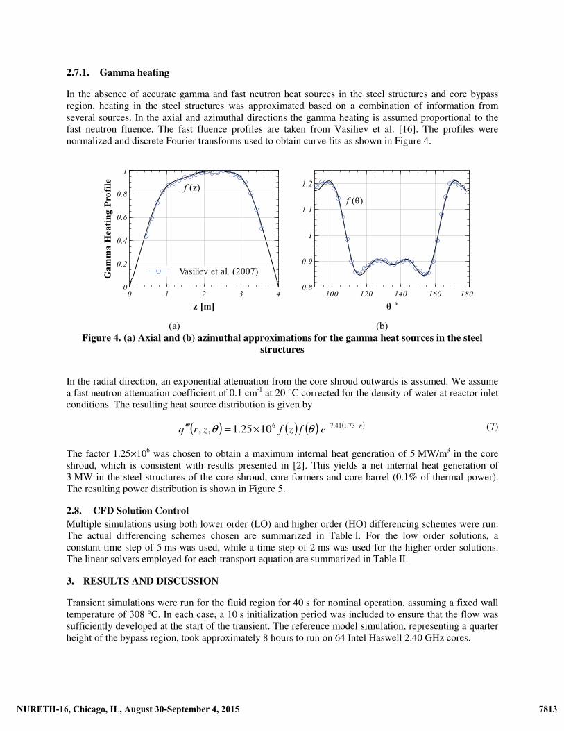
2.7.1. Gamma heating
In the absence of accurate gamma and fast neutron heat sources in the steel structures and core bypass region, heating in the steel structures was approximated based on a combination of information from several sources. In the axial and azimuthal directions the gamma heating is assumed proportional to the fast neutron fluence. The fast fluence profiles are taken from Vasiliev et al. [16]. The profiles were normalized and discrete Fourier transforms used to obtain curve fits as shown in Figure 4.
(a) (b)
Figure 4. (a) Axial and (b) azimuthal approximations for the gamma heat sources in the steel structures
In the radial direction, an exponential attenuation from the core shroud outwards is assumed. We assume a fast neutron attenuation coefficient of 0.1 cm-1 at 20 °C corrected for the density of water at reactor inlet conditions. The resulting heat source distribution is given by
( ) ( ) ( ) ( )refzfzrq −−×=′′′ 73.141.761025.1,, θθ (7)
The factor 1.25×10⁶ was chosen to obtain a maximum internal heat generation of 5 MW/m3 in the core shroud, which is consistent with results presented in [2]. This yields a net internal heat generation of 3 MW in the steel structures of the core shroud, core formers and core barrel (0.1% of thermal power). The resulting power distribution is shown in Figure 5.
2.8. CFD Solution Control Multiple simulations using both lower order (LO) and higher order (HO) differencing schemes were run. The actual differencing schemes chosen are summarized in Table I. For the low order solutions, a constant time step of 5 ms was used, while a time step of 2 ms was used for the higher order solutions. The linear solvers employed for each transport equation are summarized in Table II.
3. RESULTS AND DISCUSSION
Transient simulations were run for the fluid region for 40 s for nominal operation, assuming a fixed wall temperature of 308 °C. In each case, a 10 s initialization period was included to ensure that the flow was sufficiently developed at the start of the transient. The reference model simulation, representing a quarter height of the bypass region, took approximately 8 hours to run on 64 Intel Haswell 2.40 GHz cores.
7814NURETH-16, Chicago, IL, August 30-September 4, 2015 7813NURETH-16, Chicago, IL, August 30-September 4, 2015

Figure 5. Assumed gamma heat source distribution in the steel structures
Table I. Summary of discretization schemes
Equation operator Low order solution Higher order solution Time derivative Euler implicit 2nd order backward
Convection Upwind Limited linear TVD Diffusion Gaussian integration with
linear differencing Gaussian integration with
linear differencing Pressure gradient Gaussian integration with
linear interpolation 2nd order least squares
Table II. Summary of linear solvers
Equation (Solution variable)
Linear solver Comments
Momentum (u�
) Bi-conjugate Gradient DILU preconditioner Continuity (p) Geometric Algebraic Multigrid Gauss Seidel smoother
Turbulence (k, �, �) Bi-conjugate Gradient DILU preconditioner Energy (T) Bi-conjugate Gradient DILU preconditioner
Time-averaged values for the major flow parameters were calculated. These are summarized in Table III below for several RANS turbulence models and mesh refinements. Independent simulations were also run using the commercial software Star-CCM+ [18]. In general the pressure drop is approximately 200 Pa/m and the average wall heat transfer coefficient is consistently in the order of 5-6 kW/m2K. A value of 8.5 kW/m2K is proposed in [2]. The maximum heat transfer coefficient predicted by Star-CCM+, is significantly larger than that by OpenFOAM. In all simulations, this peak value is located on the lower edges of the perforations in the core formers where the heat transfer characteristics are highly sensitive to the local mesh size and boundary layer thickness. This is a localized effect, which has minimal impact on the overall heat transfer behavior of the model.
7815NURETH-16, Chicago, IL, August 30-September 4, 2015 7814NURETH-16, Chicago, IL, August 30-September 4, 2015

Table III. Comparison of solution parameters for different meshes, turbulence models and solution methods
���������� ����� +avgy � +
maxy � PΔ �������� avgh ��� maxh �
������Coarse mesh (2.4 M cells)
k-� Realizable k-� k-� SST k-� (HO) Realizable k-� (HO)
233 / 873 177/703
178 / 540 263/1090 235/869
187 181 192 205 197
5153 / 15163 3961/10854
5347 / 17681 5634/17813 5008/15575
Boundary refined (3 M cells) k-�
86 / 307
196
5297 / 16831
Refined mesh (4 M cells) k-� k-� (HO) Realizable k-� (HO)
98/328
102/377 94.4/328
208 208
189.7
5881 / 17649 6058 /19729 5610/16722
STAR-CCM+ (4.8 M cells) Realizable k-�
124 / 389
197
5317 / 28682
For the remainder of this work, the refined mesh was chosen using the standard k-� turbulence model and higher order discretization schemes (see Table I). The time-variation of pressure drop and heat flux due to vortex shedding downstream of the core formers is shown in Figure 6. These vortices are clearly visible in the top-left figure of Figure 7. The time-averaged velocity and wall heat transfer coefficient are similarly included in this figure.
Figure 6. Time-dependent variation in pressure drop and wall heat flux for the reference solution
Using this time-averaged information, heat transfer simulations for the full height of the core bypass were conducting using both approaches proposed in Section 2.3. Figure 8 shows the shroud outer surface temperature for both approaches assuming no gamma heating. The first approach yields results with sharper, more resolved features, which is likely an artifact of the method. The second approach shows more diffuse features, which is an expected consequence of the time-averaging, but overpredicts the temperatures on the periphery (left and right sides) of the model. This is a result of the simple model
7816NURETH-16, Chicago, IL, August 30-September 4, 2015 7815NURETH-16, Chicago, IL, August 30-September 4, 2015

employed for the heat transfer, which only takes into account the axial variation in bulk coolant temperature and assumes a constant flow distribution.
As expected, there is a marked difference in steel structure temperatures if gamma heating is included (see Figure 9). There is distinct peaking in shroud temperatures in the corners closest to the core, coincident with the gamma heat source maxima. The temperatures shown in Figure 9 are comparable with those of [2], which show a peak temperature of 329 °C.
Figure 7. Instantaneous (top-left) and time-averaged velocity (bottom-left) and heat transfer
coefficient (right) for the reference solution
(a) (b)
Figure 8. Unfolded shroud outer surface temperatures, neglecting the gamma heat sources in the core bypass region, obtained using the (a) first and (b) second approaches
Far less noticeable is the bulk temperature rise in the core bypass (Figure 10). If gamma heat sources are excluded, the primary source of heating in the core bypass is by direct conduction from the core through the core shroud. In this case the temperature rise in the core bypass is very small. If gamma heating is
7817NURETH-16, Chicago, IL, August 30-September 4, 2015 7816NURETH-16, Chicago, IL, August 30-September 4, 2015

included the bulk temperature rise is more significant since a large fraction of the gamma heating is removed directly by the core bypass flow. The absolute temperature rise in this case is highly approximate because the true gamma heating in the steel structures is at this stage not known. However, based on the simulation results one can conclude that approximately 60% of the gamma heating in the steel structures is removed by convection in the core bypass region and the remainder is removed in the downcomer and core regions. Assuming a uniform gamma heat source of 0.2 MW/m3 in the coolant [17] increases the bypass temperature at the top of the core by a further 2 °C.
Figure 9. Steel structure temperatures obtained using the second approach with approximated
heating in the steel structures
(a) (b)
Figure 10. Bulk fluid temperature in the core bypass using (a) no gamma heat source and (b) gamma heat sources in the steel structures
In both approaches the most significant portion of the required computational effort is in obtaining the initial transient CFD solution for the fluid. Consequently, neither approach is computationally more
7818NURETH-16, Chicago, IL, August 30-September 4, 2015 7817NURETH-16, Chicago, IL, August 30-September 4, 2015

efficient. While conceptually very simple, the first approach assumes that the flow information is separable in time, which has no real physical or mathematical justification. As an independent verification this approach has proven useful in this work, however future work will likely focus on the second approach, since it has a more physically consistent basis.
4. CONCLUSIONS
Initial results have been presented for the CFD analysis of a Siemens KWU PWR with a focus on the flow behavior and heat transfer in the gap between the core shroud and core barrel. Temperatures and densities in this region of the reactor are important for accurate estimations of fast neutron fluence and activation in the steel structures of the core shroud, core barrel and reactor pressure vessel. First simulations of the flow in this region showed that the flow is in a transitional state, with vortex shedding taking place downstream of the core formers. The non-stationary nature of the flow presented a challenge in terms of obtaining a solution within a reasonable time period. Two approaches were proposed to address this challenge; Time-averaging of the flow-field information before solving the conjugate heat transfer problem and time-averaging of surface heat fluxes in order to derive detailed surface heat transfer coefficients. Both approaches yielded similar results with similar computational effort, although the second approach has a more physically consistent basis. This work confirms that, on its own, the heat transfer from the core to the core bypass has a negligible impact on the core bypass temperature. Simulations using an approximated gamma heating map have confirmed that the gamma heating within the steel structures increases the temperatures in these structures noticeably. It is therefore important that accurate values for the gamma heating in the steel structures, obtained using Monte Carlo analysis or other methods, be known. This work is a first step in the STARS project towards coupled CFD / Monte Carlo simulations for the accurate prediction of temperatures and fast neutron fluence in the steel structures of the core.
5. ACKNOWLEDGMENTS
This work was partly funded by the Swiss Federal Nuclear Safety Inspectorate ENSI (Eidgenössisches Nuklearsicherheitsinspektorat), within the framework of the STARS project (http://stars.web.psi.ch).
6. REFERENCES
1. P. Petrequin, R. Pelli, P. Soulat and A.A. Tavassoli, “Effect of Irradiation on Water Reactors Internals (Including Russion WWER),” Study Contract COSU CT94-074, CEA (France), TECNATOM (Spain) and VTT (Finland) (1997).
2. E. Altstadt, H. Kumpf, F.P. Weiss, E. Fischer, G. Nagel, G. Sgarz, “Analysis of a PWR core baffle considering irradiation induced creep,” Annals of Nuclear Energy, 31(7), pp. 723-736 (2004).
3. I. Rupp, P. Christophe and M. Tommy, “Large Scale Finite Element Thermal Analysis of the Bolts of a French PWR Core Internal Baffle Structure,” Nuclear Engineering and Technology, 41(9), pp. 1171-1180 (2009).
4. “Steady-state and Transient Analysis Research for the Swiss Reactors,” https://stars.web.psi.ch (under maintenance) (2015).
5. H.G. Weller, G. Tabor, H. Jasak, C. Fureby, “A tensorial approach to computational continuum mechanics using object-oriented techniques,” Computers in physics, 12, pp. 620 (1998).
6. I.P. Castro, “Wake characteristics of two-dimensional perforated plates normal to an air stream,” Journal of Fluid Mechanics, 6(3), pp. 599-609 (1971).
7. H.K. Versteeg and W. Malalasekera, “An Introduction to Computational Fluid Dynamics: The Finite Volume Method,” 2nd Ed., Prentice Hall (1995)
8. S.V. Patankar and D.B. Spalding, “A calculation procedure for heat, mass and momentum transfer in three-dimensional parabolic flows,” Int. J. of Heat and Mass Transfer, 15(10), pp. 1787-1806 (1972).
7819NURETH-16, Chicago, IL, August 30-September 4, 2015 7818NURETH-16, Chicago, IL, August 30-September 4, 2015

9. R.I. Issa, “Solution of the Implicitly Discretized Fluid Flow Equation by Operator Splitting,” Journal of Computational Physics, 62, pp. 49–65 (1986).
10. “SolidWorks,” http://www.solidworks.com (2015). 11. W. Wagner et al., “The IAPWS Industrial Formulation 1997 for the Thermodynamic Properties of
Water and Steam,” ASME J. Eng. Gas Turbines and Power, 122, pp. 150-182 (2000). 12. “THERPRO: On-line Nuclear Materials Thermo-physical Properties Database,”
http://therpro.iaea.org (2015). 13. “Creative Fields,” http://www.c-fields.com (2015). 14. H. Jasak, “Error analysis and estimation for the finite volume method with applications to fluid
flows,” PhD thesis: Imperial College London (1996). 15. “Trelis CFD,” http://www.csimsoft.com (2015). 16. A. Vasiliev, H. Ferroukhi, M.A. Zimmermann, R. Chawla, “Development of a CASMO-
4/SIMULATE-3/MCNPX calculation scheme for PWR fast neutron fluence analysis and validation against RPV scraping test data,” Annals of Nuclear Energy, 34(8), pp. 615-627 (2007).
17. C. Peniguel, I. Rupp, I. Ligneau, M. Tommymartin, L. Beloeil, E. Lemaire, “Thermal Analysis of a PWR core internal baffle structure,” ASME 2006 Pressure Vessels and Piping/ICPVT-11 Conference, Vancouver, Canada (2006).
18. “STAR-CCM+,” http://www.cd-adapco.com/products/star-ccm (2015).
7820NURETH-16, Chicago, IL, August 30-September 4, 2015 7819NURETH-16, Chicago, IL, August 30-September 4, 2015