computational fabrication
TRANSCRIPT
Computational Fabrication
Wojciech Matusik, Adriana Schulz

Permission to make digital or hard copies of part or all of this work
for personal or classroom use is granted without fee provided that
copies are not made or distributed for profit or commercial
advantage and that copies bear this notice and the full citation on
the first page.
Copyrights for third-party components of this work must be
honored. For all other uses, contact the Owner/Author.
Copyright is held by the owner/author(s).
SIGGRAPH '19 Courses, July 28 - August 01, 2019, Los Angeles, CA,
USA
ACM 978-1-4503-6307-5/19/07.
10.1145/3305366.3328065

Your lecturers for this course
• Instructors
– Wojciech Matusik, MIT
– Adriana Schulz, UW

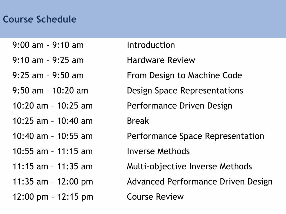
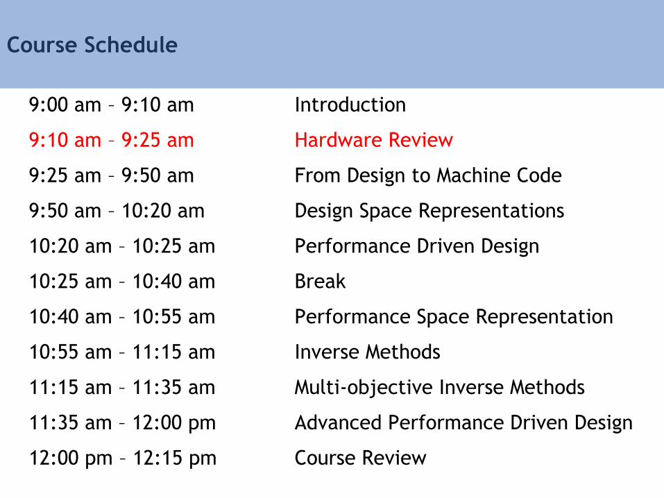
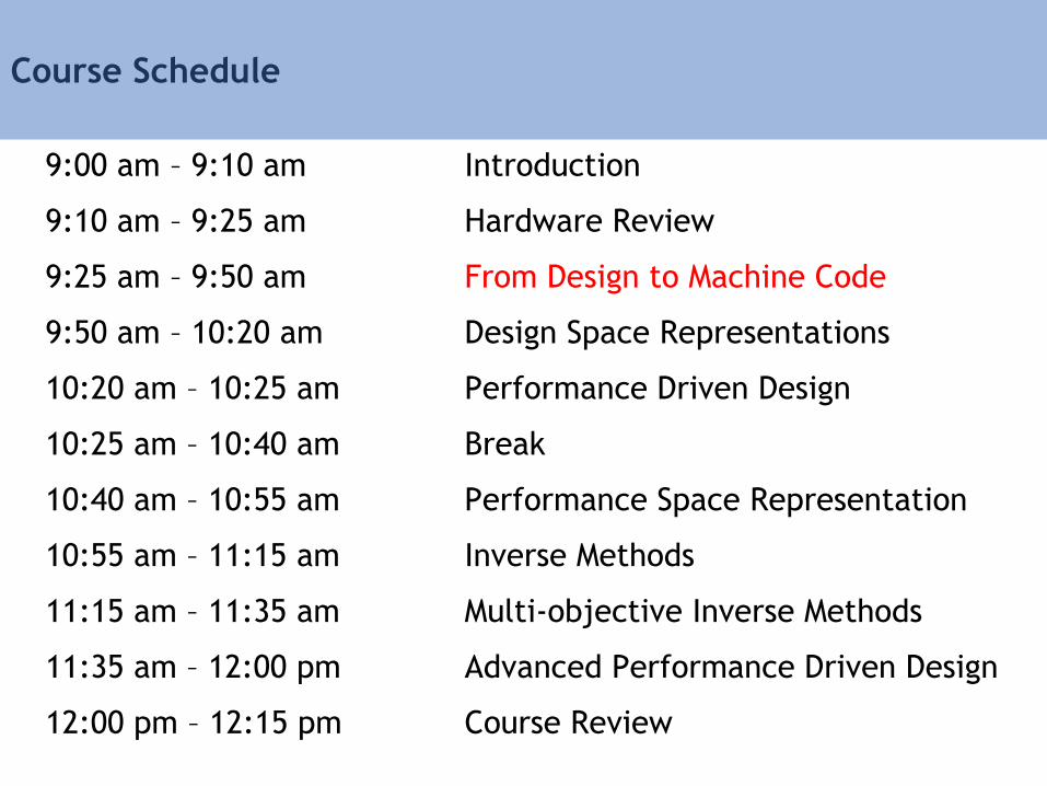
Course Schedule
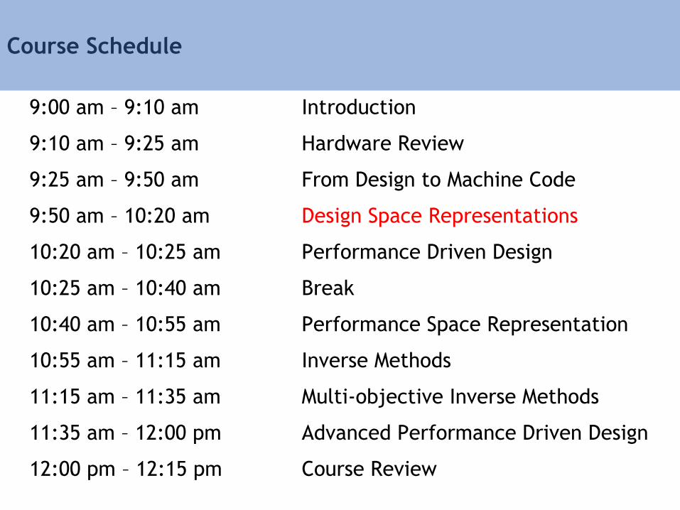
9:00 am – 9:10 am Introduction
9:10 am – 9:25 am Hardware Review
9:25 am – 9:50 am From Design to Machine Code
9:50 am – 10:20 am Design Space Representations
10:20 am – 10:25 am Performance Driven Design
10:25 am – 10:40 am Break
10:40 am – 10:55 am Performance Space Representation
10:55 am – 11:15 am Inverse Methods
11:15 am – 11:35 am Multi-objective Inverse Methods
11:35 am – 12:00 pm Advanced Performance Driven Design
12:00 pm – 12:15 pm Course Review
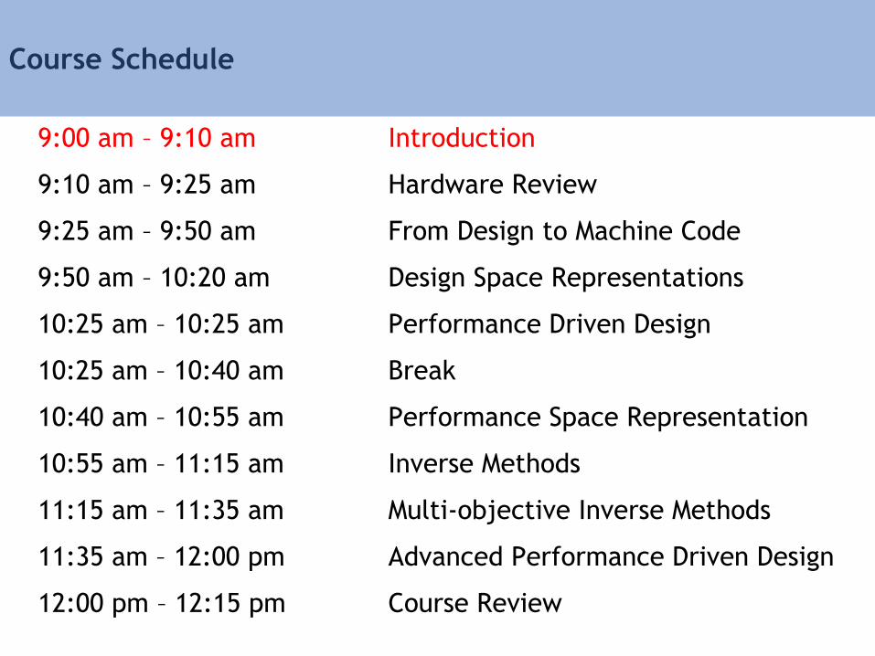
Course Schedule
9:00 am – 9:10 am Introduction
9:10 am – 9:25 am Hardware Review
9:25 am – 9:50 am From Design to Machine Code
9:50 am – 10:20 am Design Space Representations
10:25 am – 10:25 am Performance Driven Design
10:25 am – 10:40 am Break
10:40 am – 10:55 am Performance Space Representation
10:55 am – 11:15 am Inverse Methods
11:15 am – 11:35 am Multi-objective Inverse Methods
11:35 am – 12:00 pm Advanced Performance Driven Design
12:00 pm – 12:15 pm Course Review
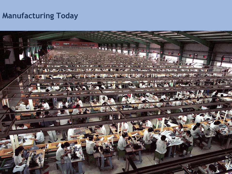
Manufacturing Today
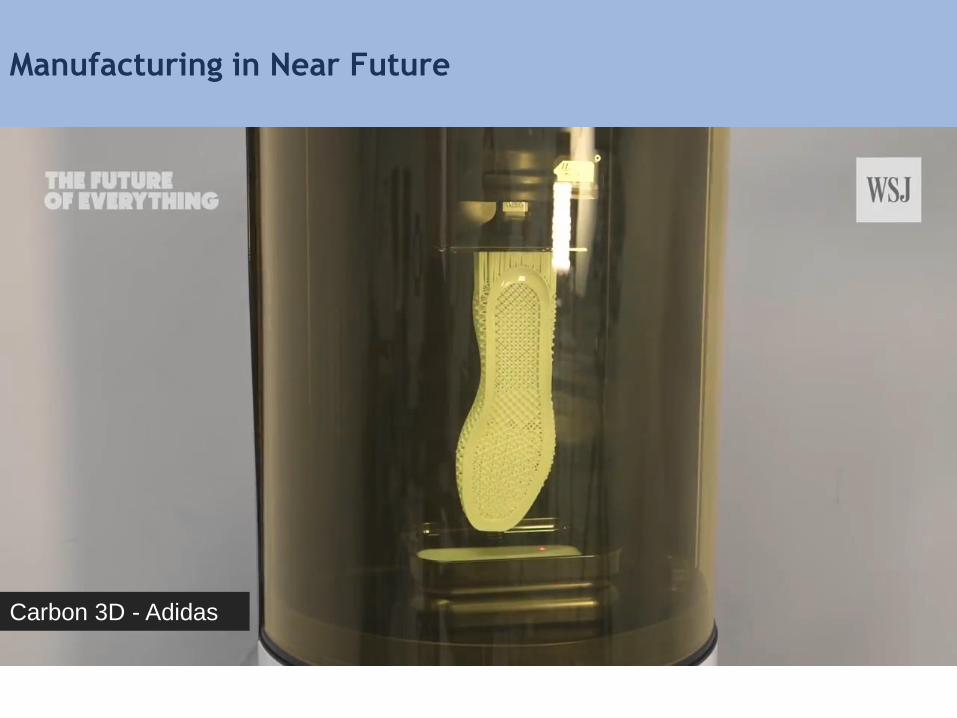
Carbon 3D - Adidas
Manufacturing in Near Future
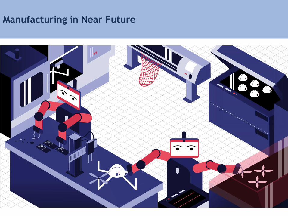
Manufacturing in Near Future
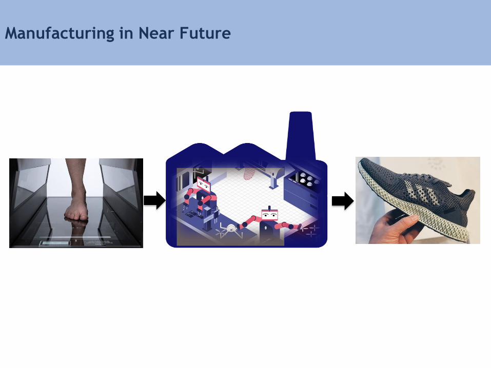
Manufacturing in Near Future

Why Computational Design and Manufacturing?
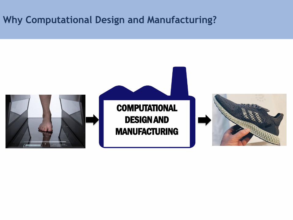
COMPUTATIONAL
DESIGN AND
MANUFACTURING
Why Computational Design and Manufacturing?

Hardware
Hardware
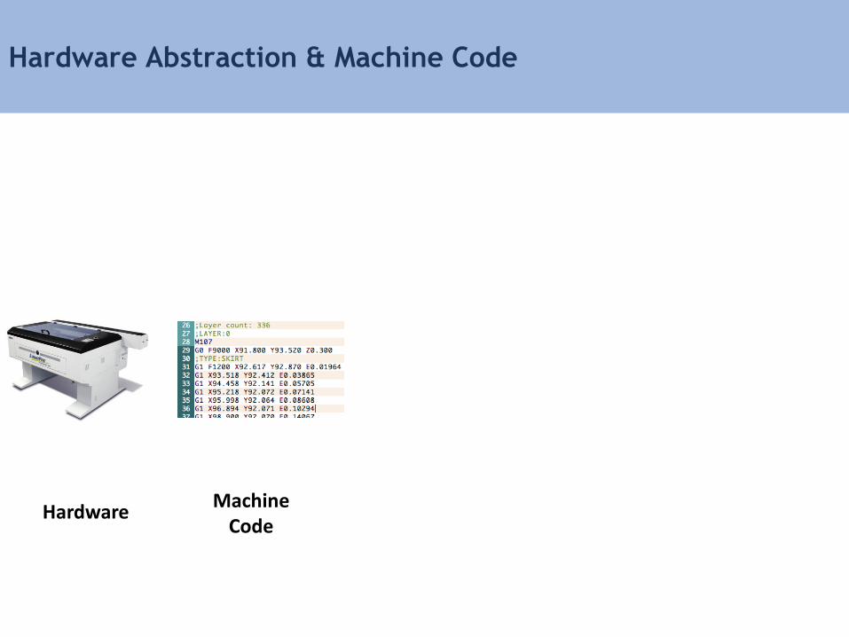
Hardware Abstraction & Machine Code
Machine Code
Hardware
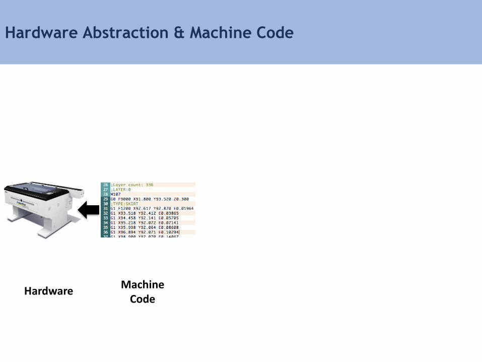
Hardware Abstraction & Machine Code
Machine Code
Hardware
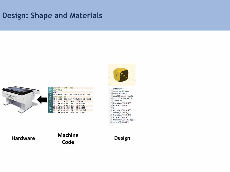
Design: Shape and Materials
Machine Code
Hardware Design

From Design to Machine Code
Machine Code
Hardware Design
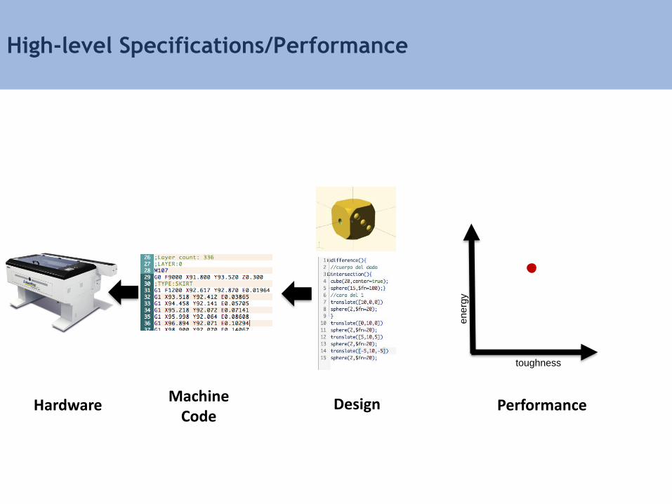
High-level Specifications/Performance
toughness
en
erg
y
Machine Code
PerformanceHardware Design

From Design to Performance
toughness
en
erg
y
Machine Code
Hardware Design Performance
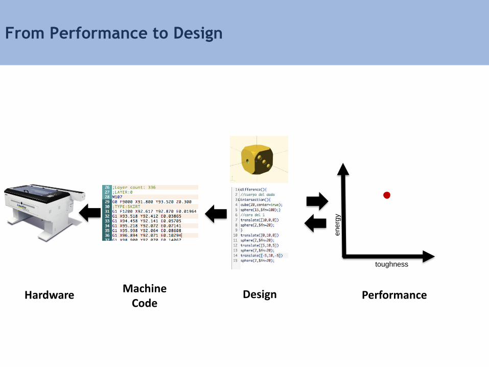
From Performance to Design
toughness
en
erg
y
Machine Code
DesignHardware Performance
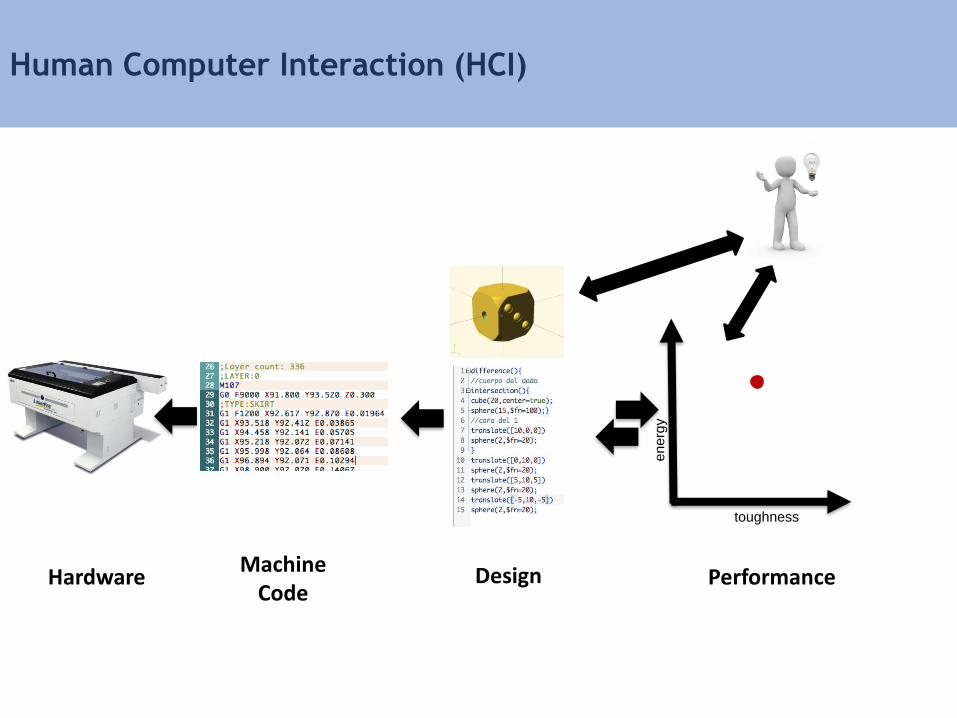
Human Computer Interaction (HCI)
toughness
en
erg
y
Machine Code
Hardware Design Performance
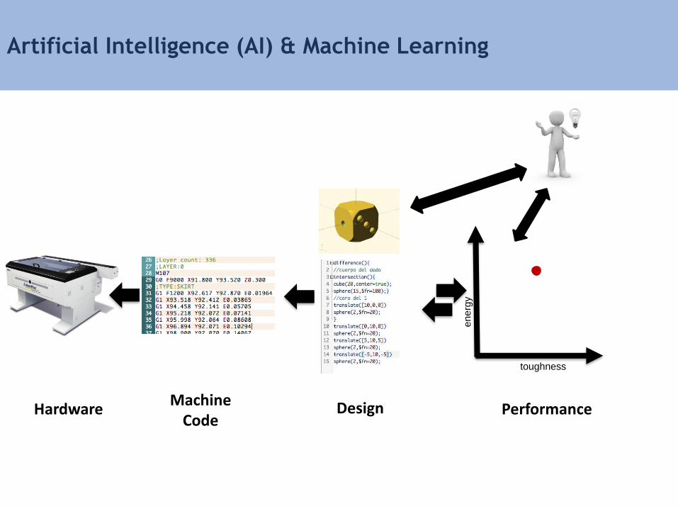
Artificial Intelligence (AI) & Machine Learning
toughness
en
erg
y
Machine Code
Hardware Design Performance

Operating Systems for Future Factory
• Multi-tasking
• Distributed systems

Who’s working on this?
Highly interdisciplinary field!
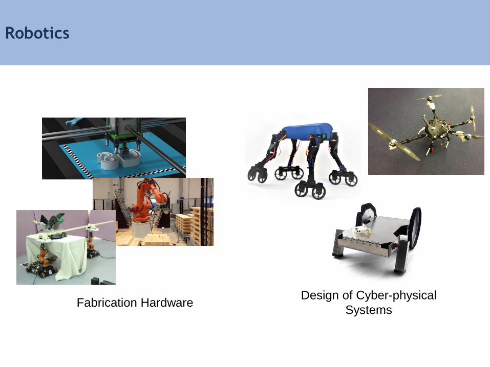
Robotics
Fabrication HardwareDesign of Cyber-physical
Systems
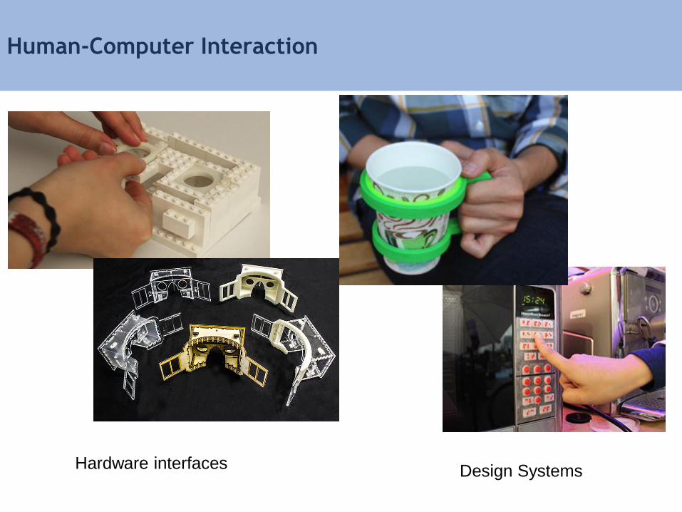
Human-Computer Interaction
Hardware interfaces Design Systems

Computer Graphics
Performance-Driven DesignGeometry Processing
Computer Science
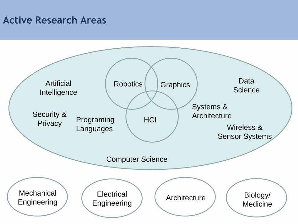
Active Research Areas
Programing
Languages
Artificial
Intelligence
Security &
PrivacyWireless &
Sensor Systems
Data
Science
Architectu
re
Electrical
Engineering
Architectu
reArchitecture BiologyBiology/
Medicine Biology
Mechanical
Engineering
Robotics
HCI
Graphics
Systems &
Architecture
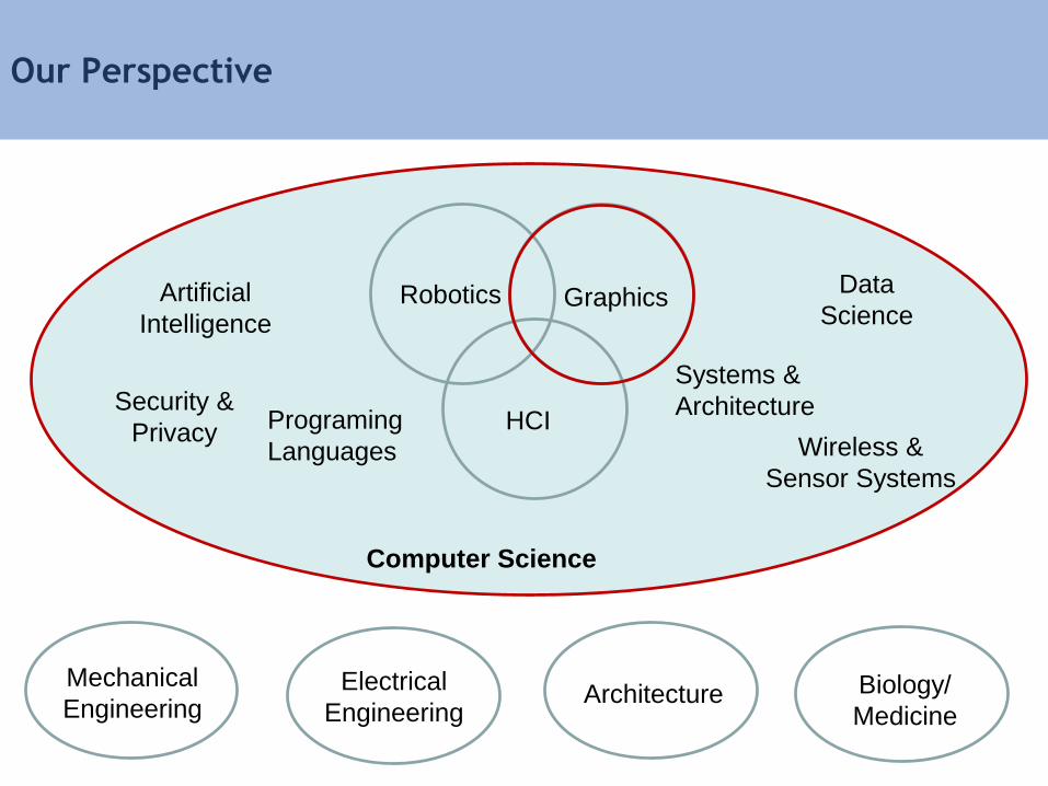
Computer Science
Our Perspective
Programing
Languages
Artificial
Intelligence
Security &
PrivacyWireless &
Sensor Systems
Data
Science
Architectu
re
Electrical
Engineering
Architectu
reArchitecture BiologyBiology/
Medicine Biology
Mechanical
Engineering
Robotics
HCI
Graphics
Systems &
Architecture
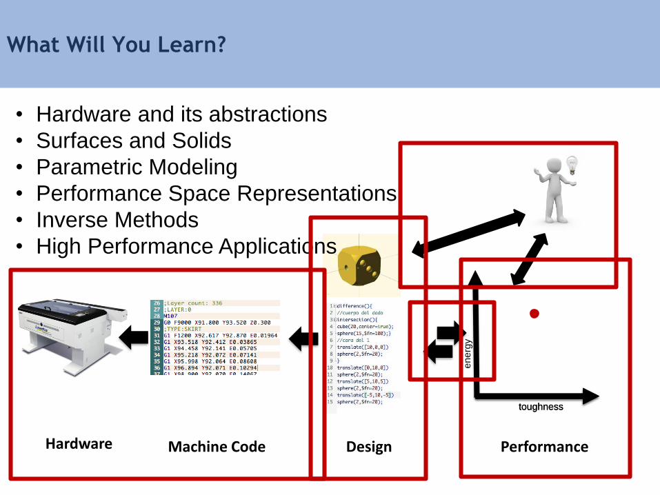
What Will You Learn?
toughness
en
erg
y
• Hardware and its abstractions
• Surfaces and Solids
• Parametric Modeling
• Performance Space Representations
• Inverse Methods
• High Performance Applications
toughness
Machine Code PerformanceHardware Design
Course Schedule
9:00 am – 9:10 am Introduction
9:10 am – 9:25 am Hardware Review
9:25 am – 9:50 am From Design to Machine Code
9:50 am – 10:20 am Design Space Representations
10:20 am – 10:25 am Performance Driven Design
10:25 am – 10:40 am Break
10:40 am – 10:55 am Performance Space Representation
10:55 am – 11:15 am Inverse Methods
11:15 am – 11:35 am Multi-objective Inverse Methods
11:35 am – 12:00 pm Advanced Performance Driven Design
12:00 pm – 12:15 pm Course Review
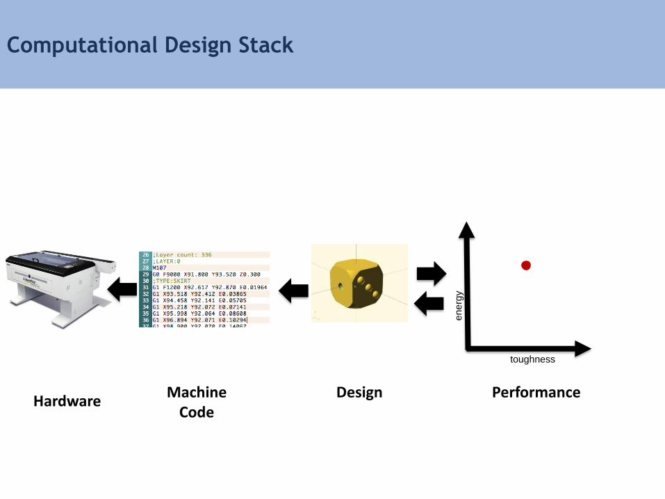
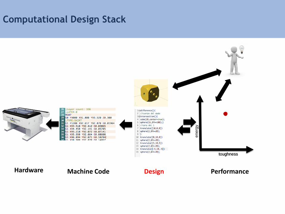
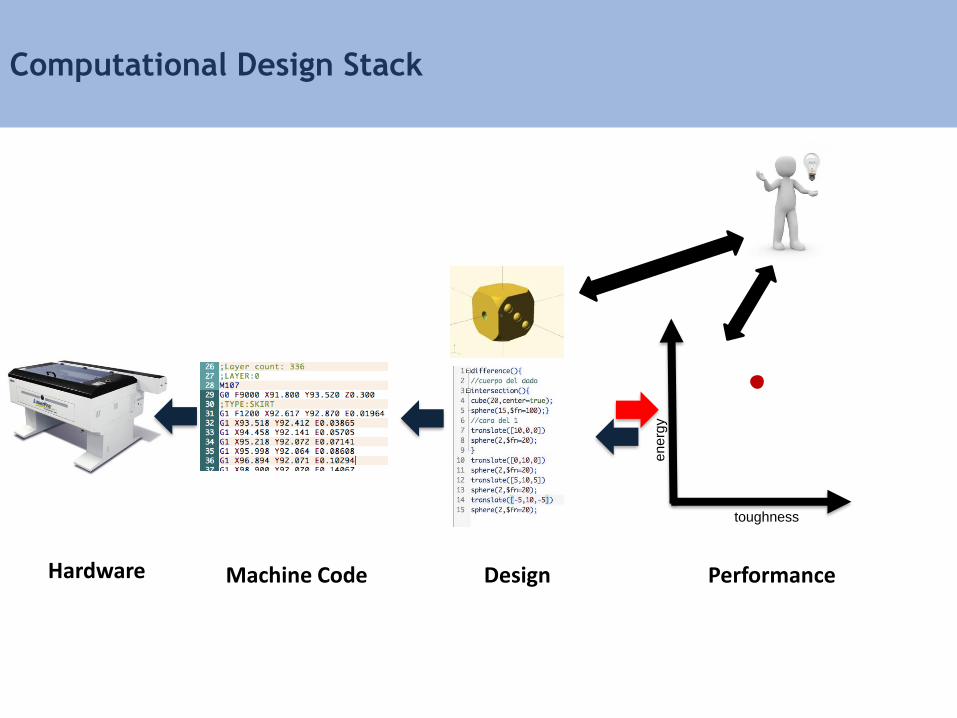
Computational Design Stack
toughness
en
erg
y
Machine Code
Design PerformanceHardware
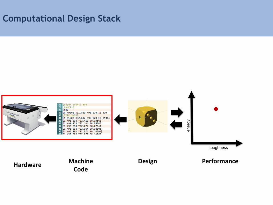
Computational Design Stack
toughness
en
erg
y
Machine Code
Design PerformanceHardware

Subtractive Manufacturing
• Start with a block of material
• Remove material to obtain a given shape
Source: https://commons.wikimedia.org
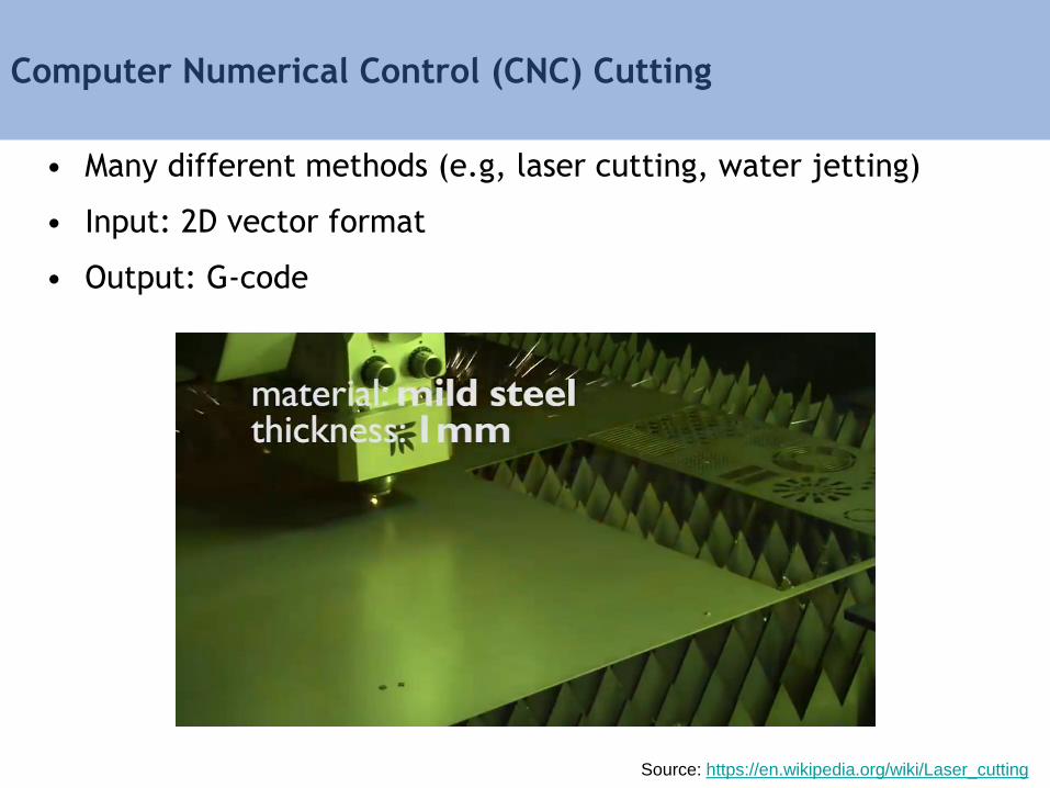
Computer Numerical Control (CNC) Cutting
• Many different methods (e.g, laser cutting, water jetting)
• Input: 2D vector format
• Output: G-code
Source: https://en.wikipedia.org/wiki/Laser_cutting

3-Axis CNC Milling/Engraving
• Input: 2.5D (heightfield)
• Output: G-code, multiple passes
Source: https://www.youtube.com/watch?v=uE-49w6JtTk
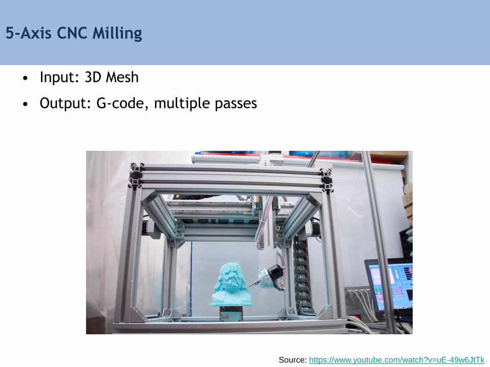
5-Axis CNC Milling
• Input: 3D Mesh
• Output: G-code, multiple passes
Source: https://www.youtube.com/watch?v=uE-49w6JtTk
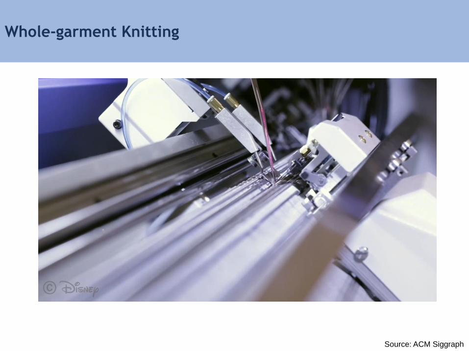
Whole-garment Knitting
Source: ACM Siggraph

3D Printing Basics
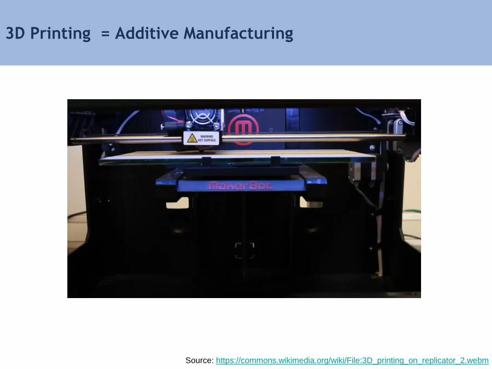
3D Printing = Additive Manufacturing
Source: https://commons.wikimedia.org/wiki/File:3D_printing_on_replicator_2.webm
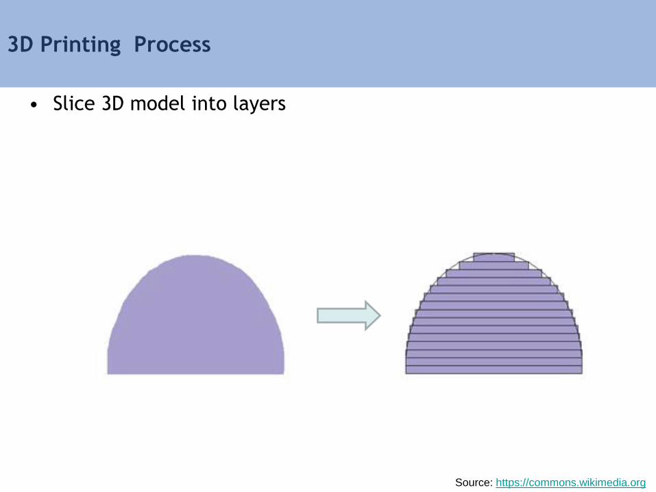
3D Printing Process
• Slice 3D model into layers
Source: https://commons.wikimedia.org

3D Printing Process
• Slice 3D model into layers
• Manufacture layers one by one (e.g., bottom-up)
Source: https://commons.wikimedia.org
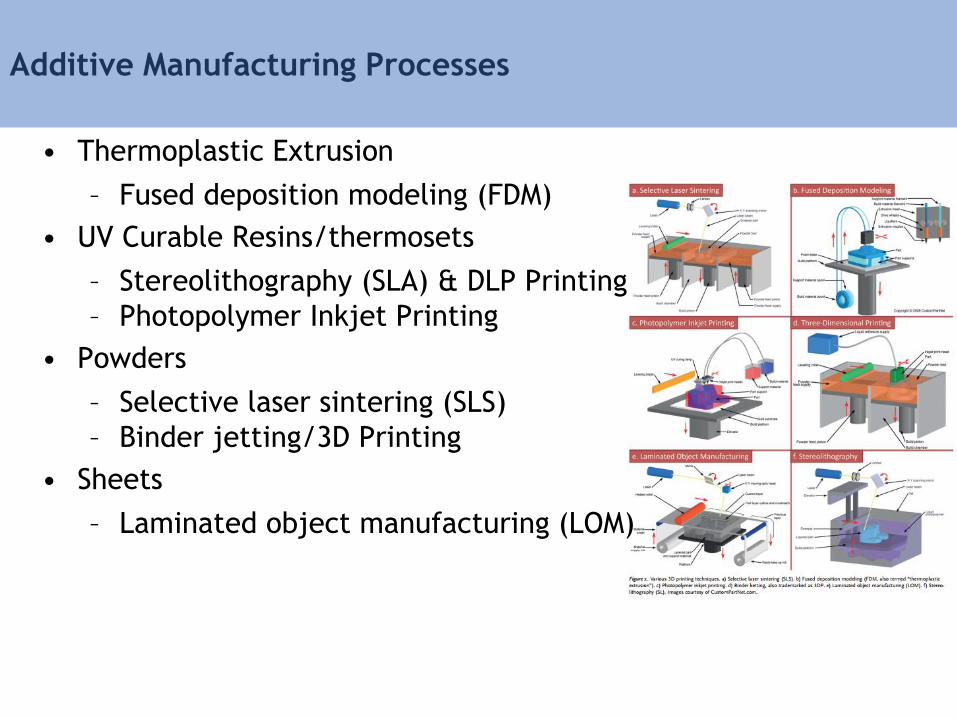
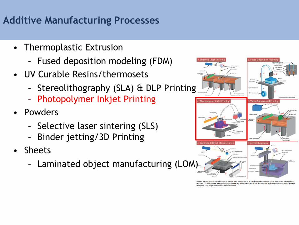
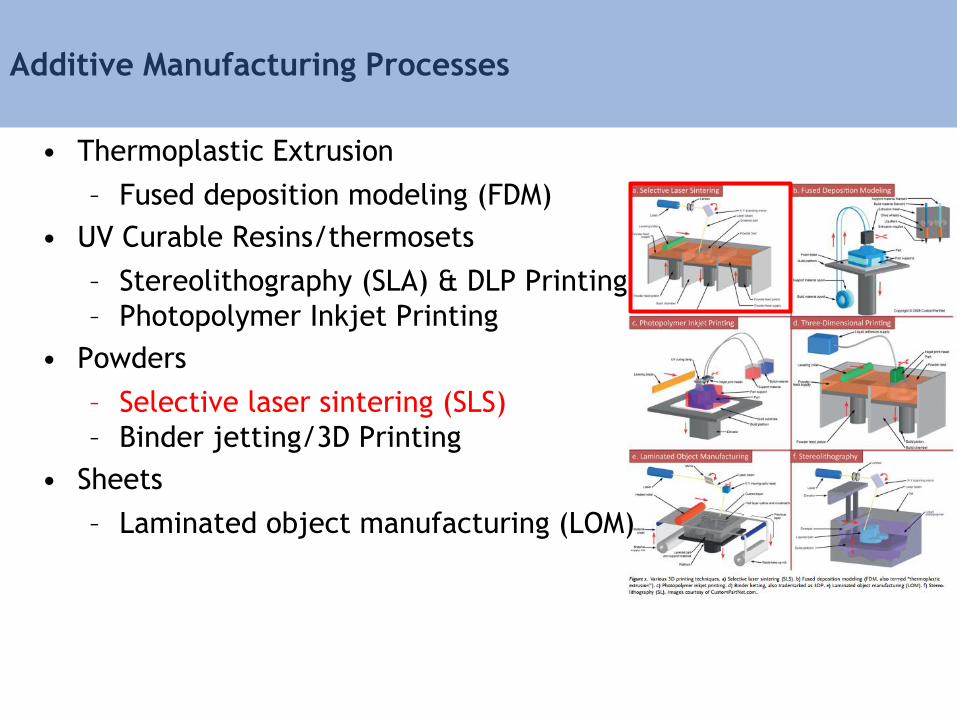
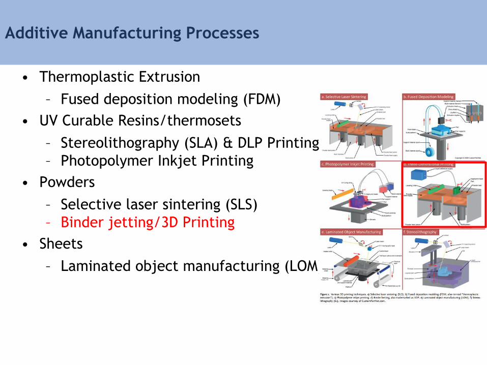
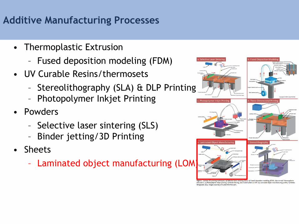
Additive Manufacturing Processes
• Thermoplastic Extrusion
– Fused deposition modeling (FDM)
• UV Curable Resins/thermosets
– Stereolithography (SLA) & DLP Printing
– Photopolymer Inkjet Printing
• Powders
– Selective laser sintering (SLS)
– Binder jetting/3D Printing
• Sheets
– Laminated object manufacturing (LOM)
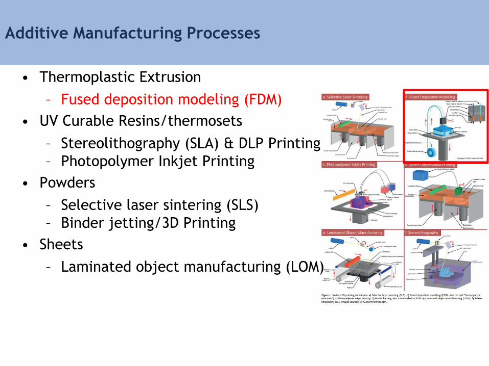
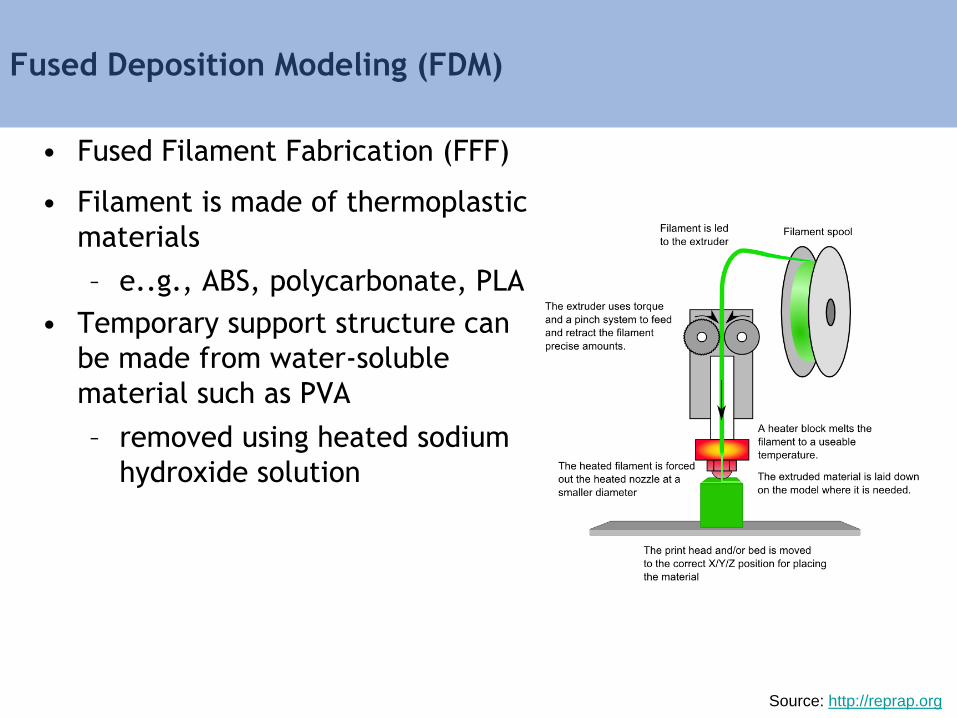
Fused Deposition Modeling (FDM)
• Fused Filament Fabrication (FFF)
• Filament is made of thermoplastic
materials
– e..g., ABS, polycarbonate, PLA
• Temporary support structure can
be made from water-soluble
material such as PVA
– removed using heated sodium
hydroxide solution
Source: http://reprap.org

Additive Manufacturing Processes
• Thermoplastic Extrusion
– Fused deposition modeling (FDM)
• UV Curable Resins/thermosets
– Stereolithography (SLA) & DLP Printing
– Photopolymer Inkjet Printing
• Powders
– Selective laser sintering (SLS)
– Binder jetting/3D Printing
• Sheets
– Laminated object manufacturing (LOM)
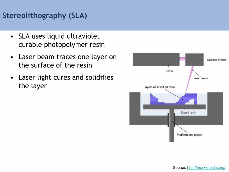
Stereolithography (SLA)
• SLA uses liquid ultraviolet
curable photopolymer resin
• Laser beam traces one layer on
the surface of the resin
• Laser light cures and solidifies
the layer
Source: http://en.wikipedia.org/
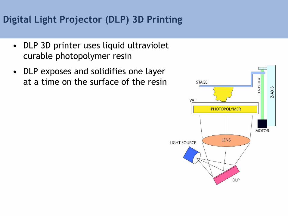
Digital Light Projector (DLP) 3D Printing
• DLP 3D printer uses liquid ultraviolet
curable photopolymer resin
• DLP exposes and solidifies one layer
at a time on the surface of the resin

DLP 3D Printing Process
Additive Manufacturing Processes
• Thermoplastic Extrusion
– Fused deposition modeling (FDM)
• UV Curable Resins/thermosets
– Stereolithography (SLA) & DLP Printing
– Photopolymer Inkjet Printing
• Powders
– Selective laser sintering (SLS)
– Binder jetting/3D Printing
• Sheets
– Laminated object manufacturing (LOM)
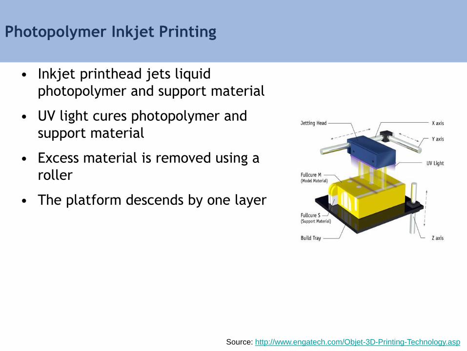
Photopolymer Inkjet Printing
• Inkjet printhead jets liquid
photopolymer and support material
• UV light cures photopolymer and
support material
• Excess material is removed using a
roller
• The platform descends by one layer
Source: http://www.engatech.com/Objet-3D-Printing-Technology.asp
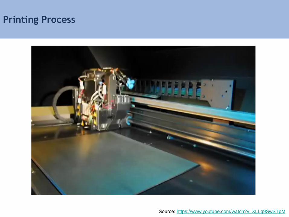
Printing Process
Source: https://www.youtube.com/watch?v=XLLq9SwSTpM
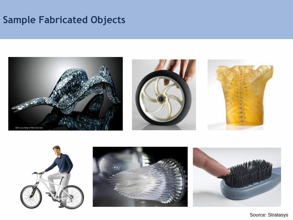
Sample Fabricated Objects
Source: Stratasys
Additive Manufacturing Processes
• Thermoplastic Extrusion
– Fused deposition modeling (FDM)
• UV Curable Resins/thermosets
– Stereolithography (SLA) & DLP Printing
– Photopolymer Inkjet Printing
• Powders
– Selective laser sintering (SLS)
– Binder jetting/3D Printing
• Sheets
– Laminated object manufacturing (LOM)
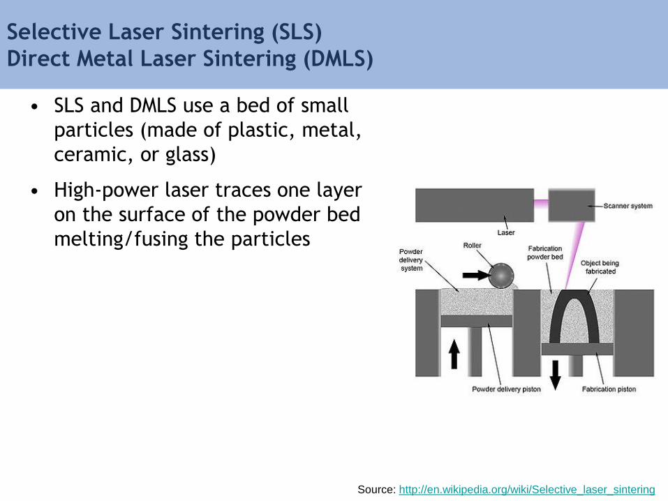
Selective Laser Sintering (SLS)
Direct Metal Laser Sintering (DMLS)
• SLS and DMLS use a bed of small
particles (made of plastic, metal,
ceramic, or glass)
• High-power laser traces one layer
on the surface of the powder bed
melting/fusing the particles
Source: http://en.wikipedia.org/wiki/Selective_laser_sintering
SLS & DMLS Process
Source: https://www.youtube.com/watch?v=BZLGLzyMKn4

Sample Fabricated Parts
Source: http://www.bridgesmathart.org , http://www.freedomofcreation.com
Additive Manufacturing Processes
• Thermoplastic Extrusion
– Fused deposition modeling (FDM)
• UV Curable Resins/thermosets
– Stereolithography (SLA) & DLP Printing
– Photopolymer Inkjet Printing
• Powders
– Selective laser sintering (SLS)
– Binder jetting/3D Printing
• Sheets
– Laminated object manufacturing (LOM)
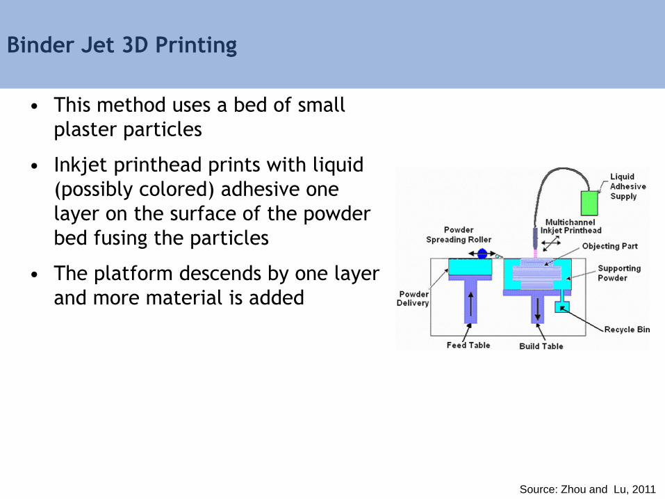
Binder Jet 3D Printing
• This method uses a bed of small
plaster particles
• Inkjet printhead prints with liquid
(possibly colored) adhesive one
layer on the surface of the powder
bed fusing the particles
• The platform descends by one layer
and more material is added
Source: Zhou and Lu, 2011
Binder Jet 3D Printing Process
Source: https://www.youtube.com/watch?v=GnFxujCyD70
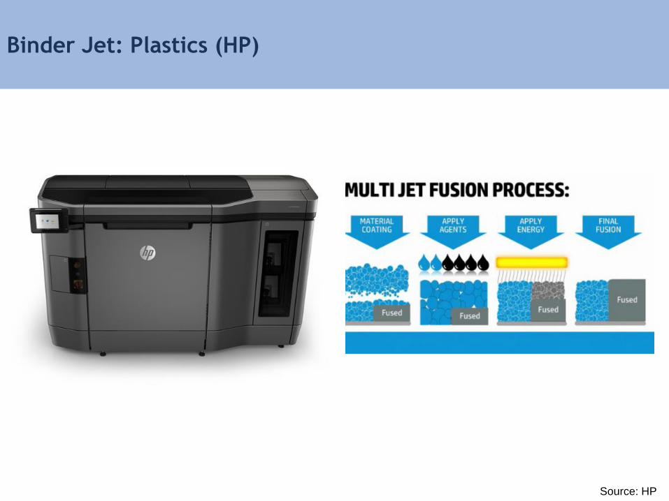
Binder Jet: Plastics (HP)
Source: HP
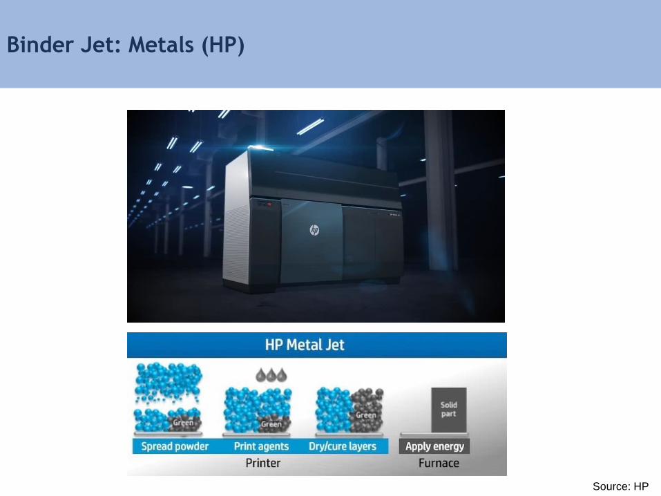
Binder Jet: Metals (HP)
Source: HP
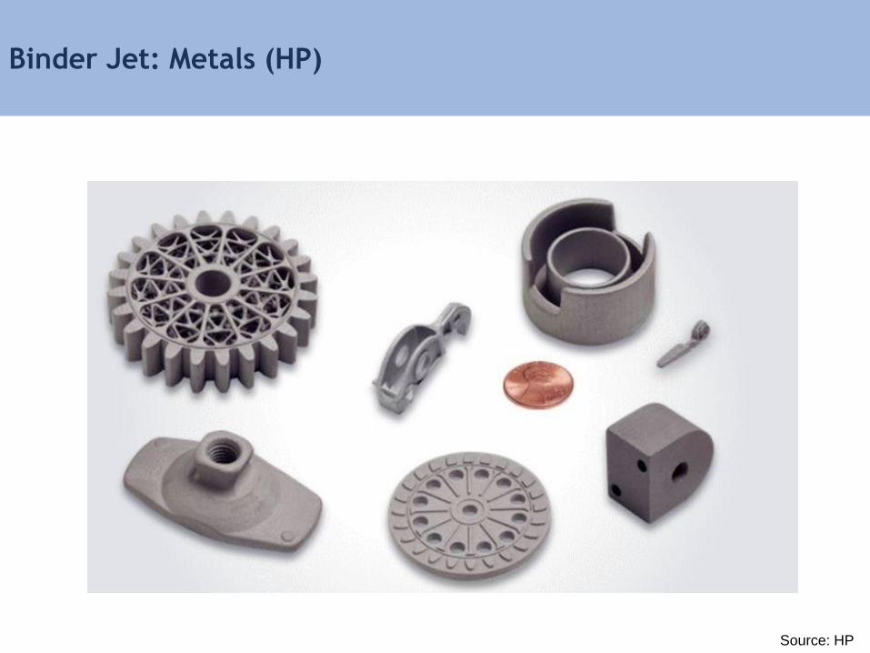
Binder Jet: Metals (HP)
Source: HP
Additive Manufacturing Processes
• Thermoplastic Extrusion
– Fused deposition modeling (FDM)
• UV Curable Resins/thermosets
– Stereolithography (SLA) & DLP Printing
– Photopolymer Inkjet Printing
• Powders
– Selective laser sintering (SLS)
– Binder jetting/3D Printing
• Sheets
– Laminated object manufacturing (LOM)
Course Schedule
9:00 am – 9:10 am Introduction
9:10 am – 9:25 am Hardware Review
9:25 am – 9:50 am From Design to Machine Code
9:50 am – 10:20 am Design Space Representations
10:20 am – 10:25 am Performance Driven Design
10:25 am – 10:40 am Break
10:40 am – 10:55 am Performance Space Representation
10:55 am – 11:15 am Inverse Methods
11:15 am – 11:35 am Multi-objective Inverse Methods
11:35 am – 12:00 pm Advanced Performance Driven Design
12:00 pm – 12:15 pm Course Review
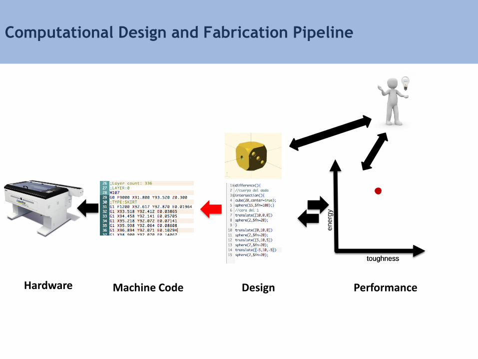
Computational Design and Fabrication Pipeline
toughness
en
erg
y
toughness
Machine Code PerformanceHardware Design
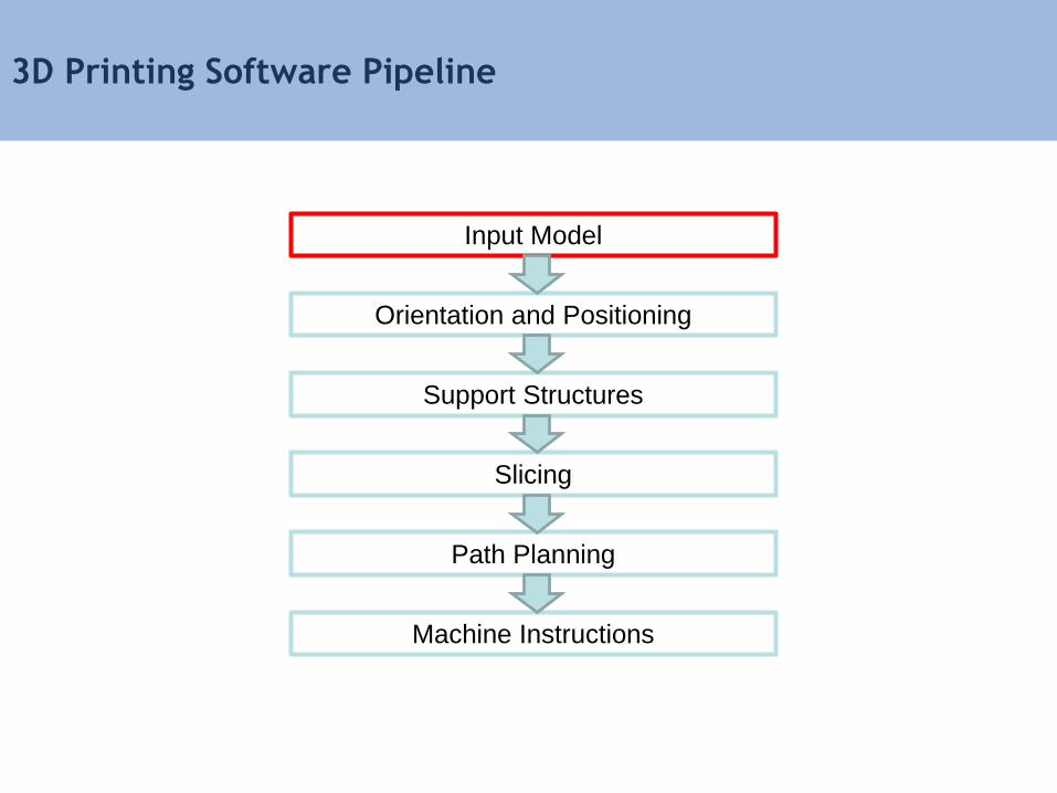
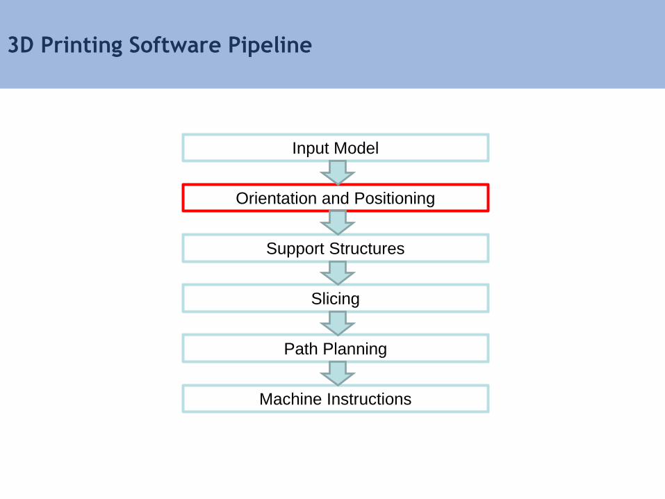
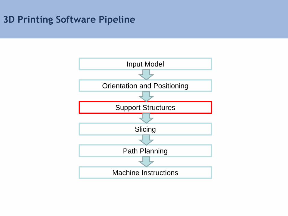
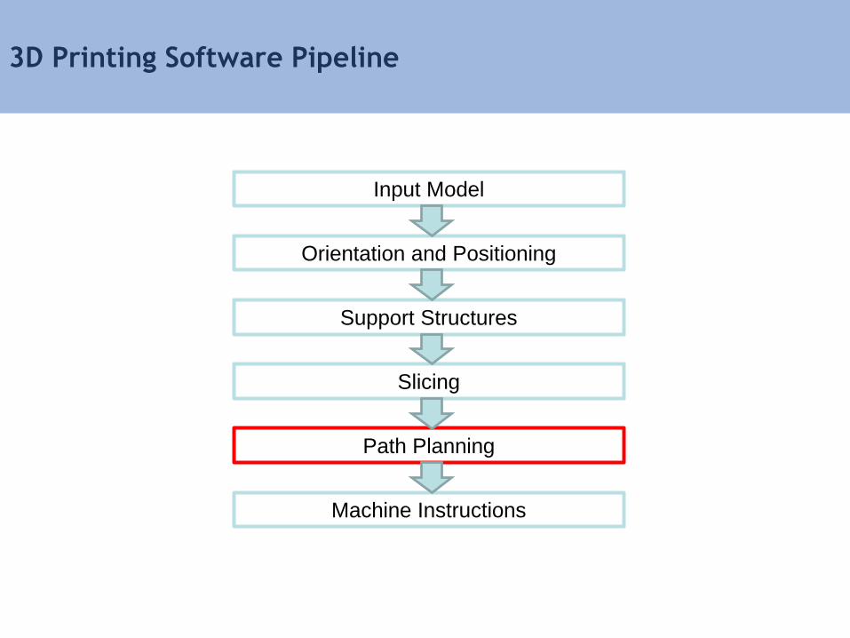
3D Printing Software Pipeline
Input Model
Orientation and Positioning
Support Structures
Slicing
Path Planning
Machine Instructions
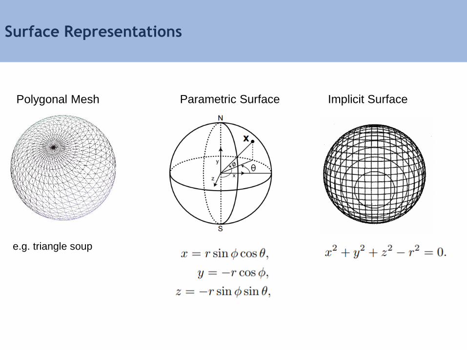
Parametric Surface
Surface Representations
Implicit SurfacePolygonal Mesh
e.g. triangle soup
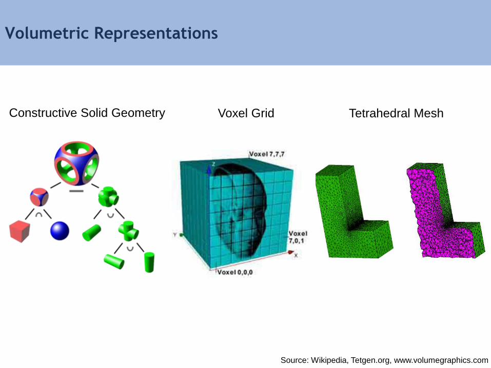
Volumetric Representations
Source: Wikipedia, Tetgen.org, www.volumegraphics.com
Tetrahedral MeshConstructive Solid Geometry Voxel Grid
3D Printing Software Pipeline
Input Model
Orientation and Positioning
Support Structures
Slicing
Path Planning
Machine Instructions
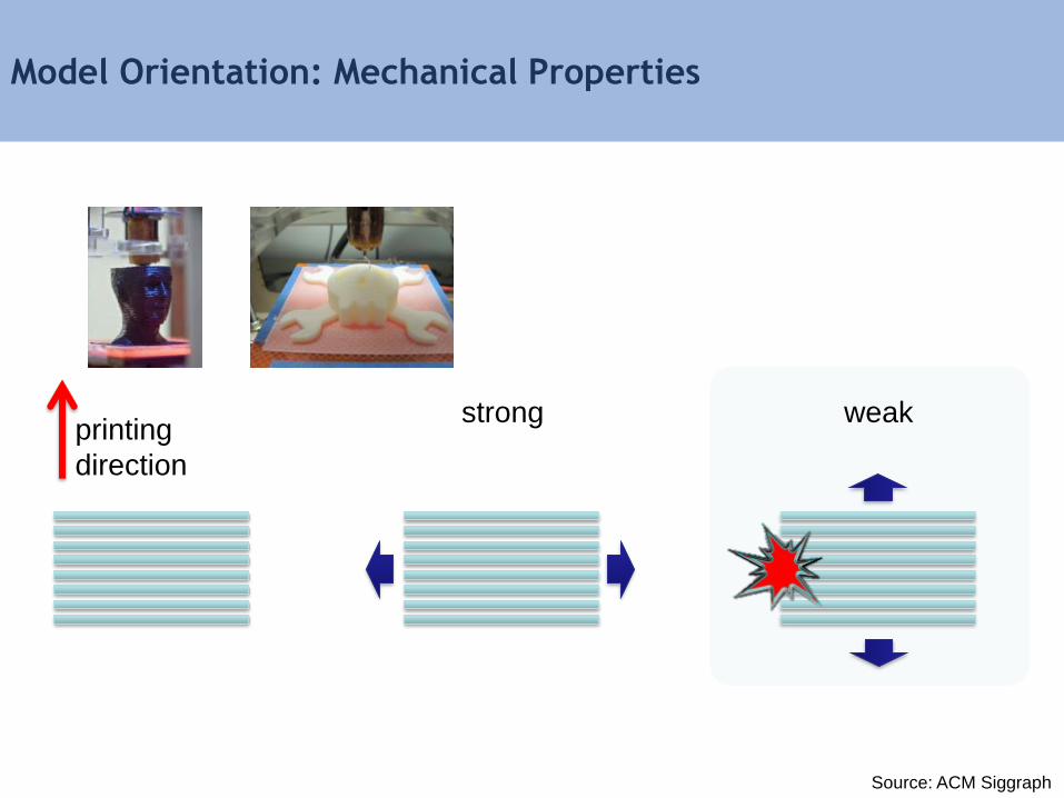
Model Orientation: Mechanical Properties
strong weakprinting
direction
Source: ACM Siggraph
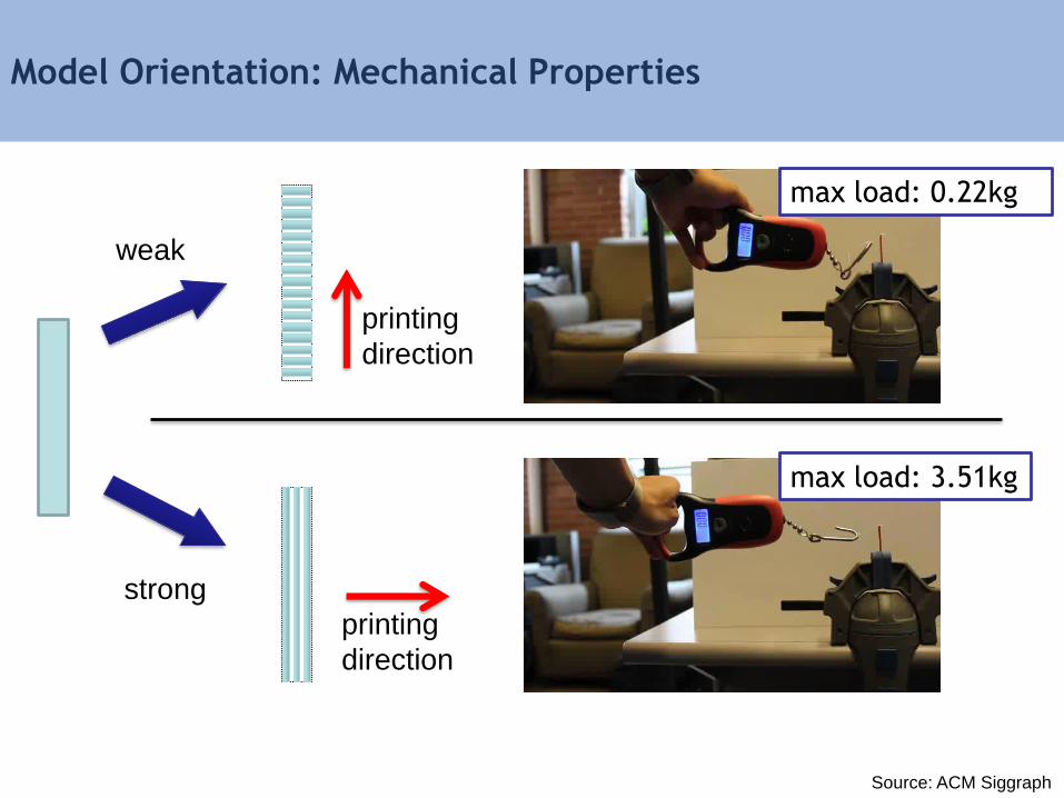
Model Orientation: Mechanical Properties
printing
direction
printing
direction
max load: 0.22kg
max load: 3.51kg
weak
strong
Source: ACM Siggraph

Model Orientation: Build Time
• Build speed is slower for the verical direction compared to the
horizontal direction
longer build time shorter build time
z
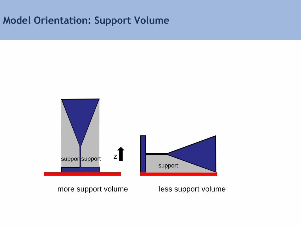
Model Orientation: Support Volume
more support volume less support volume
zsupportsupportsupport
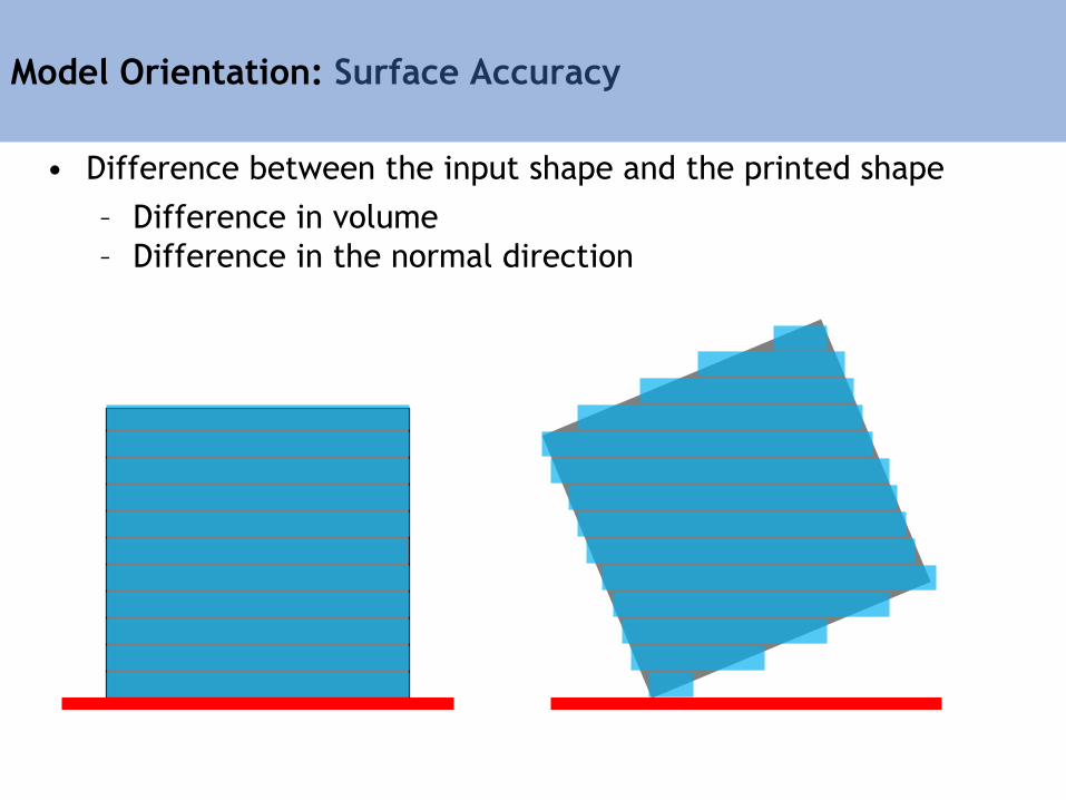
Model Orientation: Surface Accuracy
• Difference between the input shape and the printed shape
– Difference in volume
– Difference in the normal direction
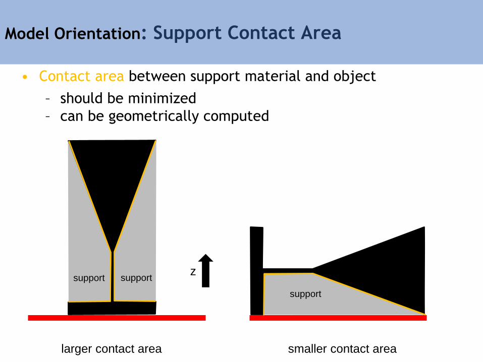
Model Orientation: Support Contact Area
larger contact area smaller contact area
z
• Contact area between support material and object
– should be minimized
– can be geometrically computed
support support
support
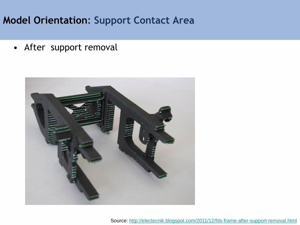
Model Orientation: Support Contact Area
• After support removal
Source: http://electecnik.blogspot.com/2011/12/fds-frame-after-support-removal.html
Algorithms for Specifying Model Orientation
• Manual placement
– User is responsible for placing parts on the build tray
• Semi-automated placement
– User places parts on the build tray
– System provides feedback on build time, support volume,
support contact area, mechanical properties
• Automated placement
– orientation is computed using optimization according to one or
more objectives (build time, support volume, support area,
mechanical properties)
3D Printing Software Pipeline
Input Model
Orientation and Positioning
Support Structures
Slicing
Path Planning
Machine Instructions
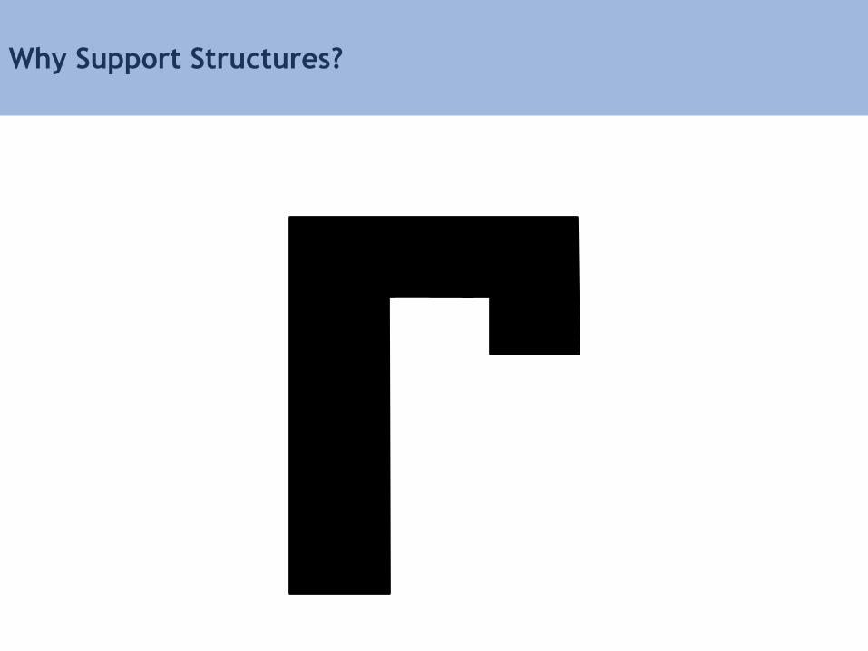
Why Support Structures?
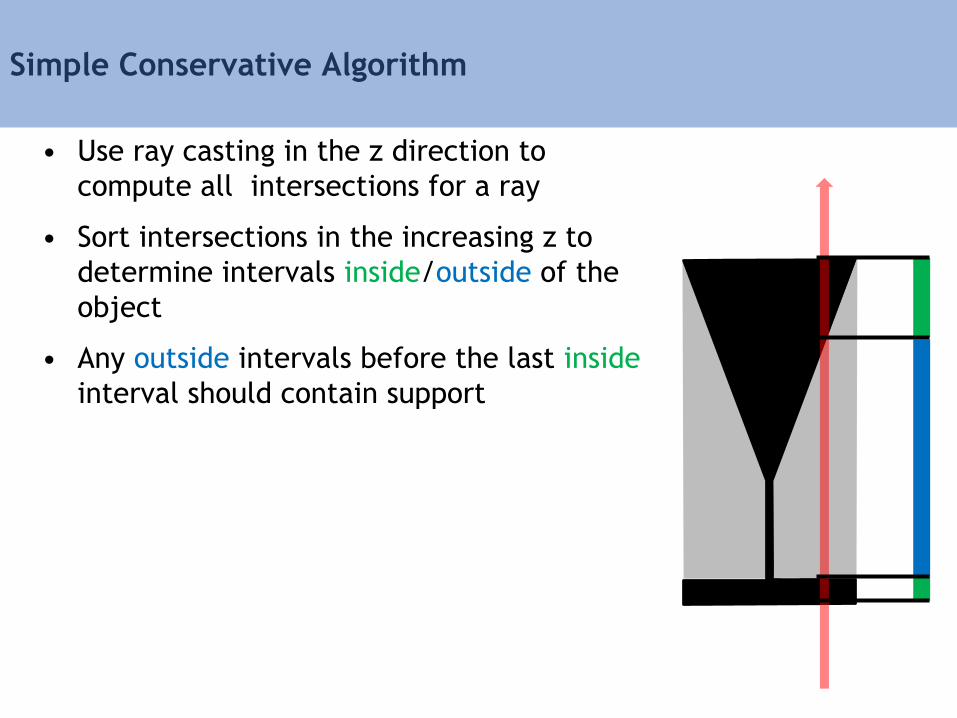
Simple Conservative Algorithm
• Use ray casting in the z direction to
compute all intersections for a ray
• Sort intersections in the increasing z to
determine intervals inside/outside of the
object
• Any outside intervals before the last inside
interval should contain support

Support Generation: Draft Angle
support
• Many printers can print at some draft angle
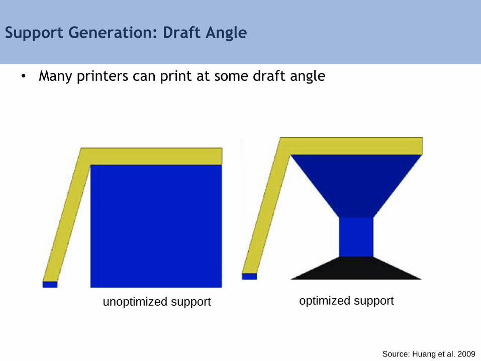
Support Generation: Draft Angle
• Many printers can print at some draft angle
Source: Huang et al. 2009
unoptimized support optimized support
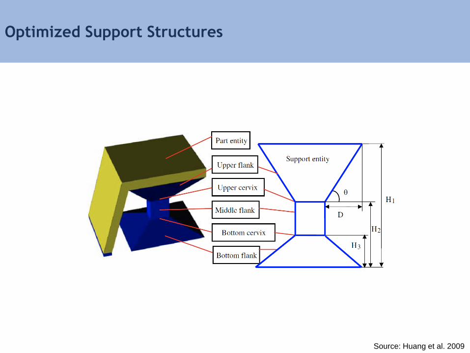
Optimized Support Structures
Source: Huang et al. 2009
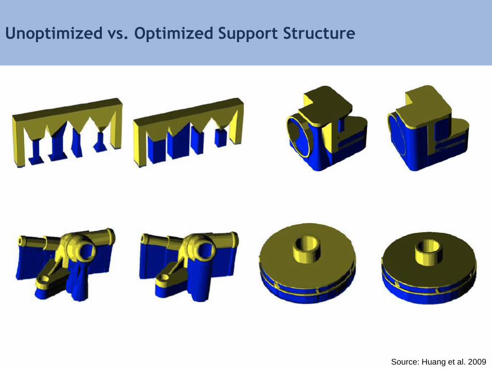
Unoptimized vs. Optimized Support Structure
Source: Huang et al. 2009
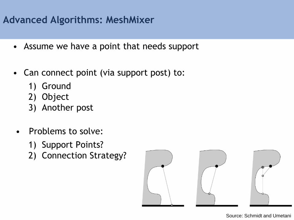
Advanced Algorithms: MeshMixer
• Assume we have a point that needs support
• Can connect point (via support post) to:
1) Ground
2) Object
3) Another post
• Problems to solve:
1) Support Points?
2) Connection Strategy?
Source: Schmidt and Umetani
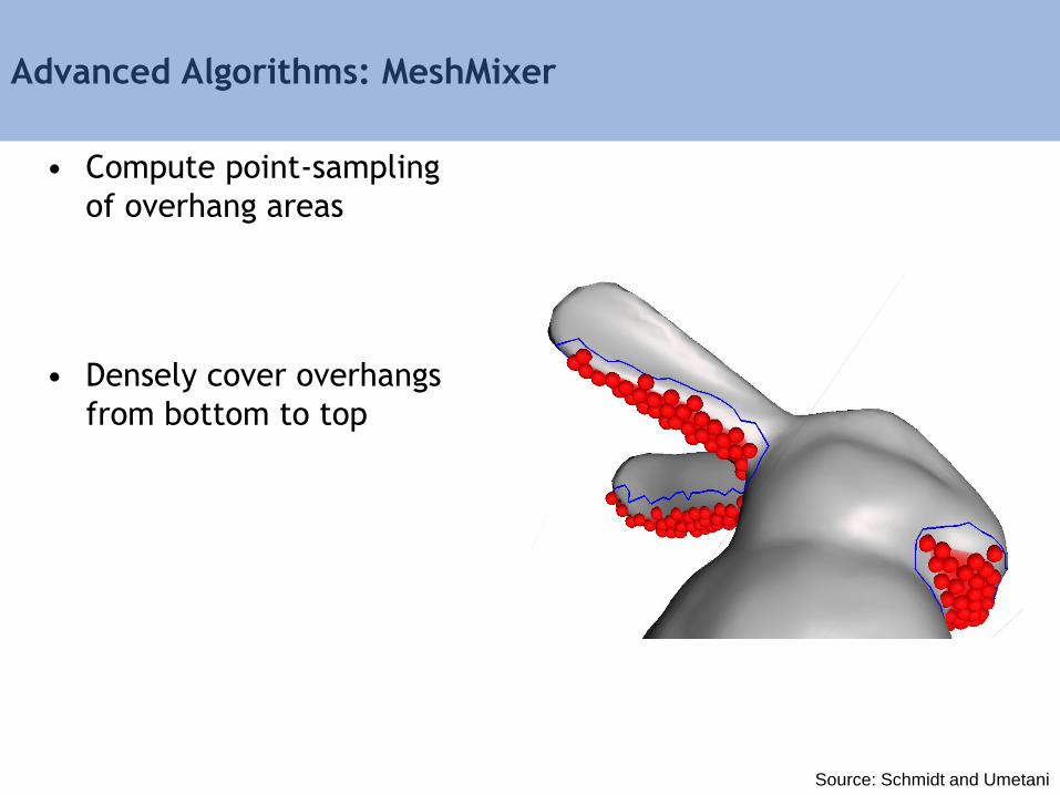
Advanced Algorithms: MeshMixer
• Compute point-sampling
of overhang areas
• Densely cover overhangs
from bottom to top
Source: Schmidt and Umetani
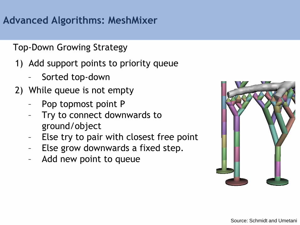
Advanced Algorithms: MeshMixer
Top-Down Growing Strategy
1) Add support points to priority queue
– Sorted top-down
2) While queue is not empty
– Pop topmost point P
– Try to connect downwards to
ground/object
– Else try to pair with closest free point
– Else grow downwards a fixed step.
– Add new point to queue
Source: Schmidt and Umetani
Advanced Algorithms: MeshMixer
Source: http://www.youtube.com/watch?v=aFTyTV3wwsE

3D Printing Software Pipeline
Input Model
Orientation and Positioning
Support Structures
Slicing
Path Planning
Machine Instructions
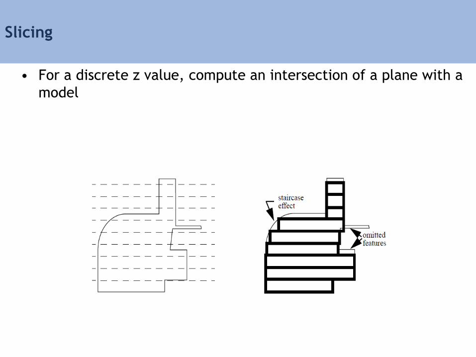
Slicing
• For a discrete z value, compute an intersection of a plane with a
model
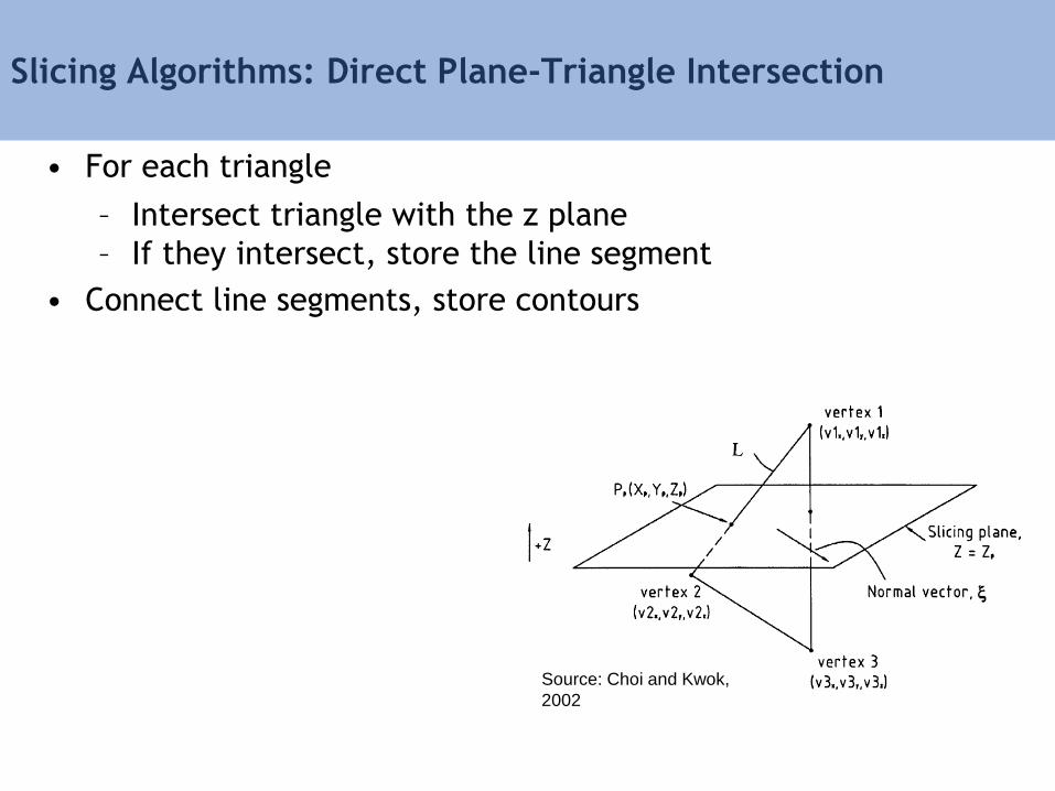
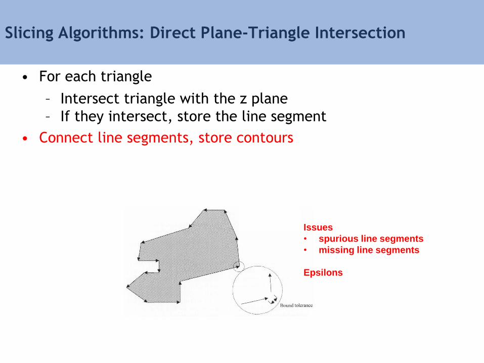
Slicing Algorithms: Direct Plane-Triangle Intersection
• For each triangle
– Intersect triangle with the z plane
– If they intersect, store the line segment
• Connect line segments, store contours
Source: Choi and Kwok,
2002

Slicing Algorithms: Direct Plane-Triangle Intersection
• For each triangle
– Intersect triangle with the z plane
– If they intersect, store the line segment
• Connect line segments, store contours
1. Intersect each edge with the plane
2. If two intersection points, connect
them to form a line segment
Source: Choi and Kwok, 2002
Slicing Algorithms: Direct Plane-Triangle Intersection
• For each triangle
– Intersect triangle with the z plane
– If they intersect, store the line segment
• Connect line segments, store contours
Issues
• spurious line segments
• missing line segments
Epsilons

Slicing Algorithms: Direct Plane-Triangle Intersection
• STL models are not always watertight -> epsilons
Source: Marsan et al, 1998

Slicing Results with Direct Plane-Triangle Intersection
Source: Choi and Kwok, 2002
3D Printing Software Pipeline
Input Model
Orientation and Positioning
Support Structures
Slicing
Path Planning
Machine Instructions

Path Planning for Vector-based 3D Printing: Contour
• Offset inwards by distance equal to the filament radius
• offset vertices
• remove self-intersections and model intersections
no offset offset inwards

Path Planning for Vector-based 3D Printing: Interior
• Tracing contours is combined with filling the interior
• The interior can be completely filled
Source: Han et al 2002
Source: Horton et al 1993
retracted hatch alternate sequencing
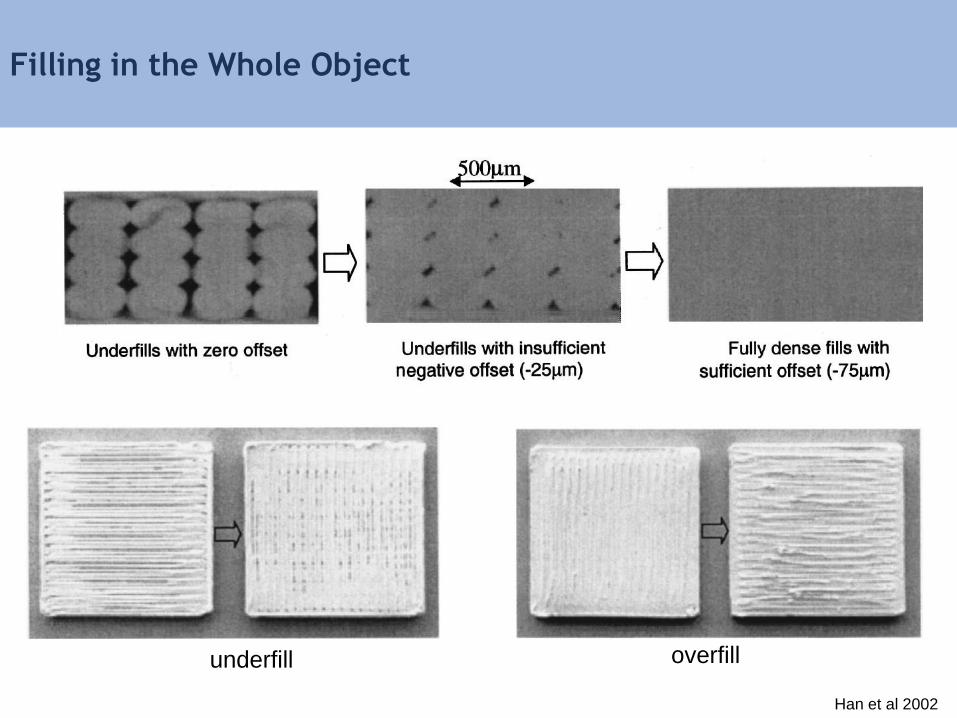
Filling in the Whole Object
underfill overfill
Han et al 2002
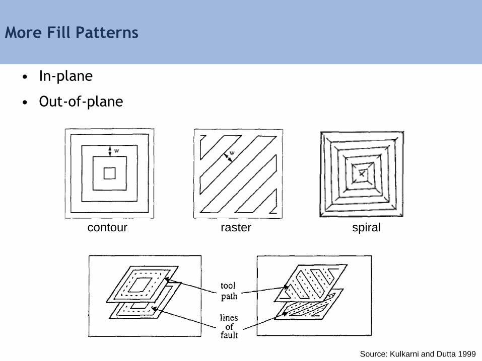
More Fill Patterns
• In-plane
• Out-of-plane
contour raster spiral
Source: Kulkarni and Dutta 1999

Equidistant Path Generation
• A set of paths are extracted based on distance to the surface
Source: Yang et al.2002
inward offset outward offset
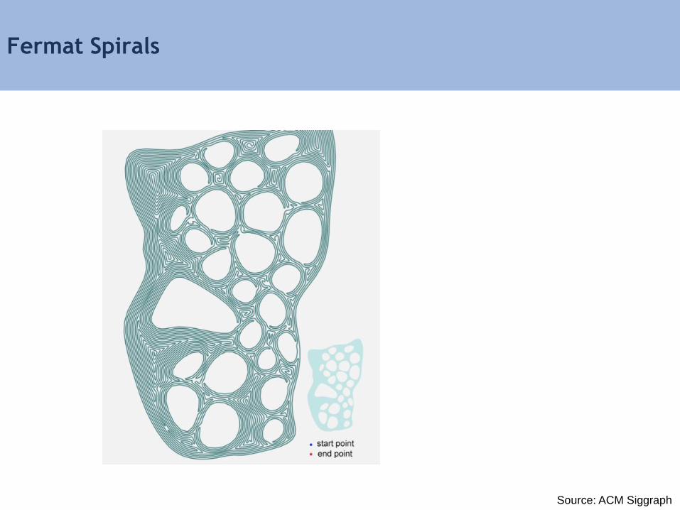
Fermat Spirals
Source: ACM Siggraph
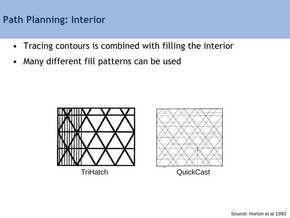
Path Planning: Interior
• Tracing contours is combined with filling the interior
• Many different fill patterns can be used
TriHatch
Source: Horton et al 1993
QuickCast
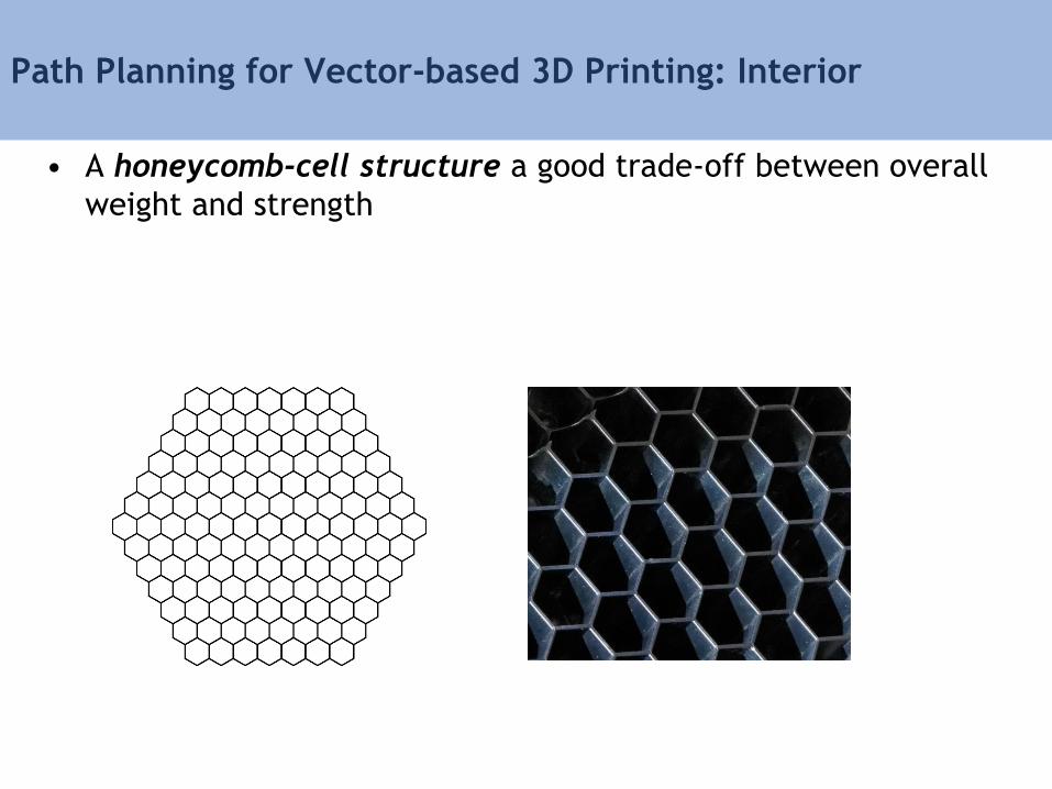
Path Planning for Vector-based 3D Printing: Interior
• A honeycomb-cell structure a good trade-off between overall
weight and strength

3D Printing Software Pipeline
Input Model
Orientation and Positioning
Support Structures
Slicing
Path Planning
Machine Instructions
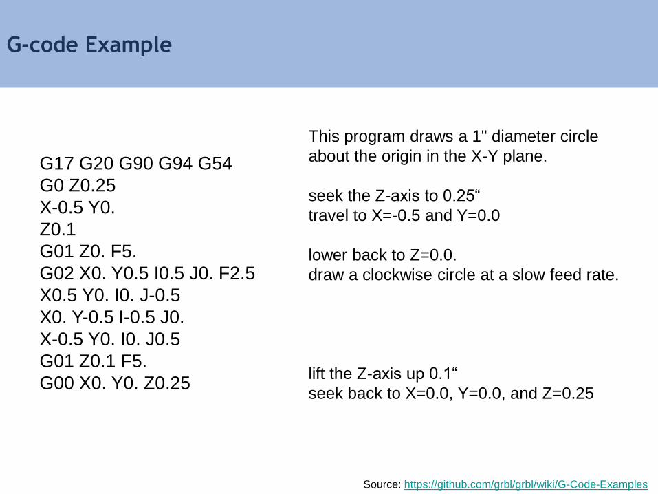
G-code Example
G17 G20 G90 G94 G54
G0 Z0.25
X-0.5 Y0.
Z0.1
G01 Z0. F5.
G02 X0. Y0.5 I0.5 J0. F2.5
X0.5 Y0. I0. J-0.5
X0. Y-0.5 I-0.5 J0.
X-0.5 Y0. I0. J0.5
G01 Z0.1 F5.
G00 X0. Y0. Z0.25
This program draws a 1" diameter circle
about the origin in the X-Y plane.
seek the Z-axis to 0.25“
travel to X=-0.5 and Y=0.0
lower back to Z=0.0.
draw a clockwise circle at a slow feed rate.
lift the Z-axis up 0.1“
seek back to X=0.0, Y=0.0, and Z=0.25
Source: https://github.com/grbl/grbl/wiki/G-Code-Examples
Course Schedule
9:00 am – 9:10 am Introduction
9:10 am – 9:25 am Hardware Review
9:25 am – 9:50 am From Design to Machine Code
9:50 am – 10:20 am Design Space Representations
10:20 am – 10:25 am Performance Driven Design
10:25 am – 10:40 am Break
10:40 am – 10:55 am Performance Space Representation
10:55 am – 11:15 am Inverse Methods
11:15 am – 11:35 am Multi-objective Inverse Methods
11:35 am – 12:00 pm Advanced Performance Driven Design
12:00 pm – 12:15 pm Course Review
Computational Design Stack
toughness
en
erg
y
toughness
Machine Code PerformanceHardware Design
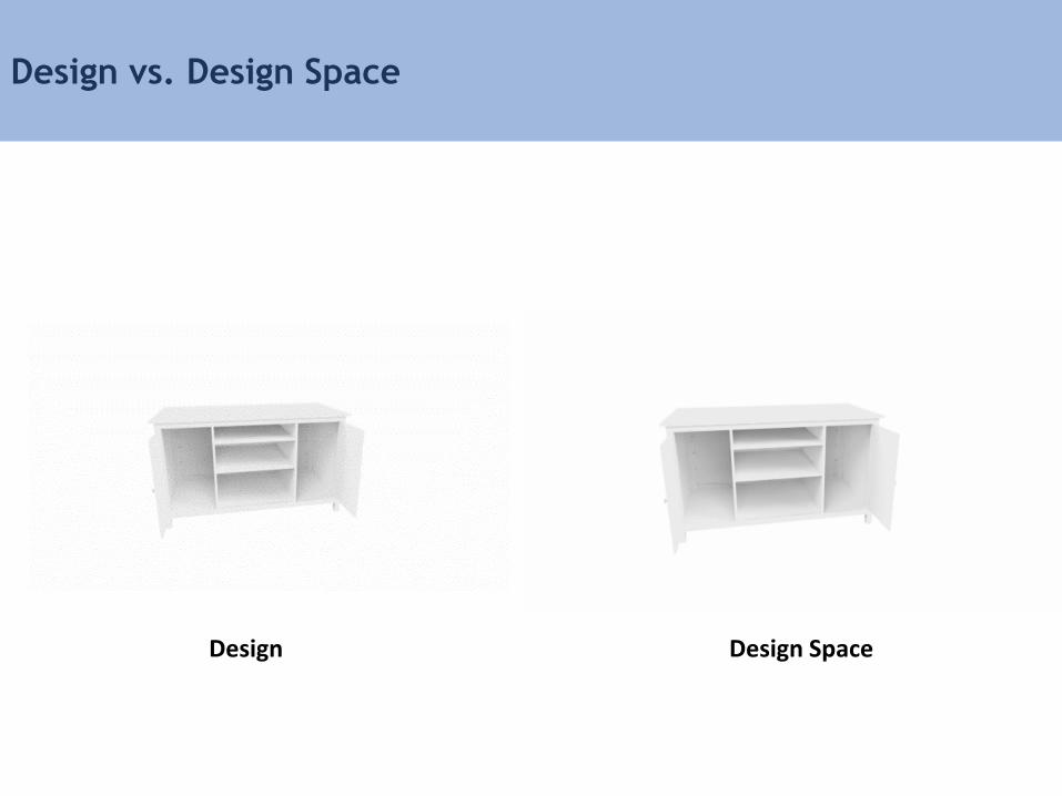
Design vs. Design Space
Design Design Space
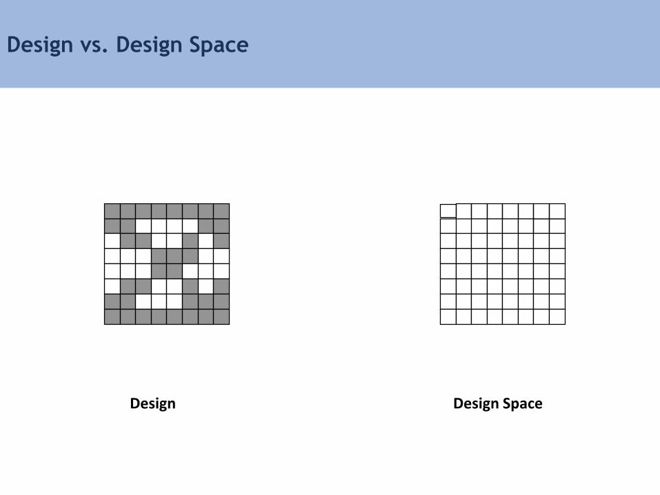
Design vs. Design Space
Design Design Space
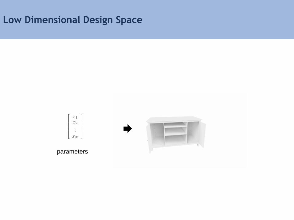
Low Dimensional Design Space
parameters

• Each design can be mathematically represented as a point in
ℝ𝐷 , where 𝐷 = number of voxels in a build volume
Design Space
Design Space
ℝ𝐷
𝒳
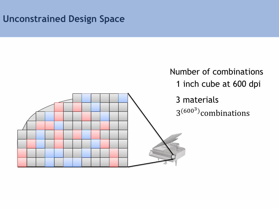
Unconstrained Design Space
Number of combinations
3(6003)combinations
1 inch cube at 600 dpi
3 materials
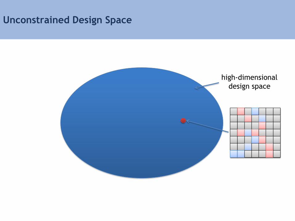
Unconstrained Design Space
high-dimensional
design space
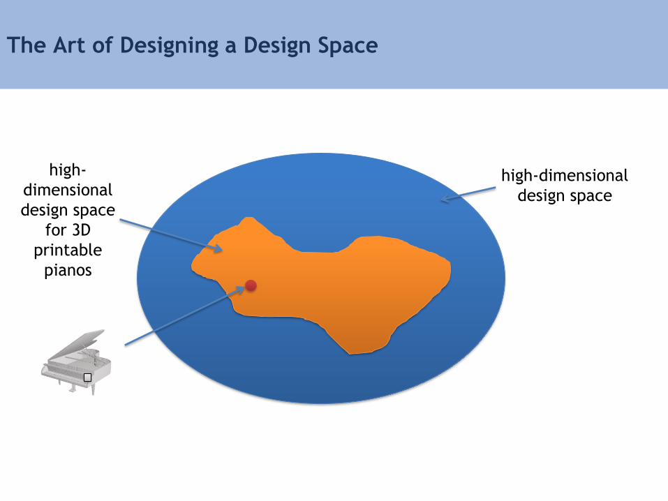
The Art of Designing a Design Space
high-dimensional
design space
high-
dimensional
design space
for 3D
printable
pianos
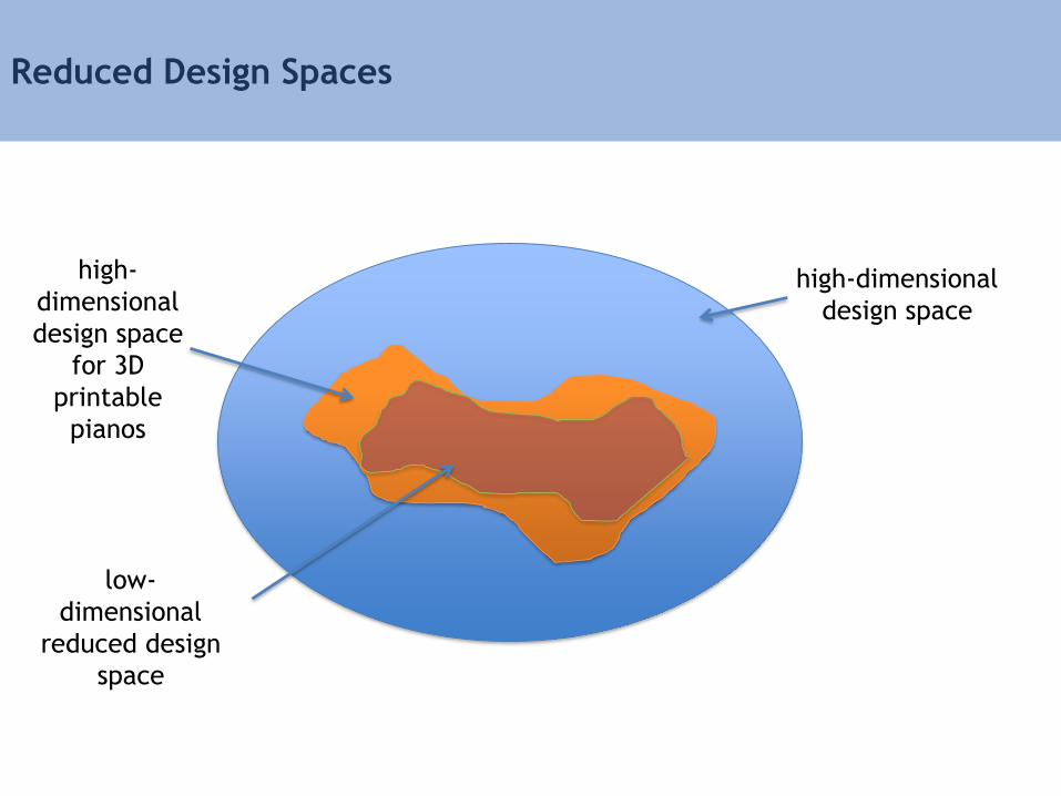
Reduced Design Spaces
high-dimensional
design space
high-
dimensional
design space
for 3D
printable
pianos
low-
dimensional
reduced design
space
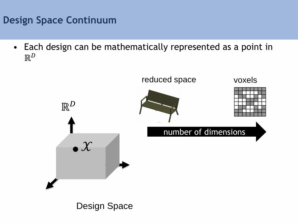
• Each design can be mathematically represented as a point in
ℝ𝐷
Design Space
Design Space Continuum
ℝ𝐷
𝒳number of dimensions
reduced space voxels
Methods for Designing Reduced Design Spaces
• Parametric modeling
• Procedural modeling
• Deformation methods
Methods for Designing Reduced Design Spaces
• Parametric modeling
• Procedural modeling
• Deformation methods
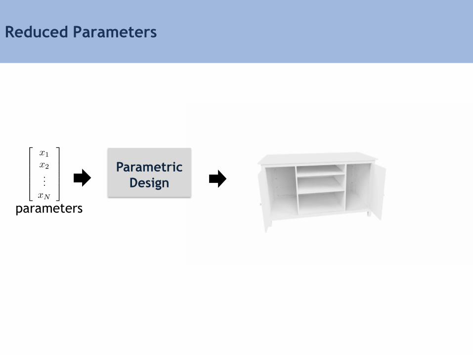
Reduced Parameters
parameters
Parametric
Design
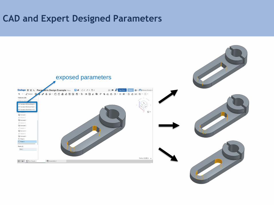
CAD and Expert Designed Parameters
exposed parameters
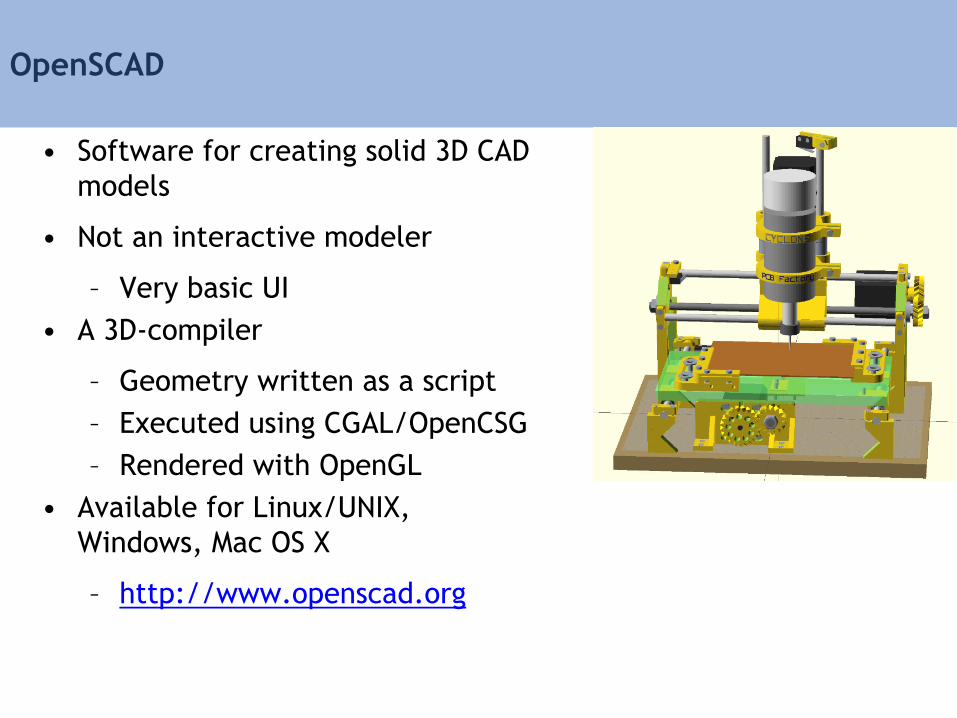
OpenSCAD
• Software for creating solid 3D CAD
models
• Not an interactive modeler
– Very basic UI
• A 3D-compiler
– Geometry written as a script
– Executed using CGAL/OpenCSG
– Rendered with OpenGL
• Available for Linux/UNIX,
Windows, Mac OS X
– http://www.openscad.org
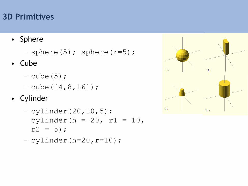
3D Primitives
• Sphere
– sphere(5); sphere(r=5);
• Cube
– cube(5);
– cube([4,8,16]);
• Cylinder
– cylinder(20,10,5);
cylinder(h = 20, r1 = 10,
r2 = 5);
– cylinder(h=20,r=10);
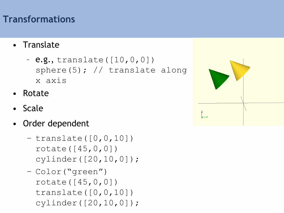
Transformations
• Translate
– e.g., translate([10,0,0])
sphere(5); // translate along
x axis
• Rotate
• Scale
• Order dependent
– translate([0,0,10])
rotate([45,0,0])
cylinder([20,10,0]);
– Color(“green”)
rotate([45,0,0])
translate([0,0,10])
cylinder([20,10,0]);
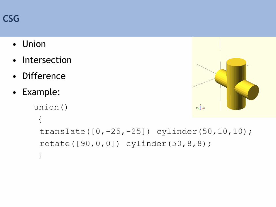
CSG
• Union
• Intersection
• Difference
• Example:
union()
{
translate([0,-25,-25]) cylinder(50,10,10);
rotate([90,0,0]) cylinder(50,8,8);
}
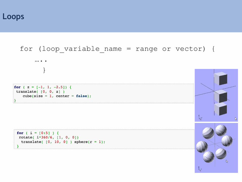
Loops
for (loop_variable_name = range or vector) {
…..
}

Module
• Procedures/Functions
module leaves() { cylinder(20,5,0); }
module box() { cube([5,10,15]); }
module tree() {
leaves();
scale([0.5,0.5,0.5]) translate([-2.5,-5,-15]) box();
}
tree();

Module
• Parameters
module box(w,l,h,tx,ty,tz)
{
translate([tx,ty,tz])
cube([w,l,h]);
}
box(5,10,15,10,0,5);
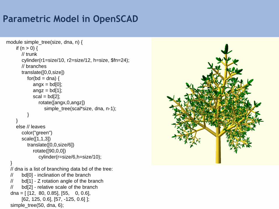
Parametric Model in OpenSCAD
module simple_tree(size, dna, n) {
if (n > 0) {
// trunk
cylinder(r1=size/10, r2=size/12, h=size, $fn=24);
// branches
translate([0,0,size])
for(bd = dna) {
angx = bd[0];
angz = bd[1];
scal = bd[2];
rotate([angx,0,angz])
simple_tree(scal*size, dna, n-1);
}
}
else // leaves
color("green")
scale([1,1,3])
translate([0,0,size/6])
rotate([90,0,0])
cylinder(r=size/6,h=size/10);
}
// dna is a list of branching data bd of the tree:
// bd[0] - inclination of the branch
// bd[1] - Z rotation angle of the branch
// bd[2] - relative scale of the branch
dna = [ [12, 80, 0.85], [55, 0, 0.6],
[62, 125, 0.6], [57, -125, 0.6] ];
simple_tree(50, dna, 6);
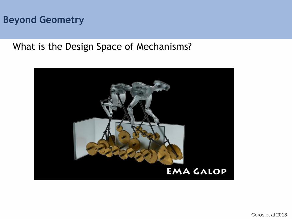
Beyond Geometry
What is the Design Space of Mechanisms?
Coros et al 2013
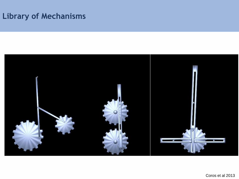
Library of Mechanisms
Coros et al 2013
Methods for Designing Reduced Design Spaces
• Parametric modeling
• Procedural modeling
• Deformation methods

Formal Grammars and Languages
• A finite set of nonterminal symbols: {S, A, B}
• A finite set of terminal symbols: {a, b}
• A finite set of production rules: S → AB
• A start symbol: S
• Generates a set of finite-length sequences of symbols by
recursively applying production rules starting with S
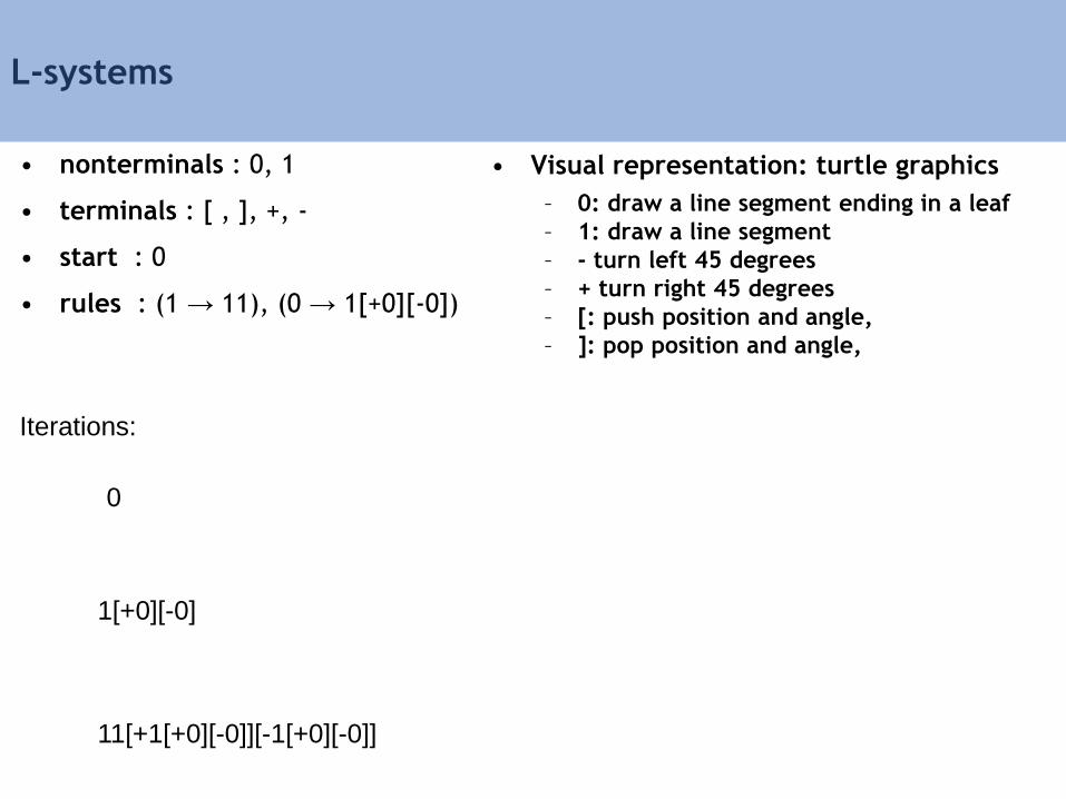
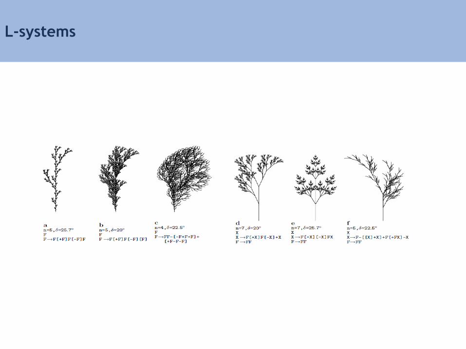
L-systems
• nonterminals : 0, 1
• terminals : [ , ], +, -
• start : 0
• rules : (1 → 11), (0 → 1[+0][-0])
0
• Visual representation: turtle graphics
– 0: draw a line segment ending in a leaf
– 1: draw a line segment
– - turn left 45 degrees
– + turn right 45 degrees
– [: push position and angle,
– ]: pop position and angle,
1[+0][-0]
11[+1[+0][-0]][-1[+0][-0]]
Iterations:

L-systems
• nonterminals : 0, 1
• terminals : [ , ], +, -
• start : 0
• rules : (1 → 11), (0 → 1[+0][-0])
n = 0
• Visual representation: turtle graphics
– 0: draw a line segment ending in a leaf
– 1: draw a line segment
– - turn left 45 degrees
– + turn right 45 degrees
– [: push position and angle,
– ]: pop position and angle,
n = 1 : 1[+0][-0] n = 2 : 11[+1[+0][-0]][-1[+0][-0]]
L-systems
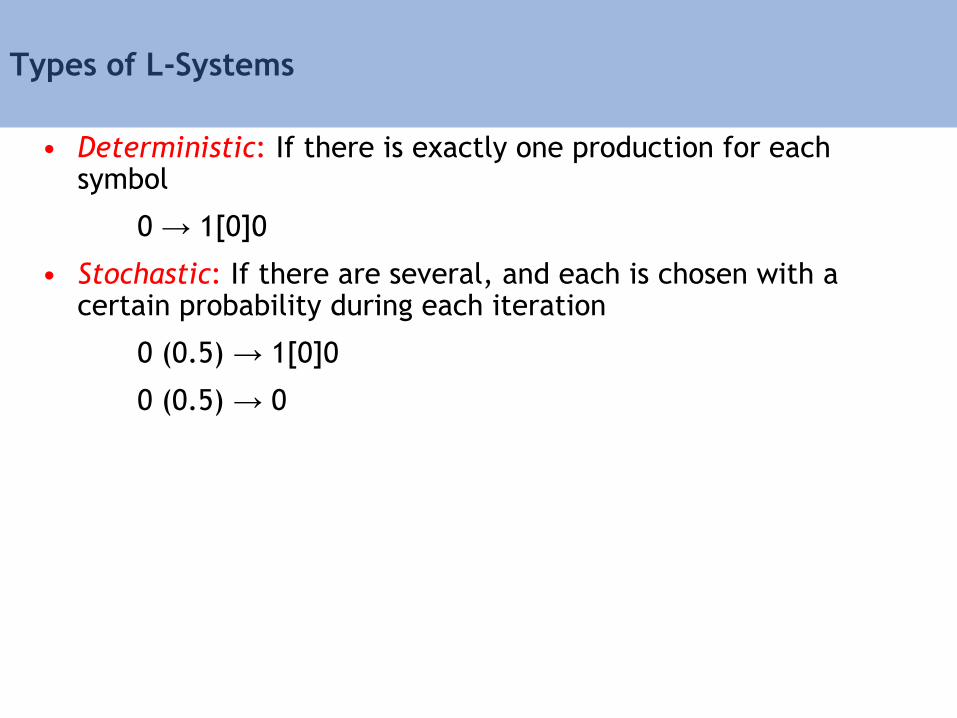
Types of L-Systems
• Deterministic: If there is exactly one production for each symbol
0 → 1[0]0
• Stochastic: If there are several, and each is chosen with a certain probability during each iteration
0 (0.5) → 1[0]0
0 (0.5) → 0
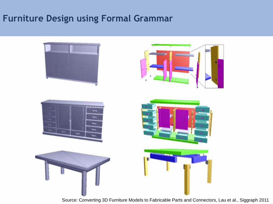
Furniture Design using Formal Grammar
Source: Converting 3D Furniture Models to Fabricable Parts and Connectors, Lau et al., Siggraph 2011

: Set of Production Rules
The language specifies a directed graph,
and each graph represents parts and connectors
Non-terminal
Symbols
- Collection of Parts
Terminal Symbols
- Separate Parts
: Start Symbol
Formal Grammar for 2D Cabinets
Source: Converting 3D Furniture Models to Fabricable Parts and Connectors, Lau et al., Siggraph 2011
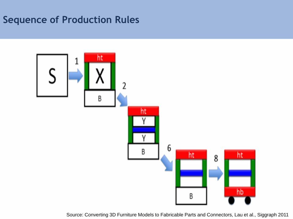
Sequence of Production Rules
Source: Converting 3D Furniture Models to Fabricable Parts and Connectors, Lau et al., Siggraph 2011
Methods for Designing Reduced Design Spaces
• Parametric modeling
• Procedural modeling
• Deformation methods
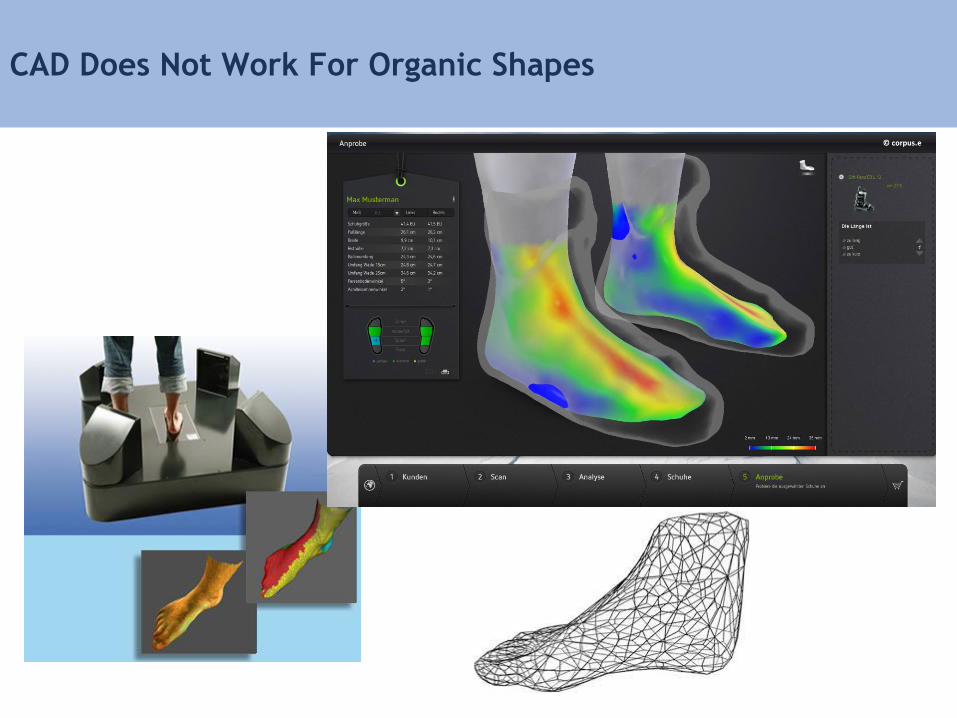
CAD Does Not Work For Organic Shapes
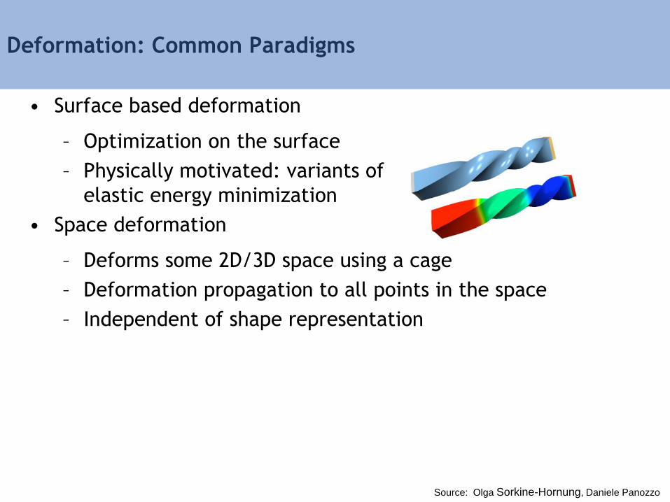
Deformation: Common Paradigms
• Surface based deformation
– Optimization on the surface
– Physically motivated: variants of
elastic energy minimization
• Space deformation
– Deforms some 2D/3D space using a cage
– Deformation propagation to all points in the space
– Independent of shape representation
Source: Olga Sorkine-Hornung, Daniele Panozzo
Geometric Deformation Models
• Surface-Based Deformations
– Laplacian Mesh Deformation
– As Rigid As Possible Deformation (ARAP)
• Space-Based Deformations
– Cages
– Linear Blend Skinning (LBS)
– Bounded Biharmonic Weights
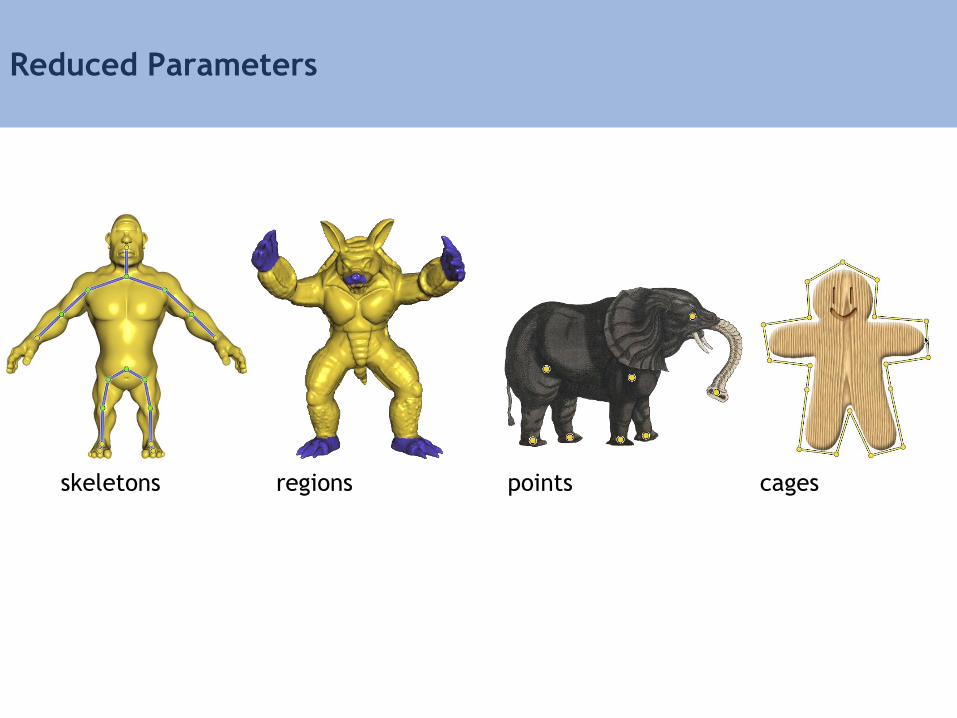
skeletons regions points cages
Reduced Parameters
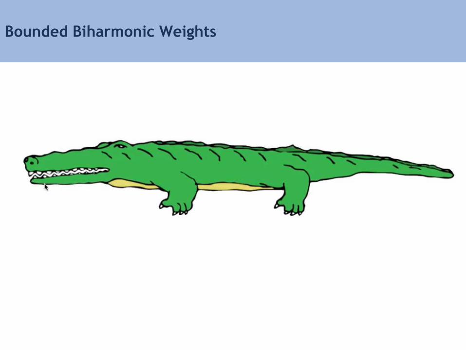
Bounded Biharmonic Weights
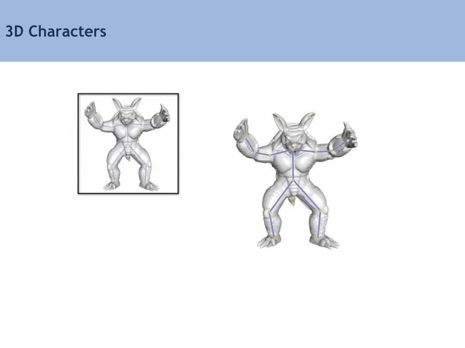
3D Characters
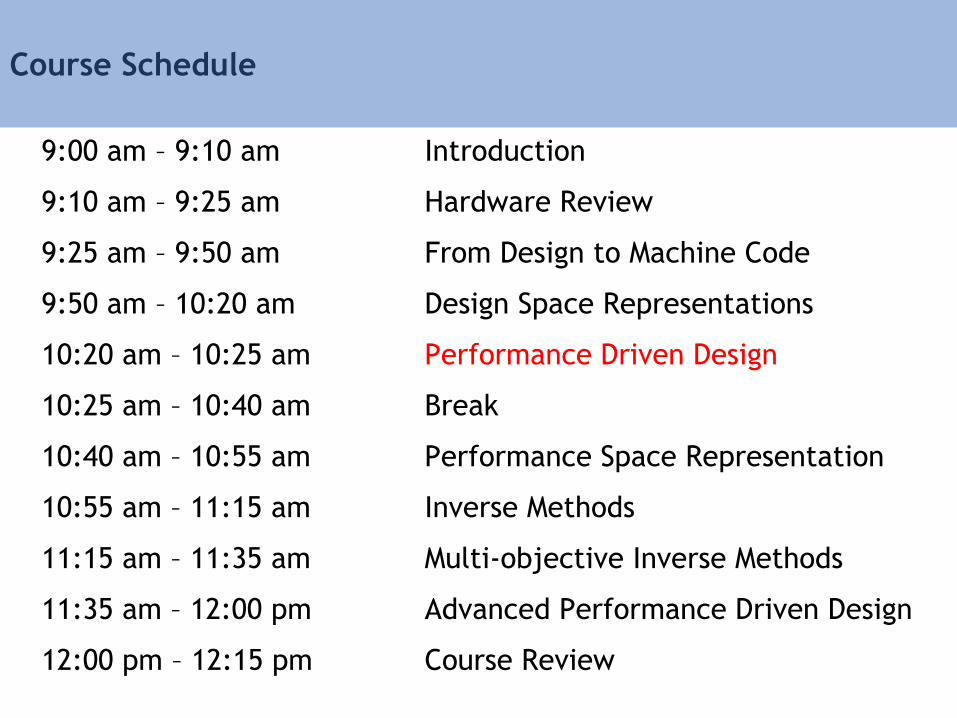
Course Schedule
9:00 am – 9:10 am Introduction
9:10 am – 9:25 am Hardware Review
9:25 am – 9:50 am From Design to Machine Code
9:50 am – 10:20 am Design Space Representations
10:20 am – 10:25 am Performance Driven Design
10:25 am – 10:40 am Break
10:40 am – 10:55 am Performance Space Representation
10:55 am – 11:15 am Inverse Methods
11:15 am – 11:35 am Multi-objective Inverse Methods
11:35 am – 12:00 pm Advanced Performance Driven Design
12:00 pm – 12:15 pm Course Review
Computational Design Stack
toughness
en
erg
y
Machine Code PerformanceHardware Design

Design Driven By Performance
Design Space Performance Space
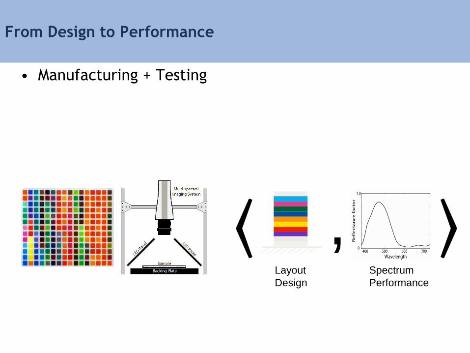
From Design to Performance
• Manufacturing + Testing
⟨ , ⟩Layout
Design
Spectrum
Performance
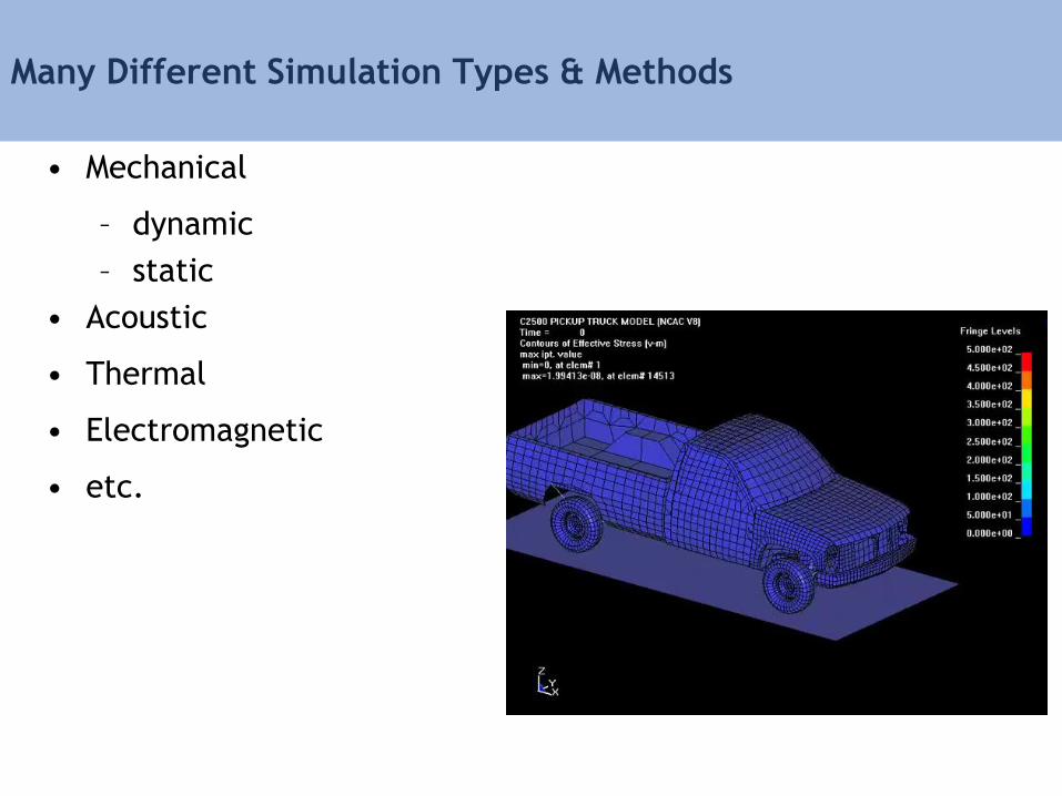
Many Different Simulation Types & Methods
• Mechanical
– dynamic
– static
• Acoustic
• Thermal
• Electromagnetic
• etc.
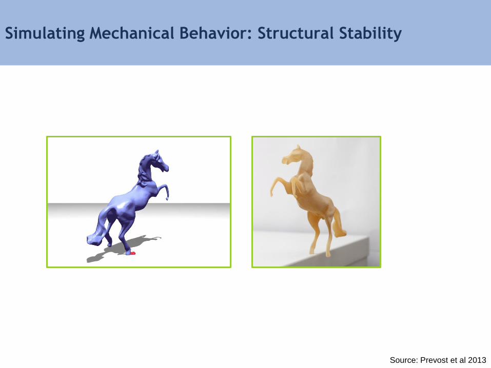
Simulating Mechanical Behavior: Structural Stability
Source: Prevost et al 2013
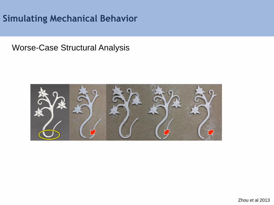
Simulating Mechanical Behavior
Worse-Case Structural Analysis
Zhou et al 2013
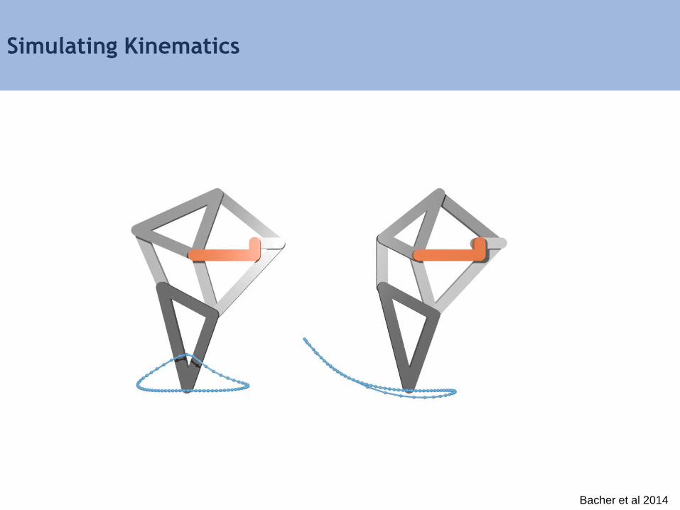
Simulating Kinematics
Bacher et al 2014
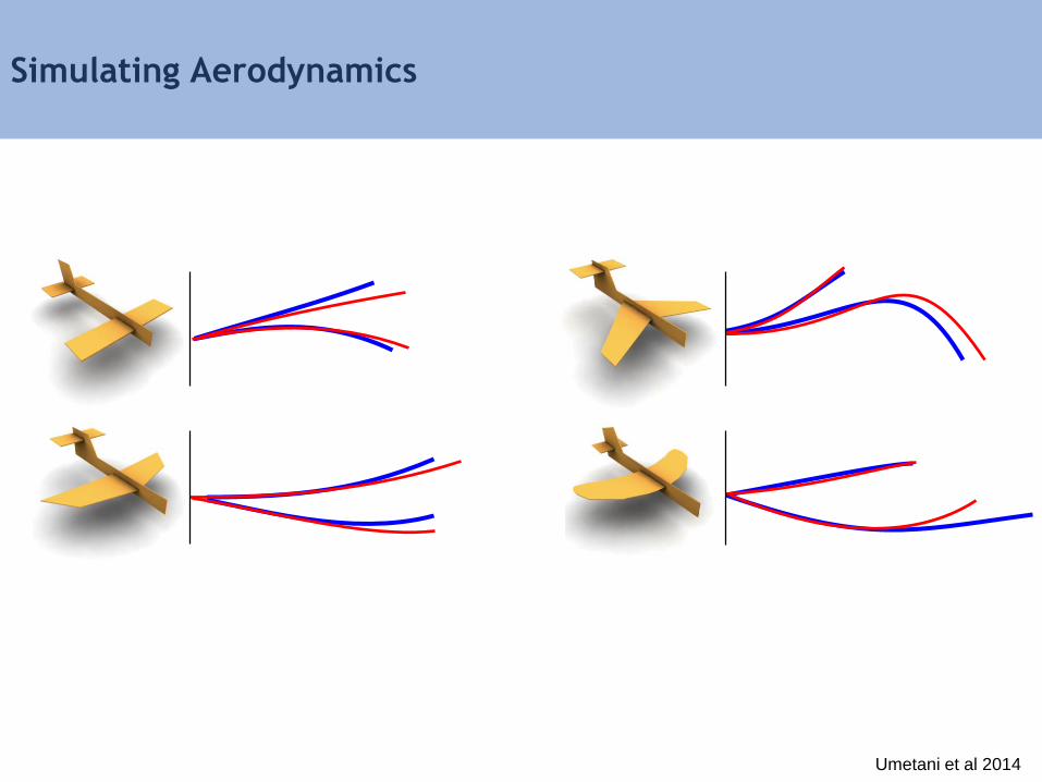
Simulating Aerodynamics
Umetani et al 2014

Course Schedule
9:00 am – 9:10 am Introduction
9:10 am – 9:25 am Hardware Review
9:25 am – 9:50 am From Design to Machine Code
9:50 am – 10:20 am Design Space Representations
10:20 am – 10:25 am Performance Driven Design
10:25 am – 10:40 am Break
10:40 am – 10:55 am Performance Space Representation
10:55 am – 11:15 am Inverse Methods
11:15 am – 11:35 am Multi-objective Inverse Methods
11:35 am – 12:00 pm Advanced Performance Driven Design
12:00 pm – 12:15 pm Course Review