computational analysis & design for composites€¦ · panel using the fe software hyperworks...
TRANSCRIPT

www.welshcomposites.co.uk
Computational Analysis & Design for Composites
Prof. Johann Sienz & Dr. Mariela Luege
Swansea University

www.welshcomposites.co.uk
OUTLINE
2
Case studiesStringer design and rib design
Steps in the numerical analysis of composite structures
Composite laminates definition and design
Stress strain relations for composite materials from macroscopic and microscopic approaches
Effective properties for isotropic, orthotropic and anisotropic materials and overview of mixture and homogenization approaches
Laminates damage, failure criteria and buckling
Numerical simulation of a composite stiffened panel using the FE software HYPERWORKS
Preparation of input file and analysis of results
33 Hat stiffened panel
www.welshcomposites.co.uk
OUTLINE
3
Case studiesStringer design and rib design
Steps in the numerical analysis of composite structures
Composite laminates definition and design
Stress strain relations for composite materials from macroscopic and microscopic approaches
Effective properties for isotropic, orthotropic and anisotropic materials and overview of mixture and homogenization approaches
Laminates damage, failure criteria and buckling
Numerical simulation of a composite stiffened panel using the finite element software HYPERWORKS
Preparation of input file and analysis of results
33 Hat stiffened panel

4
Underside ofSkin Panel
Stringers
Skin Panel
Rear Spar
Centre SparFront SparRibs
Horizontal Stiffener
Skin
Vertical Stiffener
Packer
Stringer X-Section
Case studies: Thin & thick composite stringer design
courtesy

5
Case studies: Stringer X-section design
55
Initial Superply
layup
Traditional Best Design
Shuffled Optimized
Design
Mass = 4.73kgBuckling = 1.18
Mass = 11.64kgBuckling = 3.14
Mass = 4.66kgBuckling = 1.03
Skin
Vertical Stiffener
Horizontal Stiffener
Packer UD 0º
45º-45º90º
courtesy
5

6
Geometry Extraction
Initial design Topology OptimizationMaterial Layout
Size and Shape OptimizationBuckling and Stress
~ 10%
~ 35%
courtesy
Case studies: Leading edge droop nose rib design
Final design

7
DYNAMIC ANALYSIS
courtesy

www.welshcomposites.co.uk
OUTLINE
8
Case studiesStringer design, rib design and some crush analysis
Steps for the numerical analysis of composite structures
Composite laminates definition and design
Stress strain relations for composite materials from macroscopic and microscopic approaches
Effective properties for isotropic, orthotropic and anisotropic materials and overview of mixture and homogenization approaches
Laminates damage, failure criteria and buckling
Numerical simulation of a composite stiffened panel using the FE software HYPERWORKS
Preparation of input file and analysis of results

www.welshcomposites.co.uk
Overview - Example
What do we know:We have a plateWe know how it is supportedWe know what composite material it is made ofWe know what the loading is
What would we like to know?
DisplacementsStrainsStressesDelaminationBucklingFracture
9
www.welshcomposites.co.uk
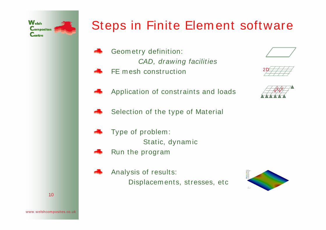
Steps in Finite Element software
Geometry definition: CAD, drawing facilities
FE mesh construction
Application of constraints and loads
Selection of the type of Material
Type of problem:Static, dynamic
Run the program
Analysis of results: Displacements, stresses, etc
10
2D

www.welshcomposites.co.uk
Computer-Aided Engineering (CAE) tools
Available computer-aided engineering (CAE) tools commonly used in the industry :
ABAQUS, ALTAIR HYPERWORKS, ANSYS and NASTRAN
Common characteristics:
FE solvers for solids, fluids, thermal, acoustic, electromagnetic and/or multiphysics problems
Robust and reliable meshing tools
Several optimization methods:
topological, size and shape
Combination of performance data management, process automation and good data exchange facilities for the solution of large scale optimization problems11

www.welshcomposites.co.uk
OUTLINE
12
The topics that are covered include:
Case studiesStringer design, rib design and some crush analysis
Steps in the numerical analysis of composite structures
Composite laminates definition and design
Stress strain relations for composite materials from macroscopic and microscopic approaches
Effective properties for isotropic, orthotropic and anisotropic materials and overview of mixture and homogenization approaches
Laminates damage, failure criteria and buckling
Numerical simulation of a composite stiffened panel using the FE software HYPERWORKS
Preparation of input file and analysis of results

www.welshcomposites.co.uk
Material definition:Composite laminate
A fibre composite laminate consists of thin, parallel, unidirectional reinforced layers, which are firmly bounded together
Each layer (called also lamina) is usually represented as an homogeneous orthotropic material
Composite Laminates are typically defined using:
nr of layers, nr of layers,
thickness, thickness,
fibre orientation, fibre orientation,
layer materiallayer material
13
www.welshcomposites.co.uk
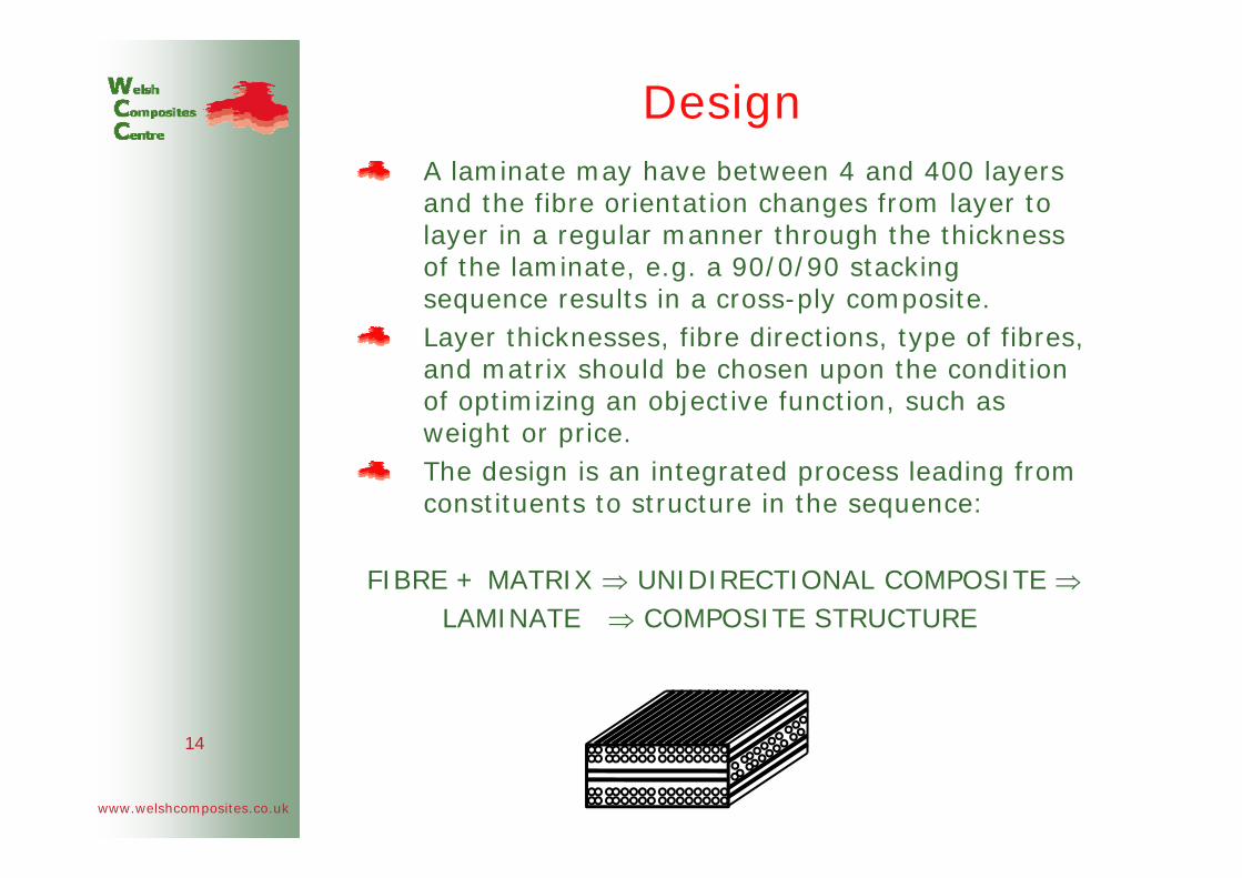
DesignA laminate may have between 4 and 400 layers and the fibre orientation changes from layer to layer in a regular manner through the thickness of the laminate, e.g. a 90/0/90 stacking sequence results in a cross-ply composite.Layer thicknesses, fibre directions, type of fibres, and matrix should be chosen upon the condition of optimizing an objective function, such as weight or price.The design is an integrated process leading from constituents to structure in the sequence:
FIBRE + MATRIX ⇒ UNIDIRECTIONAL COMPOSITE ⇒LAMINATE ⇒ COMPOSITE STRUCTURE
14

www.welshcomposites.co.uk
Macro- vs. Micro-mechanicsMacromechanic analysis: Macromechanic analysis: no direct account of the fact that one is dealing with a composite material; one merely acknowledges this by modelling the material behaviour as isotropic, orthotropic or anisotropic with the material model properties obtained experimentally.
Micromechanic analysis: Micromechanic analysis: the behavior of the composite is directly predicted from the knowledge of the properties of the constituents (fiber, matrix) by using mathematical tools, such as:
Mixture theoryHomogenization theory
Studying performance on a micro-scale is essential if one needs to understand fully what controls the stiffness and strength of the composites15

www.welshcomposites.co.uk
Stress analysisIf the thickness of the laminate is generally small compared to the planar dimensions
⇒ two dimensional analyses are used
Assumption concerning the variation of displacements and/or stress through the thickness of the laminate:
Classical plate theoryFirst-order shear deformation theory
Further assumptions:
Layers are perfectly bounded togetherThe material of each layer is linearly elastic and orthotropicEach layer is of uniform thicknessThe strains are small 16

www.welshcomposites.co.uk
OUTLINE
17
The topics that are covered include:
Case studiesStringer design, rib design and some crush analysis
Steps in the numerical analysis of composite structures
Composite laminates definition and design
Stress strain relations for composite materials from macroscopic and microscopic approaches
Effective properties for isotropic, orthotropic and anisotropic materials and overview of mixture and homogenization approaches
Laminates damage, failure criteria and buckling
Numerical simulation of a composite stiffened panel using the FE software HYPERWORKS
Preparation of input file and analysis of results

www.welshcomposites.co.uk
Effective material propertiesEffective material properties define the relation between averages of field variables, such as stresses and strains, when their space variation is statistically homogeneous
σ11, σ22, σ33 : normal stressesσ12, σ13, σ23 : shear stresses ε11, ε22, ε33 : normal strainsε12, ε13, ε23 : shear strains
D: effective elastic coefficient reflecting material symmetry
18
www.welshcomposites.co.uk
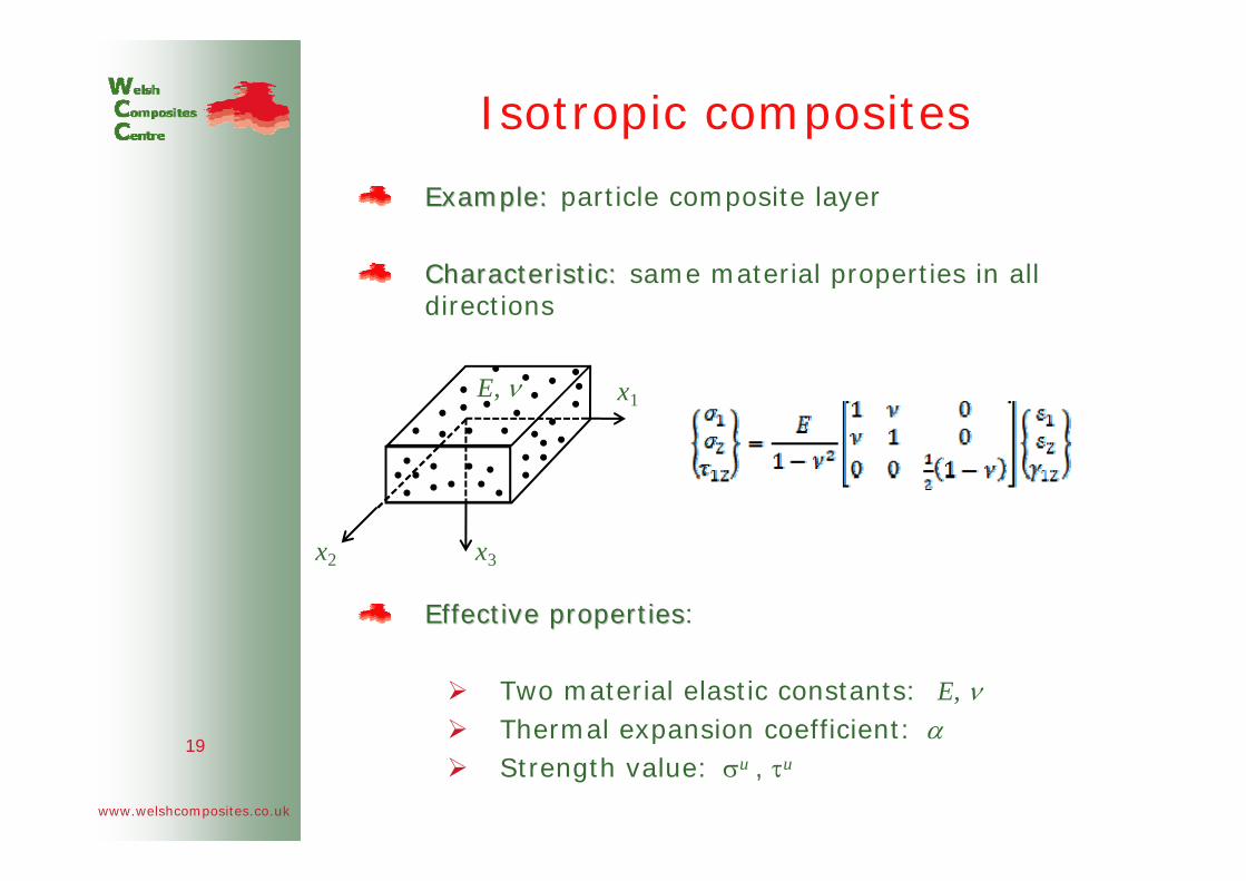
Isotropic composites
Example: Example: particle composite layer
Characteristic: Characteristic: same material properties in all directions
Effective propertiesEffective properties:
Two material elastic constants: E, ν Thermal expansion coefficient: αStrength value: σu , τu
19
E, ν
x2 x3
x1

www.welshcomposites.co.uk
Orthotropic composites
ExampleExample: unidirectional fibre composite layer
⇒ The fibres are oriented in two mutually perpendicular directions
Effective properties Effective properties (plane stress):Four material elastic constants: E1, E2, G12 , ν12
Thermal expansion coefficient: α1, α2
Strength value: σu1, σu
2, τu12
20
x2 x3
x1
www.welshcomposites.co.uk
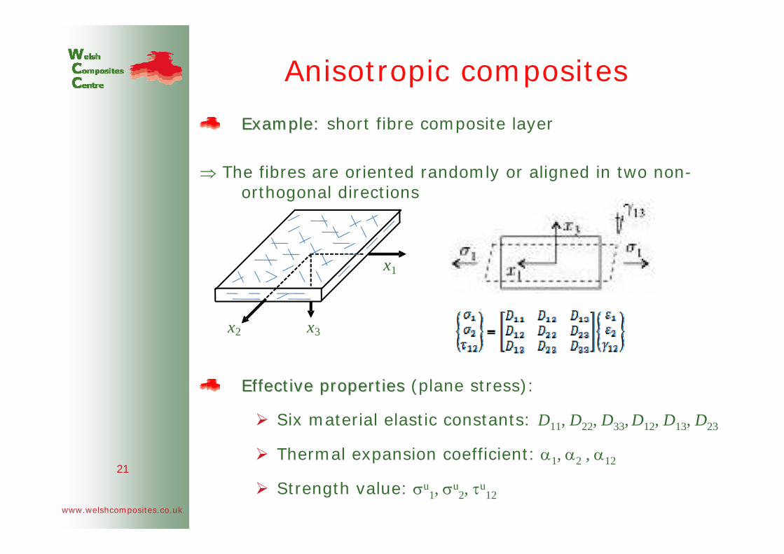
Anisotropic composites
Example: Example: short fibre composite layer
⇒ The fibres are oriented randomly or aligned in two non-orthogonal directions
Effective properties Effective properties (plane stress):
Six material elastic constants: D11, D22, D33, D12, D13, D23
Thermal expansion coefficient: α1, α2 , α12
Strength value: σu1, σu
2, τu12
21
x2 x3
x1

Mixture approachNotion of representative volume element (RVE):
RVE main properties:1.Its structure is ‘entirely typical’ for the composite
2.It contains a ‘sufficient number’ of micro-structural elements so that boundary conditions at the surface of the composite do not affect its
effective properties
Model
t
≡
1=Vf + Vm
t
Vf , Vm : fibre and matrix volume fraction
Simplified model
t
Representative Volume Element (RVE)
22

RVE Longitudinal
Evaluation of the effective stiffness
≡
Transversal
≡
matrix fibre
fibre matrix
Ef
Em ε
P
EfEm P
ε=εm+εf
RVE Transverse
23
www.welshcomposites.co.uk
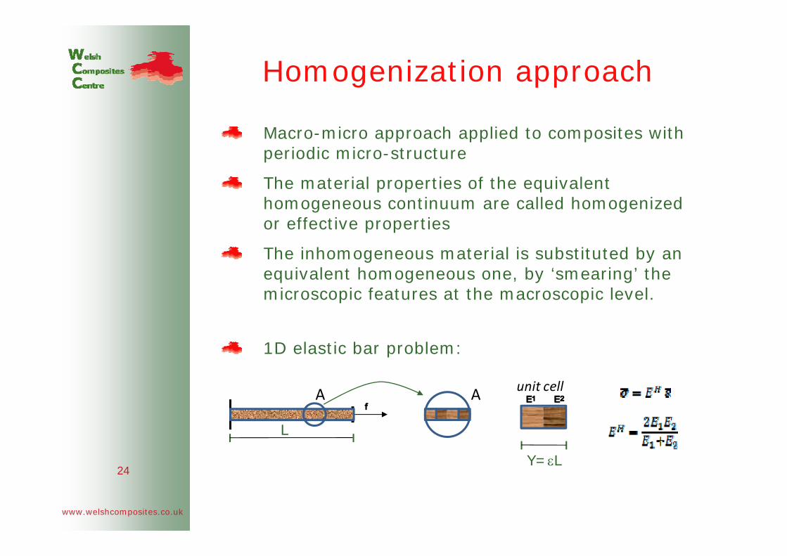
Homogenization approach
Macro-micro approach applied to composites with periodic micro-structure
The material properties of the equivalent homogeneous continuum are called homogenized or effective properties
The inhomogeneous material is substituted by an equivalent homogeneous one, by ‘smearing’ the microscopic features at the macroscopic level.
1D elastic bar problem:
24
L
A A
Y=εL
unit cell

www.welshcomposites.co.uk
OUTLINE
25
The topics that are covered include:
Case studiesStringer design, rib design and some crush analysis
Steps in the numerical analysis of composite structures
Composite laminates definition and design
Stress strain relations for composite materials from macroscopic and microscopic approaches
Effective properties for isotropic, orthotropic and anisotropic materials and overview of mixture and homogenization approaches
Laminates damage, failure criteria and buckling
Numerical simulation of a composite stiffened panel using the FE software HYPERWORKS
Preparation of input file and analysis of results

Laminates damage
• Laminate composite structure develop
Matrix cracks Fibre-matrix debondingFibre fractureDelamination
loss of stiffness andloss of stiffness andof strength of the material!of strength of the material!
Once the mechanical properties of the layers are known, the initial failure of a layer within a laminate or structure can be
predicted by applying an appropriate failure criterion.Failure criterion is used only to check whether allowables are
exceeded
26

Composite (anisotropic) failure criterion
• Layer failure index (F>1)
Maximum stress criterion
Maximum strain criterion
Tsai-Hill anisotropic criterion:
• Bonding failure index
• Global final failure index for composite elementMaximum of all computed layer and bonding failure indices
27

Sudden large out-of-plane displacements when the critical value of the load is reached.
Compressed bar Compressed isotropic plate
Linear Buckling Analysis
Search for the smallest λ (denoted by λcr ) with U ≠ 0 such that
(K-λKG)U = 0
K: material stiffness matrix, KG: geometric stiffness matrix Pcr=λcr Pref Critical or buckling load Critical or buckling load
Buckling
28
b σc=KE(h/b)2

Delamination buckling
• local delamination can be seen as a crack in the bond
• low velocity impacts and defects in manufacturing can lead to local delamination
29
Delamination buckling can be analysed as a classical linear problem of buckling of a strip with fixed ends

www.welshcomposites.co.uk
OUTLINE
30
The topics that are covered include:
Case studiesStringer design, rib design and some crush analysis
Steps in the numerical analysis of composite structures
Composite laminates definition and design
Stress strain relations for composite materials from macroscopic and microscopic approaches
Effective properties for isotropic, orthotropic and anisotropic materials and overview of mixture and homogenization approaches
Laminates damage, failure criteria and buckling
Numerical simulation of a composite stiffened panel using the FE software HYPERWORKS
Preparation of input file and analysis of results
www.welshcomposites.co.uk
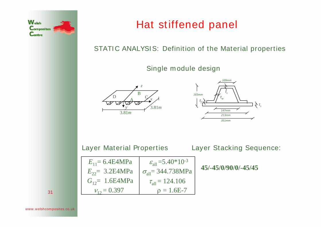
Hat stiffened panel
STATIC ANALYSIS: Definition of the Material properties
Single module design
Layer Material Properties Layer Stacking Sequence:
45/-45/0/90/0/-45/45
31
351mm
109mm
tctw
tstf
147mm
213mm
165mm
z
y
x
3.81m3.81m
AB
CD
E11= 6.4E4MPa E22= 3.2E4MPaG12= 1.6E4MPa
ν12 = 0.397
εall =5.40*10-3
σall= 344.738MPaτall = 124.106
ρ = 1.6E-7

Hat stiffened plate
32
Nx
q
Finite element mesh ⇒

www.welshcomposites.co.uk
Thank you for your attention!