compression behavior of stack bonded clc masonry
TRANSCRIPT
1
EXPERIMENTAL STUDY ON COMPRESSION BEHAVIOR OF 1
FIBER REINFORCED CELLULAR CONCRETE 2
STACK BONDED MASONRY PRISMS 3
4
Abdur Rasheed. M, Dr. Suriya Prakash. S 5
6
Biography: Abdur Rasheed M is a Ph.D. candidate at Indian Institute of Technology 7
Hyderabad. His research area includes sustainable construction and development of resilient 8
fiber reinforced foam concrete. He completed his graduate degree in structural engineering 9
from IIT Hyderabad and bachelor degree in civil engineering from National Institute of 10
Technology Calicut. He also worked shortly as a structural design engineer in Zedcon 11
Consultants Pvt. Ltd. India. 12
Dr. S. Suriya Prakash is currently working as an associate professor at IIT Hyderabad. Before 13
joining IIT-H, he worked with Structural Inc. USA, a design firm in strengthening of concrete 14
structures. He has completed his PhD from Missouri University of Science and Technology, 15
USA. He has authored more than thirty-five peer reviewed journal papers on the behavior of 16
reinforced concrete columns under combined loading and strengthening of structural elements 17
with FRP composites. He is a member of ACI and ASCE, USA. 18
ABSTRACT 19
This paper presents the stress-strain behavior of structural synthetic fiber reinforced Cellular 20
Lightweight Concrete (CLC) stack bonded prisms under axial compression. Masonry 21
compressive strength is typically obtained by testing stack bonded prisms under compression 22
normal to its bed joint. CLC prisms of cross sectional dimensions of 200 mm x 150 mm (7.87 23
in. x 5.90 in.) with an overall height of 470 mm (1.54 ft) were cast with and without different 24

2
dosages of synthetic fiber reinforcement. Polyolefin was used as a structural fiber 1
reinforcement at different volume fractions (V.F) of 0.22%, 0.33%, 0.44% and 0.55% with and 2
without micro fiber dosage of 0.02%. Experimental results indicate that the presence of fibers 3
helps in the improvement of strength, stiffness and ductility of CLC stack bonded prisms under 4
compression. Test results also signifies that the hybrid fiber reinforcement provides better crack 5
bridging mechanism both at micro and macro levels when compared to only macro fibers. 6
Simple analytical models were developed for stress-strain behavior of CLC blocks and stack 7
bonded CLC prisms based on the experimental results with and without fibers under 8
compression. 9
10
Keywords: Analytical models; CLC Prisms; Compression; Macro/Micro Fibers; Stress-Strain 11
Curves; 12
INTRODUCTION 13
Usage of lightweight concrete blocks has seen a rapid growth in the recent years and is slowly 14
replacing the conventional clay bricks in masonry construction. The usage of Cellular 15
Lightweight Concrete (CLC) blocks gives a sustainable construction solution. The production 16
process of CLC has low carbon blueprint and uses fly ash as a major ingredient1. Production 17
of clay bricks involves use of agriculturally suitable soil as a raw material. Manufacture of a 18
hundred thousand bricks requires approximately fifty tons of firewood. Therefore, CLC can 19
provide a potential alternative to the replacement of conventional red clay burnt bricks. 20
Additional benefits of using CLC include high strength/weight ratio, improved thermal 21
insulation1 and better acoustic absorption2 compared to normal concrete. CLC blocks require 22
less number of mortar layers due to reduction in the number of joints. Therefore, CLC walls 23

3
can be assembled on construction sites at a faster rate compared to the traditional clay brick 1
walls. However, the problem due to its brittle mode of failure under shear, tension and 2
compression needs to be addressed. Studies on cohesive clay and soil cement samples have 3
shown that the addition of synthetic polypropylene fibers increases the tensile and unconfined 4
compressive strength upto ten millimeter length of fiber3. It was further stated that beyond this 5
length, the strength is still increasing but at a slower rate. Addition of fibers can improve the 6
ductile behavior of CLC under shear, tensile and compression loadings making it suitable for 7
seismic applications. This improvement can be attributed to arresting of micro cracks in 8
FRCLC whereas the unreinforced specimen is observed to have crack localization in the major 9
crack plane. Micro cracks are referred to very small cracks that form in concrete but are not 10
visible to the naked eye. Major cracks have significant crack opening with width greater than 11
0.2mm. It is worth mentioning that CLC is relatively a softer material with no coarse 12
aggregates. Its compressive modulus of elasticity is typically about one tenth of the normal 13
weight concrete. Therefore, the failure mechanism of CLC will be very different when 14
compared to the conventional concrete specimens. 15
Non-engineered unreinforced masonry (URM) buildings constitute a significant proportion 16
of the buildings around the world1,4,5. Performance evaluation and structural stability analysis 17
of URM buildings in the past revealed that URM are highly vulnerable to failure particularly 18
during seismic loading (Fig. 1). URM buildings exhibit failure mode of brittle nature when 19
subjected to lateral loads during seismic events and usually undergo complete collapse4 (Fig. 20
15). Load bearing constructions are made using clay brick masonry. Infill walls made of brick 21
masonry are also commonly used as partitions in reinforced concrete and steel framed 22
structures. Both the masonry load bearing walls and infill walls were heavily damaged during 23
the past earthquakes6. Several studies in the past have focused on the behavior of URM 24

4
assemblies under compression7–9. Previous experimental investigations on URM assemblies10–1
13 has shown that the brick strength of about 5 MPa (0.73 ksi) is typically used in the developing 2
countries10. Moreover, softness of these bricks cause a different state of stresses to develop 3
unlike in the case of masonry made with stiffer and stronger bricks. 4
5
The strength and the seismic performance of CLC structures can be improved by engineering 6
fiber reinforcement into CLC masonry system. Addition of fibers in CLC masonry can increase 7
the structural integrity by reducing permeability and leading to better durability and increased 8
life. Researchers14 in the past have reported a ductile elasto-plastic load-deflection behavior of 9
fiber reinforced cellular concrete subjected to different modes of loading. Chopped 10
polypropylene in CLC as fiber reinforcement has shown improvement in shear behavior of 11
small structural elements15. Use of micro fibers (Fibrillated) enhance the pre-cracking behavior 12
of masonry prisms by arresting cracks at the micro scale, while macro (Structural) fibers induce 13
ductile behavior in the post-peak region by arresting the structural cracks. Post-peak residual 14
strength and ductile behavior of CLC masonry can be attained by the addition of fibers. 15
However, a thorough knowledge about the behavior and the failure modes of engineered fiber 16
reinforced CLC masonry is necessary to formulate the design guidelines. The objective of this 17
study is outlined as follows. (i) To understand the stress-strain behavior of stack bonded 18
masonry prisms made of sustainable, affordable and cost effective synthetic fiber reinforced 19
CLC blocks under compression. (ii) To prove that the developed fiber reinforced CLC has 20
better performance compared to that of conventional clay brick masonry and autoclaved 21
aerated concrete (AAC) block masonry in particular under the post-peak region with a higher 22
ductility. (iii) To propose a simple design equation for CLC prisms reinforced with hybrid fiber 23
reinforcements under axial compression. 24

5
RESEARCH SIGNIFICANCE 1
The results presented in this paper are only a part of the study focusing on the subject of 2
compression behavior of stack bonded CLC masonry prisms. Flexural and tensile behavior of 3
CLC blocks was studied and reported in a companion paper by the authors11,16. CLC is 4
relatively a softer material (low stiffness) compared to the normal concrete. Therefore, macro 5
fibers are expected to significantly influence the stress-strain behavior under compression due 6
to their contribution in resisting lateral tensile stresses arising from Poisson’s effect and 7
dilatancy. It is worth mentioning that no previous investigation in the past has focused on the 8
influence of synthetic structural fiber reinforcement on strength, stiffness and failure modes of 9
CLC stack bonded prisms. 10
EXPERIMENTAL INVESTIGATION 11
The scope of the experimental investigation includes the following: (i) To characterize the 12
mechanical properties including stress-strain curves for CLC blocks, mortar and CLC prisms 13
under compression. (ii) To study the effectiveness of synthetic fiber reinforcement on energy 14
dissipation capacity (toughness index) and failure modes on the stress-strain behavior of fiber 15
reinforced CLC prisms under compression. CLC blocks with varying fiber dosages were cast 16
and tested to get stress-strain curves under compression. Mortar cylinders with cement and 17
sand (1:6 by weight) were cast and tested under compression to obtain the bed joint stress- 18
strain curve characteristics. Thereafter, CLC stack bonded prisms with fiber reinforced CLC 19
blocks and normal cement mortar, were cast and the influence of varying fiber reinforcement 20
on the composite action of masonry CLC prisms under axial compression behavior is studied. 21
Fibers are added in the CLC masonry to provide necessary tensile and shear resistance under 22
the action of lateral loads. The developed CLC masonry can be used as a load bearing masonry 23

6
construction, which would be largely subjected to compressive stresses. The objective of 1
adding synthetic fibers was not to increase the compressive strength but more importantly to 2
improve the post-peak behavior under tension, flexure, compression and their combinations. 3
Materials 4
Four basic materials were used for control CLC mixture viz., 53 grade OPC (Ordinary Portland 5
Cement), siliceous type class F fly ash from National Thermal Power Corporation (NTPC), 6
potable water and sunlite foam. Lime content in class F flyash is typically less than 10%. The 7
mix had fly ash 833kg/m3 (1404.1 lb/yd3), cement 277 kg/m3 (466.9 lb/yd3), water 277 kg/m3 8
(466.9 lb/yd3) and foam 1.4 kg/m3 (2.4 lb/yd3) for a cubic meter of CLC. It is typical to use 9
water cement ratio in the range of 0.4 to 1.25, with materials of lowest densities requiring the 10
highest ratios17. Water cement ratio of 1.0 is used in this investigation. However, fly ash is 11
expected to act as a binder as soon as the cement paste undergoes hydration process. The 12
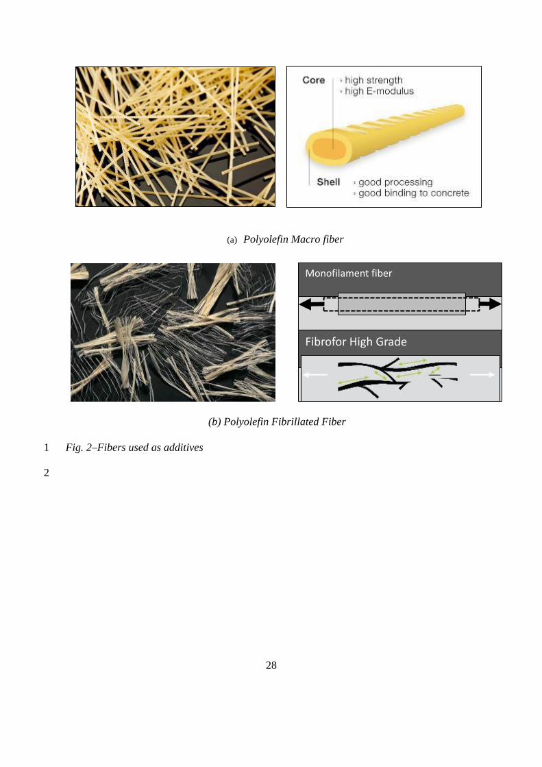
additives are bi-component macro fiber and micro fiber (fibrillated)18 as shown in Fig. 2a and 13
Fig. 2b, respectively . The mechanical properties of fibers are mentioned in Table 1. 14
15
Details of Specimens 16
Experimental program includes testing of CLC blocks with and without fiber reinforcement, 17
mortar cylinders and CLC stack bonded prisms constructed with CLC blocks and mortar. Stack 18
bonded CLC prism with cement mortar as joints and CLC blocks with and without fiber 19
reinforcement is shown schematically in Fig. 3. Details of the specimen and fiber dosage are 20
shown in Table 2. 21
22
23
7
Mixing, Placing and Curing 1
The dry raw materials such as cement and fly ash were introduced into the meta-stabilizing 2
mixer first and mixed thorough enough to ensure even distribution of the contents. Potable -3
water was then added to the mixer until all the dry raw materials are converted to wet mix. The 4
preformed foam19 was introduced at a rate of 35 gm/ sec for 40 seconds to the meta-stabilizing 5
mixer. Additional three minutes of mixing was done along with the fibers to get uniform 6
consistency and to form slurry of CLC. Thereafter, this slurry was poured into cuboidal moulds 7
of 200 mm x 150 mm (7.87 in. x 5.90 in.) cross section and 600mm (1.97 ft) length. Specimens 8
were demolded after 24 hours and curing was done as per IS-456 2000 (Plain and Reinforced 9
Concrete - Code of Practice [CED 2: Cement and Concrete]). At present, there are no standards 10
available for mix design of CLC using large amounts of fly ash. In this study, a large number 11
of trials were carried out to achieve a target density of 900 ± 50 kg/m3. The quantities of various 12
materials were arrived based on trial mixes. Target density of CLC was kept as 900±50 kg/m3 13
(1517±84 lb/yd3). Density of CLC was not much affected by the addition of fibers since the 14
specific gravity of CLC mix was in the same range as that of fibers (910 kg/m3 (1533.8 lb/yd3)). 15
It is worth mentioning that CLC used in this study, does not have coarse and fine aggregates 16
as typical in other lightweight concretes. CLC consist of only cement, flyash and foaming 17
agent. Studies in the past has revealed that optimum air content at which maximum strength to 18
weight ratio for foam concrete is around 40%20. At this air content, the density of foam concrete 19
tends to be close to 750 kg/m3 (1264.2 lb/yd3). However, for this study a total void ratio of 20
about 0.35 is used in order to achieve 900±50 kg/m3 (1517±84 lb/yd3) density. Water 21
absorption tests were carried out on CLC blocks. The water absorption was found to be 15 to 22
20%, which is comparable to that of existing clay brick masonry. Stack bonded prisms were 23

8
cast using blocks of 200 x 150 x 110 mm (7.87 in. x 5.90 in. x 4.33 in.). Four CLC blocks were 1
used for constructing each prism. A cement mortar with cement: sand weight ratio of 1:6 and 2
10 mm thickness was used for joints. Dimensions of the cast prism are shown in Fig. 3. After 3
curing for 28 days, compression test on CLC were carried out in displacement control mode. 4
5
Test Method 6
The quality of masonry is usually defined by its compressive strength. The American Society 7
for Testing and Materials (ASTM) provides standardized test methods for compression testing 8
of these specimen types. In terms of saving time and money during the design and construction, 9
it is desirable to ensure that the specified properties of masonry assemblages are satisfied using 10
simple and economical tests21. Testing of masonry prisms is economical and practical than 11
full-scale testing of masonry assemblages. The compressive strength of masonry is represented 12
as ƒ'm, which is specified by an engineer and used throughout masonry design procedures. This 13
strength has upper and lower bounds governed by the specific building code adopted for 14
construction. 15
The loading surfaces of the prisms were scraped and leveled to ensure a smooth contact area 16
prior to testing. The prisms were tested using the servo controlled compression testing machine 17
(Fig. 4). Soft capping using fiberboard was carried out to provide a flat bearing surface in order 18
to distribute the load uniformly to the specimen. Testing was stopped when the load dropped 19
by more than 30% of its maximum value. The load - displacement data were recorded through 20
a Data Acquisition (DAQ) System. Though, there exist no standards for testing fiber reinforced 21
CLC stack bonded prisms under compression, ASTM C1314 – 16 (Standard test method for 22
compressive strength of masonry prisms, 2012), IS 1905-1987 (Structural use of unreinforced 23

9
masonry), and IS 3495-1992 (Parts 1-4 : Methods of tests of burnt clay building brick) 1
provisions were used as a guideline to establish stress-strain curves of CLC prisms under 2
compression. Testing of prism specimen in compression was done in a servo controlled 3
compression testing machine by applying load at a rate of 0.1 kN/sec (0.022 kips/sec) upto70% 4
of the peak load. Thereafter, the loading was applied in displacement control mode at a rate of 5
0.001mm/sec (3.94x10⁻⁵in./sec). The applied load was measured through load cell and 6
displacements were measured in the direction of loading using Linear Variable Displacement 7
Transducers (LVDTs) of 20 mm (0.78 in) stroke and 160 mm (6.3 in.) gauge length mounted 8
on the prisms as shown in Fig. 4. 9
EXPERIMENTAL RESULTS AND DISCUSSION 10
Behavior under Compression 11
CLC Blocks with Varying Fiber Dosages 12
Development of fiber reinforced CLC blocks and their behavior under flexure and compression 13
is reported in the companion paper by the authors11. The compression behavior of CLC blocks 14
is briefly explained here for comparison with the prism behavior. Strength of fiber reinforced 15
CLC blocks were obtained by testing of cylinders under compression. The peak compressive 16
strength of CLC was found to be varying with a coefficient of variation of 10 to 15% with 17
respect to fiber dosage. Only average stress-strain response is presented here for comparisons. 18
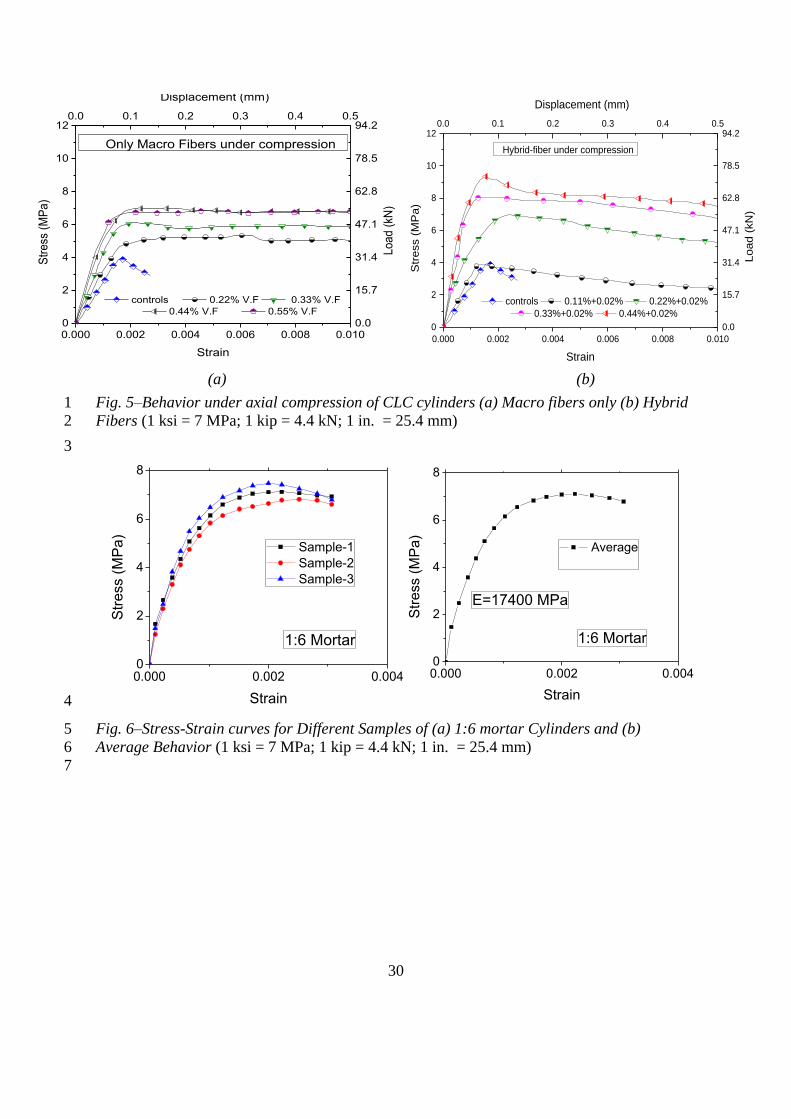
Unreinforced CLC cylinders subjected to compression showed a linear stress-strain behavior 19
(Fig. 5a) upto 30% of the peak stress. Subsequently, it became nonlinear and continued up to 20
the peak stress due to adjustment of air-voids at higher loads. Less resistance to the applied 21
strain was observed after attaining the peak load, resulting in quite a sudden collapse of the 22
prism. 23

10
The pre-cracking behavior of CLC cylinders with and without macro and hybrid fibers were 1
similar. However, there was a marginal increase in the elastic stiffness (Fig. 5a, 5b). The peak 2
strength increased with the increase in fiber dosage in both the cylinders with macro and hybrid 3
fibers. As the displacement entered the post-peak region, load drop was not observed rather the 4
post-peak load followed almost a constant value close to peak load indicating relatively less 5
degradation in post-peak stiffness. Hybrid fiber reinforcement resulted in better performance 6
compared to that of CLC cylinders with macro fibers (Fig. 5b). Hybrid-fiber reinforcement 7
showed an appreciable increase in elastic stiffness upto the peak load. However, the load 8
carrying capacity reduced in the post-peak region without undergoing much reduction in 9
stiffness (Fig. 5b). The peak load in hybrid specimens increased upto about 30% with respect 10
to that of cylinders with only macro fibers. Compressive strength of CLC cylinders were found 11
to be in the range of 4 to 8 MPa (0.58 to 1.16 ksi). 12
13
Compression Behavior of Mortar 14
Ordinary Portland cement (OPC), conforming to IS 8112 1989 (Specification for 43 grade 15
ordinary Portland cement) and river sand confirming to IS: 2116-1980 (specification for sand 16
for masonry mortars) were used for the preparation of mortar cylinders. A high water-cement 17
ratio of 0.75 was used in the casting of mortar cylinders to ensure workability. Cylinders of 18
dimensions 200 mm (7.87 in.) length and 100 mm (3.93 in.) diameter were cast and tested 19
under axial compression after 28 days of curing. Compressive stress-strain curves of mortar 20
cylinders and its average behavior is shown in Fig. 6. The average behavior is arrived using a 21
parabolic curve fit on the data scatter with and R2 value of 0.92. 22
The deformation of specimens was measured over a gauge length of 40 mm (1.58 in.) with 23
the help of 20mm (0.79 in.) LVDTs mounted on the specimen. Testing was carried under 24

11
displacement control mode at a rate of 0.01 mm/sec (3.94x10⁻⁴in./sec) using servo controlled 1
compression testing machine. Test results and behavior of 1:6 mortar mix is shown in the Fig. 2
6. It is worth mentioning that the average elastic stiffness of mortar was about 17400 MPa 3
(2523.66 ksi) and is much higher than the stiffness of CLC blocks (about 3000 to 3500 MPa 4
(435.11 to 507.63 ksi)). Therefore, the behavior of CLC masonry will be similar to that of low 5
stiff brick and high stiff mortar combinations in URM structures as reported by the previous 6
researchers (Prakash22; Sarangapani et al.23; Kaushik et al.24). 7
8
Behavior of CLC Prisms with and without Fiber Reinforcement 9
A total of thirty CLC prisms was cast with different fiber dosages and tested in three series. 10
Series I was the control one with no fiber reinforcement. Series II had only macro reinforcement 11
in the blocks whereas, the series III included various dosages of macro fibers in combination 12
of 0.02% fixed micro fiber dosage. A minimum of three specimens was tested for each series 13
to ensure the consistency of results. Test results of CLC stack bonded prisms in compression 14
for all the three series of specimens are presented in Table 3. Coefficient of variation of prism 15
strength was less than 15% and the average results are reported for comparison of the behavior 16
of CLC prisms between hybrid fibers and macro fibers. 17
Control CLC Prisms with No Fibers 18
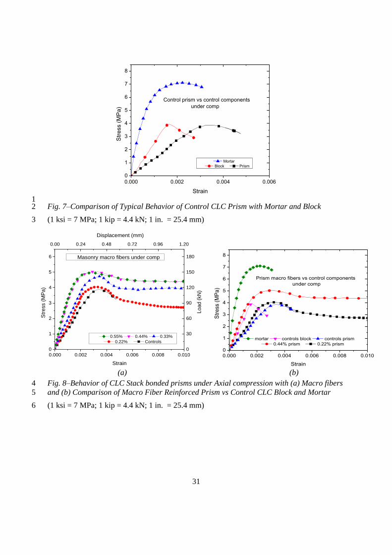
Stress-strain curve for the control CLC prism under axial compression exhibited a linear 19
behavior up to 33% of the peak load (Fig. 7). Soon after the peak load was attained, the failure 20
was quite sudden as the specimen collapsed showing almost negligible resistance to the applied 21
strain loading. Fig. 7 shows that the strength of the unreinforced prism (3.9 MPa (0.57 ksi)) 22
was closer to that of block strength. The elastic modulus of the mortar (17400 MPa) was up to 23
six times that of block (3000 MPa (435.11 ksi)). However, the elastic modulus of the prism 24

12
assembly is lesser than that of both mortar and block. The elastic modulus of the prism was 1
1400 MPa (203.05 ksi) which is less than 50% of the modulus of CLC block (3000 MPa 2
(435.11 ksi)). This is similar to combination of soft brick and high stiff mortar brick masonry 3
prisms previously studied (Prakash et al.22, Kaushik et al.24). This combination results in tri-4
axial compression in blocks and bi-axial tension and uniaxial compression in mortar. The 5
failure was initiated by tension cracking in the mortar followed by its propagation as splitting 6
cracks in the CLC blocks leading to the overall failure of the prism. 7
CLC Prisms with Macro Fibers 8
The behavior of macro fiber reinforced prism was similar to that of unreinforced prisms until 9
the peak load with slight increase in the initial modulus of elasticity (Fig. 8a). The enhancement 10
in modulus of elasticity can be attributed to the higher stiffness contribution and much higher 11
modulus of elasticity of fibers (around 10,000 MPa (1450.38 ksi)) compared to that of the 12
parent CLC matrix material (around 3000 MPa (435.11 ksi)). This increase in elastic modulus 13
is marginal due to the low volume fraction of fibers considered in the study. Fig. 8a shows the 14
improvement in the stiffness and strength of fiber reinforced prisms compared to that of 15
unreinforced prisms. The peak strength of fiber reinforced prisms lies between that of mortar 16
and block. The stiffness of unreinforced prism was lesser than that of unreinforced block. With 17
the addition of fiber reinforcement, the elastic modulus of the prism was improved and 18
remained between the mortar and block modulus. As the CLC block material forms the major 19
volume fraction of the prisms, the stress-strain behavior is closer to that of CLC blocks than 20
mortar. The peak strength increased with the increase in fiber dosage. The post-peak region of 21
the fiber reinforced specimen showed lesser strength degradation and higher displacement at 22
failure. The area under the stress-strain curve (strain energy absorption) increased with increase 23
in the fiber dosage. 24

13
The behavior of macro fiber reinforced prisms (0.22% and 0.44%) is compared with the 1
behavior of block and mortar in Fig. 8b. It was observed that the addition of high fiber dosage 2
resulted in improvement of elastic modulus of prism which is higher on comparison with the 3
control block. This can be attributed to the higher stiffness contribution and much higher 4
modulus of elasticity of fibers (around 10,000 MPa (1450.38 ksi)) compared to that of the 5
parent CLC matrix material (around 3000 MPa (435.11 ksi)). However, even after the addition 6
of high fiber dosage, modulus of prisms (3200 MPa (464.12 ksi)) could not reach the elastic 7
modulus of mortar (17400 MPa (2523.66 ksi)). The failure of the macro fiber reinforced prisms 8
was due to initiation of tension cracks in mortar and subsequent propagation to blocks leading 9
to splitting failure. The fibers in CLC blocks helped in resisting the cracking and contributed 10
to the post-peak load resistance. This helped to increase the displacement at failure. 11
CLC Prisms with Hybrid Fibers 12
Hybrid-fiber reinforced CLC prisms showed a significant increase in the elastic modulus. 13
While the softening behavior was more pronounced in the post-peak region in comparison to 14
macro fiber reinforced specimen, degradation in stiffness was lesser (Fig. 9a). Fig. 9b shows 15
the improvement in the stiffness and strength of hybrid fiber reinforced prisms compared to 16
that of macro fiber and unreinforced prisms. The peak strength of hybrid fiber reinforced prisms 17
was higher than the blocks and its elastic modulus was lying between the blocks and mortar. 18
The stress-strain curves for prisms reinforced with only macro fibers and hybrid fibers are 19
compared in Fig. 9b. The peak compressive load in hybrid fiber reinforced prisms increased 20
when compared with CLC blocks and CLC prisms with only macro fiber reinforcement. This 21
can be explained by the better arresting of cracks at both the micro and macro scales which led 22
to the increase in peak compressive strength and better post-peak behavior. Post-peak behavior 23
is improved in terms of residual load carrying capacity and compressive toughness index. Peak 24
14
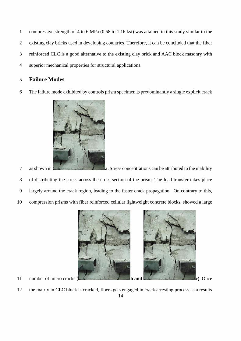
compressive strength of 4 to 6 MPa (0.58 to 1.16 ksi) was attained in this study similar to the 1
existing clay bricks used in developing countries. Therefore, it can be concluded that the fiber 2
reinforced CLC is a good alternative to the existing clay brick and AAC block masonry with 3
superior mechanical properties for structural applications. 4
Failure Modes 5
The failure mode exhibited by controls prism specimen is predominantly a single explicit crack 6
as shown in a. Stress concentrations can be attributed to the inability 7
of distributing the stress across the cross-section of the prism. The load transfer takes place 8
largely around the crack region, leading to the faster crack propagation. On contrary to this, 9
compression prisms with fiber reinforced cellular lightweight concrete blocks, showed a large 10
number of micro cracks ( b and c). Once 11
the matrix in CLC block is cracked, fibers gets engaged in crack arresting process as a results 12

15
more number of micro cracks emerges in the material as shown in Fig. 10d. The fibers in the 1
CLC blocks formed a closed network and resisted the formation of major cracks. Elastic 2
modulus of fiber reinforced blocks was lesser than that of the mortar. This resulted in tri-axial 3
compression in CLC blocks and uniaxial compression and bi-axial tension in the mortar joint 4
which is schematically presented in Fig. 10e. Failure progression of CLC prisms was due to 5
crack initiation in mortar leading to further propagation in CLC blocks leading to overall 6
failure. Presence of fibers in the CLC blocks led to better crack resistance leading to improved 7
post-peak behavior. With the increase in load, more number of micro cracks developed along 8
the direction of loading. This indicates the possibility of stress concentration in the crack 9
region, which led to faster crack propagation. Fibers in the blocks bridged the cracks and 10
prevented its further propagation leading to lesser strength degradation with higher strains at 11
failure. 12
ANALYTICAL INVESTIGATION 13
MODELS FOR FIBER REINFORCED CLC BLOCK AND STACK BONDED PRISMS 14
Fiber Reinforced CLC Block 15
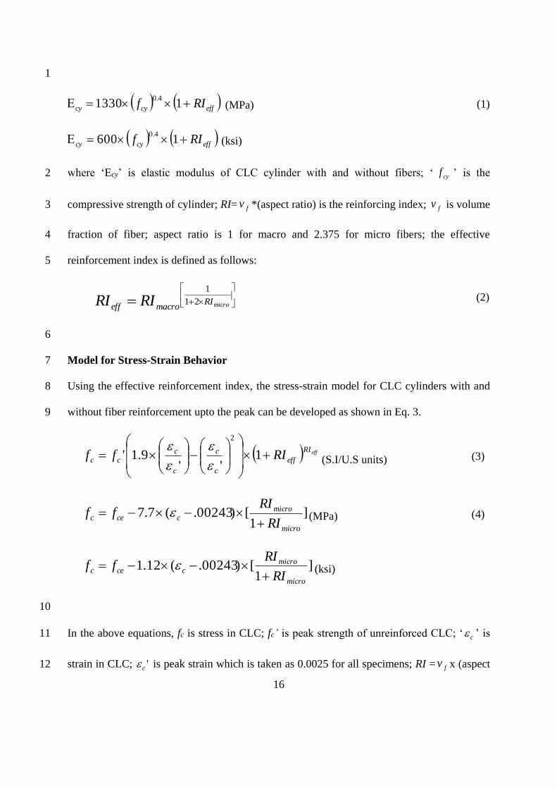
Equation for Elastic Modulus 16
The elastic modulus of the CLC (Ecy) is found to be varying with the compressive strength (fcy) 17
as shown in Eq. 1. Equations were developed based on regression analysis based on the limited 18
test data. The goodness of fit values for all the equations lie in a range of 0.9-0.98. Microsoft 19
Excel was used for developing the equations. In order to find the variation of elastic modulus 20
with the percentage of fiber, a term called effective reinforcement index (RIeff) is introduced 21
(Eq. 2). Relation between ‘Ecy’ and compressive strength (fcy) in terms of RIeff can be expressed 22
as follows: 23
16
1
effcycy RIf 113304.0
(MPa) (1)
effcycy RIf 16004.0
(ksi)
where ‘Ecy’ is elastic modulus of CLC cylinder with and without fibers; ‘ cyf ’ is the 2
compressive strength of cylinder; RI= fv *(aspect ratio) is the reinforcing index; fv is volume 3
fraction of fiber; aspect ratio is 1 for macro and 2.375 for micro fibers; the effective 4
reinforcement index is defined as follows: 5
microRImacroeff RIRI 21
1
(2)
6
Model for Stress-Strain Behavior 7
Using the effective reinforcement index, the stress-strain model for CLC cylinders with and 8
without fiber reinforcement upto the peak can be developed as shown in Eq. 3. 9
effRI
eff
c
c
c
ccc RIff
1
''9.1'
2
(S.I/U.S units) (3)
]1
[)00243.(7.7micro
microccec
RI
RIff
(MPa) (4)
]1
[)00243.(12.1micro
microccec
RI
RIff
(ksi)
10
In the above equations, fc is stress in CLC; fc’ is peak strength of unreinforced CLC; ‘ c ’ is 11
strain in CLC; 'c is peak strain which is taken as 0.0025 for all specimens; RI = fv x (aspect 12

17
ratio); fv is volume fraction of fibers; ‘ cef ’ is the compressive strength of cylinder at peak 1
strain 'c . The effective reinforcement index of the hybrid fiber combination is defined as per 2
Eq. 2. A straight line defined by Eq. 4 gives the post-peak behavior of the curves. Comparison 3
of predicted stress-strain behavior and experimental data for different fiber reinforcement is 4
shown in Fig. 11. Analytical Investigations using simple models have shown that the goodness 5
of fit values for all the equations lie in a range of 0.9-0.98. Therefore, the term close prediction 6
is used to describe the goodness of fit. A close prediction indicates that simple equations 7
proposed for elastic modulus and stress-strain behavior of CLC blocks with and without fiber 8
reinforcement are working well. 9
10
Fiber Reinforced CLC Prisms 11
Compressive Strength of Fiber Reinforced CLC Prisms 12
Compressive strength of fiber reinforced CLC prism can be estimated from the mortar and 13
CLC block strength as follows: 14
15
effRI
eff
m
cy
p RIf
ff
11.0
1.1
(MPa) ( 5)
effRI
eff
m
cy
p RIf
ff
1145.01.0
1.1
(ksi)
16
where fp is compressive strength of prism; fm is compressive strength of mortar for 1:6 grade 17
it is 6.9MPa (1.01 ksi); fcy is compressive strength of CLC block; RI = fv * aspect ratio; fv is 18

18
volume fraction of fibers; aspect ratio is 1 for macro and 2.375 for micro; Effective fiber 1
reinforcement index (RIeff ) for hybrid specimens is defined as per Eq. 2. 2
3
Elastic Modulus of Fiber Reinforced CLC Prisms 4
The elastic modulus of the CLC prism with and without fibers was found to be varying with 5
the compressive strength of the prism as shown in Eq. 6. A parameter called reinforcement 6
index (RI) is defined to find the variation of elastic modulus with respect to the percentage of 7
fibers. An effective reinforcement index was defined as per Eq. 2 to include the hybrid fiber 8
reinforcement combination. A relationship between modulus of elasticity (Ep) and compressive 9
strength (fp’) expressed as follows: 10
5.2
40
pp f (MPa) (6) 11
5.2
32.0
pp f (ksi) 12
where ‘Ep’ is the elastic modulus of prism with and without fibers; fp’ is the compressive 13
strength of the prism; 14
Model for Stress-Strain Behavior of Fiber Reinforced CLC Prisms 15
The stress-strain model for prisms with and without fiber reinforcement for the pre-peak 16
behavior is defined as follows: 17
18
(in S.I /U.S units)
(7)
19
The post-peak behavior can be defined using the Eq. 8 as follows. 20
2
''43.1'
pp ff

19
(in S.I/U.S units)
(8)
1
where fp is stress in the prism with and without fibers; fp’ is peak strength of prism as defined 2
in Eq. 5; ‘ϵ’ is strain in the prism; ϵ’ is peak strain of prisms which is taken as 0.003. 3
Comparison of predicted stress-strain behavior of prisms with and without fibers and 4
experimental data for different fiber reinforcement is shown in Fig. 12. A close prediction 5
indicates that the simple equations proposed for elastic modulus and stress-strain behavior of 6
CLC blocks and prisms with and without fiber reinforcement are giving very close predictions 7
and hence can be used for design purposes. 8
FURTHER RESEARCH 9
Cost analysis indicates that the cost of fiber reinforced CLC is only 20% higher than the normal 10
CLC. Overall life-cycle analysis indicates the beneficial effects of adding fibers overweigh the 11
additional cost incurred due to fiber addition. Moreover, cheaper and cost effective fibers are 12
increasingly available in the market. Compression tests on CLC prisms constructed with mortar 13
of low strength and modulus than CLC blocks would be interesting. This combination would 14
induce tri-axial compression in mortar and bi-axial tension and uniaxial compression on the 15
CLC blocks and therefore the failure modes would be very different to what is reported in this 16
study. A study on the effect of addition of fibrillated fibers on mortar and its influence on 17
compression behavior of CLC prisms would also be interesting and is scope for further work. 18
CONCLUSIONS 19
2
'
'09.01
'76.0
'
pp ff

20
CLC is sustainable, light in weight and the performance of CLC can be enhanced through 1
addition of fibers for improvement in post-peak strength degradation and higher strains at 2
failure. The effect of adding synthetic fibers to CLC was studied by testing CLC stack bonded 3
prisms with various fiber dosages under compression. Based on the results present in this study, 4
the following conclusions can be drawn: 5
1. The compression behavior of composite CLC prisms was similar to that of individual 6
CLC cylinders under compression. Compressive strength of prisms increased 7
progressively with the increase in fiber dosage. Compressive strength increased up to 8
28.3% for 0.55% volume fraction of macro fiber when compared to that of control 9
prisms. Rate of increase in strength decreased with increase in fiber dosage. 10
2. Elastic modulus of fiber reinforced CLC blocks was lesser than that of the mortar. This 11
resulted in tri-axial compression in CLC blocks and uniaxial compression and bi-axial 12
tension in the mortar joint. Failure progression of CLC prisms was due to crack 13
initiation in mortar leading to further propagation in CLC blocks leading to overall 14
failure. Presence of fibers in the blocks led to better crack resistance and led to lesser 15
strength and stiffness degradation when compared to control prisms. 16
3. Minimal change was observed in compressive strength and toughness index, when the 17
performance of 0.44% and 0.55% volume fraction of macro fibers were compared. 18
Hybrid fiber addition increased the compressive strength up to 45.2% for 0.44% volume 19
fraction of macro fibers with micro fibers of 0.02% when compared to control CLC 20
prisms. 21
4. Fiber reinforced CLC stack bonded prisms showed a good composite behavior under 22
compression. This is due to the fact that the difference in strength as well as stiffness 23
between mortar and fiber reinforced blocks reduced with increase in fiber dosage. 24

21
However, peak compressive strength of the composite stack bonded prisms was closer 1
to the low strength block due its higher volume fraction in the prism. 2
5. Simple equations were proposed for elastic modulus and stress-strain behavior of CLC 3
blocks and prisms with and without fiber reinforcement. A good match was observed 4
between the predictions and test results. 5
6
7
NOTATION: 8
Ecy = elastic modulus of the CLC 9
effRI = Effective fiber reinforcement index 10
fcy = compressive strength of cylinder 11
fv = volume fraction of fiber 12
c = strain in the cylinder 13
'c = peak strain of cylinder 14
fce = compressive strength of cylinder at peak strain 'c 15
fm = compressive strength of mortar 16
pf = stress in the prism with and without fibers 17
'pf = peak strength of prism 18
= strain in the prism 19
' = peak strain of prisms which is taken as 0.003 20
pE = Elastic modulus of prism 21
22
1
REFERENCES 2
1 Zhang, B., and Poon, C. S., “Use of Furnace Bottom Ash for producing lightweight 3
aggregate concrete with thermal insulation properties,” Journal of Cleaner Production, 4
vol. 99, 2015, pp. 94–100. 5
2 Narayanan, N., Jason, W., and Jan, O., “Acoustically Efficient Concretes Through 6
Engineered Pore Structure,” ACI Materials Journal, vol. 226, 2005, pp. 135–152. 7
3 Estabragh, A. R., Ranjbari, S., and Javadi, A. A., “Properties of a Clay Soil and Soil 8
Cement Reinforced with Polypropylene Fibers,” ACI Materials Journal, vol. 114, 9
2017, pp. 195–206. 10
4 Michael L. Albert, Alaa E. Elwi, and J. J. R. C., “Strengthening of unreinforced 11
masonry walls using FRPs,” Journal of composite construction, vol. 5, 2001, pp. 76–12
84. 13
5 Evaluation of earthquake damaged concrete and masonry wall buildings. basic 14
procedures manual. Applied Technology Council, Federal Emergency Management 15
Agency (FEMA), California. Report No.: ATC-43, FEMA 306.: 1998. 16
6 Haldar, P., Singh, Y., and Paul, D. K., “Identification of seismic failure modes of 17
URM infilled RC frame buildings,” Engineering Failure Analysis, vol. 33, 2013, pp. 18
97–118. 19
7 W Scott McNary., and Daniel P. Abrams, M., “Mechanics of Masonry in 20
Compression,” Journal of Structural Engineering, vol. I, 1985, pp. 857–870. 21
8 K. S. Gumaste, K. S. Nanjunda Rao, B.V.Venkatarama Reddy, K. S. J., “Strength and 22
elasticity of brick masonry prisms and wallettes under compression,” Materials and 23

23
Structures, 2007, pp. 241–253. 1
9 Venkatarama, B. V. R., and Vyas, C. V. U., “Influence of shear bond strength on 2
compressive strength and stress – strain characteristics of masonry,” Materials and 3
Structures, 2008, pp. 1697–1712. 4
10 Bureau of Indian Standard(BIS), IS 1905 –1987; Structural use of unreinforced 5
masonry (third revision), New Delhi, India.: 1987. 6
11 Rasheed, M. A., and Prakash, S. S., “Mechanical behavior of sustainable hybrid-7
synthetic fiber reinforced cellular light weight concrete for structural applications of 8
masonry,” Construction & Building Materials, vol. 98, 2015, pp. 631–640. 9
12 Prakash, S. S., Aqhtarudin, M., and Dhara, J. S., “Behaviour of soft brick masonry 10
small assemblies with and without strengthening under compression loading,” 11
Materials and Structures, vol. 49, 2016, pp. 2919–2934. 12
13 Srikar, G., Anand, G., and Prakash, S. S., “A Study on Residual Compression 13
Behavior of Structural Fiber Reinforced Concrete Exposed to Moderate Temperature 14
Using Digital Image Correlation,” International Journal of Concrete Structures and 15
Materials, vol. 10, 2016, pp. 75–85. 16
14 Zollo, R. F., and Hays, C. D., “Engineering material properties of a fiber reinforced 17
cellular concrete,” ACI Materials Journal, vol. 95, 1998, pp. 631–635. 18
15 Kearsley, E. P., and Mostert, H. F., “The Use of Foamcrete in Southern Africa,” ACI 19
Materials Journal, vol. 172, 1997, pp. 919–934. 20
16 Rasheed, M. A., and Prakash, S. S., “Behavior of Hybrid-Synthetic Fiber Reinforced 21
Cellular Lightweight Concrete under Uni-axial Tension - Experimental and Analytical 22
Studies,” Construction and Building Materials, 2017. 23
17 Valore, R., “Cellular Concrete Part 1 Composition and Methods of Production,” ACI 24
24
Journal, vol. 50, 1954, pp. 773–796. 1
18 Brugg Contec AG, Concrix-Technical Datasheet, CH-8590 Romanshorn: . 2
19 ASTM - C869-91 Standard Specification for Foaming Agents Used in Making 3
Preformed Foam for Cellular Concrete 1, 1992. 4
20 Wee TH, Babu DS, Tamilselvan T, L. H., “Air-void systems of foamed concrete and 5
its effect on mechanical properties.,” ACI Materials Journal, vol. 103(1), 2006, pp. 6
45–52. 7
21 Drysdale, R.G. and Hamid, A. A., Masonry Structures: Behavior and Design, The 8
Masonry Society: Boulder, CO., 2008. 9
22 Prakash, S. S., and Alagusundaramoorthy, P., “Load resistance of masonry wallettes 10
and shear triplets retrofitted with GFRP composites,” Journal of Cement Concrete and 11
Composites, vol. 30, 2015, pp. 745–761. 12
23 Sarangapani, G., Reddy, B. V., and Jagadish, K., “Brick-Mortar Bond and Masonry 13
Compressive Strength,” Journal of Materials in Civil Engineering, vol. 17, 2005, pp. 14
229–237. 15
24 Kaushik, H. B., Rai, D. C., and Jain, S. K., “Stress-Strain Characteristics of Clay Brick 16
Masonry under Uniaxial Compression,” Journal of Materials in Civil Engineering, 17
vol. 19, 2007, pp. 728–739. 18
19
TABLES AND FIGURES 20
List of Tables: 21
Table 1 – Physical and Mechanical Properties of Polyolefin Fiber 22
Table 2 – Specimen Details 23
25
Table 3 – Test Results of CLC Stack bonded prisms in Compression with and without 1
Fibers 2
3
List of Figures: 4
Fig. 1 – Common Failures of Unreinforced Masonry Systems (a) & (b) Diagonal Cracking; 5
(c) Vertical Cracking at the Corner Joint; (d) Out of Plane Failure. 6
Fig. 2 – Details of CLC Stack bonded prism for Compression Testing 7
Fig. 3 – Fiber used as additives 8
Fig. 4 – Testing of CLC Stack bonded prisms under Compression 9
Fig. 5 – Behavior under axial compression of CLC cylinders (a) Macro fibers only (b) Hybrid 10
Fibers 11
Fig. 6 – Stress-Strain curves for Different Samples of (a) 1:6 mortar Cylinders and (b) Average 12
Behavior 13
Fig. 7 – Comparison of Typical Behavior of Control CLC Prism with Mortar and Block 14
Fig. 8 – Behavior of CLC Stack bonded prisms under Axial compression with (a) Macro fibers 15
and (b) Comparison of Macro Fiber Reinforced Prism vs Control CLC Block and 16
Mortar 17
Fig. 9 – Behavior of CLC Stack bonded prisms under Axial Compression (a) Hybrid Fibers 18
and (b) Performance of Hybrid vs Macro fiber Reinforced Prisms and Control CLC 19
and Mortar 20
Fig. 10 – Failure of Stack bonded prisms under Compression with and without Fibers 21
Fig. 11 – Comparison of Stress-Strain Curve Predictions with Test Results of Fiber Reinforced 22
CLC Cylinders 23
Fig. 12 – Comparison of Analytical Stress-Strain Curve Predictions with Experimental Test 24
Results of Fiber Reinforced Prisms 25
26
27
28
29

26
1
2
3
4
5
6
7
Table 1–Physical and mechanical properties of Polyolefin fiber 8 Specification Macro Fiber Fibrillated Fiber
Bi-component fiber Interlinked fiber
Form Structural fiber Fibrillated fiber
Specific Gravity 0.91 0.91
Tensile strength 618 N/mm2 (89.64ksi) 400 N/mm2 (58.02ksi)
Diameter 0.5 mm (1/51 in.) 0.08 mm (1/316 in.)
Length 50 mm (1.97 in.) 19 mm (3/4 in.)
Modulus of Elasticity 10 GPa (1450.38 ksi) 4.9 GPa (710.69 ksi)
Aspect Ratio 100 237.5
9 10 Table 2–Specimen Details 11
Type of Specimen Series Specimen Name
Number of
Specimen
Volume Fraction
(Macro + Micro) %
CLC Brick Blocks
I Control 5 0
II
(only Macro)
ma-0.22-mi-0.0 5 0.22+0.00
ma-0.33-mi-0.0 5 0.33+0.00
ma-0.44-mi-0.0 5 0.44+0.00
ma-0.55-mi-0.0 5 0.55+0.00
III
Hybrid=
Macro + Micro)
ma-0.11-mi-0.02 5 0.22+0.02
ma-0.22-mi-0.02 5 0.22+0.02
ma-0.33-mi-0.02 5 0.33+0.02
ma-0.44-mi-0.02 5 0.44+0.02
Cement Mortar Cement :Sand (1:6) 1:6 Mortar Cylinder 3 0
CLC
Stack bonded
prisms
I Control 3 0
II
(only Macro)
ma-0.22-mi-0.0 3 0.22+0.00
ma-0.33-mi-0.0 3 0.33+0.00
ma-0.44-mi-0.0 3 0.44+0.00
ma-0.55-mi-0.0 3 0.55+0.00
III
Hybrid=
Macro + Micro)
ma-0.11-mi-0.02 3 0.22+0.02
ma-0.22-mi-0.02 3 0.22+0.02
ma-0.33-mi-0.02 3 0.33+0.02
ma-0.44-mi-0.02 3 0.44+0.02
12

27
Table 3–Test Results of CLC Stack bonded prisms in Compression with and without 1
Fibers 2
Series Specimen
Peak Compressive strength,MPa.
(ksi)
Mean
Strength
‘f’m’,
MPa. (ksi)
Co-eff.
of
Variation
(%)
CTI
(10-3) 1 2 3
I Control 4.11(0.56) 3.78(0.55) - 3.87(0.56) 5.9 14.69
II
(only macro)
ma-0.22-mi-0.0 4.40(0.64) 3.73(0.54) 4.03(0.58) 4.05(0.58) 8.1 29.00
ma-0.33-mi-0.0 4.73(0.68) 4.02(0.58) 5.21(0.75) 4.73(0.68) 12.9 36.68
ma-0.44-mi-0.0 4.99(0.72) 5.37(0.78) 4.69(0.68) 5.04(0.73) 6.7 42.43
ma-0.55-mi-0.0 5.66(0.82) 4.26(0.62) 4.89(0.71) 4.96(0.72) 13.9 42.72
III (hybrid)
ma-0.11-mi-0.02 3.77(0.55) 3.38(0.49) 4.87(0.70) 4.00(0.58) 15.7 28.57
ma-0.22-mi-0.02 4.18(0.61) 4.29(0.62) 4.20(0.61) 4.23(0.61) 1.9 32.93
ma-0.33-mi-0.02 5.18(0.75) 5.43(0.79) 3.86(0.60) 4.85(0.70) 17.3 39.28
ma-0.44-mi-0.02 6.34(0.92) 4.52(0.66) 5.99(0.87) 5.62(0.81) 14.9 44.24
CTI* -Compressive Toughness Index 3
4
Fig. 1–Common Failures of Unreinforced Masonry Systems (a) & (b) Diagonal Cracking; (c) 5
Vertical Cracking at the Corner Joint; (d) Out of Plane Failure 6
28
(a) Polyolefin Macro fiber
(b) Polyolefin Fibrillated Fiber
Fig. 2–Fibers used as additives 1
2
Monofilament fiber
Fibrofor High Grade

29
1
Fig. 3–Details of CLC Stack bonded prism for Compression Testing 2
3
(b) CLC Prism and Instrumentation (c) Specimen after Compression Failure
Fig. 4–Testing of CLC Stack bonded prisms under Compression
Applied Load
150mm
200mm
L=200mm
Plan Details
470mm
Block height 110mm
Mortar joint 10mm
30
0.000 0.002 0.004 0.006 0.008 0.0100
2
4
6
8
10
120.0 0.1 0.2 0.3 0.4 0.5
0.0
15.7
31.4
47.1
62.8
78.5
94.2
Only Macro Fibers under compression
controls 0.22% V.F 0.33% V.F
0.44% V.F 0.55% V.F
Lo
ad
(kN
)
Displacement (mm)
Str
ess
(M
Pa
)
Strain
(a) (b)
Fig. 5–Behavior under axial compression of CLC cylinders (a) Macro fibers only (b) Hybrid 1
Fibers (1 ksi = 7 MPa; 1 kip = 4.4 kN; 1 in. = 25.4 mm) 2
3
0.000 0.002 0.0040
2
4
6
8
1:6 Mortar
Str
ess (
MP
a)
Strain
Sample-1
Sample-2
Sample-3
0.000 0.002 0.0040
2
4
6
8
E=17400 MPa
1:6 Mortar
Str
ess (
MP
a)
Strain
Average
4
Fig. 6–Stress-Strain curves for Different Samples of (a) 1:6 mortar Cylinders and (b) 5
Average Behavior (1 ksi = 7 MPa; 1 kip = 4.4 kN; 1 in. = 25.4 mm) 6
7
0.000 0.002 0.004 0.006 0.008 0.010
0
2
4
6
8
10
120.0 0.1 0.2 0.3 0.4 0.5
0.0
15.7
31.4
47.1
62.8
78.5
94.2
Hybrid-fiber under compression
Displacement (mm)
Load (
kN
)
Str
ess (
MP
a)
Strain
controls 0.11%+0.02% 0.22%+0.02%
0.33%+0.02% 0.44%+0.02%
31
0.000 0.002 0.004 0.006
0
1
2
3
4
5
6
7
8
Control prism vs control components
under comp
Str
ess (
MP
a)
Strain
Mortar
Block Prism
1 Fig. 7–Comparison of Typical Behavior of Control CLC Prism with Mortar and Block 2
(1 ksi = 7 MPa; 1 kip = 4.4 kN; 1 in. = 25.4 mm) 3
0.000 0.002 0.004 0.006 0.008 0.010
0
1
2
3
4
5
6
7
8
Prism macro fibers vs control components
under comp
Str
ess
(M
Pa
)
Strain
mortar controls block controls prism
0.44% prism 0.22% prism
(a) (b)
Fig. 8–Behavior of CLC Stack bonded prisms under Axial compression with (a) Macro fibers 4
and (b) Comparison of Macro Fiber Reinforced Prism vs Control CLC Block and Mortar 5
(1 ksi = 7 MPa; 1 kip = 4.4 kN; 1 in. = 25.4 mm) 6
0.000 0.002 0.004 0.006 0.008 0.010
0
1
2
3
4
5
6
0.00 0.24 0.48 0.72 0.96 1.20
0
30
60
90
120
150
180Masonry macro fibers under comp
Load (
kN
)
Displacement (mm)
Str
ess (
MP
a)
Strain
0.55% 0.44% 0.33%
0.22% Controls

32
0.000 0.002 0.004 0.006 0.008 0.010
0
1
2
3
4
5
6
7
8
Prism hybrid vs macro fibers vs control components
under comp
Str
ess (
MP
a)
Strain
mortar controls block controls prism
0.44%+0.02% prism 0.44% prism
(a) (b)
Fig. 9–Behavior of CLC Stack bonded prisms under Axial Compression (a) Hybrid Fibers 1
and (b) Performance of Hybrid vs Macro fiber Reinforced Prisms and Control CLC and 2
Mortar (1 ksi = 7 MPa; 1 kip = 4.4 kN; 1 in. = 25.4 mm) 3
4
0.000 0.002 0.004 0.006 0.008 0.010
0
1
2
3
4
5
6
0.00 0.24 0.48 0.72 0.96 1.20
0
30
60
90
120
150
180Masonry hybrid fibers under comp
Load (
kN
)
Displacement (mm)
Str
ess (
MP
a)
Strain
0.44%+0.02% 0.33%+0.02% 0.22%+0.02%
0.11%+0.02% Control

33
t
(a) Control specimen
(b)Macro fiber reinforced
specimen (0.44%)
(c) Macro and fibrillated reinforced
(0.44%+.02%)
(d) failure emerging from mortar
(e) States of stress developed within the components of
prism subjected to uniaxial compression
Fig. 10–Failure of Stack bonded prisms under Compression with and without Fibers 1
2
Applied Load
σy σ
y
σy σy
σy
σx
σx
σx
σy
Mortar Stress
Block Stress

34
0.000 0.002 0.004 0.006 0.008 0.010
0
1
2
3
4
5
6
7
80.0 0.1 0.2 0.3 0.4 0.5
0.0
7.9
15.7
23.6
31.4
39.3
47.1
55.0
62.8
Masonry block macro fibers under comp
Loa
d (
kN
)
Displacement (mm)
Str
ess (
MP
a)
Strain
0.44%-ana 0.44% -exp 0.33%-ana
0.33%-exp 0.22%-ana 0.22%-exp
1 (a) Macro Fiber Reinforced CLC Cylinders 2
0.000 0.002 0.004 0.006 0.008 0.010
0
1
2
3
4
5
6
7
8
9
10
11
120.0 0.1 0.2 0.3 0.4 0.5
0.0
7.9
15.7
23.6
31.4
39.3
47.1
55.0
62.8
70.7
78.5
86.4
94.2
Masonry block hybrid fibers under comp
Load (
kN
)
Displacement (mm)
Str
ess (
MP
a)
Strain
0.44%+0.02%-ana 0.44%+0.02%-exp
0.33%+0.02%-ana 0.33%+0.02%-exp
0.22%+0.02%-ana 0.22%+0.02%-exp
3 (b) Hybrid Fiber Reinforced CLC Cylinders 4
5
Fig. 11–Comparison of Stress-Strain Curve Predictions with Test Results of Fiber Reinforced 6
CLC Cylinders (1 ksi = 7 MPa; 1 kip = 4.4 kN; 1 in. = 25.4 mm) 7

35
0.000 0.002 0.004 0.006 0.008 0.010
0
1
2
3
4
5
6
0.0 0.1 0.2 0.3 0.4 0.5
0.0
30.0
60.0
90.0
120.0
150.0
180.0Masonry prism macro fibers under comp
Loa
d (
kN
)
Displacement (mm)
Str
ess (
MP
a)
Strain
0.44%-ana 0.44% -exp 0.33%-ana
0.33%-exp 0.22%-ana 0.22%-exp
1
(a) Macro Fiber Reinforced Prisms 2
0.000 0.002 0.004 0.006 0.008 0.010
0
1
2
3
4
5
6
0.0 0.1 0.2 0.3 0.4 0.5
0.0
30.0
60.0
90.0
120.0
150.0
180.0Masonry prism hybrid fibers under comp
Loa
d (
kN
)
Displacement (mm)
Str
ess (
MP
a)
Strain
0.44%+.02%-ana 0.44%+.02%-exp
0.33%+.02%-ana 0.33%+.02%-exp
0.22%+.02%-ana 0.22%+.02%-exp
3
(b) Hybrid Fiber Reinforced Prisms 4
Fig. 12– Comparison of Analytical Stress-Strain Curve Predictions with Experimental Test 5
Results of Fiber Reinforced Prism (1 ksi = 7 MPa; 1 kip = 4.4 kN; 1 in. = 25.4 mm) 6