comprehensive stormwater drainage plan -...
TRANSCRIPT
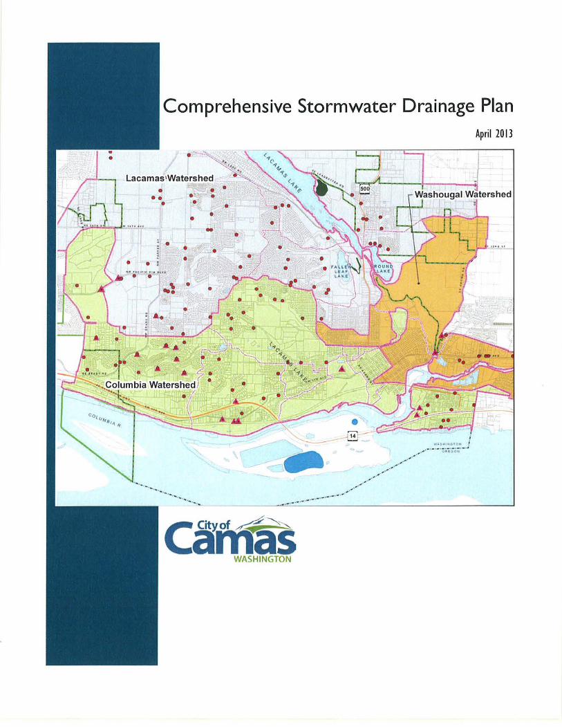
Comprehensive Stormwater Drainage Plan April 2013
WA • w1H 6fOH - ............. / ............... ,.,.,., .. ..
... -. -. -. -·-· -· -· -·-. -· ,.,.-···-·'
can< as WASHINGTON

canTas WASHINGTON
City of Camas
Comprehensive Stormwater Drainage Plan
Submitted to:
City of Camas, Washington
616 NE Fourth Avenue
Camas, WA 98607
Prepared by:
Otak, Inc.
700 Washington Street, Suite 401
Vancouver, WA 98660
Otak Project No.16060
April 2013

Table of Contents
Table of Contents
Abbreviations and Acronyms .................................................................................... v
Section I-Introduction ............................................................................................. 1
1.1 Introduction ................ . . .................................................................................... 1
1.2 Plan Goals ...................... . .... 2
1.3 Previous Studies .................................................................................................................. 5
Section 2-Regulatory Environment ....................................................................... 7
2.1 Introduction .................................................................................................................... 7
2.2 The Clean Water Act (CWJ\) ............................................ .. ················· ................ 7
2.3 The Safe Drinking Water Act (SDWJ\) ........................................................................ 11
2.4 Endangered Species A.ct (ESA) ....................................... . .. ....................... 14
2.5 City of Camas Municipal Code Requirements ... .. ......... 14
2.6 Growth Management Act (GMA) ................................................. . .. ......... 15
2.7 Shoreline Management Act (SMA) .............................. .. .. ......... 16
2.8 State Environmental Policy Act (SEPA) .. .. ........ 16
2.9 Tribal Consultation and Collaboration ........ 17
Section 3-Study Area Characteristics ................................................................ 19
3.1 Introduction ....................................................................................................................... 19
3.2 Study J\rea ........................................................................................................................... 19
3.3 Land Use and Zoning ..................................................................................................... 19
3.4 Physical Characteristics ......... . ............................................................................ 20
3.5 Existing Storm Drainage Systcm ..................................................................................... 22
11
Table of Contents
Continued
Section 4-Study Area Watersheds ..................................................................... 31
4.1 Introduction. ............... 31
4.2 Columbia River Watershed ............................................................................................ 32
4.3 l.aca1nas l.akc \\iatcrshed .................................................................... .. ................... 36
4.4 Washougal River & Lower Lacarnas Creek Watershed ............................................. .40
Section 5-Capital Improvements ........................................................................ 47
5.1 Introduction ..................................................................................................................... .47
Project Na1nc: 'rransportation l(clatcd Storn1\vatcr Facilities ..................... .
Project Na1nc: Storn1 Sc\VCf c:onvcyancc lvfodeling ............ .
Project Na1ne: North I)\vyer C:rcek Stor111\vatcr 13asin Plan .................................... .
. ........ 51
... 53
.55
l)rojcct Na1ne: c;rass \Talley StorlTI\Vatcr 13asin l)lan .............................................................. 57
Project Name: Pacific Rim Boulevard Crossing .............................................. . ............. 59
Project Name: Julia Street Storrnwater Pond Retrofit .................................................... 61
Project Name: Thomas/Carson Estates Flooding .................................................................. 63
Project Name: North Urban Growth J\rea (NUGA) Storrnwater Basin Plan .................... 65
Project Name: Forest Horne Road Sediment Basin ........ .. ............................................ 67
Project Name: Blue Creek Sediment Basin ............................................................................. 69
Section 6-Financing ................................................................................................. 71
6.1 Introduction ..................................................................................................................... 71
Section ?-References ............................................................................................. 73
(_'it} of (-all/({S
\' \l'ltOJH'.T\ l(,(~111\ J(,()(,(1\lkporl> \~tncmw,11cc C.1P"'l lmpr<l\"<"mcnt l'L1n\Dr.tlc Cll' \'<'r ·I.doc><
Appendices
Appendix A: Storm Facilities Maintained by City
Appendix B: Cost Estimates
Appendix C: SEPA
Table of Figures
Table of Contents Continued
Figure 1-1: The Importance of Stormwater Management (Courtesy of Clark County) ........... .4
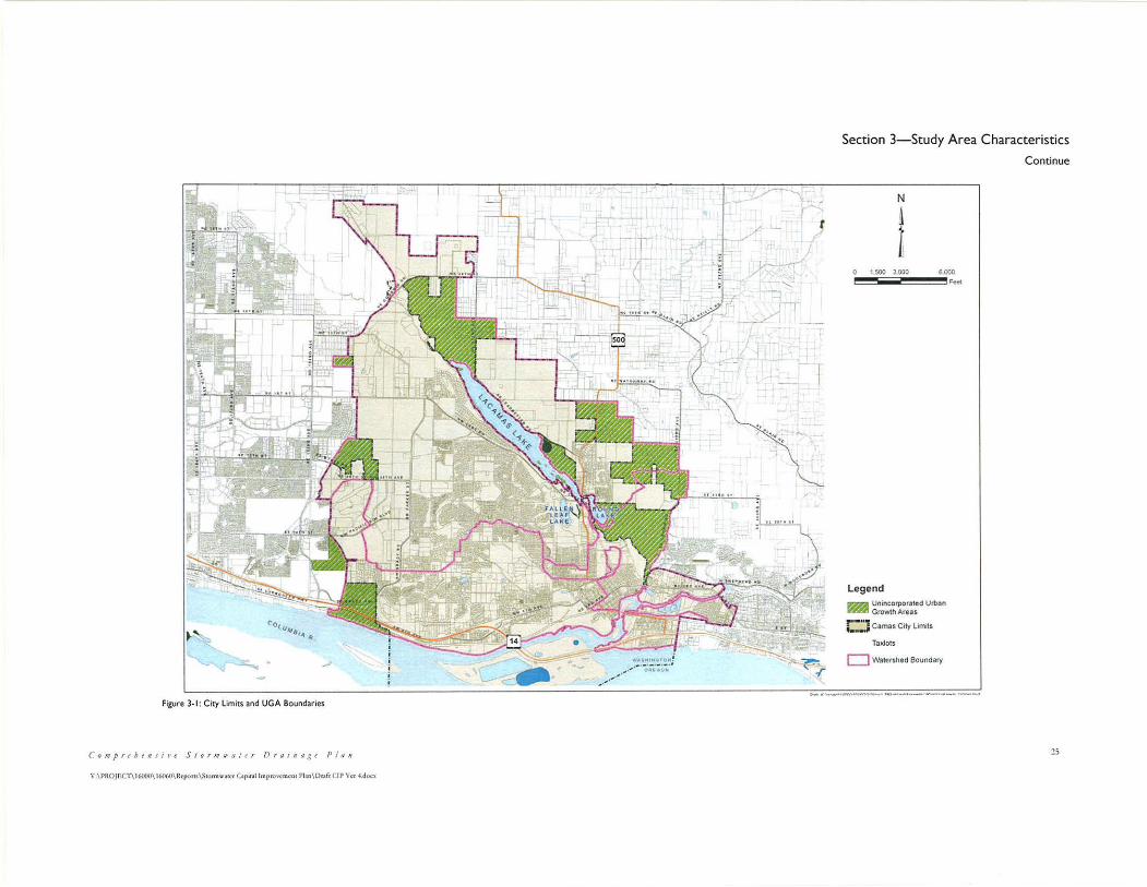
F'igurc 3-1: City l_jinits and UC~J\ Boundaries ............................................................................. 25
Figure 3-2: Current City Zoning ....................... . ·························· ...................................... 26
Figure 3-3: City Contour Map ........................................................................................................ 27
Figure 3-4: NRCS Soil Categories ................................................................................................. 28
Figure 3-5: Environmental Constraints and Unstable Slopes .................................................... 29
Figure 3-6: Watersheds and Basin Boundaries .............................................................................. 30
Figure 4-1: Columbia River Watershed and Basins .................................................................... .43
Figure 4-2: Lacamas Lake Watershed and Basins ............................................... . . ... .44
Figure 4-3: Washougal River & Lacamas Creek Watershed and Basins ........ . . .... .45
Figure 5-1: CIP Project Locations .................................................................................................. .49
Figure 5-3: Julia Street Pond in a spring 2012 flood event .......................................................... 61
Figure 5-4: Sediment collection facility at Blue Creek. ................................................................. 69
(.'on1prehe11si11e Stor111wa!er Drai11age Pla11 111
\'_\l'UOJl'.Cl'\16(HJ0\161)(,(l\lkpom\S1ormw.nl'I' C.1pcl.tl lrnpmv<·mcnt l'l.rn\l)r.1!! CIP V<'t .J doc"

lV
Table of Contents
Continued
Table of Tables
Table 1.1: Past Stormwater and Drainage Studies .... .. .. 5
Table 2.1: Class V Well Identification Guide From EPJ\ .......................................................... 12
Table 3.1: Camas Land Use Zoning ............................................................................ .
Table 4.1: Camas Watersheds and Basins .............................................. ..
Table 4.2: Columbia River Watershed Stonnwatcr Strategics ........................................ .
Table 4.4: Washougal River/Lower Lacamas Creek Watershed Stormwatcr Strategies ........ .41
Table 5.1: Cl!' Summary .... .. .... .47
Table 5.2: Transportation Related Stormwater Facilities Estimate and Funding Plan ........... 52
Table 5.3: Storm Sewer Conveyance Modeling Estimate and Funding Plan............. ...54
Table 5.4: North Dwyer Creek Estimate and Funding Plan.......................................... ..56
Table 5.5: Grass Valley Estimate and Funding Plan .................................................................... 58
Table 5.6: Pacific Rim Boulevard Estimate and Funding Plan .................................... .. .. .... 60
Table 5.7: Julia Street Stormwater Retrofit Estimate and Funding Plan ...................... . .. .... 62
Table 5.8: Thomas/Carson Estates Flooding Estimate and Funding Plan ............................... 63
Table 5.9: NUGA Estimate and Funding Plan ............................................................................ 66
Table 5.11: Forest llome Road Sediment Basin Estimate and Funding Plan ........................... 67
Table 5.12: Blue Creek Sediment Basin Estimate and Funding Plan ......................................... 70
Table 6.1: Stormwater Utility Rates ...... . .................................................................................. 71
("ii)' o_l Ca111as
\'-\1'1\0jl:<:T\ 16000\l(.(l{;l)\R<'J'C>l($\~1omrn·.1t<'f C.iptul lmprMcm<-m l'Lrn\Dr.1fr Cit' \'<·r ·I.doc'
303(d) List
BMP
CI!'
Collection and
conveyance syste1n
C\X/1\
DMA
l)ctcntion
Ecology
EIA
EPA
ESC Plan
Abbreviations and Acronyms
1\n El' A-mandated listing of streams that do not meet water quality standards. It includes the conta1ninant type and source, stream
segment length, and other information.
13est Managc1nent I:>ractice: i\ l-1est IY1anage1nent Practice is an
activity, device, or structure that serves as a incans of reducing or
eli1ninating the generation of pollution or the 1nove1nent of
pollution to\vards strcatn, rivers, and lakes.
Capital Improvement Project or Capital Improvement Plan
1ncans the drainage facilities, both natural and n1an-n1adc, \vhich
collect, contain, and provide for the flo\v of surface and storn1\vater
to a receiving \Vater or infiltration facility. 'I'hc natural elcn1cnts of the conveyance systcn1 include, but arc not li1nitcd to, stnall
drainage courses, streams, rivers, lakes, and \vctlands. T'he human-
1nadc clements of the collection and conveyance systetn include,
but arc not li1nited to, gutters, inlets, ditches, pipes, channels, and
retention/ detention facilities.
Clean Water J\ct
l)esignatcd l\Janagen1ent 1\gcncies
To hold runoff in a basin (pond) for a short period of time, thereby
delaying the introduction of its volun1c (quantity) of storn1watcr to the neighboring streatn.
Washington State Department of Ecology
Effective ltnpervious 1\rea: H .. efcrs to itnpcrvious area that is
directly connected to a collection systcn1, as opposed to running across grass or some other type of pervious systetn before entering
the collection system.
E~nvirontnental Protection J\gency
Endangered Species Act
Erosion and Sediment Control Plan
C:o111preheHsive S1orJJ1111a/er l)raiHa,~e Pla11 v
\":\l'llOJIOC l'\16tX\()\16060\Rq}(Jrt>\Sti>rn\u·.u<'f C.1p<t.il lmprm·cmcnl Pl.m\Dmft C!P \'er ~-don
Vl
Abbreviations and Acronyms Continued
r-:.·1ood c:ontrol Facility J\ detention, retention or other storage facility that reduces the f1o\V
rate of stor1n\vatcr runoff and retains and releases storage volu1nes.
r;lood l)lain 'I'he land bordering a strea1n subject to inundation when the strcan1
is at flood stage.
Flow Control Exempt Large water bodies shown in Appendix l-E of the 2012 Stormwatcr lvfanagc1ncnt Manual for \V'cstcrn \Xlashington arc cxe1npt fron1
1Vfini1nu1n H.equirc1ncnt 7.
FrE Full-time Equivalent Employee
Cround Water The water under the surface of the earth that is found within the pore spaces and cracks bct\vecn the particles of soil, sand, gravel
and bedrock.
I--Iydraulic c:onncctivity Si1nilar to r_;J;\, \vherc runoff fro1n itnpervious surfaces arc directly
connected to a collection syste1n. !\.educing I--Iydraulic connectivity
refers to discharging stor1n\vater to pcrvious areas rather than a
collection systen1.
IDDE
Illicit Discharges
Injection Well
LEED
LID
MS4
NFII'
Nl'AFS
NOAA
Illicit Discharge and Detection Elimination Program
1\ny discharge to a storm SC'\VCr that is not co1nposed entirely of
stormwater and is not allowed per the NPDES permit and C.M.C. 14.04
fvfcans a '\-vcll" into \Vhich "fluids)' arc being injected.
1~cadership in I~nergy and l~nviron1ncntal l)esign.
l,O\V 11npact 1)evelop1nent
Municipal Separate Storm Sewer System: The Municipal Separate Stor1n Sewer Systcn1 is an Ii.l)1\-1nandatcd progra1n that requires
1nunicipalitics to initiate activities to reduce its quantity and
itnprovc its quality of stormwatcr.
National Flood Insurance Program
National IV1arinc f<ishcries Services
National Oceanic and 1\ttnospheric 1\dnllnistration
('it)' o.f c·a111as
NPDES
NRCS
Non-Point Source
NUGA
Non-Structural BMP
O&M
IJoint Source
SDC
SEPA
SFl·L\
SMlV!\Xl\XI
Storn1 Sc,vcr
Stortn\vatcr
Structural BMP
Surface Water
SWMP
Abbreviations and Acronyms Continued
National Pollutant Discharge Elimination System: A permit
required from I~P J\ for the discharge of stortn\vatcr into rivers,
streams, and lakes. It is the pcrrnit that governs the activities under
the MS4 program.
Natural H.csourcc Conservation Service
Water pollution that does not come from a specific pipe, but is derived from storm\vater runoff and flo\vS to streams, rivers, and
lakes directly from adjacent properties.
North Urban Gro\vth J\rea
J\ BMP that does not include the use of a structural device, such as
public education.
()pcrations and Maintenance
\Xlater pollution that is released fron1 a specific pipe into a strean1,
river, or lake.
System Development Charges
State Environmental Policy Act
Special Flood Hazard Areas
'l'hc 2012 Stortn\vater lv1anagctncnt ivfanual for \Xlestcrn
Washington, prepared by the Washington State Department of Ecology.
i\ syste1n of belo\v-ground pipes that convey storn1\vatcr to its
discharge point.
Stor1n\vater is rain\vatcr that accu1nulates on land as a result of
storms and runoff fron1 urban areas such as roads and roofs.
1\ l3JvlP that involves the use of a structure, such as a vegetated
filter strip or catch basin with sump.
Surface water includes stortn\vater, and \Vater in a strcatn, river,
lake, \vetland, or ocean.
Storn1\vater Master l)lan
Co1JJjJreheJ1si1Je Stor1JJwa!er l)raiJJage P/011 vu
\".\l'l\OJ10Cf\l6l\0(l\!(,{)(,(l\)tq1m1>\~1<>nnw.lk1 Ctp<UI Jmpro\"enwm l'l.H1\Dc,dt Cll' \"<·•·!doc'
Vlll
Abbreviations and Acronyms Continued
SWPPP
TMDL
TSS
UIC
Waters of the State
\VLJ\
WQ
Storn1\vater Pollution Prevention Plan
Total Maximum Daily Load: Total maximum daily load is a n1easure1nent of the 1naxi1nu1n concentration of a specific
conta1ninant possible in strea1n v.ratcr without causing harn1 to the
stream.
Total Suspended Solids
Underground Injection c=ontrol: 1neans the lJndcrground Injection
Control program under Part C of the Safe Drinking Water Act, \vhich regulates injection \vells.
Includes those \Vaters as defined as '\vaters of the United States" in
40 CFR Subpart 122.2 within the geographic boundaries of \Xfashington State and '\vaters of the State" as defined in (]1apter
90.48 l:ZC\'\.1, \Vhich includes lakes rivers, ponds, strca1ns, inland
waters, underground \Vaters, salt \Vaters, and all other surface waters
and water courses within the jurisdiction of the State of
Washington.
Wastcload Allocation
Water Quality
C'i!J o_/ Ct1111as
\. \l'll0JECT\!61)(J(I\ l(oOl11J\Hqwn;.\~"'rrn\\\l1<"r Cop•UI lmp«J\·r•11>r·m l'lln\Dr.•f< CJI' \',•,--!.de''"
Section I-Introduction
I. I Introduction
i\s \vi th many communities across the country, the City of Camas is facing the challenge
of balancing growth and development with quality of life and environmental
ste\vardship. H .. ecent infonnation regarding the itnpact of urban storm\vater on the
environ1nent has pro1npted nc\v regulations, including National Pollutant Discharge
Elimination System (NPDES) permitting, Underground Injection Control (UIC)
regulations, and the Endangered Species Act (ESi\). These regulations have forced
jurisdictions to fund ever-expanding stor1nwater progran1s. J\nd, the i1nplcn1cntation of
water quality and flo\v control regulations finds jurisdictions \Vith a need to tnanagc and
1naintain an ever larger list of storn1water infrastructure cotnponents.
J\s "'vith all utilities, stotm\vatcr infrastructure requires routine inspection and
maintenance. Sc)lne pipelines in the do\vnto\vn core are well over 70-years old, and
repairs bcco1ne 1nore frequent to properly 1naintain these assets. Some stor1nwater
facilities such as detention ponds and biofiltration S\Vales have been in place for 20 years
or n1ore, and these facilities require routine 1naintenance and repairs such as re-grading
and landscaping, fencing replace1ncnts, access road upkeep, or structural repairs.
The City's NPDES stormwater discharge permit with the Washington State Department
of F~cology (I:<:cology) continues to consume tnore of the C:ity's resources. H .. etrofit
programs, monitoring, mapping, record-keeping and reporting, illicit discharge and
detection, public education and outreach, and the 1nyriad of other require1nents takes
1nore staff titne and requires 1norc capital projects to stay in co1npliance.
'I'he current storn1\vater utility rate docs not include a large capital. F'inancial C:onsulting
Solutions Group (FCSG) conducted a rate study in 2009, and this study set the storm
rate to recover the cost of basic operation and 1naintcnance of the existing stor1n syste1n
and 1nodest amounts for rcplace1nent of existing infrastructure. J\s part of the I-~'isher
Basin Utility, some capital dollars have been available but that account has been
depleted. To provide a secure long term capital fund, the FSCG study proposed
implementation of a System Development Charge (SDC) with a methodology consistent \vith the current \Vater and sc,ver Sl)C. 'I'he rate \vould capture both historical costs and
future capital needs. Prior to considering an SDC the City is required to adopt a basis for
the SDC:.
F•'or these reasons and others, the C:ity proposes to develop a stormwater capital
in1prove1nent program si1nilar to those for their transportation, water, and wastewater
systems. These well-established programs arc used for developing, implementing, and
funding projects necessary for the ongoing niaintenance, repair, and upgrade of existing
assets, and for the planning and construction of new facilities. This plan will provide the
basis for the future capital component of a SDC:.
C'or11j)rehe11si1Je Stor1J1111ater J)rai11a<~e P/011
2
Section I-Introduction
Continued
This inaugural CIP provides a capital program list that can be used to plan and fund
stortn\vater 1naintenance activities, retrofits, repairs, and ne\v facilities to serve existing
and ne\v dcvclop1ncnt. 'This list can be used to develop a six-year capital plan sin1ilar to
other city infrastructure prograrns. 'l'he intent of this inaugural plan is to identify an
initial list of maintenance and capital i1nprove1nent projects necessary to adequately care
for the city's stor1nwatcr infrastructure. 'rhis plan includes the following co1nponcnts:
Section 'I\vo: J\ discussion of stonnwatcr regulations that the city follov..1s.
Section Three: A discussion of the study area (City limits plus urban growth area)
characteristics that influence stortnwatcr 1nanagen1ent.
Section 1-=-·our: i\ discussion of future dcvclopn1ent potential and how the c:ity's
stonn\vater ordinance 1nay be 1nct with the future developn1cnt.
• Section r~ive: 1\ list of capital projects identified for correcting deficiencies \Vi th
existing facilities or identifying future capital i1nproven1ent needs.
Section Six: r\ description of the City's storn1\vater funding through their
stonn\vater utility. F'uture editions to this plan \vill include a plan to tncct the
City's ongoing funding needs for stor111\vater infrastructure.
1.2 Plan Goals
The City has initiated the development of a Capital Improvement Plan as part of their
structured approach for itnplc1ncnting stortnwater progratns and projects, and
n1aintaining the C:ity's existing storn1water assets. 'rhis plan seeks to align itself \Vith and
ascribe to the goals of the City's nlission statcn1cnt:
T'/Je C/1)1 of (J0111as co111111its to preserviJ~g its he1ita,ge1 s11staining and enhanli11g a high qua!i(J' ef life far all its citizens a11d developi11g the co111t111111il)' lo llleel the challenges of the.f11t1m. 117e take pride 111 preservi1~g a healthji1! t'11viro111J1e11t Jvhile proJJ1oti11g eco1101JJic~€'v1vlh. IP'e e11co11ragl' cl-lizens to pa1ticipat1? in gover111JJe11t a11d co111JJ1u11i(y, assirtin,__g the ci(y in its efflJJts to p1vvide quali(y services co!lsistent 1vith their desin:s and 11eedr.
'rhis n1ission statctncnt describes the City's con1111itn1ent to protecting the environ1nent
and quality of life for its citizens, \vhile pro1noting ccono1nic dcvelopn1cnt to n1aintain
vitality in the urban area. With that in mind, the following goals have been developed for
this stonn\vater capital progratn:
C:reatc a progran1 for StOrlll\Vater tnanagetncnt that replicates capital progratns
for the C:ity's Other infrastructure systems and alJO\VS for capital progran1
planning and funding.
Develop a program that allows for adequate funding of stormwater projects that
supports the c:ity's transportation infrastructure progratn.
('if)' of ('(JIJ/OS
\·_\\'ltOJH:T\!6()(l{l\!(J()(,(l\ltq>or(i\~wnm\'.orcr Cap1!.ll lmr><o,·<·m<'"1 Pl.•n\Dr.llt C!I' \"c1 ·!.dnc'
Section I - Introduction Continued
Provide storn1watcr managcn1cnt in a way that is consistent with the City's
1nission staten1ent in regard to environtnental protection and ccono1nic
dcvclop1nent.
I~'igure 1-1 provides a discussion of stor1n\vater runoff and ho\v land use affects both the
quantity and quality of the runoff ;-\s this water is '\vhat feeds our creeks and streams, it
has a direct affect on the quality of aquatic habitat. This discussion provides information
on the frarnc\vork from '\Vhich stortn\vater 1nanagcment tools are developed.
C'o111prehe11sive S1or1J1waler Drai11age Pla11
\'-\l'ltOJIOCT\ !MXl!l\16("",0\ltqioo•> \~10rmw.HN Copu.11 !rnpr<n'('f\\<'otf 1'),1n\l)r.,f1 CIP \'er ·I.doc'
3

Section I-Introduction
Continued
The Importance of Sto rmwater Management
The Water Cycle The eorth's worer continuously circulates between the atmosphere to the land in the fo1ms of e'IOpotronspiJOlion (from eorlh lo atmosphere) ond rainfall where it becomes surface woter ond infillTotes into the son to become g1oundwoter. !his is coiled the water cyde, or hydrologic cyde, ond is key to understanding sto1mwate1 impacts.
In natural (undeveloped) conditions, 1oinfoll infiltJOtes slowly into tl1e ground. Notu1ol biologic processes cleanse the water os it moves through vegetation ond soil and into g1oundwoter. Berouse most 10insto1ms 01e not lo1ge enough to ful~ saturate the soil, only o small pe1cen1oge of roinwote1 flol'IS over tlie surface os 1unoff. What does become runoff usual~ lrol'els in o slow, meandering pace. Portides ond sediments settle out along the way, ridding the wote1 of impurities before ii flows into rivers ond stream\.
The Effects of Development Development drosticolly olte1s port of the natural water cyde. Impervious surloces such os buildings ond 10ods prevent rain from soaking into the ground. There is also less vegetation to soak up, store, ond e'IOpo1ote water. In addition, the natural soil structu1e is lost os o 1esult of grading ond compaction during constrnction. As o result, stormwoter 1unoff g1eotly inaeoses, flowing over land surfaces 01 through conveyance systems (such os pipes ond ditches) into 1ivers ond streams. !hrs olterotion of the woter cyde con hove significant negative effects on surface wote1 ond groundwater, causing harm to fish ond wildlife, drinking water supplies, property, recreation, ond other beneficial uses. • lncreosed runoff volume ond speed moy cause flooding ond eros.~n ond impairment
of noturol hobitot in rivers ond sireoms. • Because less wote1 infilnotes into the ground, less groundwater recharge may occur.
This con reduce drinking water ond irrigation supplies ond moy also reduce bose flows irr streoms, which run be dellimentol to fisl1 and aquatic organisms.
• Developed surfaces retoin heot, which inoeoses runoff temperature during worm weather. This rn turn moy raise the temperature of the 1eceMng waters, with potential negative impacts on oquolic life.
• SI01mwo1e1 runoff picks up oil, fertilizers, pesticides, metals, chemicals, sediments, bacteria, debris, and othe1 pollutants ond may corry them into 1iversond streoms.
Mitigation through Stormwater M anagement Stormwote1 management goofs me intended to mitigate sro1mwoter impacts creored by typirol development p1octices so new development and 1edevelopment maintain o bette1 balance with the noturol worer cyde. This is achieved through the following opp1oaches. • SouJCe conlTol best
management p1octices (BMPs) p1event stom1wote1 horn coming into contact with pollutants in the fast place. Examples indude sweeping instead of using wote1 to doon on outdoo1 meo and minimizing the use of chemicals fo1 yo1d ro1e. SouJCe contJOI BMPs 01e o cost-effective moons of 1edudng pollutants in stormwote1 and should be o !ilst conside1ation in all p1ojects.
• T1eotment BMPs 1educe pollutant loads and concentrations in sta1mwoter 1unoff th1ough physirol, biological, and diemirol removal mediomsms. Examples mdude biofiltrolion, dispe1sion. constwcted wellonds, and p1op1ietory filte1 systems. These BMPs may accomplish signifiront levels of pollutant food 1eductions if p1ope1~ designed and maintained.
• Flow cont1ol BMPs detain, 10toin, 01 infiltrate st01mwote1 1unoff to control rhe flow 1ote, flequency, durntion, and volume of 1unoff leaving the site. Examples include detention ponds, infiltrotion systems, and constructed wetlands.
• Low impact development opp1ooches emphasize roptu1ing, t1 ooting, and infiltrnting sto1mwote1 al the source. Techniques me used that mimic notu1ol p1ocesses by allowing sto1mwote1 to slow~ soak into the g1ound 01 filte1 th1ough l'egeto· tion-fo1 example, po1ous pavement, rnin ga1dens, infilllotion plonte1s, and green 1oofs. Design and construction methods that pieseive and toke odvontoge of the site's noturnl feotu1es, such as open spaces, native vegetation, notu1ol dep1essions, and wetlands Ole olso conside1ed LIDA. This approodi provides mulliple envi1onmen1ol, aesthetic, ond cost benefits in addition to sto1mvrote1 management.
Figure 1-1: The Importance of Stormwater Management (Courtesy of Clark County)
4 Cit)' of C a1J1a s
V:\ PROJEC J'\16000\16060\Rtports\Stonnw.:tlCr Cap1r.tl I mprovement Plan\DrAft Cit> Ver -4.docx
1.3 Previous Studies
Section I - Introduction Continued
The City has conducted stormwater studies to address specific problems or to provide 1nastcr plans for specific areas. rfhis Capital In1prove1ncnt Plan includes a rcvie\v of these
past reports to identify opportunities for implementing projects developed with those
studies. The key plans and studies are listed in Table 1.1.
Table I. I: Past Stormwater and Drainage Studies
Date
Study Name (City Job No.) Published Author
Fisher Basin Sub-area Plan (S-253) Early 1990's Parametrix, Inc.
North Dwyer Creek Master Plan (S-370) October 1998 David Evans and Associates
Technical Memorandum for Long-Term February 2001
David Evans and Assessment of North Dwyer Creek ( S-370) Associates
Fisher Basin Stormwater and Wetlands July 2001
David Evans and Master Plan, Phase 1 (S-370) Associates
Lacamas Lake: Nutrient Loading and In-April 2004 Clark County
lake Conditions (NA)
Fisher Basin Hydrologic and Hydraulic October 2005 Maul, Foster, and Alongi
Analysis (S-456)
Monitoring Report Lacamas Lake Annual 2007 Clark County
Date Summary for 2007(NA)
('0111prehe11sive Stor1JJwater J)rai11a,ge P/011 5
Section 2-Regulatory Environment
2.1 Introduction
The City of Camas is required to meet local, state and federal regulations applicable to its operations and activities. Environmental regulations that apply to the City arc su1n1narizcd in this section. While the primary focus of this CIP is stonnwater, the impacted natural resources include surface \\raters and associated aquatic species and habitat as well as groundwater.
'l'his section provides a description of each requirement \vith the 1najotity of the narrative
focusing on those regulations dee1ned to be the primary drivers that 1nost influence C:ity
functions. I3ccausc it is a tcgulation that spans 1nultiplc cnvironn1ental tnedia, the State I~nvironn1cntal l)olicy 1\ct (SI~P 1\) is covered as an adjunct to other cnvirontnental regulations. Similar to SEPA, tribal input through the consultation and collaboration process spans multiple regulation and cnvironn1ental 1nedia and is also an adjunct to the other listed
regulations. C:onscqucntly, these t\vo topics are treated separately and arc discussed at the conclusion of this section.
2.2 The Clean Water Act (CWA)
The CWA is the primary federal law governing water pollution. The goal of the CWA is to clitninatc releases of pollution into water and ensure that surface waters 1neet standards to
protect fish, shellfish, wildlife and human health. Under the CWA, EPA has implemented pollution control programs including the National Pollutant Discharge Elimination System (NPDES) permit system which applies to industrial, municipal, and construction discharges to surface \Vaters. In \\!ashington State, r~p i\ has delegated authority to adnllnistcr the
NDPES permit program to the Washington State Department of E'.cology (Ecology). The NPDES Phase II Municipal Stormwater Permit applies to the City of Camas.
The CWA also regulates quality standards for surface waters and requires that water bodies
not meeting standards be placed on the CWA section 303(d) list. Waters placed on the 303(d) list require the development of a water cleanup plan, also known as a Total Maximum Daily Load (TMDL). Following the issuance of a TMDL, NPDES permits are modified to include implementation of requirements to reduce pollutant loading.
The NPDES stormwater permit, standards, the 303(d) list and TMDLs and their applicability to the City are further described in the following sections.
Co1J1prebe11sive Stor1JJ1JJt1/er IJraina~~e Pla11
\'·\l'lt0JF.C'r\l6000\!60(,l)\lkpom\.'.10rn1w.u<·r C.1p1ul lmprowrncm l'Lrn\Dr.<f1 Cl!' \'~r ·Ldoc.'
7
8
Section 2-Regulatory Environment
Continued
2.2.1 NPDES Permit Description and Applicability
Phase 11 NPDES Municipal Stormwater Permit
NPDES Phase II permits, first issued in 1999, requires regulated small Municipal Separate
Storm Sewer Systems (MS4s) in urbanized areas, as well as small MS4s outside the urbanized
areas that are designated by the permitting authority, to obtain NPDES permit coverage for
their storn1water discharges. Small IV1S4s are jurisdictions or agencies with populations under
100,000 that arc not regulated by a Phase I program.
Small MS4s outside of a UA arc required to obtain an NPDES permit if it is serving a
jurisdiction with a population of at least 10,000 and a population density of at least 1,000
people per square n1ilc.
I~ach regulated lvfS4 is required to develop and itnplcn1ent a storn1watcr 1nanage1nent
program (SWMP) to reduce the contamination of stormwatcr runoff and prohibit illicit
discharges.
J\n MS4 is a conveyance or systc1n of conveyances that is:
•
•
•
()wncd by a state, city, town, village, or other public entity that discharges to \Vatcrs
of the U.S.;
Desigi1cd or used to collect or convey stor111\vatcr (including stor1n drains, pipes,
ditches, etc.);
Not a con1bincd sewer; and
Not part of a Publicly Owned Treatment Works (sewage treatment plant).
NPDl~S l)ertnit tenns run for five years. rfhe current 1\!funicipal pcrni.it \Vas issued January
17, 2007, went into effect on February 16, 2007, was modified onjune 12, 2009, and expired
on F'ebruary 15, 2012. J\ draft pern1it for the next pcrn1it tern1 is currently undergoing
review, and l~cology has extended coverage for the existing pcnnit until the nc\.V pcr1nit is
reissued.
In1ple1nenting the City's NPI)I~S pcrn1it requires a C:o1nprehcnsive Stortn\vater I\1anagcn1ent
l)rogratn that includes:
•
•
•
Mapping stor1n\vatcr syste1ns
Educating employees and the public
Detecting and eliminating illicit discharges
Controlling storn1\vatcr runoff from new dcvclop1nent, redevelop1nent and
construction
Ci!J of c-a111rts
\":\PltOJl'.Cr\l(,(~lO\l(ol'(,(l\Rrpmt>\:;wm1w.ucr Cap"·'i lmprn1·enwnr l'l,,n\Dr.•ft Cll' \·er .J.doc'

Section 2-Regulatory Environment
Continued
1\11 operations and 1naintcnance progratn
;\nnual reporting
N PDES Stormwater Permit - Construction General
The NPDES Construction Stormwatcr General Permit was originally issued in 1995 and regulated sites with greater than five acres of disturbance. It was re-issued by Ecology Novc1nbcr 16, 2005, \vhcrc coverage changed from 5 acres do\vn to one acre and reissued
again on December 10, 2010.
In general, the permit regulates clearing, grading and/ or excavation that results in the disturbance of one acre or 1nore for sites that discharge stortn\vatcr to surface \Vatcts of the
state. In some cases, s1naller sites may be subject to the per1nit if I2cology deter1nines the site
to be a significant contributor of pollutants or expects discharges from the site could reasonably cause a violation of \Vatcr quality standards.
'T'he rcquire1ncnts of the c:onstruction c;cneral l)ennit include:
•
•
Compliance with applicable state water quality and sediment management standards
Monitoring H .. cquiremcnts
Reporting and Recordkeeping
Solid and Liquid Waste Disposal
Additional Restrictions for Discharges to 303(d) listed or TMDL Water bodies
Stormwater Pollution Prevention Plan (SWPPP)
'fhe pcrtnit requires monitoring for turbidity and in certain cases for pl-I. \Xlhcn bcnchn1ark
values for these constituents arc exceeded, the S\\fIJPI) must be revised as needed, source
control and treattncnt 13MPs must be in1plementcd, and all activities docutncntcd in the site
log book. In addition, Ecology must be notified by phone and daily sampling continued until constituent levels are reduced to acceptable levels. J\ny discharges to TMDL or 303(d)-listed waters that exceed numerical effluent limits for turbidity and pH constitute a violation of the pcr1nit.
The Construction Permit applies to:
• land disturbing operations that disturb one or 1nore acres, or
Sites that are part of a larger common plan of development or sale that disturb less than one acre of total land area if the larger common plan will ultimately disturb one or 1norc acres.
CoN1prehe11sive Stor111n1a/er l)rai11age P/011 9
10
Section 2-Regulatory Environment
Continued
2.2.2 303(d) List and TMDLs
303(d) List
Under Section 303(d) of the CWA, states are required to prepare a list of surface waters
\vhcrc beneficial uses have been iinpaircd. 1'hese beneficial uses include industrial use,
aquatic habitat, drinking \Vatcr, and recreation. In \Xlashington State, Ei.cology conducts biennial \Vater quality assess1nents to detennine \vhether surface \Vatcrs are n1ecting state
surface \\rater quality standards. Ecology's assess1ncnt of \vhich surface waters are placed on
the 303(d) list is guided by federal laws, state water quality standards, and the Policy on the
Washington State Water Quality Assessment. This water quality policy describes how the
standards are applied, requirements for the data used, and how to prioritize TMDLs. The
goal of the policy is to provide a guide for selecting which surface water is impaired by
pollutants and how severely.
The 303(d) List represents polluted waters that require the development of a water quality
improvement project or TMDL. A TMDL is the amount of pollutant loading that a given
\Vater body can receive and still 1ncct \Vatcr quality standards established. to protect beneficial
uses.
The Environmental Protection Agency (EPA) approved Washington's current water quality
assessment and 303(d) list on January 29, 2009. In Camas, the water bodies and constituents
include the following:
Lacamas Creek (dissolved oxygen, temperature, bacteria and pH)
Lacamas Lake (total phosphorous)
• Washougal River (fecal coliform)
Dwyer Creek (dissolved oxygen)
Lower Columbia River (temperature, total dissolved gas, dioxin)
Ecology expects to submit a new Freshwater 1\ssessment and 303( d) list to the EPA for
approval during the winter of 2012-2013.
TMDLs
Currently, the City has not been identified as a party with implementation responsibilities
under any existing TMDLs. A new TMDL is currently under development by Ecology
associated with the listings for Lacamas Creek on the current 303(d) List. Ecology's TMDL
prioritization and scheduling process is a five-step, five-year process that includes public
notice, public involvctnent, scoping, data collection and analysis, action plan development
and i1nplen1cntation. In1plementation rcquircn1cnts arc included in NPDES waste discharge
pcr1nits when issued or through pcr1nit 1nodifications.
c· i lj o.f ca !JI(/ s
Section 2-Regulatory Environment
Continued
Under RCW 90.48 - Water Pollution Control, and in the absence of an established TMDL,
I~cology has the authority to condition the c:onstruction Storm\vater General l)crmit \Vith
additional requirements to control discharge of pollutants to impaired water bodies listed on
the 303( d) list.
2.3 The Safe Drinking Water Act (SDWA)
The SDWJ\ is the primary federal law governing protection of drinking water and applies to
all public water systems. Under the SDWA, the EPA has established National Primaty
l)rinking \Xlater l\.cgulations that set standards for 1naxi1num contan1inant levels to ensure
drinking water quality. The SDW/1 also authorizes the EPA to regulate injection wells to
protect underground drinking \Vatcr supplies.
2.3. I Underground Injection Control (UIC) Rule
T'o satisfy the intent and rcquirc1ncnts of the Sl)Wi\ and the \\/ashington State \Vater
Pollution Control Act, chapter 90.48 RC:W, the Washington State Legislature adopted the
UIC Program, chapter 173-218 WAC. Under this program U!Cs used for stormwater
discharge and/or treatment arc considered Class V U!Cs.
Class V injection wells are usually shallow injection wells that inject fluids above the
upper1nost groundwater aquifer. Some exa1nplcs include dry \vells, french drains used to manage stormwater, and drain fields. Examples of Class V injection wells that arc allowed in
\\7ashington, and relate to stormwater, include drywells and infiltTation trenches used to
drain storn1water runoff into the ground surface.
All Class V injection wells must be registered with Ecology, except wells receiving residential
roof runoff from a single family home or to control basement flooding at single family
hon1CS (including duplexes). rfhcsc \VCllS arc CXen1pt from the registration require1nents.
'I'o provide clarification on \vhich storn1\vatcr infiltration techniques ineet the (]ass \7 \vell
definition, the Department of Ecology's UIC: website includes a memorandum from the
EPA which identifies specific infiltration practices/technologies and discusses whether at:
not they arc constitute a Class V well (Boornazian, & Heare, 2008). The guidance
infor1nation provided in the J~IJi\ 1ne1norandu1n is sum1narized in 'I'able 2.1.
('01J1pl'rhe11sive Stol'1JJJJ1ater Drai11r1,ge Plan 11

12
Section 2-Regulatory Environment
Continued
Table 2.1: Class V Well Identification Guide From EPA
Infiltration Practice /Technology Considered a Class V Well?
Rain Gardens & Bioretention Facilities No.
Vegetated Swales No.
Pocket Wetlands & Stormwater Wetlands No.
Vegetated Landscaping No.
Vegetated Buffers No.
Tree Boxes & Planter Boxes No.
Permeable Pavement No.
Reforestation No.
No - typically these are downspouts are Downspout Disconnection redirected from sewers to permeable surfaces
where runoff can infiltrate.
Yes - when they include an assemblage of Infiltration Trenches perforated pipes, or are deeper than their
widest surface dimension.
Commercially Manufactured Stormwater Yes.- typically these constitute a subsurface Infiltration Devices fluid distribution system.
Drywells, Seepage Pits, Improved Yes - typically these are deeper than their Sinkholes widest surface dimension.
The governing EP 1\ criteria used to make the determinations in Table 2.1 includes:
1\ Class \T has a sub-surface distribution systen1
A Class V well is a hole that is deeper than its widest surface dimension
Jf either one of these criteria apply to a particular stor1n\vater infiltration practice or
technology, then it would be considered a Class V well and would be subject to UIC regulations.
The following summary from Ecology's December 2006 G11ida11ce for UJC Wells that Manage Sto11111vater speaks to the requiren1ents for existing UIC wells and rcquire1nents for municipalities with NPDES stormwater permits.
C'if)' o_/ C~aN1as
\'·\l'ROJIOCT\161){)0\ 11•060\ltqwrt>\:'wnnw,,.t·r C1pu.1l lmpw,·enwm l'l.rn\lk•ff C!i' \'<·r ·!don
Section 2-Regulatory Environment
Continued
Existing UIC Wells
UIC wells constructed before February 3, 2006 arc considered by Ecology to be "existing"
\vells and have different rcquireinents than wells constructed after.
Existing UIC wells must be registered with Ecology, except for wells receiving residential
roof runoff from a single family home or to control basement flooding at single family
homes (including duplexes).
J\n asscss1ncnt of existing \vclls n1ust be co1nplctcd to determine if the existing UIC: \vclls arc
a high threat to ground water. UIC wells that arc high threat to ground water must be
retrofitted to protect ground water quality.
New UIC Wells
UIC: wells constructed after February 3, 2006 arc considered by Ecology to be "new" wells
and 1nust 1ncct I~cology's Non-endangern1cnt standard. 'I'his can be done through the
presumptive approach (following the guidelines in Ecology 2006, or through the dc1nonstrativc approach, \vherc evidence is provided that the non-endangcr1ncnt standard is
met.
Requirements for Municipalities with NPDES Stormwater Permits
Municipalities that arc under an Nl)DI~S stormwater per1nit may also have stortnwater
discharges to U!C: wells. The Stormwatcr Management Program required by the NPDES
stortn'\vater permit includes best manage1nent practices that also 1nay be applied to
StOflTI'\Vater discharges to Ul(= wells. 1~o avoid duplication, municipalities that are under an
NPDES stormwater permit may meet UIC program requirements by applying their Stormwater Management Program to areas served by UIC wells. See Chapter 173-218-090(2) W1\C.
Since the NPDES permit does not fulfill all the requirements of the UIC Program, the
following must be added to the Stormwater Management Program (S\VMP) and
implemented:
• UIC: wells must be registered
•
•
New UIC wells must be constructed according to the specifications in this guidance
1\ well assessment must be completed for all existing UIC wells
• Existing UIC wells that arc determined to be a high threat to ground water must be retrofitted
More information on these procedures can be found in Ecology (2006).
Co!!1prehe11sive Stor1J11J1a!er Drai11a~~e Pla11
\'·\l'l<OJl·:CI"\ J(,(l(l(l\ 16060\lkpon;\~rorrl\w.ttn C:lpn:il lmprn'"'"""'"' l'l.rn\Dr.1ft Cll' \·er -!.dr>e'
13
14
Section 2-Regulatory Environment
Continued
2.4 Endangered Species Act (ESA)
The purpose of the federal FSA is to protect species and the ecosystems upon which they
depend. Two primary goals of the ES1\ arc to prevent the extinction of endangered plant and ani1nal life and their critjcal habitats, and to pursue survival and recovery of these
populations. It is administered by two agencies, the U.S. Fish and Wildlife (USFWS)
(freshwater fish and all other species) and the National Oceanic and Atmospheric
Administration (N01\A) (marine species). The ESA prohibits any "take" of species listed as endangered. "'fake" is defined as to harass, har1n, pursue, hunt, shoot, \vound, kill, trap,
capture, or collect. In 1999, 12 groups of Pacific Northwest salmon and several populations
of bull trout were listed as threatened or endangered under the ESA, and in July 2000,
N01\A NMFS adopted a rule governing the "take" of 14 groups of salmon and steelhead listed as threatened under the ESJ\.
Salmon Recovery
The ES1\ and Washington State law require development of plans to recover salmon. The (;ovcrnor's Sahnon llccovcry ()fficc \Vas established by the I~cgislaturc to coordinate a
statc\vide saln1on recovery strategy.
The Lower Columbia Fish Recovery Board (LCFRB) is charged with coordinating salmon
recovery in the lower Columbia River basin, including Camas. They have developed and docu1ncnted a plan to support sahnon recovery for \Xlillatnette/I~o\ver Colun1bia llivcr
Evolutionary Significant Units (ESU) in Washington.
'l'he City of Ca1nas, along with other 1nen1bers of the I)lanning Unit, unanin1ously approved
the plan developed by the LC:FRB on December 13, 2004. The Watershed Management Plan
\Vas adopted by the parent counties of Clark, C:owlitz and Skan1ania counties on July 21,
2006. Detailed implementation planning was completed in June of 2008. Each in1plcn1cnting entity docun1cnts its co1nn1itn1ent and approach to i111plen1cnting specific
actions in its Six-Year I1nple1nentation \Vork Schedule that addresses recovery plan and
watershed plan actions. C:a1nas is currently in1plcn1cnting actions and tracking its activities in a web-based data system called Salmon PORT accessed from the LC:FRB website.
2.5 City of Camas Municipal Code Requirements
There are currently five sections of the City of Camas Municipal Code (CMC) that pertain to
storn1watcr n1anage1ncnt and pollution prevention: Stor111water Drainage Utility, CIVfC= 13.88; Stormwater Utility Service Charges, CMC 13.89; Stormwater Control, Cl'AC: 14.02; Illicit
Discharge. Dumping and Illicit Connections, CMC 14.04; and Erosion and Sediment
Control, CMC 14.06. These ordinances are discussed in detail below.
(.-if)' o.l (-a111as
Section 2-Regulatory Environment
Continued
CMC Chapter 14.02 - Stormwater Control
'l'his chapter applies to ne\v dcvclop1nent and rcdevelop1nent and includes rcquirc111cnts that address the following topics:
•
•
Ileducing and preventing storn1\vatcr pollution during construction
Reducing the introduction of pollutants into surface water runoff
• Installing flow control and/ or stortn\vatcr trcat1nent facilities} depending on size and
the character of the project, and implementing low impact development practices
'l'his chapter also sets 1nini1nu1n standards consistent \vith Ecology's Stor1n\vatcr
Management Manual for Western Washington as modified by the City's Stormwater Design
Standards Manual.
CMC 14.04 Illicit Discharges, Dumping and Illicit Connections
This chapter applies to all new and existing development, public and private. It defines
prohibited, allo'\vablc, and conditional discharges to the 1nunicipal stortn drain syste1n,
and/ or surface and ground \Vatcrs. It further prohibits illicit connections to the 1nunicipal stor1n drain systc1n.
CMC 14.06 Erosion and Sediment Control
This chapter applies to any person undertaking any land-disturbing activity, with the
exception of small parcel development which is regulated under the small parcel
requirements of Chapter 3.03 of the City's Stormwater Design Standards Manual.
ltequirc1nents include the development and i1nple1nentation of an I~rosion Prevention and
Sediment Control Plan as well as the development and implementation of a Stormwater
l)ollution l)rcvention ])Jan for sites one acre or larger 1neeting certain criteria. 13est
1nanagc1nent practices tnust be applied to the site and be 1naintaincd to prevent sediment
fro1n leaving the site.
CMC 13.88 Stormwater Drainage Utility/CMC 13.89 Stormwater Utility Services Charges
'I'hcse chapters define the creation of the city-wide storn1watcr drainage utility, the creation
of the storrn\vatcr drainage utility fund, and the rate structure and fee charged for the
stortn\vater utility. Sec Section 6 for more infor1nation.
2.6 Growth Management Act (GMA) The Washington State GMA was adopted in 1990 in response to concerns about unplanned
and uncoordinated gro\vth posing threats to the cnviron1nent, sustainable economic
development, and the quality of life in the state. The GMJ\ requires state and local
govcrntnent to inanage the state's growth by identifying and protecting critical areas and
natural resource lands) designating urban gro\vth areas) preparing cotnprehensive plans and
C"o111prehe11siPe Stor111111a/er Drai11r1~~e P/011 15
16
Section 2-Regulatory Environment
Continued
in1ple1nenting thc1n through capital invcstn1ent and dcvelop1nent regulations.
Critical Areas Ordinances
~fhc (;NIA identified five critical areas that each city and county in \V'ashington State n1ust
identify, designate and protect:
•
•
•
Wetlands (C:MC: 16.53)
Areas with critical recharging effect on aquifers used for potable water(CMC: 16.55)
f'requcntly flooded arcas(C:MC: 16.57)
Geologically hazardous areas(C:MC: 16.59)
Fish and wildlife habitat conservation arcas(C:MC: 16.61)
J\pproaches to critical areas protection can incorporate both regulatory and non-regulatory
1ncthods and involve a spcctru1n of strategies. 'l'hese range fro1n conservation policies,
designation of open space and regulation of land uses that n1ay i1npact critical areas. 'l'he City's activities are subject to the City's Critical i\reas Ordinance's including those regulations that relate to habitat conservation and restoration.
2.7 Shoreline Management Act (SMA)
The Washington State SMA applies to the "shorelines" of Washington, which arc defined as n1arine \Vatcrs, inost lakes, strca1ns, rivers, shorclands, '\Vetlands and floodplains. It also designates "shorelines of statewide significance" including all \Vaters of l)ugct Sound and certain Puget Sound shorelines. The ;\ct is administered by the Department of Ecology and addresses three basic policy areas: shoreline use, environn1cntal protection and public access.
L1ndcr the Slvf1\, all cities and counties with "shorelines" inust develop and adopt a Shoreline Master Program (SM!'), which according to Ecology is "essentially a shoreline-specific co1nbined co1nprchensivc plan, zoning ordinance, and develop1ncnt pcrnlit syste1n." 'l'he C:ity's activities, as applicable, arc subject to the Ca1nas SfvfP, including those that relate to habitat conservation and restoration.
2.8 State Environmental Policy Act (SEPA)
'l'hc SEI) 1\ provides a process for identifying and evaluating possible cnvironn1cntal i1npacts that 1nay result fro1n govern1ncntal decisions and conditioning proposals \vhcn adverse impacts arc anticipated. The SEPA process applies to state and local agency decisions that relate to projects, such as private development projects or construction of public facilities, or non-projects, such as adopting regulations, policies or plans.
])roposals are reviewed by the "lead" agency (state, city or county) based on infortnation
c;il)' of C'a111as
Section 2-Regulatory Environment
Continued
provided by the applicant, and cnviron1ncntal impacts are evaluated and documented in the
areas of earth, air, \Vater, plants, animals, energy, cnviron1ncnt health, land use, transportation, public services and utilities. I~'ollo\ving the revic\v and evaluation, the lead
agency will either issue a Determination of Non-significance (DNS), a Mitigated Determination of Non-significance (MDNS), or require the preparation of an
Environmental Impact Statement (EIS). The DNS, MDNS and EIS can impose conditions
on the proposal to address cnvirontnental itnpacts identified in the rcvie\v and evaluation. 'l'hesc arc tools used by the lead agency to provide information to all agencies that 1nust
approve the proposal. Proposals arc rarely denied unless an EIS identifies likely significant cnvironn1cntal in1pact that cannot be 1nitigated to \vithin acceptable limits.
2.9 Tribal Consultation and Collaboration
Pursuant to F'ederal I~xecutive Order 13175 issued on November 6, 2000, executive
departtncnts and agencies of the federal govcrnn1cnt \Vere charged \Vith engaging in regular and meaningful consultation and collaboration with tribal officials in the development of
federal policies that have tribal implications. The EPJ\'s Region 10 Tribal Consultation
f<'ran1e\vork defines consultation to 1nean "respectful, 1ncaningful, and effective t\vo-\vay
con11nunication that \vorks tO\Vard a consensus reflecting the concerns of the affected
federally recognized tribe(s) before making decisions or taking action.
In Washington State, the Centennial Accord was executed on J\pril 4, 1989, slightly ahead of the federal Executive Order. The J\ccord between the State of Washington and the federally
recognized Indian tribes of Washington "encourages and provides the foundation and fra1ne\vork for specific agreements an1ong the parties outlining specific tasks to address or
resolve specific issues." lJndcr the I2cology c:cntcnnial 1\ccord Imple1nentation Plan,
"I:i,cology is comtnittcd to govcrn1nent consultation \vith tribes on all actions and issues of
interest to tribes under Ecology's statutory authority.>'
J\t the local level, the City of Camas provides opportunities for tribal input through the Sii.I) J\ and archaeological revie\v process.
C'o111prehe11sive Stor111water Drai11a,ge Pla11
\" \l'llOJIOC!'\ l!.(HMI\ 1(,1)(,(l\lfrpnrt<\~wnnw.iti·r C.lptt.1l lonp1'<)\(·m<·nt Pl.111\Dr.1ft 01' \'~r ·I.doc'
17

Section 3-Study Area Characteristics
3.1 Introduction
'This section describes the study area for this plan and the current and planned zoning for
areas \vithin the study area. It also discusses the physical characteristics that influence
storn1\vatcr n1anage1nent, such as climate, topography, and soil types. l.,astly, this section
discusses characteristics of the existing storm drainage syste1n.
3.2 Study Area
The study area for this Comprehensive Stormwatcr Drainage Plan includes the Camas city
litnits and its current urban growth area.
C:a1nas's l)rban Gto\vth 1\rea encotnpasses the City li1nits plus areas north and \Vest of the C:iry that \vill be annexed for future expansion. 'l'he current City litnits consist of
approxitnately 9,717 acres, \vhilc the unincorporated areas of the uc.;1\ are approxiinately
2,110 acres
The city limits and urban growth area are shown in Figure 3-1.
3.3 Land Use and Zoning
How land is developed can affect both the amount of runoff generated from a project and
the quality of the stormwater as it leaves the site. Commercial and industrial areas tend to create inore impervious area than residential sites. l)epending upon the exact use type,
industrial areas potentially generate 1nore pollutants in runoff than residential areas and 1nay
require a different type of trcattnent. ·rherefore, understanding land use can help dctern1inc
\vhat regulatory and n1anagc1nent 1neasures should take place \vithin a basin.
Camas currently has 36 different zoning categories. These different categories have been
summarized into more general land types as shown in Table 3.1.
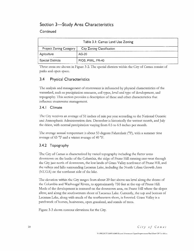
Table 3.1: Camas Land Use Zoning
Project Zoning Category City Zoning Classification
Single-Family Residential R-5, R-6, R-7.5, R-10, R-12, R-15, R-20, R1-6, R1-10, R1-20
Multifamily Residential R-12, R-18, MR-10, MF-24
Commercial BP,CC,DC,GC,NC,OC,RC,CH,CV,MX,RGX,
Industrial HI, LI, LI/BP, ML, A
C'o1JJprehe11sivf. Stor1v111ater Drai11a,~e P/011
\'-\l'ROJIOCI'\ IWOO\ 16060\ltcp"n'\~tom"'""'"' C.•p<t.ol lnip«""<'"'<·nt l'l.m\Dr.1ft Cl!' \'n ~-d"c'
19
20
Section 3-Study Area Characteristics
Continued
Table 3.1: Camas Land Use Zoning
Project Zoning Category City Zoning Classification
Agriculture AG-20
Special Districts P/OS, P/WL, FR-40
'l'hese areas arc shown in F'igure 3-2. 'fhe special districts \vi thin the City of c:ainas consist of
parks and open space.
3.4 Physical Characteristics
'l'hc analysis and n1anage1nent of stonn\vater is influenced by physical characteristics of the
\Vatcrshed, such as precipitation amounts, soil types, level and type of develop1nent, and
topography. ·rhis section provides a description of these and other characteristics that
influence stortn\vater 1nanagen1cnt.
3.4.1 Climate
'l'he City receives an average of 51 inches of rain per year according to the National ()ccanic
and i\tn1ospheric J\d1ninistration data. 1)ece1nber is historically the \VCttest 1nonth, and July
the driest, \\rith nor1nal precipitation varying fro1n 0.5 to 6.5 inches per 1nonth.
'fhe average annual tcn1pcrature is about 53 degrees Fahrenheit (0 1<'), \vi th a su1nmcr ti1ne
average of 65 °1< and a \\!inter average of 40 °P.
3.4.2 Topography
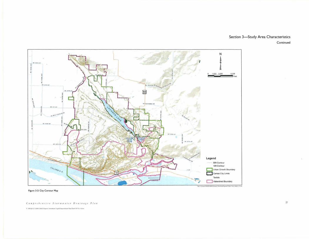
The City of Camas is characterized by varied topography including the flatter areas
do'\vnto\vn on the banks of the Colu1nbia, the ridge ofl)runc I--Iill running cast-\vcst through
the c=ity just north of do\vntO\Vn, the lo\V lands of c;rass \Talley north\vest of Prune I--Iill, and
the valleys and hills surrounding Lacamas Lake, including the North Urban Growth J\rea
(NUGJ\) on the northeast side of the lake.
'l'he elevation \vithin the C:ity ranges fro1n about 20 feet above sea level along the shores of
the Columbia and Washougal Rivers, to approximately 750 feet at the top of Prune Hill.
Much of the develop1nent is centered on the do'\vnto\vn area, on I)rune I--Iill where the slopes
allO\V, and along the SOUth'\VCStcrn shore of J_,acatnaS l__,akc. C:urrently, the top and bott0111 of
I.,acan1as l.akc, along '\vith n1uch of the northeastern shore, is forested. Grass Valley is a
patch\vork of ho1nes, businesses, open grassland, and stands of trees.
l~~igurc 3-3 shov..rs contour elevations for the C:ity.
C'it_y o.f c:a1JJf/S
\··\PROJECf\16000\!601,0\ltcp<»b \~wnnw.m·r C.1pn.il Jmp«"-""'""' l'l.rn\l)r.•ft Cl I' \'rr ~-d""
Section 3-Study Area Characteristics
Continued
3.4.3 Soils
'Ihc t)1)C of soil - granular, sandy, clayey, etc. has a strong influence on stortn\vatcr
1nanagcment, mostly in the detennination of whether storm\vater can be infiltrated or
\vhethcr it needs to be detained and conveyed to a surface \Vatcr body.
The majority of the soils within the City are classified by the Natural Resource Conservation
Service (NRCS) as Hesson, Powell, Olympic Lauren, and Dollar. These soils are mostly
poorly drained and consist of medium to moderately fine textured terrace soil. Figure 3-4
shows a map of the soil types in the city, as mapped by the NRCS.
Except for isolated pockets and areas of Hillsboro soils in the west part of the city, soil
conditions are generally not favorable for infiltration of stor1nwater. For this reason most
developn1cnts built since flow control has been required use detention sys terns and do not
infiltrate stormv.rater. 1-Io\vever, as 1nost soils have son1e infiltration capacity, the City's
stormwater ordinance (CMC 14.02) requires testing for infiltration and the use of infiltration
\vhere possible. E,vcn if detention is necessary, infiltration through the detention pond \vill
affect the size of the facility.
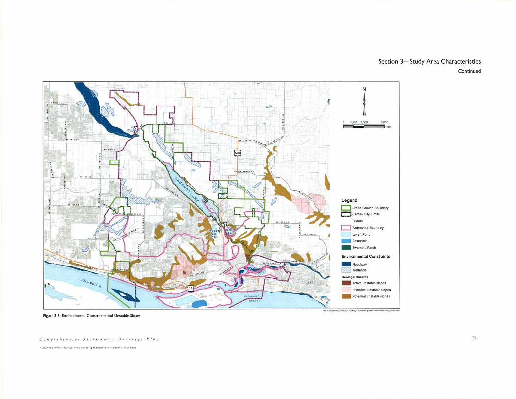
3.4.4 Geologic Hazard Areas
There are approximately 891 acres within the City that are classified as steep and unstable
slopes. The southern slope of Prune Hill is either historically or potentially unstable. Slopes
along the drainage ways coming down Prune Hill, to the north and east, arc also potentially
unstable. 'fhc hill slopes in the natural area draining to Lacamas Creek are also active and
potentially unstable. Figure 3-5 maps known and potentially unstable slopes as noted in the
City's Geographic Information System (GIS).
3.4.5 Flood Hazard Areas
I~'lood hazard areas arc areas adjacent to lakes, rivers, and streams that arc prone to flooding
during peak runoff periods. Construction of buildings and other development in these areas
is regulated in accordance with the City's floodplain ordinance. Figure 3-5 shows mapped
floodplains in the Camas area.
3.4.6 Wetlands
Wetlands arc defined by the EP1\ as areas that arc inundated by surface or ground water at a
frequency and duration sufficient to support vegetation adapted for saturated conditions.
Wetlands support valuable and complex ecosystems and development is severely restricted,
if not prohibited, in most wetlands.
C'o1J1preheHsive Sror111waler [)r11i11a~ge P/011 21
22
Section 3-Study Area Characteristics
Continued
Section 404 of the Clean Water Act regulates discharge of materials to wetlands and a permit
fron1 the 1\rn1y C:orps of I~nginecrs is required for 1nost activities that potentially itnpact
wetlands. Wetlands within the City of Camas are generally adjacent to the Columbia River
and Lacamas Lake and in the low flat lands of Grass Valley on the west side. Figure 3-5
shows wetlands as listed in the City's GJS.
3.4.7 Surface waters
lvlajor water features within the City include the Columbia River, the Washougal River,
Lacamas Lake, J ,acamas Creek, Fallen Leaf Lake, and Round Lake.
'rhe c:olutnbia llivcr begins in c:anada, enters the United States in northeastern \\!ashington,
and travels southwest through Washington to the Pacific Ocean. The river exits the
c:olutnbia H.iver Gorge shortly before it travels past dO\V11tO'\Vl1 Cainas.
'fhc \\!ashougal H..ivcr flo\vs south\vcst fron1 the Cascade l\1fountains to the City of Can1as,
\Vhcrc it C111ptics into the C:0Jun1bia 1\.ivcr.
Upper J_,acan1as c:reek (above I.,acatnas ]_,akc) receives flo\,V frotn 5 tributaries, only one of
which is within the city limits (Dwyer Creek). The other tributaries - China Ditch, Matney
Creek) Shanghai c:reek, and F'ifth Plain C:reek - enter Laca1nas C:rcck in rural Clark C:ounty.
l ... aca1nas Lake is a 2.4 1nile long lake that receives runoff fro1n the surrounding hills and flo\v
from Lacamas Creek. It is connected to Round Lake by a channel that runs under State
Route 500. The water level in Round Lake is controlled by a darn at the south end of the
lake, \vhich is run by c;eorgia Pacific Consu1ner Products l.,LC:. J__,aca1nas J__,akc has significant
algal gro\vth in the su1n1ner ti1ne, \vhich can i1npair the \Vater quality.
J__,o\ver J,aca1nas c:reck, belo\v H .. ound 1..,ake, travels do\vn a steep slope and over \Vaterfalls to
its confluence with the \\lashougal IUvcr.
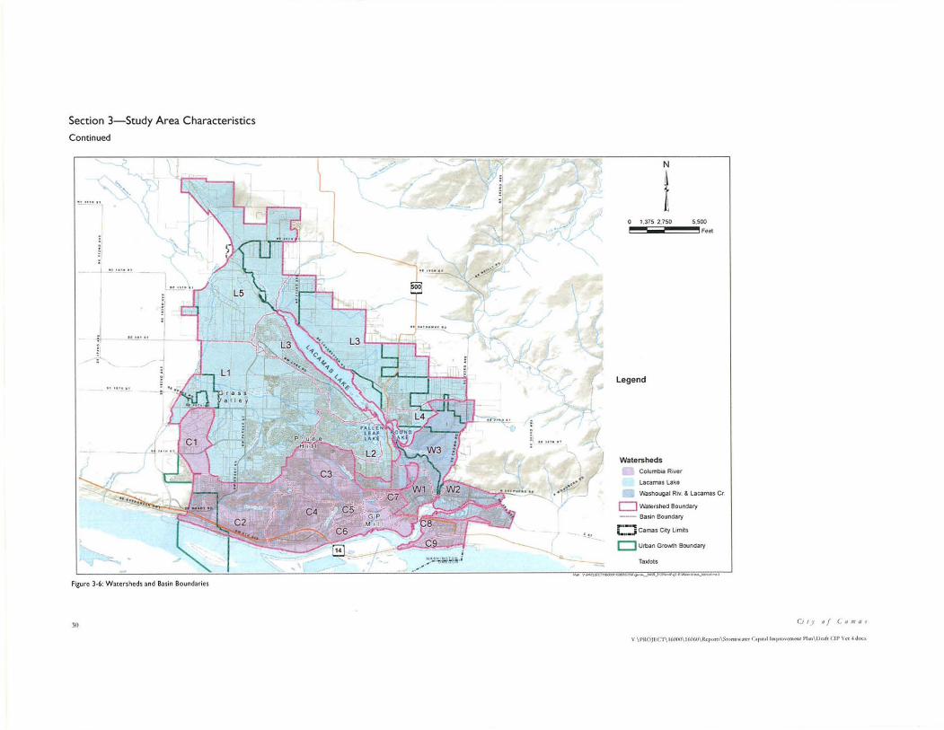
Nun1erous strea111s and creeks discharge fro1n Prune I .. Iill, including 13lue c:reek and l~orcst
Home Creek on the south side, and D\\~>er Creek on the north side. The Fisher Swale
follows the west limits of the city as it heads south to the Columbia River. See Figure 3-6 for
the location of these creeks.
3.5 Existing Storm Drainage System
]'he C:ity o\:vns and 1naintains a stortn\vater conveyance syste1n that drains approximately
7,500 acres. rfhis storm system includes approxi1nately 75 1niles of StOrlTI\Vater conveyance
pipe and 1,800 stortn\vatcr inlets and catch basins. It also includes nu1nerous culverts and
drainage channels. All stor1n pipelines are separate fro1n the C:ity's sanitary se\vcr systc1n.
('it)' o.f C'a111as
Section 3-Study Area Characteristics
Continued
'I'he C:iry has a long standing policy of requiring co1nn1crcial and residential stormwater
facilities to be privately owned and maintained. As part of its March 2010 stormwatcr code update the City retained this policy and codified it under CMC 14.02.200 Ownership and
Niaintenance.
'I'he c:ity csti1natcs that there arc 110 private storm\vater facilities \-vithin its boundaries.
l)rivate facility 1naintenance inspection occurs primarily on a co1nplaint-drivcn basis.
I-Io\vcvcr, the city's current NPDI~S permit requires that all private stortn\vater facilities built
after February 2010 be inspected yearly by the City. The City is now responsible for annual
inspections of private stonn\vatcr facilities and for ensuring that property owners tnaintain
their facilities.
J\t the time of this report the City O\vns and maintains approxi1nately 25 facilities, including
underground treatn1ent vaults, detention ponds, biofiltration swales, and wet ponds, drainage
ditches, and culverts. J\ list of these facilities is included in J\ppendix I\. It is in1portant to
note that 23 of the 25 facilities on this list were constructed before February 2010 and are
therefore not subject to the NPDES inspection requirements in the city's current NPDES
per1nit.
C'o111prthensive Stor1Nn1ater Drainage Plan 23

\ :;_
~~ co<""'a,~ ll
--...._
.~ · _,J
cf/IA ' Figure 3-1: City Limits and UGA Boundaries
Comprehe11si11e Storm11•11/er Dratna gt P l an
\" .\PROJF.CT\16000\ l(oO<IO\ Rl'J)Orts\S1orm .. ·11<'1 Ct piul lin1)rovC'mr111 Pbn\Dr-.1(1 CIP \·c, .f.docx
Section 3-Study Area Characteristics
Continue
N
I 1.500 3.000 6000
Legend ~ Uninc:orpor0>ted Urb.;sn W"..IA! GrOWlh Areas
c::.J Camas City Lunits
TaxJots
D watershed Boundary
....
25

Section 3-Study Area Characteristics
Continued
~
';
•' Cot(l4'.&1_. II
Figure 3-2: Current City Zoning
2()
_.?'.· -. !
N
I I 500 3,000 •.ooo
fut
Legend r:::::J Urban Growth Boundary
t:::J Camas City L1mts
Ta.xlots
CJ V\l'atersl'led Boundary
City of Camas LandUse
.. agricutture
- commercial
LJ industrial
- multi farnty
single famity
special districts
C11y o f (.(Imai
V \ PltOJl:'.Cf\ 16000\ 1GO<ll\Rcpons\S1onn .. ·.11cr C1pu~l lmpr<wemcnt Pbn \ ODft CIP Ver 4doc~
. :.
•I "°'~\ t• •I• .1.••
•t ..... ,., ..... .... ..... .. , ..... ,
8 I
·~ "'~-..._:o•oo.,._ ~
Figure 3·3: C ity Contour Map
C11111p r tht nr11· e Stormaatc r Dra11:1.1 ie
v rll.OJl<.T 1~'1'°"°'~ >_ .. , .. ,, ...... ,..,.._ ...... Oul'lt:IP\otl""
P I t1 11
..
.. .. ... ..
t
····· ......... ·· '• ...
-- -~ r
N
I
Section 3- Study Area Characteristics
Continued
0 1,500 3,000 8,000
Legend son contour
10ftContour
F .. t
c::J Urban Grow1h Boundary
Cj Camas C ity l imits
Taxtots
D watershed Bound1ry
....... '( ...... ~·~,~·---'-
~7
Section 3- Study Area Characteristics
Continued
r ~ · ,., ....
-!.!.. . , •• at
.... Cott,...,111.t II
Figure 3-4: N RCS Soil Categories
28
N
i t
1,500 3.000 G,000
------ ,,.;:-•
l"!..!!.!.·" ··~~ ··:.' ' 8
I
'" "~~ .. ~
Feet
-,
...... ··~·:,,·· /
-..._
'~;r
Soil Descriptions -(--~ "- .... ...,_ ... ,_ .. _ = ~=:: .. ~-:.::...-::..""·--~ . . -.. ~
:
::
---· .. ·--... _ ... _ ... ,_._ -··-· .. ---:=:::::::=:::::: __ .... __ . __ ... ____ ... _. .. _ , __ 1_ ... _ --·""'·~-.. ---··--.. -· --·-·-.. --- ...... _ .. _, -· .. --, ....... ,_ -··--.... ----e .. ,,. __ ....._ __ . __ ..... -·-·-···-.. -.._._ ___ .. ___ , :::;::.~"'::..";:.';..~:. .. __ . ....___ .. _______ ,,, __ . ____ ,_, __ -.. ... ____ 1,.--. __ .... _ ... _ ... _ :::::::::::= ---··'--· ~" -· .. ----,,..,. __
'" ..._--···---... - .... -... · .. ·-·-· .., -· ... --.... _,_ - ~---, ... ,. __ , - ~-.... ----.. -· = ::-::::= : .. ~,.:;::·.;..'*"_ .. _ ;: ::::::= ::::.:;:.-:::. "oC -· .... - .--.. --· ... -~--· .. --- .... _ ... _ ... ,_ .. _ .... ..._ ... _._ .. _ .... __ , .. '"~ .. --. _ .... _ .... _ .. _ ,,_ ... _, .. __
~---· ..... _ .. _ - ·-..--o .. ,_ .. _, ::
__ ... _ ...... __ __ _...._ .... _ .. _,
Legend
c::::J Urban Gro\o\llh Boundary
C.:J Camas City L1"'1ts
Taxlots
LJ \Natetshed Boundary
Lake \ Pond
.. Resef'V()it
- Swamp I Ma" h
;;-...., "'"'-.. ~·~~-Jo(V--Qtwoc..-__ _
C11y of Ct1 111as
V \PROJ!iCl\H,OOO\ IGOGO\ RcpClm \S1o m1 .... ~1cr Ctp1ul lmprovcmcu l Pbn\Ooft CI P Vcr 4 Joe~
...
cft>.
~-~ co,"'4'111~ "
Figure 3-S: Environmental Constraims and Unstable Slopes
C o m p r < h t 11 s 1 1• e J I o r 111 N ' 11 I t r D r a 1 n a ,( e J> I ti 11
.., ,.llOJt.CT ' '°°°' 1('0''" k..po,,.'S••••n-1 <'"{'>UI IMplO\'-~I r1 ... o,.11l'.IP v~. 4 Hon
\
,j
N
I
Section 3-Study Area Characteristics Continued
1,SOO 3.000 6,000 , ...
Legend
c:J Urban Gro'N\h Boundary
c:J Camas City limits
Taxlots
D watershed Boundary
Lako I Pond
- Reservoir
- Swamp I Marsh
Environmental Constraints
- Floodway
~WeUands Geologic: Hazards
- ActJve unstable slopes
Historical unstable slopes
- Potential unstable slopes
,...,.l(~l&:xo.~-~ ........ ~----
29
Section 3-Study Area Characteristics
Continued
.;\
Figure 3-6: Watersheds and Basin Boundaries
30
-·--·"
i ~~·~;.t.~ft · i
.. ···•·· .··
" !•
N
t 1,375 2,750 5,500
Legend
Watersheds
Cotumbla River
Lacamais Lail;e
Feel
washougal Riv. & Lacamas C r
c::J ~tershed Boundary
-- Bas.in Boundary
r:.:J Camas City Limits
c:J Urban Growth Bound ary
Taxlots 03••_ ,,__ _ _
C11 y of (. 11ma1
\' \ PROJl!.C I\ 16000\ I G0<-0\ Rcpons\$1orrn .. .11m <'.•p11~l lrnpro\cmn11 Pl •n \ O u lt ( J I'\ cr4 doc~
Section 4-Study Area Watersheds
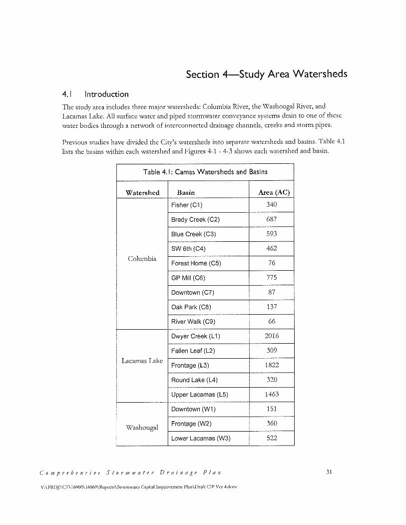
4.1 Introduction
The study area includes three major watersheds: Columbia River, the Washougal River, and
J~aca1nas I~akc. All surface water and piped stortn\vater conveyance systems drain to one of these
\Vater bodies through a net\vork of interconnected drainage channels, creeks and storm pipes.
1_)tCViOUS Studies have divided the C:ity's \Vatershcds into separate \Vatershcds and basins. '!'able 4.1
lists the basins within each watershed and Figures 4-1 - 4-3 shows each watershed and basin.
Table 4.1: Camas Watersheds and Basins
Watershed Basin Area (AC)
Fisher (C1) 340
Brady Creek (C2) 687
Blue Creek (C3) 593 I
SW 6th (C4) 462
Columbia Forest Home (C5) 76
GP Mill (C6) 775 I
I Downtown (C7) 87
I Oak Park (CB) 137
River Walk (C9) 66
Dwyer Creek (L 1) 2016
Fallen Leaf (L2) 309
Lacarnas Lake Frontage (L3) 1822
Round Lake (L4) 320
Upper Lacamas (L5) 1463
Downtown (W 1 ) 151
Washougal Frontage (W2) 360
Lower Lacamas (W3) 522
C0 0JJ1prehellsi11e StorJJl//!Ofer l)rai11a,ge Plt111 31
V:\PROJ!~Cl'\ 16000\ 16060\Rcports\Stonnwatcr Capital lmpro\'cmcnt Plan\l)rnft ClP Ver 4.docx

32
Section 4-Study Area Watersheds
Continued
'I'hc characteristics of each watershed that influence stor1nwater 1nanage1nent are presented in this
section. 'J'his includes soil types, geological hazards, steep slopes, current land use and future
dcvclopn1ent potential. 'T'his section discusses existing stor1nwatcr syste1ns \vithin each watershed,
and it also lists the number of outfall pipes larger than 24-inches, as these outfalls are regulated
under the City's NPDES Stormwater permit.
Ecology's Storrnwatcr Management Manual for Western Washington (SMMW\V') and Carnas's Stonn\vater ordinance requires \Vatcr quality treaunent and control of flows over pre-I~uropean
conditions to be provided for all devclop1nent activities that generate 5,000 square feet or 1norc of
i1npcrvious surface. 'l'he SI\JIVI\Xl\\.r e1nphasizes infiltration and lo\v itnpact over traditional flo\v
detention facilities. 'l'hc use of these 1ncasures is influenced by land use and soil characteristics,
along with how steep the slopes arc and whether there are geological hazards. 'I'his section
discusses stor1n\vater 1nanagcn1cnt options \Vith these factors in 1nind.
Stortn\vatcr 1V1anage1ncnt strategies arc designed to n1eet the city's goals and objectives, as
described in Section ()nc. 1~hc key strategy relating to storn1\vater is to support econon1ic
develop1nent \vhilc protecting the environ1nent.
4.2 Columbia River Watershed
Watershed Boundaries
The Columbia River marks the southern boundary of the City. Although all runoff in the City
eventually makes it to the Columbia River, this watershed as defined within the study area just
includes areas that either drains directly to the river through n1an1nadc conveyance pipes, or areas
that drain through stnall strea1ns to the river. 'J'he li1nits of the c:olu1nbia Iliver \Vatershcd, along
\\rith individual basin boundaries within the watershed, are sho\Vn in I'igure 4-1.
This watershed lies primarily between Prune Ilill and the Columbia River, extending to the City's
east and \Vest boundaries. rrhis \Vatershed includes a portion of do'\VntO\Vn Can1as, the Georgia
Pacific paper mill, and the neighborhoods west and northwest of downtown, including the
southern slopes of Prune Hill. One area, Basin Cl (Sec Figure 4-1 ), lies on the west edge of the
City northwest of Prune Hill. This area drains to the Columbia River through the Fisher Swale.
Soil Characteristics
NH.CS 1napped soil types in this \vatcrshed consist n1ostly of T)o\vcll, I-lesson, ()ly1npic, and Cove
soils, with some pockets ofVador and Sauvie soils (see Figure 3-4). All of these soils have
moderate to slo'\v infiltration rates, and as such infiltration of stor1nwater throughout this area is
very li1nit:cd.
Current Stormwater Systems
The portion of the watershed encompassing downtown Camas (Basin C7) is primarily drained
Cit)' o.f C'a111as
\'-\l'ltOJF,Cl"\161){10\ l(ollMl\Hcpo•(> \Strmnw.m·r C.1pot,1l lmjH"'"''"''"f\t l'l.\n\Dr.1fi C!P \"er ~.doc·x
Section 4-Study Area Watersheds
Continued
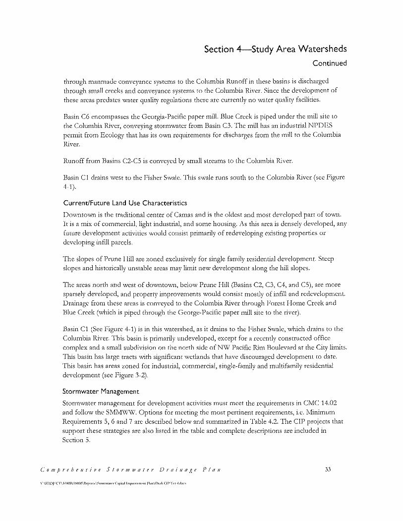
through 1nan1nadc conveyance systems to the C:olu1nbia Runoff in these basins is discharged through small creeks and conveyance syste1ns to the C:olumbia River. Since the devclop1ncnt of these areas predates water quality regulations there arc currently no \vatcr quality facilities.
Basin CG encompasses the Georgia-Pacific paper mill. Blue Creek is piped under the mill site to
the Colnmbia River, conveying stormwatcr from Basin C3. The mill has an industrial NPDES permit from Ecology that has its own requirements for discharges from the mill to the Columbia River.
Runoff from Basins C2-C5 is conveyed by small streams to the Columbia River.
Basin Cl drains west to the Fisher Swale. This swalc runs south to the Columbia River (sec Figure 4-1 ).
Current/Future Land Use Characteristics
l)o\-vntown is the traditional center of Ca1nas and is the oldest and 1nost developed part of town.
It is a n1ix of con11nercial, light industrial, and sotne housing. 1\s this area is densely developed, any fumre dcvelop1ncnt activities \VOuld consist prin1arily of redeveloping existing properties or developing infill parcels.
The slopes of Prune Hill arc zoned exclusively for single family residential development. Steep slopes and historically unstable areas may limit new development along the hill slopes.
The areas north and west of downtown, below Prune Hill (Basins C2, C3, C4, and CS), are more sparsely developed, and property improve1ncnts \vould consist mostly of infill and redevelop1nent. Drainage from these areas is conveyed to the Columbia River through Forest Home Creek and Blue Creek (which is piped through the George-Pacific paper mill site to the river).
13asin (:1 (See F'igure 4-1) is in this \Vatershcd, as it drains to the Fisher S\valc, \vhich drains to the C:olun1bia H..iver. 'l'his basin is pritnarily undeveloped, except for a recently constructed office complex and a small subdivision on the north side of NW Pacific Rim Boulevard at the City limits. This basin has large tracts with significant wetlands that have discouraged development to date. 'I'his basin has areas zoned for industrial, con1mcrcial, single-family and 111ultifa1nily residential development (see Figure 3-2).
Stormwater Management
Storm\vatcr manage1nent for development activities must 1ncet the requirements in C:MC 14.02 and follow the SMl'd\Xl\'\I. Options for meeting the most pertinent requirements, i.e. Minimum Reguirements 5, 6 and 7 are described below and summarized in Table 4.2. The CIP projects that support these strategics are also listed in the table and complete descriptions are included in Section 5.
Co1J1prehe11sive Stor1JJJVater J)rai11a~~e Pla11 33
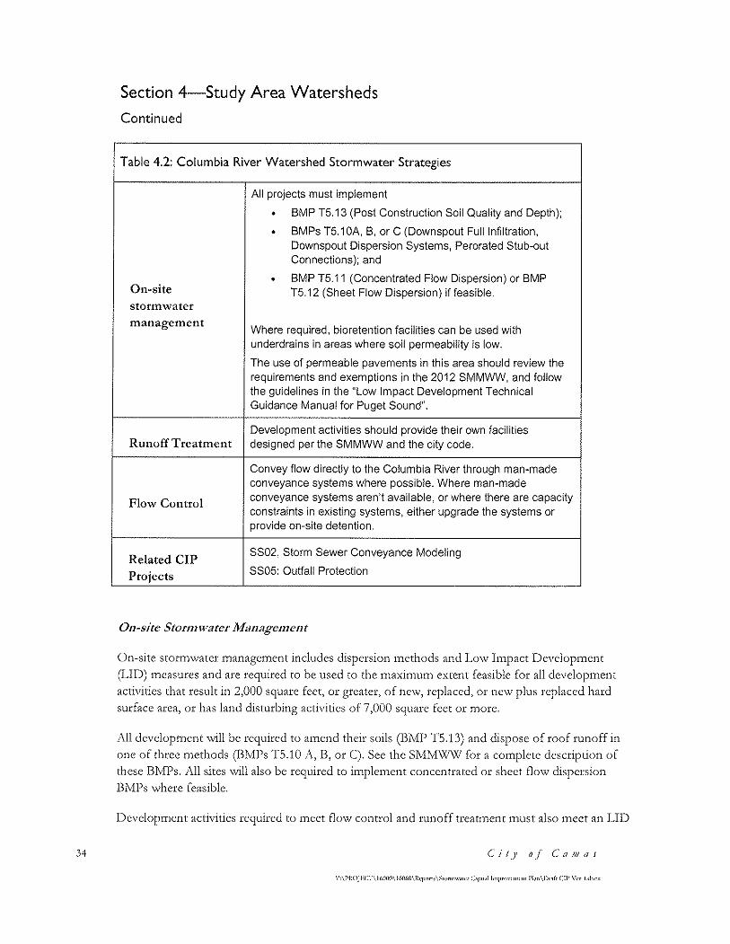
34
Section 4-Study Area Watersheds
Continued
Table 4.2: Columbia River Watershed Stormwater Strategies
All projects must implement
• BMP T5.13 (Post Construction Soil Quality and Depth};
• BMPs T5.1 OA, B, or C (Downspout Full Infiltration, Downspout Dispersion Systems, Perorated Stub-out Connections): and
• BMP T5.11 (Concentrated Flow Dispersion) or BMP On-site T5.12 (Sheet Flow Dispersion) if feasible. storm\vater management
Where required, bioretention facilities can be used with underdrains in areas where soil permeability is low.
The use of permeable pavements in this area should review the requirements and exemptions in the 2012 SMMWW, and follow the guidelines in the "Low Impact Development Technical Guidance Manual for Puget Sound".
Development activities should provide their own facilities Runoff Treatment designed per the SMMWW and the city code.
Convey flow directly to the Columbia River through man-made conveyance systems where possible. Where man-made
Flow Control conveyance systems aren't available, or where there are capacity constraints in existing systems, either upgrade the systems or provide on-site detention.
Related CIP SS02, Storm Sewer Conveyance Modeling
Projects SS05: Outfall Protection
011-site Stor1111vater Ma11age111e11t
On-site stortnwatcr 1nanagen1cnt includes dispersion 111cthods and l,o\v I1npact Dcvelopn1cnt (LID) measures and are required to be used to the maximum extent feasible for all development activities that result in 2,000 square feet, or greater, of ne\v, replaced, or new plus replaced hard surface area, or has land disturbing activities of 7,000 square feet or 1nore.
All development will be required to amend their soils (BMP TS.13) and dispose of roof runoff in one of three methods (BMPs TS.10 A, B, or C). Sec the SMM\X!\'V for a complete description of these BMPs. All sites will also be required to implement concentrated or sheet flow dispersion BMPs where feasible.
l)cvelop1ncnt activities required to 1ncet flow control and runoff trcatn1cnt tnust also tncct an I~ID
Ci!J1 o.f C'a1JJas
\'·\l'llOJIOCT\ 1(,(){l(l\ 160t.0\ltq1orti\~t<)rcnw.tt<'r C.1ptul lmpr<wct11rnt l'l,rn\Dt,ft Cll' \'a ·l.dc>r.,
Section 4-Study Area Watersheds
Continued
performance standard described on page 2-29, Volume I of the SMMW\V
Soils in the Colun1bia Iliver \V'atershed have moderate to low infiltration potential. ;\s such, so1nc
sites may be able to use IJI) measures to treat and infiltrate some portion of the site stor1n\vatcr.
\'\:'here rates are lo\V or questionable, under-drains can be placed above the bottom of the rock
cha1nbcr \Vithin bioretention facilities to convey water after being treated through the soil inedia.
Placing the under-drain above the facility bottom will allow for some infiltration. The SMM\X/\V'
provides criteria for the use of these systetns.
Development activities that arc exempt from Minimum Requirement #7 (Flow Control) do not
have to meet the SMM\V'W's J JD Performance Standard, nor arc they required to implement
bioretention, rain gardens, pcr1ncablc pavement, and full dispersion. For the C:olu1nbia H.ivcr
Watershed, this means that if the development can discharge directly to the Columbia River
through a n1an-1nadc conveyance facility \vi th available capacity, these facilities arc not needed
unless used for runoff treat1nent.
RwwffTrcatme11t
Runoff trcatt11cnt is required for any new develop1ncnt or rcdevclop1nent meeting the size
thresholds listed in the C:ity's stortn\vater ordinance. l~xisting dense devclopn1ent in do\vnto'\vn
limits the ability to place water quality facilities; streetscapc LID facilities (i.e. storrnwater planters,
pervious pavement, green roofs) and mechanical treatment systc1ns \vill likcly be the 1nost feasible
options. 1\lthough soil conditions arc not conducive for infiltration, biorctcntion facilities can still
be used with under drains. They will provide robust stormwatcr treatment and some flow
attenuation.
Ne\v residential areas on Prune I-Iill can likely acco1n111odate larger \Vater quality and flo'\V control
facilities in addition to IJD and onsite storn1water 1nanage1nent options. Particular attention
should be paid to sedi1ncnt transport and downstrean1 itnpacts since the creeks draining the hill
arc very steep and have potential to carry high sediment loads (sec C:IP projects BC 01 and BC 02
in Section 5).
Flow Contl'OI
The Columbia River is listed in the 2012 SMM\X!\V' as a flow control exempt water body, which
1neans storn1\vater discharges to the river are exen1pt fro1n the city's flo\V control require1nent,
provided runoff is conveyed directly to the river in a 1nan-1nade conveyance systetn sized to
convey the flo\V. l)evelop1nent activities that discharge stor1nwater to conveyance systems without
sufficient capacity, or to other \Vater bodies or creeks, must meet the City's flow control
requirc1ncnts.
'I'he City's do\Vt1tO\Vl1 core currently contains a storm sewer systcn1 that conveys runoff directly to
the Columbia River. The system has been in place for many years, and the maintenance staff have
C'o111prehe11sive Stor111111afer J)rai11age Pla11 35
\··\PROJECT\ l(,(K){l\ l(,1)(,l)\llq>oc1.<\~10nnw.1t(·r C1pcul lmpf<A"<·mrn1 l'l.rn\Dr,\IC Cll' \'er ~-d<K'
36
Section 4-Study Area Watersheds
Continued
not identified any areas of flooding or other signs of capacity issues. 'l'he capacity of the systcn1
will be quantified with Capital Project SS02, Stom; Sewer Modeling (Sec Section 5). If capacity
constraints arc identified, the 1nodel can be used to detern1ine pipe size upgrades.
I3asins C1-C:S discharge to s1nall strea1ns that convey storn1\vater to the Colu1nbia H.ivcr. l)evelop1nent or rcdevclop1nent in these basins \vould need to provide detention. 13asin C6 is the
mill site, which is completely developed. Runoff from Basins CS and C9 could discharge directly to the C:olun1bia lliver if the conveyance systc1n has capacity or if the systen1 size \vas increased.
4.3 Lacamas Lake Watershed
Watershed Boundaries
]'his \Vatershcd enco1npasscs the northern, mostly undeveloped, areas of the City as \vell as the
north side of Prune I--Iill and lakeshore areas. L,aca1nas L,ake is fed by I,aca1nas C:rcek, \Vhich in turn
is fed by five different creeks, n1any conveying \\later fro1n outside the c:ity lin1its. l)wyer c:reek,
\vhich conveys runoff fron1 a large portion of north\vest Ca1nas, discharges to L,acan1as C:reek.
Note that all discharges to Lacamas Lake, either directly or indirectly, are required to treat for
phosphorus.
T'he linlits of the L,acan1as ]_,ake \vatershed, along \vith basin boundaries within the \Vatershed, are sho\vn in I:,'igure 4-2.
Current/Future Land Use Characteristics
J ,arge portions of Grass Valley and the north shore of I_,acan1as J ,ake are currently undeveloped.
Grass \Talley is zoned prin1arily for industrial and co1n1nercial develop1nent, and the Northern
Urban Growth Arca (NUGA) is zoned for multi-family and single family developments, along \vi th son1e co1n1nercial and light industrial. 'rhe northern and eastern slopes of Prune I-Iill are
zoned prin1arily for singlc-fa1nily residential develop1nent but there arc so1ne 1nixed-usc areas \Vi.th
1nultifan1ily residential, co1nn1ercial, and open space tracts. 1'hc south lakcshore areas are zoned
primarily for single-family residential development with some industrial and park open spaces on
the cast end of the lake. Currently, the south side of the lake is developed as single-family
residential properties but the north side re1nains 1nostly undeveloped. Please see F'igurc 3-2 for
zoning.
The residential areas on Prune Hill and the south shore of Lacamas Lake arc unlikely to see new
development except infill or redevelopment. The industrially zoned areas in Grass Valley and
northern parts of the City have many wetlands which limit the developable area. The land north of
the lake is zoned for light-industrial, single family, and multifamily development.
Soil Characteristics
NRC:S mapped soil types in this watershed consist mostly of Hesson, Powell, Olympic, and Vader
C'it)' o.f C'aN1as
\"-\PHOJECT\l(,{)m)\ 1W60\Hq>nrL<\~t<Hm""'""' C1p1ul !1,,pro\'{'rnrn1 l'l.rn\D1"11 Cll' \\·r -Ldoc~
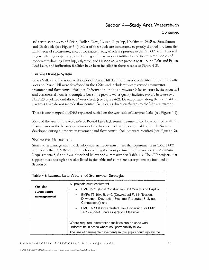
Section 4-Study Area Watersheds
Continued
soils '\vi th son1e areas of Odnc, l)ollar, Cove, I~auren, Puyallup, llockinson, ivfcBee, Sc1naih1noo
and Tisch soils (sec Figure 3-4). Most of these soils are moderately to poorly drained and limit the
infiltration of storm\vatcr, except for I,aurcn soils, \vhich are present in the NUC;J\ area. This soil
is generally 1noderate to rapidly draining and 1nay support infiltration of storn1water. l_,enses of
moderately-draining Puyallup, Olympic, and Hesson soils arc present near Round Lake and Fallen
Leaf Lake, and infiltration facilities have been installed in these areas (see Figure 4-2).
Current Drainage System
Grass Valley and the northwest slopes of Prune Hill drain to Dwyer Creek. Most of the residential
areas on Prune I-Iill \Vere developed in the 1990s and include privately-o,vncd stonn\vatcr
trcat1nent and flo\v control facilities. Infor1nation on the storn1watcr infrastructure in the industrial
and con1111crcial areas is inco111plete but sotnc private \vater quality facilities exist. There are t\vo
NPDES regulated outfalls to Dwyer Creek (sec Figure 4-2). Developments along the south side of
1,acamas 1,ake do not include flow control facilities, as direct discharges to the lake are exetnpt.
There is one mapped NPDES regulated outfall on the west side of Lacamas Lake (see Figure 4-2).
Most of the area on the west side of Round Lake lack runoff treatment and flow control facilities .
.l\. s1nall area in the far \Vestcrn corner of the basin as well as the eastern side of the basin \Vas
developed during a time when treatment and flow control facilities were required (sec Figure 4-2).
Stormwater Management
Stormwater management for development activities must meet the requirements in CMC 14.02
and follow the SMM\Xl\XI. Options for meeting the most pertinent requirements, i.e. Minimum
Requirements 5, G and 7 arc described below and summarized in Table 4.3. The CIP projects that
support these sttategies are also listed in the table and complete descriptions are included in
Section 5.
Table 4.3: Lacamas Lake Watershed Stormwater Strategies
On-site All projects must implement
• BMP T5.13 (Post Construction Soil Quality and Depth); storm water management • BMPs T5.1 OA, B, or C (Downspout Full Infiltration,
Downspout Dispersion Systems, Perorated Stub-out Connections); and
• BMP T5.11 (Concentrated Flow Dispersion) or BMP T5.12 {Sheet Flow Dispersion) if feasible.
Where required, bioretention facilities can be used with underdrains in areas where soil permeability is low.
The use of permeable pavements in this area should review the
(_'0111prthe11sive S1or1J1111a/er DraiJJa,ge Pla11 37
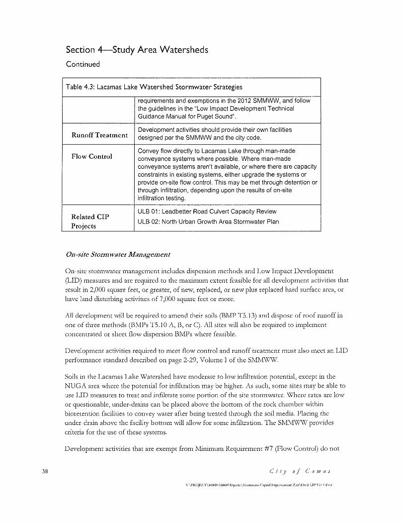
38
Section 4-Study Area Watersheds
Continued
Table 4.3: Lacamas Lake Watershed Stormwater Strategies
requirements and exemptions in the 2012 SMMWW, and follow the guidelines in the "Low Impact Development Technical Guidance Manual for Puget Sound".
Runoff Treatment Development activities should provide their own facilities designed per the SMMWW and the city code.
Flow Control Convey flow directly to Lacamas Lake through man-made conveyance systems where possible. Where man-made conveyance systems aren't available, or where there are capacity constraints in existing systems, either upgrade the systems or provide on-site flow control. This may be met through detention or through infiltration, depending upon the results of on-site infiltration testing.
Related CIP ULB 01: Leadbetter Road Culvert Capacity Review
Projects ULB 02: North Urban Growth Area Stormwater Plan
011-site Stor1111vater Ma11:1ge111e11t
()n~sitc storn1\vatcr 1nanagcn1cnt includes dispersion n1ethods and I~ow Impact l)evcloptncnt
Q,ID) measures and arc required to the maximum extent feasible for all development activities that result in 2,000 square feet, or greater, of ne\v, replaced, or new plus replaced hard surface area, or have land disturbing activities of 7 ,000 square feet or tnorc.
1\ll development will be required to amend their soils (BMP TS.13) and dispose of roof runoff in
one of three methods (BMPs TS. l 0 A, B, or C). J\l! sites will also be rc<1uircd to implement concentrated or sheet flo\v dispersion 13M1)s where feasible.
l)evclopn1cnt activities required to n1cct flo\v control and runoff trcatn1cnt 1nust also n1ect an lJI) performance standard described on page 2-29, Volume l of the SMil·f\'x/W.
Soils in the J_,aca1nas 1__,ake Watershed have 1noderate to lov..r infiltration potential, except in the
NUGi\ area where the potential for infiltration may be higher. i\s such, some sites may be able to use I.JD n1casurcs to treat and infiltrate son1e portion of the site stortn\vater. \\lhcrc rates are lo\V
or questionable, under-drains can be placed above the botto1n of the rock cha1nbcr \vi thin
bioretention facilities to convey \Vater after being treated through the soil 1nedia. !)lacing the
under-drain above the facility bottom will allow for some infiltration. The SMM\Xl\Xi provides
criteria for the use of these systems.
Development activities that are exempt from l'vlinimum Requirement #7 (Flow Control) do not
Cit)' o.f c·a111as
Section 4-Study Area Watersheds
Continued
have to meet the SMlvfW\V's LID Performance Standard, nor are they required to implement
biorctention, rain gardens, per1neablc pavement, and full dispersion. F'or the l,acatnas I__,akc
Watershed, this means that if the development can discharge directly to Lacamas Lake through a
1nan-1nade conveyance facility \vith available capacity, these facilities arc not needed unless used
for runoff treatment.
J\ capital project has been are defined and is included in Section 5 to determine what is needed for
the NUGi\ area to meet the flow control exemption. This project (ULB 01) has two components:
•
()ne is to prepare a stortn'\vater basin plan
The second is to assess the capacity of the culverts under Leadbetter Road, as these could
be used to convey water fron1 the NUC;1\ to l,acamas Lake to 1ncct the flo\v control
exen1ption. If the culverts are found to be too s1nall to convey the developed site runoff,
appropriate pipe sizes can be deterinined.
Runoff Treatment
Runoff treattncnt is required for any ne\v developtnent or redevelopn1ent 1necting the size
thresholds listed in the C:ity's stortn\vater ordinance. LID n1easurcs or more traditional treatn1cnt
measures as described in the SMMWW can be used. Note that discharges above the dam at Round
Lake are required to treat for phosphorus.
Flow Co11trol
Lacamas Lake is listed in the 2012 SMMWW as a flow control exempt water body, which means
stortn'\vater discharges to the lake arc exc1npt fro1n the city's flo'\v control regulation provided
runoff is conveyed directly to the lake in a 1nan-1nadc conveyance system sized to convey the £10'\v,
Devclop1nent activities that discharge stor111\vatcr to conveyance syste1ns \Vithout sufficient
capacity, or to other '\Vatcr bodies or creeks, n1ust meet the C:ity's flo'\v control requirements.
The north side of Prune Hill and Grass Valley will need to meet the flow control standard.
Regionally based facilities may be a feasible option for Grass Valley if private partners are willing
to pool efforts.
'T'he NUCY1\ n1ay have soils suited for infiltration. J\s such, flow control requirements inay be met through installation of U!Cs or shallow LID facilities. If UIC:s are used, these should be registered
with Ecology and rule-authorized before acceptance by the city. This report includes a capital
project to generate a stormwater basin plan for the NUGi\ area.
C" o 111 p r e h e 11 s i v e S I o r 111 w a I e r ]) r a i 11 a ,g e P I r1 11 39
40
Section 4-Study Area Watersheds
Continued
4.4 Washougal River & Lower Lacamas Creek Watershed
Watershed Boundaries
The \Xlashougal River watershed drains the southwestern portion of the City (see Figure 4-3).
Within the City limits this watershed encompasses both sides of the Washougal River, portions of
do'\Vl1tO'>Vl1 c:arnas, and tributaries to l.ower l.acamas Creek. 'I'he \Vatcrshcd boundaries are
approxi1nately SH.-14 on the south, 3rd 1\venue and (~arficld Street to the west in do\vnto\vn
Camas, and approximately SE Nourse Road to the north (the watershed extends east beyond the
City limits).
Current/Future Land Use Characteristics
'fhc do\vnto\vn area in Basin W1 is zoned prin1arily for single-fan1ily residential dcvcloprnent \\rith
so1ne co1n1nercial and 1nultifa1nily residential areas. 'rhe do\vnto\vn \Vas 1nostly developed bct\veen the 1920s and 1950s. Some infill and redevelopment may occur, but the existing development is
fairly dense. T'hc riverfront areas along the \Xlashougal l:Zivcr in 13asin \X/2 arc zoned for industrial~
co1n1nercial, and n1ulti-fa1nily and single-fa1nily residential. 1)evelopn1cnt in this basin is fron1 the
1940s to 1970s with some infill in the last 15 years. Additional infill is likely, especially in the areas
zoned for multifamily residential properties. Most of the large tracts that border the \\lashougal
River will not be developed because they belong to Camas (Parks) or are encumbered by other
facilities.
'I'hc l .. o\vcr I~aca1nas C:rcck 11asin \V'3 is located \vithin the urban gro\vth area and is zoned for
single-family residential development and park open space. This area is currently undeveloped and
\vill likely sec nc\v dcvclop1nent. See I~'igurc 3-2 for zoning. Much of this is park property O\Vncd
by Camas & Clark County. It won't be developed.
Soil Characteristics
NRCS mapped soil types in this watershed consist of Olympic and Vader soils with large areas of
fill near downtown Camas and pockets of Hesson, Powell, Rockland, Hillsboro, Washougal and
Sauvie soils throughout the watershed (see Figure 3-4). The soils arc rated as moderate to poorly
draining and \vill not likely support the infiltration of storn1\vatcr.
Current Drainage System
Stor1n\vater fro1n the downto\vn area (13asin W1) is piped \vithout treatn1ent or flow control to
discharge to the Washougal River on the south side of the basin through an NPDES regulated
outfall (see Figure 4-3).
Stor1n\vatcr fron1 so1nc of the newer residential dcvclop1nents in Basin \\12 is routed though
runoff trcatn1cnt and flo\V control facilities prior to discharging to J,o\ver I~aca1nas c:rcck just
upstream of its confluence with the Washougal River. This basin includes one NPDES regulated
outfall, as sho\vn in I''igurc 4-3.
C'it)' o.f c·a/JJ(lS
\·;\l'ltOJECf\ !60(){1\](,(l(,(l\l\eporl> \:;1ornlw.ntr C.1p11.<l lmp1<>,·M\(•cit l'l.\n\D,-_,f, Cll' \'er ·l.dorx
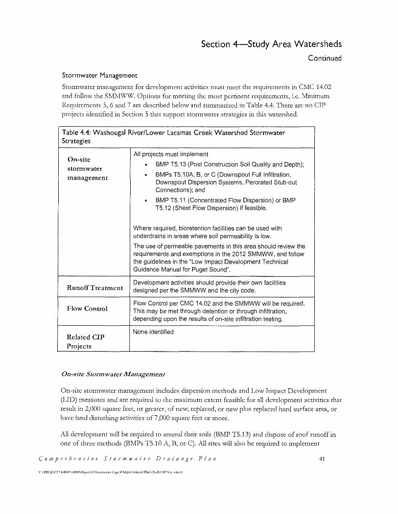
Section 4-Study Area Watersheds
Continued
Stormwater Management
Stortn\vater 1nanagc1nent for develop1ncnt activities n1ust 1ncct the requirements in CivfC 14.02 and follow the SMM\V\'V. Options for meeting the most pertinent requirements, i.e. Minimum Requirements 5, 6 and 7 arc described below and summarized in Table 4.4. There arc no CIP projects identified in Section 5 that support stortn\vatcr strategics in this watershed.
Table 4.4: Washougal River/Lower Lacamas Creek Watershed Stormwater Strategies
On-site All projects must implement
• BMP T5. 13 (Post Construction Soil Quality and Depth); storm water
• BMPs T5. 1 OA, B, or C (Downspout Full Infiltration, management Downspout Dispersion Systems, Perorated Stub-out Connections); and
• BMP T5. 11 (Concentrated Flow Dispersion) or BMP T5. 12 (Sheet Flow Dispersion) if feasible.
Where required, bioretention facilities can be used with underdrains in areas where soil permeability is low.
The use of permeable pavements in this area should review the requirements and exemptions in the 2012 SMMWW, and follow the guidelines in the "Low Impact Development Technical Guidance Manual for Puget Sound''.
Runoff Treatment Development activities should provide their own facilities designed per the SMMWW and the city code.
Flow Control Flow Control per CMC 14.02 and the SMMWW will be required. This may be met through detention or through infiltration, depending upon the results of on-site infiltration testing.
None identified Related CIP
Projects
011-sitc Stor111Jirater Afa11age1ne11t
()n~sitc stortn\vatcr 1nanagcmcnt includes dispersion 1nethods and Lo\.V Itnpact Development
(LID) measures and arc required to the maximum extent feasible for all development activities that result in 2,000 square feet, or greater, of new, replaced, or ne\v plus replaced hard surface area, or have land disturbing activities of 7,000 square feet or more.
All development will be required to amend their soils (BMP TS. 13) and dispose of roof runoff in one of three methods (BMPs TS.10 A, B, or C). All sites will also be required to implement
C'o111prebe11si11e Sror1J1wafer ])rai11a,ge Pla11 41
42
Section 4-Study Area Watersheds
Continued
concentrated or sheet tlo\v dispersion I31YfPs '\vhcrc feasible.
l)evelop1ncnt activities required to n1cct flo\v control and runoff treat1ncnt 1nust also n1eet an Lll)
performance standard described on page 2-29, Volume I of the SMlVI\VW.
Soils in this watershed are 1noderate to poorly draining. J\s such, some sites 1nay be able to use lJl) 1neasurcs to treat and infiltrate so1ne portion of the site storn1\vater. \Xfhcre rates arc lo\v or
questionable, under-drains can be placed above the botton1 of the rock chamber \vithin
bioretention facilities to convey water after being treated through the soil media. Placing the under-drain above the facility bottom will allow for some infiltration. The SMMWW provides criteria for the use of these systen1s.
Ru11off Treatme11 t
Sin1ilar to the dO\Vl1tO\V11 area in the c:olu1nbia lliver \Vatcrshcd, existing dense developn1cnt lirnits
the \Vatcr quality trcatn1ent options in Basin \\/1 to LJl) facilities and 1nechanical syste1ns.
l\esidcntial infill in I3asin \X'2 can likely accon1n1odatc larger '\Vater quality and flo\v control
facilities in addition to LID techniques.
Water quality treatment must meet the TMDL standards since Lacamas Creek is a 303(d) listed \Vater body; please sec the discussion in Section 2.2.2 for 1norc infonnation.
llunoff treattnent is required for any new develop1ncnt or redcvcloptnent n1ecting the size thresholds listed in the c:ity's storn1\Vater ordinance. IJD tneasures or 1nore traditional treattncnt
measures as described in the SMMWW can be used.
Flow Co11trol
I)ischargcs to the \Xlashougal lliver and to l,o\ver L,aca1nas Creek and its tributaries n1ust 1neet the
C:ity's flo\V control require1nents, as these '\Vater bodies arc not included on the flo\v control
cxe1nption list in the 2012 SI\1Iv1\Xf\X/. H.unoff trcattncnt is required for any ncv,1 developn1cnt or
redeveloptncnt tneeting the size thresholds listed in the c:ity's stortn\vatcr ordinance.
'I'hc banks of l,o\ver Lacan1as Creek and its tributaries arc steep \vi th active and potentially unstable slopes. Meeting the flow control requirements for new development in Basin W3 will be essential to prevent further degradation.
('it)' o.f Cr11J1as
\' \l'ltOJl'.C'l'\ll>\Hlll\!M)(,(l\Rq>on;\Srnimw.ta·rLip,1.1l lmp1r>w""'"l PL\11\Dc.1fr (:ll' \'t< ·l do,·,
• L1
• ·~
•
. ""•. '"""
··-............................. .. Figure 4· I: Columbia River W atershed and Basins
Comprthtflllt' t Stor11111· oter Vr(1111age
v ,Pl.OJtCTil '-000' 1(4'(111.rro• .. ·.SIO•l'I'"'•"'' r ..,.t.11 ... , . _ ..... n .. · o·~(•l:IP v .. •dO>C"o
p I 11,,
.-·'
_ ... -·-·-·-·--·-·-·-·-·-·-·-·-·-·-·-·'
... -·-·-· ,., ... ·' ·' ·'
,, .... ·' ""
. ;
W118MI MOTOH i .,. .... -·-·-·-OH·.-c;o;,-·
Section 4 - Watershed Stormwater Management Continued
N
! 0 S50 1,700 3.400
Feet
Columbia RiverWatershed
Legend
• Stormwater Faci ~ty
A 24" 0uttall
.A, 36"0utfall
8 48" 0 utfa ll
- S!ormLine - Culvert
lnlintStorage ·······- Overnow
·······-Dummy
c::J Watershed Boundary
-- Basin Boundary ,. ..... . ~ . .... ; Camas City Limits
c:J Urban Growth Boundary
Taxlots
~3
Section 4 - Watershed Stormwater Management Continued
'""'l, "'. ~ __, ,, , l
I f ~ 1 L!• ...., I • l ~.,
}\ ' - 1·, !'\ , ~·. , ,,.,,,, '\ 1 -"\..."'~
. \ ''r· r \.._ ")~ ... . -'l
... l ..... ,
~(
L2.___
Figure 4-2: L3camas lake Wa[ershed and Basins
~~
~I ~ ~)
N
I Lacamas Lake Watershed
Legend
• Stormwater Faci~ty
.A 24" 0utta ll
..&. 36"0uttall
&, 48"0uttall
- StormL1ne - Culver1
==- ln~neStorage ....... _ Ovetflow
·······- Dummy
c:J Watershed Boundary
-- Basin Boundary
i~:J C amas City Limrts
Q Urt>an Growth Boundary
Taxlots
·•~'l"HQ.JC.;1;ill(IO(;a.1~--f1ol.ll\ 041-'~--
. , P~Oll
C1 IJ q/ Ca 111 as
!C:T. 1'°'-'0 1~)1 k'l'Of\•\ S1"m>"' •~• <.tpoul lt:1>p1~•f'MC'fll • Phn Ou(1 <.II'\'~ • • .bo.
~·~
£: ..... ~-~ ... ~ ~ ~ ( ~ FA LLEN \\
L EAF
~ LAKE \ '
I I
~ ,...._ ~, \
~ ' \ L2 '
--.. / '· .... !~'--~---. ·' . ~ _ _,, ! ,l .. . ' It
'
~·· . .,
1 .. l~ r$ ....
r- .
I "i-·"', _ _.~:;!:fc """ ~r~:i-·
10""-.G P
M i 1 1
Figure '4-3: Washougal River & Lower lacamas Creek Watershed and Basins
Comprtht1111r• e S1or111» atcr Dr11in1J .(t p I''"
.. 'lOJl.( T l«'OO·l~l·r<>"' ·~·~-..... ,r'f"toll"'r'-·"'·M•'OuftCIP\'•••'°""
W3
Section 4 - Watershed Stormwater Management Continued
N
I 435 870 1.740
Feet
Washougal River & Lacamas Creek W atershed
·\
.. . J ·· .. ~ ;. 0- J :.:~ ;1 LACAMAS LA~E ...... ~I
~A) j ~· Yl~SHOOGALR.&
COLUMBIA~ . "< . ~)
• Stormwater F acitity
A. 24" 0utfall
& 36"0u\fall
& 46"0utfa\I
- Storml1ne - Culvert
====- JnlineStorage · ······- Overflow
······· - Dummy
c:J IJVatershed Boundary
-- Basin Boundary
... . 1 ..
ii-.,J Camas City Limits
c:J Urban Growth Boundary
Taxlots
,~ .. _l«Ult_I 'i" •• t-~-·---
45

Section 5-Capital Improvements
5.1 Introduction
'fhis section describes the capital i1nprove1nent projects for this first version of the c:ity's Storn1\vatcr c:apital In1provcn1ent Plan. 1~hc projects described in this section \VCtC selected
by City staff and arc based on:
/\ddressing existing facilities in need of repairs
Addressing identified flooding concerns
• Coordinating stormwatcr facility design and construction with transportation project
needs
•
•
lZcducing reoccurring tnaintcnance activities
Planning for future development and capacity needs
'rable 5.1 lists the rcco1n1ncnded C:IP's, a priority assign1nent (lo\v, medium, or high), and an
estitnated itnplcmentation cost. J\ City 1nap \vith CIP locations is sho\vn in F'igure 5-1.
'I'hcre arc nvo basic categories of capital improvc1ncnt projects; those that deal \vith the
planning aspects of storm\vater 1nanagen1ent, and those that involve the improvc1nents of Structures and facilities in the C:ity's StOrlTI\Vater drainage systctn. ~fhc projects arc broken OUt
by watershed, and the project descriptions include the basin name and the location, where
applicable.
The project numbering is based upon the basin the project is located in, except for projects
that are City-\vi.dc. H.eferring to 'rable 5.1, "SS" stands for Storm Sc\-ver and is used for City
wide projects. "DC" stands for Dwyer Creek and is used for projects in the Dwyer Creek
basin. "Ul~B" stands for Upper I~acan1as I3asin, and ''(=Iz" is for Colu1nbia H.iver.
Table 5.1: CIP Summary
Project Name
SS 01 Transportation Related Stormwater Facilities
SS 02 Stor1n Sewer Conveyance !\1odeling
DC 01 North Dwyer Creek Stormwatcr Basin Plan
DC02 Grass Valley Stormwater Basin Plan
('01?1prehe11si11e Stor111111a/er Drai11r1~~e P!t111 47
\' \1'HOJECf\l6!lOIJ\ IG!l(>(l\lh·prnt>\~tNmw.uN C.1p,,.•l lmpr<!\·enwm l'l.m\l)r.ofr Cll' \'er 4.doc'
48
Section 5-Capital Improvements
Continued
Table 5.1: CIP Summary
Project Name
DC03 Pacific Rim Boulevard Crossing
DC04 Julia Street Stormwater Pond Retrofit
DC05 Thomas/Carson Estates Runoff Control
ULB02 North Urban Growth Arca (NUGJ\) Stormwater Basin Plan
CR 01 Forest IIomc Road Sediment Basin --
CR02 Blue Creek Sediment Basin
Separate project sheets have been prepared for each project listed in Table 5.1. These sheets are included on the following pages and include a description of the problem to be addressed and a description of the proposed solution. The sheets also include a cost estimate and possible funding sources.
Cit] o_( (~a111as

....__... )
I ~- . /
ll y y
.•, "..>it
J'
Figure 5-1; C I P Project Locations
C ompr e h e n sive Stormu• a t t r /J r n i na~ e P l a n
\ ' \ PROJECT\ ll-OOO\ IG060\ Rcpon)\Srorm9.'lter Ctp11al lmpro,·cmcnt Pb.n\ Drtft CIP \ ' cr4.doc-i:
r
.,
N
! 0 1 500 3 000
EH
C'J C1rnas Ctty Limit$
T:ildot$
c::J wa1ersriec1 SouOOary
-- &ibba sin Boundary
Cotumbt:i
LOC.1rno1$Lake
"NuhO!.lgal
6000
·~·
Section 5- Capital Improvements Continued
~9
~ c • 0 ~ ·p ·;:; u c " 0 "' u
7.
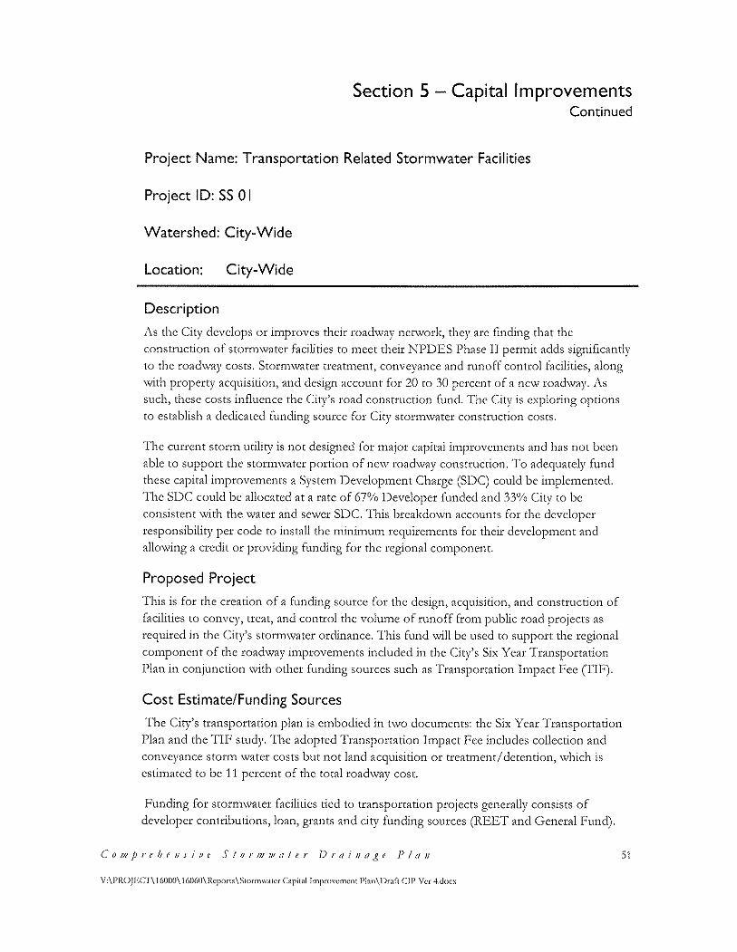
Section 5 - Capital Improvements Continued
Project Name: Transportation Related Stormwater Facilities
Project ID: SS 0 I
Watershed: City-Wide
Location: City-Wide
Description
i\s the c:ity develops or improves their roadway nct\vork, they arc finding that the
construction of stor1nwater facilities to n1ect their Nl)l)ES l)hase II perinit adds significantly
to the road\vay costs. Stor1nwater treatment, conveyance and runoff control facilities, along
v.rith property acquisition, and design account for 20 to 30 percent of a new road\vay. J\s
such, these costs influence the C:ity's road construction fund. 'l'hc C~ity is exploring options
to establish a dedicated funding source for C:iry stortn\vater construction costs.
'J'he current storm utility is not designed for 1najor capital i1nprove1ncnts and has not been
able to support the storn1\vatcr portion of nc\v road\vay construction. 'I'o adequately fund these capital improvements a System Development Charge (SDC) could be implemented.
The SDC could be allocated at a rate of 67% Developer funded and 33% City to be
consistent \Vith the \Vater and sewer SI)C. 'l'his brcakdo\vn accounts for the developer
responsibility per code to install the 1nini1nu1n requirements for their develop1ncnt and
allowing a credit or providing funding for the regional component.
Proposed Project
]'his is for the creation of a funding source for the design) acquisition, and construction of
facilities to convey, treat) and control the volutne of runoff fron1 public road projects as
required in the City's stormwater ordinance. This fund will be used to support the regional
co1nponent of the roadway itnprovements included. in the C:ity's Six Y car 'I'ransportation
Plan in conjunction with other funding sources such as Transportation Impact Fee (I'IF).
Cost Estimate/Funding Sources
'I'he c:iry's transportation plan is embodied in t\VO documents: the Six Year 'I'ransportation
Plan and the TIF study. The adopted Transportation Impact Fee includes collection and
conveyance storm \vater costs but not land acquisition or treatment/ detention, \vhich is
estimated to be 11 percent of the total roadway cost.
I_;unding for stor1n\vater facilities tied to transportation projects generally consists of
developer contributions, loan, grants and city funding sources (REET and General Fund).
Co111prehe11si11e Stor1J1JJ1ater f)rc1i11age Plr111
V:\PROJ!~Cl'\ 16000\ 16060\Rcports\Stormw;llcr Capital lmprovcmcnt P!an\l)rafl CJP Ver 4.<loo:
51
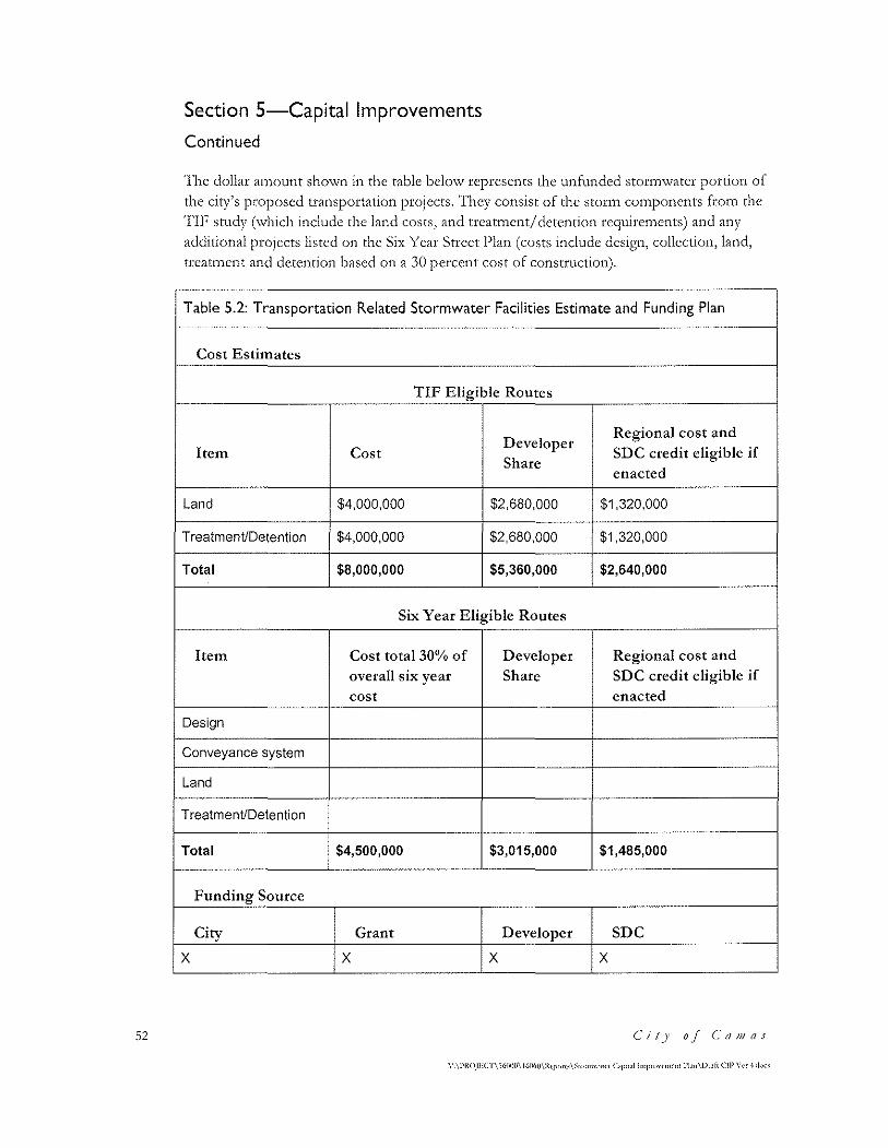
52
Section 5-Capital Improvements
Continued
'l'he dollar atnount shown in the table below represents the unfunded stor1n\vatcr portion of
the city's proposed transportation projects. 'l'hcy consist of the storn1 con1poncnts frotn the
TIF study (which include the land costs, and treatment/ detention requirements) and any additional projects listed on the Six Year Street I)lan (costs include design, collection, land, treatment and detention based on a 30 percent cost of construction).
Table 5.2: Transportation Related Stormwater Facilities Estimate and Funding Plan
Cost Estimates
TIF Eligible Routes
Developer Regional cost and
Item Cost SDC credit eligible if Share
enacted
Land $4,000,000 $2,680,000 $1,320,000
TreatmenVDetention $4,000,000 $2,680,000 $1,320,000
Total $8,000,000 $5,360,000 $2,640,000
Six Year Eligible Routes
Item Cost total 30% of Developer Regional cost and
overall six year Share SDC credit eligible if
cost enacted
Design
Conveyance system
Land
TreatmenVDetention
Total $4,500,000 $3,015,000 $1,485,000
Funding Source
City Grant Developer SDC
x x x x
C'it)' o_l C'a111as
Section 5-Capital Improvements
Continued
Project Name: Storm Sewer Conveyance Modeling
Project ID: SS 02
Watershed: City-Wide
Location: City-Wide
Description
'I'he City's conveyance systc1n is over 70 years old in some locations in the do\vnto\vn core
and the City anticipates the need to repair or replace some of these pipes. In addition, the
carrying capacity of son1e of the City)s stor1n\vatcr pipelines has been reached or exceeded.
J\s systcn1s age and replacc1nent or upgrades arc considered, it is i1nportant that new systctns
are sized properly to convey existing t1o\VS and to carry future flo\vs that tnay result frotn
new development or redevelopment. The City docs not currently have a model for helping
thc1n decide ho\v to size a replace1ncnt systc1n.
New pipes can be sized fairly easily using simple models (i.e. Manning's Equation). These
rnodels can quickly determine the pipe size needed to convey tlo,vs assuming open channel
flo\v. I-Io'\vcvcr, they can underesti1nate the capacity of existing syste1ns, as they do not
account for syste1n surcharging. In addition, the hydraulics of existing pipe systems can be very co1nplex. 'rhis is because flo\v enters the syste1n fro1n 1nany different locations, and the
interaction bct\vccn these flo\VS co1nbined \vi th the characteristics of the pipe system itself causes the water to do unpredictable things, even moving upstrean1. Frhe equations and
1nethods to 1nodel these systems arc co1nplex but are no\v routinely perfonned \vith
co1nputer 1nodels.
1\ hydrologic and hydraulic model of the city's conveyance systen1 \vould provide the1n \Vith
a tool for planning and building necessary in1prove1nents. T'his can be used for existing
systc1ns to size upgrades, and for sizing ne\v systems where planned by the city.
Proposed Project
Develop a hydraulic computer model of the City's storm sewer pipe system. This model can be built in phases and \vould only need to include the larger pipes \vhich serve as systen1
trunk se'.-vers or backbones. Itnportant systems to model include:
• Systems \vhere excessive surcharging (water coming out of 1nanholes or catch basins) occurs
C~o111prehe11sive Stor1JJJJ1a/er J)rai11age Plr111 53
\' \l'HOJIOCT\ !61KKJ\ IWloO\lteprn•' \~'°'"'""·""' C.<pl!al lmpr<"·crne1H Plm\Dr.1ft CIP \'<'< -1.dnrx
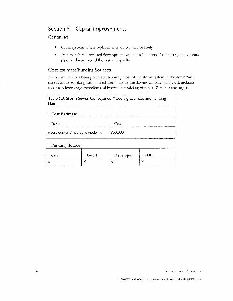
54
Section 5-Capital Improvements
Continued
Older systems where replacements arc planned or likely
Systcn1s \Vhere proposed develop1ncnt \Vill contribute runoff to existing conveyance
pipes and inay exceed the systern capacity
Cost Estimate/Funding Sources
A cost estimate has been prepared assuming 1nost of the stor1n systen1 in the downto\vn core is 1nodeled, along with li1nited areas outside the do\vnto\vn core. 'l'he \Vork includes
sub-basin hydrologic modeling and hydraulic modeling of pipes 12-inchcs and larger.
Table 5.3: Storm Sewer Conveyance Modeling Estimate and Funding Plan
Cost Estimate
Item Cost
Hydrologic and hydraulic modeling $50,000
Funding Source
City Grant Developer SDC
x x x x
(' i IJ' o.f Ca JJJ as
\'-\l'ltOJEC r\ 16000\ 16lllo0\lkp<>n<\~•om1w"'"' C1p11.1l lmprim·nwn1 Plan\Dr.11'! CIP \'<·r ·!don
Section 5-Capital Improvements Continued
Project Name: North Dwyer Creek Stormwater Basin Plan
Project ID: DC 0 I
Watershed: Lacamas Lake
Basin: Dwyer Creek
Location: North Dwyer Creek Basin
Description
The North Dwyer Creek study area is bounded by NW Lake Road on the south, Friberg H.oad on the \Vest, N\\/ Payne l\.oad 011 the cast, and the c:a1nas I'v1eadO\VS dcvelop1nent on
the north (see Figure 5-1). The City developed a comprehensive land-use master plan for this area in 2001 and will be updating this plan in 2012.
The updated basin plan will include a stormwater management strategy that addresses flow control, \Vater quality, and conveyance. T'his plan v..rill be designed to meet the City's recently adopted stor1n\vater ordinance and the Stortn'\vater fvfanagetnent Manual for Western
Washington (SMJV!W\V').
Stonn\vater from this area is tributary to North l)\V)'Ct Creek, \Vhich runs north along the
'\Vest edge of the study area, then cast to l....1aca1nas c:rcck, which flows to Laca1nas l,akc. Lacamas Lake eventually discharges to the Washougal River approximately one-half mile from its confluence with the Columbia River.
Lacamas Creek and five of its tributaries (D\\~'er Creek, Fifth Plain Creek, Shanghai Creek, Matney Creek, and China Ditch) are listed on Washington State's 303(d) list of impaired \Vatcr bodies for fecal coliforn1 bacteria, tc1npcraturc, dissolved oxygen, and pl-I. 1\ Total
Maximum Daily Load (TMDL) plan is currently being prepared by the Washington State Department of Ecology for Lacamas Creek and four of the five tributaries.
'Ihe (:ity requires phosphorus treatincnt in the l,acamas \Vatcrshcd above the dan1 at the
south end of Round Lake for all development sites exceeding one acre in size.
Proposed Project
This C:IP is to provide funding for development of a stormwater basin plan in conjunction with the updated land-use master plan. This plan should include the following:
C'o111prebe11siPe Stor111JJ1a/er ])rail/a~~e Plan 55
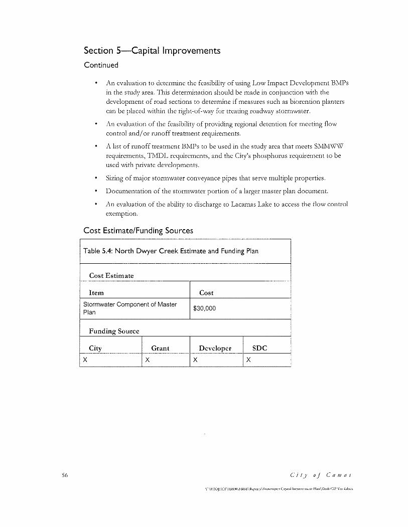
56
Section 5-Capital Improvements
Continued
1\11 evaluation to dctcrnUne the feasibility of using I.,o\v In1pact Dcvelop1nent BlV11Js in the study area. 'rhis deter1nination should be made in conjunction \vith the
dcvelopn1cnt of road sections to detertnine if ineasures such as biorcntion planters can be placed \vithin the right-of-\vay for treating road\vay stor1nwater.
1\n evaluation of the feasibility of providing regional detention for 1nccting flow
control and/ or runoff treattnent rcquirc1ncnts.
A list of runoff treatment BMPs to be used in the study area that meets SMM\V\V rcquire1nents, 'I'lVfl)l~ rcquircn1ents, and the City's phosphorus rcquircn1cnt to be
used \Vith private develop1nents.
Sizing of n1ajor stor1n\vater conveyance pipes that serve 1nultiplc properties.
l)ocutnentation of the storn1watcr portion of a larger tnaster plan docu1nent.
1\11 evaluation of the ability to discharge to L.aca1nas l__,akc to access the f1o\v control
exe1nption.
Cost Estimate/Funding Sources
Table 5.4: North Dwyer Creek Estimate and Funding Plan
Cost Estimate
Item Cost
Stormwater Component of Master $30,000
Plan
Funding Source
City Grant Developer SDC
x x x x
c:it)' o.f C"rlll/{{S
Section 5-Capital Improvements
Continued
Project Name: Grass Valley Stormwater Basin Plan
Project ID: DC 02
Watershed: Lacamas Lake
Basin: Dwyer Creek
Location: Grass Valley (vicinity of NW 38th Street and Parker Road)
Description
The Grass Valley Arca of Camas is bordered by Pacific Rim Boulevard on the south, NW
Dahlia Road on the cast, Lake Road on the north, and the City limits on the west. The center of c;rass \Talley is roughly at the intersection of Parker H .. oad and 381
h J\vcnue. 'l'he area
contains both hon1es and many light industrial and technology businesses.
'Ihe C~rass \Talley area contains many acres of lo\v-quality '.-vetlands. 13ecausc of this \Vetland
designation, these properties have rc1naincd undeveloped and are used for grassland farn1ing.
The headwaters of Dwyer Creek are on the northwest slopes of Prune Hill. The creek runs
north to NW 38th Avenue, then west along the south side of the road until it reaches Parker
Road. 1:.'rom there it crosses the road diagonally fro1n the southeast to north\vcst \vhere it
then travels along the north side of NW 38th Avenue for approximately 1,200 feet. At that
point it turns north through private properties.
\Xlhere l)\vyer C:reck turns north an intcnnittent strea1n carries runoff fro1n south to north under NW 38th i\ venue and joins with Dwyer Creek. At this location along NW 38th
J\venuc, nuisance flooding that impacts N\Xl 38th 1\venue occurs on a frequent basis.
Proposed Project
This project is to develop a plan that will:
•
•
Develop a plan for the property O\vners' that consolidates and enhances the portions
of the delineated wetlands on these properties, allowing other portions of the
properties to be developed.
l)evelop a concept for a regional stormwatcr facility to meet the city's flo\v control
requirement. This facility could be integrated with the wetland enhancement area and
could provide flow control for the private parcel's and for the city's planned improvcn1cnts to N\Xl 33th 1\venue.
c·o111prehe11sive Storv1111a/er Drr1i11r1,ge Pla11 57
\'·\l'RO_JIOCT\ 160llll\ !(,()(,(l\llcpnn, \.~locmw.llc< C.~'1t.i\ hnprownH·J\I l'l.1n\Dr.1fc Cl!' Ver ·!.doc'
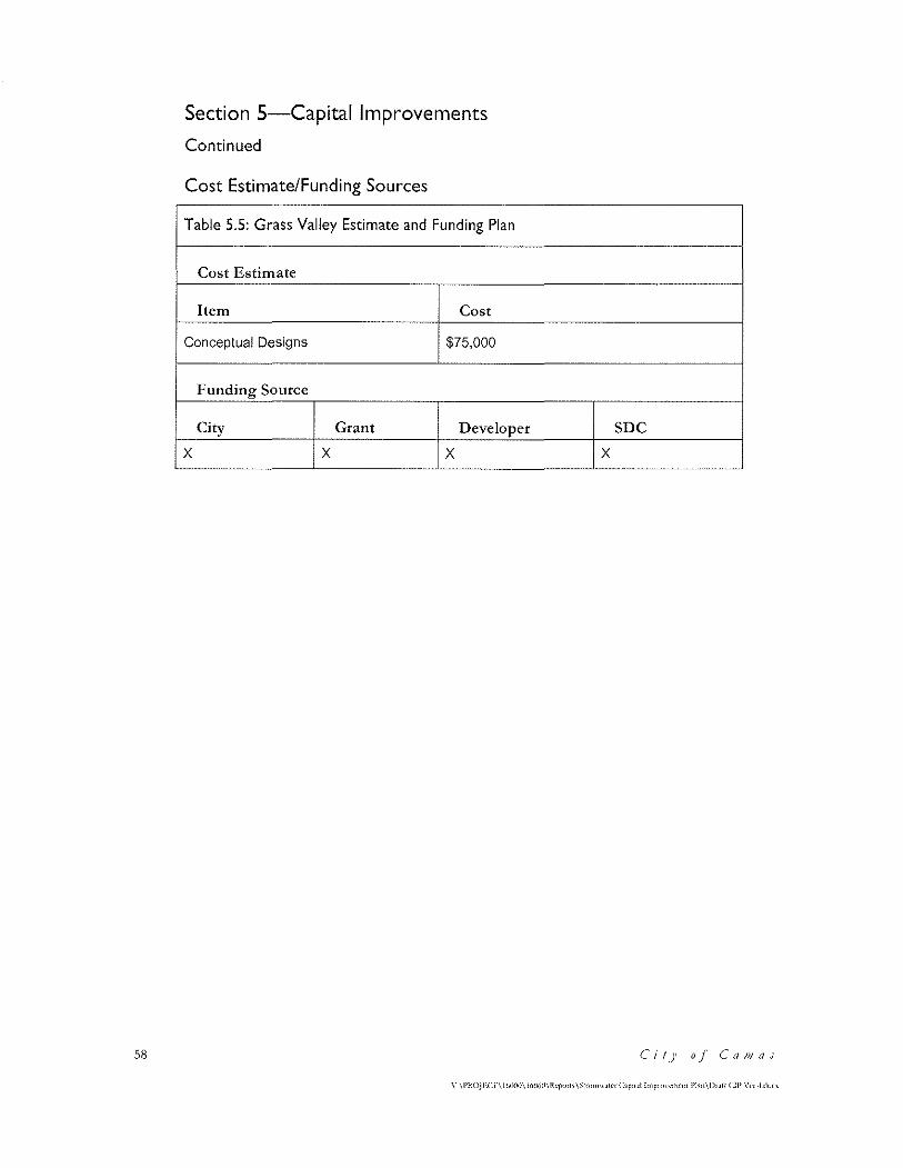
58
Section 5-Capital Improvements
Continued
Cost Estimate/Funding Sources
Table 5.5: Grass Valley Estimate and Funding Plan
Cost Estimate
Item Cost
Conceptual Designs $75,000
Funding Source
City Grant Developer
x x x SDC
x
Ci!)' o_f Ca111as
\"·\l'HOJJ;.Cf\lUOllll\ 1r,06i1\lkrrn1;\$1o•mwMt' C1pot•l lo>1p•ownwnc Pirn\Dr1i1 CJP \'c·r ·!<lor'
Section 5-Capital Improvements
Continued
Project Name: Pacific Rim Boulevard Crossing
Project ID: DC 03
Watershed: Lacamas Lake
Basin: Dwyer Creek
Location: Pacific Rim Boulevard west of NW Fisher Creek Drive
Description
l")acific 1Zi1n 13oulevard experiences routine flooding in a lO\V spot \VCSt of N\Xl Fisher c:reek Drive and the entrance to Sharp Electronics (See Figure 5-1 ). The stormwater conveyance system that collects stor1n\vater in Pacific Ritn Boulevard con1cs fro1n both directions to this lo\v point and discharges north to a tributary of l)\V)'Cr Creek. In addition, there arc t\vo culverts under the road that carry storm\vatcr fron1 properties south of the street to the
north side.
T'he land adjacent to IJacific H.itn Boulevard rises steeply to the south. 'l'he area contains
shallo\v ground\vatcr and surface \Vatcr that runs to\vards I)acific H..in1 13oulcvard. 'fhc
property O\vncr has atten1ptcd to collect this \Vater \vith F'rcnch drains and surface trenches.
This water is directed to culverts that carry it under NW Pacific Rim Boulevard.
Proposed Project
Determine the cause of the flooding at this low spot and develop a plan for alleviating this problem. This should include:
A hydrologic study that includes the private parcel south of Pacific Rim Boulevard
The development of a model of the system to determine capacity
Develop1ncnt of a conceptual design and construction cost estimate
CoJJ1jJrehe11sil'e StorJJJ//1(1/er J)rai11a,g1? PlaH 59
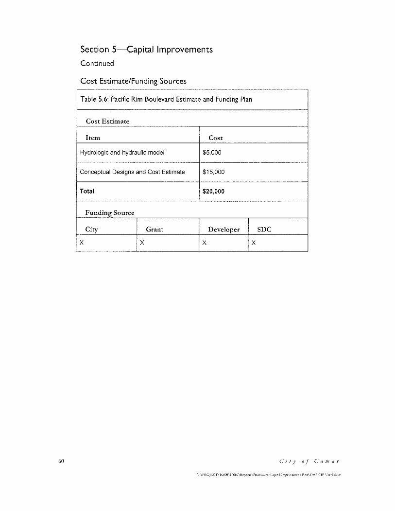
60
Section 5-Capital Improvements
Continued
Cost Estimate/Funding Sources
Table 5.6: Pacific Rim Boulevard Estimate and Funding Plan
Cost Estimate
Item Cost
Hydrologic and hydraulic model $5,000
Conceptual Designs and Cost Estimate $15,000
Total $20,000
Funding Source
City Grant Developer
x x x x SDC
Ci!)' o./ C'a111as
\'·\PltOJJ'.Cr\ l61~l0\ll>060\R"f"'"' \~w1mw.uer C'P"·'l lmpmwmcm l'bn\lk•ft C!I' \"<·r ·Id'""
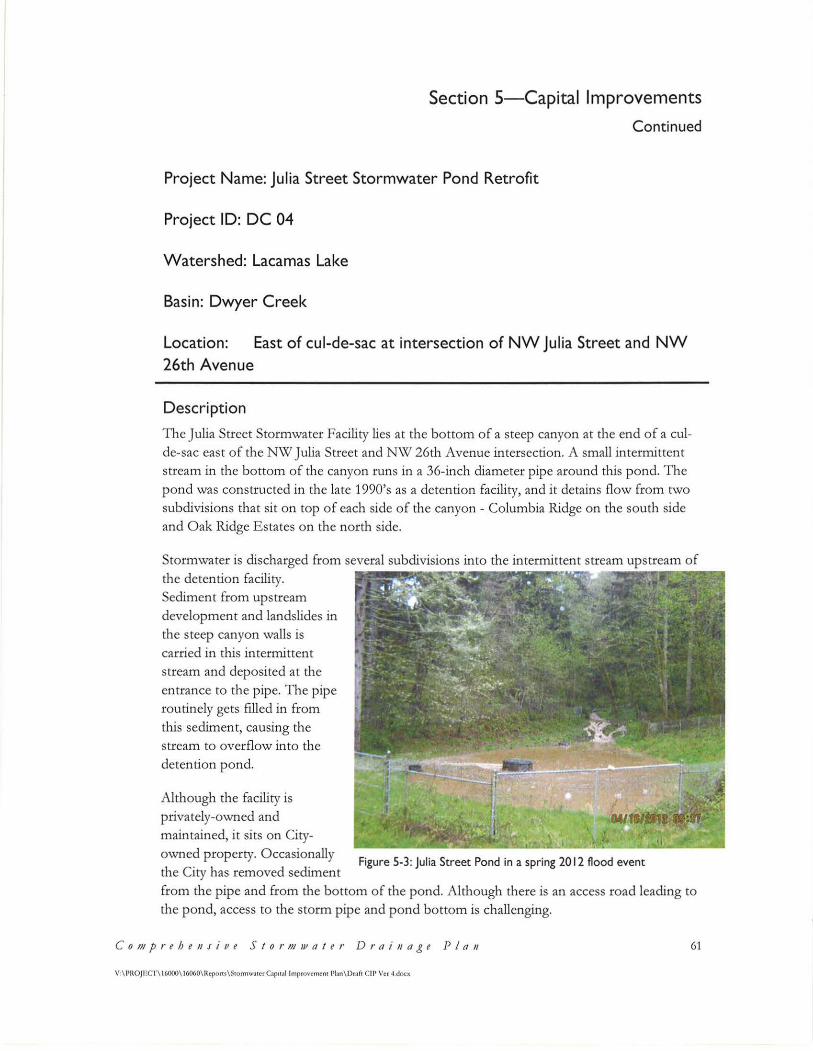
Section 5-Capital Improvements
Continued
Project Name: Julia Street Stormwater Pond Retrofit
Project ID: DC 04
Watershed: Lacamas Lake
Basin: Dwyer Creek
Location: East of cul-de-sac at intersection of NW Julia Street and NW 26th Avenue
Description
The Julia Street Stormwater Facility lies at the bottom of a steep canyon at the end of a culde-sac east of the NW Julia Street and NW 26th Avenue intersection. A small intermittent stream in the bottom of the canyon runs in a 36-inch diameter pipe around this pond. The pond was constructed in the late 1990's as a detention facility, and it detains flow from two subdivisions that sit on top of each side of the canyon - Columbia Ridge on the south side and Oak Ridge Estates on the north side.
Stormwater is discharged from several subdivisions into the intermittent stream upstream of the detention facility. Sediment from upstream development and landslides in the steep canyon walls is
carried in this intermittent stream and deposited at the
entrance to the pipe. The pipe routinely gets filled in from this sediment, causing the stream to overflow into the detention pond.
Although the facility is privately-owned and maintained, it sits on Cityowned property. Occasionally the City has removed sediment
Figure 5-3: Julia Street Pond in a spring 2012 flood event
from the pipe and from the bottom of the pond. Although there is an access road leading to the pond, access to the storm pipe and pond bottom is challenging.
C o111prehe11sive Storm1JJater Drai11age P/011 61
V·\ JlROJECf \ 16000\16060\Rcport.s\StonnwAtcrC;ap11<1l lmprovemeni Plan\DrAfl CIP Ver -1.Jocx
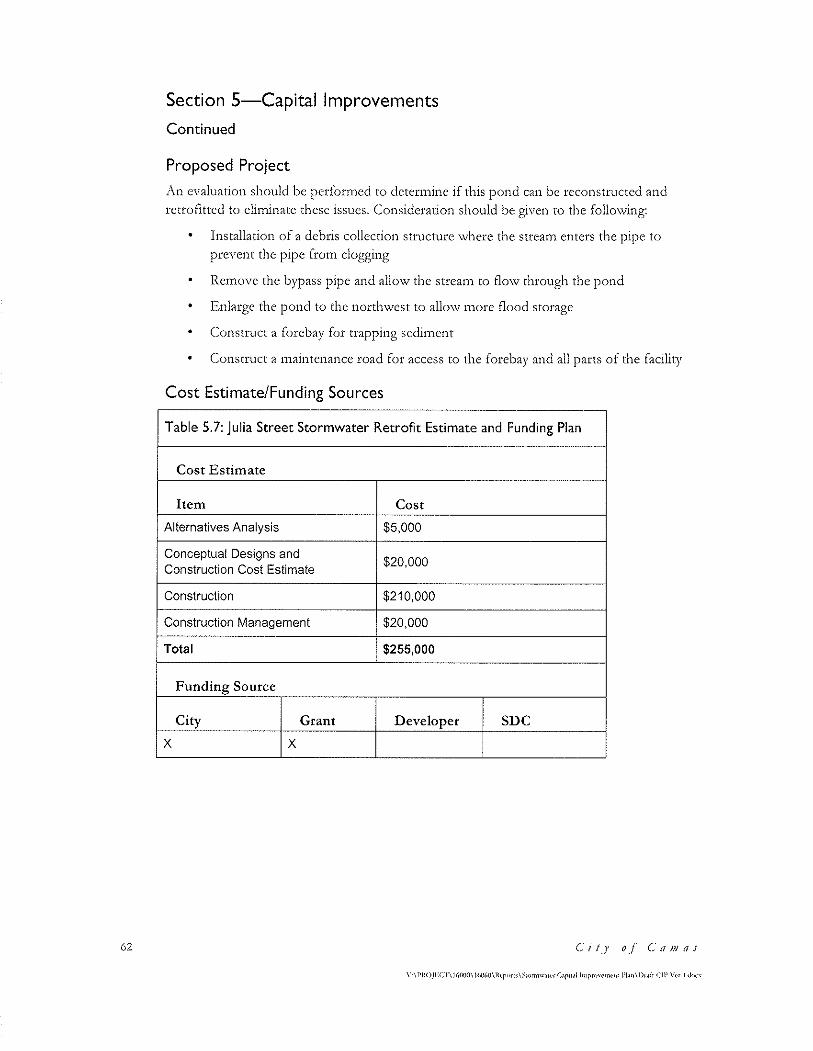
62
Section 5-Capital Improvements
Continued
Proposed Project
.r\n evaluation should be perfor1ned to dctcrn1inc if this pond can be reconstructed and retrofitted to clinlinate these issues. c:onsidcration should be given to the follo\ving:
Installation of a debris collection structure where the strea1n enters the pipe to prevent the pipe from clogging
•
Remove the bypass pipe and allow the stream to flow through the pond
12.nlargc the pond to the north\vest to allo\v inore flood storage
• c=onstruct a forcbay for trapping sedi1nent
Construct a 1naintenance road for access to the forebay and all parts of the facility
Cost Estimate/Funding Sources
Table 5.7: Julia Street Stormwater Retrofit Estimate and Funding Plan
Cost Estimate
Item Cost
Alternatives Analysis $5,000
Conceptual Designs and $20,000
Construction Cost Estimate
Construction $210,000
Construction Management $20,000
Total $255,000
Funding Source
City Grant Developer SDC
x x
c·il] o_f Ca1;;as
Y-\l'ltOJECT\!(,()(l(}\!W(,(l\lt,.p"m\,,;;nnnw.HNCap1t.ll ln1pr<J\'<'m<·n: l'l.1n\D1.1ft Cll' \'<·r ·I doc~
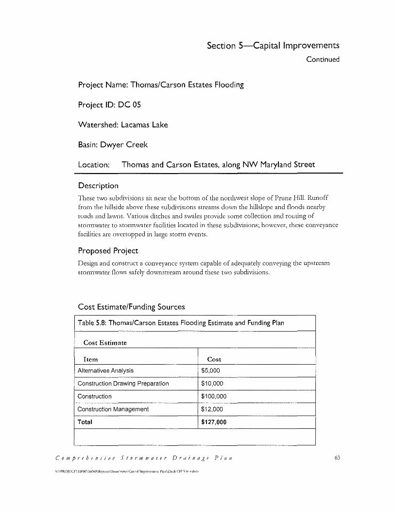
Section 5-Capital Improvements
Continued
Project Name: Thomas/Carson Estates Flooding
Project ID: DC 05
Watershed: Lacamas Lake
Basin: Dwyer Creek
Location: Thomas and Carson Estates, along NW Maryland Street
Description
These two subdivisions sit near the bottom of the northwest slope of Prune Hill. Runoff from the hillside above these subdivisions streams down the hillslopc and floods nearby roads and la\vns. \Tarious ditches and s\vales provide so1ne collection and routing of stortn'\vatcr to stortn\vater facilities located in these subdivisions; ho\vcver, these conveyance
facilities arc overtopped in large storm events.
Proposed Project
l)esign and construct a conveyance systc1n capable of adequately conveying the upstrca1n
stotmwatcr flo\VS safely do\vnstrcam around these t\VO subdivisions.
Cost Estimate/Funding Sources
Table 5.8: Thomas/Carson Estates Flooding Estimate and Funding Plan
Cost Estimate
Item Cost
Alternatives Analysis $5,000
Construction Drawing Preparation $10,000
Construction $100,000
Construction Management $12,000
Total $127,000
Co1J1prehe11sive Stor111J11ater Drai11r1~~e P/011
\':\l'HOJl'.Cf\l(i(IOO\ !6060\l\cporr>\~10mtw,HC< C.ojm.11 lmpro\·t•nwnl l'l.H1\Dr.d1 Cl!' \'r•r ·I do(x
63
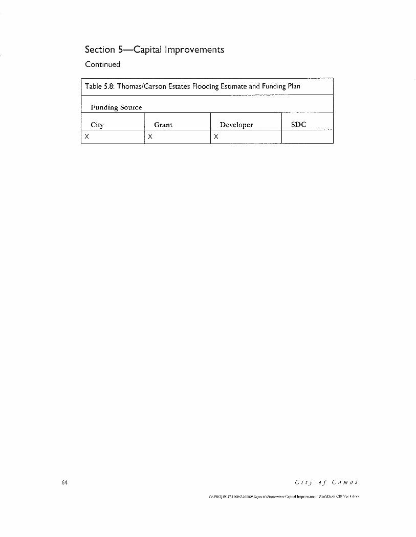
64
Section 5-Capital Improvements
Continued
Table 5.8: Thomas/Carson Estates Flooding Estimate and Funding Plan
Funding Source
City Grant Developer SDC
x x x
(' i 1)1 o./ (; tt IJJ as
Section 5-Capital Improvements
Continued
Project Name: North Urban Growth Area (NUGA) Stormwater Basin Plan
Project ID: ULB 0 I
Watershed: Lacamas Lake
Basin: Upper Lacamas Basin
Location: NUGA (North of Lacamas Lake)
Description
The City's urban growth boundary includes an area on the north side of Lacamas Lake called
the North Urban Growth Arca (NUGA). The NUGi\ is bounded by NW Leadbetter Road
and Lacamas Lake on the south, NE 232nd Avenue on the west, State Route 500/Everctt
Street on the cast, and varying roads and properties on the north. The City will be
developing a long-term plan for this area, including the establishment of detailed zoning and a street layout for arterials and collectors.
The city's planning effort for NUGJ\ includes development of a stormwatcr basin plan that
addresses water quality, flow control and conveyance. This plan will be designed to meet the
City's recently adopted stormwater ordinance that follows the Stormwatcr Management
Manual for Western Washington (SMM\1(1\'V').
The City's code exempts Lacamas Lake from flow control requirements if the following criteria are met:
'I'hc project site is drained by a conveyance systctn that is cotnpriscd entirely of
1nan1nade conveyance clen1cnts (e.g., pipes, ditches, outfall protection, etc.) and
extends to the ordinary high \Vatcr line of the exempt receiving \Vatcr; and
• T'he conveyance system bet\veen the project site and the exetnpt receiving water shall
have sufficient hydraulic capacity to convey discharges from future build-out
conditions (under current zoning) of the site, and the existing condition fro1n non
projcct areas from which runoff is or will be collected.
The conveyance systems for the NUGi\ area will be sized to carry undetained runoff so
detention of stormwatcr will not be required.
There are multiple culverts under Leadbetter Road that convey runoff from the north side of the road to l,aca1nas I .... ake. If these culverts can convey runoff fro1n the NUGA then flow
control facilities will not be required. This project will determine the capacity of these
c·o1J1prtht11sivt Stor1J1wa!er J)rai11age Plan 65
\'·\l'ltOJJ·'.C'J"\ 1MHlll\ 11,111,IJ\lkprn•<\~w"""".ll~r C.ip<t.ll lmpwwnwnt l'l.rn\Dr.1f1 Cll' \',,, 4 <l<>c'
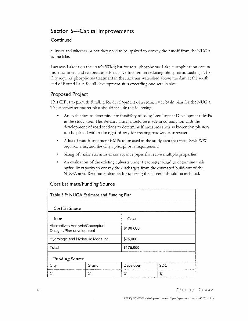
66
Section 5-Capital Improvements
Continued
culverts and whether or not they need to be upsizcd to convey the runoff fron1 the NUG1\
to the lake.
Lacamas Lake is on the state's 303(d) list for total phosphorus. Lake cutrophication occurs 1nost su1n1ncrs and restoration efforts have focused on reducing phosphorus loadings. 'fhe
C:ity requires phosphorus trcattncnt in the l,aca1nas \Vatershed above the <lain at the south
end of Round Lake for all devclopmen t sites exceeding one acre in size.
Proposed Project
'fhis Cil) is to provide funding for dcvclopn1cnt of a storn1\vatcr basin plan for the NLT(;,\,
The stormwater master plan should include the following:
•
An evaluation to determine the feasibility of using Low Impact Development BMPs in the study area. 'I'his detcr1nination should be n1adc in conjunction \vith the
dcvclop1nent of road sections to deter1nine if measures such as biorcntion planters
can be placed within the right-of-way for treating roadway stormwater.
A list of runoff treatment BMl's to be used in the study area that meet SM!V!\Xl\\I
rcquire1nents, and the c:iry's phosphorus rcquirctnent.
Sizing of 1najor stor1nwater conveyance pipes that serve 1nultiplc properties.
An evaluation of the existing culverts under Leadbetter Road to determine their
hydraulic capacity to convey the discharges from the estimated build-out of the
NUGA area. Recommendations for upsizing the culverts should be included.
Cost Estimate/Funding Source
Table 5.9: NUGA Estimate and Funding Plan
Cost Estimate
Item Cost
Alternatives Analysis/Conceptual $100,000
Designs/Plan development
Hydrologic and Hydraulic Modeling $75,000
Total $175,000
Funding Source
City Grant Developer SDC
x x x x
('it)' o_/ C'a111as
\" \l'ROJECT\!6()()(1\ J(,1)(;0\lfrporl>\~1ormw.nc1 C•i>H.•l lmptMt'mtm l'l.rn\Dr.ilr (Ip\·,,,- -l <lo"
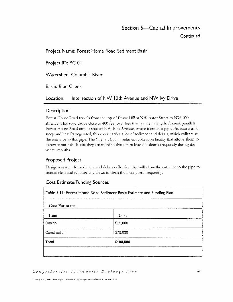
Section 5-Capital Improvements
Continued
Project Name: Forest Home Road Sediment Basin
Project ID: BC 0 I
Watershed: Columbia River
Basin: Blue Creek
Location: Intersection of NW I 0th Avenue and NW Ivy Drive
Description
Forest Home Road travels from the top of Prune Hill at NW Astor Street to NW 10th Avenue. This road drops close to 400 feet over less than a mile in length. J\ creek parallels I;'orest I~lome l\.oad until it reaches N\\l 10th ;\venue, \vhere it enters a pipe. Because it is so steep and heavily vegetated, this creek carries a lot of scdin1cnt and debris, \Vhich collects at
the entrance to this pipe. The City has built a sediment collection facility that allows them to excavate out this debris; they are called to this site to load out debris frequently during the \\rintcr n1onths.
Proposed Project
Design a system for sediment and debris collection that will allow the entrance to the pipe to rcn1ain clear and requires city crews to clean the facility less frequently.
Cost Estimate/Funding Sources
Table 5.1 I: Forest Home Road Sediment Basin Estimate and Funding Plan
Cost Estimate
Item Cost
Design $25,000
Construction $75,000
Total $100,000
C'o111j;rehe11sfpe Stor1111vr1ter Drai11age Plan 67
\'-\l'ROJl·:cn 161}\)()\ 160UO\lkp(nl;\$w,mw.m·r Copu.il lmprovcmcm l'l.in\Dr>fl (IP \'er -!.d<><"
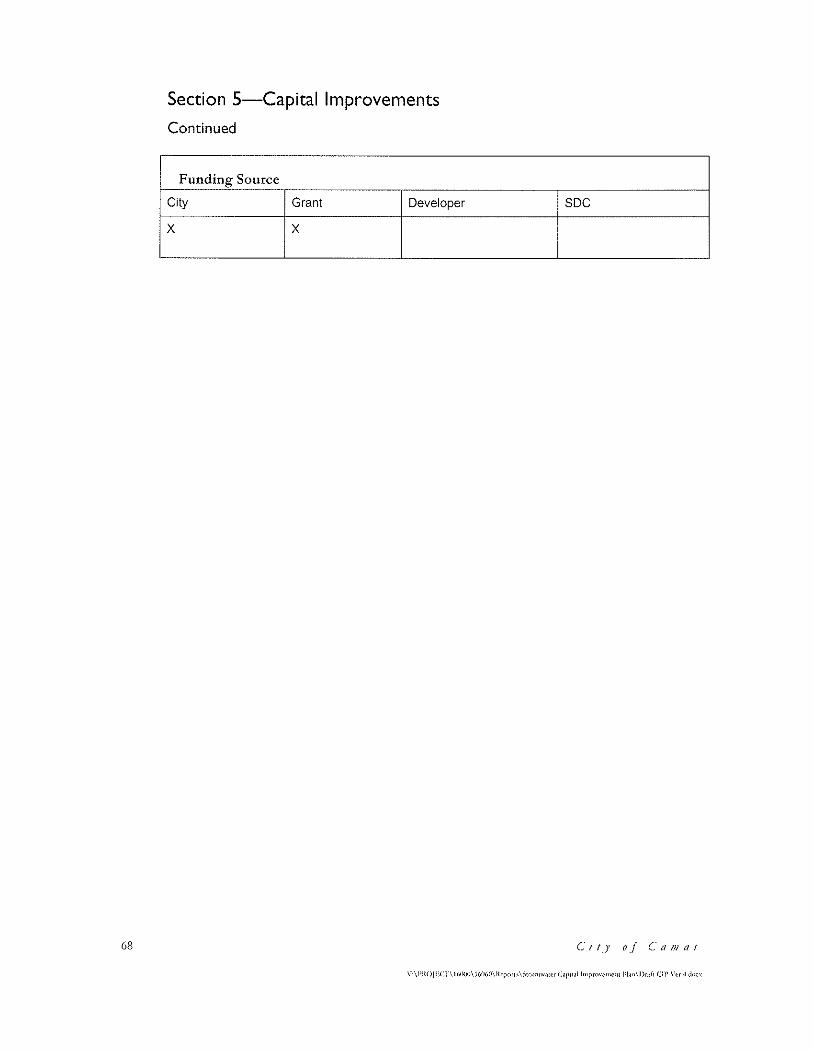
68
Section 5-Capital Improvements
Continued
Funding Source
City Grant Developer
x x soc
c-;,J' of C'tt!Jlt/S
\··\l'ltOJECT\l(,()(X)\)(,{l(,(l\lkport.,\Stnnllw,m•r Capa.1l lmpnw<·m<'f1! l'Lin\Dr.tft Cll' \"tr ·l dncx
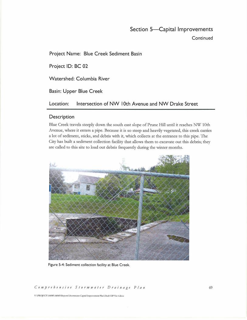
Section 5-Capital Improvements
Continued
Project Name: Blue Creek Sediment Basin
Project ID: BC 02
W atershed: Columbia River
Basin: Upper Blue C reek
Location: Intersection of NW I 0th Avenue and NW Drake Street
D escription
Blue Creek travels steeply down the south east slope o f Prune Hill until it reaches NW 10th Avenue, where it enters a pipe. Because it is so steep and heavily vegetated, this creek carries a lot of sediment, sticks, and debris with it, which collects at the en trance to this pipe. T he City has built a sediment collection facility that allows them to excavate out this debris; they are called to this site to load out debris frequently during the winter months.
Figure 5-4: Sediment collection facility at Blue Creek.
C on1pr e he11 s i v e Sto r n11vater D r a i 11age P/011 69
V:\PROJECr\16000\16060\Repons.\Stonnwatcr Cap1t<11 Improvement Pfan\ Dr.ift CIP Ver -1.docx
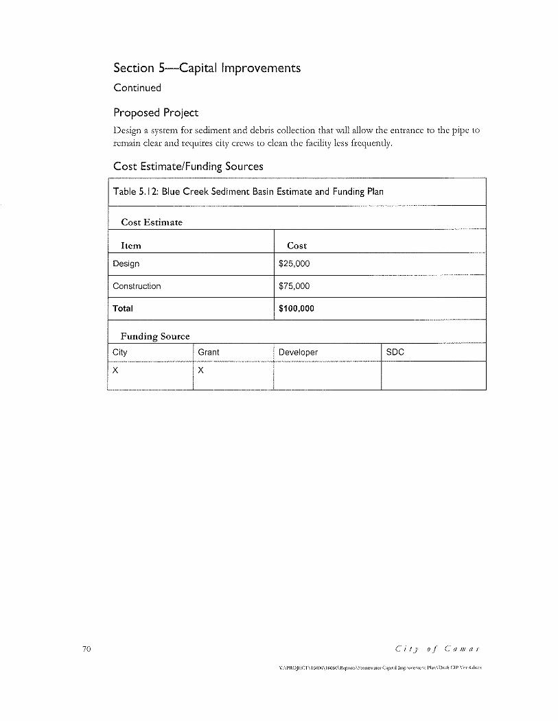
70
Section 5-Capital Improvements
Continued
Proposed Project
l)csign a systcn1 for scdin1cnt and debris collection that \Vill allo\v the entrance to the pipe to
remain clear and requires city crews to clean the facility less frequently.
Cost Estimate/Funding Sources
Table 5.12: Blue Creek Sediment Basin Estimate and Funding Plan
Cost Estimate
Item Cost
Design $25,000
Construction $75,000
Total $100,000
Funding Source
City Grant Developer soc x x
Ci!] o.l c-a/l/rlS
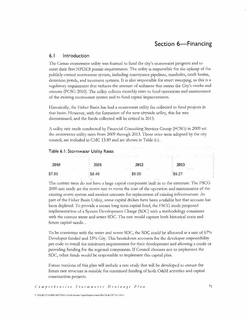
Section 6-Financing
6.1 Introduction
'I'hc (:a1nas StOflTI\VatCr utility \Vas formed tO fund the city's StOflTI\Vater progra1n and to
meet their first NPDES permit reguirements. The utility is responsible for the upkeep of the
publicly-o\vncd stortn\vater systc1n, including conveyance pipelines, manholes, catch basins,
detention ponds, and treatn1cnt syste1ns. It is also responsible for street SYvccping, as this is a regulatory requirc1ncnt that reduces the atnount of scditnent that enters the City's creeks and
streams (FCSG 2010). The utility collects monthly rates to fund operations and maintenance
of the existing storm\vater systctn and to fund capital in1prove1nents.
Historically, the Fisher Basin has had a stormwater utility fee collected to fund projects in
that basin. I-lo\vcver, with the formation of the nc'.-v cit)1'vide utility, this fee '.Vas
discontinued, and the funds collected will be retired in 2013.
A utility rate study conducted by Financial Consulting Services Group (FCSG) in 2009 set
the stonnwater utility rates from 2009 through 2013. Those rates were adopted by the city
council, arc included in Clv!C 13.89 and arc shown in Table 6.1.
Table 6.1: Stormwater Utility Rates
2010 2011 2012 2013
$7.65 $8.49 $9.00 $9.27
·rhc current rates do not have a large capital component built in to the structure. The r;·sc:c; 2009 rate study set the stor1n rate to cover the cost of the operation and maintenance of the
existing storn1 systcrn and n1odcst an1ounts for replacement of existing infrastructure. 1\s
part of the Fisher Basin lJtility, so1nc capital dollars have been available but that account has
been depleted. To provide a secure long term capital fund, the FSCG study proposed
implementation of a System Development Charge (SDC) with a methodology consistent
with the current water and sewer SDC. The rate would capture both historical costs and
funirc capital needs ..
To be consistent with the water and sewer SDC, the SDC: could be allocated at a rate of 67%
Developer funded and 33% City. This breakdown accounts for the developer responsibility per code to install the mini1nu1n rcquirc1nents for their dcveloptnent and allo\ving a credit or
providing funding for the regional component. If Council chooses not to implement the
SDC, other funds would be responsible to implement this capital plan.
Future versions of this plan will include a rate study that will be developed to ensure the
future rate structure is suitable for continued funding of both O&lvl activities and capital
construction projects.
C'o111prt'he11sitJe Stor1111vater Drai11a'-~e P!a11 71
72
Section 6-Financing
Continued
The city is scheduled to conduct a utility rate study in 2013. J\ policy decision should be 1nade on funding critical stonn\vatcr system capital needs through adoption of SDC's or
through rates. 'rhc utility currently has no debt associated \vith the rates.
C' i IJ of ('a 111 as
Section ?-References
Boornazian & Heare, 2008. Memorandum: Clarification on which stormwater infiltration practices/technologies have the potential to be regulated as "(]ass\!" \vclls by the Underground
Injection Control Program. United States Environmental Protection Agency. June 13, 2008.
FCSG 2010. City of Camas; Final Report for Utilities Rate Study. January 2010.
DEA 200l(a). Phase I Fisher Basin Stormwater and Wetlands Master Plan. David Evans and Associates. July 13, 2001. (Camas Project No. S-370).
DEA 2001(b). Technical Memorandum for Long-Term Assessment of North Dwyer Creek. David Evans and Associates. February, 2001. (Camas Project No. S-370).
DEA 1998. North D\\7er Creek Master Plan. Technical Memorandum #1: Inventory of Existing Conditions. David Evans and 1\ssociates. October 14, 1998. (Camas Project No. S-370).
Ecology 2006. Guidance for UIC Wells that Manage Stormwatcr. Washington State Department of Ecology. Publication Number 05-10-067. December 2006.
Washington Department of Ecology UJC Website. Retrieved.January 28'", 2013. http://www.eey.wa.gov/ programs/ wq/ grndwtr/ uic/ registration/ reginfo.html.
MF! 2005. Fisher Basin Hydrologic and Hydraulic Analysis. Maul, Foster, and Alongi. October 4, 2005. (Camas Project No. S-456).
C' i / )' 0 _( (' a Ill fl S 73
V:\PR()jJ~Cl"\ 16000\ 16060\Rcpons\Stormwaicr Capital lrnpron:mcnt Plan\Draf! CIP Ver 4.docx


Appendices


Appendix A
Storm Facilities Maintained by City

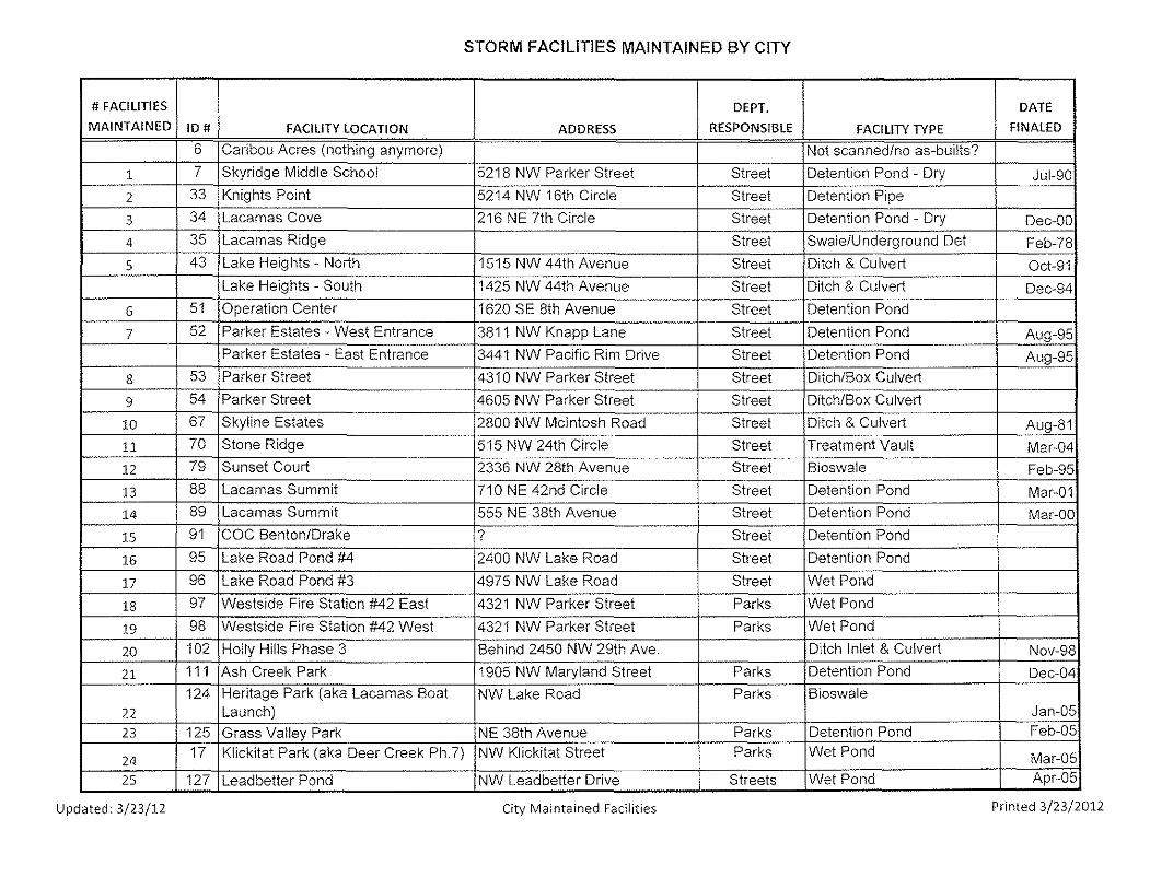
STORM FACILITIES MAINTAINED BY CITY
#FACILITIES DEPT. DATE
MAINTAINED ID# FACILITY LOCATION ADDRESS RESPONSIBLE FACILITY TYPE FINALED
6 Caribou Acres (nothing anymore) Not scanned/no as-builts?
1 7 Skyridge Middle School 5218 NW Parker Street Street Detention Pond - Dry Jul-90
2 33 Knights Point 5214 NW 16th Circle Street Detention Pipe
3 34 Lacamas Cove 216 NE 7th Circle Street Detention Pond - Dry Dec-OD
4 35 Lacamas Ridge Street Swale/Underground Det Feb-78
5 43 Lake Heights - North 1515 NW 44th Avenue Street Ditch & Culvert Oct-91 Lake Heights - South 1425 NW 44th Avenue Street Ditch & Culvert Dec-94
6 51 Operation Center 1620 SE 8th Avenue Street Detention Pond
7 52 Parker Estates - West Entrance 3811 NW Knapp Lane Street Detention Pond Aug-95 Parker Estates - East Entrance 3441 NW Pacific Rim Drive Street Detention Pond Aug-95
8 53 Parker Street 4310 NW Parker Street Street Ditch/Box Culvert
9 54 Parker Street 4605 NW Parker Street Street Ditch/Box Culvert
10 67 Skyline Estates 2800 NW Mcintosh Road Street Ditch & Culvert Aug-81
11 70 Stone Ridge 515 NW 24th Circle Street Treatment Vault Mar-04
12 79 Sunset Court 2336 NW 28th Avenue Street Bioswale Feb-95
13 88 Lacamas Summit 710 NE 42nd Circle Street Detention Pond Mar-01
14 89 Lacamas Summit 555 NE 38th Avenue Street Detention Pond Mar-00
15 91 COC Benton/Drake ? Street Detention Pond
16 95 Lake Road Pond #4 2400 NW Lake Road Street Detention Pond
17 96 Lake Road Pond #3 4975 NW Lake Road Street Wet Pond
18 97 Westside Fire Station #42 East 4321 NW Parker Street Parks Wet Pond
19 98 Westside Fire Station #42 West 4321 NW Parker Street Parks Wet Pond
20 102 Holly Hills Phase 3 Behind 2450 NW 29th Ave. Ditch Inlet & Culvert Nov-98
21 111 Ash Creek Park 1905 NW Maryland Street Parks Detention Pond Dec-04
124 Heritage Park (aka Lacamas Boat NW Lake Road Parks Bioswale 22 Launch) Jan-05
23 125 Grass Valley Park NE 38th Avenue Parks Detention Pond Feb-05
2~ 17 Klickitat Park (aka Deer Creek Ph.7) NW Klickitat Street Parks Wet Pond Mar-05
25 127 Leadbetter Pond NW Leadbetter Drive Streets Wet Pond Apr-05
Updated: 3/23/12 City Maintained Facilities Printed 3/23/2012


Appendix B
Cost Estimates

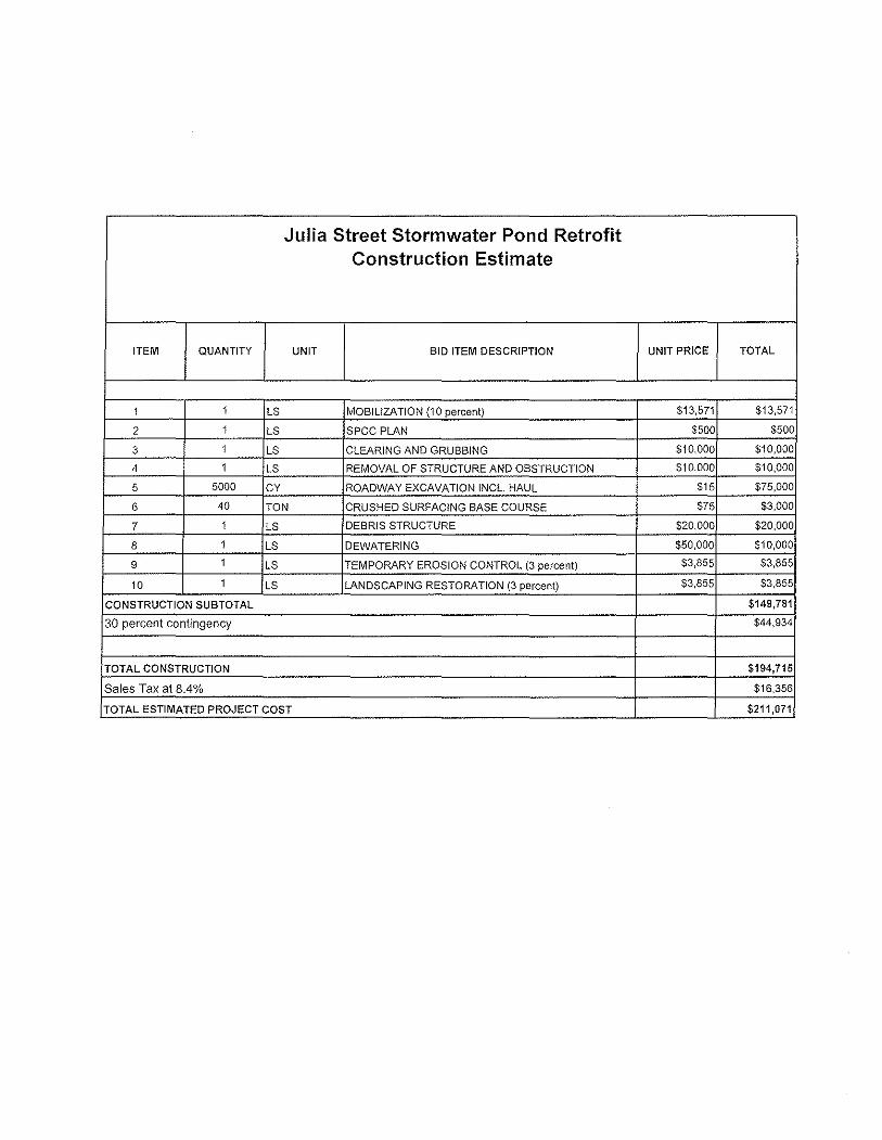
Julia Street Storrnwater Pond Retrofit Construction Estimate
ITEM QUANTITY UNIT BID ITEM DESCRIPTION UNIT PRICE TOTAL
1 1 LS MOBILIZATION {10 percent) $13,571 $13,571
2 1 LS SPCC PLAN $500 $500
3 1 LS CLEARING AND GRUBBING $10,000 $10,000
4 1 LS REMOVAL OF STRUCTURE AND OBSTRUCTION $10,000 $10,000
5 5000 CY ROADWAY EXCAVATION INCL HAUL $15 $75,000
6 40 TON CRUSHED SURFACING BASE COURSE $75 $3,000
7 1 LS DEBRIS STRUCTURE $20,000 $20,000
8 1 LS DEWATERING $50,000 $10,000
9 1 LS TEMPORARY EROSION CONTROL (3 percent) $3,855 $3,855
10 1 LS LANDSCAPING RESTORATION (3 percent) $3,855 $3,855
CONSTRUCTION SUBTOTAL $149,781
30 percent contingency $44,934
TOTAL CONSTRUCTION $194,715
Sales Tax at 8.4°/o $16,356
TOTAL ESTIMATED PROJECT COST $211,071
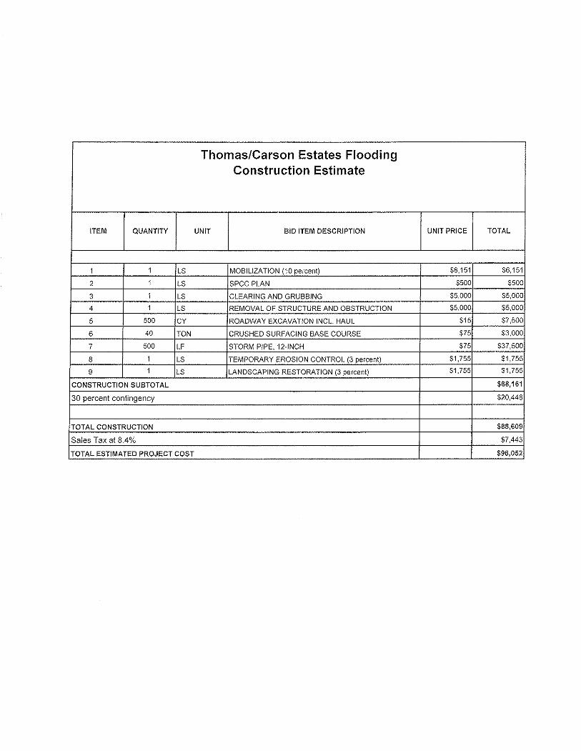
Thomas/Carson Estates Flooding Construction Estimate
ITEM QUANTITY UNIT BID ITEM DESCRIPTION UNIT PRICE TOTAL
1 1 LS MOBILIZATION (10 percent) $6,151 $6,151
2 1 LS SPCC PLAN $500 $500
3 1 LS CLEARING AND GRUBBING $5,000 $5,000
4 1 LS REMOVAL OF STRUCTURE AND OBSTRUCTION $5,000 55,000
5 500 CY ROADWAY EXCAVATION INCL. HAUL $15 $7,500
6 40 TON CRUSHED SURFACING BASE COURSE $75 $3,000
7 500 LF STORM PIPE, 12-INCH $75 $37,500
8 1 LS TEMPORARY EROSION CONTROL (3 percent) $1,755 $1,755
9 1 LS LANDSCAPING RESTORATION (3 percent) $1,755 $1,755
CONSTRUCTION SUBTOTAL $68,161
30 percent contingency $20,448
TOTAL CONSTRUCTION $88,609
Sales Tax at 8.4% $7,443
TOTAL ESTIMATED PROJECT COST $96,052
Appendix C
SEPA