composites: part b - missouri s&tweb.mst.edu/~vbirman/papers/tapered cylindrical cantilever...
TRANSCRIPT
Composites: Part B 42 (2011) 207–216
Contents lists available at ScienceDirect
Composites: Part B
journal homepage: www.elsevier .com/locate /composi tesb
Tapered cylindrical cantilever beam retrofitted with steel reinforced polymeror grout
Bryce L. Barton a, Mahesh S. Shetty a, Victor Birman a,b,⇑, Lokeswarappa R. Dharani a
a Department of Mechanical and Aerospace Engineering, Missouri University of Science and Technology, Rolla, MO 65409-0050, USAb Engineering Education Center, Missouri University of Science and Technology, One University Boulevard, St. Louis, MO 63121, USA
a r t i c l e i n f o
Article history:Received 3 June 2010Received in revised form 15 October 2010Accepted 20 October 2010Available online 26 October 2010
Keywords:Steel reinforced polymerB. StrengthB. DelaminationB. Damage tolerance
1359-8368/$ - see front matter � 2010 Elsevier Ltd. Adoi:10.1016/j.compositesb.2010.10.006
⇑ Corresponding author at: Engineering Education CScience and Technology, One University Boulevard, St+1 314 516 5436; fax: +1 314 516 5434.
E-mail address: [email protected] (V. Birman).
a b s t r a c t
The application of longitudinal steel reinforced polymer (SRP) or steel reinforced grout (SRG) strips torepair or strengthen electric transmission and distribution poles has been analytically modeled. The ana-lytical method developed in the paper is based on the theory of beams and accounts for the natural taperof wood poles. This method can also be applied to evaluate the effect of local damage due to mechanicalimpact, rot, woodpeckers, or other detrimental activities. The possibility of delamination of the SRP fromthe wood substrate was investigated experimentally. It appears, based on the tests, that delaminationdoes not represent the principal mode of failure for a wooden beam retrofitted with SRP. Numericalresults imply that the reinforcement of wooden poles with SRP leads to an enhanced stiffness, reducedstresses and a restoration of the load carrying capacity of a damaged pole.
� 2010 Elsevier Ltd. All rights reserved.
1. Introduction
Innovative and new solutions to extend the life cycle, increaseload carrying capacities, and repair structurally deficient electrictransmission and distribution poles has become increasinglyimportant as the nation’s electric utility infrastructure nears orsurpasses its designed life cycle. The average life expectancy of awood pole varies depending on species and environment, but typ-ically ranges around 30–40 years, with the possibility of extendingby additional 10–20 years or more with an effective maintenanceprogram [1]. In addition to natural degradation of poles due toaging, many poles are susceptible to damage due to mechanicalimpact, rot, insects, and woodpeckers. While the wood pole plantis one of the largest assets for most utility companies, many agingand damaged lines constructed shortly following World War II ap-proach or have already exceeded their anticipated life expectancy[2]. Increased structural demands are commonly encountereddue to progressively stringent loading requirements [3] and theneed for retrofitting existing lines with larger diameter conductorsto meet the ever-increasing demand for electric power.
Steel reinforced polymer (SRP) and steel reinforced grout (SRG)are two materials that are currently being investigated for retrofit-ting structures [4–8]. While these materials have predominantly
ll rights reserved.
enter, Missouri University of. Louis, MO 63121, USA. Tel.:
been applied to concrete and steel substrates, the application ofSRP to wood falls within the epoxy manufacturers recommendeduses [9]. Although numerical examples presented in this paperconsider wood as the pole material, the application of SRP or SRGto concrete or steel poles for additional structural capacity or re-pair will be investigated in the future utilizing a similar technique.
In this study, an analytical model has been developed to charac-terize the behavior of a pole modeled by a tapered cylindrical can-tilever beam retrofitted with externally bonded SRP and subjectedto a point load and/or uniformly distributed transverse load(approximating a wind load). A qualitative experimental programwas also conducted to determine whether a delamination of SRPfrom the wood substrate would be the eminent cause of failureof a wooden beam retrofitted with SRP. Although the numericalexamples are confined to SRP retrofitted beams, the present solu-tion is applicable to SRG repairs without any modifications.
2. Development of analytical model
The purpose of the analytical model developed in this paper isto characterize the behavior of a tapered cylindrical cantileveredbeam retrofitted with SRP. The analysis results in the stress atground line of a retrofitted structure so it may be compared tothe American National Standards Institute, Inc. (ANSI) specifica-tions for new poles to assess whether the strength ratings of agedor deteriorated poles could be restored by the application of SRP. Inaddition, the deflection of the retrofitted pole is quantified innumerical examples.
208 B.L. Barton et al. / Composites: Part B 42 (2011) 207–216
Specifications for wood pole dimensions and load carryingcapacities are given by ANSI 05.1 [10]. In this specification, the loadcarrying capacity of a wood pole is represented by the class of thepole. Wood poles of a given class are grouped based on the require-ment that a specified horizontal load placed two feet from the topof the pole should not produce a stress at ground line greater thanthe allowable fiber stress for the given material species. For exam-ple, a class 1 pole is required to have an ultimate bending capacityto support a horizontal load of 20.02 kN (4500 lbs) applied 2 ftfrom the top of the pole. Typical poles used in the construction
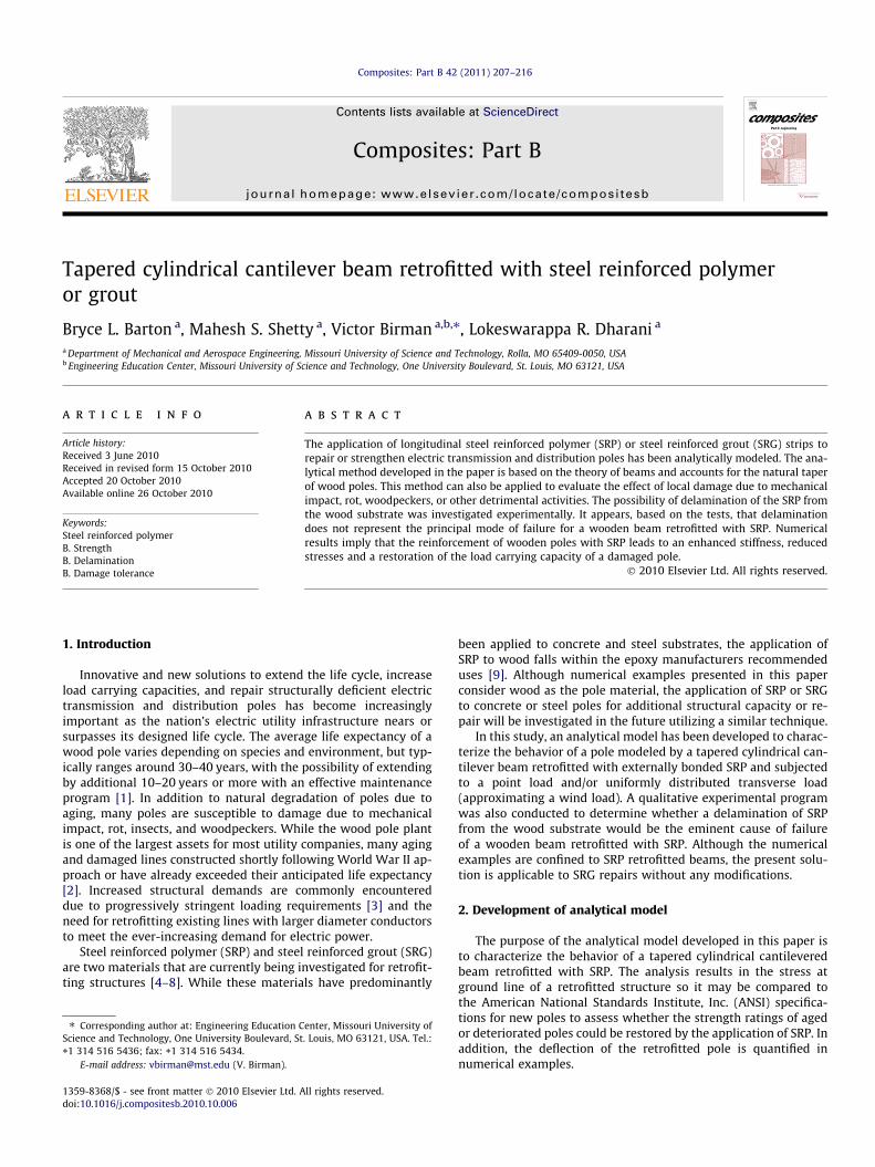
Fig. 1. Tapered cylindrical cantilevered beam subjected
of transmission and distribution lines can be modeled as havinga uniformly decreasing taper along the length of the pole.
The technical theory of beams is used to develop a piece-wisemodel of a cantilevered tapered cylindrical beam retrofitted withSRP or SRG subjected to a point load, P, and/or a uniform distrib-uted load, w (see Fig. 1). The point load is representative of theloads imposed on the pole due to the attached wires, and theuniform distributed load is representative of wind on the pole.For this analysis it is assumed that the length to diameter of thebeam is larger than 50, and therefore, effects of transverse shear
to a point load and/or uniformly distributed load.
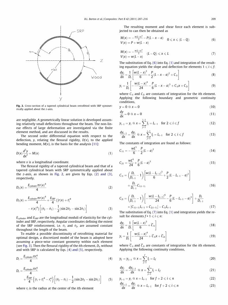
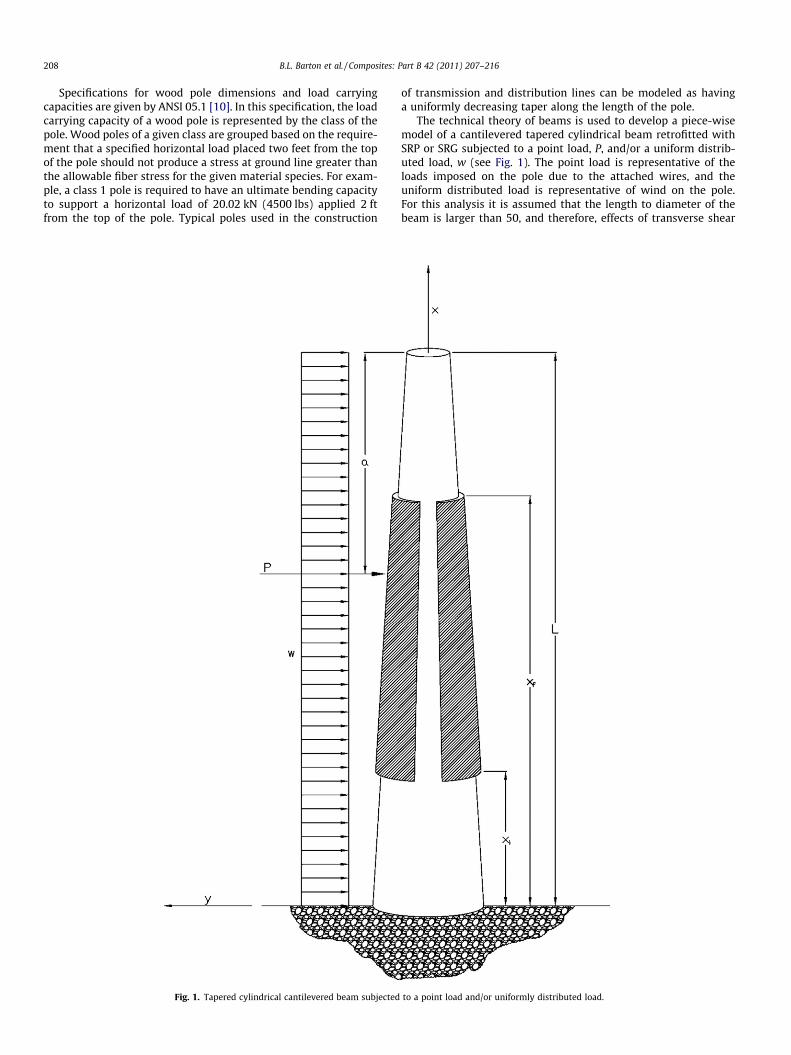
Fig. 2. Cross-section of a tapered cylindrical beam retrofitted with SRP symmet-rically applied about the z-axis.
B.L. Barton et al. / Composites: Part B 42 (2011) 207–216 209
are negligible. A geometrically linear solution is developed assum-ing relatively small deflections throughout the beam. The non-lin-ear effects of large deformation are investigated via the finiteelement method, and are discussed in the results.
The second order differential equation with respect to thedeflection, y, relating the flexural rigidity, D(x), to the appliedbending moment, M(x), is the basis for the analysis [11]:
DðxÞd2y
dx2 ¼ MðxÞ ð1Þ
where x is a longitudinal coordinate.The flexural rigidity of a tapered cylindrical beam and that of a
tapered cylindrical beam with SRP symmetrically applied aboutthe z-axis, as shown in Fig. 2, are given by Eqs. (2) and (3),respectively.
DzðxÞ ¼EcylinderprðxÞ4
4ð2Þ
DzðxÞ ¼EcylinderprðxÞ4
4þ ESRP
4f½rðxÞ þ t�4
� rðxÞ4g ðh2 � h1Þ �12ðsin 2h2 � sin 2h1Þ
� �ð3Þ
Ecylinder and ESRP are the longitudinal moduli of elasticity for the cyl-inder and SRP, respectively. Angular coordinates defining the extentof the SRP reinforcement, i.e. h1 and h2, are assumed constantthroughout the length of the beam.
To enable a possible discontinuity of retrofitting material foroptimal design, a discretized model of the beam is adopted hereassuming a piece-wise constant geometry within each element(see Fig. 3). Then the flexural rigidity of the ith element, Di, withoutand with SRP is calculated by Eqs. (4) and (5), respectively.
Di ¼Ecylinderpr4
i
4ð4Þ
Di ¼Ecylinderpr4
i
4
þ ESRP
4½ri þ t�4 � r4
i
n oðh2 � h1Þ �
12ðsin 2h2 � sin 2h1Þ
� �ð5Þ
where ri is the radius at the center of the ith element
The resulting moment and shear force each element is sub-jected to can then be obtained as
MðxÞ ¼ � wðL�xÞ22 � PðL� x� aÞ
VðxÞ ¼ P þwðL� xÞ0 6 x 6 ðL� QÞ ð6Þ
MðxÞ ¼ � wðL�xÞ22
VðxÞ ¼ wðL� xÞðL� QÞ 6 x 6 L ð7Þ
The substitution of Eq. (6) into Eq. (1) and integration of the result-ing equation yields the slope and deflection for elements 1 6 i 6 f:
dyi
dx¼ 1
Di
wðL� xÞ3
6þ P
2ðL� x� aÞ2 þ C1i
" #ð8Þ
yi ¼1Di�wðL� xÞ4
24� P
6ðL� x� aÞ3 þ C1ixþ C2i
" #ð9Þ
where C1i and C2i are constants of integration for the ith element.Applying the following boundary and geometric continuityconditions,
y ¼ 0 @ x ¼ 0 ð10Þdydx¼ 0 @ x ¼ 0 ð11Þ
yi�1 ¼ yi @ x ¼Xi�1
j¼1
lj ¼ Li�1 for 2 6 i 6 f ð12Þ
dyi�1
dx¼ dyi
dx@ x ¼
Xi�1
j¼1
lj ¼ Li�1 for 2 6 i 6 f ð13Þ
The constants of integration are found as follows:
C11 ¼ �wL3
6� P
2ðL� aÞ2 ð14Þ
C21 ¼wL4
24þ P
6ðL� aÞ3 ð15Þ
C1i ¼Di
Di�1� 1
� �wðL� Li�1Þ3
6þ P
2ðL� Li�1 � aÞ2
" #
þ Di
Di�1C1ði�1Þ ð16Þ
C2i ¼Di
Di�1� 1
� ��wðL� Li�1Þ4
24� P
6ðL� Li�1 � aÞ3
" #þ Di
Di�1
� ½C1ði�1ÞLi�1 þ C2ði�1Þ� � C1iLi�1 ð17ÞThe substitution of Eq. (7) into Eq. (1) and integration yields the re-sult for elements f + 1 6 i 6 n:
dyi
dx¼ 1
Di
wðL� xÞ3
6þ C1i
" #ð18Þ
yi ¼1Di�wðL� xÞ4
24þ C1ixþ C2i
" #ð19Þ
where C1i and C2i are constants of integration for the ith element.Applying the following continuity conditions,
yf ¼ yfþ1 @ x ¼Xf
j¼1
lj ¼ Lf ð20Þ
dyf
dx¼
dyfþ1
dx@ x ¼
Xf
j¼1
lj ¼ Lf ð21Þ
yi�1 ¼ yi @ x ¼ Li�1 for f þ 2 6 i 6 n ð22Þdyi�1
dx¼ dyi
dx@ x ¼ Li�1 for f þ 2 6 i 6 n ð23Þ
Fig. 3. Piece-wise cylindrical cantilevered beam subjected to a point load and/or uniformly distributed load.
Table 1Specimens used in delamination tests.
Specimens Description Qty
A1 & A2 Single SRP layer on tension side (staples on ends and 200
Spacing)2
B1 & B2 Single SRP layer on tension side (staples on ends) 2C1 & C2 Single SRP layer on tension side (no staples) 2D1 & D2 Control 2
210 B.L. Barton et al. / Composites: Part B 42 (2011) 207–216
The constants of integration are determined as
C1ðfþ1Þ ¼Dfþ1
Df� 1
� �wðL� Lf Þ3
6
" #
þ Dfþ1
Df
� �P2ðL� Lf � aÞ2 þ C1f
� �ð24Þ
C2ðfþ1Þ ¼Dfþ1
Df� 1
� ��wðL� Lf Þ4
24
" #
þ Dfþ1
Df
� �� P
6ðL� Lf � aÞ3 þ C1f Lf þ C2f
� �� C1ðfþ1ÞLf ð25Þ
C1i ¼Di
Di�1� 1
� �wðL� Li�1Þ3
6
" #þ Di
Di�1
� �C1ði�1Þ ð26Þ
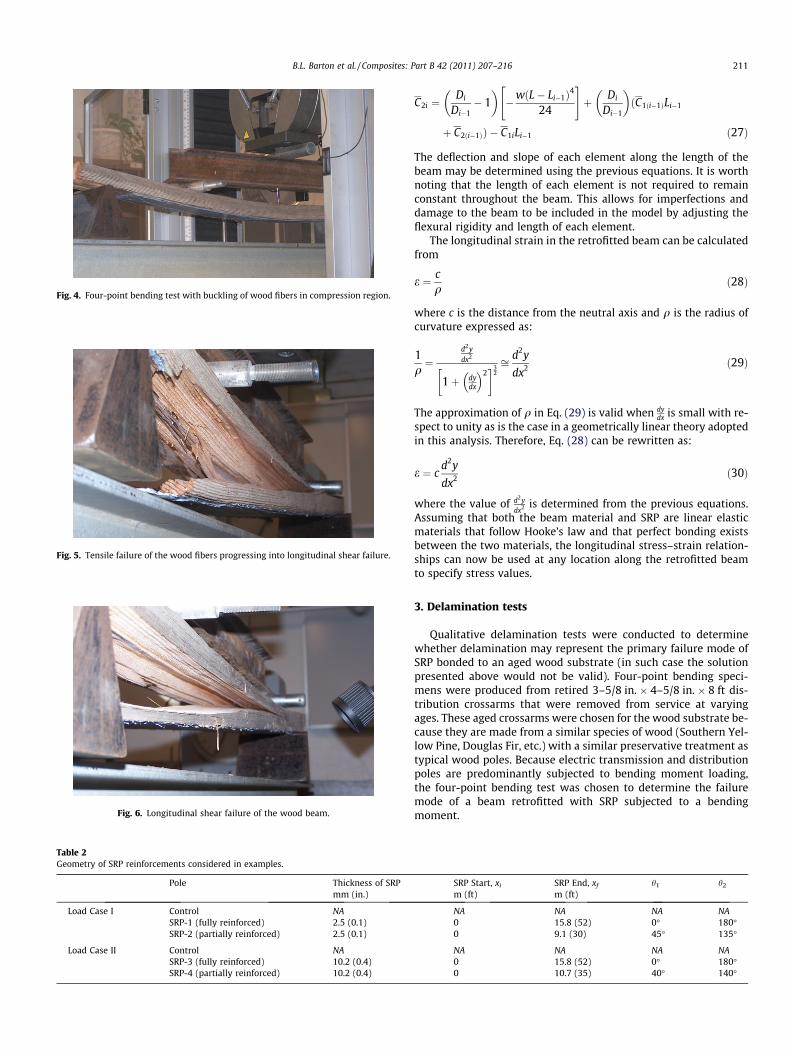
Fig. 4. Four-point bending test with buckling of wood fibers in compression region.
Fig. 5. Tensile failure of the wood fibers progressing into longitudinal shear failure.
Fig. 6. Longitudinal shear failure of the wood beam.
Table 2Geometry of SRP reinforcements considered in examples.
Pole Thickness of SRPmm (in.)
Load Case I Control NASRP-1 (fully reinforced) 2.5 (0.1)SRP-2 (partially reinforced) 2.5 (0.1)
Load Case II Control NASRP-3 (fully reinforced) 10.2 (0.4)SRP-4 (partially reinforced) 10.2 (0.4)
B.L. Barton et al. / Composites: Part B 42 (2011) 207–216 211
C2i ¼Di
Di�1� 1
� ��wðL� Li�1Þ4
24
" #þ Di
Di�1
� �ðC1ði�1ÞLi�1
þ C2ði�1ÞÞ � C1iLi�1 ð27Þ
The deflection and slope of each element along the length of thebeam may be determined using the previous equations. It is worthnoting that the length of each element is not required to remainconstant throughout the beam. This allows for imperfections anddamage to the beam to be included in the model by adjusting theflexural rigidity and length of each element.
The longitudinal strain in the retrofitted beam can be calculatedfrom
e ¼ cq
ð28Þ
where c is the distance from the neutral axis and q is the radius ofcurvature expressed as:
1q¼
d2ydx2
1þ dydx
� �2� �3
2ffi d2y
dx2 ð29Þ
The approximation of q in Eq. (29) is valid when dydx is small with re-
spect to unity as is the case in a geometrically linear theory adoptedin this analysis. Therefore, Eq. (28) can be rewritten as:
e ¼ cd2y
dx2 ð30Þ
where the value of d2ydx2 is determined from the previous equations.
Assuming that both the beam material and SRP are linear elasticmaterials that follow Hooke’s law and that perfect bonding existsbetween the two materials, the longitudinal stress–strain relation-ships can now be used at any location along the retrofitted beamto specify stress values.
3. Delamination tests
Qualitative delamination tests were conducted to determinewhether delamination may represent the primary failure mode ofSRP bonded to an aged wood substrate (in such case the solutionpresented above would not be valid). Four-point bending speci-mens were produced from retired 3–5/8 in. � 4–5/8 in. � 8 ft dis-tribution crossarms that were removed from service at varyingages. These aged crossarms were chosen for the wood substrate be-cause they are made from a similar species of wood (Southern Yel-low Pine, Douglas Fir, etc.) with a similar preservative treatment astypical wood poles. Because electric transmission and distributionpoles are predominantly subjected to bending moment loading,the four-point bending test was chosen to determine the failuremode of a beam retrofitted with SRP subjected to a bendingmoment.
SRP Start, xi SRP End, xf h1 h2
m (ft) m (ft)
NA NA NA NA0 15.8 (52) 0� 180�0 9.1 (30) 45� 135�
NA NA NA NA0 15.8 (52) 0� 180�0 10.7 (35) 40� 140�
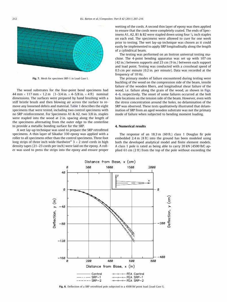
Fig. 7. Mesh for specimen SRP-1 in Load Case I.
212 B.L. Barton et al. / Composites: Part B 42 (2011) 207–216
The wood substrates for the four-point bend specimens had44 mm � 117 mm � 1.2 m (1–3/4 in. � 4–5/8 in. � 4 ft) nominaldimensions. The surfaces were prepared by hand brushing with astiff bristle brush and then blowing air across the surface to re-move any loosened debris and material. Table 1 describes the eightspecimens that were tested, including two control specimens withno SRP reinforcement. For Specimens A1 & A2, two 3/8 in. stapleswere stapled into the wood at 2 in. spacing along the length ofthe specimens alternating from the outer edge to the centerlineto provide a metallic bonding surface for the SRP.
A wet lay-up technique was used to prepare the SRP retrofittedspecimens. A thin layer of Sikadur 330 epoxy was applied with aroller to all specimens other than the control specimens. Three footlong strips of three inch wide Hardwire� 3 � 2 steel cords in highdensity tapes (21–23 cords per inch) were laid on the epoxy. A roll-er was used to press the strips into the epoxy and ensure proper
Fig. 8. Deflection of a SRP retrofitted pole subje
wetting of the cords. A second thin layer of epoxy was then appliedto ensure that the cords were completely coated. The ends of Spec-imens A1, A2, B1 & B2 were stapled down using four 3=4 inch stapleson each end. The specimens were allowed to cure for one weekprior to testing. The wet lay-up technique was chosen as it couldeasily be implemented to apply SRP longitudinally along the lengthof a cylindrical beam.
The testing was performed on an Instron universal testing ma-chine. The 4-point bending apparatus was set up with 107 cm(42 in.) between supports and 23 cm (9 in.) between each supportand load point. Testing was conducted with a crosshead speed of0.5 cm per minute (0.2 in. per minute). Data was recorded at thefrequency of 10 Hz.
The primary modes of failure encountered during testing werebuckling of the wood on the compression side of the beam, tensilefailure of the wooden fibers, and longitudinal shear failure of thewood, i.e. failure along the grain of the wood, as shown in Figs.4–6, respectively. The onset of some failures occurred at the bolthole locations on the tension side of the beam. However, even withthe stress concentration around the holes, no delamination of theSRP was observed. These tests qualitatively illustrated that delam-ination of SRP from an aged wooden substrate was not the primarymode of failure when subjected to bending moment loading.
4. Numerical results
The response of an 18.3 m (60 ft.) class 1 Douglas fir poleembedded 2.4 m (8 ft) into the ground has been modeled usingboth the developed analytical model and finite element models.A class 1 pole is rated as being able to carry 20 kN (4500 lbf) ap-plied 61 cm (2 ft) from the top of the pole without exceeding the
cted to a 4500 lbf point load (Load Case I).
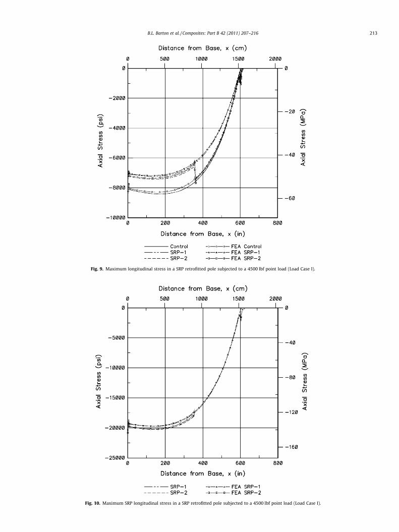
Fig. 9. Maximum longitudinal stress in a SRP retrofitted pole subjected to a 4500 lbf point load (Load Case I).
Fig. 10. Maximum SRP longitudinal stress in a SRP retrofitted pole subjected to a 4500 lbf point load (Load Case I).
B.L. Barton et al. / Composites: Part B 42 (2011) 207–216 213
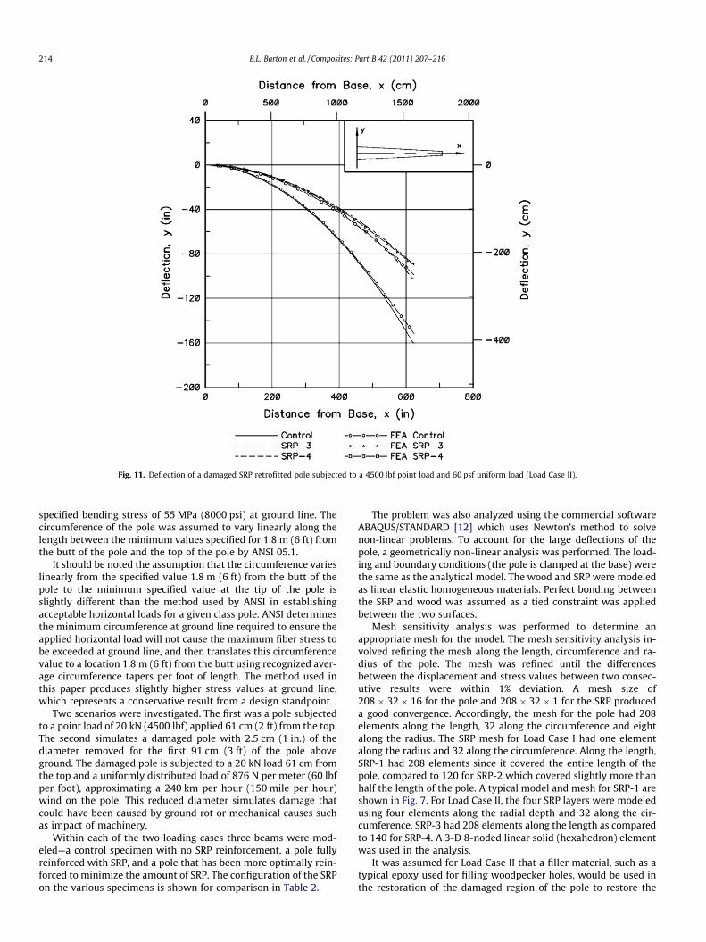
Fig. 11. Deflection of a damaged SRP retrofitted pole subjected to a 4500 lbf point load and 60 psf uniform load (Load Case II).
214 B.L. Barton et al. / Composites: Part B 42 (2011) 207–216
specified bending stress of 55 MPa (8000 psi) at ground line. Thecircumference of the pole was assumed to vary linearly along thelength between the minimum values specified for 1.8 m (6 ft) fromthe butt of the pole and the top of the pole by ANSI 05.1.
It should be noted the assumption that the circumference varieslinearly from the specified value 1.8 m (6 ft) from the butt of thepole to the minimum specified value at the tip of the pole isslightly different than the method used by ANSI in establishingacceptable horizontal loads for a given class pole. ANSI determinesthe minimum circumference at ground line required to ensure theapplied horizontal load will not cause the maximum fiber stress tobe exceeded at ground line, and then translates this circumferencevalue to a location 1.8 m (6 ft) from the butt using recognized aver-age circumference tapers per foot of length. The method used inthis paper produces slightly higher stress values at ground line,which represents a conservative result from a design standpoint.
Two scenarios were investigated. The first was a pole subjectedto a point load of 20 kN (4500 lbf) applied 61 cm (2 ft) from the top.The second simulates a damaged pole with 2.5 cm (1 in.) of thediameter removed for the first 91 cm (3 ft) of the pole aboveground. The damaged pole is subjected to a 20 kN load 61 cm fromthe top and a uniformly distributed load of 876 N per meter (60 lbfper foot), approximating a 240 km per hour (150 mile per hour)wind on the pole. This reduced diameter simulates damage thatcould have been caused by ground rot or mechanical causes suchas impact of machinery.
Within each of the two loading cases three beams were mod-eled—a control specimen with no SRP reinforcement, a pole fullyreinforced with SRP, and a pole that has been more optimally rein-forced to minimize the amount of SRP. The configuration of the SRPon the various specimens is shown for comparison in Table 2.
The problem was also analyzed using the commercial softwareABAQUS/STANDARD [12] which uses Newton’s method to solvenon-linear problems. To account for the large deflections of thepole, a geometrically non-linear analysis was performed. The load-ing and boundary conditions (the pole is clamped at the base) werethe same as the analytical model. The wood and SRP were modeledas linear elastic homogeneous materials. Perfect bonding betweenthe SRP and wood was assumed as a tied constraint was appliedbetween the two surfaces.
Mesh sensitivity analysis was performed to determine anappropriate mesh for the model. The mesh sensitivity analysis in-volved refining the mesh along the length, circumference and ra-dius of the pole. The mesh was refined until the differencesbetween the displacement and stress values between two consec-utive results were within 1% deviation. A mesh size of208 � 32 � 16 for the pole and 208 � 32 � 1 for the SRP produceda good convergence. Accordingly, the mesh for the pole had 208elements along the length, 32 along the circumference and eightalong the radius. The SRP mesh for Load Case I had one elementalong the radius and 32 along the circumference. Along the length,SRP-1 had 208 elements since it covered the entire length of thepole, compared to 120 for SRP-2 which covered slightly more thanhalf the length of the pole. A typical model and mesh for SRP-1 areshown in Fig. 7. For Load Case II, the four SRP layers were modeledusing four elements along the radial depth and 32 along the cir-cumference. SRP-3 had 208 elements along the length as comparedto 140 for SRP-4. A 3-D 8-noded linear solid (hexahedron) elementwas used in the analysis.
It was assumed for Load Case II that a filler material, such as atypical epoxy used for filling woodpecker holes, would be used inthe restoration of the damaged region of the pole to restore the
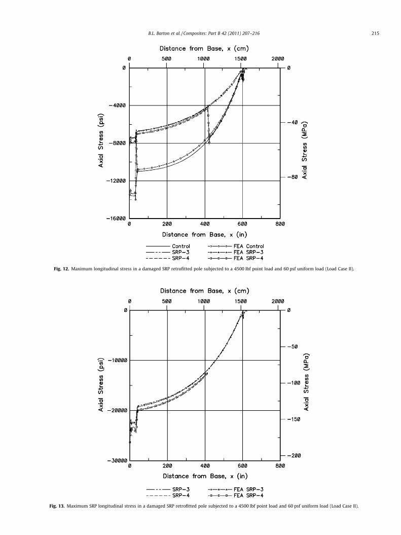
Fig. 12. Maximum longitudinal stress in a damaged SRP retrofitted pole subjected to a 4500 lbf point load and 60 psf uniform load (Load Case II).
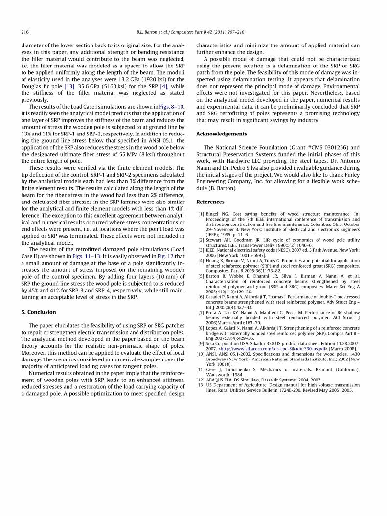
Fig. 13. Maximum SRP longitudinal stress in a damaged SRP retrofitted pole subjected to a 4500 lbf point load and 60 psf uniform load (Load Case II).
B.L. Barton et al. / Composites: Part B 42 (2011) 207–216 215
216 B.L. Barton et al. / Composites: Part B 42 (2011) 207–216
diameter of the lower section back to its original size. For the anal-yses in this paper, any additional strength or bending resistancethe filler material would contribute to the beam was neglected,i.e. the filler material was modeled as a spacer to allow the SRPto be applied uniformly along the length of the beam. The moduliof elasticity used in the analyses were 13.2 GPa (1920 ksi) for theDouglas fir pole [13], 35.6 GPa (5160 ksi) for the SRP [4], whilethe stiffness of the filler material was neglected as statedpreviously.
The results of the Load Case I simulations are shown in Figs. 8–10.It is readily seen the analytical model predicts that the application ofone layer of SRP improves the stiffness of the beam and reduces theamount of stress the wooden pole is subjected to at ground line by13% and 11% for SRP-1 and SRP-2, respectively. In addition to reduc-ing the ground line stress below that specified in ANSI 05.1, theapplication of the SRP also reduces the stress in the wood pole belowthe designated ultimate fiber stress of 55 MPa (8 ksi) throughoutthe entire length of pole.
These results were verified via the finite element models. Thetip deflection of the control, SRP-1 and SRP-2 specimens calculatedby the analytical models each had less than 3% difference from thefinite element results. The results calculated along the length of thebeam for the fiber stress in the wood had less than 2% difference,and calculated fiber stresses in the SRP laminas were also similarfor the analytical and finite element models with less than 1% dif-ference. The exception to this excellent agreement between analyt-ical and numerical results occurred where stress concentrations orend effects were present, i.e., at locations where the point load wasapplied or SRP was terminated. These effects were not included inthe analytical model.
The results of the retrofitted damaged pole simulations (LoadCase II) are shown in Figs. 11–13. It is easily observed in Fig. 12 thata small amount of damage at the base of a pole significantly in-creases the amount of stress imposed on the remaining woodenpole of the control specimen. By adding four layers (10 mm) ofSRP the ground line stress the wood pole is subjected to is reducedby 45% and 41% for SRP-3 and SRP-4, respectively, while still main-taining an acceptable level of stress in the SRP.
5. Conclusion
The paper elucidates the feasibility of using SRP or SRG patchesto repair or strengthen electric transmission and distribution poles.The analytical method developed in the paper based on the beamtheory accounts for the realistic non-prismatic shape of poles.Moreover, this method can be applied to evaluate the effect of localdamage. The scenarios considered in numerical examples cover themajority of anticipated loading cases for tangent poles.
Numerical results obtained in the paper imply that the reinforce-ment of wooden poles with SRP leads to an enhanced stiffness,reduced stresses and a restoration of the load carrying capacity ofa damaged pole. A possible optimization to meet specified design
characteristics and minimize the amount of applied material canfurther enhance the design.
A possible mode of damage that could not be characterizedusing the present solution is a delamination of the SRP or SRGpatch from the pole. The feasibility of this mode of damage was in-spected using delamination testing. It appears that delaminationdoes not represent the principal mode of damage. Environmentaleffects were not investigated for this paper. Nevertheless, basedon the analytical model developed in the paper, numerical resultsand experimental data, it can be preliminarily concluded that SRPand SRG retrofitting of poles represents a promising technologythat may result in significant savings by industry.
Acknowledgements
The National Science Foundation (Grant #CMS-0301256) andStructural Preservation Systems funded the initial phases of thiswork, with Hardwire LLC providing the steel tapes. Dr. AntonioNanni and Dr. Pedro Silva also provided invaluable guidance duringthe initial stages of the project. We would also like to thank FinleyEngineering Company, Inc. for allowing for a flexible work sche-dule (B. Barton).
References
[1] Bingel NG. Cost saving benefits of wood structure maintenance. In:Proceedings of the 7th IEEE international conference of transmission anddistribution construction and live line maintenance, Columbus, Ohio, October29–November 3. New York: Institute of Electrical and Electronics Engineers(IEEE); 1995. p. 11–6.
[2] Stewart AH, Goodman JR. Life cycle of economics of wood pole utilitystructures. IEEE Trans Power Deliv 1990;5(2):1040–6.
[3] IEEE. National electrical safety code (NESC). 2007 ed. 3 Park Avenue, New York;2006 [New York 10016-5997].
[4] Huang X, Birman V, Nanni A, Tunis G. Properties and potential for applicationof steel reinforced polymer (SRP) and steel reinforced grout (SRG) composites.Composites, Part B 2005;36(1):73–82.
[5] Barton B, Wobbe E, Dharani LR, Silva P, Birman V, Nanni A, et al.Characterization of reinforced concrete beams strengthened by steelreinforced polymer and grout (SRP and SRG) composites. Mater Sci Eng A2005;412(1-2):129–36.
[6] Casadei P, Nanni A, Alkhrdaji T, Thomas J. Performance of double-T prestressedconcrete beams strengthened with steel reinforced polymer. Adv Struct Eng –Int J 2005;8(4):427–42.
[7] Prota A, Tan KY, Nanni A, Manfredi G, Pecce M. Performance of RC shallowbeams externally bonded with steel reinforced polymer. ACI Struct J2006(March–April):163–70.
[8] Lopez A, Galati N, Nanni A, Alkhrdaji T. Strengthening of a reinforced concretebridge with externally bonded steel reinforced polymer (SRP). Compos Part B –Eng 2007;38(4):429–36.
[9] Sika Corporation USA. Sikadur 330 US product data sheet, Edition 11.28.2007;2007. <http://www.sikacorp.com/tds-cpd-Sikadur330-us.pdf> [March 2008].
[10] ANSI. ANSI 05.1-2002, Specifications and dimensions for wood poles. 1430Broadway (New York): American National Standards Institute, Inc.; 2002 [NewYork 10018].
[11] Gere J, Timoshenko S. Mechanics of materials. Belmont (California):Wadsworth; 1984.
[12] ABAQUS FEA, DS Simulia�, Dassault Systems; 2004, 2007.[13] US Department of Agriculture. Design manual for high voltage transmission
lines. Rural Utilities Service Bulletin 1724E-200. Revised May 2005; 2005.