composite shear walls with encased profiles, new solution...
TRANSCRIPT

Acta Technica Napocensis: Civil Engineering & Architecture Vol. 54 No.1 (2011) Journal homepage: http://constructii.utcluj.ro/ActaCivilEng
Composite Shear Walls with Encased Profiles, New Solution for
Buildings Placed in Seismic Area
V. Stoian *1, D. Dan1, A. Fabian1
1 Politehnica University of Timisoata, Faculty of Civil Engineering, Department of Civil Engineering, Timisoara, Romania
Received 29 May 2011; Accepted 15 August 2011
Abstract
The concrete advantages in terms of higher stiffness, good fire protection, buckling prevention, recommends composite elements made by steel and concrete to be used in high-rise buildings placed in seismic areas. The steel concrete composite shear walls are used as lateral loads resisting systems for high-rise buildings as an alternative to reinforced concrete shear walls. Composite steel concrete shear walls are structural walls where at the boundary elements of the wall are encased steel profiles. The information’s about this type of elements are poor also in the literature and in the design provisions for composite structures and for structures subjected to lateral loads from earthquake. A research program is in ongoing process at the Department of Civil Engineering from Politehnica University of Timisoara, which studies the behavior of composite steel concrete shear walls under cyclic lateral loads. Six scaled experimental elements were tested in laboratory under combined vertical and cyclic lateral loads. The paper presents the behavior of the experimental elements under lateral loads including the strain analysis in structural steel and reinforcements and the failure modes experienced by all tested elements. The results obtained during the experimental tests shown that the behavior of composite steel concrete shear walls is a ductile one, no brittle failure being experienced by the tested elements.
Rezumat
Avantajele betonului în termeni de rigiditate sporitူ, asigurare a protecᘰiei la foc ᗰi împiedecare a flambajului, recomandူ utilizarea elementelor compozite oᘰel beton la realizarea clူdirilor înalte amplasate în zone seismice. Pereᘰii structurali compoziᘰi oᘰel beton sunt utilizaᘰi ca alternativူ a pereᘰilor structurali din beton armat în cadrul sistemelor structurale acᘰionate preponderent de încူrcူri laterale. Pereᘰii structurali compoziᘰi structurali sunt pereᘰi din beton armat cu profile metalice înglobate la capete. Informaᘰiile legate de acest tip de element structural sunt reduse în normele de proiectare pentru elemente compozite oᘰel beton cât ᗰi în normele referitoare la proiectarea structurilor la cutremur. Un program de cercetare este în derulare la Departamentul de Construcᘰii Civile din cadrul Universitူᘰii Politehnica din Timiᗰoara ᗰi are ca scopr studiul comportူrii pereᘰilor compoziᘰi oᘰel beton supuᗰi acᘰiunilor laterale ciclice. ᗠase elemente experimentale supuse unor acᘰiuni verticale constante ᗰi unor orizontale ciclice au fost testate în laborator. Lucrarea de faᘰူ prezintူ comportarea elementelor experimentale supuse la acᘰiunea combinatူ a încူrcူrilor verticale ᗰi orizontale cu accent pe analiza deformaᘰiilor specifice din oᘰelul structural ᗰi armူturi precum ᗰi a modurilor de cedare ale elementelor testate. Rezultatele obᘰinute aratူ cူ pereᘰii structurali compoziᘰi oᘰel beton au o comportare ductilူ. * Corresponding author: Tel./ Fax.: 40 256 403 952 / +40 256 403 958 E-mail address: [email protected]
V. Stoian et al / Acta Technica Napocensis: Civil Engineering & Architecture Vol. 54 No.1 (2011) 6-12
6
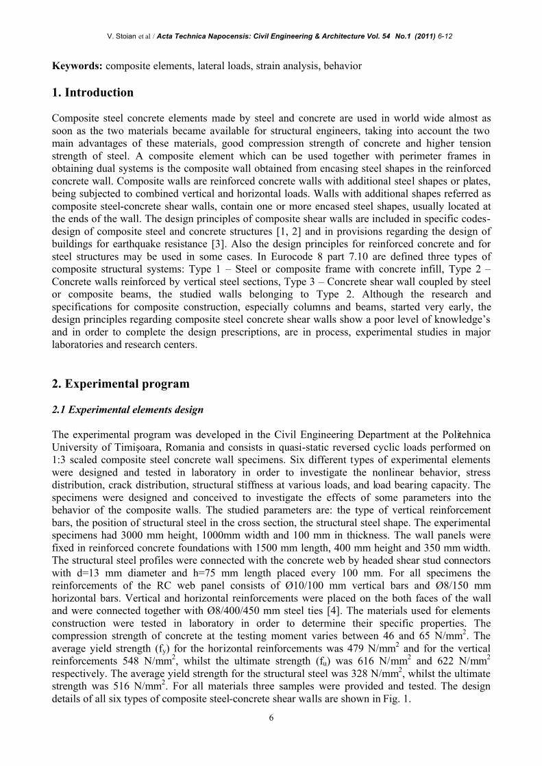
Keywords: composite elements, lateral loads, strain analysis, behavior 1. Introduction Composite steel concrete elements made by steel and concrete are used in world wide almost as soon as the two materials became available for structural engineers, taking into account the two main advantages of these materials, good compression strength of concrete and higher tension strength of steel. A composite element which can be used together with perimeter frames in obtaining dual systems is the composite wall obtained from encasing steel shapes in the reinforced concrete wall. Composite walls are reinforced concrete walls with additional steel shapes or plates, being subjected to combined vertical and horizontal loads. Walls with additional shapes referred as composite steel-concrete shear walls, contain one or more encased steel shapes, usually located at the ends of the wall. The design principles of composite shear walls are included in specific codes-design of composite steel and concrete structures [1, 2] and in provisions regarding the design of buildings for earthquake resistance [3]. Also the design principles for reinforced concrete and for steel structures may be used in some cases. In Eurocode 8 part 7.10 are defined three types of composite structural systems: Type 1 – Steel or composite frame with concrete infill, Type 2 – Concrete walls reinforced by vertical steel sections, Type 3 – Concrete shear wall coupled by steel or composite beams, the studied walls belonging to Type 2. Although the research and specifications for composite construction, especially columns and beams, started very early, the design principles regarding composite steel concrete shear walls show a poor level of knowledge’s and in order to complete the design prescriptions, are in process, experimental studies in major laboratories and research centers. 2. Experimental program 2.1 Experimental elements design The experimental program was developed in the Civil Engineering Department at the Politehnica University of Timiᗰoara, Romania and consists in quasi-static reversed cyclic loads performed on 1:3 scaled composite steel concrete wall specimens. Six different types of experimental elements were designed and tested in laboratory in order to investigate the nonlinear behavior, stress distribution, crack distribution, structural stiffness at various loads, and load bearing capacity. The specimens were designed and conceived to investigate the effects of some parameters into the behavior of the composite walls. The studied parameters are: the type of vertical reinforcement bars, the position of structural steel in the cross section, the structural steel shape. The experimental specimens had 3000 mm height, 1000mm width and 100 mm in thickness. The wall panels were fixed in reinforced concrete foundations with 1500 mm length, 400 mm height and 350 mm width. The structural steel profiles were connected with the concrete web by headed shear stud connectors with d=13 mm diameter and h=75 mm length placed every 100 mm. For all specimens the reinforcements of the RC web panel consists of Ø10/100 mm vertical bars and Ø8/150 mm horizontal bars. Vertical and horizontal reinforcements were placed on the both faces of the wall and were connected together with Ø8/400/450 mm steel ties [4]. The materials used for elements construction were tested in laboratory in order to determine their specific properties. The compression strength of concrete at the testing moment varies between 46 and 65 N/mm2. The average yield strength (fy) for the horizontal reinforcements was 479 N/mm2 and for the vertical reinforcements 548 N/mm2, whilst the ultimate strength (fu) was 616 N/mm2 and 622 N/mm2 respectively. The average yield strength for the structural steel was 328 N/mm2, whilst the ultimate strength was 516 N/mm2. For all materials three samples were provided and tested. The design details of all six types of composite steel-concrete shear walls are shown in Fig. 1.

V. Stoian et al / Acta Technica Napocensis: Civil Engineering & Architecture Vol. 54 No.1 (2011) 6-12
7
h=30
00
Partially encasedU10 steel profile
Longitudinal reinforcementsØ10@100
Headed shearstud connectorØ13x75
50 70 760 70 50
b=1000
Horizontal reinforcementsØ8@150
HoopsØ8@150
50
U shape connector
HoopsØ8@150
Horizontal reinforcementsØ8@150
Ø10@100
U shape connectorØ8/100
15 7015100
100
100
100
100
150
150
53
Headed shearstud connectorØ13x75
A A
150
150
a) Elevation
horizontal reinforcementØ8@150
shear connectorØ13@150
steel encased profile70x70x5
vertical reinforcementØ10@100
CSRCW-1
CSRCW-2
CSRCW-3
CSRCW-4
CSRCW-6
CSRCW-5
100
1178
1111
7811
1178
1111
7811
1178
1111
7811
100100
100100
100
7070
7070
steel encased profile(70x70x5)
vertical reinforcementØ10@25
50 70 760 70 50
50 70 760 70 50
1000
50 70 345 70 345 70 50
50 70 760 70 50
1000
70 860 70
1000
b) A-A Sections
Figure 1. Details of the composite steel-concrete walls

V. Stoian et al / Acta Technica Napocensis: Civil Engineering & Architecture Vol. 54 No.1 (2011) 6-12
8
2.2 Test set-up and instrumentation All specimens were tested under constant vertical load and cyclically increasing horizontal (lateral) loads. The lateral loads were applied alternatively from left and right. The test specimens were placed in the same plane as the loading frame and were anchored into the reaction floor, as shown in Fig. 2. The horizontal force was applied using two 400 kN hydraulic jacks, whereas the vertical force was realized by a 250 kN hydraulic cylinder. The vertical force was provided in order to obtain an axial stress level (the ratio between the induced axial stress and the characteristic cube strength of the concrete) between 1.5 and 2.2%.
1000
3000
250
050100150200250
250
+3.00
±0.00
0 50 100 150 200 250
RC foundation
Lateralreaction frame
Rigid floor
Hydraulicjack (500kN)
Hydrauliccylinder (250kN)
CSRCWspecimen
Rigid plate
Anchorage boltsBoltsBolts
+3.40
Transversebrace
Rod
Jack support
a) Elevation
Transversereaction frame
Figure 2. Test set-up
The recommended ECCS short testing procedure was used for the cyclic tests [5]. The tests were performed in displacement control. After the elastic limit, for each displacement level, three cycles were performed. The horizontal forces were applied under controlled cyclic displacements, until the strength of the specimens decreased to 85 % of the peak horizontal load [6]. Similar procedure was adopted by other experiments [7, 8]. The behavior of the experimental specimens was monitored by pressure transducers, displacement transducers (D), strain gauges glued on the reinforcement bars and on the structural steel (G) and by optical laser measurements. 2.3 Experimental observations The experimental tests show quite similar behaviour for the different tested elements. In the followings, a general comment about the behaviour of the specimens is presented. At the beginning horizontal cracks appeared in the tensioned zone near the base of the wall, after that, as the horizontal load level increased, the cracks began to develop on the height of the element. Diagonal cracks appear in the elements after the top displacement exceeded 20 mm, and develop until practically the entire surface is separated into a series of rhombic concrete blocks. At this load level, the measured strains indicated yielding of the vertical reinforcing bars located at the extremities and yielding of the steel profiles. In this moment the element was considered in yield, a nonlinear behaviour occurring after that. The specimens attained their ultimate strength at a displacement level between 100 and 125 mm.

V. Stoian et al / Acta Technica Napocensis: Civil Engineering & Architecture Vol. 54 No.1 (2011) 6-12
9
After this moment the lateral load began to decrees with an increasing of the horizontal displacement. The failure of the element was considered when the horizontal load decreased to a value of 85 % of the maximum load. The connection provided by shear studs between the steel profiles and the concrete was monitored and no visible separation at the interface occurred during the transfer of stresses between the steel encased profiles and the concrete. For element CSRCW2, the connection between the steel and the concrete failed in tension at 2% drift cycle due to a missing shear stud, probably fractured in the manufacturing process. The tested composite shear walls with steel encased profiles showed a bending failure mode, with the crushing of the compressed concrete and the tearing of the tensioned steel. The vertical reinforcement placed at the extremity of the elements yielded in tension, but never failed. In the compression zone, the local buckling of the steel profile and vertical reinforcements occurred after the concrete crushing. The behaviour of the specimens was in accordance with the design process for all tested specimens. 3. Test results The horizontal loads versus lateral displacement envelope curves are shown in Fig. 3. The maximum horizontal load (Pmax) was attained by element CSRCW3 and represents 127% of the ultimate lateral load of the reinforced concrete wall CSRCW6. Note that the steel encased sectional area from the extremities of the wall has the same value as the vertical reinforcement area of the reinforced concrete element. It can be mentioned that composite wall had a higher initial stiffness than the reinforced concrete wall. The value of the element stiffness prior to failure is higher for the composite wall than for the reinforced concrete wall. The diagrams show symmetrical behaviour of the tested elements until the final stage. The differences between the values obtained for positive and negative directions of loading, are due to the last loading stage, when the element was tested until failure.
-400
-200
0
200
400
-100 -50 0 50 100 150
∆ [ mm]
P [k
N]
CSRCW1CSRCW2CSRCW3CSRCW4CSRCW5CSRCW6
Figure 3. Comparative load displacement experimental curves
The recorded values for horizontal loads and the corresponding horizontal displacements in some characteristic stages are presented in Table 1.

V. Stoian et al / Acta Technica Napocensis: Civil Engineering & Architecture Vol. 54 No.1 (2011) 6-12
10
Table 1: Forces and displacements in characteristic stages Stage Initial cracking Element yielding Limit stage Failure stage
Specimen Pcr (kN)
∆cr (mm)
Py (kN)
∆y (mm)
Pmax (kN)
∆max (mm)
P85% (kN)
∆u (mm)
CSRCW1 80.5 7.54 228.2 26.5 354.4 125.1 301.5 135.4 CSRCW2 80.6 7.53 204.7 25.7 311.2 115.0 262.1 130.0 CSRCW3 91.6 7.52 209.2 25.2 357.8 106.03 304.2 135.7 CSRCW4 94.6 7.56 238.6 26.4 324.8 117.75 275.4 137.2 CSRCW5 84.0 5.00 258.3 26.3 357.3 115.1 303.7 135.2 CSRCW6 77.0 7.41 185.8 24.6 279.6 108.1 237.6 118.2
In Fig. 4(a) is represented the relation between lateral loads (P) and the longitudinal steel strain (εsteel) in the steel encased profiles for two specimens. The P - εsteel relation is linear until the major diagonal crack develops in concrete. After that phase, εsteel increases more rapidly, and the yielding strain is attained when the maximum displacement reaches values between 15 and 21 mm. As an observation, with the exception of element CSRCW4, when yielding occurred in the same time for vertical reinforcements and vertical steel encased profile, it occurred first in steel encased profiles and after that in the vertical reinforcements. In Fig. 4(b) are represented the εsw strain, measured on the first layer of the vertical bars located near the steel encased profile, at the extremity of element.
-400
-200
0
200
400
-20 -10 0 10 20ε steel [1/1000]
P[kN
]
CSRCW3
-400
-200
0
200
400
-20 -10 0 10 20ε sw [1/1000]
P[kN
]
CSRCW3
-400
-200
0
200
400
-20 -10 0 10 20
ε steel [1/1000]
P[kN
]
CSRCW4
-400
-200
0
200
400
-20 -10 0 10 20ε sw [1/1000]
P[kN
]
CSRCW4
a) Steel profiles b) Vertical reinforcements
Figure 4. Load – steel strain relations
V. Stoian et al / Acta Technica Napocensis: Civil Engineering & Architecture Vol. 54 No.1 (2011) 6-12
11
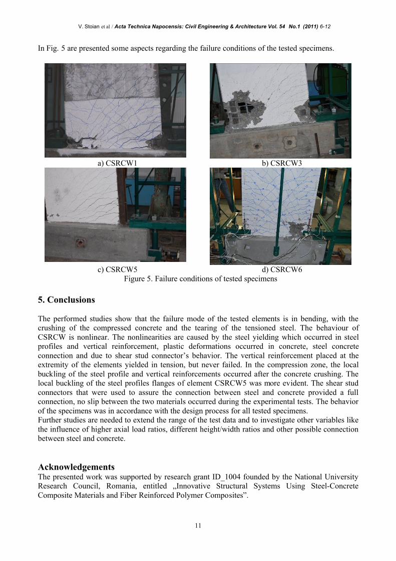
In Fig. 5 are presented some aspects regarding the failure conditions of the tested specimens.
a) CSRCW1 b) CSRCW3
c) CSRCW5 d) CSRCW6
Figure 5. Failure conditions of tested specimens 5. Conclusions The performed studies show that the failure mode of the tested elements is in bending, with the crushing of the compressed concrete and the tearing of the tensioned steel. The behaviour of CSRCW is nonlinear. The nonlinearities are caused by the steel yielding which occurred in steel profiles and vertical reinforcement, plastic deformations occurred in concrete, steel concrete connection and due to shear stud connector’s behavior. The vertical reinforcement placed at the extremity of the elements yielded in tension, but never failed. In the compression zone, the local buckling of the steel profile and vertical reinforcements occurred after the concrete crushing. The local buckling of the steel profiles flanges of element CSRCW5 was more evident. The shear stud connectors that were used to assure the connection between steel and concrete provided a full connection, no slip between the two materials occurred during the experimental tests. The behavior of the specimens was in accordance with the design process for all tested specimens. Further studies are needed to extend the range of the test data and to investigate other variables like the influence of higher axial load ratios, different height/width ratios and other possible connection between steel and concrete. Acknowledgements The presented work was supported by research grant ID_1004 founded by the National University Research Council, Romania, entitled „Innovative Structural Systems Using Steel-Concrete Composite Materials and Fiber Reinforced Polymer Composites”.

V. Stoian et al / Acta Technica Napocensis: Civil Engineering & Architecture Vol. 54 No.1 (2011) 6-12
12
6. References [1] EN 1992-1-1. Eurocode 2: Design of concrete structures, part 1-1, general rules and rules for buildings. [2] EN 1994-1-1. Eurocode 4: Design of composite steel and concrete structures, part 1-1, general rules and
rules for buildings. [3] EN 1998-1. Eurocode 8: Design of structures for earthquake resistance. [4] Dan D., Fabian A., Stoian V., “Theoretical and experimental study on composite steel–concrete shear
walls with vertical steel encased profiles” Journal of Constructional Steel Research, Vol. 67, pp. 800 – 813, 2011.
[5] ECCS - Recommended testing procedure for assessing the behaviour of structural steel elements under
cyclic loads, European Convention for Constructional Steelwork, 1999. [6] Liao F.Y., Han L.H., Tao Z, “Seismic behavior of circular CFST columns and RC shear wall mixed
structures: Experiments”, Journal of Constructional Steel Research, Vol. 65, pp. 1582 – 1596, 2009. [7] Liao, F.Y., Han, L.H., Tao Z. Experimental behaviour of RC shear walls framed with steel reinforced
concrete (SRC) columns under cyclic loading. Steel & Composite Structures 2010, Proc. of the 4-th International Conference.
[8] Guo, L., Ma., X., Zhang, S., Guan, N.: Experimental research on seismic behaviour of two-sided steel-
concrete composite shear walls. Proc. of Eurosteel 2008, Graz, Austria, 3-5 September 2007.