composite materials for bridge · pdf filecomposite materials for bridge construction james...
TRANSCRIPT

COMPOSITE MATERIALS FOR BRIDGE CONSTRUCTION
JAMES E. ROBERTS, P.E., Hon. M. ACI, Hon. M. ASCE Retired Chief Structures Engineer, Director’s Technical Advisor
1960 Tudor Court, Carmichael, CA 95608
ABSTRACT
The California Department of Transportation (Caltrans) has been engaged in cooperative research with various researchers, universities, and material suppliers to stay abreast of the latest developments in engineering materials. The area where Caltrans has pushed the envelope is in the use of advanced composite materials for bridge repair and new construction. We have been working with the University of California at San Diego for the past ten years to develop field applications of advanced composite materials for both repair of older structures and construction of new bridges. These materials are not new but have been used only by the defense and aerospace industries until the mid 1990’s. The most highly developed application to date is the use of advanced composites in repair of bridge columns and other supporting elements to improve their ductility for seismic resistance. Both epoxy impregnated fiberglass and carbon fiber materials have been tested in the laboratory on half-scale models of bridge columns to determine the ductility that can be achieved in an older, non-ductile concrete column. The tests have confirmed the viability of these materials for strengthening existing structures and field application quality specifications have been developed. Since March, 1996 these specifications have been published and included as alternatives in over 50% of the seismic retrofit strengthening contracts advertised for construction in California. The more exciting application of advanced composites is for new bridges and bridge deck replacement units. The research conducted so far has resulted in the design of a highway bridge composed of three foot diameter carbon fiber tubular bridge girders and a fully advanced composite bridge deck. Development of these elements has been underway for six years and field testing of a prototype bridge is currently underway. The bridge design was utilized on a state highway bridge in Southern California which is located on a major truck route for vehicles entering the United States from Mexico. Further development of bridge deck replacement elements composed of advanced composite materials is continuing, with emphasis now on the connection details between older steel and concrete girders and the new composite decks. Although these advanced composite materials are expensive, the long life expected and their resistance to corrosion makes them competitive if the life cycle cost of a bridge in a highly corrosive environment is considered. Future plans in the Caltrans-UC San Diego-Defense Advanced Research Projects Agency (ARPA)-Federal Highway Administration (FHWA) cooperative research program include the construction of a fully composite vehicle bridge on the UCSD campus, which will cross over Interstate 5 north of San Diego. Construction of the smaller bridge is a preliminary step in the development and testing of the various components which will be utilized on this larger bridge.

1. Advanced Composites in Bridge Applications Following the October, 1989 Loma Prieta earthquake Caltrans began a research program, in cooperation with the University of California at San Diego (UCSD), to develop techniques for utilizing epoxy impregnated fiberglass sheets to wrap around older, non-ductile concrete bridge columns as an alternative to the already proven steel jacket technique. The jackets provide sufficient confinement in the concrete to allow them to perform in a ductile manner under seismic loading. It was known that the Japanese had used high strength carbon strands to similarly reinforce industrial stacks and chimneys but the use of glass fiber sheeting had not been used. The major unknown was the durability of the fiberglass materials under cyclic loading and to what level of ductility the columns could be designed. Caltrans technical staff and the principal investigator at UCSD visited the Swiss National Laboratory in Zurich to observe the many durability tests they have performed on composite materials. We also visited several field sites to observe the repair and strengthening applications. The testing program at UCSD was conducted under the same conditions that were used in the testing of steel plate jackets. Half scale models of the prototype bridge columns were constructed, wrapped with the desired layers of glass fiber sheets and tested through several cycles of loading at various levels of ductility until the column failed due to shear failure and consequent degradation of its hysteretic performance. These laboratory tests proved that the epoxy impregnated fiberglass column wraps could develop nearly the same ductile performance as the steel plate jackets. Material properties are readily available from the manufacturers but there remained the issue of adequate quality control specifications for the field application. These early applications were rather crude, being hand laid in a similar manner as hanging wallpaper. It required some months to fully develop adequate quality control (QC) specifications so the materials tested in the laboratory could be replicated with confidence in the field. The application using epoxy impregnated fiberglass has been approved for two systems and field applications have been in place for over ten years. In 1993, following the end of the cold war and reduction of major aerospace and defense applications, the advanced composites industry began looking for applications of advanced composites in the civil infrastructure. The Caltrans-UCSD testing program was expanded to develop similar applications for the higher strength carbon fibers. This testing program has continued as more manufacturers submit their materials for approval and there are at least five systems approved for field application in California at this time. The carbon fibers are applied by automatic wrapping machines which wrap several 1/4 inch strands simultaneously and can fully wrap a typical four to six foot diameter, 20 foot long bridge column in two hours. Because of the higher strength to weight ratio these materials are very competitive with the steel shell retrofit technique, and they can be applied with much less heavy lifting equipment. The materials are much more resistant to corrosion than the steel jackets and they will require very little maintenance. Working in cooperation with the University of California at San Diego research team and the ARPA and FHWA technology transfer programs we have been testing other applications of advanced composites in the seismic reinforcing of older bridges. We have also investigated the construction of major bridge components and ultimately, a complete highway bridge designed for AASHTO loads. The first applications involve resin impregnated fiberglass or carbon sheets on non circular bridge members. These include the use of sheets to wrap and confine the spandrel columns and rib members on several arch bridges where it is difficult to access the

locations with heavy equipment. The second application involves the use of small diameter carbon fiber tubes, constructed by the same technology as rocket bodies, for bridge girders. This application has been tested at the laboratory and design details have been developed for a bridge on the state highway system in southern California. The bridge includes deck units and girders which are composed entirely of advanced composite materials and construction was completed in late Fall of 2000. This bridge, the Storm King Channel Bridge, is on a heavily traveled truck route which handles trucks from Mexico coming into the United States.The testing program for these bridge components has been underway at UC San Diego for over five years, under the ARPA grant.
2. Column Strengthening The most widely used application of advanced composite materials for bridges in California and other states, to date, is the seismic strengthening of bridge columns to improve their ductile performance in an earthquake. However, there is a larger market for this technology in the simple repair and strengthening of columns which have deteriorated from corrosion. It is relatively easy to clean and repair these columns and encase them with the non-corrosive composite materials. This application will undoubtedly increase the life of the columns or piers. Three manufacturers have developed prefabricated resin impregnated-fiberglass shells which can also be used as the form for concrete in the repair process. Many States have followed Caltrans lead and are using these composite shells for both seismic strengthening and non-seismic repair. New York State has been the heavy user to date but other states are following the lead as their confidence in the materials and field applications increases. Figure 1 illustrates the prefabricated fiberglass column shell which has been approved and can be used also for repair of piling below the water line.
Figure 1 Installing Prefabricated Fiberglass Shell
Figure 2a) shows the clamping system utilized to hold the pre-fabricated shell tight until the adhesive cures. This system is the "Clockspring" system, utilizing an Isothalic Polyester resin. Several layers of shells are applied to provide the required ductility. Figure 2b) shows the installation of a full height prefabricated shell. This is the "Du-Pont Hardcore" system, utilizing

a Vinylester resin. These applications were installed in 1996 on the Santa Monica Freeway, Interstate 10, in Los Angeles.
Figure 2a) Clamping the Pre-Fabricated Shell Figure 2b) Full Height Shell A third prefabricated system has been developed by NCF which utilizes several layers of four foot high single shells. The system, known as "Snaptite" is fabricated and heat cured on a mandrel under controlled curing conditions in the manufacturing plant and shipped to the field much the same as the two systems illustrated in figures 1and 2. This system appears much less cumbersome to install than the other two prefabricated systems. Figure 3 shows the use of epoxy-fiberglass as a confinement membrane to increase column ductility and toughness. This was the first application to be tested and approved in California. The material has been used for both circular and rectangular columns. The aspect ratio of the rectangular columns cannot be more than 2:1 or the longer face will buckle under dynamic loading and the needed confinement will not be maintained. This material can be applied as a pre-preg or dry application with the epoxy being applied in the field. One of the initial problems with these materials was uniformity of the final appearance because they are hand laid sheets about three feet wide. Final appearance is dependent on the expertise of the field crew. Attempts have been made to design a machine to improve the application and insure more uniformity, but we have not seen that machine in use in California yet. Careful quality control of the field application and material mixing is necessary to guarantee a quality final product. Figure 4 shows the same material after field application and painting have been completed. The paint serves two functions; one is protection from ultra-violet light and the second is for aesthetics. The concrete colored paint does an excellent job for both functions. This application was implemented in 1991 on the Glendale Freeway (State Route 134) in Los Angeles. These materials had been tested at the UC San Diego Powell Laboratories in 1990 with

excellent results. Both shear and moment ductility of over eight (8) have been achieved in these tests.
Figure 3 Epoxy-Fiberglass Column Wrap Figure 4 Field Application in Laboratory Test Figure 5 illustrates the application of pre-preg carbon fiber wrapping on bridge columns at the field test site. The wrapping machine does not require heavy lifting equipment and a later version now applies more strands simultaneously but can wrap a column of 20 foot height in two hours. The columns are heat cured under controlled conditions by electrically heated blankets or enclosures. The columns are painted concrete color for aesthetic purposes, but the coating does provide protection against the elements. This system has been developed by XXSys Technologies and a second, similar system is being tested by Mitsubishi Industries. The thickness can be varied as the ductility requirements dictate. In the field applications on the Santa Monica Freeway the white paint was also used for the same purposes as on the resin impregnated fiberglass wraps. Figure 6 shows the field application on a seismic retrofit project in San Diego. This material has the potential of becoming the most cost effective column wrapping system because of its high strength to weight ratio. The system does not require heavy lifting equipment and can generally compete favorably against the steel shell retrofit systems. Since it is not as labor intensive as some of the other systems being approved, it will ultimately be the system of choice for most contractors. The controlled heat curing system that is used by XXSys provides a material that is very reliable and has the best chance of guaranteeing the same properties as those of the laboratory samples. This reliability is more difficult to achieve with many of the other systems.

Figure 5 Application of Carbon Fiber Figure 6 Completed Carbon Fiber Wrap ColumnWrap
3. Strengthening Arch Ribs and Spandrel Columns Analysis has shown that the typical arch bridge is extremely vulnerable to seismic forces in the transverse direction and, therefore, it is necessary to retrofit strengthen the main ribs and spandrel columns. Getting any type of erection and application equipment into these locations is very costly and difficult so Caltrans has developed retrofit solutions using carbon or fiberglass sheets. Portions of the arch ribs and the joint where spandrel columns frame into the ribs are being reinforced by wrapping with these sheets. Testing has also been conducted at UC San Diego to evaluate the various sheet systems over the past three years. Results show that the shear capacity increase and confinement can be achieved to the levels required. Full scale tests were conducted during the summer of 1997 on the column-rib joint to determine the material thickness needed to provide the required performance in a seismic event. Use of these materials on older arches is also important from a historical preservation perspective because the sheets do not significantly alter the appearance of the bridges. There are many states who have used these materials to repair and strengthen both circular and rectangular columns.

4. Advanced Composite Bridge The most interesting application of advanced composites to date is the design and construction of an operating bridge on the state highway system. An innovative highway bridge consisting of hollow carbon-composite tubes and lightweight concrete was built on State Highway Route 86 near Palm Springs, California with the construction completed in 2000. The 64 foot long demonstration project was designed cooperatively by Doctor Freider Seible, Professor of Structural Engineering at UC San Diego and California Department of Transportation Bridge Design Engineers. The department will also monitor the bridge for long term performance in comparison with an existing parallel concrete bridge. The project is part of a $9.1 million Defense Advanced Research Projects Agency (DARPA) grant to UCSD and is supported by the Federal Highway Administration through its Technology Applications Office. The design is based on Dr. Seible's easy-to-assemble modular system of hollow tubes, each created of wound carbon fibers and filled with lightweight concrete. The girders and columns will be lightweight concrete filled to facilitate the deck to girder connection details. The deck will be made of a combination of concrete and advanced carbon fiber composites. Figure 7 is a layout and plan of the bridge showing the basic components and dimensions. The bridge will carry normal AASHTO loads and is on a route that carries heavy truck traffic from the agricultural fields in the Coachella Valley and heavy trucks entering the US from Mexico. Figures 8 and 9 show the basic principles of the carbon fiber tubes and concrete in fill. The tubes are manufactured by the same methods that are used in manufacturing rocket body shells for the aerospace industry. Both machine wrapped and hand laid wrapped tubes have been tested at the laboratory at UC San Diego. Figure 10 is a blowup of the deck and component connection details. Figure 11 shows the two major components of the bridge, the girders and deck units. The deck units have been undergoing development and testing at the laboratory for the past four years. The major work that remains is proof-testing the connection details in the field. The laboratory has tested the connections with full sized mockups. Figure 12 illustrates one of the tests for the deck to girder shear transfer performance.
Figure 7 Layout of Storm King Channel Bridge
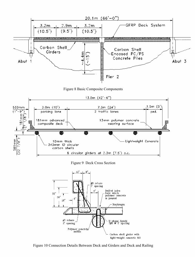
Figure 9 Carbon Tube Details
Figure 8 Basic Composite Components
Figure 9 Deck Cross Section
Figure 10 Cross Section
Figure 10 Connection Details Between Deck and Girders and Deck and Railing

Figure 11 The Major Composite Components
The proposed connection method is to drill holes through the deck units at the dowel locations and fill the space with in-situ polymer concrete. The safety railing for the initial bridge will be made of normal weight concrete but it is not unreasonable to assume that the railing could also be made of advanced composite material shells filled with lightweight concrete. Various types of deck panels produced by several manufacturers have been tested but the final design configuration will probably be determined by economics and constructability as much as by structural requirements. The researchers at UC San Diego have installed four of the deck panels side by side on a campus access road at the laboratory to test their durability under normal traffic, including heavy trucks. The clear span on the test bridge is 15 feet. Figures 13 and 14 are details of the connections at the bents & abutments. The most important need is the development of reliable connection details for the dissimilar materials. This bridge has been heavily instrumented and will provide much valuable information on the actual field performance of these details and of the composite materials. Figure 15 illustrates the light erection equipment installing deck panels. Figure 16 is the completed bridge before the safety railing was poured.

Figure 12 Deck Panel Unit and Girder Connection Test
Figure 13 Bent Cap Beam Connection
Figure 13 Beam Cap/Girder Connection

.
Figure 14 Abutment /Girder Connection
Figure 14 Abutment/Beam Connection .
Figure 15 Light Equipment Placing Deck Panel

Figure 16 Completed Storm King Channel Bridge
It seems obvious that, in the current United States economy, these composite materials are not competitive with the more common bridge materials now being used, unless accurate life cycle costs are considered. It would also seem obvious that the deck panels could solve the problem of deck deterioration in regions of heavy snow and ice where large amounts of salt are used for ice removal. These panels are nearly impregnable, they are not susceptible to corrosion, they are lightweight and do not require heavy lifting equipment like other materials, and they can be mass produced offsite to speed deck replacement. This could potentially be the largest market for advanced composites in bridge construction/ rehabilitation in the US. In time, as usage increases the demand for higher quantities of these materials, the cost will lower and small bridges in remote locations can potentially be one of the most effective applications. The application to a large bridge with 100% advanced composites is still in the future on anything but an experimental basis, but that research and development must be continued to eliminate problems and reduce costs. A novel bridge across Interstate 5 in San Diego is being designed, under the ARPA-FHWA program, to connect two parts of the UC San Diego campus. The bridge is planned as an asymmetrical cable stayed four-lane bridge to carry normal highway loading. Many of the components have been tested and are being utilized in the smaller bridges to gain better performance data under real traffic loading conditions. We know the advantages of these advanced composite materials from the testing and field applications to date. We also know some of the obstacles to be overcome. These programs across the nation and especially the California program are designed to implement the use of these materials into bridge and highway infrastructure as research and good practice permit.

5. Material Testing Program The major concerns associated with the implementation of advanced composite materials into the civil infrastructure are long-term durability and consistency in the field applications. It is imperative that we are able to consistently replicate in the field what we have tested in the laboratory. To insure the necessary quality control Caltrans, in conjunction with the Aerospace Corporation, has developed a comprehensive testing program for the evaluation of advanced composite materials for seismic retrofit and rehabilitation of structures. The Caltrans program was set up to identify the critical parameters and procedures which need to be monitored or controlled to assure the reliable performance of composite retrofitted columns or bridge decks. Cost considerations are an important part of this program. It would be very easy to define tests, inspections, and quality checks that would increase the price of manufacturing composite jackets to the point where they would not be cost competitive with conventional materials. Because of the variations in composites, some testing is unavoidable. However, this program is designed to minimize the testing required to assure a quality product. 5.1 Design Issues and Durability Concerns Caltrans' experience in advanced composites research, trial field demonstrations, as well as through numerous meetings with the industry, revealed a myriad of issues that should be addressed by any public agency. Listed below are issues that must be verified by the engineer of record prior to using composites in infrastructure applications. • Product documentation consistent with application • Process Control • Material Selection Criteria • Material physical properties • Long term durability (chemical and physical) testing of the composite against: •Moisture •Salt attack •Alkali attack •Ozone •High/low temperature extremes •Ultra violet •Other • Quality control in manufacturing, mixing and applying • Fiber content, voids, resin ratio • Design guidelines for the specific composite • Safety factors • Damage and failure modes • Adequate specifications • Repeatability and consistency • Acceptable field erection methods • Effect of fatigue on bond behavior • Performance under dynamic load • Testing under sustained loading • Qualifications of suppliers and product designers

• Cure temperature • Transportation, handling • Maintenance issues Our experience has also revealed crucial issues that are unique to each fiber, resin, and equally important, the manufacturing process and application method. Composites material testing which was conducted by various research institutions show sensitivity to certain environmental factors and possible strength degradation. These results should not necessarily eliminate the use of composites in infrastructure; they merely underscore the need to properly select all components of the composite to suit applications and performance requirements. These results further show the need for safety factors of such magnitude typically not common in conventional construction materials. In addition to column retrofit concepts, some manufacturers have tested upgrading structural members, such as beams and slabs, using carbon fiber. However, only empirical data was generated, with no significant design or durability guidelines. Even though the industry is rich in data related to aerospace and marine applications, the data we need, relevant to civil engineering infrastructure applications, is very limited. 5.2 Program Overview The Caltrans program primarily focuses on two areas of applications: 1 - Seismic retrofit of bridges. 2 - Bridge strengthening and rehabilitation methods. To ensure a sound objective technical evaluation, Caltrans is cooperating with several agencies which possess viable technologies, knowledge and tools to conduct a comprehensive assessment of the various systems under consideration. This cooperative effort is being facilitated by the Society for the Advancement of Material and Process Engineering (SAMPE). Material testing is being performed by the Aerospace Corporation (El Segundo, California). Structural testing is being conducted at the University of California at Irvine (UCI). 5.3 Program Objectives Qualifying well documented composites materials and processes for structural applications is the ultimate goal of the Caltrans effort. In order to achieve such level of confidence, the Caltrans' program is set to accomplish the following objectives: 1 -Identify acceptable material testing methods appropriate for each material type (Carbon fiber, E-Glass, S-Glass, Aramid) and consistent with intended applications. This item includes identifying environmental and physical factors that must be addressed. This objective has been accomplished through the pre-qualification document. 2 -Identify and/or develop structural testing methods to verify shear, confinement and flexural strength of the composite system. The goal is to develop test methods that are capable of demonstrating the structural performance of a given system, yet simple and inexpensive. This objective has been accomplished.

3 -Develop analysis and modeling techniques appropriate for the intended application. Such analysis should take into account the interaction between the composite material and the structure. Work in this area is in progress. 4 -Establish performance criteria for the various materials. 5 -Develop standard specifications and necessary special provisions for viable systems. These specifications should address material types, manufacturing process, mixing and curing, quality control, quality assurance and application methods. Where applicable, ASTM tests will be identified and used. Several projects have been advertised already. Specifications were developed for those contracts. 6 -Develop and adopt design guidelines taking into account environmental and physical factors. Current design guidelines incorporate environmental factor of safety. This factor will be re-examined at the conclusion of the program for any possible need to adjust. 5.4 Material Testing Caltrans issued its pre-qualification requirements in April 1996 and later amended such requirements in January 1997. During the same period, Caltrans issued its Memo to Designers, which states the conditions under which composite alternatives may be used. To help industry participants qualify, Caltrans is carrying out this program for qualifying composite jackets for seismic retrofit of bridge columns. The Aerospace Corporation is supporting Caltrans in the qualification program and is performing environmental durability qualification tests. Degradation of mechanical and physical properties of composite panels is being determined following exposure to various environmental conditions for periods up to 10,000 hours. Environmental exposures include 100% humidity at 100oF immersion in salt water, immersion in alkali solution, ultraviolet light, dry heat at 140oF, a freeze/thaw test, and immersion in diesel fuel. The effects of the environmental exposures are being quantified by measurements of the composite panel mass, tensile modulus, strength, and failure strain, inter-laminar shear strength, and glass transition temperature. Property measurements are being made after exposure intervals of 1,000 hours, 3,000 hours and 10,000 hours to allow estimates of degradation over the projected service life. As of December 1996, property testing following the 1,000 hours and 3,000 hours exposure periods has been completed for three glass fiber/polymer resin systems and for four carbon fiber/polymer resin systems. 5.5 Structural Testing All composite column casing systems are required to satisfy reduced scale cyclic column testing requirements to verify the casing constructability and effectiveness as a seismic retrofit measure. To qualify a system as an alternative column casing for seismic retrofit, a minimum of two types of retrofit enhancements must be demonstrated and tested in accordance with Caltrans requirements. Test results must satisfy Caltrans requirements relative to ductility performance, shear strength, and flexural enhancement. For each shape, cyclic tests must be conducted to demonstrate the performance of both retrofit enhancements and corresponding unretrofitted "As-Builts". Manufacturers may elect to qualify only one shape (circular or rectangular) by satisfying all tests requirements for either the circular tests or rectangular tests, thus limiting their qualifications to these systems.

For each geometrical shape, and for each corresponding enhancement, a minimum of one retrofitted "As-Built" column and one unretrofitted column shall be built and tested. For example, to qualify a system for circular column retrofit applications, the following four test specimens must be constructed and tested: 1. Circular Shear As-Built Column (Unretrofitted) 2. Circular Lap Splice As-Built Column (Unretrofitted) 3. Circular Shear Retrofitted Column subjected to double bending load 4. Circular Lap Splice Retrofitted Column subjected to single bending load. All column details must conform to Caltrans requirements. Retrofit jacket thickness (or fiber ratio) must comply with the current Caltrans design criteria, with proper scaling factors when applicable, and shall satisfy the following: 1. Minimum confinement stress of 300 psi in the lap splice and/or plastic hinging zone 2. Maximum material elongation of 0.001 in/in in the lap splice zone and 0.004 in/in in the plastic hinging zone 3. Minimum confinement stress of 150 psi and material elongation of 0.004 must be maintained elsewhere in the column with appropriate transition 4. Minimum displacement ductility for the retrofitted column of 8 to 12 is to be expected. An expected concrete strength of 5000 psi at the time of testing and Grade 60 reinforcing steel shall be used, although Grade 40 is preferable when available. 5.6 Summary Of Program Tasks The following briefly summarizes tasks which are used to develop the information necessary to qualify vendors to wrap bridge columns with composites for the purpose of seismic retrofitting. All of the data will be cataloged and the program will be managed under one of the tasks. The proposed work includes an analysis of a variety of designs, materials and application techniques to determine the internal stresses in the composite and the strength of the jacket. Two of the tasks involve extensive testing of the composite materials, to fill holes in the database and, using materials from previously wrapped test columns, determine the effect of weathering/aging. Techniques and specifications will be defined under the quality assurance task to guarantee that the vendor's products are consistent and of sufficient quality to fulfill their function. Under the nondestructive evaluation task, techniques will be developed to verify the quality of the jacket as well as the health of the concrete itself. Task 1: Analytical Design Verification - Modeling Objective: Conduct analytical modeling of selected sub-scale tests and estimate a critical flaw size. Help develop a simplified guide for designing composite jackets. Deliverable: Internal stress analysis of selected sub-scale tests and critical flaw size estimation. Task 2: Composite Properties Characterization Objective: Develop specific requirements for manufacturing and testing composite jackets. Identify limits (e.g.. temperature and humidity) allowed during manufacture.

Deliverables: List of recommended test methods. Recommended manufacturing methods and placards. Task 3: Reduced Scale Test Column Verification Objective: Determine the quality of the wraps on the test specimens and the resolution of the nondestructive testing techniques. Deliverables: Nondestructive evaluation maps of selected sub-scale columns both before and after testing . Comparison of test results to analytical models. Task 4: Quality Assurance Objective: Establish the basis for a plan to assure that composite retrofitted columns uniformly meet established performance requirements defined by Caltrans. Deliverables: Define standard test procedures for incoming inspection and witness specimens. Specify/define minimum requirements for quality testing, e.g., number of witness specimens required. Task 5: Non-Destructive Evaluation Objective: Finalize and document column assessment techniques Deliverables: Document the most effective NDE techniques. Demonstrate techniques on sub-scale columns. Task 6: System Evaluation Objective: Develop a manufacturing model to compare total costs of composite jackets with steel jackets. Deliverables: Estimation of labor and material costs for composite jackets and steel jackets Life cycle cost estimates Task 7: Database Organization and Project Management Objective: Collect, assimilate, and store the generated data into a database. Manage tasks 1 through 6. Deliverables: Management, schedule and cost reports Database generated by this and related
programs including: material properties, NDE methods, manufacturing specifications, processes and modal studies. Preliminary results are now available and are published in a report by Sultan of Caltrans and Steckel of Aerospace Corporation. More complete results will be available during the winter of 1997.

6. Field Application Quality Control Specifications Caltrans has developed preliminary construction specifications to ensure quality control for the field applications of advanced composite materials. Separate specifications are available for the various materials but they are generic enough to allow the various vendors of each material to bid, assuming they have passed the qualification tests. Design guidelines are also available for determining the proper thickness of materials.
7. Summary Caltrans has embarked on a program to utilize the advanced composite materials in seismic retrofit strengthening of bridge columns and other structural members. The goal is to increase the shear capacity and develop ductile performance in these members during a seismic event. It seems obvious that, in the current United States economy, these composite materials are not competitive with the more common bridge materials now being used, unless accurate life cycle costs are considered. We know the advantages of these advanced composite materials from the testing and field applications to date. We also know some of the obstacles to be overcome. These programs across the nation and especially the California program are designed to implement the use of these materials into the bridge and highway infrastructure as research and good engineering practice permit.
References 1. California Department of Transportation, Draft Special Provisions-Section 10-1._ Alternative Column Casing, June 1997 2. Priestley, M.J.N., Seible, F., and Calvi, G.M., "Seismic Design and Retrofit of Bridges" John Wiley & Sons, 1996, 686 pp. 3. Seible, F., "Advanced Composites for Bridge Infrastructure Rehabilitation and Renewal" International Conference on Composite Construction, Innsbruck, September 1997 4. Steckel, G.L., and Sultan, M., "Evaluating Advanced Composites For Application In Transportation Structures-A Program Overview" Second FHWA/Caltrans National Seismic Conference, Sacramento, CA, July 1997