composite laminate scarf-repair analysis: software ... laminate scarf-repair analysis: software...
TRANSCRIPT
Composite Laminate Scarf-Repair Analysis: Software Implementationand Experimental Validation
*Sui-An Wang1), Zong-Hong Xie2) and Xiang Li3)
1), 2), 3) School of Astronautics, Northwestern Polytechnical University, Xi’an 710072,China
ABSTRACT
Existing analytical models were modified for the analysis of composite adhesivelyscarf-repaired joints subjected to unidirectional tension. Both analytical models forstepped-scarf repair joints and tapered-scarf repair joints were built, including thestructures without extra plies, with one extra plies. The data structure and algorithmwere developed and Accuracy Degree was defined to assess the accuracy of numericalcalculation, implementing a user-friendly software program for the design and analysisof composite scarf repair under tensile load. The shear stress/strain distribution in theadhesive layer could be presented, the failure level of repair patch and the baselaminate could be evaluated and the ultimate failure load can be predicted.T300/CYCOM-970 was used as adherent and METLBOND 1515-4M was used asadhesive. A series of corresponding experiments were conducted for validation. Theresults calculated by this software showed a good agreement with experimentoutcomes that the relative errors for stepped-scarf repair are less than 5.7% and therelative errors for tapered-scarf repair are not more than 14.0%. This software providesan efficient and accurate preliminary design and analysis tool for the scarf repair ofcomposite laminates.
1. INTRODUCTION
Due to the excellent specific strength, specific stiffness, fatigue properties,corrosion resistance, easy molding, and other outstanding overall performance,advanced composite materials has been widely used in the aviation, aerospace andother fields (Thoppul 2009, Banea 2009), which contributed to the development ofcomposite structure damage assessment technique and repair technique. Compositestructure repair techniques are generally be divided into mechanical connectiontechnique and adhesive bonding technique. Compared with the mechanical connectiontechnique, adhesive bonding technique has numerous advantages and has graduallybeen applied in the maintenance of civil aircraft structures (Wang 2016) .
Analytical approaches for adhesively bonded joints have been proposed by manyresearchers. The earliest study can be traced to Volkersen’s viscous shear model, that
1), 3)Post-graduate student
2)Professor

posited only shear stress existed in the adhesive layer to simplify the solution process(Volkersen 1938). By extending Volkersen’s works, Goland and Reissner consideredthe effect of bending moment at the end of adhesive layer, which not only caused theadherend’s peeling stress, but also affected the distribution of shear stress (Goland1944). Hart-Smith introduced the assumption of elastic-perfectly plastic adhesive,considering the effect of plastic deformation to adhesive film (Smith 1973). Yang andPang applied Classical Laminated Plate Theory to analyze adhesively bonded joints,discussing the anti-symmetric structure and lateral shear deformation’s influence on thejoints (Yang 1993, Yang 1996). Recently, Zhang et al. proposed a method for multi-axial stress analysis of composite bonded joints, taking into account the effect oftransverse shear and heat, and analyzing adherend’s in-plane stress and inter-laminarstress (Zhang 2006). Liu et al. applied a semi-analytical method and FEA into theanalysis of adhesively tapered-scarf joints (Liu 2015).
Ahn et al. adapted Hart-Smith’s model to scarf and double sided lap repair bytaking into account each individual layer separately (Ahn 1998). Based on Ahn’s study,a modified method is presented in this paper, which includes the effect of the number ofextra plies on the mechanical properties of the joints and an improved failure criterionfor assessing adhesive. A repair tool, proposed in the present paper, is aimed to helpdesigners analyze and design the adhesively bonded joints more efficiently.
2. ANALYTICAL MODEL
Composite adhesively bonded scarf repair technique can be generally divided into
tapered-scarf repair joint and stepped-scarf repair joint (Fig. 1). The typical structure
and geometrical properties of a scarf-repaired laminate are illustrated in Fig. 2. Here we
define β as scarf angle, of which tangent is the ratio of the base laminate’s (BL)
thickness H and lap length sd . Additionally, sh is defined as step height. The
smaller sh is, the denser the total steps are, and stepped-scarf structure is closer to
tapered-scarf structure. The correlation between sh and taper-scarf structure is to be
discussed in Section 1.2. The composite adhesively bonded joints can be always
considered as “base laminate-adhesive layer-repair patch”.
Fig. 1 Tapered scarf repair technique (upper) and stepped scarf repair technique(lower)

sd
ed ed
sd H
Fig. 2 Typical structure and geometry of a scarf-repaired joint
2.1 Model of stepped-repaired joint
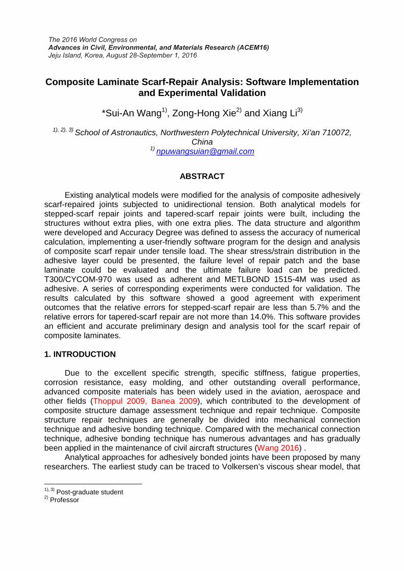
2.1.1 Shear strain expression of adhesiveThe model in the literature (Christensen 1998) only considered shear deformation
along adhesive, without considering peeling stress in adhesive. Both the base laminate(BL) and the repair patch (RP) behaved in linearly elastic manner, while the adhesivelayer exhibited elastic-perfectly plastic behavior (see Fig. 3). The shear strains at theelastic limit and at plastic failure are
efγ andpfγ , respectively. Based on the above
assumptions and simplicity, the expressions for the shear strain in adhesive can beobtained.
In the elastic region, the shear stress expression for i th− segment is
( ) sinh( ) cosh( )i i i i i ie x A x B xγ γ λ λ= = + (1)
where ( )11 11i i L i R
a
Ga a
hλ = +
In the plastic region, the shear stress expression for i th− segment is2
2( )
( )2
iefi i i i
p x x rx sλ γ
γ γ= = + + (2)
Where 11ia is the 11 component of the BL or RP compliance matrix in the i th−
segment; the right superscripts L and R refer to BL and RP; the left superscript i
refers to i th− segment; G is the shear modulus of the adhesive; ah is the thickness
of the adhesive. i A , iB , ir and i s in the Eqs.(1) and (2) are undermined constants
which can be determined from the boundary and continuity conditions.
The shear strain expressions of all segments ( )i xγ (from 1 to K , K is the last
segment) could be obtained under one given tensile load. By Hook’s Law, it is easy to
yield the shear strain expressions ( )i xτ . Then strain and stress in each segment of BL
or RP can be achieved from force balances. Finally, the appropriate failure criteria are
applied to assess the failure degree of the BL, the RP and the adhesive.
Strain
Stress
pτ
efγ pfγ
Fig. 3 The shear stress-strain relation of an elastic-perfect plastic adhesive
2.1.2 Boundary and continuity conditionsAnalysis of the stepped-scarf structure can be simplified to that of a segment
illustrated in Fig. 4. An i th− segment consists of left plastic region, elastic region and
right plastic region, of which the expressions are 1( )ip xγ , ( )i
e xγ and 2 ( )ip xγ
respectively. Fig. 4 also presents the corresponding continuity conditions.1) Boundary condition
The boundary conditions can be expressed as11
11
11
( )( )( 0)
( )( )( )
R
a
K LK
s
a
P adx
dx h
P adx d
dx h
γ
γ
×= − =
× = =
(3)
2) Inter-segment continuity condition
It must be ensured that the shear strain in the adhesive is continuous and the in-plane loads are equal and opposite on the left and right sides of the segment.Accordingly, the continuity conditions at the edge of each segment are
1
1 1111 11
11 11
1 111 11 11 11
11 11
( ) ( )
i i
i L i Ri i
i L i R
i L i R i L i R
i L i Ra
a ad d
dx dx a a
a a a aP
h a a
γ γ
γ γ
+
+ ++
+ +
=
+=
+
−+
+
(4)
3) Elastic-plastic continuity condition
At the locations where the elastic and plastic regions meet ( 1i
px , 2i
px ), the shear
strains in both regions should be equal and continuous

( )
( )( )
i ie p ef
iipe
dd
dx dx
γ γ γ
γγ
= =
=(5)
1i
px2
ipx
i step−
i i i i i ie( x ) Asinh( x ) B cosh( x )γ γ λ λ= = +
2
21 1
2
iefi i i i
p
( )( x ) x r x s
λ γγ γ= = + +
1
1* *( ) ( )
i i
i ii id d
dx dx
γ γ
γ γα β
+
+
=
= +
( )
( )( )
i ie p ef
iipe
dd
dx dx
γ γ γ
γγ
= =
=
2
22 2
2
iefi i i i
p
( )( x ) x r x s
λ γγ γ= = + +
Fig. 4 Equations and continuity conditions for the i th− segment
2.2 Model of tapered-repaired joint
An equivalent method is adopted to obtain the analytical model of the tapered-
scarf structure. When increasing the numbers of total step of the stepped-scarf
structure or reducing the value of sh , the stepped-scarf structure is gradually
approaching the tapered-scarf structure in appearance. The shear strain/stress field is
the key property affects the reliability of the adhesive, thus we observe the change of
the shear strain field to evaluate the rationality of this equivalent method.
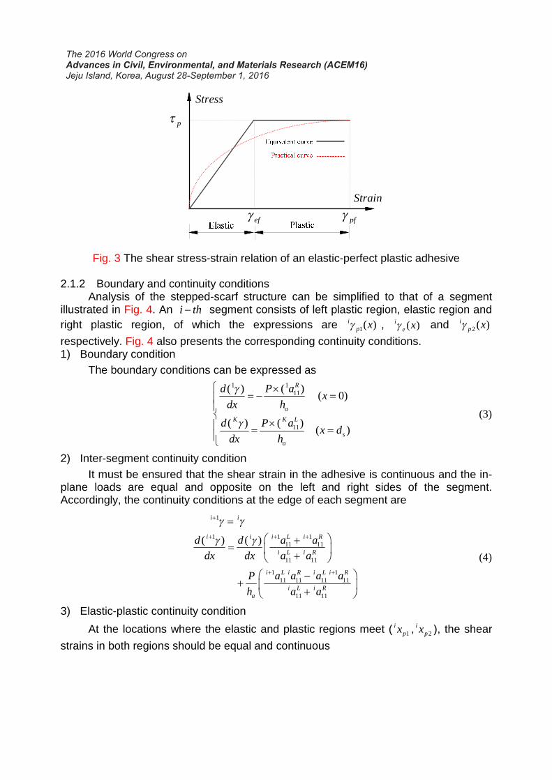
The change of the shear strain and the maximum shear strain of the adhesive is
demonstrated in Fig. 5, when sh varies from 0.125mm (ply thickness of the BL or the
RP) to 0.018mm. As can be seen, with the decrease of sh , the shear strain field tend to
converge into a unique field, and the maximum shear strain approach a specific value
rapidly. The shear strain field is accurate enough once sh is less than 0.03mm.
However, there is no need to set sh to too small value. Exorbitant step numbers may
make the numerical errors φ (see 4.2) soar, resulting in erroneous results. So an
optimum sh should be determined to not only maintain the accuracy of tapered-scarf,
but also guarantee calculating efficiency and numerical errors. Here, the stepped-scarf
model with 0.03sh mm≤ is used as the tapered-scarf model.
0 10 20 30 40 50 600.00
0.05
0.10
0.15
0.20
0.25
0.30
0.35
0.40
Sh
ear
stra
in
Distance aong bondline, x/mm
hs=0.125mmhs=0.042mmhs=0.025mmhs=0.018mm
(a) Shear strain field
0.14 0.12 0.10 0.08 0.06 0.04 0.02 0.000.15
0.20
0.25
0.30
0.35
0.40
She
arst
rain
Thickness per step/mm
Maximum shear strainin the adhesive
(b) Maximum shear strain
Fig. 5 The change of shear strain field/maximum shear strain of the adhesive with sh
changing
3. FAILURE CRITERIA
Adhesively bonded joints may fail in the following modes independently or
combined: (a) BL fracture; (b) RP fracture; (c) Adhesive Delamination. To predict the
strength of the joints, the following failure criteria are introduced.
3.1 Criteria for composite laminate
Among the various failure criteria for composite laminate, Maximum Strain Failure
Criterion is deemed to be one of the best criteria to examine failure. Failure is taken to
occur when in any plies of the BL or RP meets the strain limit. The strain limit refers to
the limited strain at the uniaxial stress state, which is able to be measured by
experiment.
3.2 Criteria for adhesive
Failure of adhesive is generally determined by critical stress criteria or critical
plastic strain criteria, that adhesive fails when the maximum shear stress or strain reach
shear stress limit or shear strain limit.
But actually, damage occurring in a small region cannot lead to absolute failure of
the whole adhesive. According to Damage Zone Theory, adhesive don’t fail until the
damaged area grows to a certain extent (Ban 2008). Here the damaged zone is
modified as the damaged length, of which the shear strain exceeds the plastic shear
strain limit. The range of the limited damaged length is validated by experiment.
For a certain adhesive, the total lap length is sd , the damaged length is pfd .
Then failure indicator is defined as

100%pf
R
s
dD
d= × (6)
When 5%RD > , the adhesive is diagnosed to fail.
4. SOFTWARE IMPLEMENTATION
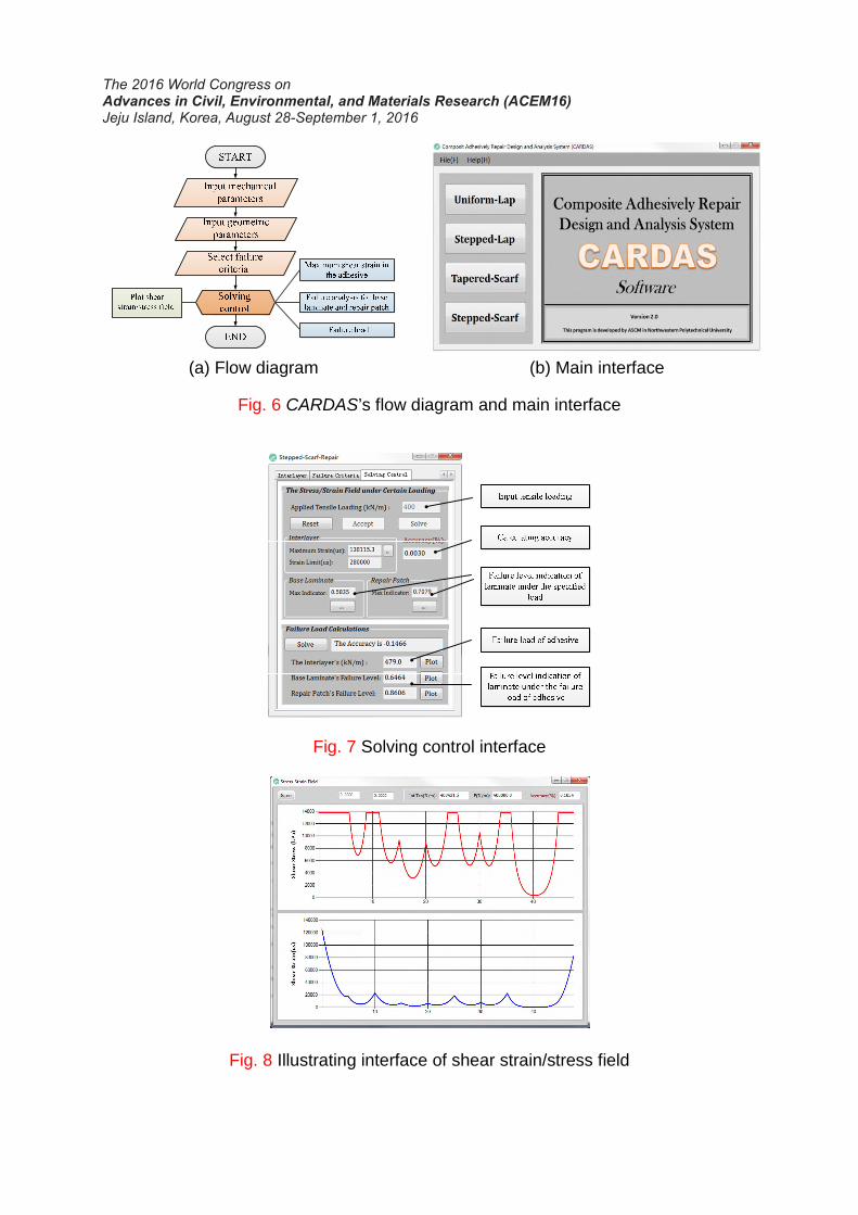
4.1 AlgorithmAccording to the literature (Ahn 1998), there are no more than two elastic-plastic
transition points along the adhesive, which occurs at non-deterministic position. In fact,those points may occur simultaneously at all segments. As is shown in Fig. 8, there area total of eight transition points. Therefore, an independent segment method isproposed, viewing per segment as an independent structure to be analyzed (Fig. 4).
For all the segments, a series of elastic-plastic transition points are defined as 1 2,i ip px x .
The deformation modes of every segment of adhesive can be described by the value of
1i
px and 2i
px . The adhesive of anyone segment generally contains a left plastic zone,
an elastic zone and a right plastic zone (Fig. 4). On the basis of the above solvingstructure, the adhesive could be calculated by the following steps using equations,boundary and continuity conditions summarized in Section 2.
(a) Value of the adhesive shear strain at the first segment 1γ ( 1 0x = ) is assumed under
an applied tensile load P . Combined with the known boundary condition
1
1
0
( )
x
d
dx
γ
=
,the expression of the three zone 11( )p xγ , 1 ( )e xγ and 1
2 ( )p xγ are
obtained; The elastic-plastic transition points 11px and 1
2px are also achieved.
(b) With the expressions of the first segment and inter-segment continuity condition, it
is easy to yield the boundary condition of the next segment, 2
2
0|
xγ
=and
2
2
0
( )
x
d
dx
γ
=
;Then the shear strain expressions of the second segment will be
obtained.(c) Repeat the procedure in step (b) until the last segment K and yield the right
boundary condition
2
2( )
Kk p
Kp
x d x
dR
dx
γ
= −
= ; The difference between R and the actual
value of the boundary condition is defined as 11( )K L
a
P aR
hξ
×= − .
(d) If ξ is less than the desired value, the calculating process ends up with accepting
the initial assumption of 1
1
0|
xγ
=and retaining the shear strain expressions.
Otherwise, turn into step (e).
(e) Chang the assumption of the left boundary condition by 1 1
1 1
0 0| |
x xdγ γ γ
= =+ → and

turn back to step (a). The value of dγ is determined by the change of ξ . If ξ is
getting smaller, it is reasonable to maintain it constant. But if ξ is getting larger, the
sign of dγ is considered to be wrong. So let / 2d dγ γ− → , changing the
direction of the loop. This optimization is so-called “Newton down-hill method”。
The shear strain expressions of the adhesive subjected to a certain load can beachieved through step (a) to (e). The above circulation is called inner-loop. Calculatingthe failure load needs another circulation, serving P as the control variable, which iscalled outer-loop. Newton down-hill method is again used to determine the value of thestep size dP . It will find the desired P where the stress or strain distribution matchesa specific failure criterion through the outer-loop.
4.2 Calculation accuracyDue to the elastic-perfect plastic assumption of adhesive, the models have to be
solved by numerical method indirectly, that will inevitably generate numerical errors. Itmay lead to the erroneous results once the errors are too large. Therefore, it isnecessary to assess the accuracy of the calculation results, determining acceptablecalculating error.
Theoretically, the applied tensile loading should always be equal to the integral ofshear stress along the adhesive. Thus, the calculation accuracy can be described asthe relative deviation of the values of them, namely φ is
*
*
01
100%
( )i
kK d
i
i
P P
P
P x dx
φ
τ=
−= ×
=∑∫(7)
where P is the applied tensile loading; *P is the integral shear stress along the
adhesive ( )i xτ .
When | | 1%φ < , the calculation outcomes are accurate enough to be accepted,
according to experimental validation.
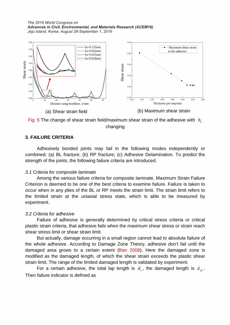
4.3 Software interfaces
Based on the above algorithm, a composite adhesively repair design and analysis
system (CARDAS) was implemented. Fig. 6(a) shows the flow diagram of the software.
The main interface of CARDAS is presented in Fig. 6(b), which contains four types of
adhesively bonded repair techniques, including Stepped-scarf repair technique and
tapered-scarf technique. The interface illustrated in Fig. 7 is the solving control panel,
where user can choose to do the specific calculations and get the relative information.
The shear strain/stress of adhesive could be plotted (see Fig. 8). Compared with FEA,
CARDAS is more adaptable and efficient to do parametric analysis
(a) Flow diagram (b) Main interface
Fig. 6 CARDAS’s flow diagram and main interface
Fig. 7 Solving control interface
Fig. 8 Illustrating interface of shear strain/stress field

5. EXPERIMETN
5.1 Specimen materials
In this study, METLBOND 1515-4M, a stiff adhesive, were used as adhesives.
T300/CYCOM 970, a fiber reinforced weave, were used as adherent. The materials
above were all produced by Cytec. The BL was cured by auto-clave, while the RP was
cured by hot-bonder. The mechanical properties of BL, RP and adhesive were tested in
accordance with the ASTM standards, which are listed in Table 1 and 2.
Table 1 Mechanical properties of the laminates and the adhesive film
Mechanical propertiesT300/CYCOM970(Autoclave)
T300/CYCOM970(Hot-bonder)
Metlbond1515-4M
1( )E GPa 66.5 59.1 3.57
2 ( )E GPa 66.5 59.1
12 ( )G GPa 4.7 3.9 0.37
12ν 0.07 0.05
( )tX MPa 611.1 510.6
( )tY MPa 611.1 510.6
( )S MPa 121.3 113
( )p MPaτ 13.8
pfγ 0.30
Table 2 Geometrical properties of the materials
Geometrical propertiesBase
laminate
Repair
patchExtra plies Adhesive
Ply sequences (0/45)2S (0/45)2S (0)2
Ply numbers 8 8 1~2
Ply thickness(mm) 0.210 0.210 0.205 0.125
5.2 Specimens and testsDouble-sided lap repair specimen: The lap length pL of the four sets of
specimens is 5mm, 15mm, 25mm and 35mm respectively. The width of all specimensis 25mm, of which other geometric parameters are shown in Fig. 9. The properties pτ
and pfγ of the adhesive were hardly measured, therefore, double sided lap repair
tests were implemented to deduce those two properties. The method is matching the

model to the four data points, to get optimum value of pτ and pfγ .
pL
Fig. 9 Geometric parameters of adhesively double stepped-lap joints
Stepped-scarf repair specimens: The equivalent scarf angle is 3o and the total
lap length is 40mm. The numbers of step are 2, 4, 8 (corresponding step lap length are
40mm, 13.4mm and 5.7mm) respectively. For 4-steps specimens, specimens with one
extra ply and with two extra plies were added, of which per extra lap length is 12.5mm
(Fig. 10).
Fig. 10 Geometric parameters of adhesively stepped-scarf joints
Tapered-scarf repair specimens: In terms of numbers of extra plies, the
specimens can be divided into specimens with one extra ply and specimens with two
extra plies. The design scarf angle was 2o ,3o , 4o , 5o (actual scarf angles are listed in
Table 4) respectively. Other geometrical parameters were shown in Fig. 11.
Fig. 11 Geometric parameters of adhesively tapered-scarf joints
An HUALONG DW-300 hydraulic pressure servo material testing machine was
used for the tensile tests (Fig. 12). The load was applied at a constant head

displacement rate of 1mm/min up to ultimate failure of the specimens.
Fig. 12 Tensile testing setup of scarf-repaired specimen
6. EXPERIMETNTAL RESULTS AND DISCUSSION
6.1 Experimental results
Tensile test results of stepped-scarf repaired joints are listed in Table 3. Those
measured data are stable and reliable, of which the coefficients of variation (CV) are
pretty small (mostly below 5%). The strength recovery ratio of specimen without extra
plies is 27.2%, 40.6% and 48.9% (specimen’s strength/BL’s strength) respectively.
Every doubling the number of the steps can increase a 10.9% extra strength recovery
on average. For specimens with 4 steps, the strength recovery ratio varies from 40.6%,
44.8% to 48.3%. One additional extra ply adds to an average 3.9% extra strength
recovery. Increasing the number of step or extra ply can effectively reduce the edge
stress concentration and improve stress distribution, to markedly enhance the strength
of the joints.
Table 4 presents the tensile test results of tapered-scarf repaired joints, of which
the CV is slightly larger than that of stepped-scarf joints’ results. But the test data of
tapered-scarf is still stable and reliable enough. The strength recovery ratio of the
specimens ranges from 34.9% to 67.6%. The strength of tapered-scarf repair joints is
negatively related to scarf angle in the range from 1.5 degree from 5 degree. Adding
the number of extra ply has an obvious strength promotion to the joints. Under the
same scarf angle, the joints with two extra plies obtain an average strength promotion
of 44.7MPa (7.3%) than the joints with one extra ply.
Clamps
Extensometer

Table 3 Tensile test results of stepped-scarf repaired joints
SpecimenNumber of
specimens
Number
of steps
Number of
extra plies
Strength (MPa)
Average CV(%)
A1 3 2 0 166 0.6A2 3 4 0 248 1.7A3 3 4 1 274 3.8A4 3 4 2 295 8.8A5 3 8 0 299 1.6
Table 4 Tensile test results of tapered-scarf repaired joints
SpecimenNumber of
specimens
Scarf angle Number of
extra plies
Strength(MPa)
Design Actual Average CV(%)
B1 32 1.75
1 406 4.3B2 3 2 413 2.9C1 3
3 2.631 342 5.6
C2 3 2 353 7.5D1 3
4 3.501 263 7.5
D2 3 2 335 11.1E1 3
5 4.381 213 8.1
E2 3 2 302 16.4
6.1 Discussion
The mechanical and geometrical parameters of those specimens and selected
failure criteria were input into CARDAS to gain the corresponding calculation strength
of the specimens. Stepped-scarf’s comparison of experimental strength and calculation
strength for the joints without extra ply is shown in Fig. 13(a). The calculation results
are consistent with the experimental results (maximum relative error below 5.7%).
Comparison for the joints with 4 steps is shown in Fig. 13(b). Those calculation results
also show a good agreement with the experimental results. The relative errors are all
less than 4.3%. As seen, the proposed software yields good prediction for all the
stepped-scarf repair joints.
Fig. 14 shows the curves relating calculation strength to scarf angle for joints with
one extra ply and with two extra plies, respectively. The experimental results are
scattered on the corresponding figures for comparison. Those two calculated curves
reflect the decreasing trend of joints’ strength with scarf angle increasing. As seen, the
experimental results are perfectly in accordance with the calculated curve for the joints
with one extra ply (Fig. 14(a)). The relative errors at the four test points are all less than
4.5%, which are pretty small. By contrast, in Fig. 14(b) the experimental results for the
joints with two extra plies don’t agree so well with the corresponding calculated results

(maximum relative error 14.0%). The joints with two extra plies can achieve an
increased calculation strength of 41.4MPa than the joints with one extra ply on average.
The value is quite consistent with the experimental results (44.7MPa).
2 steps 4 steps 8 steps0
100
200
300
400
Str
engt
h/(
MP
a)
Eperimental dataCalculation result
(a) With no extra plies
No extra plies 1 extra ply 2 extra plies0
100
200
300
400
Str
engt
h/(
MP
a)
Eperimental dataCalculation result
(b) 4 steps
Fig. 13 Stepped-scarf’s comparison of experimental strength and calculation strength
1.5 2.0 2.5 3.0 3.5 4.0 4.5 5.0100
200
300
400
500
Str
engt
h/(M
Pa)
Scarf angle (Degree)
Calculation result(1 extra ply)Experimental data(1 extra ply)
1.5 2.0 2.5 3.0 3.5 4.0 4.5 5.0100
200
300
400
500
Str
engt
h/(M
Pa)
Scarf angle (Degree)
Calculation result(2 extra plies)Experimental data(2 extra plies)
(a) With one extra ply (b) With two extra plies
Fig. 14 Tapered-scarf’s comparison of experimental strength and calculation strength
7. CONCLUSIONS
In this study, the mechanical behaviors of four different types of stepped-scarf
joints and eight different types of tapered-scarf joints subjected to tensile loading were
investigated by analytical calculation and experimental validation. Accordingly, the

following conclusions can be drawn:• Analytical model for stepped-scarf repair and tapered-scarf repair are presented.
The corresponding data structure and algorithm for the analytical models are
developed to implement the software CARDAS, which is helpful to do parametric
analysis to adhesively bonded joints efficiently.
• According to the data obtained from the experiments, for the stepped-scarf joints
having the same lap length, every doubling the number of the steps can increase a
10.9% extra strength recovery on average and one additional extra ply adds to an
average 3.9% extra strength recovery.
• For the tapered-scarf joints having the same extra ply, the strength is negatively
related to scarf angle in the range from 1.5 degree from 5 degree. The joints having
the same scarf angle with two extra plies obtain an average strength promotion of
44.7MPa (7.3%) than that with one extra ply.
• Comparisons between experimental results and calculation results show a good
agreement. For stepped-scarf joints, the maximum relative error is just 5.7%, while
it is 14.0% for tapered-scarf joints. Accordingly, the proposed software CARDAS is
a practical assistance tool for analysis and design of composite laminate adhesively
bonded repair.
ACKNOWKEDGMENTS
The work is supported by the National Natural Science Foundation of China
(Grant No. U1233202)
REFERENCES
Ahn S H, Springer G S. (1998), “Repair of Composite Laminates-II: Models.” Journal ofComposite Materials, Vol. 32(11):1076-1114.
Ahn S H, Springer G S. (1998), “Repair of composite laminates-I: test results.” Journalof Composite Materials, Vol. 32(11):1036-1074.
Ban C S, Lee Y H, Choi J H, et al. (2008), “Strength prediction of adhesive joints usingthe modified damage zone theory.” Composite Structures, Vol. 86(1–3):96-100.
Banea M D, da Silva L F M. (2009), “Adhesively bonded joints in composite materials:an overview.” Proceedings of the Institution of Mechanical Engineers, Part L: Journalof Materials Design and Applications, Vol. 223(1): 1-18.
Bednarcyk B A, Zhang J, Collier C S, et al. (2006), “Analysis tools for adhesivelybonded composite joints, part 1: higher-order theory.” AIAA journal, Vol. 44(1): 171-180.
Christensen, R. M, McCoy, J. J. (1970), Mechanics of Composite Materials, PergamonPress.

Thoppul S D, Finegan J, Gibson R F. Mechanics of mechanically fastened joints inpolymer–matrix composite structures–a review[J]. Composites Science andTechnology, 2009, 69(3): 301-329.
WANG Yishou, QING Xinlin. Progress on study of structural health monitoringtechnology for composite joints. AMCS, 2016, 33(1): 1-16.
Goland M, Reissner E. (1944), “The stresses in cemented joints.” Journal of appliedmechanics, Vol. 11(1): A17-A27.
Hart-Smith L J. (1973), Adhesive-bonded single-lap joints, Hampton, VA: LangleyResearch Center.
Liu B, Xu F, Ji Z, et al. (2015), “Modified semi-analytical method for adhesive stress ofscarf joints in composite structure.” Acta Materiae Composite Sinica, Vol. 32(2):526-533
Volkersen O. (1938), “Rivet strength distribution in tensile-stressed rivet joints withconstant cross-section.” Luftfahrforschung, Vol. 15(1): 41-47.
Yang C, Pang S S. (1993), “Stress-strain analysis of adhesive-bonded single-lapcomposite joints under cylindrical bending.” Composites Engineering, Vol.3(11):1051-1063.
Yang C, Pang S S. (1996), “Stress-strain analysis of single-lap composite joints undertension.” Journal of Engineering Materials and Technology, Vol. 118(2): 247-255.
Zhang J, Bednarcyk B A, Collier C S, et al. (2006), “Analysis tools for adhesivelybonded composite joints, part 2: unified analytical theory.” AIAA journal, Vol. 44(8):1709-1719.