composicad™ cpv for tanks & pressure vessels (silver package) · composicad™ cpv for tanks...
TRANSCRIPT
ComposicaD™ CPV for Tanks & Pressure Vessels (Silver Package)
What makes ComposicaD the best software for producing pressure vessels? Let’s take a look…
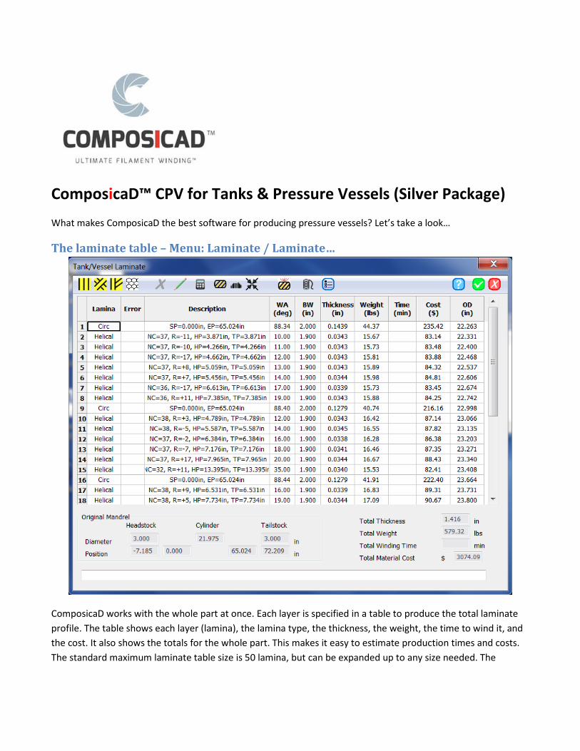
The laminate table – Menu: Laminate / Laminate…
ComposicaD works with the whole part at once. Each layer is specified in a table to produce the total laminate profile. The table shows each layer (lamina), the lamina type, the thickness, the weight, the time to wind it, and the cost. It also shows the totals for the whole part. This makes it easy to estimate production times and costs. The standard maximum laminate table size is 50 lamina, but can be expanded up to any size needed. The

laminate table can be copied and pasted into other software (such as a spreadsheet or word processor) for documentation purposes.
This sequence of laminas, along with the material and liner properties (more on these later), completely defines the composite material for your pressure vessel. This table is easy to build by inserting the desired lamina type. You can also copy sections and cut and paste the sections to quickly build the desired lamina sequence.
Each entry in the laminate table can be one of four types – a helical winding, a circumferential (circ or hoop) winding, a connector (or transition) winding or another type (liner, metal fittings, cores, fabrics, etc.). Each type of lamina has a set of parameters that specify the winding path or other material properties.
Helical Winding - button The Helical Dialog shows the parameters that are used to specify the exact nature of the helical winding path. The major parameters for a helical winding on a pressure vessel are the two pole opening diameters and the winding angle.
If the vessel (or this layer) is symmetric then, the Symmetric check box makes both ends of the vessel the same. If not symmetric, then each end can be specified individually. ComposicaD calculates the natural or geodesic winding angle given each pole opening size and the diameter of the main cylinder. If the two pole sizes are unequal, then it calculates a geometric mean of the two angles, which would produce the least amount of needed friction.
If the Use Geodesic angle check box is checked, then ComposicaD uses the mean angle as the winding angle in the cylindrical section. If not, you can specify the desired winding angle in the cylinder and ComposicaD will calculate the required slip potential and highlight if it is over the
maximum slip potential that was specified for the material being used.
If you specify a winding angle, then ComposicaD calculates the pole opening size for a geodesic path. If you check the Use Geodesic Diameter check box, ComposicaD will use this diameter for the pole diameter. This diameter requires the least amount of friction.

The user has complete control over the number of circuits used for coverage. ComposicaD calculates the minimum number of circuits required for complete coverage (at least 100%). If the Use calculated circuits check box is checked, then this number of circuits is used. If not, you can enter the desired number of circuits.
A number of layers can also be specified. Normally this is only used for a few layers, because the thickness buildup of each layer alters the mandrel shape and a new winding pattern should be used as the thickness increases.
ComposicaD calculates the possible pattern repeats and then if the Use closest pattern repeat check box is checked it uses the closest repeat based on a set of rules that are specified by the user.
ComposicaD defaults to the most common approach used for helical winding. The rules dialog can also be used to specify how each layer in the
laminate will change the pole opening size.
The Repeat menu also shows pertinent information about the winding pattern, such as, the deviation from the natural path, the adjusted winding angle, and the adjusted percent coverage. Additional dwell can also be added to the headstock or tailstock pole, if desired.
Pattern repeat is the way a helical pattern closes on a part. A single circuit pattern (repeat of +1 or -1) lays each fiber beside the previous fiber. A three circuit pattern (repeat of +3 or -3) would lay the fourth fiber band beside the first and so on.
The repeat produces a “Star” of the number of points in the repeat on each end of the mandrel around the pole. It also changes the look of the winding in the cylinder section. Some people like the look of low repeat numbers
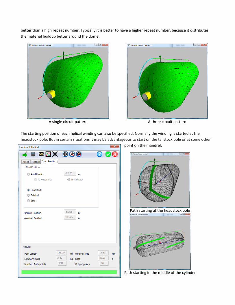
better than a high repeat number. Typically it is better to have a higher repeat number, because it distributes the material buildup better around the dome.
A single circuit pattern
A three circuit pattern
The starting position of each helical winding can also be specified. Normally the winding is started at the headstock pole. But in certain situations it may be advantageous to start on the tailstock pole or at some other
point on the mandrel.
Path starting at the headstock pole
Path starting in the middle of the cylinder
It is useful to change the starting positions to minimize the length of the connector paths. This is done for highly optimized windings.
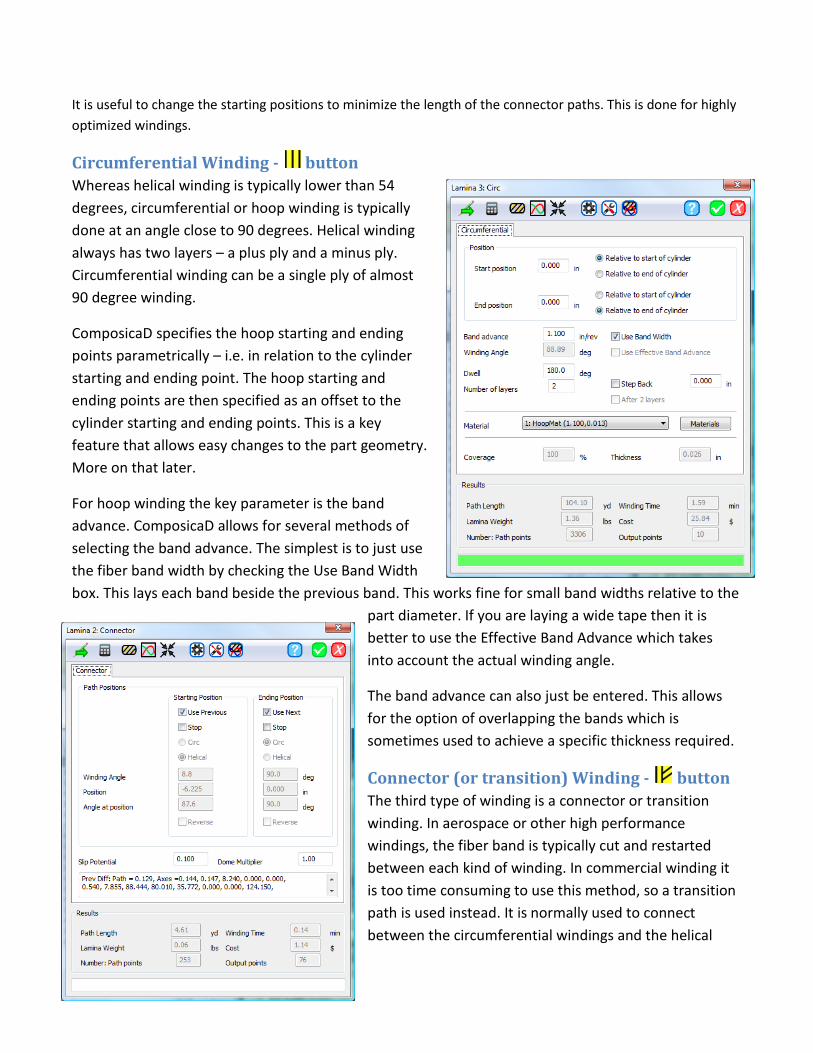
Circumferential Winding - button Whereas helical winding is typically lower than 54 degrees, circumferential or hoop winding is typically done at an angle close to 90 degrees. Helical winding always has two layers – a plus ply and a minus ply. Circumferential winding can be a single ply of almost 90 degree winding.
ComposicaD specifies the hoop starting and ending points parametrically – i.e. in relation to the cylinder starting and ending point. The hoop starting and ending points are then specified as an offset to the cylinder starting and ending points. This is a key feature that allows easy changes to the part geometry. More on that later.
For hoop winding the key parameter is the band advance. ComposicaD allows for several methods of selecting the band advance. The simplest is to just use the fiber band width by checking the Use Band Width box. This lays each band beside the previous band. This works fine for small band widths relative to the
part diameter. If you are laying a wide tape then it is better to use the Effective Band Advance which takes into account the actual winding angle.
The band advance can also just be entered. This allows for the option of overlapping the bands which is sometimes used to achieve a specific thickness required.
Connector (or transition) Winding - button The third type of winding is a connector or transition winding. In aerospace or other high performance windings, the fiber band is typically cut and restarted between each kind of winding. In commercial winding it is too time consuming to use this method, so a transition path is used instead. It is normally used to connect between the circumferential windings and the helical

windings and vice versa. This path gradually uses the allowed slip potential to deviate the path from the geodesic to move from one winding angle to the next.
The parameters are the allowed slip potential and a slip potential multiplier used in the dome regions. Sometimes it is nice to use more or less friction in the domes, so you can specify a multiplier to increase or decrease the pattern change in the domes.
A diagram showing a helical winding (blue – only one circuit shown), the connector winding (yellow) and a circumferential winding (red – band advanced exaggerated for clarity).
Materials - button ComposicaD uses a material database. Up to 10 materials can be specified in the standard version. Each of the winding patterns uses a material in the database. If you need to change a material for some reason, then it is easy to recalculate all of the windings (laminas) based on the new material. Each material has a
bandwidth, band thickness fiber properties, resin properties, and fiber / resin fraction either by weight or volume. Also the maximum slip potential allowed for the material is specified. Additional parameters can be specified in the Parameters tab, such as Young’s Modulus, Poison’s ratio and other material properties which are used by other functions in ComposicaD such as the FEA option. Materials can be Rovings, Prepregs, Tape or Other

Material. Each type of material has parameters that are common for that type of material so it is easy to specify.
The liner (mandrel) geometry - Menu: Part / Tank or Vessel… A typical pressure vessel consists of two domes connected by a cylindrical section (cylinder). The geometry of
the domes is typically chosen based on several factors. Two common types of dome geometries are an “isotensoid” or an elliptical (or almost elliptical) shape. ComposicaD supports both types of dome geometries. An opening in the dome or a pole is typical.
Many vessels are symmetric, but some are not, with different dome geomtries and pole openings. ComposicaD makes it easy to select either symmetric or non-symmetric shapes.
In addition a shaft can be specified on either or both ends. This shaft does not enter into the winding calculations but is used to verify part clearances in the Simulation option and to provide for a realistic display.
The number of seqments in the domes, the cylindrical section and radially around the part are specified too. Using more segments typically provides a more accurate path generation at the cost of bigger files and longer computation times.
Mandrel geometries can also be entered via a mandrel file, which also for the exact dome shapes to be specified for the FEA analysis. A new feature in ComposicaD is the Design Tab, which allows the designer to make a preliminary design of the vessel using netting analysis. More on this later in the paper.
Handling the thickness buildup - Output Options button Each layer that we put onto the mandrel (liner) increases the diameter of the mandrel and changes its shape. Typically the thickness of each lamina is different in different places. This is especially true of the helical windings. Typical thickness variation in a helical winding can be as high as 6 to 1. The thickness is significantly higher in the turnaround region near the pole openings. It is caused by two effects: the decrease in the winding diameter and the increase in the winding angle; both tending to increase the thickness near the poles. Because of actual physical effects, primarily slipping of the roving band when winding, it is

very difficult to model this thickness change. ComposicaD uses an empirical model to accurately model this thickness buildup.
Normally in ComposicaD we just add the calculated thickness for each layer to the previous mandrel shape to get the new mandrel shape. For special applications we can also specify no change to the mandrel shape, add a constant thickness radially and axially or load a new mandrel shape from a file.
This ability to accurately model the thickness buildup is one of the key features of ComposicaD. it allows for the very simple creation of very thick laminates.
The diagram on the left shows the thickness build up of the part shown in the laminate table above. Notice the increased thickness around the poles due to the large helical lamina thickness at the poles. This thickness buildup is the reason that many pressure vessels step the helical windings back from the pole for each layer put on the part. This tends to keep the thickness more uniform in the dome area. Also notice the increased thickness in the cylindrical section due to the circumferential windings.
Composicad has several options for the Next Mandrel generation that can be used to optimize winding or FEA Analysis.
Delivery Envelope When winding, we do not normally want to contact the mandrels surface. ComposicaD allows us to specify an offset from the mandrel surface, both axially and radially, which will specify an envelope (contour) that the delivery eye will follow. Normally ComposicaD uses a smooth envelope shape that is specified by the Elliptical Radio button and an elliptical radius. This radius is used to smooth the corners of the delivery envelope. The axial and radial offsets and a minimum radial position can be

specified. A delivery envelop can also be imported from a file or generated from the mandrel shape.
This diagram shows the mandrel and an elliptical delivery envelope. The color of the envelope signifies if it has been shifted one way or the other (blue for shift to headstock; yellow for shift to tailstock) and if
the closest approach has been limited (red). Different minimum radial positions can be specified for the headstock and tailstock allowing for non-symmetrical mandrels or for mandrels that are cantilever mounted in the winding machine.
The shape of this delivery envelope can significantly increase winding speeds for low angle helical winding, because of the rounded contours.
Controlling the Motion Output The Motion tab of the Output Options dialog lets us control how the machine output is being generated. We have several options for a time base, but normally in filament winding we like to run as fast as we can to minimize production time. This is accomplished in ComposicaD by use of a special algorithm called “Time optimal fixed trajectory path generation”. Essentially the algorithm moves all of the axes at the fastest rate it can, without exceeding the maximum velocity or acceleration on any axis.
One of the great features of ComposicaD is that it also includes the fiber payout rate as one of the controlled axes. This is especially important for wet winding, when the maximum payout rate should not be exceeded to produce good fiber band wet out.
ComposicaD also has an extensive set of output filters which can be used to minimize the number of output

points generated and other options that optimize the output for the specific machine controller.
Smoothing Accelerations and velocities can be controlled on an individual axis basis. The acceleration and velocities are specified as a percentage of the maximum machine acceleration.
Before / After Commands ComposicaD allows the programmer to include other commands before or after a lamina. Commands that affect the winding, such as Tension control, Mandrel pressure, Resin Bath temperature or other process paramaters, can be included if the machine controller supports these commands.

Path Display Options - button & Display button ComposicaD has numerous options for display of the winding paths. Mandrel options, band options, colors,
delivery envelope, coordinate axes, and a path color display for thickness and winding angle are all options.
The figure above shows the winding pattern with the color display set to show the winding thickness. The red color indicates the much thicker section around the poles.
The figure on the left shows a complete laminate. The colors denote which laminate layer. You can see the progression of helical windings, each moving out slightly from the pole opening (blue, green, yellow, light orange). You can also see one of the transition windings (orange) and the final circumferential layer (red)

Graph Display Options - button & Graph - button ComposicaD has an extensive set of options to display the machine outputs – positions, velocities and accelerations.
Axis information can be plotted against time, spindle position, carriage position or for each point. Scale can be set as a percentage of machine range or of pattern range or to absolute position.
The figure on the right shows the axis positions plotted against the carriage position. It displays the typical shape for the rotating eye motion and also shows the envelope shape for the radial carriage.

Parametric Calculations – A huge time saver Many pressure vessels are members of a family – a certain diameter of tank has several different models in different lengths. In ComposicaD it is extraordinarily easy to make these families of vessels. Here is an example:
18 inch diameter
12 inch cylinder section
24 inch long cylinder section
36 inch long cylinder section

The laminate table is the same for each of these vessels. The only thing that is changed is the cylinder length in the Part menu:
When the menu is exited then ComposicaD asks if you want to recalculate. Click, “Yes”
and all of the winding paths are recalculated based on the new liner length. This feature can save many hours of programming time necessary with other filament winding software.
The part diameter can also be changed. This works best when the pole opening size stays the same.
Support for multiple machines of any type – Menu: Machine / Select & Menu: Machine / Controller
Just select the desired machine from the list. ComposicaD comes standard with one machine / controller type, but can be easily upgraded to up to eight machines.

Supported controllers include all of the commercial winding machine manufacturers. Any kind of CNC controlled winding machine can be supported.
Composite Pressure Vessel Design ComposicaD CPV now includes a very useful preliminary design feature that allows us to calculate a
first approximation of the required laminate thickness for a specified burst pressure using netting analysis. Using the Design Tab we can specify a desired operating pressure and the safety factor to get the desired burst pressure. Typical safety factors can be specified or a custom factor used. Pressures are given in MPa, bar and psi.
The Winding Angle can be specified or the geodesic angle from the mandrel geometry can be used. Material properties - the fiber volume fraction, Ultimate Fiber Stress and Elongation [strain] - from the material data base are utilized or can be entered. ComposicaD then calculates the required thickness of Helical and Circumferential layers using the well-known Netting Analysis theory. The required number of layers is also calculated.
Mandrel dimensions and liner properties are calculated or entered to get approximate vessel volume and size at room and
operating pressure.
This tool combined with the Laminate Burst tool (on the Laminate Table) gives a good first approximation of the actual vessel burst pressures (assuming the domes and laminate are designed correctly). The laminate Burst tool uses the actual laminate structure to calculate the burst pressure based on the Netting Analysis method. Burst pressure is given as an actual pressure and as a percentage of the design pressure.

Other Analysis Options –Export to FEA… / Export to ESAComp… / Export to WCM…
ComposicaD has several other Analysis capabilities. Included in the base ComposicaD package are Export to ESAComp. The ComposicaD FEA Output option gives ComposicaD the capability to produce data for use by other commercial FEA programs and Export to WCM (the Abaqus Wound Composite Module). ComposicaD can produce data formats compatible with ABAQUS, ANSYS, NISA, and other FEA packages. Both shell and 3D elements can be supported.
Above, a display showing the 3D Elements for import into Abaqus (or other 3D model).

The display on the left is from ESAComp a low cost tool for composite design from Componeering, Ltd.

See more on the web at: www.ComposicaD.com
ComposicaD™ is available exclusively through Seifert and Skinner & Associates and leading winding machinery manufacturers