components in products
TRANSCRIPT
1/4/2015
1
The image cannot be displayed. Your computer may not have enough memory to open the image, or the image may have been corrupted. Restart your computer, and then open the file again. If the red x still appears, you may have to delete the image and then insert it again.
Chapter 8
Screws, Fasteners, and the Design of
Nonpermanent Joints
Lecture Slides
The McGraw-Hill Companies © 2012
COMPONENTS IN PRODUCTS
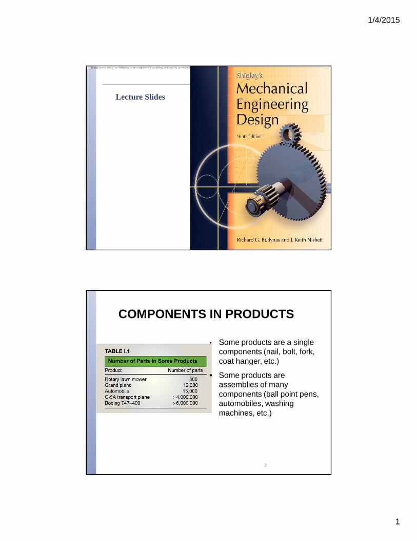
• Some products are a single components (nail, bolt, fork, coat hanger, etc.)
• Some products are assemblies of many components (ball point pens, automobiles, washing machines, etc.)
2
1/4/2015
2
IntroductionIntroduction
The fundamental operation in manufacture is the creation of shape - this
includes assembly, where a number of components are fastened or joined
together either permanently by welding for example or detachably
(nonpermanent) by screws, nuts and bolts and so on.
Since there is such a variety of shapes in engineering to be assembled, it
is hardly surprising that there is more variety in demountable fasteners
than in any other machine element.
Fasteners based upon screw threads are the most common, so it is
important that their performance is understood, and the limitations of the
fastened assemblies appreciated. 3
Reasons for Non-permanent Fasteners
Field assembly Disassembly Maintenance Adjustment
1/4/2015
3
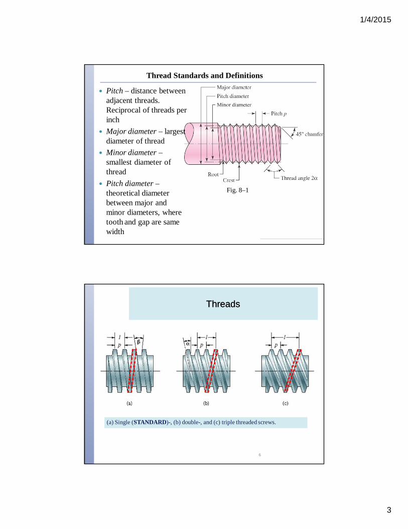
Thread Standards and Definitions
Pitch – distance between adjacent threads. Reciprocal of threads per inch
Major diameter – largest diameter of thread
Minor diameter –smallest diameter of thread
Pitch diameter –theoretical diameter between major and minor diameters, where tooth and gap are same width
Fig. 8–1
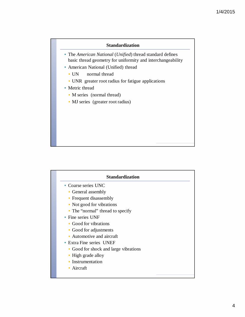
ThreadsThreads
(a) Single (STANDARD)-, (b) double-, and (c) triple threaded screws.
6
1/4/2015
4
Standardization
• The American National (Unified) thread standard defines basic thread geometry for uniformity and interchangeability
• American National (Unified) thread• UN normal thread• UNR greater root radius for fatigue applications
• Metric thread• M series (normal thread)• MJ series (greater root radius)
Standardization
• Coarse series UNC• General assembly• Frequent disassembly• Not good for vibrations• The “normal” thread to specify
• Fine series UNF• Good for vibrations• Good for adjustments• Automotive and aircraft
• Extra Fine series UNEF• Good for shock and large vibrations• High grade alloy• Instrumentation• Aircraft
1/4/2015
5
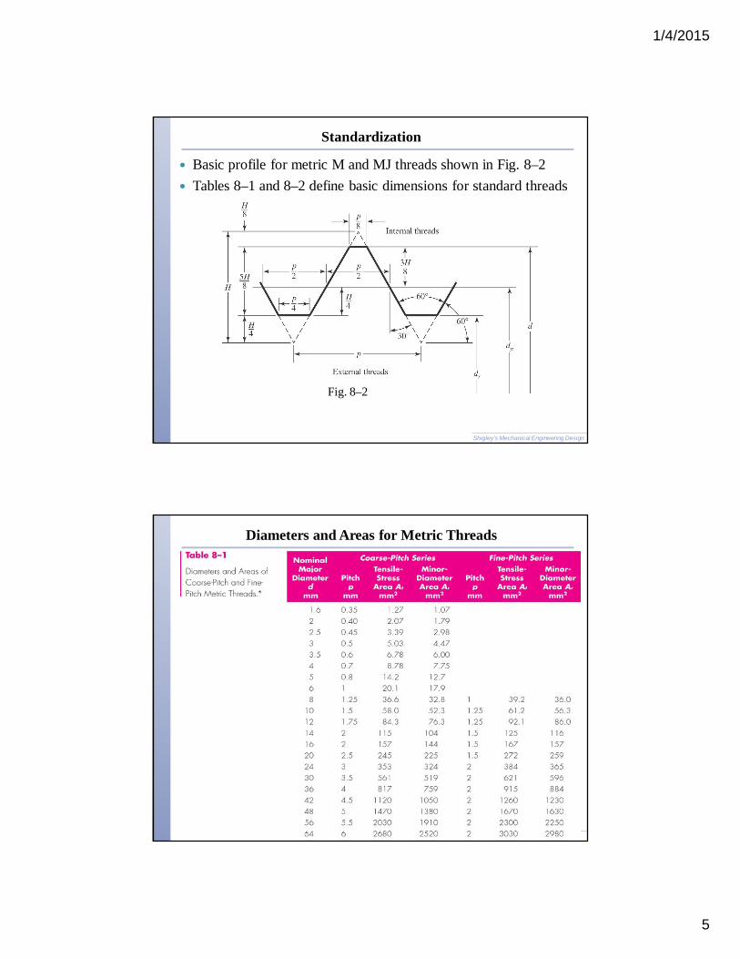
Standardization
Basic profile for metric M and MJ threads shown in Fig. 8–2 Tables 8–1 and 8–2 define basic dimensions for standard threads
Fig. 8–2
Shigley’s Mechanical Engineering Design
Diameters and Areas for Metric Threads
1/4/2015
6
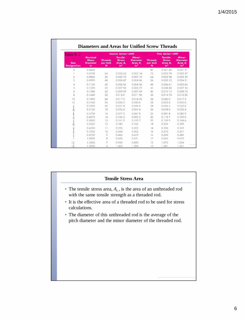
Diameters and Areas for Unified Screw ThreadsTable 8–2
Tensile Stress Area
• The tensile stress area, At , is the area of an unthreaded rod with the same tensile strength as a threaded rod.
• It is the effective area of a threaded rod to be used for stress calculations.
• The diameter of this unthreaded rod is the average of the pitch diameter and the minor diameter of the threaded rod.

1/4/2015
7
Square and Acme Threads
Square and Acme threads are used when the threads are intended to transmit power
Table 8-3 Preferred Pitches for Acme Threads
Fig. 8–3
Mechanics of Power Screws
Power screw◦ Used to change angular motion into
linear motion◦ Usually transmits power◦ Examples include presses, jacks,
lead screw on lathe
Fig. 8–4
1/4/2015
8
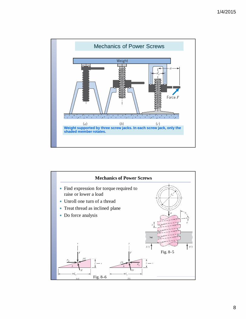
Mechanics of Power ScrewsMechanics of Power Screws
Weight supported by three screw jacks. In each screw jack, only the shaded member rotates.
Mechanics of Power Screws
Find expression for torque required to raise or lower a load
Unroll one turn of a thread Treat thread as inclined plane Do force analysis
Fig. 8–5
Fig. 8–6
1/4/2015
9
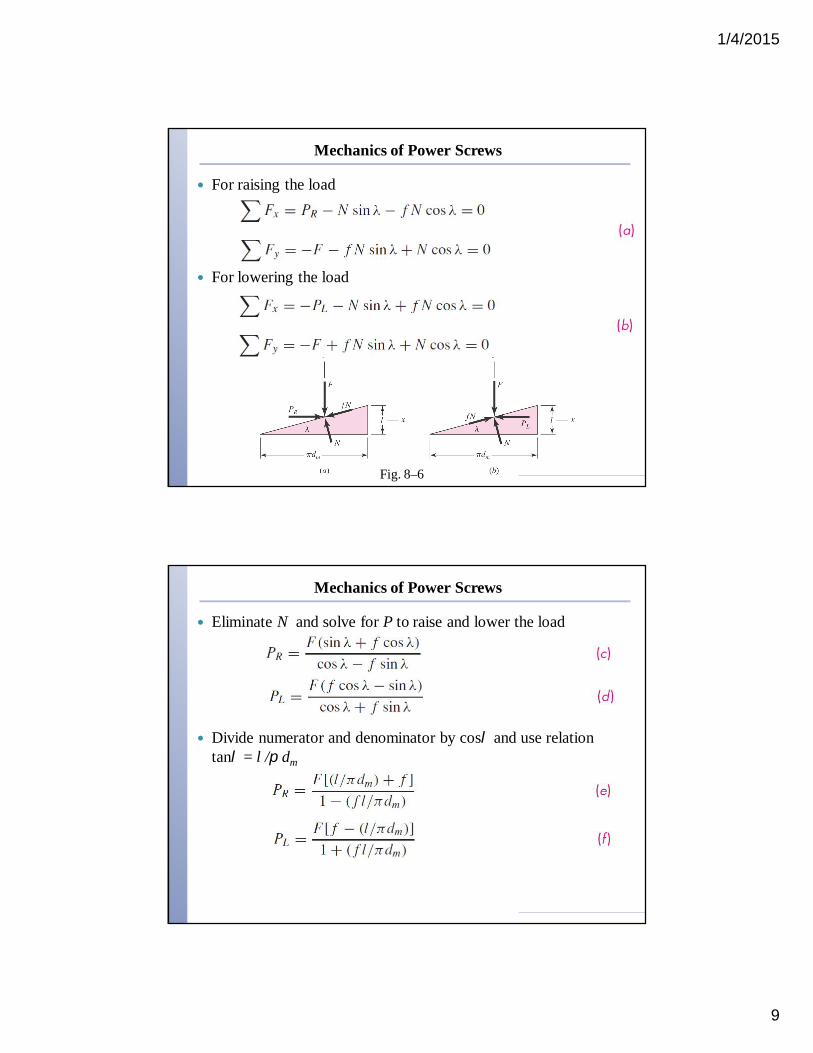
Mechanics of Power Screws
For raising the load
For lowering the load
Fig. 8–6
Mechanics of Power Screws
Eliminate N and solve for P to raise and lower the load
Divide numerator and denominator by cosl and use relation tanl = l /p dm
1/4/2015
10
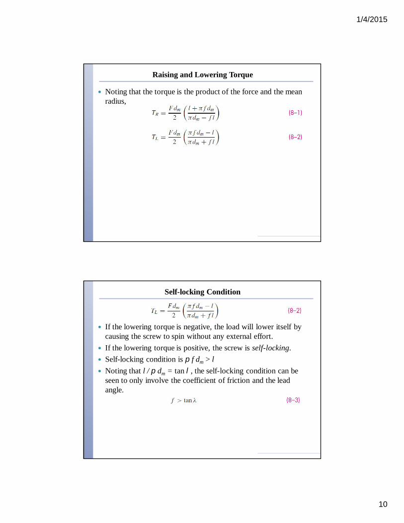
Raising and Lowering Torque
Noting that the torque is the product of the force and the mean radius,
Self-locking Condition
If the lowering torque is negative, the load will lower itself by causing the screw to spin without any external effort.
If the lowering torque is positive, the screw is self-locking. Self-locking condition is p f dm > l Noting that l / p dm = tan l, the self-locking condition can be
seen to only involve the coefficient of friction and the lead angle.
1/4/2015
11
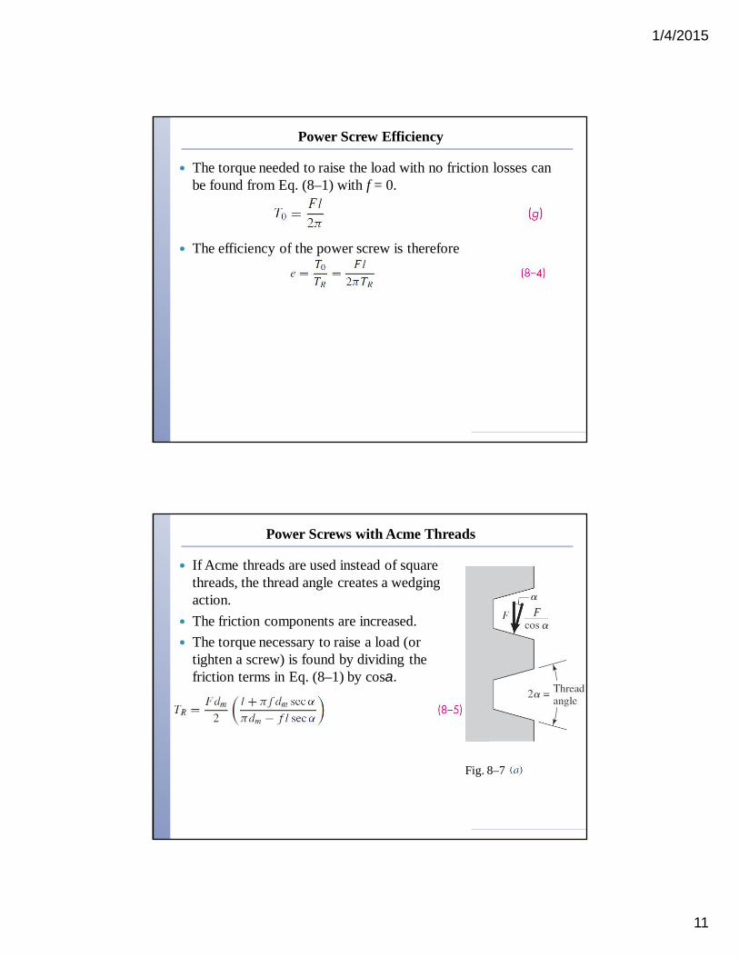
Power Screw Efficiency
The torque needed to raise the load with no friction losses can be found from Eq. (8–1) with f = 0.
The efficiency of the power screw is therefore
Power Screws with Acme Threads
If Acme threads are used instead of square threads, the thread angle creates a wedging action.
The friction components are increased. The torque necessary to raise a load (or
tighten a screw) is found by dividing the friction terms in Eq. (8–1) by cosa.
Fig. 8–7
1/4/2015
12
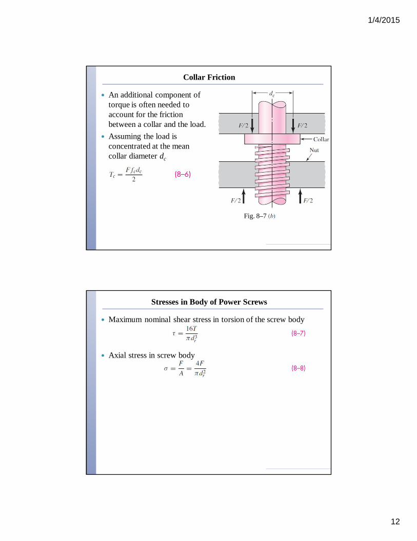
Collar Friction
An additional component of torque is often needed to account for the friction between a collar and the load.
Assuming the load is concentrated at the mean collar diameter dc
Fig. 8–7
Stresses in Body of Power Screws
Maximum nominal shear stress in torsion of the screw body
Axial stress in screw body
1/4/2015
13
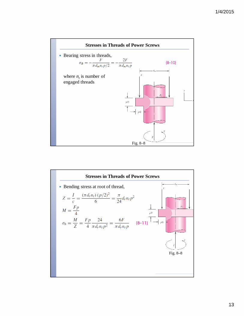
Stresses in Threads of Power Screws
Bearing stress in threads,
where nt is number of engaged threads
Fig. 8–8
Stresses in Threads of Power Screws
Bending stress at root of thread,
Fig. 8–8

1/4/2015
14
Stresses in Threads of Power Screws
Transverse shear stress at center of root of thread,
Fig. 8–8
Stresses in Threads of Power Screws
Consider stress element at the top of the root “plane”
Obtain von Mises stress from Eq. (5–14),
1/4/2015
15
Thread Deformation in Screw-Nut Combination
Power screw thread is in compression, causing elastic shortening of screw thread pitch.
Engaging nut is in tension, causing elastic lengthening of the nut thread pitch.
Consequently, the engaged threads cannot share the load equally. Experiments indicate the first thread carries 38% of the load, the
second thread 25%, and the third thread 18%. The seventh thread is free of load.
To find the largest stress in the first thread of a screw-nut combination, use 0.38F in place of F, and set nt = 1.
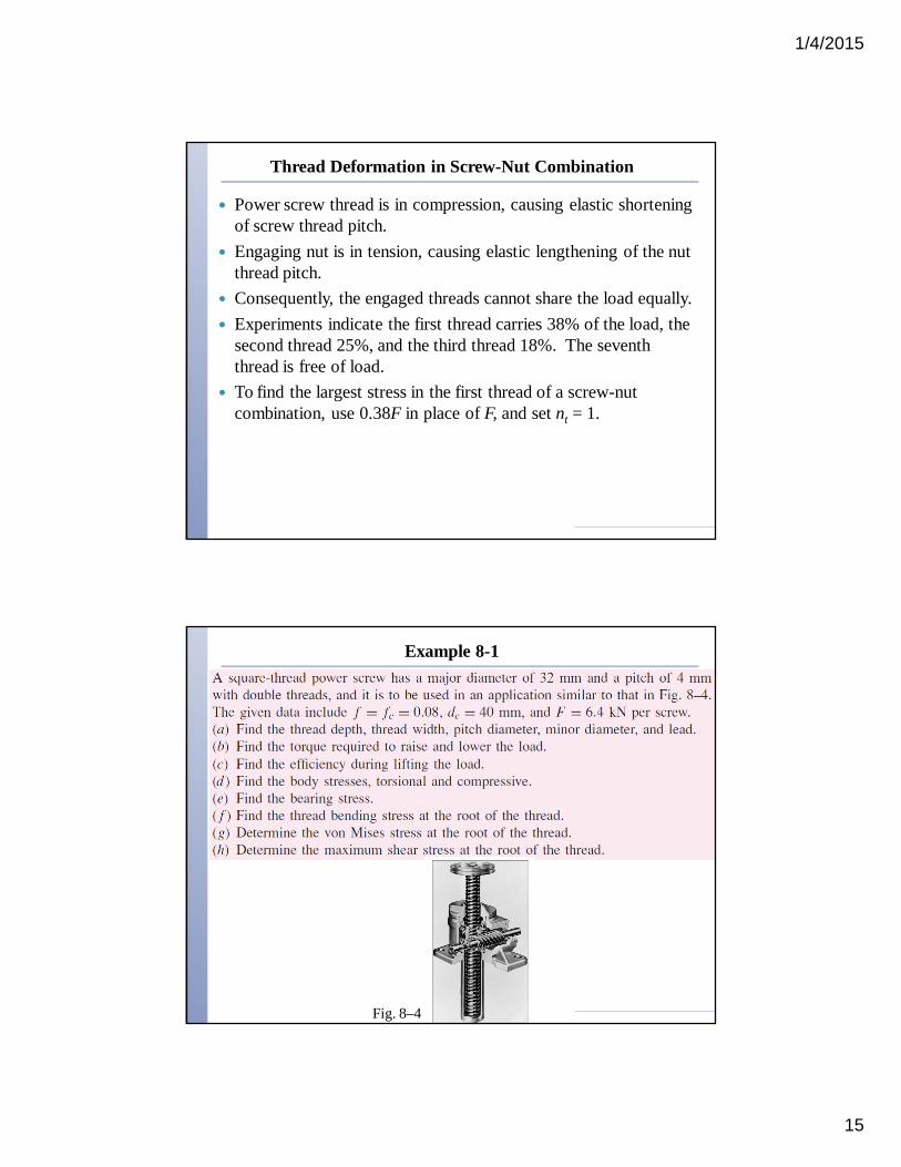
Example 8-1
Fig. 8–4
1/4/2015
16
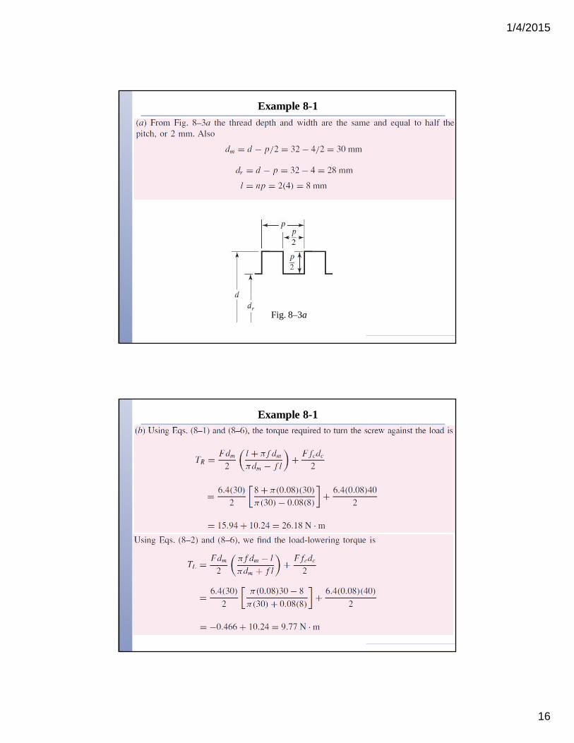
Example 8-1
Fig. 8–3a
Example 8-1
1/4/2015
17
Example 8-1
Example 8-1
1/4/2015
18
Example 8-1
Example 8-1

1/4/2015
19
Example 8-1
Power Screw Safe Bearing Pressure
1/4/2015
20
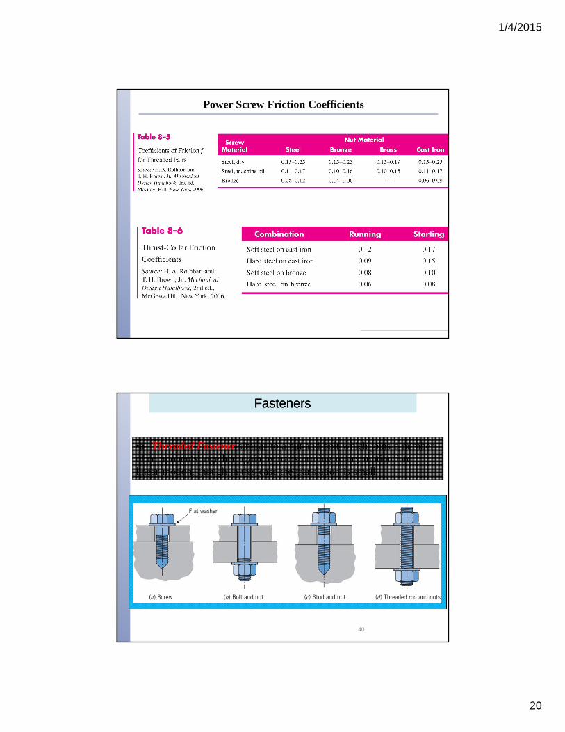
Power Screw Friction Coefficients
FastenersFasteners
•a Threaded Fastener similar to a nut and bolt which joins a number of components together again by transforming rotary motion into linear motion, though in this case the translation is small.
40
1/4/2015
21
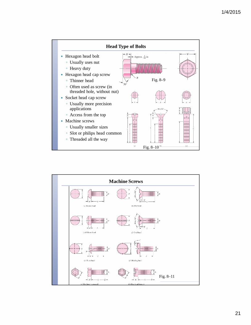
Head Type of Bolts
Hexagon head bolt◦ Usually uses nut◦ Heavy duty
Hexagon head cap screw◦ Thinner head◦ Often used as screw (in
threaded hole, without nut) Socket head cap screw◦ Usually more precision
applications◦ Access from the top
Machine screws◦ Usually smaller sizes◦ Slot or philips head common◦ Threaded all the way
Fig. 8–9
Fig. 8–10
Machine Screws
Fig. 8–11
1/4/2015
22
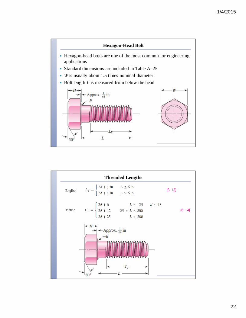
Hexagon-Head Bolt
Hexagon-head bolts are one of the most common for engineering applications
Standard dimensions are included in Table A–25 W is usually about 1.5 times nominal diameter Bolt length L is measured from below the head
Threaded Lengths
Metric
English
1/4/2015
23
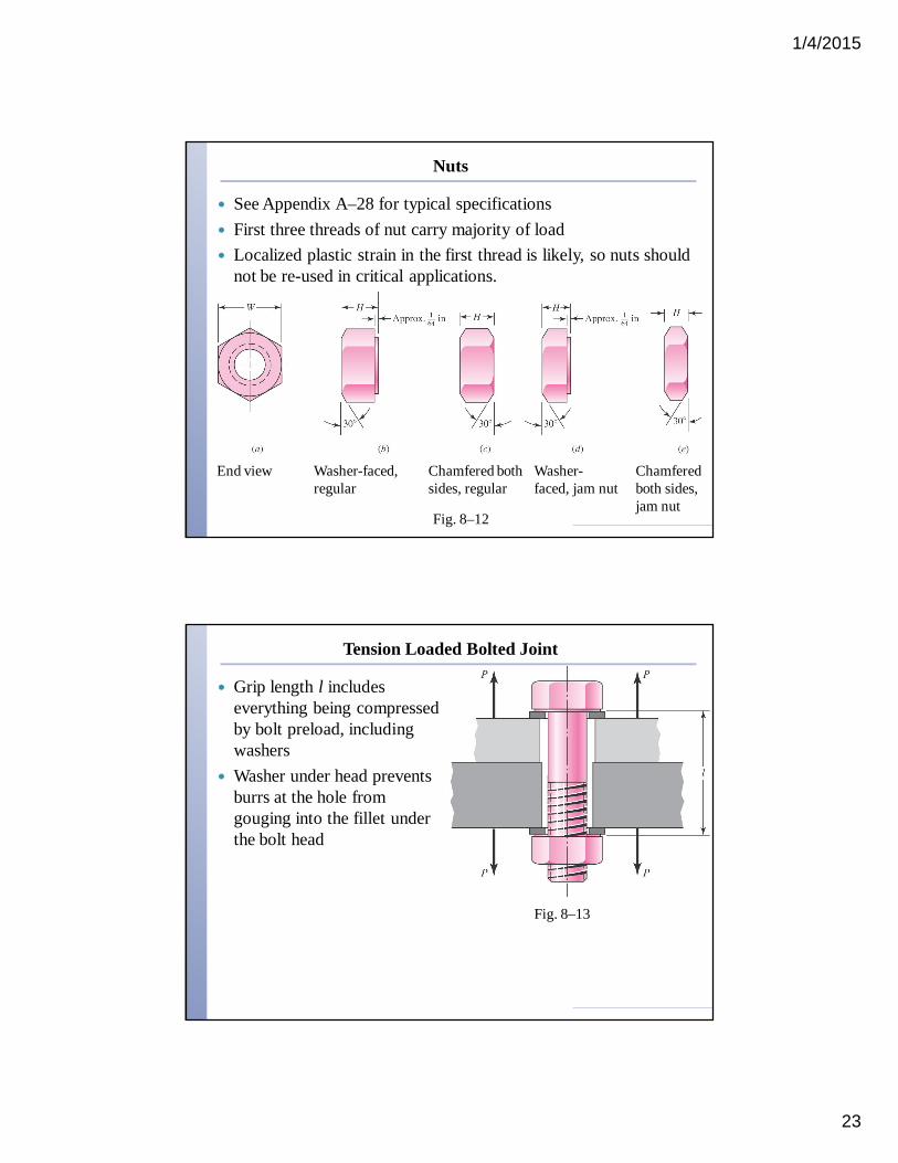
Nuts
See Appendix A–28 for typical specifications First three threads of nut carry majority of load Localized plastic strain in the first thread is likely, so nuts should
not be re-used in critical applications.
End view Washer-faced, regular
Chamfered both sides, regular
Washer-faced, jam nut
Chamfered both sides, jam nut
Fig. 8–12
Tension Loaded Bolted Joint
Grip length l includes everything being compressed by bolt preload, including washers
Washer under head prevents burrs at the hole from gouging into the fillet under the bolt head
Fig. 8–13
1/4/2015
24
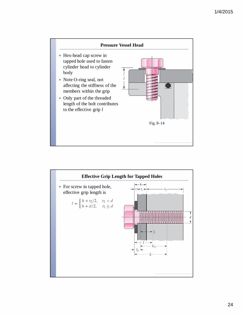
Pressure Vessel Head
Hex-head cap screw in tapped hole used to fasten cylinder head to cylinder body
Note O-ring seal, not affecting the stiffness of the members within the grip
Only part of the threaded length of the bolt contributes to the effective grip l
Fig. 8–14
Effective Grip Length for Tapped Holes
For screw in tapped hole, effective grip length is
1/4/2015
25
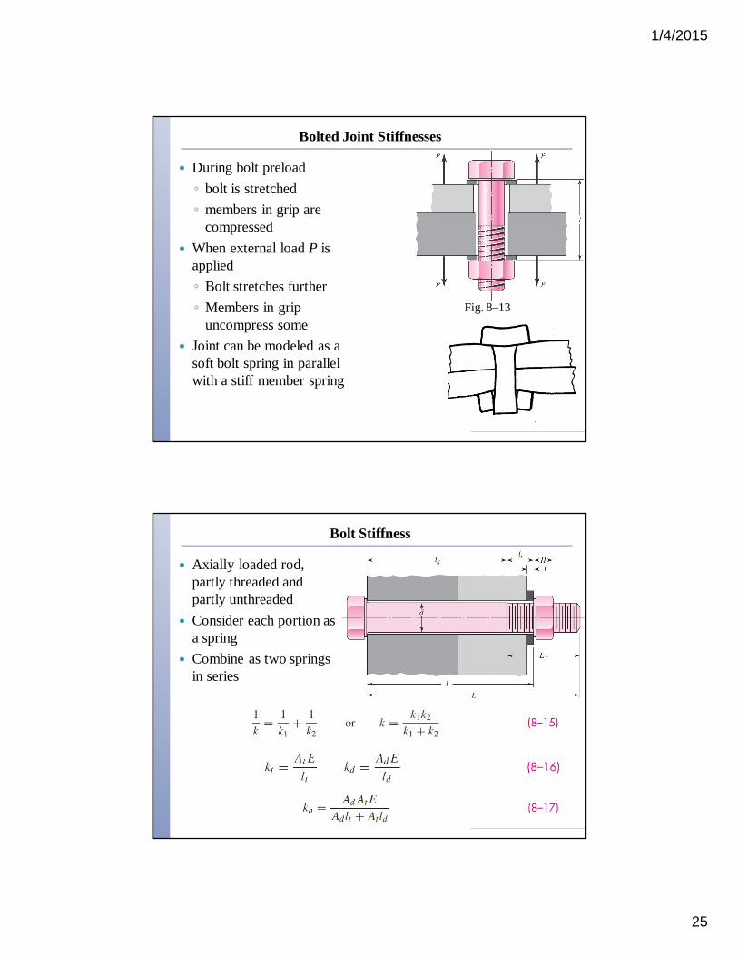
Bolted Joint Stiffnesses
During bolt preload◦ bolt is stretched◦ members in grip are
compressed When external load P is
applied◦ Bolt stretches further◦ Members in grip
uncompress some Joint can be modeled as a
soft bolt spring in parallel with a stiff member spring
Fig. 8–13
Bolt Stiffness
Axially loaded rod, partly threaded and partly unthreaded
Consider each portion as a spring
Combine as two springs in series
1/4/2015
26
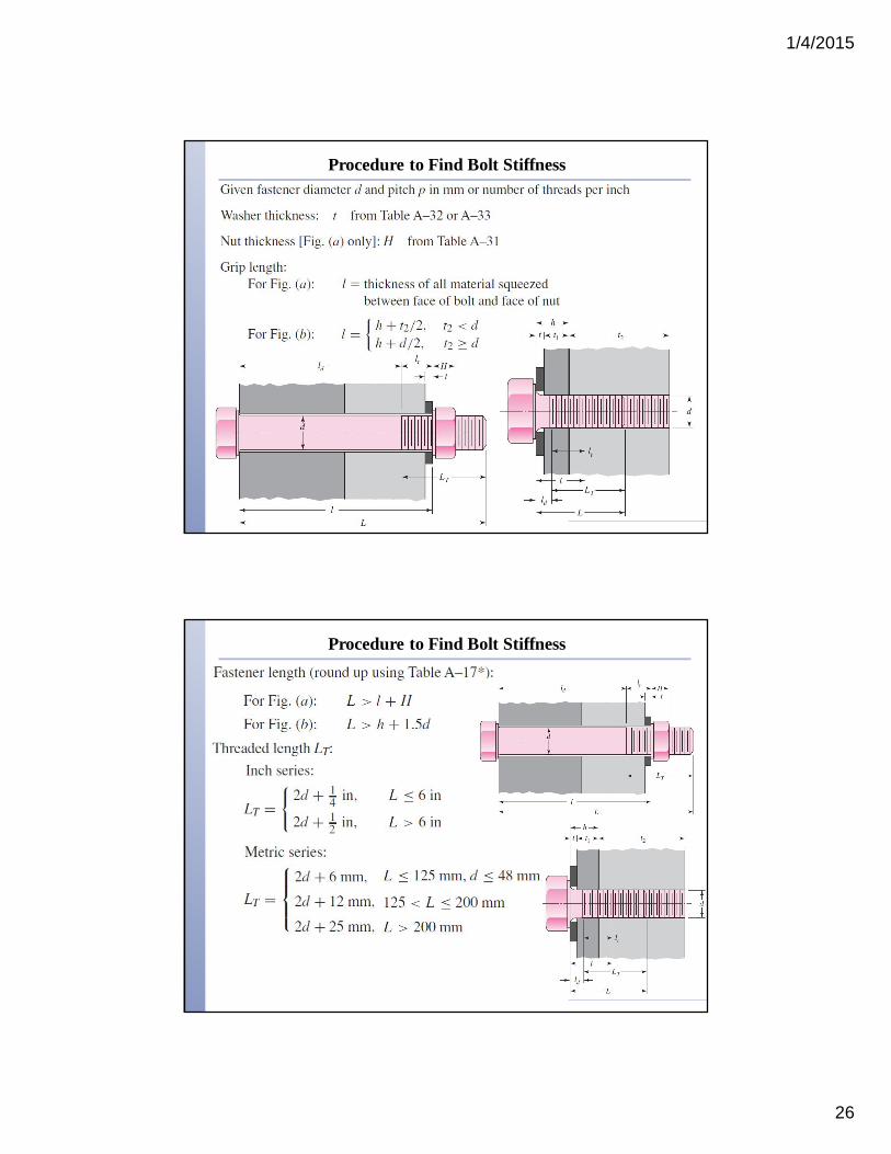
Procedure to Find Bolt Stiffness
Procedure to Find Bolt Stiffness
1/4/2015
27
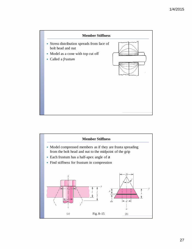
Member Stiffness
Stress distribution spreads from face of bolt head and nut
Model as a cone with top cut off Called a frustum
Member Stiffness
Model compressed members as if they are frusta spreading from the bolt head and nut to the midpoint of the grip
Each frustum has a half-apex angle of a Find stiffness for frustum in compression
Fig. 8–15

1/4/2015
28
Member Stiffness
Member Stiffness
With typical value of a = 30º,
Use Eq. (8–20) to find stiffness for each frustum Combine all frusta as springs in series
Fig. 8–15b
1/4/2015
29
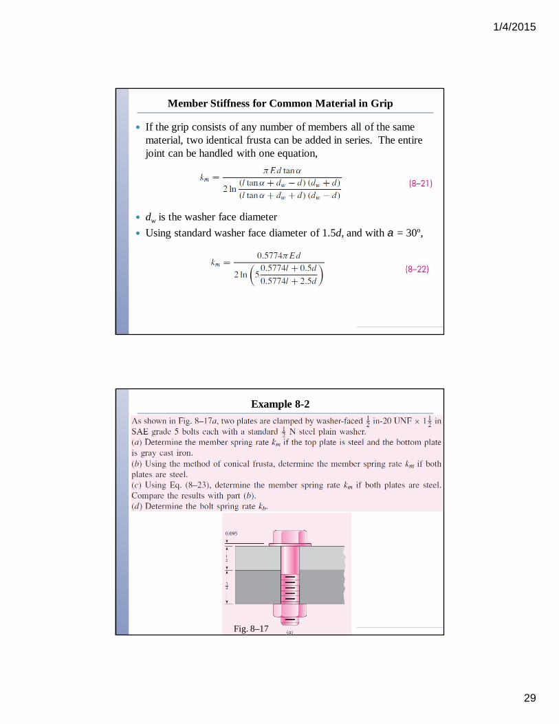
Member Stiffness for Common Material in Grip
If the grip consists of any number of members all of the same material, two identical frusta can be added in series. The entire joint can be handled with one equation,
dw is the washer face diameter Using standard washer face diameter of 1.5d, and with a = 30º,
Example 8-2
Fig. 8–17
1/4/2015
30
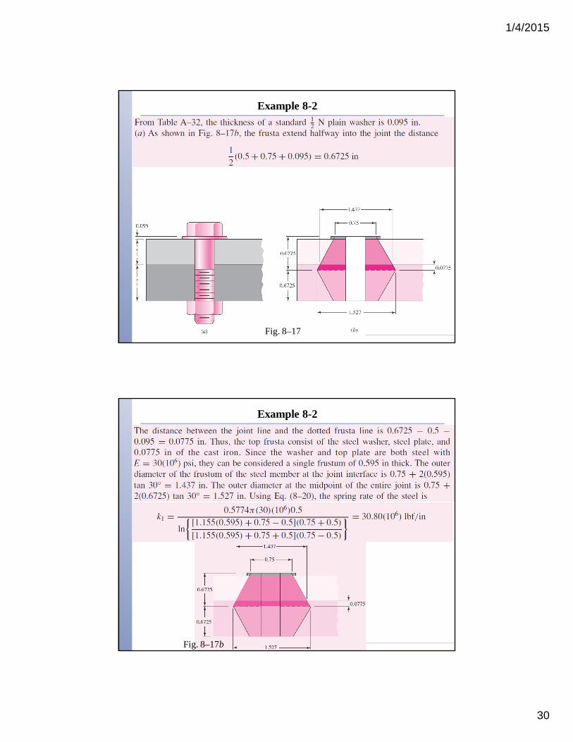
Example 8-2
Fig. 8–17
Example 8-2
Fig. 8–17b
1/4/2015
31
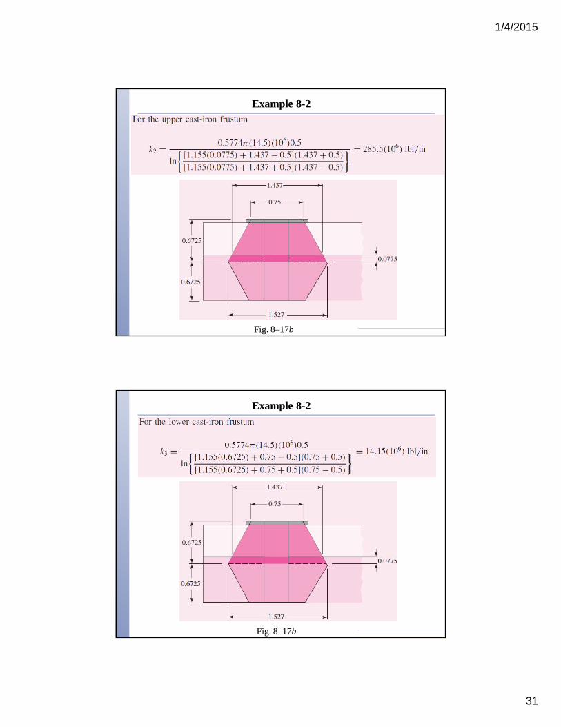
Example 8-2
Fig. 8–17b
Example 8-2
Fig. 8–17b
1/4/2015
32
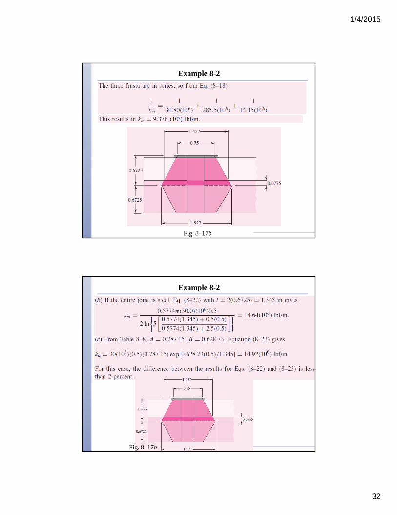
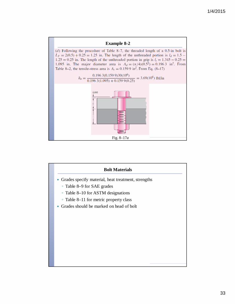
Example 8-2
Fig. 8–17b
Example 8-2
Fig. 8–17b
1/4/2015
33
Example 8-2
Fig. 8–17a
Bolt Materials
Grades specify material, heat treatment, strengths◦ Table 8–9 for SAE grades◦ Table 8–10 for ASTM designations◦ Table 8–11 for metric property class
Grades should be marked on head of bolt

1/4/2015
34
Bolt Materials
Proof load is the maximum load that a bolt can withstand without acquiring a permanent set
Proof strength is the quotient of proof load and tensile-stress area◦ Corresponds to proportional limit◦ Slightly lower than yield strength◦ Typically used for static strength of
bolt Good bolt materials have stress-strain
curve that continues to rise to fracture
Fig. 8–18
SAE Specifications for Steel BoltsTable 8–9
1/4/2015
35
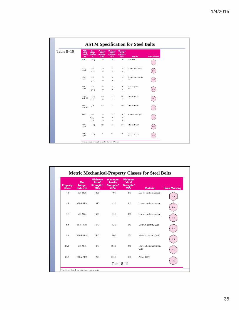
ASTM Specification for Steel BoltsTable 8–10
Metric Mechanical-Property Classes for Steel Bolts
Table 8–11
1/4/2015
36
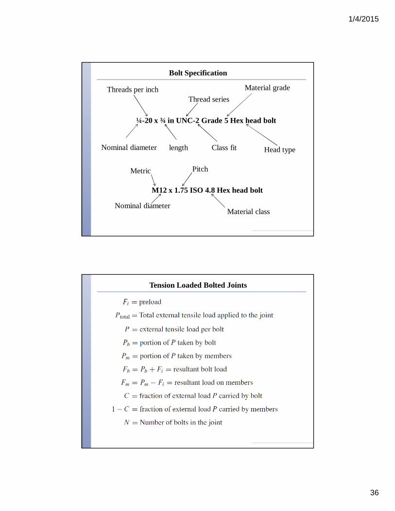
Bolt Specification
Nominal diameter
¼-20 x ¾ in UNC-2 Grade 5 Hex head bolt
Threads per inch
length
Thread series
Class fit
Material grade
Head type
M12 x 1.75 ISO 4.8 Hex head bolt
Metric
Nominal diameter
Pitch
Material class
Tension Loaded Bolted Joints

1/4/2015
37
Tension Loaded Bolted Joints
During bolt preload◦ bolt is stretched◦ members in grip are compressed
When external load P is applied◦ Bolt stretches an additional
amount d◦ Members in grip uncompress same
amount d Fig. 8–13
Stiffness Constant
Since P = Pb + Pm,
C is defined as the stiffness constant of the joint
C indicates the proportion of external load P that the bolt will carry. A good design target is around 0.2.
1/4/2015
38
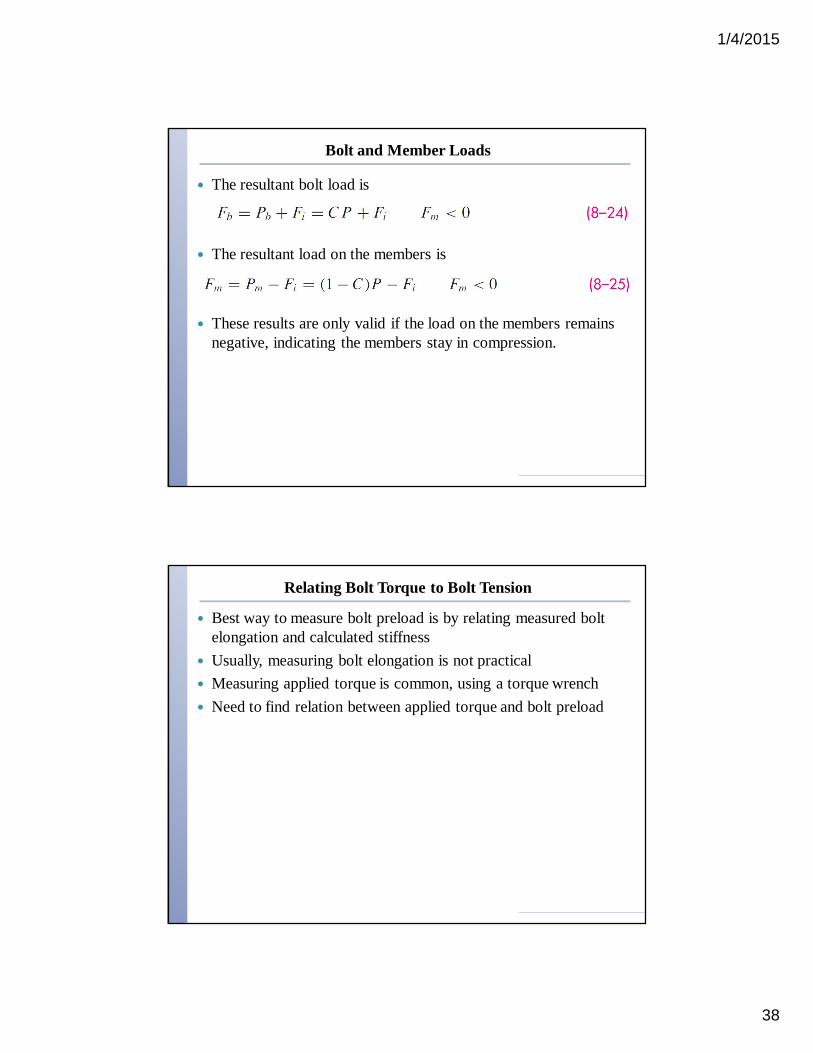
Bolt and Member Loads
The resultant bolt load is
The resultant load on the members is
These results are only valid if the load on the members remains negative, indicating the members stay in compression.
Relating Bolt Torque to Bolt Tension
Best way to measure bolt preload is by relating measured bolt elongation and calculated stiffness
Usually, measuring bolt elongation is not practical Measuring applied torque is common, using a torque wrench Need to find relation between applied torque and bolt preload

1/4/2015
39
Relating Bolt Torque to Bolt Tension
From the power screw equations, Eqs. (8–5) and (8–6), we get
Applying tanl = l/pdm,
Assuming a washer face diameter of 1.5d, the collar diameter isdc = (d + 1.5d)/2 = 1.25d, giving
Relating Bolt Torque to Bolt Tension
Define term in brackets as torque coefficient K
1/4/2015
40
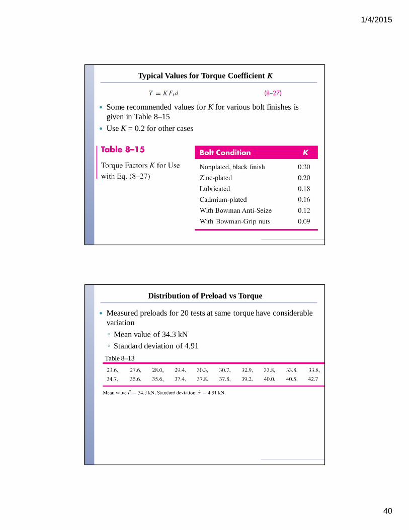
Typical Values for Torque Coefficient K
Some recommended values for K for various bolt finishes is given in Table 8–15
Use K = 0.2 for other cases
Distribution of Preload vs Torque
Measured preloads for 20 tests at same torque have considerable variation◦ Mean value of 34.3 kN◦ Standard deviation of 4.91
Table 8–13
1/4/2015
41
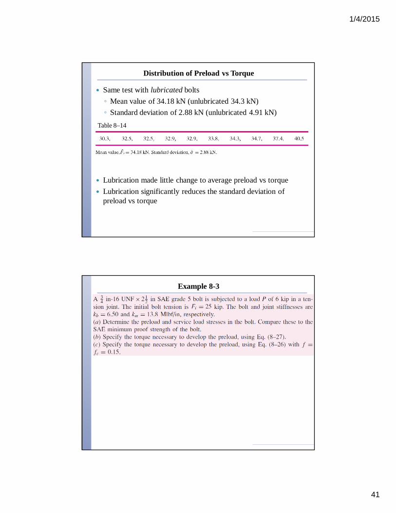
Distribution of Preload vs Torque
Same test with lubricated bolts◦ Mean value of 34.18 kN (unlubricated 34.3 kN)◦ Standard deviation of 2.88 kN (unlubricated 4.91 kN)
Lubrication made little change to average preload vs torque Lubrication significantly reduces the standard deviation of
preload vs torque
Table 8–14
Example 8-3

1/4/2015
42
Example 8-3
Example 8-3
1/4/2015
43
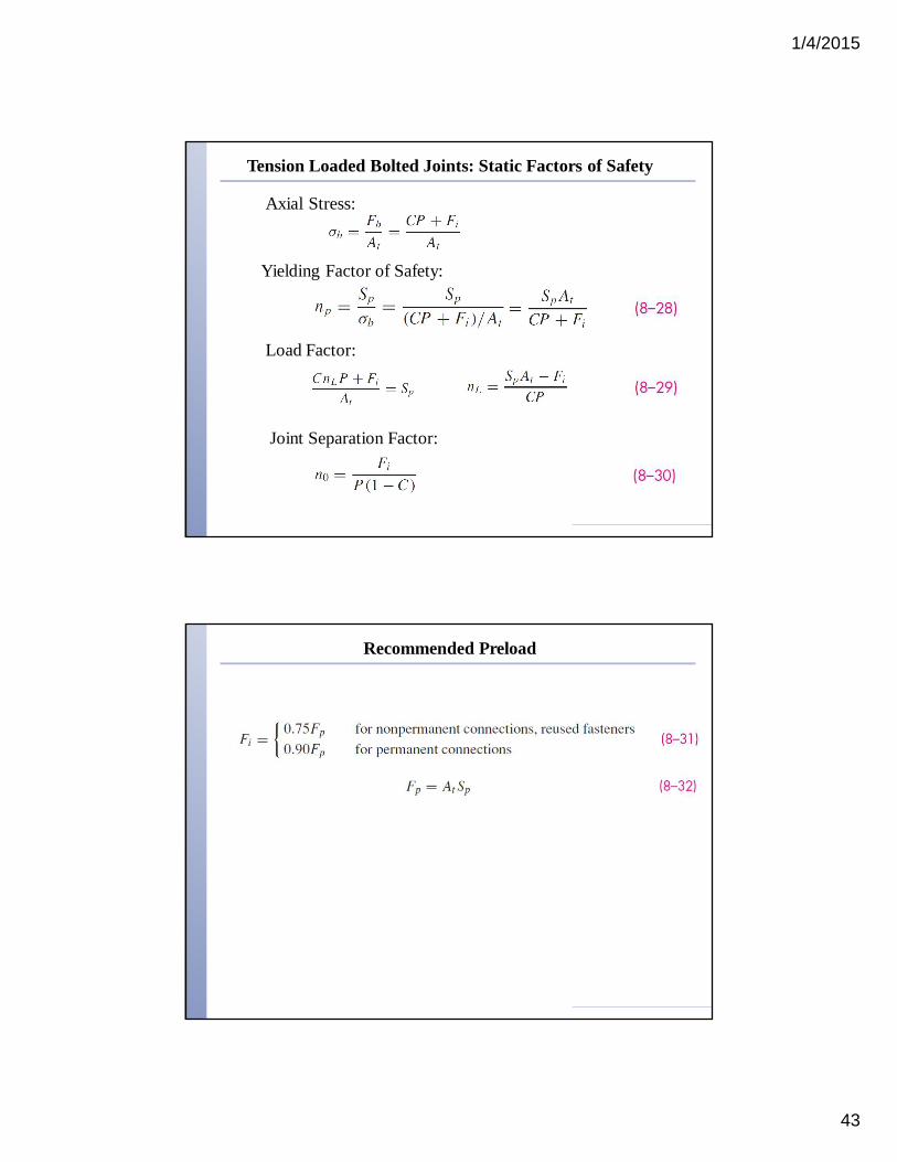
Tension Loaded Bolted Joints: Static Factors of Safety
Axial Stress:
Yielding Factor of Safety:
Load Factor:
Joint Separation Factor:
Recommended Preload
1/4/2015
44
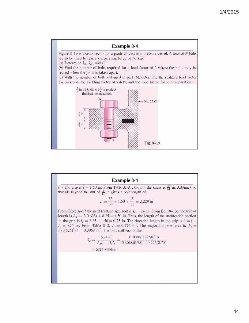
Example 8-4
Fig. 8–19
Example 8-4

1/4/2015
45
Example 8-4
Example 8-4
1/4/2015
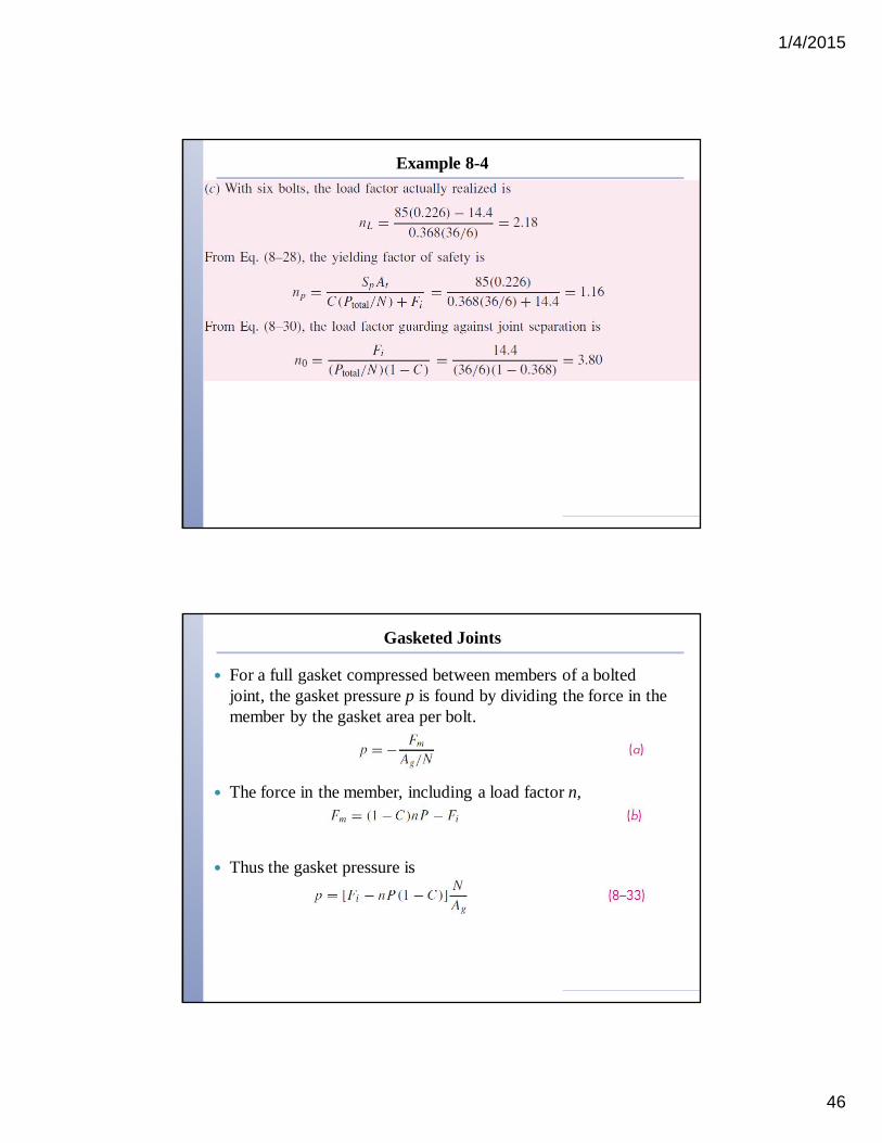
46
Example 8-4
Gasketed Joints
For a full gasket compressed between members of a bolted joint, the gasket pressure p is found by dividing the force in the member by the gasket area per bolt.
The force in the member, including a load factor n,
Thus the gasket pressure is

1/4/2015
47
Gasketed Joints
Uniformity of pressure on the gasket is important Adjacent bolts should no more than six nominal diameters apart
on the bolt circle For wrench clearance, bolts should be at least three diameters
apart This gives a rough rule for bolt spacing around a bolt circle of
diameter Db
Fatigue Loading of Tension Joints
Fatigue methods of Ch. 6 are directly applicable Distribution of typical bolt failures is◦ 15% under the head◦ 20% at the end of the thread◦ 65% in the thread at the nut face
Fatigue stress-concentration factors for threads and fillet are given in Table 8–16

1/4/2015
48
Endurance Strength for Bolts
Bolts are standardized, so endurance strengths are known by experimentation, including all modifiers. See Table 8–17.
Fatigue stress-concentration factor Kf is also included as a reducer of the endurance strength, so it should not be applied to the bolt stresses.
Ch. 6 methods can be used for cut threads.
Fatigue Stresses
With an external load on a per bolt basis fluctuating between Pminand Pmax,
1/4/2015
49
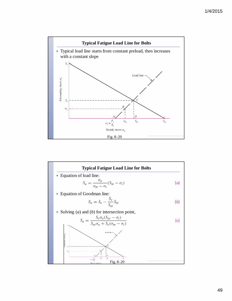
Typical Fatigue Load Line for Bolts
Typical load line starts from constant preload, then increases with a constant slope
Fig. 8–20
Typical Fatigue Load Line for Bolts Equation of load line:
Equation of Goodman line:
Solving (a) and (b) for intersection point,
Fig. 8–20

1/4/2015
50
Fatigue Factor of Safety
Fatigue factor of safety based on Goodman line and constant preload load line,
Other failure curves can be used, following the same approach.
Repeated Load Special Case
Bolted joints often experience repeated load, where external load fluctuates between 0 and Pmax
Setting Pmin = 0 in Eqs. (8-35) and (8-36),
With constant preload load line,
Load line has slope of unity for repeated load case

1/4/2015
51
Repeated Load Special Case
Intersect load line equation with failure curves to get intersection coordinate Sa
Divide Sa by sa to get fatigue factor of safety for repeated load case for each failure curve.
Load line:
Goodman:
Gerber:
ASME-elliptic:
Repeated Load Special Case
Fatigue factor of safety equations for repeated loading, constant preload load line, with various failure curves:
Goodman:
Gerber:
ASME-elliptic:
1/4/2015
52
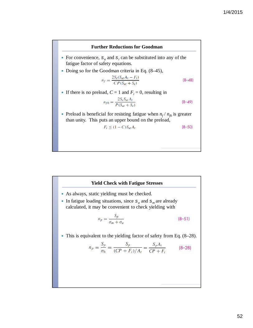
Further Reductions for Goodman
For convenience, sa and si can be substituted into any of the fatigue factor of safety equations.
Doing so for the Goodman criteria in Eq. (8–45),
If there is no preload, C = 1 and Fi = 0, resulting in
Preload is beneficial for resisting fatigue when nf / nf0 is greater than unity. This puts an upper bound on the preload,
Yield Check with Fatigue Stresses
As always, static yielding must be checked. In fatigue loading situations, since sa and sm are already
calculated, it may be convenient to check yielding with
This is equivalent to the yielding factor of safety from Eq. (8–28).
1/4/2015
53
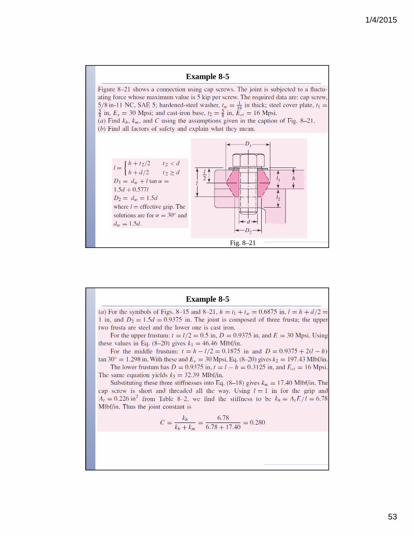
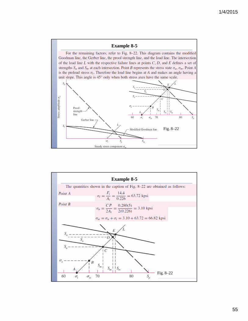
Example 8-5
Fig. 8–21
Example 8-5

1/4/2015
54
Example 8-5
Example 8-5
1/4/2015
55
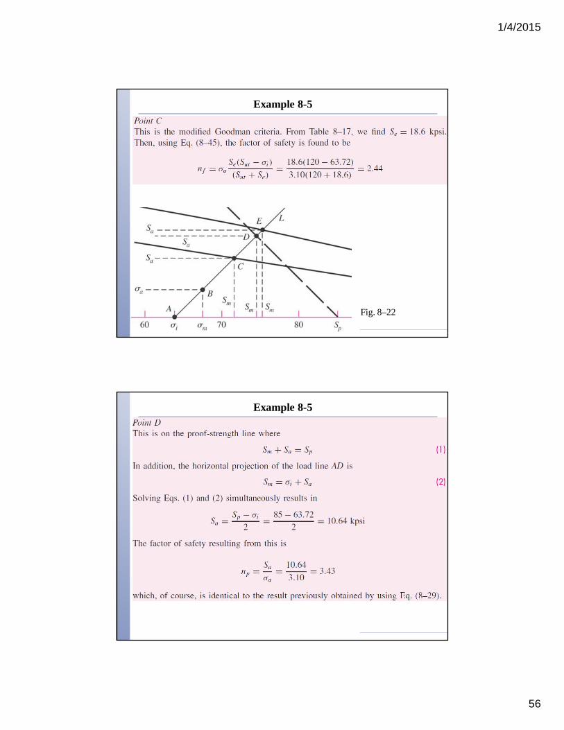
Example 8-5
Fig. 8–22
Example 8-5
Fig. 8–22
1/4/2015
56
Example 8-5
Fig. 8–22
Example 8-5
1/4/2015
57
Example 8-5
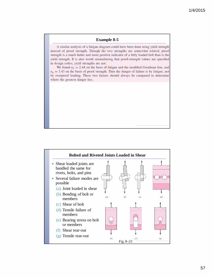
Bolted and Riveted Joints Loaded in Shear
Shear loaded joints are handled the same for rivets, bolts, and pins
Several failure modes are possible(a) Joint loaded in shear(b) Bending of bolt or
members(c) Shear of bolt(d) Tensile failure of
members(e) Bearing stress on bolt
or members(f) Shear tear-out(g) Tensile tear-out
Fig. 8–23
1/4/2015
58
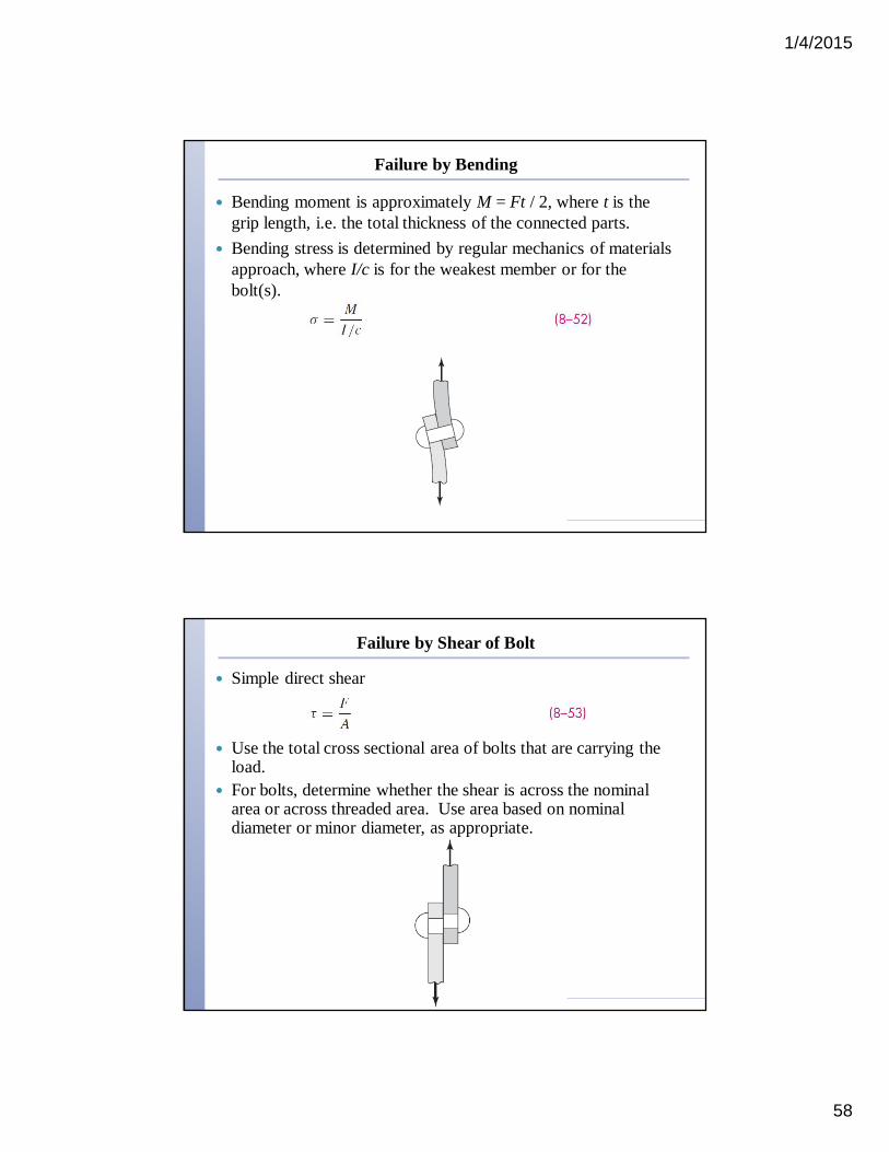
Failure by Bending
Bending moment is approximately M = Ft / 2, where t is the grip length, i.e. the total thickness of the connected parts.
Bending stress is determined by regular mechanics of materials approach, where I/c is for the weakest member or for the bolt(s).
Failure by Shear of Bolt
Simple direct shear
Use the total cross sectional area of bolts that are carrying the load.
For bolts, determine whether the shear is across the nominal area or across threaded area. Use area based on nominal diameter or minor diameter, as appropriate.
1/4/2015
59
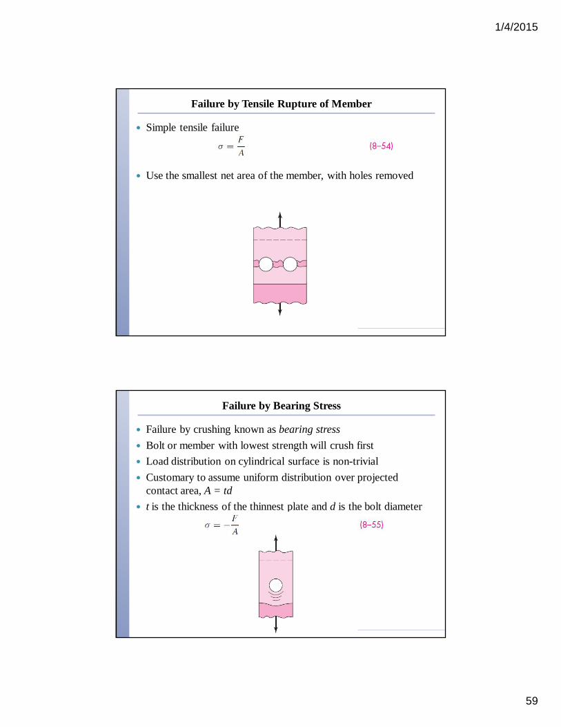
Failure by Tensile Rupture of Member
Simple tensile failure
Use the smallest net area of the member, with holes removed
Failure by Bearing Stress
Failure by crushing known as bearing stress Bolt or member with lowest strength will crush first Load distribution on cylindrical surface is non-trivial Customary to assume uniform distribution over projected
contact area, A = td t is the thickness of the thinnest plate and d is the bolt diameter

1/4/2015
60
Failure by Shear-out or Tear-out
Edge shear-out or tear-out is avoided by spacing bolts at least 1.5 diameters away from the edge
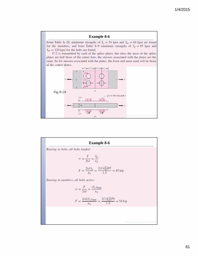
Example 8-6
Fig. 8–24
1/4/2015
61
Example 8-6
Fig. 8–24
Example 8-6
1/4/2015
62
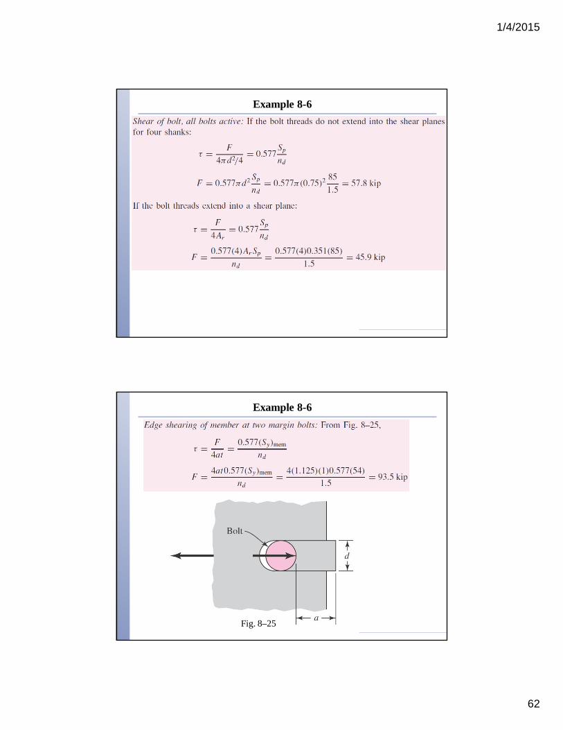
Example 8-6
Example 8-6
Fig. 8–25

1/4/2015
63
Example 8-6
Shear Joints with Eccentric Loading
Eccentric loading is when the load does not pass along a line of symmetry of the fasteners.
Requires finding moment about centroid of bolt pattern Centroid location
Fig. 8–27a
1/4/2015
64
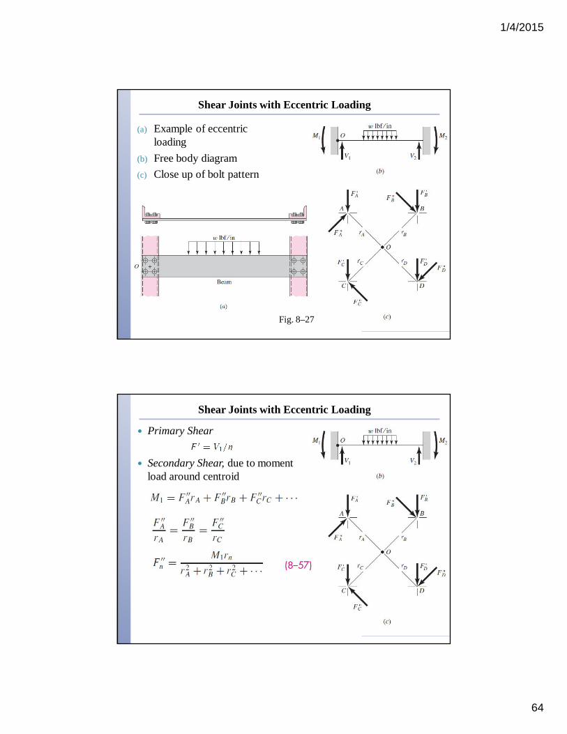
Shear Joints with Eccentric Loading
(a) Example of eccentric loading
(b) Free body diagram(c) Close up of bolt pattern
Fig. 8–27
Shear Joints with Eccentric Loading
Primary Shear
Secondary Shear, due to moment load around centroid
1/4/2015
65
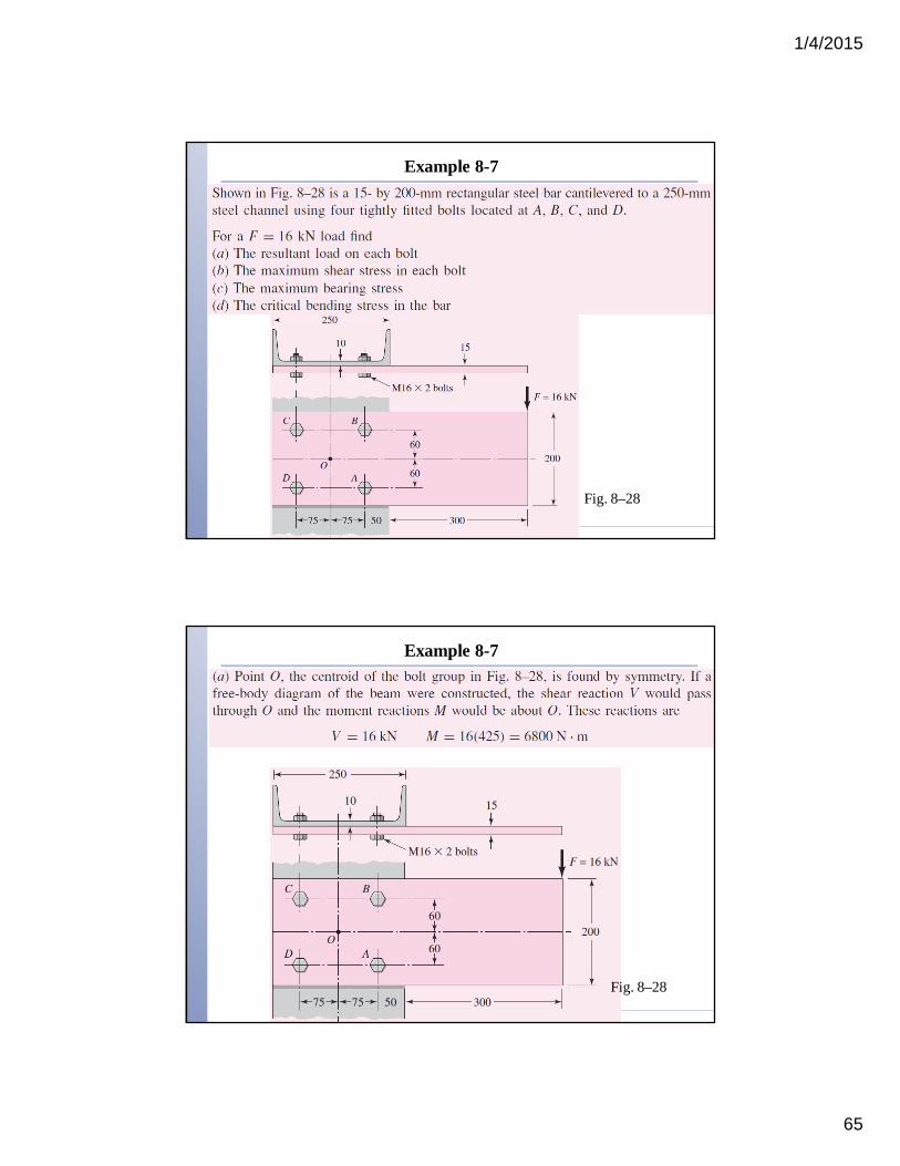
Example 8-7
Fig. 8–28
Example 8-7
Fig. 8–28

1/4/2015
66
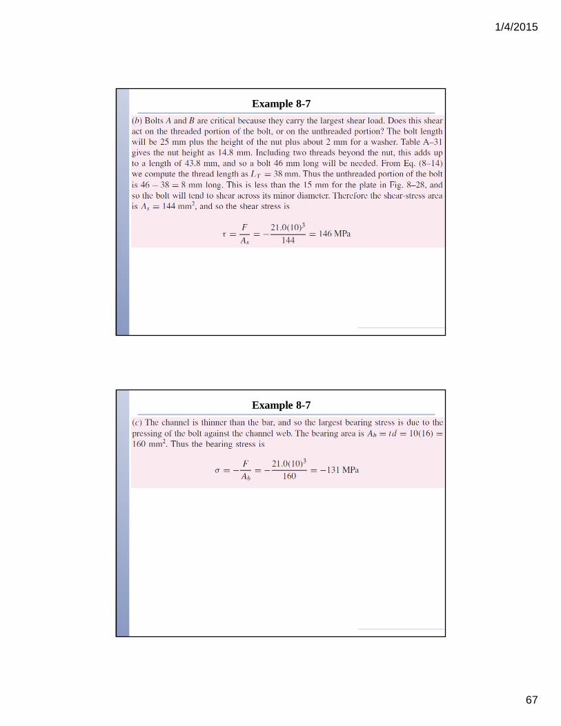
Example 8-7
Fig. 8–29
Example 8-7
1/4/2015
67
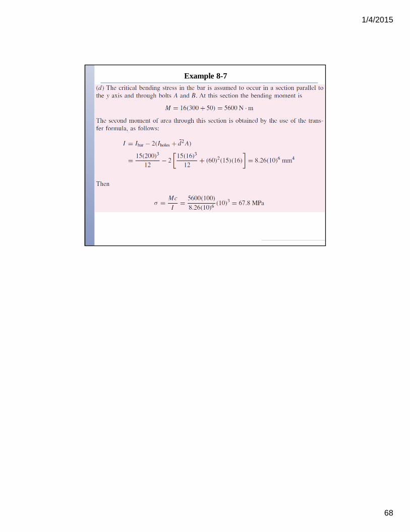
Example 8-7
Example 8-7
1/4/2015
68
Example 8-7