components for definitive prostheses - geocitiescomponents for definitive prostheses the components...
TRANSCRIPT
Physiotherapy Depts, SWAHS (Western Cluster) Fitzsmions, Clark, Symonds, Navarrete, Lees, Saad, Shatford, Forde, & Lee. 35
Components for Definitive Prostheses The components described here are those commonly seen at amputee clinic at Governor Phillip, plus brief descriptions on new technology that clients may ask about. The list is far from complete, as there are many manufacturers, with new products being produced as technology improves. Some components are funded by the Artificial Limb Scheme, some are not and must be paid for privately. Note that limbs funded by the ALS will also usually have a charge to the user (~15% up to $200), unless on a pension or certain types of CentreLink cards.
Feet All must serve to absorb the impact of heelstrike, smoothing the transition to foot flat. Have a “toe-break”, simulating the metatarsal heads and allowing smooth roll over the
forefoot & the shoe to bend in a natural fashion. A more rigid toe-break, or carbon fibre inserts will also allow some energy return, permitting some form of push-off and decreasing “knee drop-off” in late stance.
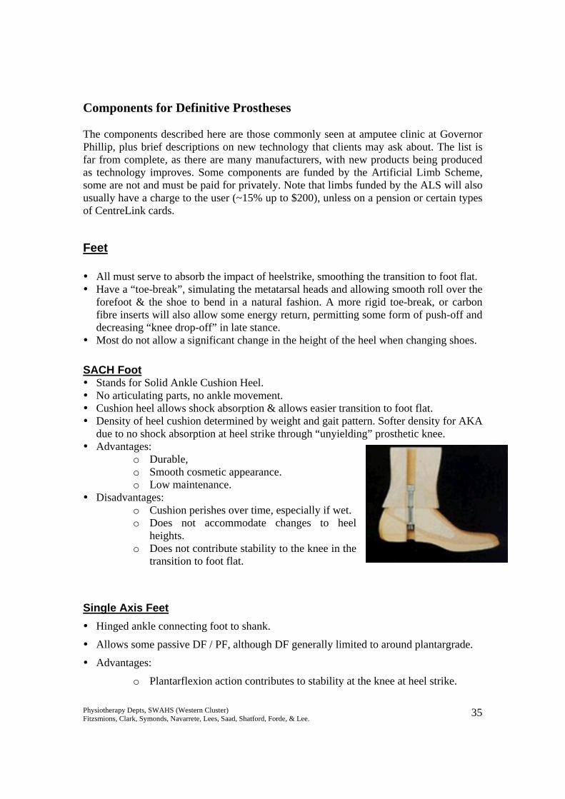
Most do not allow a significant change in the height of the heel when changing shoes. SACH Foot Stands for Solid Ankle Cushion Heel. No articulating parts, no ankle movement. Cushion heel allows shock absorption & allows easier transition to foot flat. Density of heel cushion determined by weight and gait pattern. Softer density for AKA
due to no shock absorption at heel strike through “unyielding” prosthetic knee. Advantages:
o Durable, o Smooth cosmetic appearance. o Low maintenance.
Disadvantages: o Cushion perishes over time, especially if wet. o Does not accommodate changes to heel
heights. o Does not contribute stability to the knee in the
transition to foot flat. Single Axis Feet Hinged ankle connecting foot to shank.
Allows some passive DF / PF, although DF generally limited to around plantargrade.
Advantages:
o Plantarflexion action contributes to stability at the knee at heel strike.
Physiotherapy Depts, SWAHS (Western Cluster) Fitzsmions, Clark, Symonds, Navarrete, Lees, Saad, Shatford, Forde, & Lee. 36
o Better at accommodating ramps / slopes / uneven surfaces.
Disadvantages:
o Mechanical wear & tear – squeaking. o May have a visible ankle joint line. o Are often heavier than SACH feet.
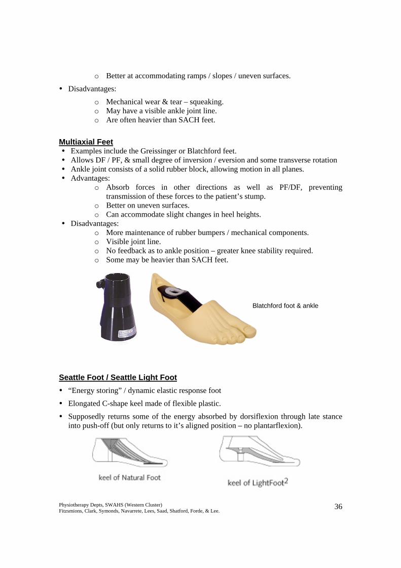
Multiaxial Feet
Examples include the Greissinger or Blatchford feet. Allows DF / PF, & small degree of inversion / eversion and some transverse rotation Ankle joint consists of a solid rubber block, allowing motion in all planes. Advantages:
o Absorb forces in other directions as well as PF/DF, preventing transmission of these forces to the patient’s stump.
o Better on uneven surfaces. o Can accommodate slight changes in heel heights.
Disadvantages: o More maintenance of rubber bumpers / mechanical components. o Visible joint line. o No feedback as to ankle position – greater knee stability required. o Some may be heavier than SACH feet.
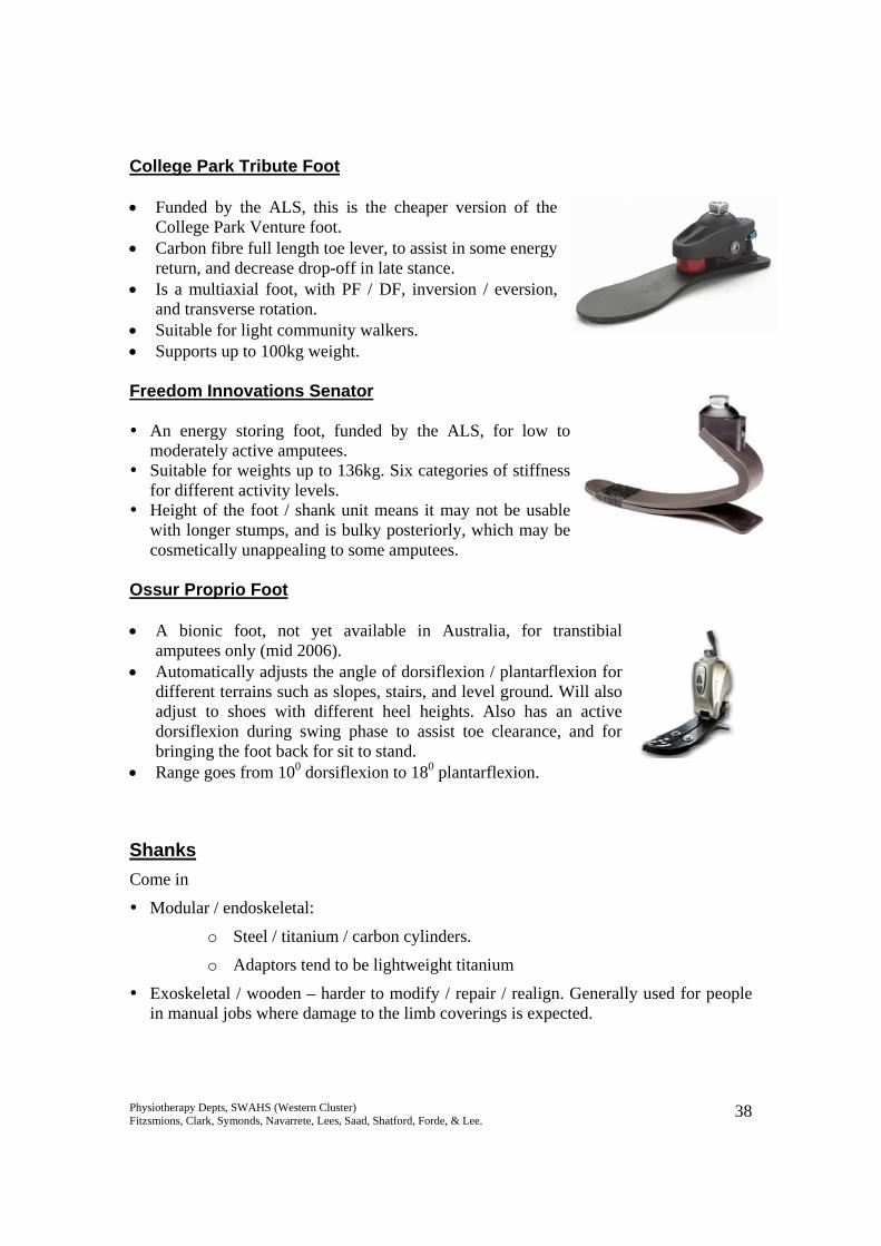
Seattle Foot / Seattle Light Foot “Energy storing” / dynamic elastic response foot
Elongated C-shape keel made of flexible plastic.
Supposedly returns some of the energy absorbed by dorsiflexion through late stance into push-off (but only returns to it’s aligned position – no plantarflexion).
Blatchford foot & ankle
Physiotherapy Depts, SWAHS (Western Cluster) Fitzsmions, Clark, Symonds, Navarrete, Lees, Saad, Shatford, Forde, & Lee. 37
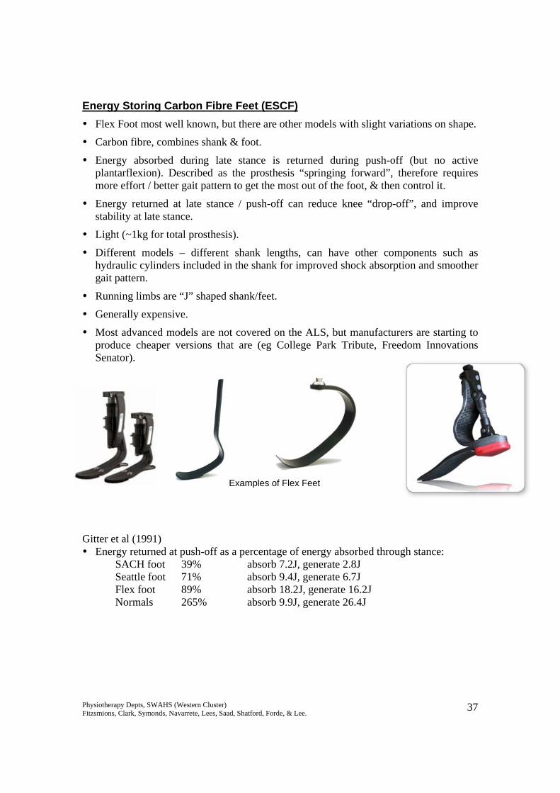
Energy Storing Carbon Fibre Feet (ESCF) Flex Foot most well known, but there are other models with slight variations on shape.
Carbon fibre, combines shank & foot.
Energy absorbed during late stance is returned during push-off (but no active plantarflexion). Described as the prosthesis “springing forward”, therefore requires more effort / better gait pattern to get the most out of the foot, & then control it.
Energy returned at late stance / push-off can reduce knee “drop-off”, and improve stability at late stance.
Light (~1kg for total prosthesis).
Different models – different shank lengths, can have other components such as hydraulic cylinders included in the shank for improved shock absorption and smoother gait pattern.
Running limbs are “J” shaped shank/feet.
Generally expensive.
Most advanced models are not covered on the ALS, but manufacturers are starting to produce cheaper versions that are (eg College Park Tribute, Freedom Innovations Senator).
Gitter et al (1991) Energy returned at push-off as a percentage of energy absorbed through stance:
SACH foot 39% absorb 7.2J, generate 2.8J Seattle foot 71% absorb 9.4J, generate 6.7J Flex foot 89% absorb 18.2J, generate 16.2J Normals 265% absorb 9.9J, generate 26.4J
Examples of Flex Feet
Physiotherapy Depts, SWAHS (Western Cluster) Fitzsmions, Clark, Symonds, Navarrete, Lees, Saad, Shatford, Forde, & Lee. 38
College Park Tribute Foot • Funded by the ALS, this is the cheaper version of the
College Park Venture foot. • Carbon fibre full length toe lever, to assist in some energy
return, and decrease drop-off in late stance. • Is a multiaxial foot, with PF / DF, inversion / eversion,
and transverse rotation. • Suitable for light community walkers. • Supports up to 100kg weight. Freedom Innovations Senator An energy storing foot, funded by the ALS, for low to
moderately active amputees. Suitable for weights up to 136kg. Six categories of stiffness
for different activity levels. Height of the foot / shank unit means it may not be usable
with longer stumps, and is bulky posteriorly, which may be cosmetically unappealing to some amputees.
Ossur Proprio Foot • A bionic foot, not yet available in Australia, for transtibial
amputees only (mid 2006). • Automatically adjusts the angle of dorsiflexion / plantarflexion for
different terrains such as slopes, stairs, and level ground. Will also adjust to shoes with different heel heights. Also has an active dorsiflexion during swing phase to assist toe clearance, and for bringing the foot back for sit to stand.
• Range goes from 100 dorsiflexion to 180 plantarflexion.
Shanks Come in
Modular / endoskeletal:
o Steel / titanium / carbon cylinders.
o Adaptors tend to be lightweight titanium
Exoskeletal / wooden – harder to modify / repair / realign. Generally used for people in manual jobs where damage to the limb coverings is expected.
Physiotherapy Depts, SWAHS (Western Cluster) Fitzsmions, Clark, Symonds, Navarrete, Lees, Saad, Shatford, Forde, & Lee. 39
Knee Joints Must replace the muscles / soft tissue lost:
Flex during early swing Decelerate / limit heel rise Move into extension in late swing fast enough to allow correct foot placement for
heel strike. Maintain stance phase stability.
Most knee joints only allow flexion / extension motion. There is no lateral movement,
although passive rotation can be provided through extra adaptors attached below the sockets if necessary, to reduce torsion forces.
Cannot be actively flexed / extended – generally pendular motion during swing.
Flexion occurs through inertia of the foot lagging behind as the thigh is flexed.
Generally have some mechanism to limit heel lift (friction built into the knee joint) & assist extension through late swing.
Historically stability in stance is through geometric alignment, although new technology is now including use of friction brakes and microprocessors to maintain stance phase stability.
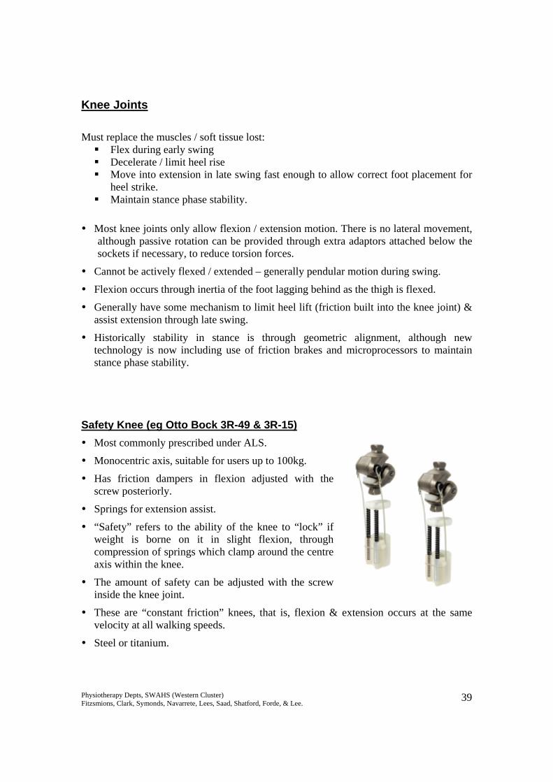
Safety Knee (eg Otto Bock 3R-49 & 3R-15) Most commonly prescribed under ALS.
Monocentric axis, suitable for users up to 100kg.
Has friction dampers in flexion adjusted with the screw posteriorly.
Springs for extension assist.
“Safety” refers to the ability of the knee to “lock” if weight is borne on it in slight flexion, through compression of springs which clamp around the centre axis within the knee.
The amount of safety can be adjusted with the screw inside the knee joint.
These are “constant friction” knees, that is, flexion & extension occurs at the same velocity at all walking speeds.
Steel or titanium.
Physiotherapy Depts, SWAHS (Western Cluster) Fitzsmions, Clark, Symonds, Navarrete, Lees, Saad, Shatford, Forde, & Lee. 40
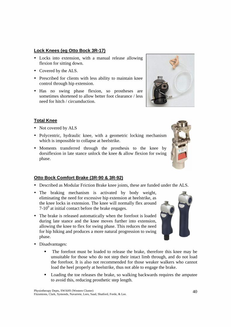
Lock Knees (eg Otto Bock 3R-17) Locks into extension, with a manual release allowing
flexion for sitting down.
Covered by the ALS.
Prescribed for clients with less ability to maintain knee control through hip extension.
Has no swing phase flexion, so prostheses are sometimes shortened to allow better foot clearance / less need for hitch / circumduction.
Total Knee Not covered by ALS
Polycentric, hydraulic knee, with a geometric locking mechanism which is impossible to collapse at heelstrike.
Moments transferred through the prosthesis to the knee by dorsiflexion in late stance unlock the knee & allow flexion for swing phase.
Otto Bock Comfort Brake (3R-90 & 3R-92) Described as Modular Friction Brake knee joints, these are funded under the ALS.
The braking mechanism is activated by body weight, eliminating the need for excessive hip extension at heelstrike, as the knee locks in extension. The knee will normally flex around 7-100 at initial contact before the brake engages.
The brake is released automatically when the forefoot is loaded during late stance and the knee moves further into extension, allowing the knee to flex for swing phase. This reduces the need for hip hiking and produces a more natural progression to swing phase.
Disadvantages:
The forefoot must be loaded to release the brake, therefore this knee may be unsuitable for those who do not step their intact limb through, and do not load the forefoot. It is also not recommended for those weaker walkers who cannot load the heel properly at heelstrike, thus not able to engage the brake.
Loading the toe releases the brake, so walking backwards requires the amputee to avoid this, reducing prosthetic step length.
Physiotherapy Depts, SWAHS (Western Cluster) Fitzsmions, Clark, Symonds, Navarrete, Lees, Saad, Shatford, Forde, & Lee. 41
Suitable for weights up to 125kg. The 3R-90 is recommended for indoor & restricted outdoor users, while the 3R-92 is recommended for unrestricted outdoor walkers.
The 3R-90 has a mechanical spring extension assist, and the 3R-92 has progressively acting pneumatic flexion and extension resistance for variable cadence.
Can be combined with energy storing / returning feet, as the knee is stable throughout stance phase.
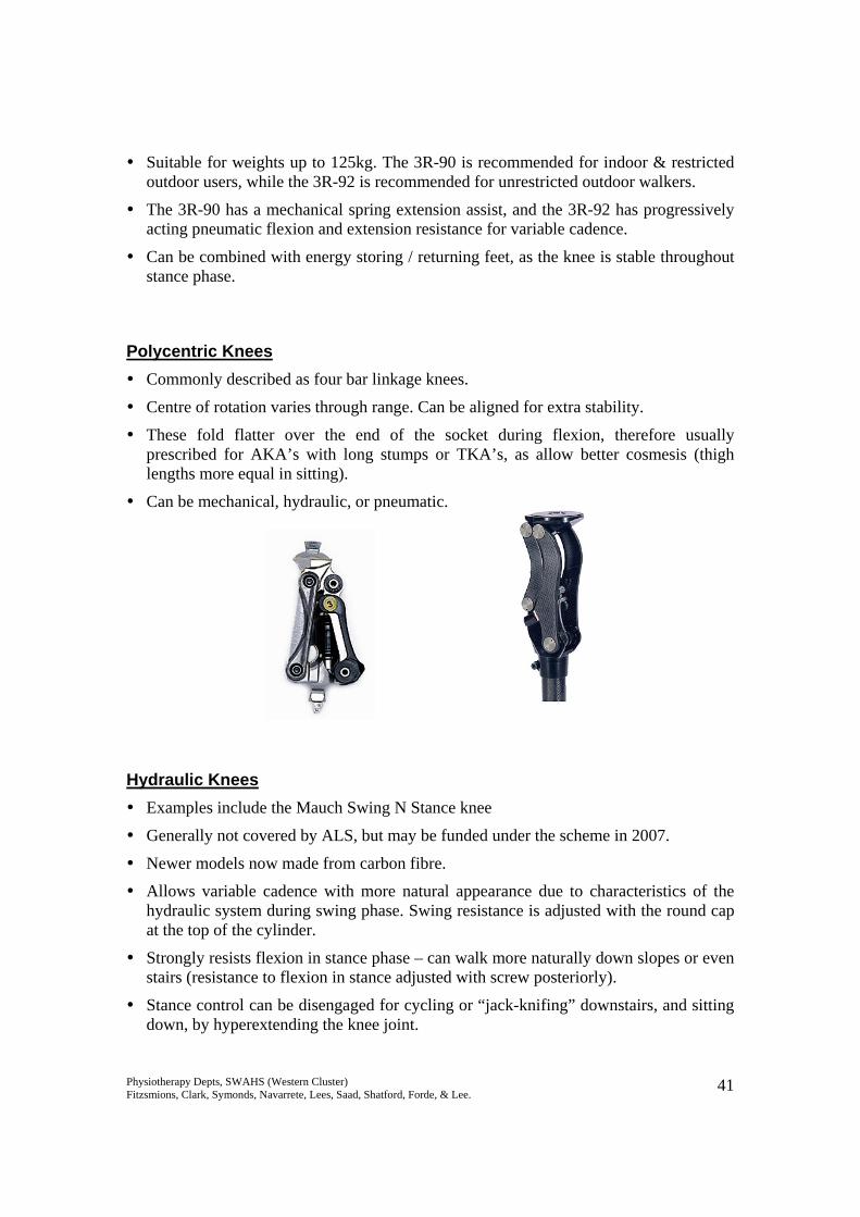
Polycentric Knees Commonly described as four bar linkage knees.
Centre of rotation varies through range. Can be aligned for extra stability.
These fold flatter over the end of the socket during flexion, therefore usually prescribed for AKA’s with long stumps or TKA’s, as allow better cosmesis (thigh lengths more equal in sitting).
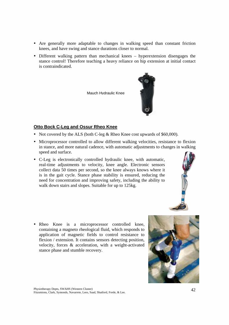
Can be mechanical, hydraulic, or pneumatic. Hydraulic Knees Examples include the Mauch Swing N Stance knee
Generally not covered by ALS, but may be funded under the scheme in 2007.
Newer models now made from carbon fibre.
Allows variable cadence with more natural appearance due to characteristics of the hydraulic system during swing phase. Swing resistance is adjusted with the round cap at the top of the cylinder.
Strongly resists flexion in stance phase – can walk more naturally down slopes or even stairs (resistance to flexion in stance adjusted with screw posteriorly).
Stance control can be disengaged for cycling or “jack-knifing” downstairs, and sitting down, by hyperextending the knee joint.
Physiotherapy Depts, SWAHS (Western Cluster) Fitzsmions, Clark, Symonds, Navarrete, Lees, Saad, Shatford, Forde, & Lee. 42
Are generally more adaptable to changes in walking speed than constant friction knees, and have swing and stance durations closer to normal.
Different walking pattern than mechanical knees – hyperextension disengages the stance control! Therefore teaching a heavy reliance on hip extension at initial contact is contraindicated.
Otto Bock C-Leg and Ossur Rheo Knee Not covered by the ALS (both C-leg & Rheo Knee cost upwards of $60,000).
Microprocessor controlled to allow different walking velocities, resistance to flexion in stance, and more natural cadence, with automatic adjustments to changes in walking speed and surface.
C-Leg is electronically controlled hydraulic knee, with automatic, real-time adjustments to velocity, knee angle. Electronic sensors collect data 50 times per second, so the knee always knows where it is in the gait cycle. Stance phase stability is ensured, reducing the need for concentration and improving safety, including the ability to walk down stairs and slopes. Suitable for up to 125kg.
Rheo Knee is a microprocessor controlled knee, containing a magneto rheological fluid, which responds to application of magnetic fields to control resistance to flexion / extension. It contains sensors detecting position, velocity, forces & acceleration, with a weight-activated stance phase and stumble recovery.
Mauch Hydraulic Knee
Physiotherapy Depts, SWAHS (Western Cluster) Fitzsmions, Clark, Symonds, Navarrete, Lees, Saad, Shatford, Forde, & Lee. 43
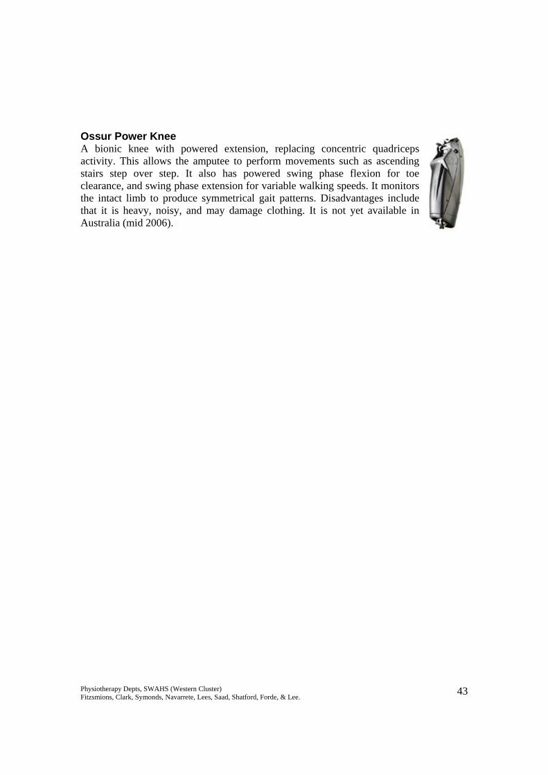
Ossur Power Knee A bionic knee with powered extension, replacing concentric quadriceps activity. This allows the amputee to perform movements such as ascending stairs step over step. It also has powered swing phase flexion for toe clearance, and swing phase extension for variable walking speeds. It monitors the intact limb to produce symmetrical gait patterns. Disadvantages include that it is heavy, noisy, and may damage clothing. It is not yet available in Australia (mid 2006).
Physiotherapy Depts, SWAHS (Western Cluster) Fitzsmions, Clark, Symonds, Navarrete, Lees, Saad, Shatford, Forde, & Lee. 44
Sockets BKA Standard supplied by ALS:
Total contact PTB (patellar tendon bearing) or PTK (patellar tendon kegel), with supracondylar suspension & pelite liner.
Constructed using the same principles as plaster temporary prostheses, ie total contact, patellar tendon bearing.
Supracondylar suspension, which grips the femoral condyles, can also be replaced with a suprapatellar cuff.
Must be total contact, to prevent dependent oedema / pooling of perspiration / vacuum effects on skin. If not rectified, this can lead to skin problems such as verrucous hyperplasia – caused by loss of end contact and reduced hydrostatic pressure.
Non-standard components not supplied by ALS:
Different liners – silicone, urethane. Better at absorbing shear forces & distributing pressure. Users may have some sweating problems, especially initially.
Different suspension mechanisms – suction / vacuum, locking pins, sleeves. Vacuum sockets are felt to reduce pistoning and maintain stump volume, contributing to a more symmetrical gait.
Different weight bearing areas – with urethane liners pressure can be distributed around the whole stump, so sockets are rounder / more natural limb shaped & don’t require patellar shelves or popliteal counter-pressure. This can be advantageous as it is thought that high pressure in the popliteal fossa can cause circulation problems, which is especially a risk in vascular amputees.
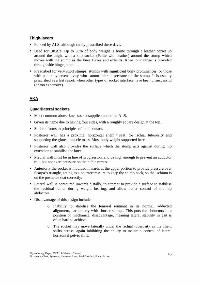
Polyurethane
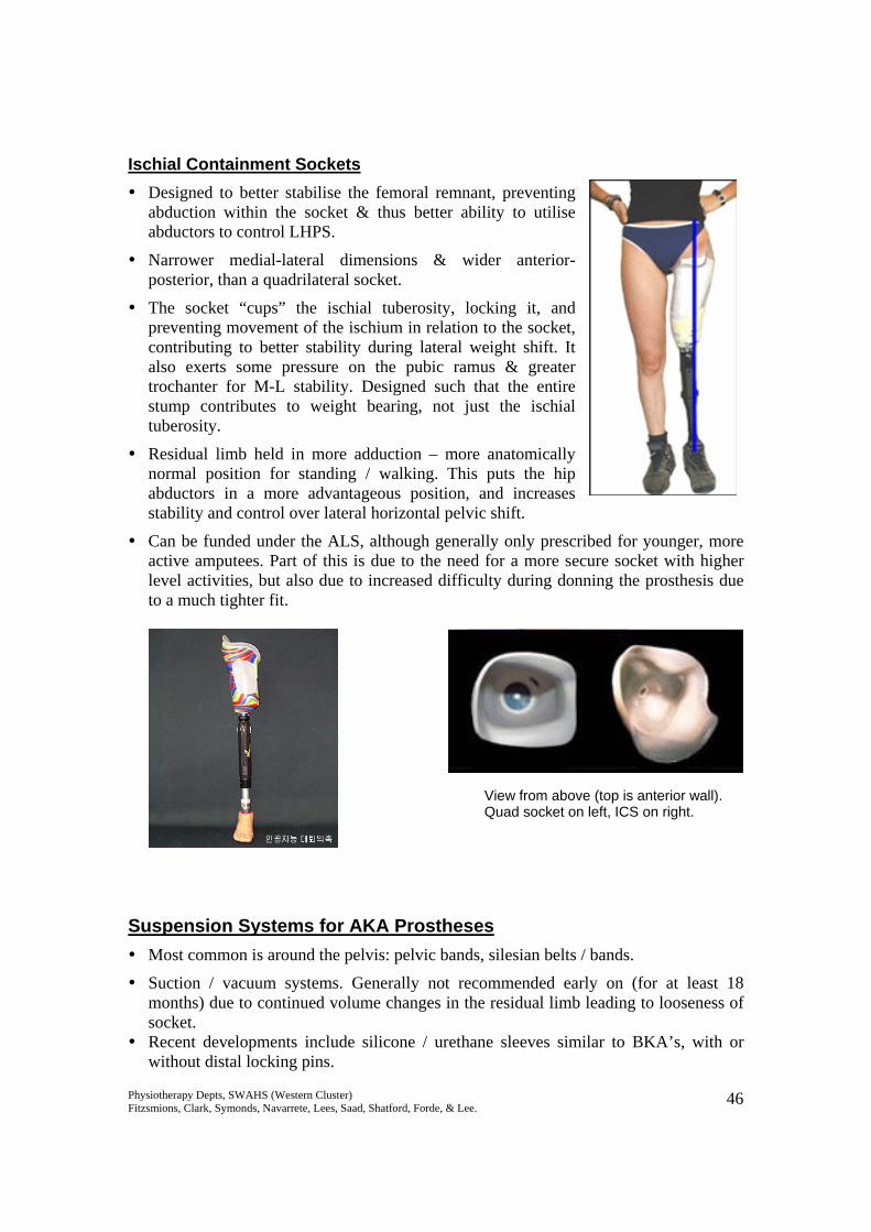
TEC LinerIceross liner with locking pin
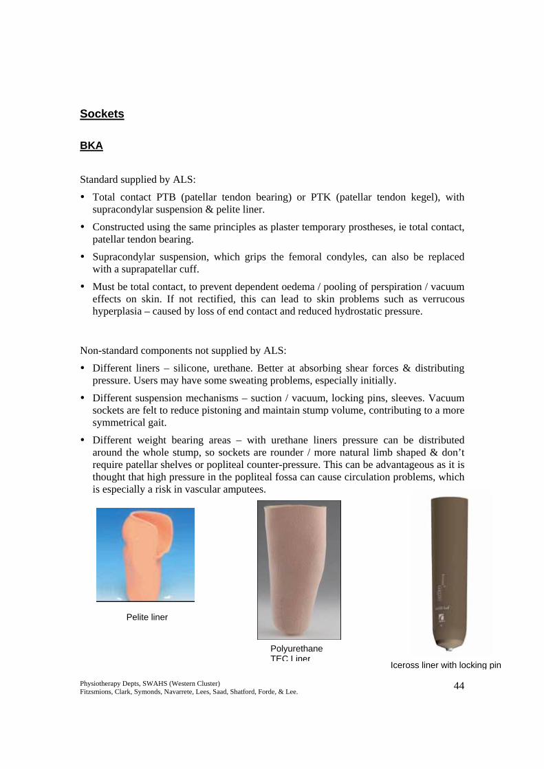
Pelite liner
Physiotherapy Depts, SWAHS (Western Cluster) Fitzsmions, Clark, Symonds, Navarrete, Lees, Saad, Shatford, Forde, & Lee. 45
Thigh-lacers Funded by ALS, although rarely prescribed these days.
Used for BKA’s. Up to 60% of body weight is borne through a leather corset up around the thigh, with a slip socket (Pelite with leather) around the stump which moves with the stump as the knee flexes and extends. Knee joint range is provided through side hinge joints.
Prescribed for very short stumps, stumps with significant bony prominences, or those with pain / hypersensitivity who cannot tolerate pressure on the stump. It is usually prescribed as a last resort, when other types of socket interface have been unsuccessful (or too expensive).
AKA Quadrilateral sockets Most common above-knee socket supplied under the ALS.
Given its name due to having four sides, with a roughly square design at the top.
Still conforms to principles of total contact.
Posterior wall has a proximal horizontal shelf / seat, for ischial tuberosity and supporting the gluteal muscle mass. Most body weight supported here.
Posterior wall also provides the surface which the stump acts against during hip extension to stabilise the knee.
Medial wall must be in line of progression, and be high enough to prevent an adductor roll, but not exert pressure on the pubic ramus.
Anteriorly the socket is moulded inwards at the upper portion to provide pressure over Scarpa’s triangle, acting as a counterpressure to keep the stump back, so the ischium is on the posterior seat correctly.
Lateral wall is contoured inwards distally, to attempt to provide a surface to stabilise the residual femur during weight bearing, and allow better control of the hip abductors.
Disadvantage of this design include:
o Inability to stabilise the femoral remnant in its normal, adducted alignment, particularly with shorter stumps. This puts the abductors in a position of mechanical disadvantage, meaning lateral stability in gait is often hard to achieve.
o The socket may move laterally under the ischial tuberosity as the client shifts across, again inhibiting the ability to maintain control of lateral horizontal pelvic shift.
Physiotherapy Depts, SWAHS (Western Cluster) Fitzsmions, Clark, Symonds, Navarrete, Lees, Saad, Shatford, Forde, & Lee. 46
Ischial Containment Sockets Designed to better stabilise the femoral remnant, preventing
abduction within the socket & thus better ability to utilise abductors to control LHPS.
Narrower medial-lateral dimensions & wider anterior-posterior, than a quadrilateral socket.
The socket “cups” the ischial tuberosity, locking it, and preventing movement of the ischium in relation to the socket, contributing to better stability during lateral weight shift. It also exerts some pressure on the pubic ramus & greater trochanter for M-L stability. Designed such that the entire stump contributes to weight bearing, not just the ischial tuberosity.
Residual limb held in more adduction – more anatomically normal position for standing / walking. This puts the hip abductors in a more advantageous position, and increases stability and control over lateral horizontal pelvic shift.
Can be funded under the ALS, although generally only prescribed for younger, more active amputees. Part of this is due to the need for a more secure socket with higher level activities, but also due to increased difficulty during donning the prosthesis due to a much tighter fit.
Suspension Systems for AKA Prostheses Most common is around the pelvis: pelvic bands, silesian belts / bands.
Suction / vacuum systems. Generally not recommended early on (for at least 18 months) due to continued volume changes in the residual limb leading to looseness of socket.
Recent developments include silicone / urethane sleeves similar to BKA’s, with or without distal locking pins.
View from above (top is anterior wall). Quad socket on left, ICS on right.
Physiotherapy Depts, SWAHS (Western Cluster) Fitzsmions, Clark, Symonds, Navarrete, Lees, Saad, Shatford, Forde, & Lee. 47
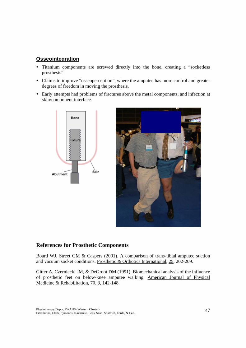
Osseointegration Titanium components are screwed directly into the bone, creating a “socketless
prosthesis”.
Claims to improve “osseoperception”, where the amputee has more control and greater degrees of freedom in moving the prosthesis.
Early attempts had problems of fractures above the metal components, and infection at skin/component interface.
References for Prosthetic Components
Board WJ, Street GM & Caspers (2001). A comparison of trans-tibial amputee suction and vacuum socket conditions. Prosthetic & Orthotics International, 25, 202-209.
Gitter A, Czerniecki JM, & DeGroot DM (1991). Biomechanical analysis of the influence of prosthetic feet on below-knee amputee walking. American Journal of Physical Medicine & Rehabilitation, 70, 3, 142-148.
Physiotherapy Depts, SWAHS (Western Cluster) Fitzsmions, Clark, Symonds, Navarrete, Lees, Saad, Shatford, Forde, & Lee. 48
Johansson JL, Sherril DM, Riley PO, Bonato P, Herr H (2005). A clinical comparison of variable-damping and mechanically passive prosthetic knee devices. American Journal of Physical Medicine and Rehabilitation, 84, 8, 563-575.
Lehmann JF, Price R, Boswell-Bessette S, Dralle A, & Questad K (1993). Comprehensive analysis of dynamic elastic response feet: Seattle Ankle/Lite Foot versus SACH foot. Archives of Physical Medicine & Rehabilitation, 74, 853-861.
Macfarlane PA, Nielson DH, Shurr DG, & Meier K (). Gait comparisons for below-knee amputees using a Flex-Foot versus a conventional prosthetic foot. Journal of Prosthetics & Orthotics, 3, 4, 150-161.
Murray MP, Mollinger LA, Sepic SB, Gardner GM & Linder RT (1983). Gait Patterns in Above-Knee Amputee Patients: Hydraulic Swing Control vs Constant Friction Knee Components. Archives of Physical Medicine & Rehabilitation, 64, 339-345.
Powers CM, Torburn L, Perry J, Ayyappa E (1994). Influence of Prosthetic foot design on Sound limb loading in adults with unilateral below-knee amputations. Archives of Physical Medicine & Rehabilitation, 75, 825-829.
Schmalz T, Blumentritt S, & Jarasch R (2002). A Comparison of Different prosthetic Knee Joints During Step Over Step Stair Descent. Orthopadie-Technik, 7, 586-592.
Snyder RD, Powers CM, Fontaine C, & Perry J (1995). The Effect of Five Prosthetic Feet on the gait and Loading of the Sound Limb in Dysvascular Below-Knee Amputees. Journal of Rehabilitation Research and Development, 32, 4, 309-315.
www.ottobock.com
www.ossur.com
www.college-park.com
www.freedom-innovations.com
Physiotherapy Depts, SWAHS (Western Cluster) Fitzsmions, Clark, Symonds, Navarrete, Lees, Saad, Shatford, Forde, & Lee. 49
Protocol for Making a Below Knee Temporary Prosthesis A step-by-step guide for the manufacturing of a temporary prosthesis is described below. Exact casting procedures may differ between therapists based on materials available and personal preferences, but the basic principles should be adhered to. The socket is made based on 2 important concepts:
• Total Contact – aims to distribute the forces over as large an area as possible to decrease the pressure to a tolerable level. Total contact also prevents development of dependent oedema or suction effects on the stump, which can lead to wound and skin problems such as verrucous hyperplasia. Therefore the total surface of the stump is utilised.
• Selective Loading: o Bony crests/prominences, scars, head of fibula, hamstring insertions and
the tibial crest do NOT tolerate pressure o Large masses of soft tissue or large smooth bony surfaces, tibial flares,
gastrocs, tibialis anterior muscle group and patellar tendon DO tolerate pressure.
o The socket is therefore contoured to selectively relieve pressure over the non-tolerant areas and load pressure over the tolerant areas.
The socket designed based on these principles will stabilise the bony remnant of the stump, and allows the amputee to translate control of the stump into control of the prosthesis. It will also reduce the risk of complications and stump breakdown due to friction or compression.
Biomechanics to Consider:
• Patellar Tendon Shelf is the rounded horizontal prominence on the inside of the socket. It is moulded on the middle of the patellar tendon and aims to act as a weight bearing surface, as well act as act as an identifiable landmark to enable ease of donning prosthesis correctly.
• Tibial flares should be moulded to distribute forces over a larger area and enhances relief over the tibial crest.
• Posteriorly the socket is contoured inwards over the lower part of the popliteal fossa. This pushes the stump forward onto weight bearing areas and helps to improve proximal stability of the stump within the socket.
This contouring results in a somewhat triangular shape which resists rotation of the stump within the socket.
Physiotherapy Depts, SWAHS (Western Cluster) Fitzsmions, Clark, Symonds, Navarrete, Lees, Saad, Shatford, Forde, & Lee. 50
Step by step guide
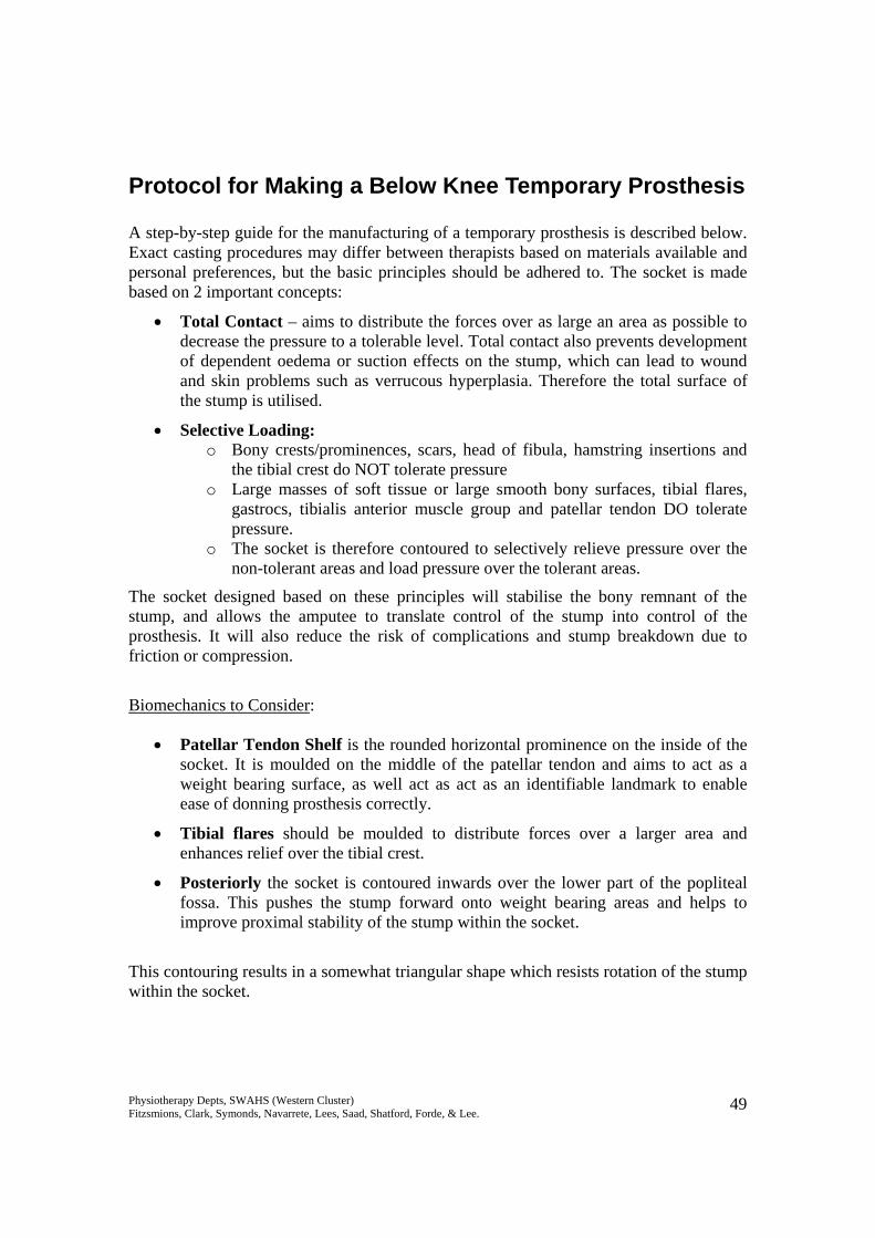
Pre-Casting 1. Inspect stump for bony areas, open wounds and soft tissue/scar adhesions and address
appropriately
2. Assess hip and knee joints – a combined contracture of up to 35º flexion can be accommodated for in the prosthesis.
3. Consider that exercise tolerance, UL strength, LL strength is adequate, and pain or sensitivity will not inhibit wearing of the prosthesis.
Casting
Equipment Required
• Stockinette / tubifast • 1 x 10cm elastic POP • 1-2 x 10cm POP • 10mm adhesive felt • 10mm adhesive foam (reston) • 3mm adhesive polycushion • Cling wrap • Scissors • Stump sock • Supracondylar cuff • Water • Gloves
Physiotherapy Depts, SWAHS (Western Cluster) Fitzsmions, Clark, Symonds, Navarrete, Lees, Saad, Shatford, Forde, & Lee. 51
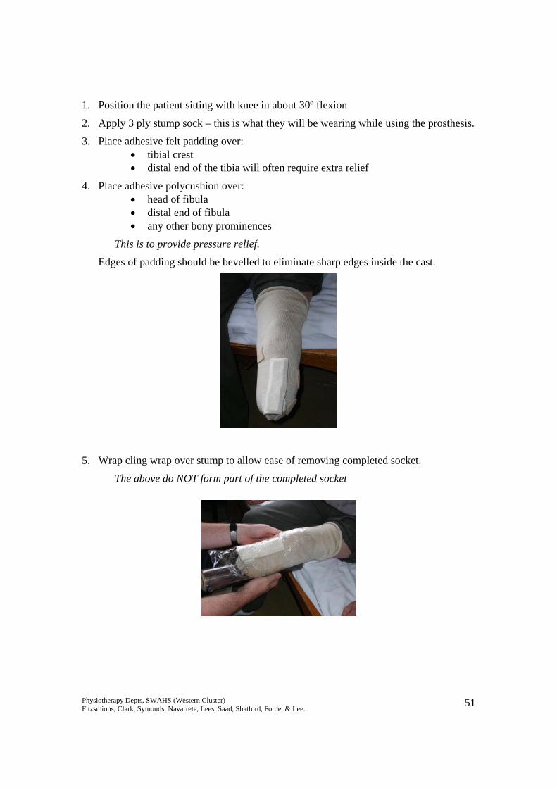
1. Position the patient sitting with knee in about 30º flexion
2. Apply 3 ply stump sock – this is what they will be wearing while using the prosthesis.
3. Place adhesive felt padding over: • tibial crest • distal end of the tibia will often require extra relief
4. Place adhesive polycushion over: • head of fibula • distal end of fibula • any other bony prominences
This is to provide pressure relief.
Edges of padding should be bevelled to eliminate sharp edges inside the cast.
5. Wrap cling wrap over stump to allow ease of removing completed socket.
The above do NOT form part of the completed socket
Physiotherapy Depts, SWAHS (Western Cluster) Fitzsmions, Clark, Symonds, Navarrete, Lees, Saad, Shatford, Forde, & Lee. 52
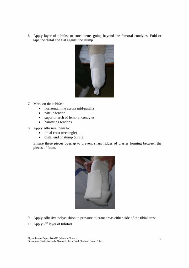
6. Apply layer of tubifast or stockinette, going beyond the femoral condyles. Fold or tape the distal end flat against the stump.
7. Mark on the tubifast: • horizontal line across mid-patella • patella tendon • superior arch of femoral condyles • hamstring tendons
8. Apply adhesive foam to: • tibial crest (rectangle) • distal end of stump (circle)
Ensure these pieces overlap to prevent sharp ridges of plaster forming between the pieces of foam.
9. Apply adhesive polycushion to pressure tolerant areas either side of the tibial crest.
10. Apply 2nd layer of tubifast
Physiotherapy Depts, SWAHS (Western Cluster) Fitzsmions, Clark, Symonds, Navarrete, Lees, Saad, Shatford, Forde, & Lee. 53
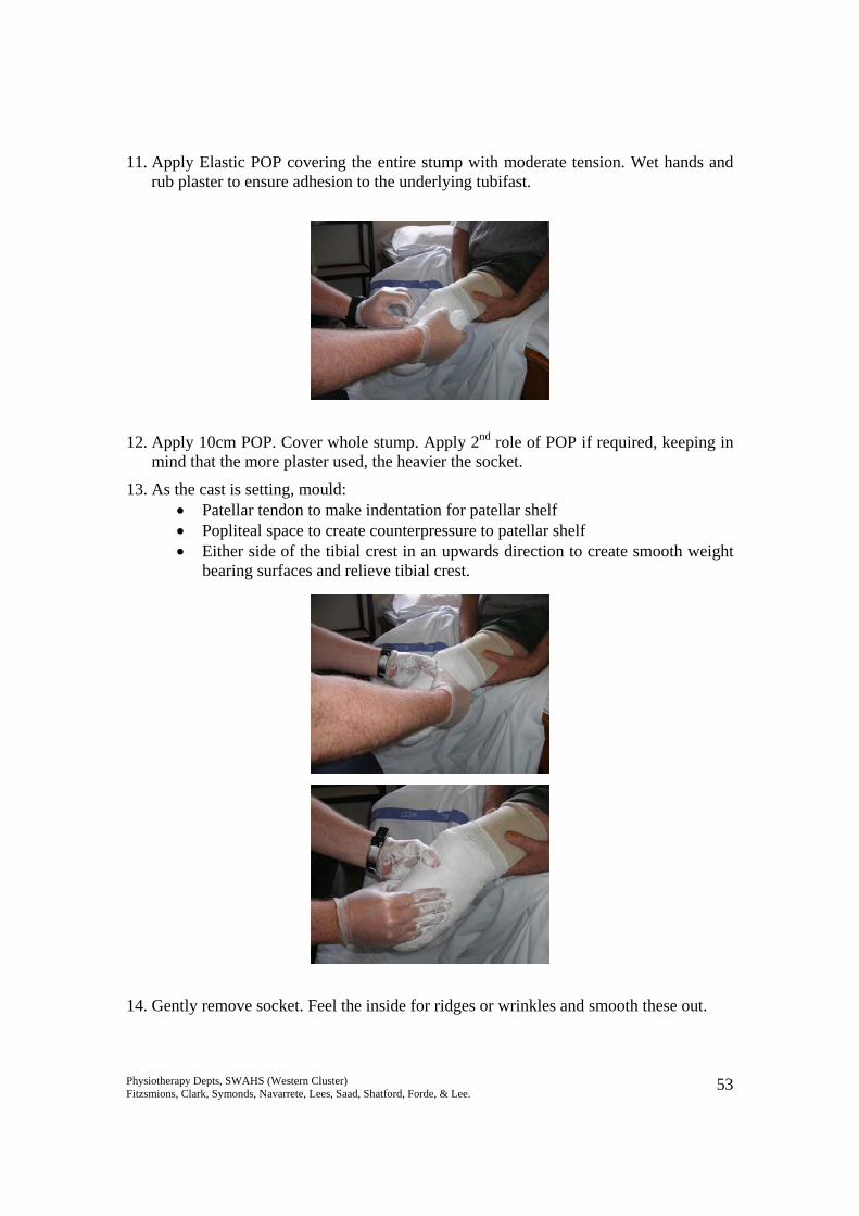
11. Apply Elastic POP covering the entire stump with moderate tension. Wet hands and rub plaster to ensure adhesion to the underlying tubifast.
12. Apply 10cm POP. Cover whole stump. Apply 2nd role of POP if required, keeping in mind that the more plaster used, the heavier the socket.
13. As the cast is setting, mould: • Patellar tendon to make indentation for patellar shelf • Popliteal space to create counterpressure to patellar shelf • Either side of the tibial crest in an upwards direction to create smooth weight
bearing surfaces and relieve tibial crest.
14. Gently remove socket. Feel the inside for ridges or wrinkles and smooth these out.
Physiotherapy Depts, SWAHS (Western Cluster) Fitzsmions, Clark, Symonds, Navarrete, Lees, Saad, Shatford, Forde, & Lee. 54
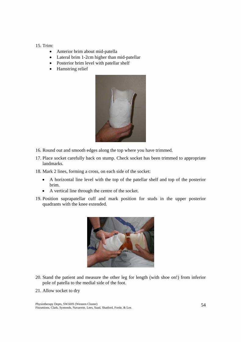
15. Trim: • Anterior brim about mid-patella • Lateral brim 1-2cm higher than mid-patellar • Posterior brim level with patellar shelf • Hamstring relief
16. Round out and smooth edges along the top where you have trimmed.
17. Place socket carefully back on stump. Check socket has been trimmed to appropriate landmarks.
18. Mark 2 lines, forming a cross, on each side of the socket:
• A horizontal line level with the top of the patellar shelf and top of the posterior brim.
• A vertical line through the centre of the socket.
19. Position suprapatellar cuff and mark position for studs in the upper posterior quadrants with the knee extended.
20. Stand the patient and measure the other leg for length (with shoe on!) from inferior pole of patella to the medial side of the foot.
21. Allow socket to dry
Physiotherapy Depts, SWAHS (Western Cluster) Fitzsmions, Clark, Symonds, Navarrete, Lees, Saad, Shatford, Forde, & Lee. 55
Mounting the Socket in the Basket Equipment Required
• Alignment Jig • Basket with 5 or 6 wire ribs and base plate • Allen keys • Plumb Bob • 1 x 10cm POP • 1 x 5cm POP • 7.5cm fibreglass plaster • Plaster scissors • Bending irons • 2 Brady studs for supracondylar strap • Paper towel • Rubber bands
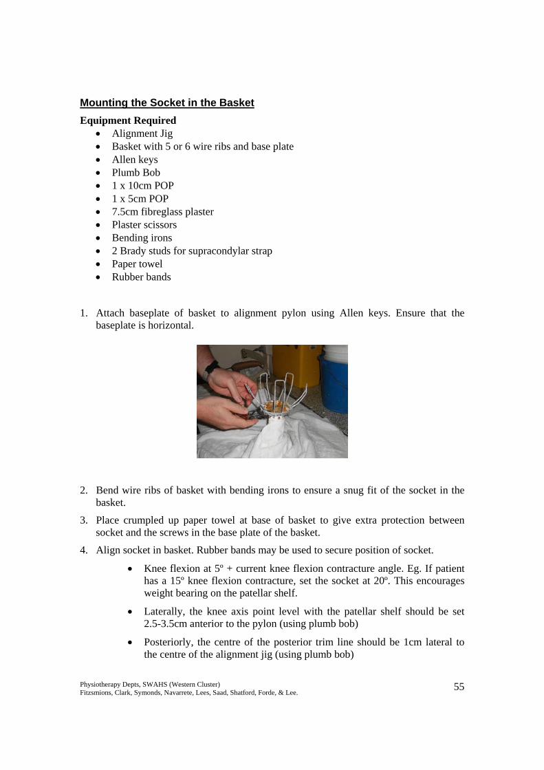
1. Attach baseplate of basket to alignment pylon using Allen keys. Ensure that the baseplate is horizontal.
2. Bend wire ribs of basket with bending irons to ensure a snug fit of the socket in the basket.
3. Place crumpled up paper towel at base of basket to give extra protection between socket and the screws in the base plate of the basket.
4. Align socket in basket. Rubber bands may be used to secure position of socket.
• Knee flexion at 5º + current knee flexion contracture angle. Eg. If patient has a 15º knee flexion contracture, set the socket at 20º. This encourages weight bearing on the patellar shelf.
• Laterally, the knee axis point level with the patellar shelf should be set 2.5-3.5cm anterior to the pylon (using plumb bob)
• Posteriorly, the centre of the posterior trim line should be 1cm lateral to the centre of the alignment jig (using plumb bob)
Physiotherapy Depts, SWAHS (Western Cluster) Fitzsmions, Clark, Symonds, Navarrete, Lees, Saad, Shatford, Forde, & Lee. 56
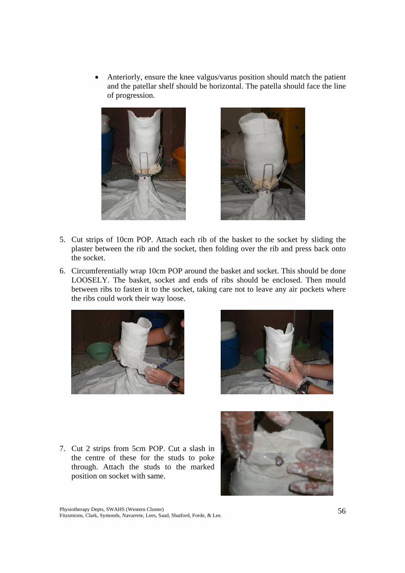
• Anteriorly, ensure the knee valgus/varus position should match the patient and the patellar shelf should be horizontal. The patella should face the line of progression.
5. Cut strips of 10cm POP. Attach each rib of the basket to the socket by sliding the plaster between the rib and the socket, then folding over the rib and press back onto the socket.
6. Circumferentially wrap 10cm POP around the basket and socket. This should be done LOOSELY. The basket, socket and ends of ribs should be enclosed. Then mould between ribs to fasten it to the socket, taking care not to leave any air pockets where the ribs could work their way loose.
7. Cut 2 strips from 5cm POP. Cut a slash in the centre of these for the studs to poke through. Attach the studs to the marked position on socket with same.
Physiotherapy Depts, SWAHS (Western Cluster) Fitzsmions, Clark, Symonds, Navarrete, Lees, Saad, Shatford, Forde, & Lee. 57
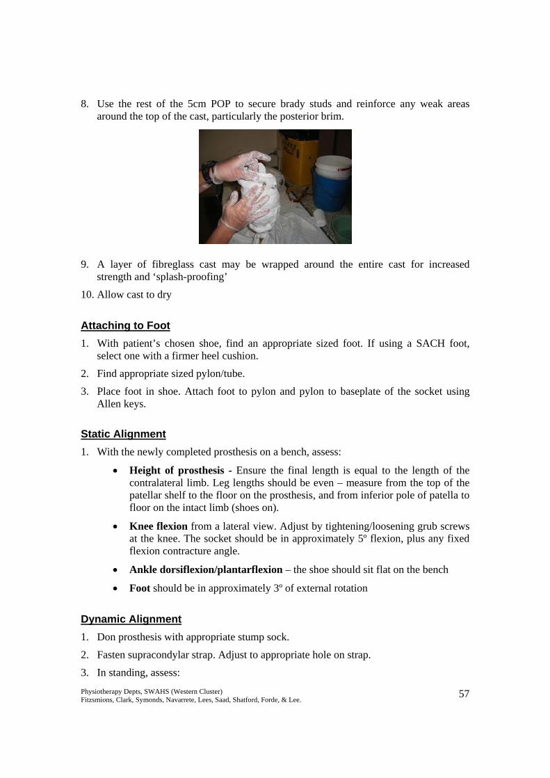
8. Use the rest of the 5cm POP to secure brady studs and reinforce any weak areas around the top of the cast, particularly the posterior brim.
9. A layer of fibreglass cast may be wrapped around the entire cast for increased strength and ‘splash-proofing’
10. Allow cast to dry
Attaching to Foot 1. With patient’s chosen shoe, find an appropriate sized foot. If using a SACH foot,
select one with a firmer heel cushion.
2. Find appropriate sized pylon/tube.
3. Place foot in shoe. Attach foot to pylon and pylon to baseplate of the socket using Allen keys.
Static Alignment 1. With the newly completed prosthesis on a bench, assess:
• Height of prosthesis - Ensure the final length is equal to the length of the contralateral limb. Leg lengths should be even – measure from the top of the patellar shelf to the floor on the prosthesis, and from inferior pole of patella to floor on the intact limb (shoes on).
• Knee flexion from a lateral view. Adjust by tightening/loosening grub screws at the knee. The socket should be in approximately 5º flexion, plus any fixed flexion contracture angle.
• Ankle dorsiflexion/plantarflexion – the shoe should sit flat on the bench
• Foot should be in approximately 3º of external rotation
Dynamic Alignment 1. Don prosthesis with appropriate stump sock.
2. Fasten supracondylar strap. Adjust to appropriate hole on strap.
3. In standing, assess:
Physiotherapy Depts, SWAHS (Western Cluster) Fitzsmions, Clark, Symonds, Navarrete, Lees, Saad, Shatford, Forde, & Lee. 58
• Height of prosthesis, ensure the pelvis is horizontal at the iliac crests. Adjust by changing position of the pylon in the tube clamp adaptor or changing tubes if required.
• Weight bearing through heel and toe of the prosthetic leg from a lateral view. Ensure the knee and hip are extended. You should not be able to slide a piece of paper under the heel or toe. Adjust by tightening/loosening grub screws at the foot or below the socket as appropriate.
• Anterior view / prosthesis in varus/valgus. With appropriate lateral pelvic shift, the pylon should be vertical, or even in a small amount of adduction. Adjust by tightening/loosening medial and lateral grub screws at the knee and/or foot.
4. Ask patient to shift weight onto the prosthetic side and question about any pressure or sore areas within the socket.
5. Ask the patient to lift the prosthesis, keeping their knee extended, and then put it back to the floor and weight bear on it. Observe any pistoning of the socket on the stump. A small amount of movement may be acceptable, but it should be minimised. Adjust the number of socks or position of the suprapatellar cuff as appropriate.
6. During walking, check that the push-off phase rolls of the correct aspect of the “big toe.” To adjust the tube clamp adaptor can be loosened and the tube rotated to correct the amount of foot external rotation.
7. Watch for any other gait deviations (see section on Below Knee Gait Analysis for assistance in determining prosthetic or patient causes for gait deviations).
8. Remove prosthesis and inspect stump. Ensure that reddened areas are only over pressure tolerant areas and weight bearing surfaces i.e. patellar shelf, medial tibial flare and anterolateral muscles. There should be no weight borne distally – a small ball of plasticine taped to the bottom of the stump can assist in determining this. If the plasticine is squashed, the patient is likely to be end bearing and the socket too loose.
9. Smooth out any plaster wrinkles inside socket using file, plaster saw or bending iron. Adjust patellar shelf if required, if too prominent, either side of the shelf can be padded to reduce the pressure. If the patellar shelf is insufficient, it can be padded to enlarge.
10. Commence prosthetic training, remembering to monitor the stump’s response to pressure and adjust alignment and number of layers of socks as required. Padding can also be added selectively to assist in ensuring the socket still fits as the stump volume changes.
Physiotherapy Depts, SWAHS (Western Cluster) Fitzsmions, Clark, Symonds, Navarrete, Lees, Saad, Shatford, Forde, & Lee. 59
Protocol for Making an Above Knee Temporary Prosthesis A step-by-step guide for the manufacturing of a temporary prosthesis is described below. Exact casting procedures may differ between therapists based on materials available and personal preferences, but the basic principles should be adhered to. The socket is made based on 2 important concepts:
• Total Contact – aims to distribute the forces over as large an area as possible to decrease the pressure to a tolerable level. Total contact also prevents development of dependent oedema or suction effects on the stump, which can lead to wound and skin problems such as verrucous hyperplasia. Therefore the total surface of the stump is utilised.
• Selective Loading: o Bony prominences such as distal end of femoral remnant or the pubic
ramus, do NOT tolerate pressure o Large masses of soft tissue or large bony surfaces, such as the ischial
tuberosity and lateral / posterior stump, DO tolerate pressure. o The socket is therefore contoured to selectively relieve pressure over the
non-tolerant areas and load pressure over the tolerant areas.
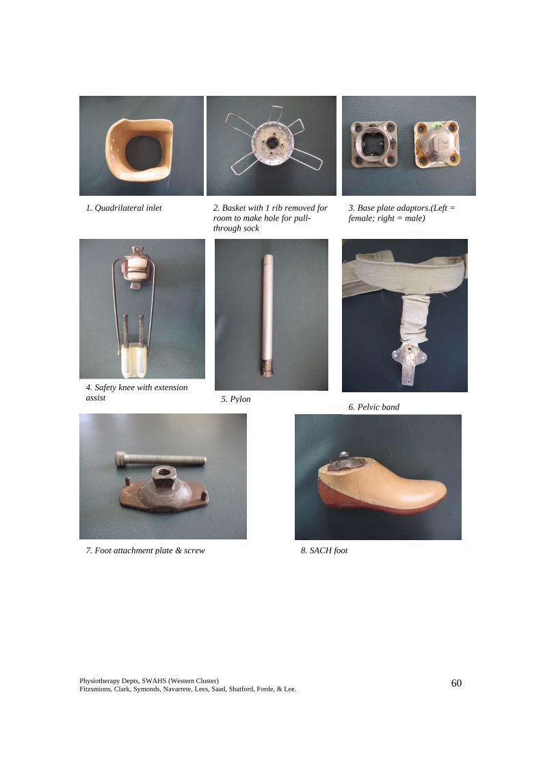
The socket designed based on these principles will stabilise the bony remnant of the stump, and allows the amputee to translate control of the stump into control of the prosthesis. It should be noted that it is difficult to stabilise the femoral remnant in its correct anatomical alignment, but every effort should be made to maintain an adducted position in order to maintain mechanical advantage of the hip abductors. Equipment needed Components for prosthesis needed: Goniometer 1. Quadrilateral inlet Tubifast / tubinette 2. Basket (6 rib) Felt/luxofoam/reston/padding materials 3. Base plate adaptor +/- rotator Cling/glad wrap 4. Knee joint (safety or lock) Scissors 5. Extension assist spring mechanism 1 x 10-15cm Elastik POP bandage 6. Pylon 1-2 x 10cm POP bandage 7. Foot (SACH or modular multiaxial) Bowl of water 8. Pelvic band Allen Keys 9. The patient’s shoe
Physiotherapy Depts, SWAHS (Western Cluster) Fitzsmions, Clark, Symonds, Navarrete, Lees, Saad, Shatford, Forde, & Lee. 60
Pic 1.QUAD INLET
1. Quadrilateral inlet 2. Basket with 1 rib removed for room to make hole for pull-through sock
3. Base plate adaptors.(Left = female; right = male)
4. Safety knee with extension assist 5. Pylon
8. SACH foot7. Foot attachment plate & screw
6. Pelvic band
Physiotherapy Depts, SWAHS (Western Cluster) Fitzsmions, Clark, Symonds, Navarrete, Lees, Saad, Shatford, Forde, & Lee. 61
Step by Step Guide
1. Inspect stump for localised tender areas, hard nodules, adhesions or scarring, or bony areas on the femoral remnant.
2. Make note of any hip flexion contractures (use Thomas test), adductor rolls (the flabby bit in groin area).
3. Measure the circumference of the upper most thigh (around groin) for the correct sizing of the quadrilateral inlet required.
Making of the socket
1. Apply first layer of tubifast (patient can start off in sitting)
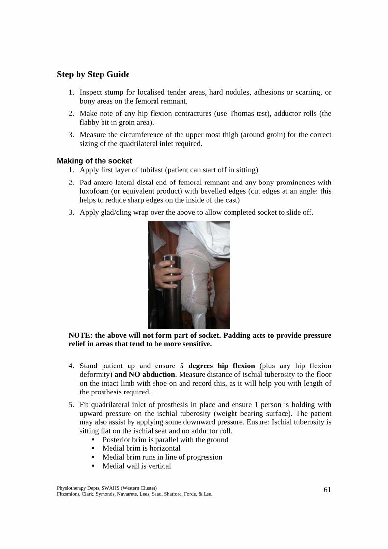
2. Pad antero-lateral distal end of femoral remnant and any bony prominences with luxofoam (or equivalent product) with bevelled edges (cut edges at an angle: this helps to reduce sharp edges on the inside of the cast)
3. Apply glad/cling wrap over the above to allow completed socket to slide off. NOTE: the above will not form part of socket. Padding acts to provide pressure relief in areas that tend to be more sensitive. 4. Stand patient up and ensure 5 degrees hip flexion (plus any hip flexion
deformity) and NO abduction. Measure distance of ischial tuberosity to the floor on the intact limb with shoe on and record this, as it will help you with length of the prosthesis required.
5. Fit quadrilateral inlet of prosthesis in place and ensure 1 person is holding with upward pressure on the ischial tuberosity (weight bearing surface). The patient may also assist by applying some downward pressure. Ensure: Ischial tuberosity is sitting flat on the ischial seat and no adductor roll.
Posterior brim is parallel with the ground Medial brim is horizontal Medial brim runs in line of progression Medial wall is vertical
Physiotherapy Depts, SWAHS (Western Cluster) Fitzsmions, Clark, Symonds, Navarrete, Lees, Saad, Shatford, Forde, & Lee. 62
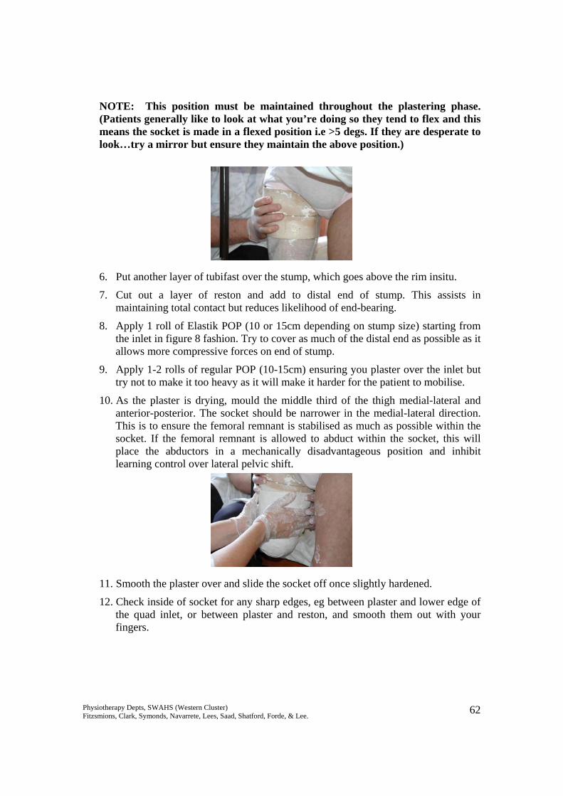
NOTE: This position must be maintained throughout the plastering phase. (Patients generally like to look at what you’re doing so they tend to flex and this means the socket is made in a flexed position i.e >5 degs. If they are desperate to look…try a mirror but ensure they maintain the above position.) 6. Put another layer of tubifast over the stump, which goes above the rim insitu.
7. Cut out a layer of reston and add to distal end of stump. This assists in maintaining total contact but reduces likelihood of end-bearing.
8. Apply 1 roll of Elastik POP (10 or 15cm depending on stump size) starting from the inlet in figure 8 fashion. Try to cover as much of the distal end as possible as it allows more compressive forces on end of stump.
9. Apply 1-2 rolls of regular POP (10-15cm) ensuring you plaster over the inlet but try not to make it too heavy as it will make it harder for the patient to mobilise.
10. As the plaster is drying, mould the middle third of the thigh medial-lateral and anterior-posterior. The socket should be narrower in the medial-lateral direction. This is to ensure the femoral remnant is stabilised as much as possible within the socket. If the femoral remnant is allowed to abduct within the socket, this will place the abductors in a mechanically disadvantageous position and inhibit learning control over lateral pelvic shift.
11. Smooth the plaster over and slide the socket off once slightly hardened.
12. Check inside of socket for any sharp edges, eg between plaster and lower edge of the quad inlet, or between plaster and reston, and smooth them out with your fingers.
Physiotherapy Depts, SWAHS (Western Cluster) Fitzsmions, Clark, Symonds, Navarrete, Lees, Saad, Shatford, Forde, & Lee. 63
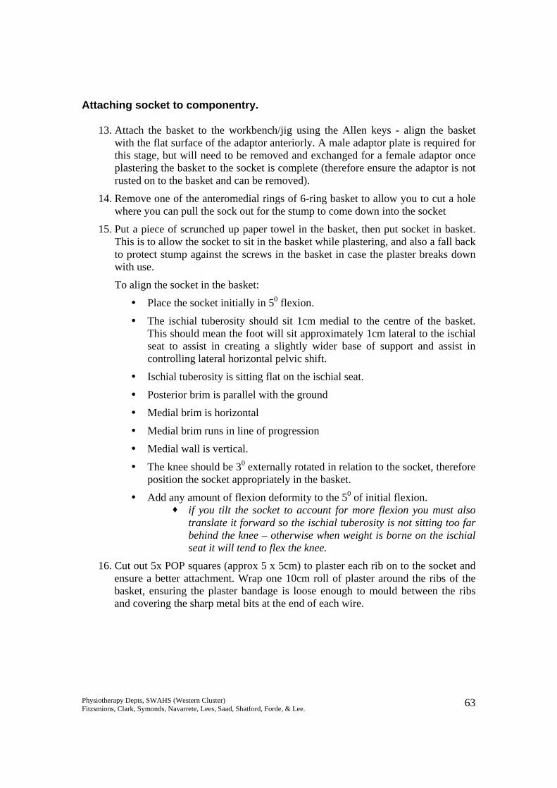
Attaching socket to componentry.
13. Attach the basket to the workbench/jig using the Allen keys - align the basket with the flat surface of the adaptor anteriorly. A male adaptor plate is required for this stage, but will need to be removed and exchanged for a female adaptor once plastering the basket to the socket is complete (therefore ensure the adaptor is not rusted on to the basket and can be removed).
14. Remove one of the anteromedial rings of 6-ring basket to allow you to cut a hole where you can pull the sock out for the stump to come down into the socket
15. Put a piece of scrunched up paper towel in the basket, then put socket in basket. This is to allow the socket to sit in the basket while plastering, and also a fall back to protect stump against the screws in the basket in case the plaster breaks down with use.
To align the socket in the basket:
Place the socket initially in 50 flexion.
The ischial tuberosity should sit 1cm medial to the centre of the basket. This should mean the foot will sit approximately 1cm lateral to the ischial seat to assist in creating a slightly wider base of support and assist in controlling lateral horizontal pelvic shift.
Ischial tuberosity is sitting flat on the ischial seat.
Posterior brim is parallel with the ground
Medial brim is horizontal
Medial brim runs in line of progression
Medial wall is vertical.
The knee should be 30 externally rotated in relation to the socket, therefore position the socket appropriately in the basket.
Add any amount of flexion deformity to the 50 of initial flexion. if you tilt the socket to account for more flexion you must also
translate it forward so the ischial tuberosity is not sitting too far behind the knee – otherwise when weight is borne on the ischial seat it will tend to flex the knee.
16. Cut out 5x POP squares (approx 5 x 5cm) to plaster each rib on to the socket and ensure a better attachment. Wrap one 10cm roll of plaster around the ribs of the basket, ensuring the plaster bandage is loose enough to mould between the ribs and covering the sharp metal bits at the end of each wire.
Physiotherapy Depts, SWAHS (Western Cluster) Fitzsmions, Clark, Symonds, Navarrete, Lees, Saad, Shatford, Forde, & Lee. 64
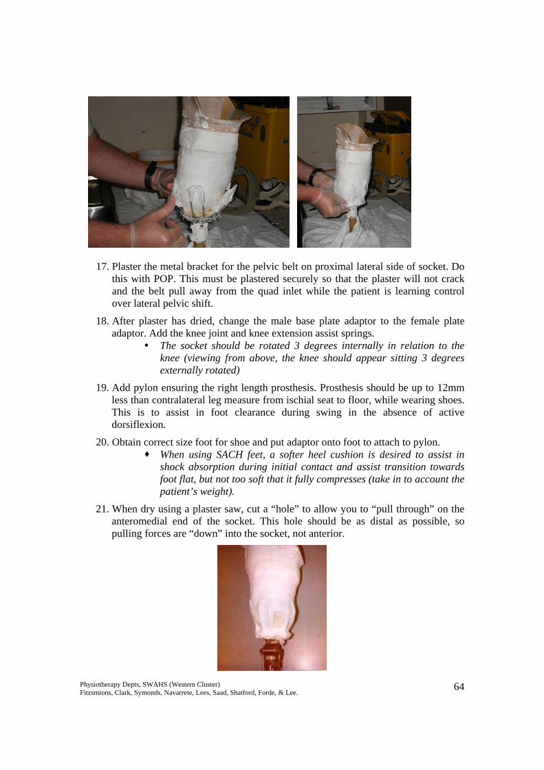
17. Plaster the metal bracket for the pelvic belt on proximal lateral side of socket. Do this with POP. This must be plastered securely so that the plaster will not crack and the belt pull away from the quad inlet while the patient is learning control over lateral pelvic shift.
18. After plaster has dried, change the male base plate adaptor to the female plate adaptor. Add the knee joint and knee extension assist springs.
The socket should be rotated 3 degrees internally in relation to the knee (viewing from above, the knee should appear sitting 3 degrees externally rotated)
19. Add pylon ensuring the right length prosthesis. Prosthesis should be up to 12mm less than contralateral leg measure from ischial seat to floor, while wearing shoes. This is to assist in foot clearance during swing in the absence of active dorsiflexion.
20. Obtain correct size foot for shoe and put adaptor onto foot to attach to pylon. When using SACH feet, a softer heel cushion is desired to assist in
shock absorption during initial contact and assist transition towards foot flat, but not too soft that it fully compresses (take in to account the patient’s weight).
21. When dry using a plaster saw, cut a “hole” to allow you to “pull through” on the anteromedial end of the socket. This hole should be as distal as possible, so pulling forces are “down” into the socket, not anterior.
Physiotherapy Depts, SWAHS (Western Cluster) Fitzsmions, Clark, Symonds, Navarrete, Lees, Saad, Shatford, Forde, & Lee. 65
Checking static alignment. 1. The TKA (trochanter knee ankle) line: runs up to 5-10mm in front of the knee
axis and just in front of heel of shoe. The further back the knee is the more stable it is during stance phase, BUT this means it may be more difficult to flex it through swing phase.
2. The socket should sit as per step 15 above.
3. The foot should be in slight dorsiflexion.
4. A well-aligned prosthesis will balance itself (with shoe on) without falling over. Check dynamic alignment on the patient:
1. Don the prosthesis with appropriate number of woollen socks, and use a pullthrough sock (length of tubinette) to pull all soft tissue into the quadrilateral socket.
2. Check that the amputee is sitting with their ischial tuberosity on the posterior shelf, and that there is no adductor roll.
3. Patient stands erect, both hips and knees extended (allowing the intact knee to flex will cover up incorrect height or poor control of lateral pelvic shift). There should be as much weight shifted to the prosthetic side as possible, so the patient is equal weight-bearing if possible.
4. Check alignment: Check height – compare levels of ASIS’s, PSIS’s, iliac crests or greater
trochanters bilaterally. The amputated side should be slightly lower. Foot should be flat on the floor. Knee / foot in 30 external rotation. With guidance to ensure correct alignment in weight bearing, the intact knee
should be extended, and the prosthetic pylon vertical, or in slight adduction, when viewed from the front.
The hinge part of the pelvic band should be close to the patient’s pelvis (Note that it is a pelvic band, not a waist band. The belt should be fixed around the pelvis to provide a firm hold, and minimise lateral movement of the socket in relation to the ischial tuberosity during lateral weight shift).
66
Gait Analysis and Training Below Knee Amputee Gait Analysis Normal Gait: Stance Hip extension throughout, from a position of flexion. Knee flexes ~150 initially, then extends, then flexes prior to toe-off. Pelvis moves laterally over the stance foot, around 4cm. Ankle plantarflexes from heelstrike to foot flat, then moves into dorsiflexion as tibia rotates over the foot. Finishes with rapid
plantarflexion at push-off. Swing Flexion of the hip, from a position of extension. Flexion of the knee. Lateral pelvic tilt downwards on the swing side. Rotation forward of the pelvis on the swing side. Extension of the knee and dorsiflexion prior to heelstrike.
Amputees generally exhibit: Increased gluteus maximus activity throughout entire stance on the amputated side, compensating for increased hamstrings activity. Increased hamstrings activity in early stance on the amputated side, to “pull” weight forward onto the prosthetic limb, or keep the
stump flexed within the socket to minimise anterior stump pressures. Hip extensor activity on the amputated side is present throughout stance, not just early stance. Decreased quads activity at weight acceptance on the amputated side, due to inability to maintain extension with a shortened (tibial)
lever arm, or an attempt to reduce anterior stump pressures as the stump tries to extend within the socket. Some concentric dorsiflexor activity in early stance on the intact side, “pulling” the tibia forwards, to compensate for lack of
propulsion / forward momentum created by the amputated side in late stance.
67
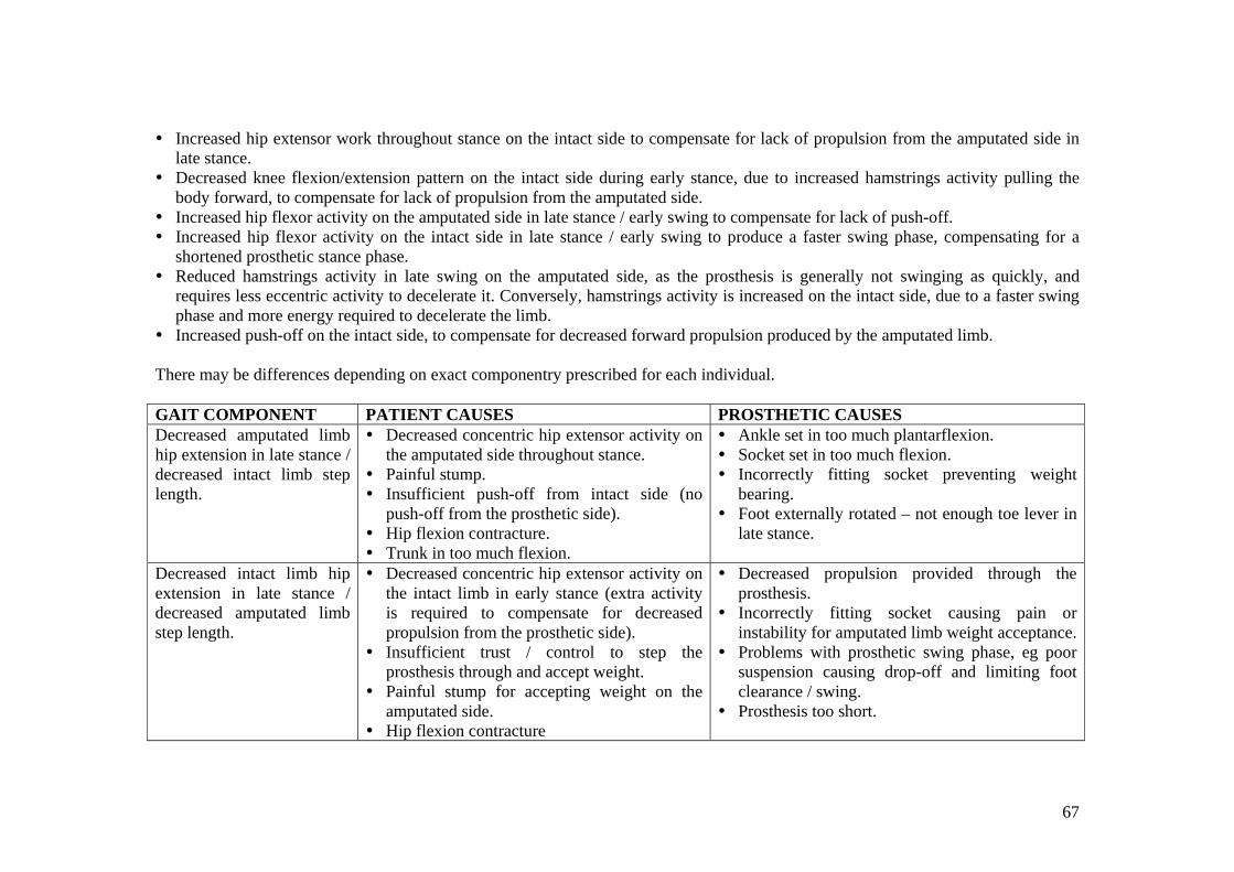
Increased hip extensor work throughout stance on the intact side to compensate for lack of propulsion from the amputated side in late stance.
Decreased knee flexion/extension pattern on the intact side during early stance, due to increased hamstrings activity pulling the body forward, to compensate for lack of propulsion from the amputated side.
Increased hip flexor activity on the amputated side in late stance / early swing to compensate for lack of push-off. Increased hip flexor activity on the intact side in late stance / early swing to produce a faster swing phase, compensating for a
shortened prosthetic stance phase. Reduced hamstrings activity in late swing on the amputated side, as the prosthesis is generally not swinging as quickly, and
requires less eccentric activity to decelerate it. Conversely, hamstrings activity is increased on the intact side, due to a faster swing phase and more energy required to decelerate the limb.
Increased push-off on the intact side, to compensate for decreased forward propulsion produced by the amputated limb. There may be differences depending on exact componentry prescribed for each individual. GAIT COMPONENT PATIENT CAUSES PROSTHETIC CAUSES Decreased amputated limb hip extension in late stance / decreased intact limb step length.
Decreased concentric hip extensor activity on the amputated side throughout stance.
Painful stump. Insufficient push-off from intact side (no
push-off from the prosthetic side). Hip flexion contracture. Trunk in too much flexion.
Ankle set in too much plantarflexion. Socket set in too much flexion. Incorrectly fitting socket preventing weight
bearing. Foot externally rotated – not enough toe lever in
late stance.
Decreased intact limb hip extension in late stance / decreased amputated limb step length.
Decreased concentric hip extensor activity on the intact limb in early stance (extra activity is required to compensate for decreased propulsion from the prosthetic side).
Insufficient trust / control to step the prosthesis through and accept weight.
Painful stump for accepting weight on the amputated side.
Hip flexion contracture
Decreased propulsion provided through the prosthesis.
Incorrectly fitting socket causing pain or instability for amputated limb weight acceptance.
Problems with prosthetic swing phase, eg poor suspension causing drop-off and limiting foot clearance / swing.
Prosthesis too short.
68
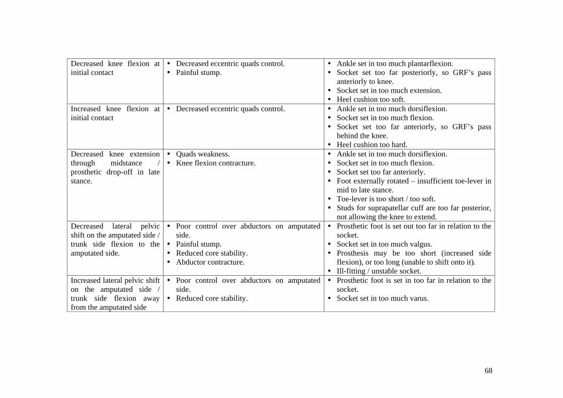
Decreased knee flexion at initial contact
Decreased eccentric quads control. Painful stump.
Ankle set in too much plantarflexion. Socket set too far posteriorly, so GRF’s pass
anteriorly to knee. Socket set in too much extension. Heel cushion too soft.
Increased knee flexion at initial contact
Decreased eccentric quads control. Ankle set in too much dorsiflexion. Socket set in too much flexion. Socket set too far anteriorly, so GRF’s pass
behind the knee. Heel cushion too hard.
Decreased knee extension through midstance / prosthetic drop-off in late stance.
Quads weakness. Knee flexion contracture.
Ankle set in too much dorsiflexion. Socket set in too much flexion. Socket set too far anteriorly. Foot externally rotated – insufficient toe-lever in
mid to late stance. Toe-lever is too short / too soft. Studs for suprapatellar cuff are too far posterior,
not allowing the knee to extend. Decreased lateral pelvic shift on the amputated side / trunk side flexion to the amputated side.
Poor control over abductors on amputated side.
Painful stump. Reduced core stability. Abductor contracture.
Prosthetic foot is set out too far in relation to the socket.
Socket set in too much valgus. Prosthesis may be too short (increased side
flexion), or too long (unable to shift onto it). Ill-fitting / unstable socket.
Increased lateral pelvic shift on the amputated side / trunk side flexion away from the amputated side
Poor control over abductors on amputated side.
Reduced core stability.
Prosthetic foot is set in too far in relation to the socket.
Socket set in too much varus.
69
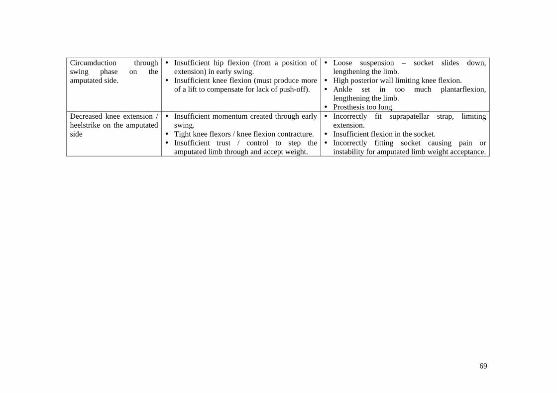
Circumduction through swing phase on the amputated side.
Insufficient hip flexion (from a position of extension) in early swing.
Insufficient knee flexion (must produce more of a lift to compensate for lack of push-off).
Loose suspension – socket slides down, lengthening the limb.
High posterior wall limiting knee flexion. Ankle set in too much plantarflexion,
lengthening the limb. Prosthesis too long.
Decreased knee extension / heelstrike on the amputated side
Insufficient momentum created through early swing.
Tight knee flexors / knee flexion contracture. Insufficient trust / control to step the
amputated limb through and accept weight.
Incorrectly fit suprapatellar strap, limiting extension.
Insufficient flexion in the socket. Incorrectly fitting socket causing pain or
instability for amputated limb weight acceptance.
70
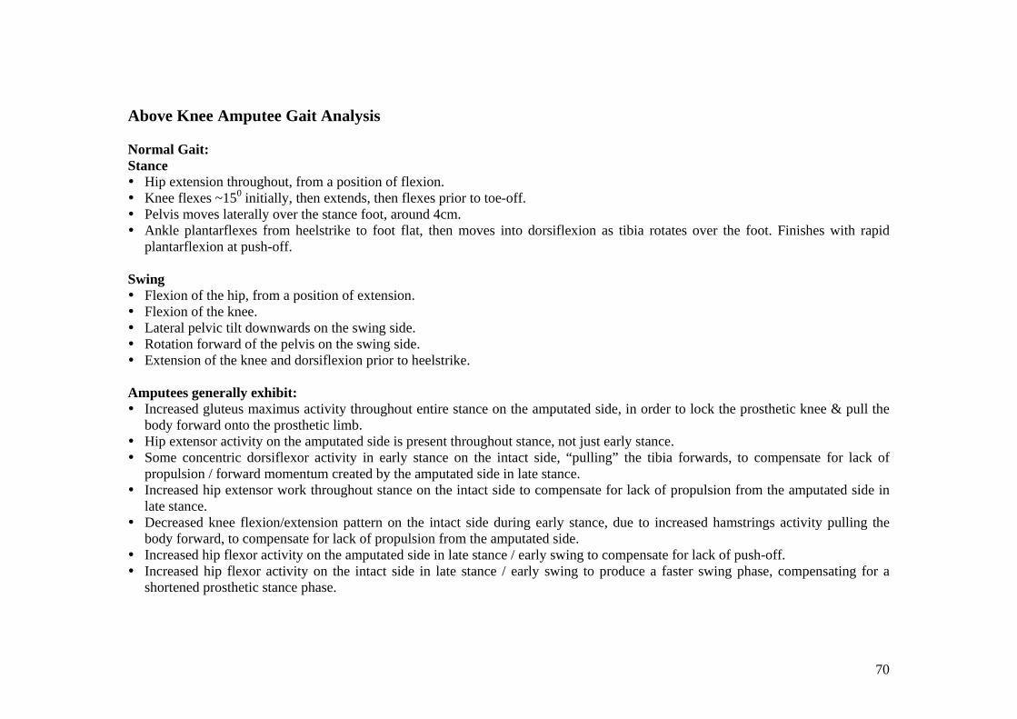
Above Knee Amputee Gait Analysis Normal Gait: Stance Hip extension throughout, from a position of flexion. Knee flexes ~150 initially, then extends, then flexes prior to toe-off. Pelvis moves laterally over the stance foot, around 4cm. Ankle plantarflexes from heelstrike to foot flat, then moves into dorsiflexion as tibia rotates over the foot. Finishes with rapid
plantarflexion at push-off. Swing Flexion of the hip, from a position of extension. Flexion of the knee. Lateral pelvic tilt downwards on the swing side. Rotation forward of the pelvis on the swing side. Extension of the knee and dorsiflexion prior to heelstrike.
Amputees generally exhibit: Increased gluteus maximus activity throughout entire stance on the amputated side, in order to lock the prosthetic knee & pull the
body forward onto the prosthetic limb. Hip extensor activity on the amputated side is present throughout stance, not just early stance. Some concentric dorsiflexor activity in early stance on the intact side, “pulling” the tibia forwards, to compensate for lack of
propulsion / forward momentum created by the amputated side in late stance. Increased hip extensor work throughout stance on the intact side to compensate for lack of propulsion from the amputated side in
late stance. Decreased knee flexion/extension pattern on the intact side during early stance, due to increased hamstrings activity pulling the
body forward, to compensate for lack of propulsion from the amputated side. Increased hip flexor activity on the amputated side in late stance / early swing to compensate for lack of push-off. Increased hip flexor activity on the intact side in late stance / early swing to produce a faster swing phase, compensating for a
shortened prosthetic stance phase.
71
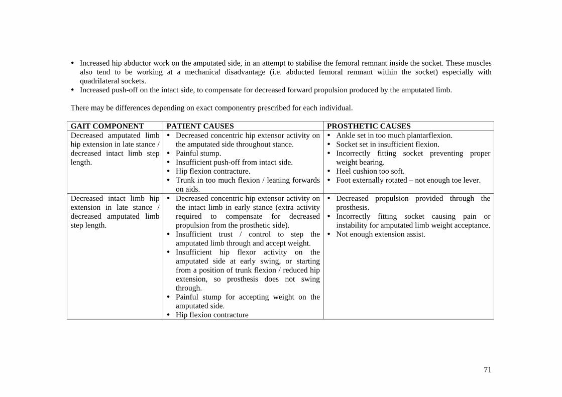
Increased hip abductor work on the amputated side, in an attempt to stabilise the femoral remnant inside the socket. These muscles also tend to be working at a mechanical disadvantage (i.e. abducted femoral remnant within the socket) especially with quadrilateral sockets.
Increased push-off on the intact side, to compensate for decreased forward propulsion produced by the amputated limb. There may be differences depending on exact componentry prescribed for each individual. GAIT COMPONENT PATIENT CAUSES PROSTHETIC CAUSES Decreased amputated limb hip extension in late stance / decreased intact limb step length.
Decreased concentric hip extensor activity on the amputated side throughout stance.
Painful stump. Insufficient push-off from intact side. Hip flexion contracture. Trunk in too much flexion / leaning forwards
on aids.
Ankle set in too much plantarflexion. Socket set in insufficient flexion. Incorrectly fitting socket preventing proper
weight bearing. Heel cushion too soft. Foot externally rotated – not enough toe lever.
Decreased intact limb hip extension in late stance / decreased amputated limb step length.
Decreased concentric hip extensor activity on the intact limb in early stance (extra activity required to compensate for decreased propulsion from the prosthetic side).
Insufficient trust / control to step the amputated limb through and accept weight.
Insufficient hip flexor activity on the amputated side at early swing, or starting from a position of trunk flexion / reduced hip extension, so prosthesis does not swing through.
Painful stump for accepting weight on the amputated side.
Hip flexion contracture
Decreased propulsion provided through the prosthesis.
Incorrectly fitting socket causing pain or instability for amputated limb weight acceptance.
Not enough extension assist.
72
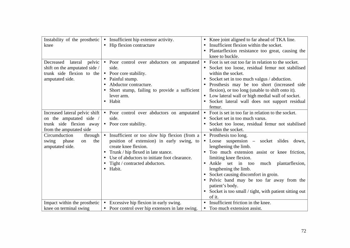
Instability of the prosthetic knee
Insufficient hip extensor activity. Hip flexion contracture
Knee joint aligned to far ahead of TKA line. Insufficient flexion within the socket. Plantarflexion resistance too great, causing the
knee to buckle. Decreased lateral pelvic shift on the amputated side / trunk side flexion to the amputated side.
Poor control over abductors on amputated side.
Poor core stability. Painful stump. Abductor contracture. Short stump, failing to provide a sufficient
lever arm. Habit
Foot is set out too far in relation to the socket. Socket too loose, residual femur not stabilised
within the socket. Socket set in too much valgus / abduction. Prosthesis may be too short (increased side
flexion), or too long (unable to shift onto it). Low lateral wall or high medial wall of socket. Socket lateral wall does not support residual
femur. Increased lateral pelvic shift on the amputated side / trunk side flexion away from the amputated side
Poor control over abductors on amputated side.
Poor core stability.
Foot is set in too far in relation to the socket. Socket set in too much varus. Socket too loose, residual femur not stabilised
within the socket. Circumduction through swing phase on the amputated side.
Insufficient or too slow hip flexion (from a position of extension) in early swing, to create knee flexion.
Trunk / hip flexed in late stance. Use of abductors to initiate foot clearance. Tight / contracted abductors. Habit.
Prosthesis too long. Loose suspension – socket slides down,
lengthening the limb. Too much extension assist or knee friction,
limiting knee flexion. Ankle set in too much plantarflexion,
lengthening the limb. Socket causing discomfort in groin. Pelvic band may be too far away from the
patient’s body. Socket is too small / tight, with patient sitting out
of it. Impact within the prosthetic knee on terminal swing
Excessive hip flexion in early swing. Poor control over hip extensors in late swing.
Insufficient friction in the knee. Too much extension assist.
73
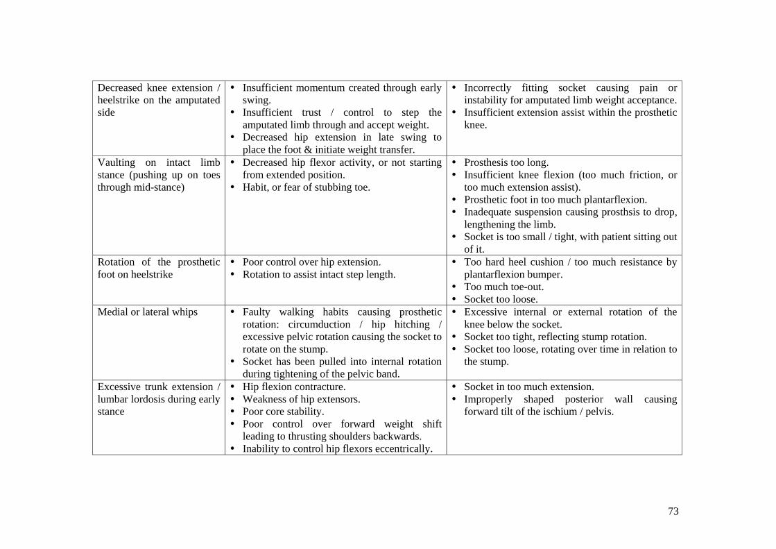
Decreased knee extension / heelstrike on the amputated side
Insufficient momentum created through early swing.
Insufficient trust / control to step the amputated limb through and accept weight.
Decreased hip extension in late swing to place the foot & initiate weight transfer.
Incorrectly fitting socket causing pain or instability for amputated limb weight acceptance.
Insufficient extension assist within the prosthetic knee.
Vaulting on intact limb stance (pushing up on toes through mid-stance)
Decreased hip flexor activity, or not starting from extended position.
Habit, or fear of stubbing toe.
Prosthesis too long. Insufficient knee flexion (too much friction, or
too much extension assist). Prosthetic foot in too much plantarflexion. Inadequate suspension causing prosthsis to drop,
lengthening the limb. Socket is too small / tight, with patient sitting out
of it. Rotation of the prosthetic foot on heelstrike
Poor control over hip extension. Rotation to assist intact step length.
Too hard heel cushion / too much resistance by plantarflexion bumper.
Too much toe-out. Socket too loose.
Medial or lateral whips Faulty walking habits causing prosthetic rotation: circumduction / hip hitching / excessive pelvic rotation causing the socket to rotate on the stump.
Socket has been pulled into internal rotation during tightening of the pelvic band.
Excessive internal or external rotation of the knee below the socket.
Socket too tight, reflecting stump rotation. Socket too loose, rotating over time in relation to
the stump.
Excessive trunk extension / lumbar lordosis during early stance
Hip flexion contracture. Weakness of hip extensors. Poor core stability. Poor control over forward weight shift
leading to thrusting shoulders backwards. Inability to control hip flexors eccentrically.
Socket in too much extension. Improperly shaped posterior wall causing
forward tilt of the ischium / pelvis.
74
Below Knee Amputee Gait on Stairs Normal Gait (McFadyen & Winter, 1988): Ascent: Weight Acceptance: body moves into position to ascend up. Initiated by contralateral plantarflexors. Involves strong concentric hip
& knee extensor activity. Pull-Up: body rises up the step; the most unstable position as involves single support while all three lower limb joints are in a
flexed position. Power generated mainly by vastus lateralis & soleus. Gluteus medius is active to keep the pelvis level. Forward Continuance: horizontal movement, as body shifts forward in preparation for striking the next step. Support moment
remains extensor throughout. Plantarflexors work strongly at the end of this phase to produce vertical thrust, lifting body weight as weight is accepted on the contralateral limb on the next step.
Foot Clearance: the foot lifts over the intermediate step. Involves concentric dorsiflexor & hamstrings activity. Requires up to 1200 of knee flexion.
Foot Placement: foot contacts the next step. Involves eccentric hamstrings activity to lower & place the foot, and preparatory actions by quads, glut medius & maximus,
Descent: Weight Acceptance: the foot contacts the step, usually with a toe strike. Energy is absorbed mainly through plantarflexors, but also
by quads. Forward Continuance: Body weight moves over the stance foot, mainly in a horizontal direction. Support moment remains
extensor, with movement controlled by eccentric plantarflexors. Controlled Lowering: Body weight is lowered to the next step for contralateral weight acceptance. Involves large amounts of
eccentric quads activity & soleus activity, with a burst of concentric soleus activity prior to toe-off to help relieve the extreme dorsiflexed position.
Leg Pull-through: Hip flexes concentrically. The knee also flexes, usually up to 1000. Foot Placement: reversal of flexion as leg extends in preparation for next weight acceptance. Hamstrings control the descent of the
lower leg, & there are preparatory actions in plantarflexors, gluteus medius & maximus, and quads preparing for weight acceptance.
75
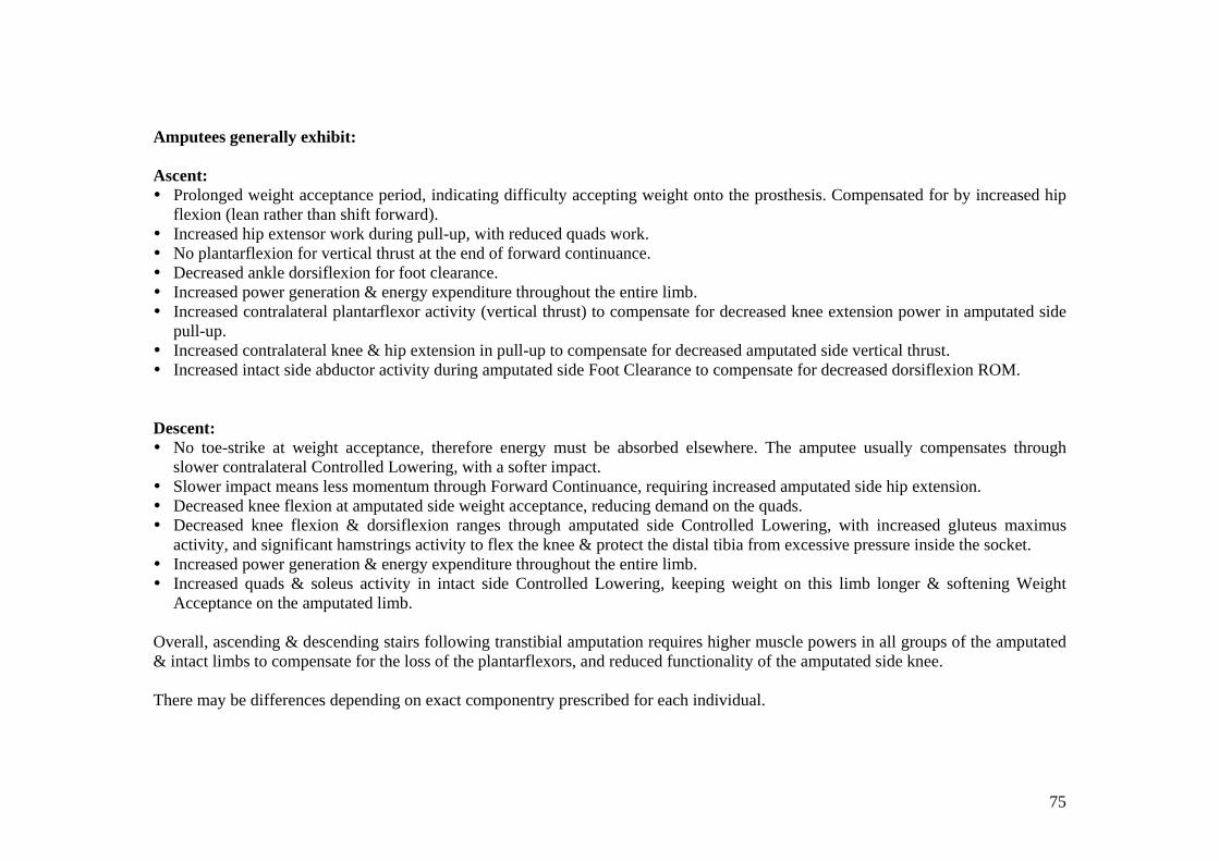
Amputees generally exhibit: Ascent: Prolonged weight acceptance period, indicating difficulty accepting weight onto the prosthesis. Compensated for by increased hip
flexion (lean rather than shift forward). Increased hip extensor work during pull-up, with reduced quads work. No plantarflexion for vertical thrust at the end of forward continuance. Decreased ankle dorsiflexion for foot clearance. Increased power generation & energy expenditure throughout the entire limb. Increased contralateral plantarflexor activity (vertical thrust) to compensate for decreased knee extension power in amputated side
pull-up. Increased contralateral knee & hip extension in pull-up to compensate for decreased amputated side vertical thrust. Increased intact side abductor activity during amputated side Foot Clearance to compensate for decreased dorsiflexion ROM.
Descent: No toe-strike at weight acceptance, therefore energy must be absorbed elsewhere. The amputee usually compensates through
slower contralateral Controlled Lowering, with a softer impact. Slower impact means less momentum through Forward Continuance, requiring increased amputated side hip extension. Decreased knee flexion at amputated side weight acceptance, reducing demand on the quads. Decreased knee flexion & dorsiflexion ranges through amputated side Controlled Lowering, with increased gluteus maximus
activity, and significant hamstrings activity to flex the knee & protect the distal tibia from excessive pressure inside the socket. Increased power generation & energy expenditure throughout the entire limb. Increased quads & soleus activity in intact side Controlled Lowering, keeping weight on this limb longer & softening Weight
Acceptance on the amputated limb. Overall, ascending & descending stairs following transtibial amputation requires higher muscle powers in all groups of the amputated & intact limbs to compensate for the loss of the plantarflexors, and reduced functionality of the amputated side knee. There may be differences depending on exact componentry prescribed for each individual.
76
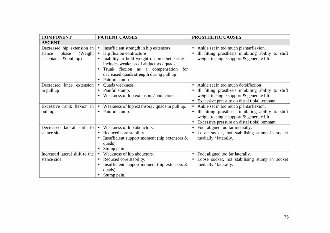
COMPONENT PATIENT CAUSES PROSTHETIC CAUSES ASCENT Decreased hip extension in stance phase (Weight acceptance & pull up)
Insufficient strength in hip extensors. Hip flexion contracture Inability to hold weight on prosthetic side –
includes weakness of abductors / quads Trunk flexion as a compensation for
decreased quads strength during pull up Painful stump
Ankle set in too much plantarflexion. Ill fitting prosthesis inhibiting ability to shift
weight to single support & generate lift.
Decreased knee extension in pull up
Quads weakness. Painful stump. Weakness of hip extensors / abductors
Ankle set in too much dorsiflexion Ill fitting prosthesis inhibiting ability to shift
weight to single support & generate lift. Excessive pressure on distal tibial remnant.
Excessive trunk flexion in pull up.
Weakness of hip extensors / quads in pull up. Painful stump.
Ankle set in too much plantarflexion. Ill fitting prosthesis inhibiting ability to shift
weight to single support & generate lift. Excessive pressure on distal tibial remnant.
Decreased lateral shift to stance side.
Weakness of hip abductors. Reduced core stability. Insufficient support moment (hip extensors &
quads). Stump pain
Foot aligned too far medially. Loose socket, not stabilising stump in socket
medially / laterally.
Increased lateral shift to the stance side.
Weakness of hip abductors. Reduced core stability. Insufficient support moment (hip extensors &
quads). Stump pain.
Foot aligned too far laterally. Loose socket, not stabilising stump in socket
medially / laterally.
77
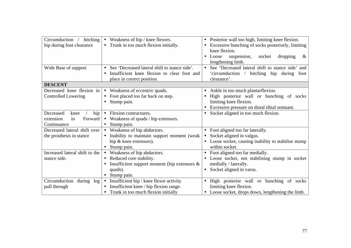
Circumduction / hitching hip during foot clearance
Weakness of hip / knee flexors. Trunk in too much flexion initially.
Posterior wall too high, limiting knee flexion. Excessive bunching of socks posteriorly, limiting
knee flexion. Loose suspension, socket dropping &
lengthening limb. Wide Base of support See ‘Decreased lateral shift to stance side’.
Insufficient knee flexion to clear foot and place in correct position.
See ‘Decreased lateral shift to stance side’ and ‘circumduction / hitching hip during foot clearance’.
DESCENT Decreased knee flexion in Controlled Lowering
Weakness of eccentric quads. Foot placed too far back on step. Stump pain.
Ankle in too much plantarflexion. High posterior wall or bunching of socks
limiting knee flexion. Excessive pressure on distal tibial remnant.
Decreased knee / hip extension in Forward Continuance
Flexion contractures. Weakness of quads / hip extensors. Stump pain.
Socket aligned in too much flexion.
Decreased lateral shift over the prosthesis in stance
Weakness of hip abductors. Inability to maintain support moment (weak
hip & knee extensors). Stump pain.
Foot aligned too far laterally. Socket aligned in valgus. Loose socket, causing inability to stabilise stump
within socket. Increased lateral shift to the stance side.
Weakness of hip abductors. Reduced core stability. Insufficient support moment (hip extensors &
quads). Stump pain.
Foot aligned too far medially. Loose socket, not stabilising stump in socket
medially / laterally. Socket aligned in varus.
Circumduction during leg pull through
Insufficient hip / knee flexor activity Insufficient knee / hip flexion range. Trunk in too much flexion initially
High posterior wall or bunching of socks limiting knee flexion.
Loose socket, drops down, lengthening the limb.
78
Gait Training Principles
A full list of training strategies is beyond the scope of this manual, as exact exercise prescription is dependent on assessment findings and client goals.
In general, training an amputee to walk with a prosthesis is guided by the following principles:
• Maintenance of full passive ROM / muscle length. o Full range is required to maintain the normal mechanical advantage of
muscle groups, and make use of motion-dependent / inertial /gravity-assisted movements.
o Full range is also required to assist in creating normal patterns and prevent secondary musculoskeletal disorders, such as overuse of certain muscles, back pain, etc.
• Education regarding correct fit of the prosthesis, and what to do when problems occur.
o The stump will vary in size during prosthetic training sessions, due to compression and effects of the muscle pump.
o Socks come in 1-ply, 3-ply, and 5-ply thicknesses. Vary the number and thicknesses of socks to maintain a secure, comfortable fit, with weight borne on the appropriate surfaces.
o Use a pull-through sock with AKA’s to ensure all proximal soft tissue is pulled into the socket, preventing formation of an adductor roll, and that the ischial tuberosity is sitting correctly on the quad-socket seat.
o Monitor the prosthesis for excessive pistoning / pumping, and vary socks or suspension appropriately.
o Regularly check the stump for pressure or friction areas, and integrity of the wound.
• Ability to balance on the prosthesis, and shift weight towards the prosthetic side with correct alignment & appropriate postural adjustments.
o Tolerance to bearing weight through the prosthesis usually needs to be built up over time.
o Training correct postural adjustments and weight shifting early on can reduce the reliance on hand support later on.
o Postural adjustments include preparatory muscle activity, which can improve safety and stability and speed of movement.
• Ability to activate the appropriate muscles / agonists through the required range, with the required strength, power, co-ordination & timing.
o This includes the residual and intact limbs. o The intact limb compensates for missing muscle groups in some
aspects of power generation & absorption during gait. o Training should also include speed of movement as close as possible to
what occurs during gait, eg speed of lateral pelvic shift during weight acceptance, speed of hip flexion for foot clearance in AKA’s.
o Timing is important, eg in AKA’s with safety knees hip extensor activity commences just prior to heelstrike and is continuous throughout stance phase.
79
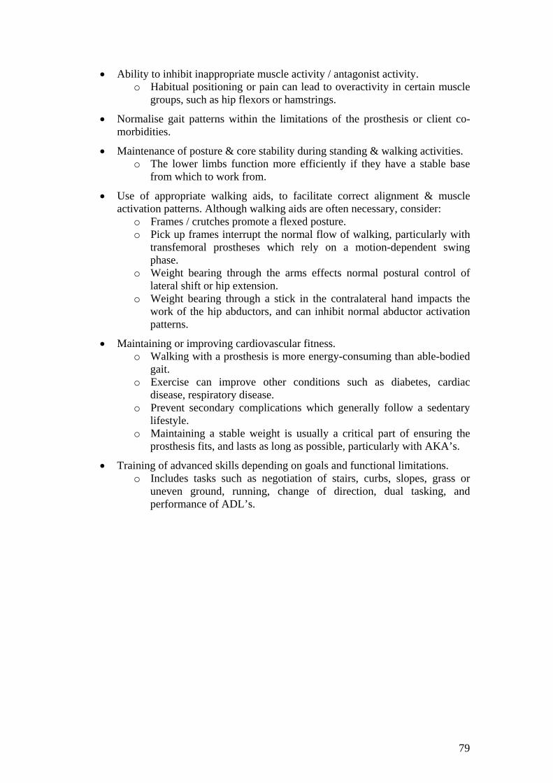
• Ability to inhibit inappropriate muscle activity / antagonist activity. o Habitual positioning or pain can lead to overactivity in certain muscle
groups, such as hip flexors or hamstrings.
• Normalise gait patterns within the limitations of the prosthesis or client co-morbidities.
• Maintenance of posture & core stability during standing & walking activities. o The lower limbs function more efficiently if they have a stable base
from which to work from.
• Use of appropriate walking aids, to facilitate correct alignment & muscle activation patterns. Although walking aids are often necessary, consider:
o Frames / crutches promote a flexed posture. o Pick up frames interrupt the normal flow of walking, particularly with
transfemoral prostheses which rely on a motion-dependent swing phase.
o Weight bearing through the arms effects normal postural control of lateral shift or hip extension.
o Weight bearing through a stick in the contralateral hand impacts the work of the hip abductors, and can inhibit normal abductor activation patterns.
• Maintaining or improving cardiovascular fitness. o Walking with a prosthesis is more energy-consuming than able-bodied
gait. o Exercise can improve other conditions such as diabetes, cardiac
disease, respiratory disease. o Prevent secondary complications which generally follow a sedentary
lifestyle. o Maintaining a stable weight is usually a critical part of ensuring the
prosthesis fits, and lasts as long as possible, particularly with AKA’s.
• Training of advanced skills depending on goals and functional limitations. o Includes tasks such as negotiation of stairs, curbs, slopes, grass or
uneven ground, running, change of direction, dual tasking, and performance of ADL’s.
80
References for Gait Andriacchi, T.P, Andersson, G.B.J, Fermier, R.W, Stern, D, & Galante, J.O. (1980). A Study of Lower Limb Mechanics during Stair-Climbing. Journal of Bone and Joint Surgery, 62A, 5, 749-757. Gottschalk FA & Stills M (1994). The biomechanics of trans-femoral amputation. Prosthetics & Orthotics International, 18, 12-17. Hurley, GRB, McKenney R, Robinson M, Zadravec, M & Pierrynowski MR (1990) The role of the contralateral limb in below-knee amputee gait. Prosthetics & Orthotics International, 14, 33-42. Jaegers SMHJ; Arendzen JH & DeJongh HJ (1995). Prosthetic gait of unilateral transfemoral amputees. Archives of Physical Medicine & Rehabilitation, 76, 736-743. Jaegers SMHJ; Arendzen JH & DeJongh HJ (1995). An electromyographic study of the hip muscles of transfemoral amputees in walking. Clinical Orthopaedics & Related Research, 328, 119-128. Jones, ME; Bashford, GM & Bliokas VV (2001). Weight-bearing, pain and walking velocity during primary transtibial amputee rehabilitation. Clinical Rehabilitation, 15, 172-176. Lemaire, ED; Fisher, FR; & Robertson DGE (1993) Gait patterns of elderly men with trans-tibial amputations. Prosthetics & Orthotics International, 17, 27-37. Livingston, L.A, Stevenson, J.M, & Olney, S.J. (1991). Stairclimbing kinematics on stairs of differing dimensions. Archives of Physical Medicine and Rehabilitation. 72, May, 398-402. Lyons, K., Perry, J, Gronley, J.K, Barnes, L, and Antonelli, D. (1983). Timing and relative intensity of hip extensor and abductor muscle action during level stair ambulation. Physical Therapy, 63, 10, 1597-1605. McFadyen, B.J, & Winter, D.A, (1988). An integrated biomechanical analysis of normal stair ascent and descent. Journal of Biomechanics. 21, 9, 733-744. Pinzur MS; Cox, W; Kaiser J; Morris T; Patwardhan A & Vrbos L (1995). The effect of prosthetic alignment on relative limb loading in persons with trans-tibial amputation: a preliminary report. Journal of Rehabilitation, Research & Development, 32, 4, 373-378. Powers, CM; Torburn, L; Perry, J & Ayyappa E (1994). Influence of prosthetic foot design on sound limb loading in adults with unilateral below-knee amputations. Archives of Physical Medicine & Rehabilitation, 75, 825-829. Powers, C.M, Boyd, L.A, Torburn, L, & Perry, J. (1997). Stair Ambulation in Persons with Transtibial Amputation: An Analysis of the Seattle Lightfoot. Journal of Rehabilitation research & Development, 34, 1, 9-18.
81
Rowe, P.J, Myles, C.M, Walker, C, & Nutton, R. (2000). Knee joint kinematics in gait and other functional activities measured using flexible electrogoniometry: how much knee motion is sufficient for normal daily life? Gait and Posture, 12, 2, 143-155. Sadeghi, H; Allard P; & Duhaime M (2001). Muscle power compensatory mechanisms in below-knee amputee gait. American Journal of Physical Medicine Rehabilitation, 80, 1, 25-32. Seroussi RE; Gitter A; Czerniecki JM & Weaver K (1996). Mechanical work adaptations of above-knee amputee ambulation. Archives of Physical Medicine & Rehabilitation, 77, 1209-1214. Smith AW (1990) A biomechanical analysis of amputee athlete gait. International Journal of Sport Biomechanics, 6, 262-282. Torburn, L, Schweiger G.P, Perry, J. & Powers, C.M. (1994). Below-Knee Amputee Gait in Stair Ambulation: a Comparison of Stride Characteristics Using Five Different Prosthetic Feet. Clinical Orthopaedics & Related Research, 303, 185-192. Waters RL, Mulroy S (1999). The energy expenditure of normal and pathological gait. Gait and Posture, 9, 207-231. Winter, DA (1983). Biomechanical motor patterns in normal walking. Journal of Motor Behaviour, 15, 4, 302-330. Winter DA & Sienko SE (1988). Biomechanics of below-knee amputee gait. Journal of Biomechanics, 21, 5, 361-367. Winter, D.A, Patla, A.E, Frank, J.S, & Walt, S.E. (1990). Biomechanical walking pattern changes in the fit and healthy elderly. Physical Therapy, 70, 6, 340-347. Yack, H.J, Nielson, D.H, & Shurr, D.G. (1999). Kinetic Patterns during Stair Ascent in Patients with Transtibial Amputations Using Three Different prostheses. Journal of Prosthetics & Orthotics, 11, 3, 57- Yu, B, Kienbacher, T, Growney, E.S, Johnson, M.E, & An, K.E. (1997). Reproducibility of the kinematics and kinetics of the lower extremity during normal stair climbing. Journal of Orthopaedic Research. 15, 3, 348-352. Zachazewski, J.E, Riley, P.O, & Krebs, D.E (1993). Biomechanical analysis of body mass transfer during stair ascent and descent of healthy subjects. Journal of Rehabilitation Research and Development, 30, 4, 412-422.
82
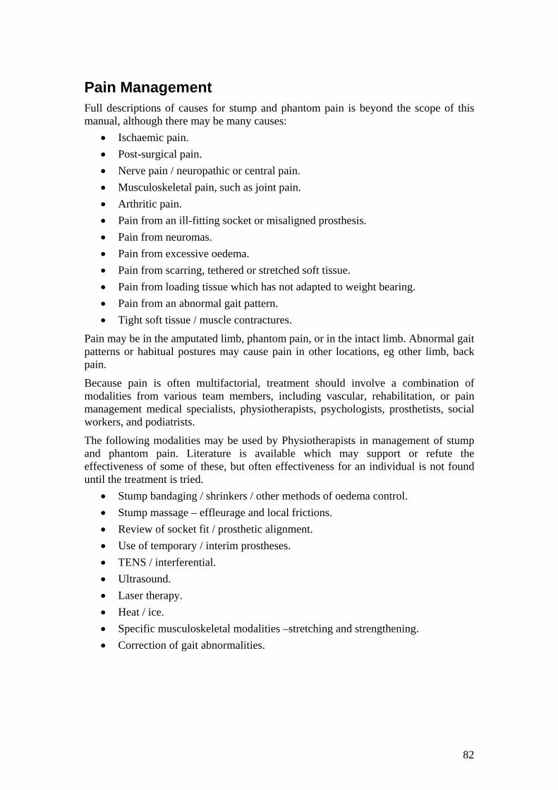
Pain Management Full descriptions of causes for stump and phantom pain is beyond the scope of this manual, although there may be many causes:
• Ischaemic pain. • Post-surgical pain. • Nerve pain / neuropathic or central pain. • Musculoskeletal pain, such as joint pain. • Arthritic pain. • Pain from an ill-fitting socket or misaligned prosthesis. • Pain from neuromas. • Pain from excessive oedema. • Pain from scarring, tethered or stretched soft tissue. • Pain from loading tissue which has not adapted to weight bearing. • Pain from an abnormal gait pattern. • Tight soft tissue / muscle contractures.
Pain may be in the amputated limb, phantom pain, or in the intact limb. Abnormal gait patterns or habitual postures may cause pain in other locations, eg other limb, back pain.
Because pain is often multifactorial, treatment should involve a combination of modalities from various team members, including vascular, rehabilitation, or pain management medical specialists, physiotherapists, psychologists, prosthetists, social workers, and podiatrists.
The following modalities may be used by Physiotherapists in management of stump and phantom pain. Literature is available which may support or refute the effectiveness of some of these, but often effectiveness for an individual is not found until the treatment is tried.
• Stump bandaging / shrinkers / other methods of oedema control. • Stump massage – effleurage and local frictions. • Review of socket fit / prosthetic alignment. • Use of temporary / interim prostheses. • TENS / interferential. • Ultrasound. • Laser therapy. • Heat / ice. • Specific musculoskeletal modalities –stretching and strengthening. • Correction of gait abnormalities.
83
Further Information / Resources
The NSW Physiotherapists in Amputee Rehabilitation Special Interest Group meets 2-3 times per year. Information & downloads of presentations from this groups activities are available on their website: www.geocities.com/nswpar.
Information includes assessment forms, gait training ideas and literature reviews, research updates, prosthetic componentry updates, links to other resources and prosthetist contacts, presentations from each day, surveys and measurement tools. There is a contact email for advice, and they also ask for more information to post & share with other interested physiotherapists.
The NSW Amputee Association is a support group for amputees, run by volunteers. They publish a quarterly journal. The Association can also assist in arranging appropriate peer support, with trained volunteers to visit new amputees in hospital. Contact them on 02 9890 0949 or [email protected].