components dongming zhu, louis j . ghosn *, martha h …
TRANSCRIPT

National Aeronautics and Space Administration
Advanced Environmental Barrier Coating Development for SiC/SiC Ceramic Matrix Composite Turbine Vane
Components
Dongming Zhu, Louis J. Ghosn *, Martha H. Jaskowiak
Structures and Materials Division NASA John H. Glenn Research Center
Cleveland, Ohio 44135
• 37th Annual Conference on Composites, Materials, and Structures
January 28 - 31, 2013
National Aeronautics and Space Administration
Acknowledgements • • The work was supported by NASA Environmentally Responsible Aviation (ERA)
Project and Fundamental Aeronautics Program (FAP) Aeronautical Sciences Project
NASA colleagues: Jim DiCarlo, Jim Smialek, Dennis Fox, Ram Bhatt, Bryan Harder, Robert A Miller, Narottam Bansal
2

National Aeronautics and Space Administration
Outline
Turbine environmental barrier coating system development: needs and challenges
Advanced environmental barrier coating systems for CMC turbine airfoils • NASA coating development approaches • Current development status
•
Development of SiC/SiC ceramic matrix composite turbine vane environmental barrier coatings and advanced testing • Environmental barrier coating processing • Advanced CMC-EBC rig testing developments • Subelement and subcomponent demonstrations in high pressure
burner rig
Summary and Conclusions
3
National Aeronautics and Space Administration
NASA Environmental Barrier Coating (EBC) -Ceramic Matrix Composite (CMC) Development Needs •
- NASA Fundamental Aeronautics Program (FAP): Next generation high pressure turbine airfoil environmental barrier coatings with advanced CMCs • N+3 generation (2020-2025) with advanced 2700°F CMCs/2700-3000°F
EBCs (uncooled/cooled)
- NASA Environmentally Responsible Aviation (ERA) Program: Advanced environmental barrier coatings for SiC/SiC CMC combustor and turbine vane components, technology demonstrations in engine tests
• N+2 generation (2020-2025) with 2400°F CMCs/2700°F EBCs (cooled)
CMC Instability
Control
Low emission combustor High Pressure Turbine CMC vane and blade
4

National Aeronautics and Space Administration
NASA EBC and CMC System Development • Emphasize temperature capability, performance and long-term durability • Develop innovative coating technologies and life prediction approaches • Establish fundamental understanding of materials behavior • Meet long-term subsonic engine hot-time life requirements
- Recession: <5 mg/cm2 per 1000 h
• • Highly loaded EBC-CMCs capable of thermal and mechanical (static/low cycle
and dynamic) loading - (Strength requirements: 15-30 ksi, or 100- 207 MPa)
T Step increase in the material's temperature capability
C bl ty SupersoniCS project 3000°F SiC/SiC CMC
em perature n r=--------:-. - --:-. ----,--- ---- ----,
apa I I (T/EBC) s~~~~~------- - 3000oF+ (1650oC+) / airfoil and combustor 2800°F >--.. \ technologies
Genl
~:;busto~ 2700oF (1482oC) ...-- 2700°F SiC/SiC thin turbine EBC systems for
CMC airfoils Increase in .dT across TIEBC
2700°F (1482°C} Gen Ill SiC/SiC CMCs
Ceramic M~!~~~~!!IE~~-i!~- ---· 2400°F (1316°C) Gen I and GenII SiC/SiC CMCs
·ngle Crystal Superalloy o .-..L..:-->ooU --------------------------- - 2000°F (1093 C)
/'o...--~~-oz..__:. Gen. IV ~-- Genlll .
Gen II - Current commerc1al
Year 5
National Aeronautics and Space Administration
NASA Turbine Environmental Barrier Coating Development Emphasis •
Improve temperature capability, water vapor stability and long-term durability for advanced high pressure, high bypass turbine engines
Improve coating strength and toughness • Resistance to high-heat-flux, engine high pressure, combustion environment, creep
fatigue, loading interactions
Improved erosion, impact and calcium-magnesium-alumino-silicate (CMAS) resistance and interface stability
Develop and mature advanced processing for turbine airfoil EBCs
6
National Aeronautics and Space Administration
NASA ERA EBC Development Objectives and Approaches
OBJECTIVE
• Develop a 2700°F turbine EBC systems for advanced , 2400°F capable, high strength SiC/SiC CMC system with 1000 hr durability goals
• Develop advanced vapor based turbine environmental coating processing • Demonstrate high thermal gradient, heat flux, and mechanical loading capabilities of coated CMC systems - addressing LE, TE, cooling hole, and substructure issues
• Establish EBC-CMC airfoil property database and life prediction models
• • Demonstrate HPT CMC turbine vane viability and durability in the High Pressure Burner Rig environments
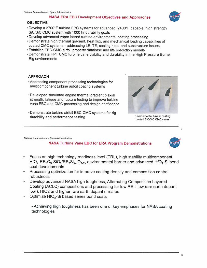
APPROACH
• Addressing component processing technologies for multicomponent turbine airfoil coating systems
• Developed simulated engine thermal gradient biaxial strength, fatigue and rupture testing to improve turbine vane EBC and CMC processing and design confidence
• Demonstrate turbine airfoil EBC-CMC systems for rig durability and performance testing Environmental barrier coating
coated SiC/SiC CMC vanes
7
National Aeronautics and Space Administration
• •
•
•
•
NASA Turbine Vane EBC for ERA Program Demonstrations
Focus on high technology readiness level (TRL), high stability multicomponent Hf02-RE20 3-Si02/RE2Si2_x0 7_2x environmental barrier and advanced Hf02-Si bond coat developments Processing optimization for improve coating density and composition control robustness Develop advanced NASA high toughness, Alternating Composition Layered Coating (ACLC) compositions and processing for low RE t' low rare earth dopant low k Hf02 and highe~ rare earth dopant silicates Optimize Hf02-Si based series bond coats
-Achieving high toughness has been one of key emphases for NASA coating technologies
8

National Aeronautics and Space Administration
Development and Processing of Directed Vapor Electron Beam -Physical Vapor Deposition (EB-PVD) •
- NASA programs in supporting processing developments and improvements with Directed Vapor Technologies International, Inc.
- Multicomponent thermal and environmental barrier coating vapor processing developments
- High toughness erosion resistant turbine coatings - Affordable manufacture of environmental barrier coatings
NAS~ond NASA Hybrid coat on SiC/SiC ESC on SiC/SiC Advanced multi-component and multilayer turbine ESC systems
Directed Vapor Processing Systems
9
National Aeronautics and Space Administration
•
';I(
s:£ ·c; .b en
-a ..... 0 f-
Thermal Gradient Tensile Creep Rupture Testing of Advanced Turbine Environmental Barrier Coating SiC/SiC CMCs
Advanced high stability turbine vane environmental barrier coatings demonstrated based turbine environmental barrier coatings being successfully tested for long-term creep rupture capability The new generation bond coat tested up to 2500F showed no major degradations The new CVI-MI with Hi-Nicalon TM Type S Type S fibers SiC/SiC CMCs also showed promise in creep resistance
1. 0 .---r---r---r--r---,--...,..-.,--.---r---r---r--r---,---r-r--1r--T-r--,---,
- - - -•-- -- CVI 10C3 80-P02-5 EBC ID 42 (3 .5.4), 10 ksi -- Prepreg MI1 849-02-001-2 EBC ID29 (3.5.3), 15 ksi
0.8 CVI-MI 12C-461-002 #5 APS Combustor EBC, 15ksi
0.6
0.4
0.2 ,.,
0.0 0
Tsurface = 2700F /.I Tinter face = 2500F / ' Tback = 2350F ,./ 15ksi //
i '
~_,Y • Tsurface = 2700F ./ Tsurface = 2700F Tinterface = 2350F
_,.... Tinterface = 2600F Tback = 2250F ~,,_,• Tback = 2550F 15ksi
200 400 600 800 1000 Time, hr Model ing is in progress
10

National Aeronautics and Space Administration
• NASA Turbine Environmental Barrier Coating Testing Developments
Advanced EBC top coats tested in coupons under laser heat flux cyclic rigs up 170ooc Coated subelements coating tested up 1500C under laser thermal gradient for 200 hr EBC systems show high stability in High Pressure Burner Rig Tests Thermal conductivity of 1.2 W/m-K met program goals
4.0 ~
~ 3.5
3.0
1600
&:. ·:; 1200 fti . ., 0
2.5
" ., § 0
2.0
~ 1.5
" 1.0 .<: 1-
High pressure burner rig , 16 atm, 31 hr u 0.5 al Ul
10 20 30 40 50 Time, hours
~ ~ 800 c.
400
E ~
11
National Aeronautics and Space Administration
• Advanced High Pressure Burner Rig Testing for Turbine Vanes
Scale I
Cooling air
12

National Aeronautics and Space Administration
Advanced High Pressure Burner Rig Testing for Turbine Vanes High Pressure Burner Rig test sections manufactured Nickel base superalloys and thermal barrier coatings used inner sections Total 6 SiC/SiC vanes coated 2 uncoated SiC/SiC turbine vanes tested at 2400F 2 coated SiC/SiC turbine vanes tested at 2500F 1 film-cooled vane under testing at 2600F
National Aeronautics and Space Administration
General Test Conditions
Fuel to air ratio F/A 0.045, mas air flow 1.5 lbm/s, pressure 1 0 atm, internal impingement or impingement + film cooling Inlet leading edge velocity 65 m/s, trailing edge 200+ m/s Cooling flow 0.05-01 lbm/s Pressure differential between "pressure" and "suction" side of the vanes are 7 to 1 0 psi symmet ry Plane
10.7 atm (142 psi)
150 •F, H=33.7 Btu/hr.ft2.•F
~ 10 atm (132 psi) \
2814 •F Gas Temp H=173 Btu/hr.ft2.•F
/ Heat Sink
Fixed in all direc
13
14

National Aeronautics and Space Administration
General Test Conditions- Continued
Fuel to air ratio F/A 0.045, mas air flow 1.5 lbm/s, pressure 10 atm (132psig), internal impingement or impingement+ film cooling at up to 10.7 atm (142 psig) Inlet leading edge velocity 65 m/s, trailing edge 200+ m/s Cooling flow 0.05-0.10 lbm/s Pressure differential between "pressure" and "suction"
Patran2010236-4·6o~atH2t · 29
FnngEI HeatTmnsfer. Stepl ,TotaiTme•l _1 Tempe~31\lo) {Nodal). Lif.oMorSectiOrt P.JI"tts. , At SECTION_POINT_I
Validated FEM modeling for temperature distributions
National Aeronautics and Space Administration
d• filV11J.Tl9<'
2430
2387
2343
2300
2257
2214
2171
2127
2084
2041
1998
1955
1911
1868
1825 1782
M-. 2 4 •I);:J ti'Nd 715 ;..-; t-1t1 1 78•00 ~N\J 1-4::'f>
High Pressure Burner Rig Testing for Validating EBC Coating and SiC/SiC Vane Components
Uncoated vanes tested 21 hours - Coated CVI and Prepreg Ml SiC/SiC vane successfully tested 31
and 21 hours respectively, at 2500 F+, reaching TRL of 5 - Turbine EBCs generally intact (some minor partial coating top coat
spalling for the Prepreg Ml SiC/SiC vane) - Minor CMC vane degradations after the testing
Coated CVI vane after 31 hour testing at 2500°F+ coating temperature
Coated Prepreg vane after 21 hour testing at 2500°F+ coating temperature
•
15
•
16
National Aeronautics and Space Administration
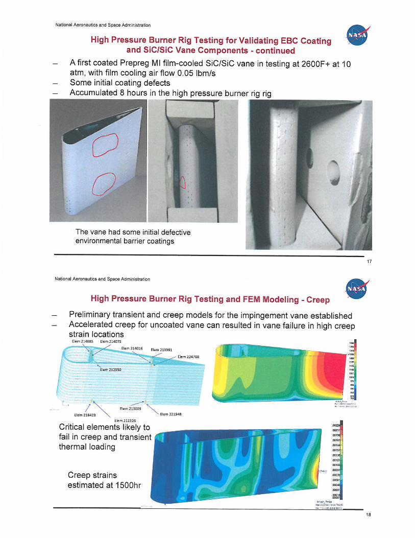
High Pressure Burner Rig Testing for Validating EBC Coating and SiC/SiC Vane Components - continued
A first coated Prepreg Ml film-cooled SiC/SiC vane in testing at 2600F+ at 10 atm, with film cooling air flow 0.05 lbm/s Some initial coating defects Accumulated 8 hours in the high pressure burner rig rig
0 The vane had some initial defective environmental barrier coatings
National Aeronautics and Space Administration
,
High Pressure Burner Rig Testing and FEM Modeling - Creep
Preliminary transient and creep models for the impingement vane established Accelerated creep for uncoated vane can resulted in vane failure in high creep strain locations
' Elem 212550
Elem 213961
~Eiem22476B ,...
--Eiem 213009 """-"'-. Elem 221548
Elem 212326
Critical elements likely to fail in creep and transient thermal loading
Creep strains estimated at 1500hr
.00031
·'"'" .ooan $ .. UU'mqt M.t;.t:!~7« ~OliMO 1-lr~lf J(lti.J.Hclti\lit
17
18

National Aeronautics and Space Administration
High Pressure Burner Rig Testing and FEM Modeling- Thermal Transients •
Transient stress modeling for 0 degree plies
Maximum Tensile Stresses
in 0 Degree layer5o..,.1~$ i~o~mtt*>PS .,..------ ------- ~~-V,M l~lJ~fC I
,_ _ :-::;
" ~150 ~:~~~==~~~;;;;;;;;;;;;;;;-----~ """"""213961
i --2 14016
i 100 ~214685 u - 214705 ~ ~ so ~f-------------------
20 40 60 80 100 120
·SO .L....--------.;;n"'m""•. -:-::,.c:-, --------
Tr~lll>tf't lell'l9t•ahur Prolilt @)A.USS-:.
~-------~-~·-·----------,
Maximum Shear Stress in 0 Degree layers
(1-~u':'0 I:II~ Z:~UctooUU4 \------------'"""= ""'UM"----- -+-212326
- .u3009
+----- - ----- - ------ - 21&423 1 221548
0 ·--~--~--~---~--~-~ 0 20 40 80 100 120
19
National Aeronautics and Space Administration
High Pressure Burner Rig Testing and FEM Modeling- Thermal Transients - continued •
Transient stress modeling for 90 degree plies Tr-.tfltlt ""f'ttatul'e PIOMit I' A ,HS5 ~eoc.
Maximum Tensile Stress in 90 Degree Layers
350 .AEii- 110549 .
300
250
.......... ..__ 200 Ell:mll2C32 EIAm l002!13
150
so
20 40 60 80 100
·SO Time, sec
200
180
160
140
~110175 11 120
...-110549 1 100
~mo37 1
60
40
120 20
•c ~
MuimumShear Stresses in 90 Degree layers
Elei 110549 ;.: ~10175
. . ....... t/1--\--1,.-------_E~~.:.~~~_? ___ E.I~~~7-03 ___ -+-109703
-+110175
+t---++---------------- -.lr 110549
- 112037
40 100 120
I
20

National Aeronautics and Space Administration
Summary • • Vapor deposition turbine EBCs developed with some confidence for
complex large vane components • An ERA turbine coating downselected and showed high stability and
long-term durability on state of the art SiC/SiC CMCs • The vapor based EBC processing approaches demonstrated vane
EBC composition realization, acceptable coating surface roughness and thickness controls
• Multiple advanced turbine environmental barrier coating coated SiC/SiC CMC vanes tested in engine relevant rig combustion environments, showing component viability and initial durability, demonstrating TRL of 5 under the NASA ERA program
21
National Aeronautics and Space Administration
• Conclusions • The EBC developments have major advances for turbine airfoil
applications in composition and processing with durability and performance
• Realistic impingement and film cooled vane component testing can be achieved in the High Pressure Burner Rig environments
• Turbine EBCs can help improve the turbine durability in the harsh engine environments, addressing key HPT turbine airfoil development issues, in particular, thermal stress resistance and environment related degradations in complex transient cyclic loading, creep and harsh combustion environments
• Coating process control for large airfoil components still need improvements
22

National Aeronautics and Space Administration
Future Plans • Film-cooled vane(s) continued to be tested • Next generation environmental barrier coating systems also being
incorporated • CFD models for full 30 vane high pressure burner rig testing in
progress • Continued vane subelement testing for EBC-CMC cyclic durability
improvements and model developments
23