complex-1 operation manual · complex-1 modular synthesizer 7 playing and using complex-1 loading...
TRANSCRIPT

COMPLEX-1 MODULAR SYNTHESIZEROPERATION MANUAL

The information in this document is subject to change without notice and does not represent a commitment on the part of Propellerhead Software AB. The software described herein is subject to a License Agreement and may not be copied to any other media except as specifically allowed in the License Agreement. No part of this publication may be copied, reproduced or otherwise transmitted or recorded, for any purpose, without prior written permission by Propellerhead Software AB.
©2018 Propellerhead Software and its licensors. All specifications subject to change without notice. Reason, Reason Intro, Reason Lite and Rack Extension are trademarks of Propellerhead Software. All other commercial symbols are protected trademarks and trade names of their respective holders. All rights reserved.

Complex-1 Modular Synthesizer

COMPLEX-1 MODULAR SYNTHESIZER4
Introduction
Complex-1 is a monophonic/duophonic (paraphonic) modular synthesizer from Propellerhead Software, bringing the quirks, freedom and sonic depth of modular synthesis to your Reason rack. Boasting a 4x oversampled synthesis engine, a freely routable signal and modulation path and a sound like nothing else, Complex-1 is a synth lover's dream machine.
The modules in Complex-1 bring a mix of modular synth ideologies to the Reason rack. The Complex Oscillator, Low Pass Gates and Shaper modules, build on the works on Don Buchla (or West Coast style) and the regular Oscillator and ladder design Filter module derive more from the Bob Moog school of synth design. Combine them anyway you like and craft your very own unique synth sounds. Almost any parameter can be modulated - also at audio rate.
If you're a seasoned modular synth enthusiast, you can dive right in. If this kind synth is new to you, it can look a bit daunting, but it's actually surprisingly easy to get going. Load up any of the included patches to get you going, and start your sonic exploration there. Nothing can break, and if things go weird (like, in a bad way), there's the Undo function to your rescue.
Most people associate modular synths with lab coats and glitchy noise soundscapes, but if all you want is a beefy bass - let Complex-1 surprise you. Its modular madness aside, it's also a really awesome-sounding synthesizer, capable of perfectly playable instrument sounds and yes, beefy basses too.
COMPLEX-1 MODULAR SYNTHESIZER 5
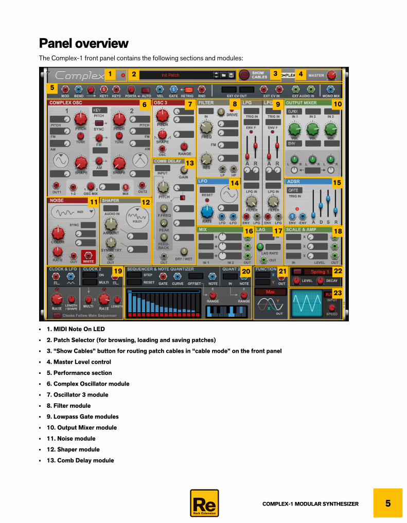
Panel overviewThe Complex-1 front panel contains the following sections and modules:
• 1. MIDI Note On LED
• 2. Patch Selector (for browsing, loading and saving patches)
• 3. “Show Cables” button for routing patch cables in “cable mode” on the front panel
• 4. Master Level control
• 5. Performance section
• 6. Complex Oscillator module
• 7. Oscillator 3 module
• 8. Filter module
• 9. Lowpass Gate modules
• 10. Output Mixer module
• 11. Noise module
• 12. Shaper module
• 13. Comb Delay module
1
6 7
2 3
5
4
8 9 10
13
14 15
16 17 18
11 12
19 20 21 22
23

COMPLEX-1 MODULAR SYNTHESIZER6
• 14. LFO module
• 15. ADSR Envelope module
• 16. Signal Mixer module
• 17. Control signal Lag module
• 18. Scale & Amp module
• 19. Clock & LFO modules
• 20. Sequencer & Note Quantizer modules
• 21. Function module
• 22. Reverb module
• 23. Oscilloscope
About the signal flowSince Complex-1 is a modular synthesizer you can freely connect sections and modules together, to create your own unique signal flows. The only (hidden) pre-configured routings are these:
Complex-1 pre-configured audio signal flow.
• The mixed and panned signals from the Output Mixer module are routed in stereo, via the Reverb module (if active), to the Master Level control and then output on the L & R Main Outs on the Complex-1 rear panel.
: audio signal
OUTPUT MIXER
REVERB
MASTERVOLUME
OUT LOUT R
L
R

COMPLEX-1 MODULAR SYNTHESIZER 7
Playing and using Complex-1
Loading and saving patches
Loading and saving patches is done in the same way as with any other internal Reason device. See the “Sounds and Patches” chapter in the Reason/Reason Intro/Reason Lite Operation Manual pdf for details. As with all Rack Extensions, you can find the included patches by clicking "Rack Extensions" in the Reason browser, navigating to the Complex-1 Modular Synthesizer folder and opening it. Don't miss the Templates and Examples subfolder, which contains many useful routings and tricks!
Global output controls
Master LevelThis is the main stereo output volume control.
Connecting modulesGenerally, to get a sound out of a modular synthesizer you would have to connect the different modules using patch cables. The same thing goes for the Complex-1 synthesizer. By connecting the modules you can create your own custom “signal flow” and modulation assignments. This opens up enormous possibilities of creating complex signals flows and modulations.
In the default “normal” mode there are no visible cables on the Complex-1 panel. However, as soon as you click and hold on an output jack on the front panel the panel temporarily switches to “cable mode”, where all cables are shown:
Now, you could drag the mouse pointer to an input jack, to connect the signal source to the destination. This is described in detail in “Connecting modules in “cable mode””.

COMPLEX-1 MODULAR SYNTHESIZER8
Connecting modules using the display pop-up menusIf you like you could also connect (or reroute or disconnect) modules using the pop-up displays on the front panel:
1. Select a signal source by clicking in the desired destination display and selecting a source from the pop-up menu that appears:

COMPLEX-1 MODULAR SYNTHESIZER 9
2. Once you have selected the signal source and released the mouse button the signal source name is shown in plain text in the display:
• Some modulation inputs also have an accompanying attenuation knob, which you can use to control the modulation amount:
• Instead of routing signals by clicking on displays, you can connect virtual cables between source and destinations - in “cable mode”, see “Connecting modules in “cable mode”” below.The two types of signal routing methods have the exact same effect: if you route a signal via a display, a cable is automatically connected in “cable mode” in the background - and vice versa.
Disconnecting and rerouting modules using the display pop-up menusD To disconnect or reroute signals, click the desired destination display and select “Off” to disconnect - or another sig-
nal source to reroute - from the pop-up menu.
Connecting modules in “cable mode”If you want to remain in “cable mode” to continue to connect/disconnect/reroute modules you can do this.
Entering “cable mode”D Click the Show Cables button to toggle between “normal” and “cable mode”:
The front panel in “cable mode”.

COMPLEX-1 MODULAR SYNTHESIZER10
• Output jacks on the front panel are colored either in red, blue, grey or green.When connected, the cables get the same color as the output jack they originate from.
• Input jacks are grey on a dark grey rectangular background.
• Cables can be patched from one output jack to several input jacks (in parallel).Several output jacks cannot be connected to a single input jack, though.
! Note that you cannot patch from an input to another input or from an output to another output.
Connecting cables1. Click and hold on a (colored) output jack, then drag the mouse pointer to the desired (grey) input jack and release
the mouse button.You could patch in the other direction as well, from an input jack to an output jack.
The Key output is now connected to the Complex Oscillator Pitch modulation input.
When you exit “cable mode” the display shows the signal source in text. The output jack also shows a figure, which indicates how many destinations it is currently connected to:
The signal source assignment in “normal” mode (i.e. when you have exited “cable mode”).
2. Repeat the procedure to connect other output and input jacks.
! Note that you could connect the same output jack to several other input jacks.
Highlighting cablesD Click and hold on a connected input or output jack to highlight the cable(s) and see where they are connected.
This is especially useful if the panel has a lot of cables, so you can see more clearly what’s connected to what.
Disconnecting cablesD Click and hold on a connected input jack, then drag the mouse pointer away from the input jack and release the
mouse button.Alternatively, hold down [Cmd](Mac) or [Ctrl](Win) and click on the input jack.
D To disconnect ALL cables from an output jack, hold down [Cmd](Mac) or [Ctrl](Win) and click on the output jack.
! Note that you cannot disconnect individual cables at an output jack - you always have to do that at the input jack.
Rerouting cablesD Click and hold on a connected input jack, then drag the mouse pointer to another unused input jack and release the
mouse button.
D To disconnect ALL cables from an output and then connect the output to a new input jack, hold down [Cmd](Mac) or [Ctrl](Win) and then click and hold on the output jack and drag to the desired input jack, and release the mouse button.
! Note that you cannot reroute individual cables at an output jack - you always have to do that at the input jack.
COMPLEX-1 MODULAR SYNTHESIZER 11
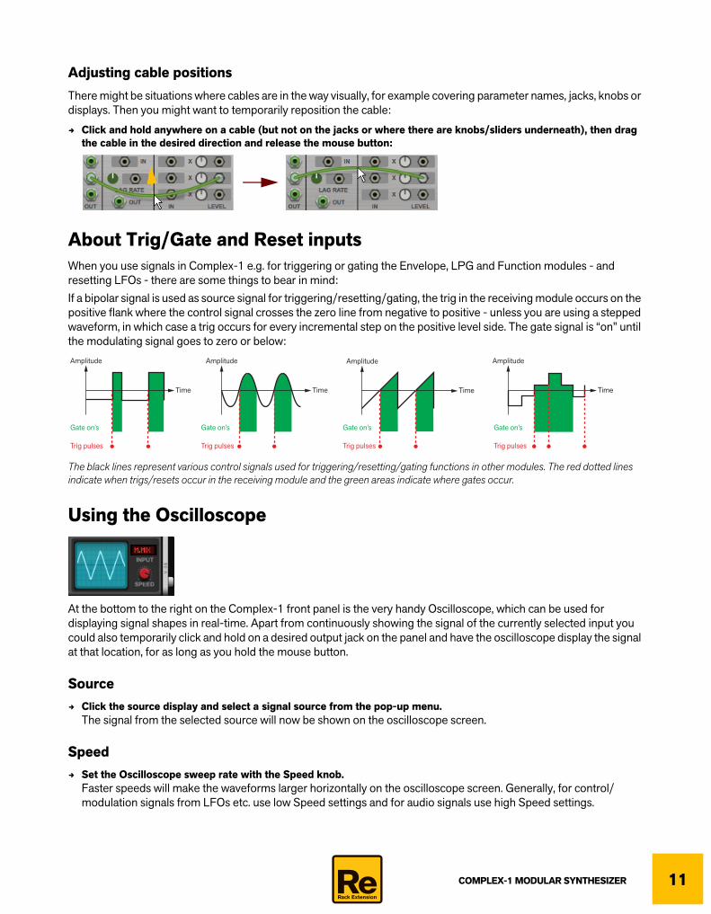
Adjusting cable positionsThere might be situations where cables are in the way visually, for example covering parameter names, jacks, knobs or displays. Then you might want to temporarily reposition the cable:
D Click and hold anywhere on a cable (but not on the jacks or where there are knobs/sliders underneath), then drag the cable in the desired direction and release the mouse button:
About Trig/Gate and Reset inputsWhen you use signals in Complex-1 e.g. for triggering or gating the Envelope, LPG and Function modules - and resetting LFOs - there are some things to bear in mind:If a bipolar signal is used as source signal for triggering/resetting/gating, the trig in the receiving module occurs on the positive flank where the control signal crosses the zero line from negative to positive - unless you are using a stepped waveform, in which case a trig occurs for every incremental step on the positive level side. The gate signal is “on” until the modulating signal goes to zero or below:
The black lines represent various control signals used for triggering/resetting/gating functions in other modules. The red dotted lines indicate when trigs/resets occur in the receiving module and the green areas indicate where gates occur.
Using the Oscilloscope
At the bottom to the right on the Complex-1 front panel is the very handy Oscilloscope, which can be used for displaying signal shapes in real-time. Apart from continuously showing the signal of the currently selected input you could also temporarily click and hold on a desired output jack on the panel and have the oscilloscope display the signal at that location, for as long as you hold the mouse button.
SourceD Click the source display and select a signal source from the pop-up menu.
The signal from the selected source will now be shown on the oscilloscope screen.
SpeedD Set the Oscilloscope sweep rate with the Speed knob.
Faster speeds will make the waveforms larger horizontally on the oscilloscope screen. Generally, for control/modulation signals from LFOs etc. use low Speed settings and for audio signals use high Speed settings.
Amplitude
Time
Amplitude
Trig pulses
Gate on’s Gate on’s Gate on’s Gate on’s
Time
Amplitude
Time
Amplitude
Time
Trig pulses Trig pulses Trig pulses

COMPLEX-1 MODULAR SYNTHESIZER12
Panel reference
The Performance section
The Performance section at the top is where you can route various control signals from your MIDI keyboard to the desired modules in Complex-1. Here you can also route external audio and CV signals to destinations in Complex-1 - and also route signals from Complex-1 to other devices in the Reason rack.Since you cannot connect cables straight from the front panel of Complex-1 to jacks on the rear panels of devices in the Reason rack, there is a set of jacks on the rear panel of Complex-1 for this purpose (see “Rear panel connections”).
q Note that you can connect the outputs described below to multiple destinations, if you want to control several destinations simultaneously.
Mod outputThis output sends out a positive unipolar CV signal based on the current value of the Mod Wheel on your MIDI keyboard. You could, for example, connect the Mod output to a frequency modulation input e.g. on a Filter module or similar.
Bend outputThis output sends out a bipolar CV signal based on the current value of the Pitch Bend control on your MIDI keyboard. Since Pitch Bend is also sent out on the Key 1 and Key 2 outputs (see below) you don’t have to connect this if you only want to control regular pitch bend. However, if you want to control other parameters like Filter Freq or similar separately from the Pitch Bend control this could be very useful.
Bend to Key rangeThe Key 1 and Key 2 outputs described below can also send out pitch bend control signals if desired.
D Set the desired Bend range for the Key 1 and Key 2 outputs with the Bend to Key knob.The set bend range will now be available on the Key 1 and Key 2 outputs - including the actual note values.
Range: +/- 24 semitones.
Key 1 outputThe Key 1 output sends out a pitch signal which corresponds to the last played note on your MIDI keyboard/On-screen Piano Keys. For example, connecting the Key 1 output to the pitch input on an oscillator module makes it possible to control the oscillator pitch from a MIDI keyboard. Besides the note/pitch information the output can also send Pitch Bend information from your MIDI keyboard, according to the range you have defined with the Bend to Key knob, see “Bend to Key range”. ! Note that it’s only the note/pitch and pitch bend information that is sent on this output. Gate and Velocity signals
have their own separate outputs (see below).

COMPLEX-1 MODULAR SYNTHESIZER 13
Key 2 outputIf connected, the Key 2 output sends out a second pitch signal allowing you to play duophonic/paraphonic on your MIDI keyboard/On-screen Piano Keys - if you connect the Key 2 output to a second oscillator or similar. Besides the note/pitch information the output also sends any Pitch Bend information from your MIDI keyboard, according to the range you have defined with the Bend to Key knob, see “Bend to Key range”. The Pitch Bend signal is the same as for the Key 1 output.! If no keys are held the first note you play will always send note/pitch information on both the Key 1 and Key 2 out-
puts. If you hold the key and then press another key this will send note/pitch information on the Key 2 output.
! Note that it’s only the note/pitch information that is sent on this output. Gate and Velocity signals have their own separate outputs (see below).
! Note that as soon as the Key 2 output is connected to a destination (even if the connection doesn’t do anything), the Key 2 function will be active.
PortaPortamento makes note pitches glide from the previous note to the new one.
D Set the time it should take to glide between notes with the Porta knob. The portamento information is sent together with the note/pitch signal on the Key 1 and Key 2 outputs described above.
Auto (portamento)D Click the Auto button to introduce Portamento only when you play in a legato fashion, i.e. when you play a new note
without having released the previous note first.Set the portamento time with the Porta knob described above.
Vel outputThis output sends out a control signal based on the last Keyboard Velocity value sent from your MIDI keyboard/On-screen Piano Keys. A typical example would be to connect the Vel output to a Frequency modulation input on a Filter module or similar. See “Making the LPG module velocity sensitive” for another example.
Gate outputThis output sends out a gate signal each time you hold a note on your MIDI keyboard/On-screen Piano Keys. Typically, you would connect the Gate output to a gate/trig input e.g. on an Envelope module or similar.
RetrigD Click the Retrig button if you want a new trig signal to be output also when you play in a legato fashion, i.e. when
you play a new note without having released the previous note first.If not active, new trig signals will only be sent when you play a new note after having released any previous notes.
Rnd outputThis output sends out a random bipolar CV value each time each time a MIDI note is received.
Ext CV Out 1&2Here you can route two separate modulation signals from Complex-1 to the CV Out 1 and CV Out 2 output jacks on the rear panel. The CV Out jacks can then be connected to the desired modulation destinations on other devices in the Reason rack.
COMPLEX-1 MODULAR SYNTHESIZER14
Ext CV In 1&2Here you can route the two separate CV modulation input signals from the CV In 1 and CV In 2 inputs on the rear panel to the desired destinations in Complex-1.
Ext Audio In 1&2Here you can route the two separate audio signals from the Audio In 1 and Audio In 2 inputs on the rear panel to the desired destinations in Complex-1.
Mono MixHere you can route the mono output signal mix from Complex-1 back into the signal chain again, for interesting feedback applications.! Beware of any feedback loops that might cause loud volumes!
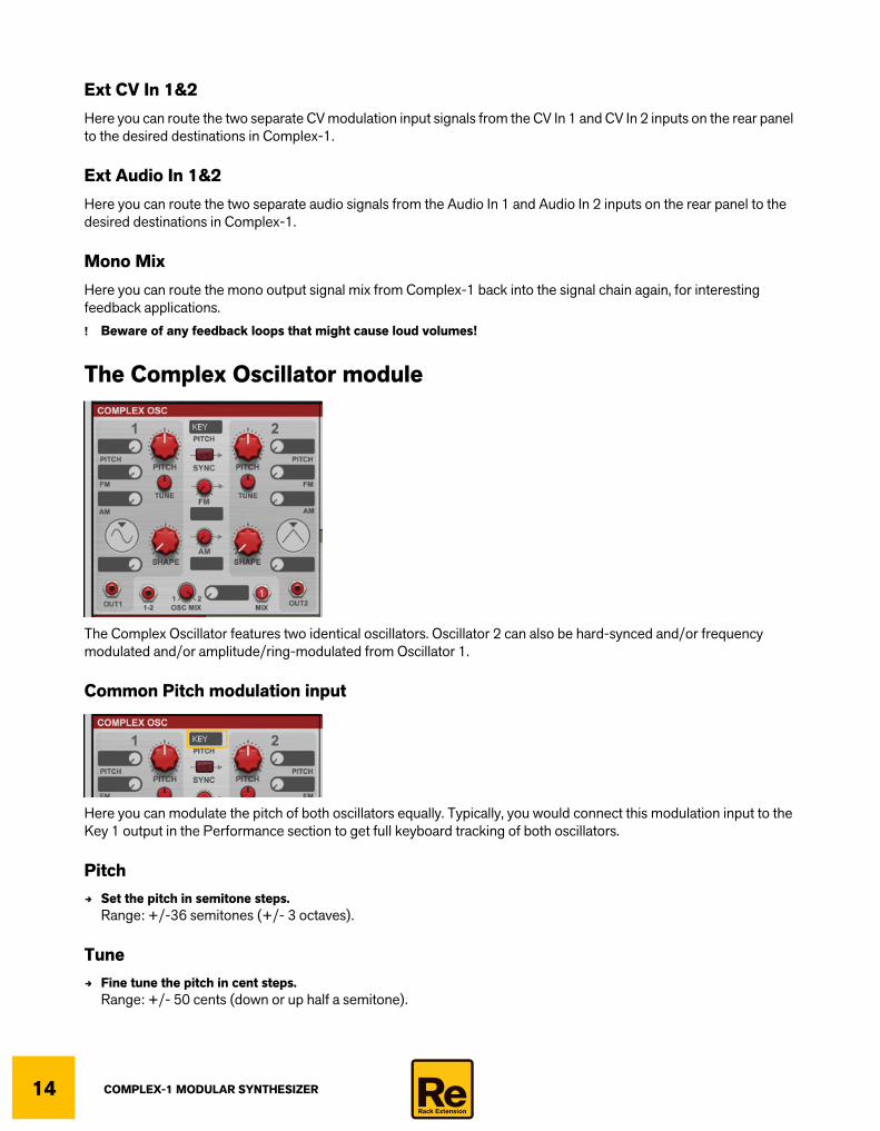
The Complex Oscillator module
The Complex Oscillator features two identical oscillators. Oscillator 2 can also be hard-synced and/or frequency modulated and/or amplitude/ring-modulated from Oscillator 1.
Common Pitch modulation input
Here you can modulate the pitch of both oscillators equally. Typically, you would connect this modulation input to the Key 1 output in the Performance section to get full keyboard tracking of both oscillators.
PitchD Set the pitch in semitone steps.
Range: +/-36 semitones (+/- 3 octaves).
TuneD Fine tune the pitch in cent steps.
Range: +/- 50 cents (down or up half a semitone).
COMPLEX-1 MODULAR SYNTHESIZER 15
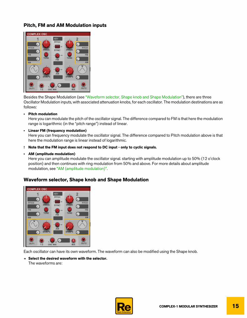
Pitch, FM and AM Modulation inputs
Besides the Shape Modulation (see “Waveform selector, Shape knob and Shape Modulation”), there are three Oscillator Modulation inputs, with associated attenuation knobs, for each oscillator. The modulation destinations are as follows:
• Pitch modulationHere you can modulate the pitch of the oscillator signal. The difference compared to FM is that here the modulation range is logarithmic (in the “pitch range”) instead of linear.
• Linear FM (frequency modulation)Here you can frequency modulate the oscillator signal. The difference compared to Pitch modulation above is that here the modulation range is linear instead of logarithmic.
! Note that the FM input does not respond to DC input - only to cyclic signals.
• AM (amplitude modulation)Here you can amplitude modulate the oscillator signal. starting with amplitude modulation up to 50% (12 o’clock position) and then continues with ring modulation from 50% and above. For more details about amplitude modulation, see “AM (amplitude modulation)”.
Waveform selector, Shape knob and Shape Modulation
Each oscillator can have its own waveform. The waveform can also be modified using the Shape knob.
D Select the desired waveform with the selector.The waveforms are:

COMPLEX-1 MODULAR SYNTHESIZER16
• PulsewidthThe pulsewidth can be continuously modified from 50% to 1% duty cycle with the Shape knob:
• Sine-PulseThe wave shape can be continuously modified with the Shape knob:
• Tri-RampThe wave shape can be continuously modified from triangle to ramp (sawtooth) with the Shape knob:
• Shape modulationHere you can modulate the Shape control for the currently selected waveform (see “Waveform selector, Shape knob and Shape Modulation” for more details about the waveforms).
SHAPE
SHAPE
SHAPE
Amplitude
Time
Amplitude
Time
Amplitude
Time
SHAPE
SHAPE
SHAPE
Amplitude
Time
Amplitude
Time
Amplitude
Time
SHAPE
SHAPE
SHAPE
Amplitude
Time
Amplitude
Time
Amplitude
Time

COMPLEX-1 MODULAR SYNTHESIZER 17
Oscillator 1 > 2 modulation
Besides the individual oscillator modulation possibilities (see “Pitch, FM and AM Modulation inputs”), you can also modulate Oscillator 2 from Oscillator 1 in a number of different ways:
• SyncHard sync is when one oscillator restarts the period of another oscillator, so that they will have the same base frequency. If you change or modulate the pitch/frequency of the synced oscillator you will get the characteristic sound associated with oscillator sync. In Complex-1 you can hard sync Oscillator 2 from Oscillator 1. In Complex-1 the characteristic “sync sound” is produced when Oscillator 2’s Pitch parameter is modulated.
This is the principle for oscillator hard sync:
Oscillator 2 hard synced from Oscillator 1.
Time
Level
Time
Level
Oscillator 2
Time
Level
Oscillator 2 at slightlyhigher frequency(synced by Oscillator 1)
Time
Level
Oscillator 2(synced by Oscillator 1)
Oscillator 1
COMPLEX-1 MODULAR SYNTHESIZER18
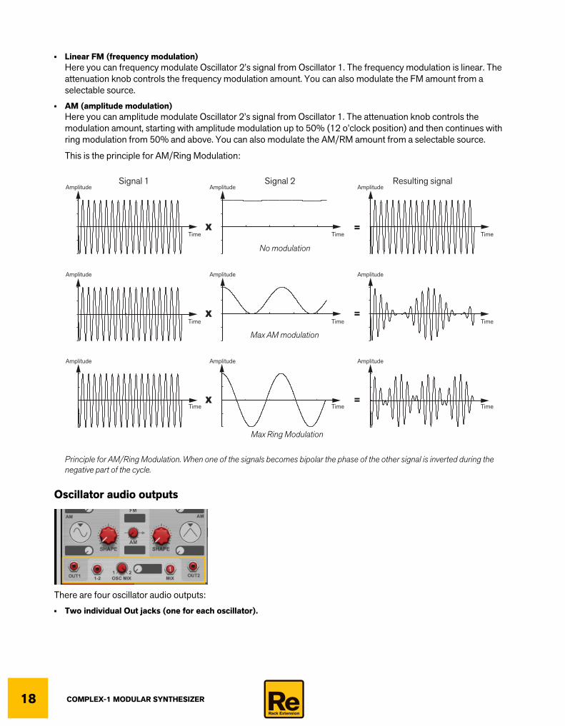
• Linear FM (frequency modulation)Here you can frequency modulate Oscillator 2’s signal from Oscillator 1. The frequency modulation is linear. The attenuation knob controls the frequency modulation amount. You can also modulate the FM amount from a selectable source.
• AM (amplitude modulation)Here you can amplitude modulate Oscillator 2’s signal from Oscillator 1. The attenuation knob controls the modulation amount, starting with amplitude modulation up to 50% (12 o’clock position) and then continues with ring modulation from 50% and above. You can also modulate the AM/RM amount from a selectable source.
This is the principle for AM/Ring Modulation:
Principle for AM/Ring Modulation. When one of the signals becomes bipolar the phase of the other signal is inverted during the negative part of the cycle.
Oscillator audio outputs
There are four oscillator audio outputs:
• Two individual Out jacks (one for each oscillator).
TimeTimeX =
=
=
X
X
Amplitude
Time
Amplitude
Time
Amplitude
Time
Amplitude
Time
Amplitude
Time
Amplitude
AmplitudeSignal 1 Signal 2 Resulting signal
Time
Amplitude
Time
Amplitude
No modulation
Max AM modulation
Max Ring Modulation

COMPLEX-1 MODULAR SYNTHESIZER 19
• The 1-2 jack outputs the “Oscillator 1 minus Oscillator 2” signal.This is very useful for special sounds and effects. For example, if you subtract a square wave from a triangle wave of the same pitch you would get a signal that could look as follows:
• A Mix jack which outputs both oscillator signals at the currently set Osc Mix level (see below).
D Set the output signal mix between Oscillator 1 and 2 with the Osc Mix knob.The mixed signal is output on the Mix output jack (see above).
The Oscillator 3 module
The Oscillator 3 can be used as a traditional oscillator or as an LFO.
PitchD Set the pitch in semitone steps with the Pitch knob.
Range: +/-36 semitones (+/- 3 octaves).
ShapeD Modify the wave shape continuously from inverted ramp, via triangle, to ramp:
RangeD Change oscillator/LFO Pitch range in a linear fashion.
Range: ~0.01 Hz to 2x the Pitch setting (see “Pitch” above).
! Note that the Range parameter is more precise around the center position, for better detuning precision.
AmplitudeOSC1 OSC1-OSC2OSC2
Time
Amplitude
Time
Amplitude
Time
SHAPE
SHAPE
SHAPE
Amplitude
Time
Amplitude
Time
Amplitude
Time
COMPLEX-1 MODULAR SYNTHESIZER20
Modulation inputsThere are three Oscillator Modulation inputs, with associated attenuation knobs. The modulation destinations are as follows:
• 2 x Pitch modulationHere you can modulate the pitch of the oscillator signal from two separate modulation sources. The modulation is logarithmic.
• Wave shape modulationHere you can modulate the Modifier control for the waveform (see “Shape”).
Oscillator 3 audio outputThis is the audio signal output of Oscillator 3.
The Noise module
This versatile module can be used for generating everything from various “standard” noise types to a wide variety of “pitched” noises. The Noise module also features a Sync modulation input, which makes it possible to generate formant type of sounds when reset (synced) from an oscillator signal.
TypeD Select the desired noise type by clicking the selector and choosing from the pop-up menu.
The noise types are:
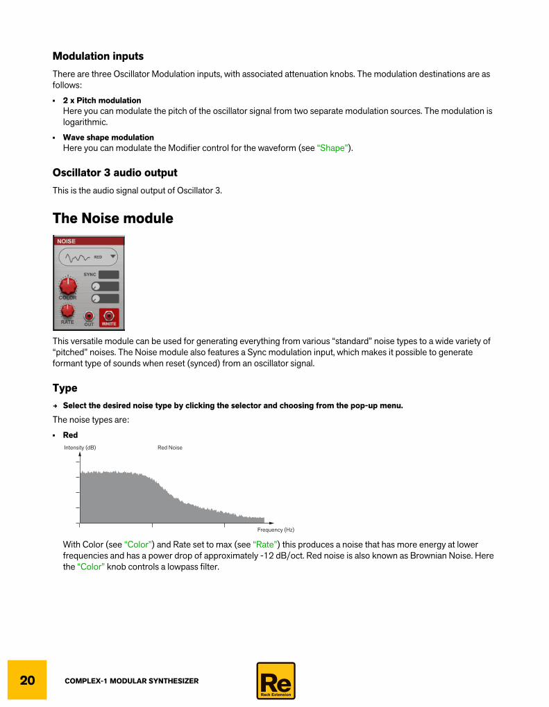
• Red
With Color (see “Color”) and Rate set to max (see “Rate”) this produces a noise that has more energy at lower frequencies and has a power drop of approximately -12 dB/oct. Red noise is also known as Brownian Noise. Here the “Color” knob controls a lowpass filter.
Intensity (dB) Red Noise
Frequency (Hz)
COMPLEX-1 MODULAR SYNTHESIZER 21
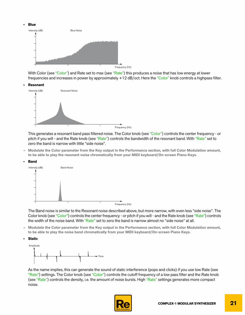
• Blue
With Color (see “Color”) and Rate set to max (see “Rate”) this produces a noise that has low energy at lower frequencies and increases in power by approximately +12 dB/oct. Here the “Color” knob controls a highpass filter.
• Resonant
This generates a resonant band pass filtered noise. The Color knob (see “Color”) controls the center frequency - or pitch if you will - and the Rate knob (see “Rate”) controls the bandwidth of the resonant band. With “Rate” set to zero the band is narrow with little “side noise”.
q Modulate the Color parameter from the Key output in the Performance section, with full Color Modulation amount, to be able to play the resonant noise chromatically from your MIDI keyboard/On-screen Piano Keys.
• Band
The Band noise is similar to the Resonant noise described above, but more narrow, with even less “side noise”. The Color knob (see “Color”) controls the center frequency - or pitch if you will - and the Rate knob (see “Rate”) controls the width of the noise band. With “Rate” set to zero the band is narrow almost no “side noise” at all.
q Modulate the Color parameter from the Key output in the Performance section, with full Color Modulation amount, to be able to play the noise band chromatically from your MIDI keyboard/On-screen Piano Keys.
• Static
As the name implies, this can generate the sound of static interference (pops and clicks) if you use low Rate (see “Rate”) settings. The Color knob (see “Color”) controls the cutoff frequency of a low pass filter and the Rate knob (see “Rate”) controls the density, i.e. the amount of noise bursts. High “Rate” settings generates more compact noise.
Intensity (dB) Blue Noise
Frequency (Hz)
Intensity (dB) Resonant Noise
Frequency (Hz)
Intensity (dB) Band Noise
Frequency (Hz)
Amplitude
Time

COMPLEX-1 MODULAR SYNTHESIZER22
• Binary This generates random series of 1 and 0 - in practice a type of raw aliasing square/pulse wave. The Color knob (see “Color”) controls the pitch - and the Rate knob (see “Rate”) controls the density of the on/off bursts. With “Rate” set to zero the pitch is steady.
q Modulate the Color parameter from the Key output in the Performance section, with full Color Modulation amount, to be able to play the binary noise chromatically from your MIDI keyboard/On-screen Piano Keys.
• Buffer
This algorithm produces a range of noises, from tonal up to almost white noise, by individually amplitude modulating each sample in a randomly generated wave table with noise. At low Rate settings (see “Rate”) there is no modulation, which results in a cleaner “steady” tone. At higher Rate settings, more noise modulation is introduced, which results in a more “noisy” signal. The Color knob (see “Color”) controls the pitch.
q Modulate the Color parameter from the Key output in the Performance section, with full Color Modulation amount, to be able to play the noise chromatically from your MIDI keyboard/On-screen Piano Keys.
ColorD Change the frequency content or pitch in the noise with the Color knob.
The parameter has different character depending on the selected noise Type. For more details, see “Type” above.
• The Color parameter can also be modulated from a desired modulation source (to the right of the Color knob).
RateD Change the output rate/density/character of the noise with the Rate knob.
The parameter produces different character depending on the selected noise Type. For more details, see “Type” above.
• The Rate parameter can also be modulated from a desired modulation source (below the Color modulation).
Time
Amplitude
= sample
Time
Amplitude
= sample
= random noise modulation
Time
Amplitude
= sample
= random noise modulation

COMPLEX-1 MODULAR SYNTHESIZER 23
SyncD Select a modulation source to sync/restart the noise generation.
In the “digital world” it’s possible to generate harmonic signals by restarting - or syncing - noise. This can be done since the exact same series of noise samples can be restarted over and over again - and this is a prerequisite to be able to generate harmonic signals. In the analog world this wouldn’t be possible, since noise is completely random by nature.
When the noise is synced from an oscillator - or other bipolar signal source - the noise restarts every time the syncing oscillator signal begins a positive “flank” (the red lines in the picture below). When the syncing oscillator’s signal level is static or declining, random noise is output instead. This means that the audible effect will very much depend on the shape of the syncing oscillator’s signal. For example, a sawtooth ramp signal will play back the synced noise almost to 100% (Example 1 in the picture below), whereas a square wave signal will play back almost 100% random noise (since the positive flank is very short). Depending on selected noise Type, Color and Rate settings you will also get different sonic results.
The picture below shows two examples of syncing noise from an oscillator signal at audio rate. The noise signal is colored in a gradient to make it easier to see the part of the noise that is restarted and repeated. The red parts of the syncing oscillator’s signals indicate where in the cycle the noise is restarted and repeated. The grey line in the example to the bottom right indicates where there is random noise in the cycle.
Noise restarted (synced) on the Sync input from a ramp oscillator signal and a sinewave signal respectively.
The output signal in the example above has the base frequency of the resetting/syncing oscillator and the harmonic content of the repeated series of noise samples.
Time
Level
Time
Level
Noise signal
Example 1: noise synced by a ramp signal: Example 2: noise synced by a sinewave signal:
Time
Level
Output signal(synced by Oscillator)
Oscillator signal onthe Sync input Time
Level
Time
Level
Time
Level
COMPLEX-1 MODULAR SYNTHESIZER24
Outputs• The Out jack outputs the processed noise, as defined with the parameters in the Noise module.
• The White jack always outputs a steady white noise, regardless of the parameter settings in the Noise module.
White noise outputs all frequencies in the spectrum at equal intensity.
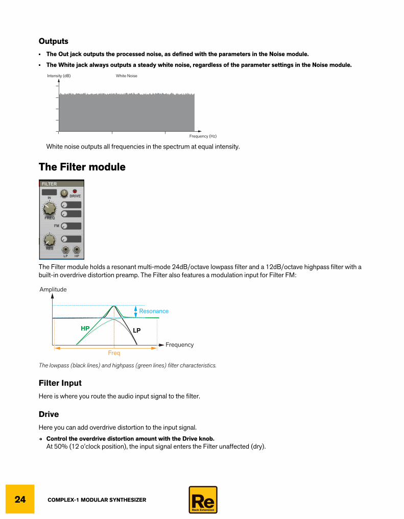
The Filter module
The Filter module holds a resonant multi-mode 24dB/octave lowpass filter and a 12dB/octave highpass filter with a built-in overdrive distortion preamp. The Filter also features a modulation input for Filter FM:
The lowpass (black lines) and highpass (green lines) filter characteristics.
Filter Input
Here is where you route the audio input signal to the filter.
Drive
Here you can add overdrive distortion to the input signal.
D Control the overdrive distortion amount with the Drive knob.At 50% (12 o’clock position), the input signal enters the Filter unaffected (dry).
Intensity (dB) White Noise
Frequency (Hz)
Frequency
Amplitude
Resonance
Freq
LPHP

COMPLEX-1 MODULAR SYNTHESIZER 25
Freq
D Set the cutoff frequency with the Freq knob.Range: 16.4 Hz to 16.74 kHz.
• The cutoff frequency can also be modulated from desired modulation sources (to the right of the Freq knob).
q Note that there are two separate Freq modulation inputs, which makes it possible to modulate the cutoff frequency from two separate sources.
Res
D Set the resonance amount.At maximum amount the filter will self-resonate.
• The resonance can also be modulated from a desired modulation source (to the right of the Res knob).
FM
The FM modulation input allows for linear frequency modulation of the cutoff frequency.
q Modulate the cutoff frequency from an oscillator signal to generate the classic “Filter FM sound”.
LP and HP Outputs• The LP jack outputs the lowpass filtered signal.
• The HP jack outputs the highpass filtered signal.
q Note that both outputs can be used simultaneously.
The Shaper module
The Shaper module lets you distort the signal waveform shape in various ways, using different types of distortion algorithms.
Audio In
Here is where you route the audio input signal to the Shaper module.
Type selector
D Select the desired distortion type by clicking the selector and choosing from the pop-up menu.
The distortion types are:

COMPLEX-1 MODULAR SYNTHESIZER26
• Saturate
This amplifies the signal up to the available headroom and thereby changes the shape of the signal where it hits the headroom “ceiling”. For example, a pure triangle wave would transform into more of a square (pulse) wave with increasing Drive amount.
• Fold1
This amplifies the signal above the available headroom and then “mirrors” the peaks down into the available headroom.
• Fold2
Similar to Fold1 above but the folded signal continues through the zero level line.
• BiPulse
This creates a very overtone rich distortion by using a pulse shaped amplification curve (transfer function).
• Pickup
This emulates the characteristics of pick-ups in electric pianos, by adding overtones.
• Glitch
This distorts the waveform by introducing a short glitch in the beginning of the waveform cycle.
Amplitude
Audio In Audio Out
Time
Amplitude
Time
Amplitude
Audio In Audio Out
Time
Amplitude
Time
Amplitude
Audio In Audio Out
Time
Amplitude
Time
Amplitude
Audio In Audio Out
Time
Amplitude
Time
Amplitude
Audio In Audio Out
Time
Amplitude
Time
Amplitude
Audio In Audio Out
Time
Amplitude
Time

COMPLEX-1 MODULAR SYNTHESIZER 27
Amount and Amount ModulationD Set the distortion amount with the Amount knob.
1. If desired, click the Amount display and select a modulation source from the pop-up menu.Alternatively, switch to “cable mode” and patch a cable from the desired modulation output to the Drive input.
2. Attenuate the modulation amount with the attenuation knob.
Symmetry and Symmetry ModulationD Set the waveform symmetry.
At 50% the signal is unaffected. At either directions the symmetry of waveform cycle is gradually altered:
A sinewave signal with some Fold1 distortion, at 0%, 50% and 100% Symmetry settings.
1. If desired, click the Symmetry display and select a modulation source from the pop-up menu.Alternatively, switch to “cable mode” and patch a cable from the desired modulation output to the Drive input.
2. Attenuate the modulation amount with the attenuation knob.
OutThis is the audio output of the Shaper module.
The Comb Delay module
The Comb Delay module is a very flexible comb filter. Comb filters are basically very short delays with adjustable feedback. A comb filter can be used for generating resonating peaks at certain frequency intervals. Comb filters are used in various signal processing devices like flangers, and produce a characteristic swooshing sound when the frequency is swept. The Comb Delay module in Complex-1 also has a Pitch control, which makes it possible to generate pitched delays, to achieve physical modeling types of sounds. The Comb Delay can also be forced to self-oscillate - so you don’t even need to have an input signal.
Symmetry=50%
Amplitude
Time
Symmetry=0%
Amplitude
Time
Symmetry=100%
Amplitude
Time

COMPLEX-1 MODULAR SYNTHESIZER28
The figures below show the basic frequency response from the Comb Delay module, as well as a schematic signal diagram:
Frequency response of a comb filter/delay.
The Comb Delay block diagram.
Input
Here is where you route the audio input signal to the Shaper module.! Since the Comb Delay can be driven to self-oscillate you could still get an output signal even if the input isn’t con-
nected, depending on the Feedback setting, see “Feedback and Feedback Modulation”.
Gain
D Set the input signal gain with the Gain knob.Range: -Inf to 0 dB.
! Since the Comb Delay can be driven to self-oscillate you could still get an output signal even if the Gain knob is set to -Inf, depending on the Feedback setting, see “Feedback and Feedback Modulation”.
Pitch and Pitch Modulation
D Set the pitch (initial delay time) with the Pitch knob.Range: +/- 48 semitones.
The Pitch modulation input allows for pitch control of the Comb filter. You could, for example, patch the Key output of the Performance section here to control the pitch from your keyboard.
1. Click the Pitch Modulation display and select a modulation source from the pop-up menu.Alternatively, switch to “cable mode” and patch a cable from the desired modulation output to the Pitch input.
2. Attenuate the modulation amount with the attenuation knob.
Frequency(log)
Amplitude
Pitch
Input signal Output signal
Delay
LP Filter
+
Pitch
Freq
PeakFeedback(FB)
Gain
: audio signal: control signal

COMPLEX-1 MODULAR SYNTHESIZER 29
D Click the red Comb Pitch to Freq LED button to route the Pitch Modulation also to the F. Freq parameter (see be-low). This makes it possible to control both the Pitch and the Filter cutoff frequency from e.g. the Key output and have the filter track the keyboard.
F. Freq and F. Freq Modulation
The Freq knob controls the lowpass filter cutoff frequency. Note also that the filter character (slope and resonance) changes with increased cutoff frequency values.
D Set the cutoff frequency and character of the lowpass filter in the feedback loop.Range: +/- 36 semitones.
The Freq modulation input allows for modulation of the filter cutoff frequency.
1. Click the Freq display and select a modulation source from the pop-up menu.Alternatively, switch to “cable mode” and patch a cable from the desired modulation output to the Freq input.
2. Attenuate the modulation amount with the attenuation knob.
Peak and Peak Modulation
When you change the Peak value the filter character also changes - from a lowpass filter at low Peak values to a peak filer at higher Peak values:
Filter character at low and medium Peak values (dotted lines) and at high Peak values (filled line).
D Set the resonance level of the filter in the feedback loop.
The Peak modulation input allows for modulation of the filter resonance.
1. Click the Peak display and select a modulation source from the pop-up menu.Alternatively, switch to “cable mode” and patch a cable from the desired modulation output to the Peak input.
2. Attenuate the modulation amount with the attenuation knob.
Feedback and Feedback Modulation
D Set the level from the lowpass filter back into the feedback loop.High settings will push the comb delay to self-oscillation.
The Feedback modulation input allows for modulation of the feedback from the filter.
1. Click the FB display and select a modulation source from the pop-up menu.Alternatively, switch to “cable mode” and patch a cable from the desired modulation output to the FB input.
2. Attenuate the modulation amount with the attenuation knob.
Dry/WetD Set the mix between the dry signal and the comb filter processed signal.
Comb filter audio outputThis is the audio output from the Comb Filter module.
LP FilterPeak

COMPLEX-1 MODULAR SYNTHESIZER30
The LPG (Lowpass Gate) modules
The Lowpass Gate (LPG) modules feature a combination of a mildly resonant -12 dB/octave lowpass filter and an envelope controlled amplifier, that can be triggered/gated from a modulation source. The Lowpass Gate modules are ideal for generating percussive sounds and for “rounding off the edges” of high frequency sounds.The main reason there are two identical LPG modules is that it’s such a versatile module, since it features a filter, VCA, AR Envelope, Envelope Follower.
Trig InHere is where you route the trig input signal to the LPG module.
D Click the Trig display and select a signal source from the pop-up menu.Alternatively, switch to “cable mode” and patch a cable from the desired signal output to the Trig input.
q Note that you are not restricted to use “regular” trig signals, like Gate or Clock signals. Feel free to trigger from audio signals etc. as well. The LPG can be triggered according to the general description in “About Trig/Gate and Reset inputs”.
Env FThe Envelope Follower input can be used for modulating the LPG Filter parameter from an external modulation source like an Envelope or LFO. It can also be used for audio signals from an Oscillator or external audio. The Env F input works “in parallel” with the Trig input, so you could use them either separately or together.
• When the Attack and Decay sliders (see below) are set to zero, the signal on the Env F inputs will have immediate effect. If the Attack and/or Decay sliders are >0, the effect will set in and/or fade out according to the sliders’ posi-tions.
q A nice application is to disconnect the Trig input and connect the output of an ADSR envelope to the Env F input. This lets you have more detailed control over the envelope curve controlling the LPG lowpass filter and amplifier. Make sure the Attack and Decay sliders are set to zero for immediate response.
q Another nice application is to trig the LPG via the Trig input and at the same time have an LFO patched to the Env F input to modulate the Filter frequency.
A(ttack)D Set the time it should take for the amplifier to reach maximum level - and for the lowpass filter to open up fully from
the currently set Filter value (see “Filter”).
COMPLEX-1 MODULAR SYNTHESIZER 31
R(elease)D Set the time it should take for the amplifier to decay from maximum level to zero - and for the lowpass filter to revert
from fully open to the currently set Filter value (see “Filter”).
Attack and Release modulationHere you could route an input signal to modulate the Attack and Release times. Positive input levels will raise the Attack and Release times, whereas negative input levels will shorten the times.
LPG InHere is where you route the audio input signal to the LPG module.
FilterThe Filter parameter determines the low-pass filtering amount, after the Release stage is finished. At its lowest setting, the filter is fully open all the time and the LPG will serve as a VCA (amplifier) without filtering. At its highest setting, the filter will close completely after the Release stage is finished.
ENV and LPG outputs• The ENV jack outputs a positive unipolar envelope control signal.
• The LPG jack outputs the audio signal.

COMPLEX-1 MODULAR SYNTHESIZER32
The LFO module
The LFO module can be used for generating cyclic modulation signals to the desired modulation sources.
ResetD Select a modulation source to sync/restart the LFO.
When reset from a bipolar signal source the LFO cycle will restart according to the general descriptions in “About Trig/Gate and Reset inputs”.
Waveform selectorD Click in the waveform selector and choose the desired waveform.
The available waveforms are: Sine, Triangle, Square, Ramp, Random stepped, Decay slope, three different Stepped waveforms and one Smooth Random.
Rate and Rate ModulationD Set the LFO frequency with the Rate knob.
Range: 0.13-66 Hz
1. If desired, click the Rate display and select a modulation source from the pop-up menu.Alternatively, switch to “cable mode” and patch a cable from the desired modulation output to the Rate modulation input.
2. Attenuate the modulation amount with the attenuation knob.
q If you need clock synced LFO signals, use the Clock & LFO module instead, see “The Clock & LFO module”.
LFO and -LFO outputsThese are the outputs for the LFO signals.
• The LFO jack outputs the LFO control signal.
• The -LFO jack outputs the LFO control signal inverted.
The LFO and -LFO output signals.
Amplitude
Time
Amplitude
LFO
-LFO
Time
COMPLEX-1 MODULAR SYNTHESIZER 33
The ADSR Envelope module
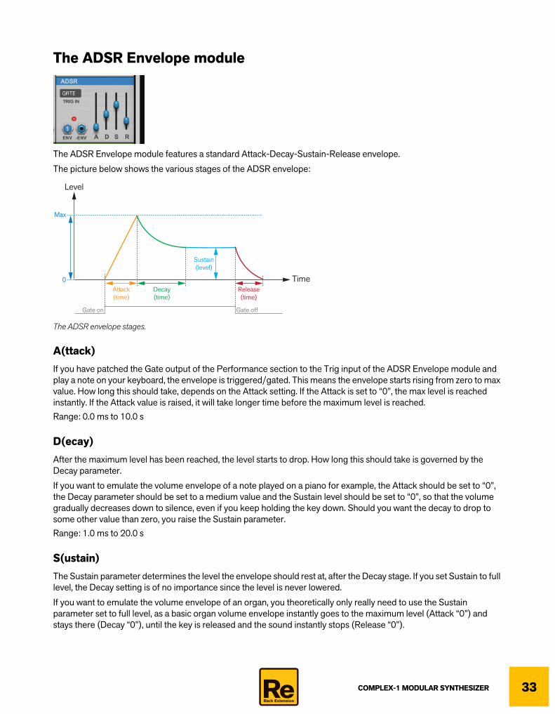
The ADSR Envelope module features a standard Attack-Decay-Sustain-Release envelope.
The picture below shows the various stages of the ADSR envelope:
The ADSR envelope stages.
A(ttack)If you have patched the Gate output of the Performance section to the Trig input of the ADSR Envelope module and play a note on your keyboard, the envelope is triggered/gated. This means the envelope starts rising from zero to max value. How long this should take, depends on the Attack setting. If the Attack is set to “0”, the max level is reached instantly. If the Attack value is raised, it will take longer time before the maximum level is reached.Range: 0.0 ms to 10.0 s
D(ecay)After the maximum level has been reached, the level starts to drop. How long this should take is governed by the Decay parameter.
If you want to emulate the volume envelope of a note played on a piano for example, the Attack should be set to “0”, the Decay parameter should be set to a medium value and the Sustain level should be set to “0”, so that the volume gradually decreases down to silence, even if you keep holding the key down. Should you want the decay to drop to some other value than zero, you raise the Sustain parameter.Range: 1.0 ms to 20.0 s
S(ustain)The Sustain parameter determines the level the envelope should rest at, after the Decay stage. If you set Sustain to full level, the Decay setting is of no importance since the level is never lowered.
If you want to emulate the volume envelope of an organ, you theoretically only really need to use the Sustain parameter set to full level, as a basic organ volume envelope instantly goes to the maximum level (Attack “0”) and stays there (Decay “0”), until the key is released and the sound instantly stops (Release “0”).
Attack(time)
Decay(time)
Sustain(level)
Release(time)
Time
Level
Gate on Gate off
Max
0

COMPLEX-1 MODULAR SYNTHESIZER34
But often a combination of Decay and Sustain is used to generate envelopes that rise up to the maximum level, then gradually decreases to finally land to rest on a level somewhere in-between zero and max level. Note that Sustain represents a level, whereas the other envelope parameters represent times.Range: -inf to 0.0 dB
R(elease)The Release parameter works just like the Decay parameter, except it determines the time it takes for the level to drop back to zero after you release the key.Range: 1.0 ms to 20.0 s
Trig InHere is where you route the trig/gate input signal to the ADSR Envelope module. Each time the envelope is triggered/gated the LED shows the level intensity throughout the envelope stages.
q For more details about the Trig/Gate functions, see “About Trig/Gate and Reset inputs”.
ENV and -ENV outputs• The ENV jack outputs the envelope control signal.
You can patch this output to the Mixer, to control the volume of a Mixer amplifier, for example. You could also patch it to a Filter to control the cutoff frequency over time.
• The -ENV jack outputs the envelope control signal inverted.The control signal is inverted on the negative level side:
Normal (ENV) and inverted (-ENV) envelope curves.
Time
Level
Gate on Gate off Gate on Gate off
Max
+
0
Time
Level
0
_
Min
ENV -ENV

COMPLEX-1 MODULAR SYNTHESIZER 35
The Mix module
The Mix module contains three individual mixers, which lets you mix (sum) two signals each. Each control/modulation input “channel” also features an attenuverter (instead of an attenuator) for controlling the modulation level. The attenuverter outputs zero level at the 12 o’clock position, inverted attenuation to the left and positive attenuation to the right.
• If nothing is connected to In 2, it's "normalled to full", meaning that you can use it for a static control voltage output, positive or negative:
• If only In 2 is connected you can use the attenuverter knob to scale and/or invert the signal:
• If both In signals are bipolar and cyclic you could use it for mixing (summing) the signals.
q To visualize how the signals are affected, use the Oscilloscope and select the desired Mix 1/2/3 output as the signal source to monitor, see “Using the Oscilloscope”.
In 1Here is where you route the audio input signals to the Mix module.
In 2Here is where you route the modulation signals to the Mix module.
D Set the modulation level with the attenuverter knob.Range: -1.00 to +1.00
OutThese are the individual outputs for the mixed/scaled signals.
The Lag module
The Lag module is basically a -12 dB/oct lowpass filter for control signals - and for audio signals. It can be used for smoothing out modulation signals and for creating portamento-like effects from sequencers etc.
KNOB
In 1 signal only Out signal
Level
Time
KNOB
Out signal
Level
Time
KNOB
Out signal
Level
Time
Level
Time
KNOB
In 2 signal only Out signal
Level
Time
KNOB
Out signal
Level
Time
KNOB
Out signal
Level
Time
Level
Time

COMPLEX-1 MODULAR SYNTHESIZER36
InHere is where you route the control/audio signal that should be filtered.
Lag Rate and modulationD Set the lag rate with the Lag Rate knob.
D If desired, select a Lag Rate modulation source from the pop-up menu in the display.When a unipolar source is connected to the modulation input, the Lag Rate knob will set the maximum lag, i.e. what you get when the modulation signal is at its highest level.
! Note that the modulation input delays the modulation input signal slightly (by one sample). This is intentional so that you could create special portamento effects (using the Sequencer module) when modulated from a gate signal.In a sequencer-based patch, if you connect the Gate signal from the sequencer to the Lag modulation input, you can get auto-glide (portamento) on tied notes. There is an example patch showing this - see the “Templates and Examples” patch folder.
OutThis is the outputs for the lagged control signal.
The Scale & Amp module
The Scale & Amp module contains three individual amplifiers, each letting you amplify a signal by multiplying it with another signal.
• If the Level signal is positive unipolar and static you could use it to amplify the In signal like a regular amplifier.
• If the Level signal is positive unipolar and cyclic you could use it for amplitude modulating the In signal.
• If the Level signal is bipolar and cyclic you could use it for ring modulating the In signal.
• If you connect In only, the Amount control will scale that signal (Level input is normalled to full). At Amount 0, out-put will be 0:
• If you connect the Level input only, the output will be (1-Amount)+(Amount x Level input). This means the output will be high when the Amount knob is 0. Raising the Amount knob will gradually increase modulation by the Level input signal:
q To visualize how the signals are affected, use the Oscilloscope and select the desired Amplifier 1/2/3 output as the signal source to monitor, see “Using the Oscilloscope”.
KNOB
In signal only Out signal
Level
Time
KNOB
Out signal
Level
Time
KNOB
Out signal
Level
Time
Level
Time
KNOB
Level signal only Out signal
Level
Time
KNOB
Out signal
Level
Time
KNOB
Out signal
Level
Time
Level
Time

COMPLEX-1 MODULAR SYNTHESIZER 37
InHere is where you route the audio input signals to the Scale & Amp module.
LevelHere is where you route the amp control signals to the Scale & Amp module.
D Attenuate the amplification amount with the Amount knob.Range: 0.00-1.00
OutThese are the individual outputs for the amplified signals.
The Output Mixer module
The Output Mixer module features three channels with their own built-in amplifiers. Each channel can have its own Pan position - and the Pan positions can also be modulated from an external modulation source. The mixed signal output is internally routed to the inputs of the Reverb module, see “The Reverb module”.
In 1/In 2/In 3Here is where you route the audio input signals to the Output Mixer module.
Vol knobsD Set the maximum level (volume) for each channel with the corresponding Volume knob.
Vol modulationHere is where you route the control signals that should control the volume levels of the three channels in the Output Mixer module.
q To control audio signal volumes from an envelope, patch the ADSR Envelope ENV output to the desired Mixer channel Vol Modulation input(s).
q Note that you could also modulate the volume using audio rate signals, e.g. for ring-modulation effects.
PanD Set the panning position for each channel with the corresponding Pan knob.

COMPLEX-1 MODULAR SYNTHESIZER38
Pan modulationHere is where you can route control signals to modulate the Pan positions of channel 1 and 3. The modulation amount control is bipolar, so you could set up inverted panning modulation for channel 1 and 3.
D Attenuate the modulation amounts with the corresponding knobs.
! Note that the channel 2 Pan cannot be modulated - only channel 1 and 3.
The Reverb module
The Reverb module can be used as a “master insert effect” for adding reverb to the Complex-1 output signal. The audio input to the Reverb module is internally routed from the Mixer module outputs (see “The Output Mixer module”) and the output is internally routed to the Master L&R Outs, via the Master Level control. The Reverb module features four reverb and two echo algorithms:
• Spring 1 and Spring 2These simulate electro-mechanical spring reverbs with two different characters.
• RoomThis simulates a room.
• HallThis emulates the ambience of a hall.
• Echo 1This is a reverb with diffuse delay repeats.
• Echo 2This is a reverb with a little less diffuse delay repeats.
On/OffD Click to activate the Reverb module.
Reverb displayD Click in the display and select the desired reverb algorithm.
LevelD Set the dry/wet mix with the Level knob.
DecayD Set the reverb decay time (or delay repeat times) with the Decay knob.

COMPLEX-1 MODULAR SYNTHESIZER 39
The Clock & LFO module
The Clock & LFO module can be used for outputting clock gate/pulse signals with variable length (pulsewidth) and/or an LFO signal with variable shape (saw-triangle-saw). The clock/LFO signals are always synced to the Reason sequencer tempo.
OutThis outputs the positive unipolar clock gate/pulse signals.
WaveThis outputs the LFO control signal (as a continuous bipolar CV signal).
RateThe Clock/LFO rate is always synced to the Reason sequencer tempo.
D Set the Clock/LFO rate (relative to the Reason sequencer tempo) with the Rate knob.Range (synced): 8 bars, 4 bars, 3 bars, 2 bars, 7/4, 6/4, 5/4, 4/4, 3/4, 2/4, 1/4, 3/16, 1/8, 1/8T, 1/16, 1/32, 1/64.
Length/ShapeHere you can set the pulse width of the unipolar Clock signal (which is output on the Out jack, see “Out”) and the shape of the LFO signal (which is output on the Wave output, see “Wave”).
D Modify the Length/Shape continuously as follows:
Clocks Follow Main Sequencer• When this is activated, the Clock and LFO (and Clock 2) starts and stops when you start and stop playback on the
main Reason sequencer.
LENGTH/ SHAPE
Out (Clock) signal Wave (LFO) signal
LENGTH/ SHAPE
LENGTH/ SHAPE
Level
Time
Level
Time
Level
Time
Level
Time
Level
Time
Level
Time

COMPLEX-1 MODULAR SYNTHESIZER40
The Clock 2 module
The Clock 2 module can be used for outputting clock gate/pulse signals with variable length (pulsewidth). The clock signal is always tempo synced (together with the Clock & LFO module) to the Reason sequencer. You could also choose to multiply the clock rate - and modulate the multiplication factor from a selectable source. The Clock 2 can also be activated from an external modulation source.
OnD Click the In display and select a modulation source to activate Clock 2 from the pop-up menu.
Alternatively, switch to “cable mode” and patch a cable from the desired modulation source output to this input.
The Clock 2 signal is activated when the modulation input signal is >0.
If modulated from a bipolar signal source the Clock is activated as described in “About Trig/Gate and Reset inputs”.
Multi displayD Select a modulation source for the “Multi knob”, if desired.
OutThis outputs the positive unipolar clock gate/pulse signals.
Multi knobD Set the multiplication factor between the clock signal and the Rate knob.
Range: 1x, 2x, 4x, 8x and 16x
RateThe Clock 2 rate is always synced to the Reason sequencer tempo.
D Set the Clock/LFO rate (relative to the Reason sequencer tempo) with the Rate knob.Range (synced): 8 bars, 4 bars, 3 bars, 2 bars, 7/4, 6/4, 5/4, 4/4, 3/4, 2/4, 1/4, 3/16, 1/8, 1/8T, 1/16, 1/32, 1/64.
LengthHere you can set the pulse width of the Clock 2 signal (that is output on the Out jack, see “Out”). The pulsewidth characteristics is the same as for Clock 1, see “Length/Shape”.
Clocks Follow Main Sequencer• When this is activated, the Clock and LFO (and Clock 2) starts and stops when you start and stop playback on the
main Reason sequencer.

COMPLEX-1 MODULAR SYNTHESIZER 41
The Sequencer & Note Quantizer module
The Step Sequencer & Note Quantizer module features a flexible step sequencer that can output gate pulses and a CV control signal that you could route to the desired destination(s) in Complex-1. If you like you could also quantize the CV signal values to correspond to the desired note values in a chromatic scale.
Sequencer display
D Click in the upper row to set the last step in the sequence, where the sequencer should start over again.
D Click (or click and hold and drag up/down) on any of the value bars to set CV values for each step.You could also click and hold and drag horizontally to set adjacent values in one go.
D Click the steps you want to send out a gate signal on the Gate output (see “Gate”).Click and hold and drag horizontally to the right to tie adjacent steps into longer steps. Click and hold and drag horizontally to the left to enable/disable several adjacent steps in one go.
! CV values will be sent out also for steps with Gate off.
StepD Select a modulation source that should force the sequencer to advance one step at a time.
When modulated from a bipolar signal source the sequencer will advance one step for every trig pulse as described in “About Trig/Gate and Reset inputs”.
ResetD Select a modulation source that should force the sequencer to restart.
When modulated from a bipolar signal source the sequencer will be restarted with every new trig pulse as described in “About Trig/Gate and Reset inputs”.
GateThis outputs the clock gate/pulse signals from the sequencer - as defined by the red “boxes” in the Sequencer display (see “Sequencer display”).
CurveThis outputs the sequencer control signal (as a continuous CV signal).
Last stepCV values
Active gate steps

COMPLEX-1 MODULAR SYNTHESIZER42
OffsetHere you could add a steady or variable offset to the Note output signal, perfect it you want to “transpose” the Note signal up or down, for example.
D Select a modulation source that should add a value to the Curve signal.The Curve+Offset values are then sent out on the Note output (see below).
NoteThis outputs the sequencer Curve+Offset signal as a continuous CV signal, quantized to the specific note values you have set up in the Keyboard display (see “Keyboard display”).
RangeD Set the desired (note) range for the generated Note output (see above).
Range: 0-84 notes.
Keyboard displayHere you can select if you want the Note output to restrict the output only to certain notes in each octave.
D Click on the notes you want to quantize the Note output to.Selected notes are highlighted in blue.
COMPLEX-1 MODULAR SYNTHESIZER 43
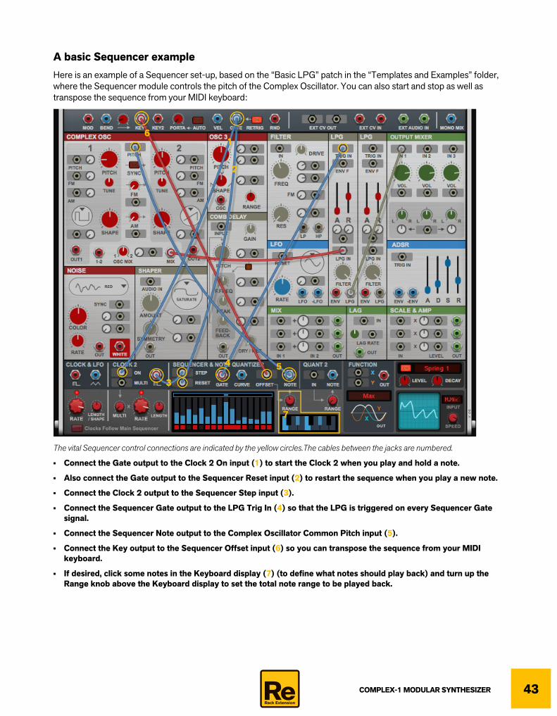
A basic Sequencer exampleHere is an example of a Sequencer set-up, based on the “Basic LPG” patch in the “Templates and Examples” folder, where the Sequencer module controls the pitch of the Complex Oscillator. You can also start and stop as well as transpose the sequence from your MIDI keyboard:
The vital Sequencer control connections are indicated by the yellow circles.The cables between the jacks are numbered.
• Connect the Gate output to the Clock 2 On input (1) to start the Clock 2 when you play and hold a note.
• Also connect the Gate output to the Sequencer Reset input (2) to restart the sequence when you play a new note.
• Connect the Clock 2 output to the Sequencer Step input (3).
• Connect the Sequencer Gate output to the LPG Trig In (4) so that the LPG is triggered on every Sequencer Gate signal.
• Connect the Sequencer Note output to the Complex Oscillator Common Pitch input (5).
• Connect the Key output to the Sequencer Offset input (6) so you can transpose the sequence from your MIDI keyboard.
• If desired, click some notes in the Keyboard display (7) (to define what notes should play back) and turn up the Range knob above the Keyboard display to set the total note range to be played back.
1
2
3
4 5
6
7

COMPLEX-1 MODULAR SYNTHESIZER44
The Quant 2 module
The Quant 2 module is kind of an “extension” to the Sequencer and Note Quantizer module, which you can use for quantizing a CV input signal to the notes you have selected in the keyboard display (see “Keyboard display”) in the Sequencer and Note Quantizer module.
InD Select the input signal you want to quantize.
RangeD Set the desired (note) range for the generated Note output.
Range: 0-84 notes.
NoteThis outputs a continuous CV signal, quantized to the specific note values you have set up in the Keyboard display (see “Keyboard display”).
The Function module
The Function module can be used for performing various mathematical operations on (up to) two input signals and then outputting the resulting signal. The Function module works for any type on signals, including audio signals.
q If you want to visualize the resulting signal, select “Function” as source in the Oscilloscope.
X and Y inputsD Click in the desired display and select a signal source from the pop-up menu.
Alternatively, switch to “cable mode” and patch a cable from the desired signal output to this input.
OutThis is the output for the resulting signal.
D Click and hold on the output jack and then drag to the desired destination and release the mouse button. Alternatively switch to “cable mode” and perform the same operation.
Function selectorD Select the desired function in the Function Selector.

COMPLEX-1 MODULAR SYNTHESIZER 45
The functions are as follows:
• X-Y
This function subtracts the Y value from the X value and outputs the result. If you are only using the Y input, the resulting signal will be an inverted version of the Y values.
• Abs(X+Y)
This function is also known as a full-wave rectifier. It adds the X and Y values and outputs the sum. If the sum is negative, it inverts the result so it becomes positive. This way, the output values are always positive, regardless if the input values are negative. You could use this for generating unipolar control signals out of bipolar LFO signals, for example.
• Min
This function compares the X and Y values and outputs the minimum value. If only one input is connected (or if one of the signals has the value “0”) it works as a half-wave rectifier, which only lets negative signals through. You could use this for generating complex LFO signals out of two different LFO input signals, for example.
• Max
This function compares the X and Y values and outputs the maximum value. If only one input is connected (or if one of the signals has the value “0”) it is a half-wave rectifier, which only lets positive signals through. You could use this for generating complex LFO signals out of two different LFO input signals, for example. You could also use is for merging two gate signals
• X>Y
This is a Comparator, which compares the X and Y values and outputs a positive DC signal when X>Y. When X<Y there is no output. This could be used for extracting a Gate signal when the level of the X signal exceeds the Y signal value, for example.
An interesting application of X>Y is to input an envelope with a long attack (etc) to X and a static positive value (from a Mix module for example) to Y. When the envelope rises past the static value, the output goes high, creating a delayed gate signal. By adjusting the static value (or the envelope attack time), you adjust the delay.
See the "Staggered LPGs" patch in the Templates and Examples patch folder.
OUT
X
Y
OUTX
Y
OUTX
Y
OUTX
Y
=0
OUT
=1X
Y

COMPLEX-1 MODULAR SYNTHESIZER46
• S/H
This is a Sample & Hold function. Patch an audio signal to the Y input and trig the output with another signal (a clock pulse, for example) on the X input. When the “trig” signal is sent, the current value of the Y signal is output.
A typical Sample & Hold application is to input a noise signal on the Y input and a clock/gate signal on the X input, to get stepped random values on the output.
q See “About Trig/Gate and Reset inputs” for more details regarding trig signals.
• Harmonic
This function works on the sum of input X and Y, and only on positive signals. It quantizes an incoming CV value to the natural harmonic series. Connect the output to a Pitch modulation input on an oscillator etc. This way the pitch of the modulated oscillator will jump between the harmonics, which sounds very nice. Another nice application is to connect the output to the Pitch input of an oscillator that is used for FM modulation of another oscillator.
• Pitch
This function is a pitch detector. The pitch is detected from the sum of the X and Y input signals and the detected pitch is sent out as a Note CV value. Patch an external audio signal to the X or Y input and patch the output to a Pitch modulation input on an Oscillator module, for example.
=HOLD
OUT
X
Y
+XY NOTE
CVOUT
X+YNOTECVOUTFREQ

COMPLEX-1 MODULAR SYNTHESIZER 47
Rear panel connections
! Remember that CV connections are NOT stored in the Complex-1 patches! If you want to store CV connections between devices, put them in a Combinator device and save the Combi patch.
Sequencer Control inputsThe Sequencer Control CV and Gate inputs allow you to play Complex-1 from another CV/Gate device (typically a Matrix or an RPG-8). The signal to the CV input controls the note pitch, while the signal to the Gate input delivers note on/off along with velocity. There are also inputs with attenuation knobs for modulating the Pitch Bend and Mod Wheel parameters.
CV Out and InThese control voltage (CV) inputs and outputs can be used for modulation. The signals on the inputs and outputs are then available in the Performance section on the front panel, see “Ext CV In 1&2” and “Ext CV Out 1&2”.

COMPLEX-1 MODULAR SYNTHESIZER48
Audio InHere you can route external audio signals into Complex-1. The signals on these inputs are then available on the Audio Inputs in the Performance section on the front panel, see “Ext Audio In 1&2”.
Master OutThese are the main audio outputs. When you create a new Complex-1 device, these outputs are auto-routed to the first available Mix Channel in the main mixer. If there is no Mix Channel available, a new one will be automatically cre-ated.
Tips & Tricks
Making the ADSR Envelope velocity sensitiveSince there is no dedicated Velocity input on the ADSR module, you will have to patch this yourself. It’s really easy, though:
1. Let’s start by right clicking the front panel and selecting “Reset Device” - and then clicking the “Show Cables” but-ton:
COMPLEX-1 MODULAR SYNTHESIZER 49
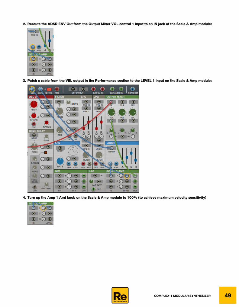
2. Reroute the ADSR ENV Out from the Output Mixer VOL control 1 input to an IN jack of the Scale & Amp module:
3. Patch a cable from the VEL output in the Performance section to the LEVEL 1 input on the Scale & Amp module:
4. Turn up the Amp 1 Amt knob on the Scale & Amp module to 100% (to achieve maximum velocity sensitivity):

COMPLEX-1 MODULAR SYNTHESIZER50
5. Connect OUT 1 of the Scale & Amp module to VOL control 1 of the Output Mixer module:
Making the LPG module velocity sensitiveThis example explains how to make the LPG (Lowpass Gate) module velocity sensitive:
1. Let’s start by loading the patch “Basic LPG” from the “Templates and Examples” folder and then clicking the “Show Cables” button:

COMPLEX-1 MODULAR SYNTHESIZER 51
2. Reroute the Gate output in the Performance section from the LPG Trig In to the IN 1 input on the Scale & Amp module (1). Then, patch a cable from the VEL output in the Performance section to the Level 1 input on the Scale & Amp module (2):
3. Turn up the Amp 1 Amt knob on the Scale & Amp module. 100% will give you achieve maximum velocity sensitivity, so slightly lower might preferable:
4. Connect Output 1 of the Scale & Amp module to the ENV F input on the LPG module:
You now have Velocity control over the LPG filter sweep and amplitude. Use the A and R sliders in the LPG module to set the Attack and Release times. Note that you will also have sustain for as long as you hold the key(s).
12
12

COMPLEX-1 MODULAR SYNTHESIZER52
Creating portamentoThis example shows how you can create a portamento effect, to make the note pitches glide between the keys:
1. Let’s start by right clicking the front panel and selecting “Reset Device” - and then clicking the “Show Cables” but-ton:
2. Reroute the Key1 output in the Performance section from the Pitch input of the Complex Oscillator to the IN jack of the Lag module (1). Then, route the OUT jack of the Lag module back to the Pitch input of the Complex Oscillator (2):
3. Set the portamento rate with the Lag Rate knob:
1
2
1
2
COMPLEX-1 MODULAR SYNTHESIZER 53
About the patches in the “Templates and Examples” folderIn the Complex-1 factory sound bank there is a folder named “Templates and Examples”. This folder contains a number of useful patches that show various routing examples:
Empty (no routings)This is simply a blank slate for when you want to start without any pre-made routings whatsoever.
Alternating valuesIn this patch, the sequencer goes between step 1 and 2 each time you play a note. The sequencer curve is routed to Osc Mix, so you'll alternately hear Oscillator 1 and Oscillator 2 (but of course, this could go to other parameters instead).
Basic DuophonyShows how to connect the Key1 and Key2 jacks to one oscillator each, for "duophonic" playing.
Basic LPGA template showing how to route an oscillator through the LPG, and trigger this from the gate signal.
Classic Sample & HoldUses the S&H function in the Function module. White noise is sent to input Y and Clock 2 is sent to input X - each time a clock signal is received there, the Function module outputs whatever value the incoming noise had at that moment. The result is stepped random, here modulating the filter frequency.Gate is connected to Clock 2 On, so the clock only runs when you play notes.
Harmonic FMOscillator 2 is FM-modulated by Oscillator 1. The pitch of Osc 1 is controlled by the mod wheel, but since the mod wheel signal passes through the "Harmonic" function in the Function module, the Osc 1 pitch will always be a natural overtone - resulting in clean, harmonic FM. The Function signal goes through the Lag module to make the transitions smoother when you move the mod wheel.
q To clearly hear the result of the Harmonic function, turn the Osc Mix knob to Osc 1 and move the mod wheel.
Retriggering EnvThe ADSR envelope will retrigger itself. Changing the Release slider will change how fast the envelope is retriggered. This is done using the X>Y comparator function in the Function module. X gets a signal from Mix1, which is set to a static value, slightly above 0. Y is fed by the Envelope signal. This means that when the envelope signal drops to 0, it goes below the X signal and the Function output goes high, sending a new trigger to the Envelope.
Retriggering LPGAnother way of retriggering, using the LPG and the Mix modules: The Env signal from the LPG goes to Mix 2, where it's offset negatively a slight amount with the attenuverter. This means the Mix2 output drops a little bit below zero when the LPG envelope goes down. This signal is then inverted in Mix 1 - meaning that the signal goes just above zero at the end of the LPG envelope, just enough to be a trigger signal, which is sent back to the LPG Trig In.

COMPLEX-1 MODULAR SYNTHESIZER54
Seq Auto GlideTo hear this you need to press Play in Reason's sequencer. This is a TB-style sequence, where some gates are tied (legato). By routing the Seq Gate output to the Lag Rate modulation input, only tied notes will get lag (portamento), resulting in a typical "auto-glide" effect.
Seq, trig and transposeShows how to trigger a sequence by routing Gate to Clock 2 On and to Sequencer Reset (so that the sequence starts from the beginning each time you play a note). The output of the sequence is first quantized to a C major scale, then transposed by the played key by adding Sequencer Note and Key in the Mix module.
Staggered LPGsIn this patch, Osc 1 and 2 are routed individually through LPG 1 and LPG 2, respectively. When you play a note, you first hear Osc 1, then the detuned Osc 2 slightly later. This is because the trig signal to LPG 2 is delayed. There are several ways to accomplish this, but here we used the X>Y function in the Function module:The Gate triggers the ADSR envelope, with a long attack time. The Env output from the ADSR is connected to Function input X.The Y input is fed with a static positive value from a Mix module (using the attenuverter). When the envelope rises so that the Env signal is higher than the static value, the Function module outputs a high signal, triggering LPG 2. You can adjust the delay time by tweaking the attenuverter on the Mix module (or the ADSR Attack time).
CreditsComplex-1 was designed and developed by Propellerhead Software.
Sound design by: Tom PritchardFlatpack (Ian Duncan & Simon Sherbourne)DivKidDwarfcraftIntellijelPropellerhead
with additional contributions by:PeffSeligKoshdukaiSL4TMNaviRetlavOlive6741EpiGenetikLeoTonalAxisWongoTheSane