complete installation & programming guide · complete installation & programming guide ......
TRANSCRIPT

MYCAR Telematics Communicator
This system must be installed by a professional.
COMPLETE INSTALLATION & PROGRAMMING GUIDE
NOTICEThe manufacturer will accept no responsability for any electrical damage resulting fromimproper installation of this product, be that either damage to the vehicle itself or to theinstalled device. This device must be installed by a certified technician. Please review theInstallation Guide carefully before beginning any work.
EN-20161230-ARev Date: 20161230

2
TABLE OF CONTENTS
Hardware Parts.............................................................................................................3ADS iDatastart HC or VW.........................................................................................4ADS iDatastart BM - BZ.............................................................................................8AKX Autokinetix or OEM.........................................................................................12CrimeStopper...............................................................................................................16Firstech Compustar CM-7200...............................................................................20Firstech Compustar CM-6200..............................................................................24Directed DBALL 2......................................................................................................28Directed 4X10, 5X10..................................................................................................32Fortin Evo-All..............................................................................................................36Fortin Evo-One...........................................................................................................40Reset Procedure.........................................................................................................43

3
AR-3HU
HRN-MCAR-01
HRN-LLRS-01
HRN-DRS-01
HARDWARE PARTS
4
INSTALLATION, WIRING & PROGRAMMING GUIDE
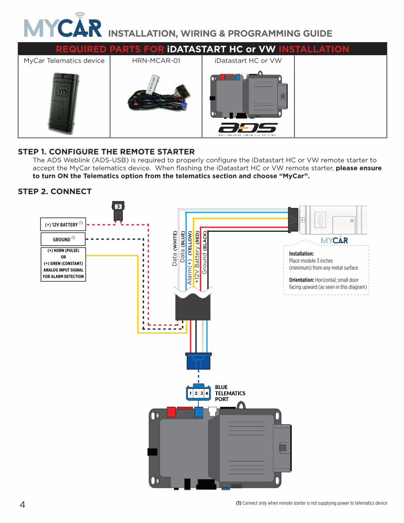
REQUIRED PARTS FOR iDATASTART HC or VW INSTALLATIONMyCar Telematics device HRN-MCAR-01 iDatastart HC or VW
STEP 1. CONFIGURE THE REMOTE STARTERThe ADS Weblink (ADS-USB) is required to properly configure the iDatastart HC or VW remote starter to accept the MyCar telematics device. When flashing the iDatastart HC or VW remote starter, please ensure to turn ON the Telematics option from the telematics section and choose “MyCar”.
STEP 2. CONNECT
3
(+) HORN (PULSE) OR
(+) SIREN (CONSTANT)ANALOG INPUT SIGNAL FOR ALARM DETECTION
(+) 12V BATTERY (1)
GROUND (1)
+12
V B
atte
ry (RED)
Gro
und
(BLA
CK)
Dat
a (W
HITE)
Dat
a (B
LUE)
Ala
rm(+
) (YELL
OW
)
Installation: Place module 3 inches (minimum) from any metal surface
Orientation: Horizontal; small door facing upward (as seen in this diagram)
(1) Connect only when remote starter is not supplying power to telematics device

5
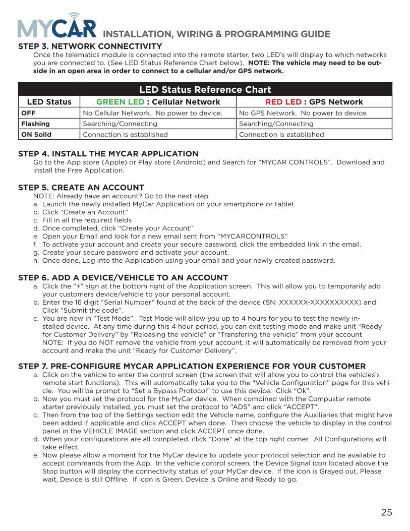
INSTALLATION, WIRING & PROGRAMMING GUIDESTEP 3. NETWORK CONNECTIVITY
Once the telematics module is connected into the remote starter, two LED’s will display to which networks you are connected to. (See LED Status Reference Chart below). NOTE: The vehicle may need to be out-side in an open area in order to connect to a cellular and/or GPS network.
LED Status Reference ChartLED Status GREEN LED : Cellular Network RED LED : GPS Network
OFF No Cellular Network. No power to device. No GPS Network. No power to device.
Flashing Searching/Connecting Searching/Connecting
ON Solid Connection is established Connection is established
STEP 4. INSTALL THE MYCAR APPLICATIONGo to the App store (Apple) or Play store (Android) and Search for “MYCAR CONTROLS”. Download and install the Free Application.
STEP 5. CREATE AN ACCOUNTNOTE: Already have an account? Go to the next step.a. Launch the newly installed MyCar Application on your smartphone or tabletb. Click “Create an Account”c. Fill in all the required fieldsd. Once completed, click “Create your Account”e. Open your Email and look for a new email sent from “MYCARCONTROLS”f. To activate your account and create your secure password, click the embedded link in the email.g. Create your secure password and activate your account.h. Once done, Log into the Application using your email and your newly created password.
STEP 6. ADD A DEVICE/VEHICLE TO AN ACCOUNTa. Click the “+” sign at the bottom right of the Application screen. This will allow you to temporarily add
your customers device/vehicle to your personal account.b. Enter the 16 digit “Serial Number” found at the back of the device (SN: XXXXXX-XXXXXXXXXX) and
Click “Submit the code”.c. You are now in “Test Mode”. Test Mode will allow you up to 4 hours for you to test the newly in-
stalled device. At any time during this 4 hour period, you can exit testing mode and make unit “Ready for Customer Delivery” by “Releasing the vehicle” or “Transfering the vehicle” from your account. NOTE: If you do NOT remove the vehicle from your account, it will automatically be removed from your account and make the unit “Ready for Customer Delivery”.
STEP 7. PRE-CONFIGURE MYCAR APPLICATION EXPERIENCE FOR YOUR CUSTOMERa. Click on the vehicle to enter the control screen (the screen that will allow you to control the vehicles’s
remote start functions). This will automatically take you to the “Vehicle Configuration” page for this vehi-cle. You will be prompt to “Set a Bypass Protocol” to use this device. Click “Ok”.
b. Now you must set the protocol for the MyCar device. When combined with the iDatastart HC remote starter previously installed, you must set the protocol to “ADS” and click “ACCEPT”.
c. Then from the top of the Settings section edit the Vehicle name, configure the Auxiliaries that might have been added if applicable and click ACCEPT when done. Then choose the vehicle to display in the control panel in the VEHICLE IMAGE section and click ACCEPT once done.
d. When your configurations are all completed, click “Done” at the top right corner. All Configurations will take effect.
e. Now please allow a moment for the MyCar device to update your protocol selection and be available to accept commands from the App. In the vehicle control screen, the Device Signal icon located above the Stop button will display the connectivity status of your MyCar device. If the icon is Grayed out, Please wait, Device is still Offline. If icon is Green, Device is Online and Ready to go.

6
INSTALLATION, WIRING & PROGRAMMING GUIDE
STEP 8. TEST YOUR DEVICEOnce in the vehicle control panel and the system is Online you can test the unit. Test all the application func-tions (Start, Stop, Lock, Unlock, Auxiliaries, ETC.) When done with the testing, release or transfer the vehicle from your account to make it “Ready for Customer Delivery”.
Also make sure that the MyCar Owners Card is handed to the Owner of the vehicle. Doing this will ensure that the instructions on how to setup their App, Account and Vehicle is done correctly by using the device serial number located on the sticker affix by the installer at the time of installation

7
INSTALLATION, WIRING & PROGRAMMING GUIDE

8
INSTALLATION, WIRING & PROGRAMMING GUIDE
REQUIRED PARTS FOR iDATASTART BM or BZ INSTALLATIONMyCar Telematics device HRN-MCAR-01 iDatastart BM or BZ
STEP 1. CONFIGURE THE REMOTE STARTERThe ADS Weblink (ADS-USB) is required to properly configure the iDatastart BM or BZ remote starter to ac-cept the MyCar telematics device. When flashing the iDatastart BM or BZ remote starter, please ensure to choose the “Drone” telematics protocol.
STEP 2. CONNECT
(1) Connect only when remote starter is not supplying power to telematics device
3
(+) HORN (PULSE) OR
(+) SIREN (CONSTANT)ANALOG INPUT SIGNAL FOR ALARM DETECTION
(+) 12V BATTERY (1)
GROUND (1)
+12
V B
atte
ry (RED)
Gro
und
(BLA
CK)
Dat
a (W
HITE)
Dat
a (B
LUE)
Ala
rm(+
) (YELL
OW
)
Installation: Place module 3 inches (minimum) from any metal surface
Orientation: Horizontal; small door facing upward (as seen in this diagram)

9
INSTALLATION, WIRING & PROGRAMMING GUIDESTEP 3. NETWORK CONNECTIVITY
Once the telematics module is connected into the remote starter, two LED’s will display to which networks you are connected to. (See LED Status Reference Chart below). NOTE: The vehicle may need to be out-side in an open area in order to connect to a cellular and/or GPS network.
LED Status Reference ChartLED Status GREEN LED : Cellular Network RED LED : GPS Network
OFF No Cellular Network. No power to device. No GPS Network. No power to device.
Flashing Searching/Connecting Searching/Connecting
ON Solid Connection is established Connection is established
STEP 4. INSTALL THE MYCAR APPLICATIONGo to the App store (Apple) or Play store (Android) and Search for “MYCAR CONTROLS”. Download and install the Free Application.
STEP 5. CREATE AN ACCOUNTNOTE: Already have an account? Go to the next step.a. Launch the newly installed MyCar Application on your smartphone or tabletb. Click “Create an Account”c. Fill in all the required fieldsd. Once completed, click “Create your Account”e. Open your Email and look for a new email sent from “MYCARCONTROLS”f. To activate your account and create your secure password, click the embedded link in the email.g. Create your secure password and activate your account.h. Once done, Log into the Application using your email and your newly created password.
STEP 6. ADD A DEVICE/VEHICLE TO AN ACCOUNTa. Click the “+” sign at the bottom right of the Application screen. This will allow you to temporarily add
your customers device/vehicle to your personal account.b. Enter the 16 digit “Serial Number” found at the back of the device (SN: XXXXXX-XXXXXXXXXX) and
Click “Submit the code”.c. You are now in “Test Mode”. Test Mode will allow you up to 4 hours for you to test the newly in-
stalled device. At any time during this 4 hour period, you can exit testing mode and make unit “Ready for Customer Delivery” by “Releasing the vehicle” or “Transfering the vehicle” from your account. NOTE: If you do NOT remove the vehicle from your account, it will automatically be removed from your account and make the unit “Ready for Customer Delivery”.
STEP 7. PRE-CONFIGURE MYCAR APPLICATION EXPERIENCE FOR YOUR CUSTOMERa. Click on the vehicle to enter the control screen (the screen that will allow you to control the vehicles’s
remote start functions). This will automatically take you to the “Vehicle Configuration” page for this vehi-cle. You will be prompt to “Set a Bypass Protocol” to use this device. Click “Ok”.
b. Now you must set the protocol for the MyCar device. When combined with the iDatastart BM or BZ re-mote starter previously installed, you must set the protocol to “ADS” and click “ACCEPT”.
c. Then from the top of the Settings section edit the Vehicle name, configure the Auxiliaries that might have been added if applicable and click ACCEPT when done. Then choose the vehicle to display in the control panel in the VEHICLE IMAGE section and click ACCEPT once done.
d. When your configurations are all completed, click “Done” at the top right corner. All Configurations will take effect.
e. Now please allow a moment for the MyCar device to update your protocol selection and be available to accept commands from the App. In the vehicle control screen, the Device Signal icon located above the Stop button will display the connectivity status of your MyCar device. If the icon is Grayed out, Please wait, Device is still Offline. If icon is Green, Device is Online and Ready to go.
10
INSTALLATION, WIRING & PROGRAMMING GUIDE
STEP 8. TEST YOUR DEVICEOnce in the vehicle control panel and the system is Online you can test the unit. Test all the application func-tions (Start, Stop, Lock, Unlock, Auxiliaries, ETC.) When done with the testing, release or transfer the vehicle from your account to make it “Ready for Customer Delivery”.
Also make sure that the MyCar Owners Card is handed to the Owner of the vehicle. Doing this will ensure that the instructions on how to setup their App, Account and Vehicle is done correctly by using the device serial number located on the sticker affix by the installer at the time of installation

11
INSTALLATION, WIRING & PROGRAMMING GUIDE

12
INSTALLATION, WIRING & PROGRAMMING GUIDE
REQUIRED PARTS FOR AKX or OEM INSTALLATIONMyCar Telematics device HRN-MCAR-01 AKX or OEM
STEP 1. CONFIGURE THE REMOTE STARTERThe ADS Weblink (ADS-USB) is required to properly configure the AKX or OEM remote starter to accept the MyCar telematics device. When flashing the AKX or OEM remote starter, please ensure to choose the “MyCar” telematics protocol.
STEP 2. CONNECT
(1) Connect only when remote starter is not supplying power to telematics device
3
(+) HORN (PULSE) OR
(+) SIREN (CONSTANT)ANALOG INPUT SIGNAL FOR ALARM DETECTION
(+) 12V BATTERY (1)
GROUND (1)
+12
V B
atte
ry (RED)
Gro
und
(BLA
CK)
Dat
a (W
HITE)
Dat
a (B
LUE)
Ala
rm(+
) (YELL
OW
)
Installation: Place module 3 inches (minimum) from any metal surface
Orientation: Horizontal; small door facing upward (as seen in this diagram)

13
INSTALLATION, WIRING & PROGRAMMING GUIDESTEP 3. NETWORK CONNECTIVITY
Once the telematics module is connected into the remote starter, two LED’s will display to which networks you are connected to. (See LED Status Reference Chart below). NOTE: The vehicle may need to be out-side in an open area in order to connect to a cellular and/or GPS network.
LED Status Reference ChartLED Status GREEN LED : Cellular Network RED LED : GPS Network
OFF No Cellular Network. No power to device. No GPS Network. No power to device.
Flashing Searching/Connecting Searching/Connecting
ON Solid Connection is established Connection is established
STEP 4. INSTALL THE MYCAR APPLICATIONGo to the App store (Apple) or Play store (Android) and Search for “MYCAR CONTROLS”. Download and install the Free Application.
STEP 5. CREATE AN ACCOUNTNOTE: Already have an account? Go to the next step.a. Launch the newly installed MyCar Application on your smartphone or tabletb. Click “Create an Account”c. Fill in all the required fieldsd. Once completed, click “Create your Account”e. Open your Email and look for a new email sent from “MYCARCONTROLS”f. To activate your account and create your secure password, click the embedded link in the email.g. Create your secure password and activate your account.h. Once done, Log into the Application using your email and your newly created password.
STEP 6. ADD A DEVICE/VEHICLE TO AN ACCOUNTa. Click the “+” sign at the bottom right of the Application screen. This will allow you to temporarily add
your customers device/vehicle to your personal account.b. Enter the 16 digit “Serial Number” found at the back of the device (SN: XXXXXX-XXXXXXXXXX) and
Click “Submit the code”.c. You are now in “Test Mode”. Test Mode will allow you up to 4 hours for you to test the newly in-
stalled device. At any time during this 4 hour period, you can exit testing mode and make unit “Ready for Customer Delivery” by “Releasing the vehicle” or “Transfering the vehicle” from your account. NOTE: If you do NOT remove the vehicle from your account, it will automatically be removed from your account and make the unit “Ready for Customer Delivery”.
STEP 7. PRE-CONFIGURE MYCAR APPLICATION EXPERIENCE FOR YOUR CUSTOMERa. Click on the vehicle to enter the control screen (the screen that will allow you to control the vehicles’s
remote start functions). This will automatically take you to the “Vehicle Configuration” page for this vehi-cle. You will be prompt to “Set a Bypass Protocol” to use this device. Click “Ok”.
b. Now you must set the protocol for the MyCar device. When combined with the AKX or OEM remote starter previously installed, you must set the protocol to “ADS” and click “ACCEPT”.
c. Then from the top of the Settings section edit the Vehicle name, configure the Auxiliaries that might have been added if applicable and click ACCEPT when done. Then choose the vehicle to display in the control panel in the VEHICLE IMAGE section and click ACCEPT once done.
d. When your configurations are all completed, click “Done” at the top right corner. All Configurations will take effect.
e. Now please allow a moment for the MyCar device to update your protocol selection and be available to accept commands from the App. In the vehicle control screen, the Device Signal icon located above the Stop button will display the connectivity status of your MyCar device. If the icon is Grayed out, Please wait, Device is still Offline. If icon is Green, Device is Online and Ready to go.

14
INSTALLATION, WIRING & PROGRAMMING GUIDE
STEP 8. TEST YOUR DEVICEOnce in the vehicle control panel and the system is Online you can test the unit. Test all the application func-tions (Start, Stop, Lock, Unlock, Auxiliaries, ETC.) When done with the testing, release or transfer the vehicle from your account to make it “Ready for Customer Delivery”.
Also make sure that the MyCar Owners Card is handed to the Owner of the vehicle. Doing this will ensure that the instructions on how to setup their App, Account and Vehicle is done correctly by using the device serial number located on the sticker affix by the installer at the time of installation

15
INSTALLATION, WIRING & PROGRAMMING GUIDE

16
INSTALLATION, WIRING & PROGRAMMING GUIDE
REQUIRED PARTS FOR CrimeStopper INSTALLATIONMyCar Telematics device HRN-MCAR-01 CrimeStopper HRN-LLRS-01
STEP 1. CONFIGURE THE REMOTE STARTERThe CrimeStopper remote starter must be configured to accept the MyCar telematics device. When pro-gramming the CrimeStopper remote starter, please ensure to select the option indicated “Smart Phone Baud Rate”. This option MUST BE SET TO 9600baud.
STEP 2. CONNECT
(1) Connect only when remote starter is not supplying power to telematics device
Compatible models: RS00, RS1, RS3, RS4, RS5,
SP402,SP502
3
(+) HORN (PULSE) OR
(+) SIREN (CONSTANT)ANALOG INPUT SIGNAL FOR ALARM DETECTION
(+) 12V BATTERY (1)
GROUND (1)
+12
V B
atte
ry (RED)
Gro
und
(BLA
CK)
Dat
a (W
HITE)
Dat
a (B
LUE)
Ala
rm(+
) (YELL
OW
)
Installation: Place module 3 inches (minimum) from any metal surface
Orientation: Horizontal; small door facing upward (as seen in this diagram)
HRN-LLRS-01

17
INSTALLATION, WIRING & PROGRAMMING GUIDESTEP 3. NETWORK CONNECTIVITY
Once the telematics module is connected into the remote starter, two LED’s will display to which networks you are connected to. (See LED Status Reference Chart below). NOTE: The vehicle may need to be out-side in an open area in order to connect to a cellular and/or GPS network.
LED Status Reference ChartLED Status GREEN LED : Cellular Network RED LED : GPS Network
OFF No Cellular Network. No power to device. No GPS Network. No power to device.
Flashing Searching/Connecting Searching/Connecting
ON Solid Connection is established Connection is established
STEP 4. INSTALL THE MYCAR APPLICATIONGo to the App store (Apple) or Play store (Android) and Search for “MYCAR CONTROLS”. Download and install the Free Application.
STEP 5. CREATE AN ACCOUNTNOTE: Already have an account? Go to the next step.a. Launch the newly installed MyCar Application on your smartphone or tabletb. Click “Create an Account”c. Fill in all the required fieldsd. Once completed, click “Create your Account”e. Open your Email and look for a new email sent from “MYCARCONTROLS”f. To activate your account and create your secure password, click the embedded link in the email.g. Create your secure password and activate your account.h. Once done, Log into the Application using your email and your newly created password.
STEP 6. ADD A DEVICE/VEHICLE TO AN ACCOUNTa. Click the “+” sign at the bottom right of the Application screen. This will allow you to temporarily add
your customers device/vehicle to your personal account.b. Enter the 16 digit “Serial Number” found at the back of the device (SN: XXXXXX-XXXXXXXXXX) and
Click “Submit the code”.c. You are now in “Test Mode”. Test Mode will allow you up to 4 hours for you to test the newly in-
stalled device. At any time during this 4 hour period, you can exit testing mode and make unit “Ready for Customer Delivery” by “Releasing the vehicle” or “Transfering the vehicle” from your account. NOTE: If you do NOT remove the vehicle from your account, it will automatically be removed from your account and make the unit “Ready for Customer Delivery”.
STEP 7. PRE-CONFIGURE MYCAR APPLICATION EXPERIENCE FOR YOUR CUSTOMERa. Click on the vehicle to enter the control screen (the screen that will allow you to control the vehicles’s
remote start functions). This will automatically take you to the “Vehicle Configuration” page for this vehi-cle. You will be prompt to “Set a Bypass Protocol” to use this device. Click “Ok”.
b. Now you must set the protocol for the MyCar device. When combined with the CrimeStopper remote starter previously installed, you must set the protocol to “ADS” and click “ACCEPT”.
c. Then from the top of the Settings section edit the Vehicle name, configure the Auxiliaries that might have been added if applicable and click ACCEPT when done. Then choose the vehicle to display in the control panel in the VEHICLE IMAGE section and click ACCEPT once done.
d. When your configurations are all completed, click “Done” at the top right corner. All Configurations will take effect.
e. Now please allow a moment for the MyCar device to update your protocol selection and be available to accept commands from the App. In the vehicle control screen, the Device Signal icon located above the Stop button will display the connectivity status of your MyCar device. If the icon is Grayed out, Please wait, Device is still Offline. If icon is Green, Device is Online and Ready to go.

18
INSTALLATION, WIRING & PROGRAMMING GUIDE
STEP 8. TEST YOUR DEVICEOnce in the vehicle control panel and the system is Online you can test the unit. Test all the application func-tions (Start, Stop, Lock, Unlock, Auxiliaries, ETC.) When done with the testing, release or transfer the vehicle from your account to make it “Ready for Customer Delivery”.
Also make sure that the MyCar Owners Card is handed to the Owner of the vehicle. Doing this will ensure that the instructions on how to setup their App, Account and Vehicle is done correctly by using the device serial number located on the sticker affix by the installer at the time of installation

19
INSTALLATION, WIRING & PROGRAMMING GUIDE

20
INSTALLATION, WIRING & PROGRAMMING GUIDE
REQUIRED PARTS FOR Compustar INSTALLATIONMyCar Telematics device HRN-MCAR-01 Compustar CM7200 BLADE-AL (64)
STEP 1. CONFIGURE THE REMOTE STARTERThe ADS Weblink (ADS-USB) is required to properly configure the Compustar remote starter to accept the MyCar telematics device. When flashing the Compustar remote starter, please ensure the remote starter firmware and BLADE-AL (64) firmwares are updated to the latest firmware available.
STEP 2. CONNECT
(1) Connect only when remote starter is not supplying power to telematics device
3
(+) HORN (PULSE) OR
(+) SIREN (CONSTANT)ANALOG INPUT SIGNAL FOR ALARM DETECTION
(+) 12V BATTERY (1)
GROUND (1)
+12
V B
atte
ry (RED)
Gro
un
d (BLA
CK)
Dat
a (W
HITE)
Dat
a (B
LUE)
Ala
rm(+
) (YELL
OW
)
Installation: Place module 3 inches (minimum) from any metal surface
Orientation: Horizontal; small door facing upward (as seen in this diagram)

21
INSTALLATION, WIRING & PROGRAMMING GUIDESTEP 3. NETWORK CONNECTIVITY
Once the telematics module is connected into the remote starter, two LED’s will display to which networks you are connected to. (See LED Status Reference Chart below). NOTE: The vehicle may need to be out-side in an open area in order to connect to a cellular and/or GPS network.
LED Status Reference ChartLED Status GREEN LED : Cellular Network RED LED : GPS Network
OFF No Cellular Network. No power to device. No GPS Network. No power to device.
Flashing Searching/Connecting Searching/Connecting
ON Solid Connection is established Connection is established
STEP 4. INSTALL THE MYCAR APPLICATIONGo to the App store (Apple) or Play store (Android) and Search for “MYCAR CONTROLS”. Download and install the Free Application.
STEP 5. CREATE AN ACCOUNTNOTE: Already have an account? Go to the next step.a. Launch the newly installed MyCar Application on your smartphone or tabletb. Click “Create an Account”c. Fill in all the required fieldsd. Once completed, click “Create your Account”e. Open your Email and look for a new email sent from “MYCARCONTROLS”f. To activate your account and create your secure password, click the embedded link in the email.g. Create your secure password and activate your account.h. Once done, Log into the Application using your email and your newly created password.
STEP 6. ADD A DEVICE/VEHICLE TO AN ACCOUNTa. Click the “+” sign at the bottom right of the Application screen. This will allow you to temporarily add
your customers device/vehicle to your personal account.b. Enter the 16 digit “Serial Number” found at the back of the device (SN: XXXXXX-XXXXXXXXXX) and
Click “Submit the code”.c. You are now in “Test Mode”. Test Mode will allow you up to 4 hours for you to test the newly in-
stalled device. At any time during this 4 hour period, you can exit testing mode and make unit “Ready for Customer Delivery” by “Releasing the vehicle” or “Transfering the vehicle” from your account. NOTE: If you do NOT remove the vehicle from your account, it will automatically be removed from your account and make the unit “Ready for Customer Delivery”.
STEP 7. PRE-CONFIGURE MYCAR APPLICATION EXPERIENCE FOR YOUR CUSTOMERa. Click on the vehicle to enter the control screen (the screen that will allow you to control the vehicles’s
remote start functions). This will automatically take you to the “Vehicle Configuration” page for this vehi-cle. You will be prompt to “Set a Bypass Protocol” to use this device. Click “Ok”.
b. Now you must set the protocol for the MyCar device. When combined with the Compustar remote starter previously installed, you must set the protocol to “ADS” and click “ACCEPT”.
c. Then from the top of the Settings section edit the Vehicle name, configure the Auxiliaries that might have been added if applicable and click ACCEPT when done. Then choose the vehicle to display in the control panel in the VEHICLE IMAGE section and click ACCEPT once done.
d. When your configurations are all completed, click “Done” at the top right corner. All Configurations will take effect.
e. Now please allow a moment for the MyCar device to update your protocol selection and be available to accept commands from the App. In the vehicle control screen, the Device Signal icon located above the Stop button will display the connectivity status of your MyCar device. If the icon is Grayed out, Please wait, Device is still Offline. If icon is Green, Device is Online and Ready to go.

22
INSTALLATION, WIRING & PROGRAMMING GUIDE
STEP 8. TEST YOUR DEVICEOnce in the vehicle control panel and the system is Online you can test the unit. Test all the application func-tions (Start, Stop, Lock, Unlock, Auxiliaries, ETC.) When done with the testing, release or transfer the vehicle from your account to make it “Ready for Customer Delivery”.
Also make sure that the MyCar Owners Card is handed to the Owner of the vehicle. Doing this will ensure that the instructions on how to setup their App, Account and Vehicle is done correctly by using the device serial number located on the sticker affix by the installer at the time of installation

23
INSTALLATION, WIRING & PROGRAMMING GUIDE

24
INSTALLATION, WIRING & PROGRAMMING GUIDE
REQUIRED PARTS FOR Compustar INSTALLATIONMyCar Telematics device HRN-MCAR-01 Compustar CM6200 BLADE-AL (64)
STEP 1. CONFIGURE THE REMOTE STARTERThe ADS Weblink (ADS-USB) is required to properly configure the Compustar remote starter to accept the MyCar telematics device. When flashing the Compustar remote starter, please ensure the remote starter firmware and BLADE-AL (64) firmwares are updated to the latest firmware available.
STEP 2. CONNECT
(1) Connect only when remote starter is not supplying power to telematics device
3
(+) HORN (PULSE) OR
(+) SIREN (CONSTANT)ANALOG INPUT SIGNAL FOR ALARM DETECTION
(+) 12V BATTERY (1)
GROUND (1)
+12
V B
atte
ry (RED)
Gro
und
(BLA
CK)
Dat
a (W
HITE)
Dat
a (B
LUE)
Ala
rm(+
) (YELL
OW
)
Installation: Place module 3 inches (minimum) from any metal surface
Orientation: Horizontal; small door facing upward (as seen in this diagram)
25
INSTALLATION, WIRING & PROGRAMMING GUIDESTEP 3. NETWORK CONNECTIVITY
Once the telematics module is connected into the remote starter, two LED’s will display to which networks you are connected to. (See LED Status Reference Chart below). NOTE: The vehicle may need to be out-side in an open area in order to connect to a cellular and/or GPS network.
LED Status Reference ChartLED Status GREEN LED : Cellular Network RED LED : GPS Network
OFF No Cellular Network. No power to device. No GPS Network. No power to device.
Flashing Searching/Connecting Searching/Connecting
ON Solid Connection is established Connection is established
STEP 4. INSTALL THE MYCAR APPLICATIONGo to the App store (Apple) or Play store (Android) and Search for “MYCAR CONTROLS”. Download and install the Free Application.
STEP 5. CREATE AN ACCOUNTNOTE: Already have an account? Go to the next step.a. Launch the newly installed MyCar Application on your smartphone or tabletb. Click “Create an Account”c. Fill in all the required fieldsd. Once completed, click “Create your Account”e. Open your Email and look for a new email sent from “MYCARCONTROLS”f. To activate your account and create your secure password, click the embedded link in the email.g. Create your secure password and activate your account.h. Once done, Log into the Application using your email and your newly created password.
STEP 6. ADD A DEVICE/VEHICLE TO AN ACCOUNTa. Click the “+” sign at the bottom right of the Application screen. This will allow you to temporarily add
your customers device/vehicle to your personal account.b. Enter the 16 digit “Serial Number” found at the back of the device (SN: XXXXXX-XXXXXXXXXX) and
Click “Submit the code”.c. You are now in “Test Mode”. Test Mode will allow you up to 4 hours for you to test the newly in-
stalled device. At any time during this 4 hour period, you can exit testing mode and make unit “Ready for Customer Delivery” by “Releasing the vehicle” or “Transfering the vehicle” from your account. NOTE: If you do NOT remove the vehicle from your account, it will automatically be removed from your account and make the unit “Ready for Customer Delivery”.
STEP 7. PRE-CONFIGURE MYCAR APPLICATION EXPERIENCE FOR YOUR CUSTOMERa. Click on the vehicle to enter the control screen (the screen that will allow you to control the vehicles’s
remote start functions). This will automatically take you to the “Vehicle Configuration” page for this vehi-cle. You will be prompt to “Set a Bypass Protocol” to use this device. Click “Ok”.
b. Now you must set the protocol for the MyCar device. When combined with the Compustar remote starter previously installed, you must set the protocol to “ADS” and click “ACCEPT”.
c. Then from the top of the Settings section edit the Vehicle name, configure the Auxiliaries that might have been added if applicable and click ACCEPT when done. Then choose the vehicle to display in the control panel in the VEHICLE IMAGE section and click ACCEPT once done.
d. When your configurations are all completed, click “Done” at the top right corner. All Configurations will take effect.
e. Now please allow a moment for the MyCar device to update your protocol selection and be available to accept commands from the App. In the vehicle control screen, the Device Signal icon located above the Stop button will display the connectivity status of your MyCar device. If the icon is Grayed out, Please wait, Device is still Offline. If icon is Green, Device is Online and Ready to go.

26
INSTALLATION, WIRING & PROGRAMMING GUIDE
STEP 8. TEST YOUR DEVICEOnce in the vehicle control panel and the system is Online you can test the unit. Test all the application func-tions (Start, Stop, Lock, Unlock, Auxiliaries, ETC.) When done with the testing, release or transfer the vehicle from your account to make it “Ready for Customer Delivery”.
Also make sure that the MyCar Owners Card is handed to the Owner of the vehicle. Doing this will ensure that the instructions on how to setup their App, Account and Vehicle is done correctly by using the device serial number located on the sticker affix by the installer at the time of installation

27
INSTALLATION, WIRING & PROGRAMMING GUIDE

28
INSTALLATION, WIRING & PROGRAMMING GUIDE
REQUIRED PARTS FOR DBALL2 INSTALLATIONMyCar Telematics device HRN-MCAR-01 DBALL2 HRN-DRS-01
STEP 1. CONFIGURE THE REMOTE STARTERThe Directed XKloader 2 or 3 is required to properly configure the DBALL2 remote starter to accept the MyCar telematics device. When flashing the DBALL2 remote starter, please ensure to choose the “Smart-start” telematics protocol.
STEP 2. CONNECT
(1) Connect only when remote starter is not supplying power to telematics device
3
(+) HORN (PULSE) OR
(+) SIREN (CONSTANT)ANALOG INPUT SIGNAL FOR ALARM DETECTION
(+) 12V BATTERY (1)
GROUND (1)
+12
V B
atte
ry (RED)
Gro
und
(BLA
CK)
Dat
a (W
HITE)
Dat
a (B
LUE)
Ala
rm(+
) (YELL
OW
)
Installation: Place module 3 inches (minimum) from any metal surface
Orientation: Horizontal; small door facing upward (as seen in this diagram)
DBALL 2
HRN-DRS-01

29
INSTALLATION, WIRING & PROGRAMMING GUIDESTEP 3. NETWORK CONNECTIVITY
Once the telematics module is connected into the remote starter, two LED’s will display to which networks you are connected to. (See LED Status Reference Chart below). NOTE: The vehicle may need to be out-side in an open area in order to connect to a cellular and/or GPS network.
LED Status Reference ChartLED Status GREEN LED : Cellular Network RED LED : GPS Network
OFF No Cellular Network. No power to device. No GPS Network. No power to device.
Flashing Searching/Connecting Searching/Connecting
ON Solid Connection is established Connection is established
STEP 4. INSTALL THE MYCAR APPLICATIONGo to the App store (Apple) or Play store (Android) and Search for “MYCAR CONTROLS”. Download and install the Free Application.
STEP 5. CREATE AN ACCOUNTNOTE: Already have an account? Go to the next step.a. Launch the newly installed MyCar Application on your smartphone or tabletb. Click “Create an Account”c. Fill in all the required fieldsd. Once completed, click “Create your Account”e. Open your Email and look for a new email sent from “MYCARCONTROLS”f. To activate your account and create your secure password, click the embedded link in the email.g. Create your secure password and activate your account.h. Once done, Log into the Application using your email and your newly created password.
STEP 6. ADD A DEVICE/VEHICLE TO AN ACCOUNTa. Click the “+” sign at the bottom right of the Application screen. This will allow you to temporarily add
your customers device/vehicle to your personal account.b. Enter the 16 digit “Serial Number” found at the back of the device (SN: XXXXXX-XXXXXXXXXX) and
Click “Submit the code”.c. You are now in “Test Mode”. Test Mode will allow you up to 4 hours for you to test the newly in-
stalled device. At any time during this 4 hour period, you can exit testing mode and make unit “Ready for Customer Delivery” by “Releasing the vehicle” or “Transfering the vehicle” from your account. NOTE: If you do NOT remove the vehicle from your account, it will automatically be removed from your account and make the unit “Ready for Customer Delivery”.
STEP 7. PRE-CONFIGURE MYCAR APPLICATION EXPERIENCE FOR YOUR CUSTOMERa. Click on the vehicle to enter the control screen (the screen that will allow you to control the vehicles’s
remote start functions). This will automatically take you to the “Vehicle Configuration” page for this vehi-cle. You will be prompt to “Set a Bypass Protocol” to use this device. Click “Ok”.
b. Now you must set the protocol for the MyCar device. When combined with the DBALL2 remote starter previously installed, you must set the protocol to “DEI” and click “ACCEPT”.
c. Then from the top of the Settings section edit the Vehicle name, configure the Auxiliaries that might have been added if applicable and click ACCEPT when done. Then choose the vehicle to display in the control panel in the VEHICLE IMAGE section and click ACCEPT once done.
d. When your configurations are all completed, click “Done” at the top right corner. All Configurations will take effect.
e. Now please allow a moment for the MyCar device to update your protocol selection and be available to accept commands from the App. In the vehicle control screen, the Device Signal icon located above the Stop button will display the connectivity status of your MyCar device. If the icon is Grayed out, Please wait, Device is still Offline. If icon is Green, Device is Online and Ready to go.

30
INSTALLATION, WIRING & PROGRAMMING GUIDE
STEP 8. TEST YOUR DEVICEOnce in the vehicle control panel and the system is Online you can test the unit. Test all the application func-tions (Start, Stop, Lock, Unlock, Auxiliaries, ETC.) When done with the testing, release or transfer the vehicle from your account to make it “Ready for Customer Delivery”.
Also make sure that the MyCar Owners Card is handed to the Owner of the vehicle. Doing this will ensure that the instructions on how to setup their App, Account and Vehicle is done correctly by using the device serial number located on the sticker affix by the installer at the time of installation

31
INSTALLATION, WIRING & PROGRAMMING GUIDE

32
INSTALLATION, WIRING & PROGRAMMING GUIDE
REQUIRED PARTS FOR 4X10 - 5X10 INSTALLATIONMyCar Telematics device HRN-MCAR-01 4X10 - 5X10 HRN-DRS-01
STEP 1. CONFIGURE THE REMOTE STARTERThe Directed XKloader 2 or 3 is required to properly configure the 4X10 - 5X10 remote starter to accept the MyCar telematics device. When flashing the 4X10 - 5X10 remote starter, please ensure to choose the “Smartstart” telematics protocol.
STEP 2. CONNECT
(1) Connect only when remote starter is not supplying power to telematics device
3
(+) HORN (PULSE) OR
(+) SIREN (CONSTANT)ANALOG INPUT SIGNAL FOR ALARM DETECTION
(+) 12V BATTERY (1)
GROUND (1)
+12
V B
atte
ry (RED)
Gro
und
(BLA
CK)
Dat
a (W
HITE)
Dat
a (B
LUE)
Ala
rm(+
) (YELL
OW
)
Installation: Place module 3 inches (minimum) from any metal surface
Orientation: Horizontal; small door facing upward (as seen in this diagram)
4X10 - 5X10
HRN-DRS-01

33
INSTALLATION, WIRING & PROGRAMMING GUIDESTEP 3. NETWORK CONNECTIVITY
Once the telematics module is connected into the remote starter, two LED’s will display to which networks you are connected to. (See LED Status Reference Chart below). NOTE: The vehicle may need to be out-side in an open area in order to connect to a cellular and/or GPS network.
LED Status Reference ChartLED Status GREEN LED : Cellular Network RED LED : GPS Network
OFF No Cellular Network. No power to device. No GPS Network. No power to device.
Flashing Searching/Connecting Searching/Connecting
ON Solid Connection is established Connection is established
STEP 4. INSTALL THE MYCAR APPLICATIONGo to the App store (Apple) or Play store (Android) and Search for “MYCAR CONTROLS”. Download and install the Free Application.
STEP 5. CREATE AN ACCOUNTNOTE: Already have an account? Go to the next step.a. Launch the newly installed MyCar Application on your smartphone or tabletb. Click “Create an Account”c. Fill in all the required fieldsd. Once completed, click “Create your Account”e. Open your Email and look for a new email sent from “MYCARCONTROLS”f. To activate your account and create your secure password, click the embedded link in the email.g. Create your secure password and activate your account.h. Once done, Log into the Application using your email and your newly created password.
STEP 6. ADD A DEVICE/VEHICLE TO AN ACCOUNTa. Click the “+” sign at the bottom right of the Application screen. This will allow you to temporarily add
your customers device/vehicle to your personal account.b. Enter the 16 digit “Serial Number” found at the back of the device (SN: XXXXXX-XXXXXXXXXX) and
Click “Submit the code”.c. You are now in “Test Mode”. Test Mode will allow you up to 4 hours for you to test the newly in-
stalled device. At any time during this 4 hour period, you can exit testing mode and make unit “Ready for Customer Delivery” by “Releasing the vehicle” or “Transfering the vehicle” from your account. NOTE: If you do NOT remove the vehicle from your account, it will automatically be removed from your account and make the unit “Ready for Customer Delivery”.
STEP 7. PRE-CONFIGURE MYCAR APPLICATION EXPERIENCE FOR YOUR CUSTOMERa. Click on the vehicle to enter the control screen (the screen that will allow you to control the vehicles’s
remote start functions). This will automatically take you to the “Vehicle Configuration” page for this vehi-cle. You will be prompt to “Set a Bypass Protocol” to use this device. Click “Ok”.
b. Now you must set the protocol for the MyCar device. When combined with the 4X10 - 5X10 remote starter previously installed, you must set the protocol to “DEI” and click “ACCEPT”.
c. Then from the top of the Settings section edit the Vehicle name, configure the Auxiliaries that might have been added if applicable and click ACCEPT when done. Then choose the vehicle to display in the control panel in the VEHICLE IMAGE section and click ACCEPT once done.
d. When your configurations are all completed, click “Done” at the top right corner. All Configurations will take effect.
e. Now please allow a moment for the MyCar device to update your protocol selection and be available to accept commands from the App. In the vehicle control screen, the Device Signal icon located above the Stop button will display the connectivity status of your MyCar device. If the icon is Grayed out, Please wait, Device is still Offline. If icon is Green, Device is Online and Ready to go.

34
INSTALLATION, WIRING & PROGRAMMING GUIDE
STEP 8. TEST YOUR DEVICEOnce in the vehicle control panel and the system is Online you can test the unit. Test all the application func-tions (Start, Stop, Lock, Unlock, Auxiliaries, ETC.) When done with the testing, release or transfer the vehicle from your account to make it “Ready for Customer Delivery”.
Also make sure that the MyCar Owners Card is handed to the Owner of the vehicle. Doing this will ensure that the instructions on how to setup their App, Account and Vehicle is done correctly by using the device serial number located on the sticker affix by the installer at the time of installation

35
INSTALLATION, WIRING & PROGRAMMING GUIDE

36
INSTALLATION, WIRING & PROGRAMMING GUIDE
REQUIRED PARTS FOR EVO-ALL INSTALLATIONMyCar Telematics device HRN-MCAR-01 EVO-ALL HRN-LLRS-01
STEP 1. CONFIGURE THE REMOTE STARTERThe Fortin Flashlink is required to properly configure the EVO-ALL remote starter to accept the MyCar tele-matics device. When flashing the EVO-ALL remote starter, please ensure to choose the following options: “C1 - OEM Remote starter”, “D1 - 3x Lock start”, “H2 - Fortin 2”.
STEP 2. CONNECT
(1) Connect only when remote starter is not supplying power to telematics device
3
(+) HORN (PULSE) OR
(+) SIREN (CONSTANT)ANALOG INPUT SIGNAL FOR ALARM DETECTION
(+) 12V BATTERY (1)
GROUND (1)
+12
V B
atte
ry (RED)
Gro
und
(BLA
CK)
Dat
a (W
HITE)
Dat
a (B
LUE)
Ala
rm(+
) (YELL
OW
)
Installation: Place module 3 inches (minimum) from any metal surface
Orientation: Horizontal; small door facing upward (as seen in this diagram)
HRN-LLRS-01

37
INSTALLATION, WIRING & PROGRAMMING GUIDESTEP 3. NETWORK CONNECTIVITY
Once the telematics module is connected into the remote starter, two LED’s will display to which networks you are connected to. (See LED Status Reference Chart below). NOTE: The vehicle may need to be out-side in an open area in order to connect to a cellular and/or GPS network.
LED Status Reference ChartLED Status GREEN LED : Cellular Network RED LED : GPS Network
OFF No Cellular Network. No power to device. No GPS Network. No power to device.
Flashing Searching/Connecting Searching/Connecting
ON Solid Connection is established Connection is established
STEP 4. INSTALL THE MYCAR APPLICATIONGo to the App store (Apple) or Play store (Android) and Search for “MYCAR CONTROLS”. Download and install the Free Application.
STEP 5. CREATE AN ACCOUNTNOTE: Already have an account? Go to the next step.a. Launch the newly installed MyCar Application on your smartphone or tabletb. Click “Create an Account”c. Fill in all the required fieldsd. Once completed, click “Create your Account”e. Open your Email and look for a new email sent from “MYCARCONTROLS”f. To activate your account and create your secure password, click the embedded link in the email.g. Create your secure password and activate your account.h. Once done, Log into the Application using your email and your newly created password.
STEP 6. ADD A DEVICE/VEHICLE TO AN ACCOUNTa. Click the “+” sign at the bottom right of the Application screen. This will allow you to temporarily add
your customers device/vehicle to your personal account.b. Enter the 16 digit “Serial Number” found at the back of the device (SN: XXXXXX-XXXXXXXXXX) and
Click “Submit the code”.c. You are now in “Test Mode”. Test Mode will allow you up to 4 hours for you to test the newly in-
stalled device. At any time during this 4 hour period, you can exit testing mode and make unit “Ready for Customer Delivery” by “Releasing the vehicle” or “Transfering the vehicle” from your account. NOTE: If you do NOT remove the vehicle from your account, it will automatically be removed from your account and make the unit “Ready for Customer Delivery”.
STEP 7. PRE-CONFIGURE MYCAR APPLICATION EXPERIENCE FOR YOUR CUSTOMERa. Click on the vehicle to enter the control screen (the screen that will allow you to control the vehicles’s
remote start functions). This will automatically take you to the “Vehicle Configuration” page for this vehi-cle. You will be prompt to “Set a Bypass Protocol” to use this device. Click “Ok”.
b. Now you must set the protocol for the MyCar device. When combined with the Evo-All remote starter previously installed, you must set the protocol to “Fortin” and click “ACCEPT”.
c. Then from the top of the Settings section edit the Vehicle name, configure the Auxiliaries that might have been added if applicable and click ACCEPT when done. Then choose the vehicle to display in the control panel in the VEHICLE IMAGE section and click ACCEPT once done.
d. When your configurations are all completed, click “Done” at the top right corner. All Configurations will take effect.
e. Now please allow a moment for the MyCar device to update your protocol selection and be available to accept commands from the App. In the vehicle control screen, the Device Signal icon located above the Stop button will display the connectivity status of your MyCar device. If the icon is Grayed out, Please wait, Device is still Offline. If icon is Green, Device is Online and Ready to go.

38
INSTALLATION, WIRING & PROGRAMMING GUIDE
STEP 8. LEARN THE TELEMATICS DEVICE TO THE EVO-ALLIn order to communicate with the remote starter, the MyCar must be learned to the EVO-ALL. 1 - Disconnect the Black 4 pin power connector from the Evo-All. 2 - Press and Hold the Programming button on the Evo-All while plugging back the Black 4 pin connector. 3 - The LED’s on the Evo-All will begin to cycle. Keep pressing the programming button until the RED and BLUE LED’s are On. 4 - Release the programming button. 5 - Press and Hold the programming button again for 5 seconds. The BLUE and RED LED’s will blink once. 6 - Release the programming button. 7 - Cycle the ignition to the ON position. 8 - The RED, YELLOW and BLUE LED’s will be ON. 9 - Seconds later the RED and BLUE LED’s will blink once to confirm that the MyCar ID has been learned to the Evo-All. 10 - Cycle the vehicle’s ignition to the OFF position to Exit EVO-ALL programming.
STEP 9. TEST YOUR DEVICEOnce in the vehicle control panel and the system is Online you can test the unit. Test all the application func-tions (Start, Stop, Lock, Unlock, Auxiliaries, ETC.) When done with the testing, release or transfer the vehicle from your account to make it “Ready for Customer Delivery”.
Also make sure that the MyCar Owners Card is handed to the Owner of the vehicle. Doing this will ensure that the instructions on how to setup their App, Account and Vehicle is done correctly by using the device serial number located on the sticker affix by the installer at the time of installation

39
INSTALLATION, WIRING & PROGRAMMING GUIDE

40
INSTALLATION, WIRING & PROGRAMMING GUIDE
REQUIRED PARTS FOR EVO-ONE INSTALLATIONMyCar Telematics device HRN-MCAR-01 EVO-ONE HRN-LLRS-01
STEP 1. CONFIGURE THE REMOTE STARTERThe Fortin Flashlink is required to properly configure the EVO-ONE remote starter to accept the MyCar tele-matics device. When flashing the EVO-ONE remote starter, please ensure to choose the following options: Toggle your Flashlink connection mode to “Remote-Starter”. From the top menu click on “Configura-tion” and then on “Unit Options”. In the “RF Kit Compatible” section, check the box next to “Fortin 2” and click the save button on the top right of the screen.
STEP 2. CONNECT
(1) Connect only when remote starter is not supplying power to telematics device
3
(+) HORN (PULSE) OR
(+) SIREN (CONSTANT)ANALOG INPUT SIGNAL FOR ALARM DETECTION
(+) 12V BATTERY (1)
GROUND (1)
+12
V B
atte
ry (RED)
Gro
und
(BLA
CK)
Dat
a (W
HITE)
Dat
a (B
LUE)
Ala
rm(+
) (YELL
OW
)
Installation: Place module 3 inches (minimum) from any metal surface
Orientation: Horizontal; small door facing upward (as seen in this diagram)
HRN-LLRS-01

41
INSTALLATION, WIRING & PROGRAMMING GUIDESTEP 3. NETWORK CONNECTIVITY
Once the telematics module is connected into the remote starter, two LED’s will display to which networks you are connected to. (See LED Status Reference Chart below). NOTE: The vehicle may need to be out-side in an open area in order to connect to a cellular and/or GPS network.
LED Status Reference ChartLED Status GREEN LED : Cellular Network RED LED : GPS Network
OFF No Cellular Network. No power to device. No GPS Network. No power to device.
Flashing Searching/Connecting Searching/Connecting
ON Solid Connection is established Connection is established
STEP 4. INSTALL THE MYCAR APPLICATIONGo to the App store (Apple) or Play store (Android) and Search for “MYCAR CONTROLS”. Download and install the Free Application.
STEP 5. CREATE AN ACCOUNTNOTE: Already have an account? Go to the next step.a. Launch the newly installed MyCar Application on your smartphone or tabletb. Click “Create an Account”c. Fill in all the required fieldsd. Once completed, click “Create your Account”e. Open your Email and look for a new email sent from “MYCARCONTROLS”f. To activate your account and create your secure password, click the embedded link in the email.g. Create your secure password and activate your account.h. Once done, Log into the Application using your email and your newly created password.
STEP 6. ADD A DEVICE/VEHICLE TO AN ACCOUNTa. Click the “+” sign at the bottom right of the Application screen. This will allow you to temporarily add
your customers device/vehicle to your personal account.b. Enter the 16 digit “Serial Number” found at the back of the device (SN: XXXXXX-XXXXXXXXXX) and
Click “Submit the code”.c. You are now in “Test Mode”. Test Mode will allow you up to 4 hours for you to test the newly in-
stalled device. At any time during this 4 hour period, you can exit testing mode and make unit “Ready for Customer Delivery” by “Releasing the vehicle” or “Transfering the vehicle” from your account. NOTE: If you do NOT remove the vehicle from your account, it will automatically be removed from your account and make the unit “Ready for Customer Delivery”.
STEP 7. PRE-CONFIGURE MYCAR APPLICATION EXPERIENCE FOR YOUR CUSTOMERa. Click on the vehicle to enter the control screen (the screen that will allow you to control the vehicles’s
remote start functions). This will automatically take you to the “Vehicle Configuration” page for this vehi-cle. You will be prompt to “Set a Bypass Protocol” to use this device. Click “Ok”.
b. Now you must set the protocol for the MyCar device. When combined with the Evo-All remote starter previously installed, you must set the protocol to “Fortin” and click “ACCEPT”.
c. Then from the top of the Settings section edit the Vehicle name, configure the Auxiliaries that might have been added if applicable and click ACCEPT when done. Then choose the vehicle to display in the control panel in the VEHICLE IMAGE section and click ACCEPT once done.
d. When your configurations are all completed, click “Done” at the top right corner. All Configurations will take effect.
e. Now please allow a moment for the MyCar device to update your protocol selection and be available to accept commands from the App. In the vehicle control screen, the Device Signal icon located above the Stop button will display the connectivity status of your MyCar device. If the icon is Grayed out, Please wait, Device is still Offline. If icon is Green, Device is Online and Ready to go.

42
INSTALLATION, WIRING & PROGRAMMING GUIDE
STEP 8. LEARN THE TELEMATICS DEVICE TO THE EVO-ONEIn order to communicate with the remote starter, the MyCar must be learned to the EVO-ONE. 1 - Cycle the ignition to the ON position. 2 - The YELLOW LED on top of the EVO-ONE should come ON. 3 - Press and Hold the EVO-ONE push button for 5 seconds. 4 - The parking lights and the RED LED on the side of the EVO-ONE will turn ON. 5 - Release the push button. 6 - Press and Release the push button 5x times. Everytime the push button is pressed the parking lights and the RED Led on the side of the EVO-ONE will blink. 7 - Then Press and Release the Brake pedal. 8 - Seconds later the RED LED on the side of the EVO-ONE will blink once to confirm that the MyCar ID has been learned to the EVO-ONE. 9 - Cycle the vehicle’s ignition to the OFF position to Exit the EVO-ONE programming.
STEP 9. TEST YOUR DEVICEOnce in the vehicle control panel and the system is Online you can test the unit. Test all the application func-tions (Start, Stop, Lock, Unlock, Auxiliaries, ETC.) When done with the testing, release or transfer the vehicle from your account to make it “Ready for Customer Delivery”.
Also make sure that the MyCar Owners Card is handed to the Owner of the vehicle. Doing this will ensure that the instructions on how to setup their App, Account and Vehicle is done correctly by using the device serial number located on the sticker affix by the installer at the time of installation.

43
INSTALLATION, WIRING & PROGRAMMING GUIDE
RESET PROCEDURE 1 - Disconnect the main harness from the MyCar device. 2 - Wait approximately 10 seconds and reconnect the main harness to the MyCar device. 3 - This will complete the reset procedure.

© 2016 MyCar Controls. All rights reserved. 400 Wright - St-Laurent, Quebec, H4N1M6 - CANADA