compendium of structural testing data for 20-psi coal mine ...ic 9515 information circular/2009...
TRANSCRIPT

IC 9515 INFORMATION CIRCULAR/2009
Compendium of Structural Testing Data for 20-psi Coal Mine Seals
Department of Health and Human Services
Centers for Disease Control and Prevention
National Institute for Occupational Safety and Health

Information Circular 9515
Compendium of Structural Testing Data for 20-psi Coal Mine Seals
By R. Karl Zipf, Jr., Ph.D., P.E., Eric S. Weiss, Samuel P. Harteis, P.E., and Michael J. Sapko
DEPARTMENT OF HEALTH AND HUMAN SERVICES Centers for Disease Control and Prevention
National Institute for Occupational Safety and Health Pittsburgh Research Laboratory
Pittsburgh, PA
August 2009

This document is in the public domain and may be freely copied or reprinted.
Disclaimer
Mention of any company or product does not constitute endorsement by the National Institute for Occupational Safety and Health (NIOSH). In addition, citations to Web sites external to NIOSH do not constitute NIOSH endorsement of the sponsoring organizations or their programs or products. Furthermore, NIOSH is not responsible for the content of these Web sites. All Web addresses referenced in this document were accessible as of the publication date.
Ordering Information
To receive documents or other information about occupational safety and health topics, contact NIOSH at
Telephone: 1–800–CDC–INFO (1–800–232–4636) TTY: 1–888–232–6348 e-mail: [email protected]
or visit the NIOSH Web site at www.cdc.gov/niosh.
For a monthly update on news at NIOSH, subscribe to NIOSH eNews by visiting www.cdc.gov/niosh/eNews.
DHHS (NIOSH) Publication No. 2009–151
August 2009
SAFER • HEALTHIER • PEOPLE™

CONTENTS Page
Abstract ............................................................................................................................................1 Introduction......................................................................................................................................2 Experimental mine and test procedures ...........................................................................................5 Lake Lynn experimental mine (LLEM)..................................................................................5 Explosion tests in the LLEM ..................................................................................................6 Hydrostatic chamber tests in the LLEM .................................................................................7 Instrumentation and data collection .................................................................................................8 Pressure waves from test explosions.......................................................................................8 Pressure and displacement measurement locations ................................................................9 Loading conditions for seal tests...........................................................................................10 Boundary conditions for seal tests ........................................................................................11 Response times, time constants, and frequency responses for sensors used in the LLEM .....11 Data acquisition system characteristics ................................................................................16 Quality of pressure-time and displacement-time measurements ..........................................17 Adequacy of pressure-time and displacement-time measurements for structural analysis .....20 Comments on smoothing ......................................................................................................21 General construction details for category 1 through 6 seals ..........................................................21 Category 1 seals: concrete or concretelike materials with internal steel reinforcement and anchorage to rock .......................................................................................................21 Category 2 seals: pumpable cementitious materials with no steel reinforcement and no hitching ........................................................................................................................27 Category 3 seals: articulated structures – solid and hollow-core concrete blocks with or without hitching............................................................................................................30 Category 4 seals: polymer and aggregate materials without hitching ..................................38 Category 5 seals: wood-crib-block seals with or without hitching ......................................40 Category 6 seals: articulated structures – lightweight blocks with or without hitching.......45 Structural testing data for 20-psi coal mine seals ..........................................................................49 Summary and conclusions .............................................................................................................57 References......................................................................................................................................58 Appendix.—Detailed summary of seal structure tests and test data..............................................60
ILLUSTRATIONS
1. Plan view of the Lake Lynn experimental mine (LLEM)...........................................................5 2. Plan view of the LLEM showing the multiple-entry area and the seal and stopping
locations ..................................................................................................................................6 3. Schematic of the hydrostatic chamber ........................................................................................7 4. Schematic of pressure and displacement measurement points for typical explosion tests
in the LLEM............................................................................................................................9 5. Dimensionless response function for instantaneous unit step input .........................................12 6. Calculated pressure response for instantaneous 100-psi step input ..........................................13 7. Calculated pressure response for instantaneous 300-psi step input ..........................................14 8. Calculated displacement response for instantaneous 6-in step input (10-ms response time) ......15 9. Calculated displacement response for instantaneous 6-in step input (75-ms response time) ......16

CONTENTS—Continued Page
10. Typical P-t and D-t data for the entire duration of an explosion test in the LLEM................17 11. Expanded time-scale view of P-t data from two separate pressure transducers .....................18 12. Expanded time-scale view of P-t data from the same pressure transducer recorded with separate data acquisition systems operating at 1,500 and 5,000 samples per second.........18 13. Expanded time-scale view of D-t data from the same displacement transducer recorded with separate data acquisition systems operating at 1,500 and 5,000 samples per
second .................................................................................................................................19 14. Computed D-t responses for hypothetical structure using P-t curves in Figure 12 as
input for structural analysis.................................................................................................20 15. Front-, plan-, and side-view drawings of category 1A structure: Insteel 3-D seal from Precision Mine Repair, Inc. ................................................................................................22 16. Detailed plan-view drawing of category 1A structure: Insteel 3-D seal from Precision
Mine Repair, Inc. ................................................................................................................23 17. Closeup of a rear Insteel panel with Stayform backing and the horizontal #3 steel reinforcement bars ..............................................................................................................23 18. Insteel 3-D seal under construction showing the rear Insteel panel with stayform backing, one plane of vertical #8 steel reinforcement bars and anchors, the horizontal #8 steel reinforcement bar anchors, and the horizontal #3 steel reinforcement bars .......................24 19. Insteel 3-D seal under construction with the addition of the front Insteel panel and the front plane of vertical #8 steel reinforcement bars .............................................................25 20. Front-, plan-, and side-view drawings of category 1B structure: Meshblock seal from
R. G. Johnson Co., Inc. .......................................................................................................26 21. Closeup of Meshblock seal under construction showing the Meshblocks and the vertical #8 steel reinforcement bars and anchors.............................................................................27 22. Meshblock seal under construction showing the lower Meshblocks, the vertical #8 steel reinforcement bars and anchors, and placement of shotcrete .............................................27 23. Front-, plan-, and side-view drawings of category 2 structure made from pumpable cementitious materials with no steel reinforcement and no hitching..................................28 24. Formwork for a typical pumpable seal showing the vertical posts, the horizontal boards, and the brattice liner (partially removed)............................................................................29 25. Inside the formwork of a typical pumpable seal showing the brattice liner and the cementitious filling material ...............................................................................................29 26. Front-, plan-, and side-view drawings of category 3A structure: standard solid-concrete-
block seal with simulated hitching......................................................................................31 27. Solid-concrete-block seal under construction showing the center pilaster and the fully mortared joints on all sides .................................................................................................32 28. In background, top of a solid-concrete-block seal showing small cut blocks and mortar filling at the seal top............................................................................................................32 29. Completed solid-concrete-block seal without a center pilaster showing the angle iron
hitch on the ribs and floor only ...........................................................................................33 30. Front-, plan-, and side-view drawings of category 3B structure: solid-concrete-block seal
with Packsetter bags............................................................................................................34

CONTENTS—Continued Page
31. Tongue-and-groove, solid-concrete-block seal with center pilaster using pressurized Packsetter grout bags in lieu of hitching around the seal perimeter ...................................35 32. Front-, plan-, and side-view drawings of category 3C structure: solid- or hollow-core
concrete block ventilation stoppings...................................................................................36 33. Dry-stacked concrete block stopping showing wedges used to fit the stopping to ribs and small cut blocks and a wood plank at the top .....................................................................37 34. Dry-stacked concrete block stopping showing application of an approved sealant to the
surface .................................................................................................................................37 35. Front-, plan-, and side-view drawings of category 4 structure: polymer and aggregate seal ....38 36. Polymer and aggregate seal from MICON showing the rear dry-stacked, hollow-core concrete block wall, the partially completed front wall, a polymer coating on the inside surface of the form walls, and an approved sealant on the outside surface of the form wall.............................................................................................................................39 37. Polymer and aggregate seal from MICON showing the rear and front form wall, the polymer coating on the inner surfaces of the form walls, and the polyurethane foam and aggregate mixture filling the inner core of the seal......................................................40 38. Front-, plan-, and side-view drawings of category 5A structure: wood-crib-block seal with plywood facing and simulated hitching ......................................................................41 39. Closeup of a hitched wood-crib-block seal showing the layer of rock dust placed between each layer of wood crib blocks .............................................................................41 40. Construction of a hitched wood-crib-block seal without plywood facing showing the wood crib blocks separated by a rock dust layer, the angle iron hitching around the ribs and floor only, and the final coating with an approved sealant ...................................42 41. Front-, plan-, and side-view drawings of category 5B structure: wood-crib-block seal
with Packsetter bags............................................................................................................43 42. Construction of a wood-crib-block seal with pressurized Packsetter grout bags in lieu of hitching showing the application of glue between all wood-crib-block surfaces...............44 43. Construction of a wood-crib-block seal with pressurized Packsetter grout bags in lieu of hitching showing the glued wood crib blocks and the grout bags used along the roof
and ribs................................................................................................................................44 44. Front-, plan-, and side-view drawings of category 6A structure: lightweight block seal,
24 in thick with hitching .....................................................................................................46 45. Construction of a 24-in-thick Omega block seal with hitching and a center pilaster .............46 46. Construction of an Omega block seal showing the wood board and wedges used to secure
the seal at the roof ...............................................................................................................47 47. Completed 24-in-thick Omega block seal showing the angle iron hitch along the ribs and floor and the outer surface coated with an approved sealant .......................................47 48. Front-, plan-, and side-view drawings of category 6B structure: lightweight block seal,
40 in thick without hitching ................................................................................................48 49. Construction of a 40-in-thick Omega block seal without hitching and no center pilaster......49
CONTENTS—Continued Page
A-1. Category 1A - structure #1 - test 1 - static, nonuniform loading; Insteel 3-D seal -
shotcrete with reinforcement - LLEM test #419.............................................................80 A-2. Category 1A - structure #2 - test 1 - static, nonuniform loading; Insteel 3-D seal -
shotcrete with reinforcement - LLEM test #419.............................................................80 A-3. Category 1A - structure #3 - test 1 - static, nonuniform loading; Insteel 3-D seal -
shotcrete with reinforcement - LLEM test #419.............................................................81 A-4. Category 1A - structure #4 - test 1 - static, nonuniform loading; Insteel 3-D seal -
shotcrete with reinforcement - LLEM test #420.............................................................81 A-5. Category 1A - structure #5 - test 1 - static, nonuniform loading; Insteel 3-D seal -
shotcrete with reinforcement - LLEM test #420.............................................................82 A-6. Category 1A - structure #6 - test 1 - static, nonuniform loading; Insteel 3-D seal -
shotcrete with reinforcement - LLEM test #420.............................................................82 A-7. Category 1A - structure #7 - test 1 - static, uniform loading; Insteel 3-D seal -
shotcrete with reinforcement - PR-1 ...............................................................................83 A-8. Category 1B - structure #1 - tests 1 to 4 - static, nonuniform loading; Meshblock seal -
shotcrete with reinforcement - LLEM tests #347–350 ...................................................83 A-9. Category 1B - structure #1 - tests 5 to 8 - static, nonuniform loading; Meshblock seal -
shotcrete with reinforcement - LLEM tests #351–358 ...................................................84 A-10. Category 1B - structure #1 - tests 9 to 12 - static, nonuniform loading; Meshblock seal - shotcrete with reinforcement - LLEM tests #359–362 ...................................................84 A-11. Category 1B - structure #1 - tests 13 to 16 - static, nonuniform loading; Meshblock seal - shotcrete with reinforcement - LLEM tests #363–366..........................................85 A-12. Category 1B - structure #2 - tests 1 to 3 - static, nonuniform loading; Meshblock seal - shotcrete with reinforcement - LLEM tests #347–349 ...................................................85 A-13. Category 1B - structure #2 - tests 4 and 5 - static, nonuniform loading; Meshblock seal - shotcrete with reinforcement - LLEM tests #350–351..........................................86 A-14. Category 1B - structure #3 - tests 1 to 3 - static, nonuniform loading; Meshblock seal - shotcrete with reinforcement - LLEM tests #347–349..........................................86 A-15. Category 1B - structure #4 - tests 1 and 2 - static, nonuniform loading; Meshblock seal - shotcrete with reinforcement - LLEM tests #347–348..........................................87 A-16. Category 1B - structure #5 - tests 1 and 2. Meshblock seal - shotcrete with reinforce- ment - LLEM tests #347–348 .........................................................................................87 A-17. Category 1B - structure #6 - tests 1 and 2 - static, nonuniform loading; Meshblock seal - shotcrete with reinforcement - LLEM tests #350–351 ...................................................88 A-18. Category 2A - structure #1 - test 1 - reflected, uniform loading; pumpable 48 in -
LLEM test #508 ..............................................................................................................88 A-19. Category 2A - structure #1 - test 2 - reflected, uniform loading; pumpable 48 in -
LLEM test #509 ..............................................................................................................89 A-20. Category 2A - structure #2 - test 1 - static, uniform loading; pumpable 48 in - test
C3-44E ............................................................................................................................89 A-21. Category 2A - structure #3 - test 1 - static, uniform loading; pumpable 48 in - test
C7-64W...........................................................................................................................90

CONTENTS—Continued Page
A-22. Category 2A - structure #3 - test 2 - static, uniform loading; pumpable 48 in - test
C7-68W...........................................................................................................................90 A-23. Category 2A - structure #3 - test 3 - static, uniform loading; pumpable 48 in - test
C7-70W...........................................................................................................................91 A-24. Category 2A - structure # 4 - test 1 - static, uniform loading; pumpable 48 in - test
L2-51E ............................................................................................................................91 A-25. Category 2B - structure #1 - tests 1 and 2 - static, nonuniform loading; pumpable 36 in -
LLEM tests #354–355.....................................................................................................92 A-26. Category 2C - structure #1 - tests 1 and 2 - static, nonuniform loading; pumpable 24 in -
LLEM tests #354–355.....................................................................................................92 A-27. Category 2C - structure #2 - tests 1 and 2 - static, nonuniform loading; pumpable 24 in -
LLEM tests #354–355.....................................................................................................93 A-28. Category 2C - structure #3 - tests 1 and 2 - static, nonuniform loading; pumpable 24 in -
LLEM tests #354–355.....................................................................................................93 A-29. Category 2C - structure #4 - test 1 - static, nonuniform loading; pumpable 24 in -
LLEM test #403 ..............................................................................................................94 A-30. Category 2C - structure #4 - test 2 - static, nonuniform loading; pumpable 24 in -
LLEM test #404 ..............................................................................................................94 A-31. Category 2C - structure #4 - test 3 - static, nonuniform loading; pumpable 24 in -
LLEM test #405 ..............................................................................................................95 A-32. Category 2C - structure #4 - test 4 - static, nonuniform loading; pumpable 24 in -
LLEM test #406 ..............................................................................................................95 A-33. Category 3A - structure #1 - test 1 - static, nonuniform loading; standard solid- concrete-block seal - LLEM test #403............................................................................96 A-34. Category 3A - structure #1 - test 2 - static, nonuniform loading; standard solid- concrete-block seal - LLEM test #404............................................................................96 A-35. Category 3A - structure #1 - test 3 - static, nonuniform loading; standard solid- concrete-block seal - LLEM test #405............................................................................97 A-36. Category 3A - structure #1 - test 4 - static, nonuniform loading; standard solid- concrete-block seal - LLEM test #406............................................................................97 A-37. Category 3A - structure #2 - tests 1 to 6 - static, nonuniform loading; standard solid- concrete-block seal - LLEM tests #500–505 ..................................................................98 A-38. Category 3A - structure #2 - tests 7 to 10 - static, nonuniform loading; standard solid- concrete-block seal - LLEM tests #506–509 ..................................................................98 A-39. Category 3A - structure #3 - test 1 - static, nonuniform loading; standard solid- concrete-block seal - LLEM test #506............................................................................99 A-40. Category 3A - structure #3 - test 2 - static, nonuniform loading; standard solid- concrete-block seal - LLEM test #507............................................................................99 A-41. Category 3A - structure #4 - test 1 - static, uniform loading; standard solid-concrete-
block seal - test C1-5E ..................................................................................................100 A-42. Category 3A - structure #4 - test 2 - static, uniform loading; standard solid-concrete-
block seal - test C1-8E ..................................................................................................100

CONTENTS—Continued Page
A-43. Category 3A - structure #4 - test 3 - static, uniform loading; standard solid-concrete-
block seal - test C1-9E ..................................................................................................101 A-44. Category 3A - structure #4 - test 4 - static, uniform loading; standard solid-concrete-
block seal - test C1-10E ................................................................................................101 A-45. Category 3A - structure #4 - test 5 - static, uniform loading; standard solid-concrete-
block seal - test C1-11E ................................................................................................102 A-46. Category 3A - structure #5 - test 1 - static, uniform loading; standard solid-concrete-
block seal - test C6-60W...............................................................................................102 A-47. Category 3A - structure #5 - test 2 - static, uniform loading; standard solid-concrete-
block seal - test C6-62E ................................................................................................103 A-48. Category 3A - structure #6 - test 1 - static, uniform loading; standard solid-concrete-
block seal - test L1-37E ................................................................................................103 A-49. Category 3A - structure #7 - test 1 - static, uniform loading; standard solid-concrete-
block seal - test SRCM 1 ..............................................................................................104 A-50. Category 3B - structure #1 - test 1 - static, nonuniform loading; solid-concrete-block seal with Packsetter bags - LLEM test #365.................................................................104 A-51. Category 3B - structure #2 - tests 1 and 2 - static, nonuniform loading; solid-concrete- block seal with Packsetter bags - LLEM tests #365–366 .............................................105 A-52. Category 3B - structure #3 - tests 1 and 2 - static, nonuniform loading; solid-concrete- block seal with Packsetter bags - LLEM tests #365–366 .............................................105 A-53. Category 3C - structure #1 - test 1 - static, nonuniform loading; hollow-core concrete- block ventilation stopping - LLEM test #427...............................................................106 A-54. Category 3C - structure #1 - test 2 - static, nonuniform loading; hollow-core concrete- block ventilation stopping - LLEM test #428...............................................................106 A-55. Category 3C - structure #2 - test 1 - static, nonuniform loading; hollow-core concrete- block ventilation stopping - LLEM test #427...............................................................107 A-56. Category 3C - structure #2 - test 2 - static, nonuniform loading; hollow-core concrete- block ventilation stopping - LLEM test #428...............................................................107 A-57. Category 3C - structure #3 - test 1 - static, nonuniform loading; hollow-core concrete- block ventilation stopping - LLEM test #427...............................................................108 A-58. Category 3C - structure #3 - test 2 - static, nonuniform loading; hollow-core concrete- block ventilation stopping - LLEM test #428...............................................................108 A-59. Category 3C - structure #3 - test 3 - static, nonuniform loading; hollow-core concrete- block ventilation stopping - LLEM test #429...............................................................109 A-60. Category 3C - structure #3 - test 4 - static, nonuniform loading; hollow-core concrete- block ventilation stopping - LLEM test #430...............................................................109 A-61. Category 3C - structure #3 - test 5 - static, nonuniform loading; hollow-core concrete- block ventilation stopping - LLEM test #432...............................................................110 A-62. Category 3C - structure #3 - test 6 - static, nonuniform loading; hollow-core concrete- block ventilation stopping - LLEM test #433...............................................................110 A-63. Category 3C - structure #4 - test 1 - static, nonuniform load; hollow-core concrete- block ventilation stopping - LLEM test #427...............................................................111

CONTENTS—Continued Page
A-64. Category 3C - structure #4 - test 2 - static, nonuniform load; hollow-core concrete- block ventilation stopping - LLEM test #428...............................................................111 A-65. Category 3C - structure #4 - test 3 - static, nonuniform load; hollow-core concrete- block ventilation stopping - LLEM test #429...............................................................112 A-66. Category 3C - structure #4 - test 4 - static, nonuniform load; hollow-core concrete- block ventilation stopping - LLEM test #430...............................................................112 A-67. Category 3C - structure #4 - test 5 - static, nonuniform load; hollow-core concrete- block ventilation stopping - LLEM test #432...............................................................113 A-68. Category 3C - structure #4 - test 6 - static, nonuniform load; hollow-core concrete- block ventilation stopping - LLEM test #433...............................................................113 A-69. Category 3C - structure #4 - test 7 - static, nonuniform load; hollow-core concrete- block ventilation stopping - LLEM test #434...............................................................114 A-70. Category 3C - structure #5 - test 1 - static, nonuniform loading; solid-concrete-block
ventilation stopping - LLEM test #457.........................................................................114 A-71. Category 3C - structure #5 - test 2 - static, nonuniform loading; solid-concrete-block
ventilation stopping - LLEM test #458.........................................................................115 A-72. Category 3C - structure #5 - test 3 - static, nonuniform loading; solid-concrete-block
ventilation stopping - LLEM test #459.........................................................................115 A-73. Category 3C - structure #5 - test 4 - static, nonuniform loading; solid-concrete-block
ventilation stopping - LLEM test #460.........................................................................116 A-74. Category 3C - structure #5 - test 5 - static, nonuniform loading; solid-concrete-block
ventilation stopping - LLEM test #461.........................................................................116 A-75. Category 3C - structure #5 - test 6 - static, nonuniform loading; solid-concrete-block
ventilation stopping - LLEM test #462.........................................................................117 A-76. Category 3C - structure #6 - test 1 - static, nonuniform loading; solid-concrete-block
ventilation stopping - LLEM test #457.........................................................................117 A-77. Category 3C - structure #6 - test 2 - static, nonuniform loading; solid-concrete-block
ventilation stopping - LLEM test #458.........................................................................118 A-78. Category 3C - structure #6 - test 3 - static, nonuniform loading; solid-concrete-block
ventilation stopping - LLEM test #459.........................................................................118 A-79. Category 3C - structure #6 - test 4 - static, nonuniform loading; solid-concrete-block
ventilation stopping - LLEM test #460.........................................................................119 A-80. Category 3C - structure #6 - test 5 - static, nonuniform loading; solid-concrete-block
ventilation stopping - LLEM test #461.........................................................................119 A-81. Category 3C - structure #6 - test 6 - static, nonuniform loading; solid-concrete-block
ventilation stopping - LLEM test #462.........................................................................120 A-82. Category 3C - structure #6 - test 7 - static, nonuniform loading; solid-concrete-block
ventilation stopping - LLEM test #463.........................................................................120 A-83. Category 3C - structure #7 - tests 1 to 3 - static, nonuniform loading; solid-concrete- block ventilation stopping - LLEM tests #510–512 .....................................................121 A-84. Category 3C - structure #7 - tests 4 to 6 - static, nonuniform loading; solid-concrete- block ventilation stopping - LLEM tests #513–515 .....................................................121

CONTENTS—Continued Page
A-85. Category 3C - structure #7 - tests 7 to 10 - static, nonuniform loading; solid-
concrete-block ventilation stopping - LLEM tests #516–519.....................................122 A-86. Category 3C - structure #8 - test 1 - static, nonuniform loading; solid-concrete-block
ventilation stopping - LLEM test #510.......................................................................122 A-87. Category 3C - structure #8 - test 2 - static, nonuniform loading; solid-concrete-block
ventilation stopping - LLEM test #511.......................................................................123 A-88. Category 3C - structure #8 - test 3 - static, nonuniform loading; solid-concrete-block
ventilation stopping - LLEM test #512.......................................................................123 A-89. Category 3C - structure #8 - test 4 - static, nonuniform loading; solid-concrete-block
ventilation stopping - LLEM test #513.......................................................................124 A-90. Category 3C - structure #8 - test 5 - static, nonuniform loading; solid-concrete-block
ventilation stopping - LLEM test #514.......................................................................124 A-91. Category 3C - structure #8 - test 6 - static, nonuniform loading; solid-concrete-block
ventilation stopping - LLEM test #515.......................................................................125 A-92. Category 3C - structure #8 - test 7 - static, nonuniform loading; solid-concrete-block
ventilation stopping - LLEM test #516.......................................................................125 A-93. Category 3C - structure #8 - test 8 - static, nonuniform loading; solid-concrete-block
ventilation stopping - LLEM test #517.......................................................................126 A-94. Category 3C - structure #8 - test 9 - static, nonuniform loading; solid-concrete-block
ventilation stopping - LLEM test #518.......................................................................126 A-95. Category 3C - structure #8 - test 10 - static, nonuniform loading; solid-concrete-block ventilation stopping - LLEM test #519.......................................................................127 A-96. Category 4 - structure #1 - test 1 - static, uniform loading; polymer and aggregate
seal - test C8................................................................................................................127 A-97. Category 4 - structure #1 - test 1 - static, uniform loading; polymer and aggregate
seal - test C8................................................................................................................128 A-98. Category 4 - structure #1 - test 1 - static, uniform loading; polymer and aggregate
seal - test C8................................................................................................................128 A-99. Category 4 - structure #1 - test 1 - static, uniform loading; polymer and aggregate
seal - test C8................................................................................................................129 A-100. Category 5B - structure #1 - test 1 - static, nonuniform loading; wood-crib-block seal with Packsetter bags - LLEM test #396......................................................................129 A-101. Category 5B - structure #1 - test 2 - static, nonuniform loading; wood-crib-block seal with Packsetter bags - LLEM test #399......................................................................130 A-102. Category 6A - structure #3 - test 1 - static, nonuniform loading; lightweight blocks - 24 in with hitching - LLEM test #508 ........................................................................130 A-103. Category 6A - structure #3 - test 2 - static, nonuniform loading; lightweight blocks - 24 in with hitching - LLEM test #509 ........................................................................131 A-104. Category 6A - structure #2 - test 1 - static, uniform loading; lightweight blocks -
24 in with hitching - test 4-48 .....................................................................................131 A-105. Category 6B - structure #1 - test 1 - static, nonuniform loading; lightweight blocks -
40 in, no hitching - LLEM test #403...........................................................................132

CONTENTS—Continued Page
A-106. Category 6B - structure #1 - test 2 - static, nonuniform loading; lightweight blocks -
40 in, no hitching - LLEM test #404...........................................................................132 A-107. Category 6B - structure #1 - test 3 - static, nonuniform loading; lightweight blocks -
40 in, no hitching - LLEM test #405...........................................................................133 A-108. Category 6B - structure #1 - test 4 - static, nonuniform loading; lightweight blocks -
40 in, no hitching - LLEM test #406...........................................................................133 A-109. Category 6B - structure #2 - test 1 - static, nonuniform loading; lightweight blocks -
40 in, no hitching - LLEM test #501...........................................................................134 A-110. Category 6B - structure #2 - test 2 - static, nonuniform loading; lightweight blocks -
40 in, no hitching - LLEM test #502...........................................................................134 A-111. Category 6B - structure #2 - test 3 - static, nonuniform loading; lightweight blocks -
40 in, no hitching - LLEM test #503...........................................................................135 A-112. Category 6B - structure #2 - test 4 - static, nonuniform loading; lightweight blocks -
40 in, no hitching - LLEM test #504...........................................................................135 A-113. Category 6B - structure #2 - test 5 - static, nonuniform loading; lightweight blocks -
40 in, no hitching - LLEM test #505...........................................................................136 A-114. Category 6B - structure #2 - test 6 - static, nonuniform loading; lightweight blocks -
40 in, no hitching - LLEM test #506...........................................................................136 A-115. Category 6B - structure #2 - test 7 - static, nonuniform loading; lightweight blocks -
40 in, no hitching - LLEM test #507...........................................................................137 A-116. Category 6B - structure #2 - tests 8 and 9 - static, nonuniform loading; lightweight
blocks - 40 in, no hitching - LLEM tests #508–509 ...................................................137 A-117. Category 6B - structure #3 - test 1 - static, nonuniform loading; lightweight blocks -
40 in, no hitching - LLEM test #501...........................................................................138 A-118. Category 6B - structure #3 - test 2 - static, nonuniform loading; lightweight blocks -
40 in, no hitching - LLEM test #502...........................................................................138 A-119. Category 6B - structure #4 - test 1 - static, nonuniform loading; lightweight blocks -
40 in, no hitching - LLEM test #503...........................................................................139 A-120. Category 6B - structure #4 - test 2 - static, nonuniform loading; lightweight blocks -
40 in, no hitching - LLEM test #504...........................................................................139 A-121. Category 6B - structure #4 - test 3 - static, nonuniform loading; lightweight blocks -
40 in, no hitching - LLEM test #505...........................................................................140 A-122. Category 6B - structure #5 - test 1 - reflected, uniform loading; lightweight blocks -
40 in, no hitching - LLEM test #502...........................................................................140 A-123. Category 6B - structure #6 - test 1 - reflected, uniform loading; lightweight blocks -
40 in, no hitching - LLEM test #503...........................................................................141 A-124. Category 6B - structure #6 - test 2 - reflected, uniform loading; lightweight blocks -
40 in, no hitching - LLEM test #504...........................................................................141 A-125. Category 6B - structure #6 - test 3 - reflected, uniform loading; lightweight blocks -
40 in, no hitching - LLEM test #505...........................................................................142 A-126. Category 6B - structure #7 - test 1 - reflected, uniform loading; lightweight blocks -
40 in, no hitching - LLEM test #506...........................................................................142 A-127. Category 6B - structure #8 - test 1 - static, uniform loading; lightweight blocks - 40 in, no hitching - test C5-53E..................................................................................143

CONTENTS—Continued
TABLES Page
1. Summary of seal types and structural testing data for 20-psi seal designs. ............................3 2. Total number and distribution of different seal categories as of November 2006..................4 3. Response time, time constant, and frequency response for various pressure transducers
used to record P-t data during LLEM tests .......................................................................13 4. Response time, time constant, and frequency response for displacement transducers used to record D-t data during LLEM tests...............................................................................15
5. Summary of category 1 seal structures: concrete with steel reinforcement .........................51 6. Summary of category 2 seal structures: pumpable cementitious materials..........................52 7. Summary of category 3 seal structures: articulated structures .............................................54 8. Summary of category 4 seal structures: polymer and aggregate structures .........................54 9. Summary of category 5 seal structures: wood-crib-block structures ...................................55
10. Summary of category 6 seal structures: lightweight block structures ..................................56 A-1. Detailed summary of seal structure tests ..............................................................................60

ACRONYMS AND ABBREVIATIONS USED IN THIS REPORT
ASTM American Society for Testing and Materials CFR Code of Federal Regulations D-t displacement-time KS Kinetic Systems LLEM Lake Lynn Experimental Mine LVDT linear variable displacement transducer MSHA Mine Safety and Health Administration NI National Instruments Corp. NIOSH National Institute for Occupational Safety and Health P-t pressure-time RMR Rock Mass Rating SRCM Safety Research Coal Mine WAC Wall Analysis Code X crosscut (e.g., “X-1” stands for “crosscut 1”)
UNIT OF MEASURE ABBREVIATIONS USED IN THIS REPORT
ft foot ft2 square foot
ft/s foot per second gal gallon hr hour
Hz hertz in inch
lb pound lb/ft3 pound per cubic foot
m meter min minute ms millisecond
pcf pound per cubic foot psi pound-force per square inch
psig pound-force per square inch gauge sec second t ton


COMPENDIUM OF STRUCTURAL TESTING DATA FOR 20-psi COAL MINE SEALS
By R. Karl Zipf, Jr., Ph.D., P.E.,1 Eric S. Weiss,2 Samuel P. Harteis, P.E.,3 and Michael J. Sapko4
1Senior Research Mining Engineer, Pittsburgh Research Laboratory, National Institute for Occupational Safety and Health, Pittsburgh, PA.
2Team Leader (Senior Research Mining Engineer), Lake Lynn Laboratory Section, Pittsburgh Research Laboratory, National Institute for Occupational Safety and Health, Pittsburgh, PA.
3Research Mining Engineer, Pittsburgh Research Laboratory, National Institute for Occupational Safety and Health, Pittsburgh, PA.
4Principal Research Physical Scientist (retired), Pittsburgh Research Laboratory, National Institute for Occupational Safety and Health, Pittsburgh, PA.
ABSTRACT
This report presents nearly all structural data available from explosion tests of 20-psi mine ventilation seals and concrete-block ventilation stoppings that were conducted by the National Institute for Occupational Safety and Health during 1997–2008. Although the seals tested were designed to meet the former federal 20-psi pressure design standard, the structural information contained herein on these seal tests will facilitate the analysis and design of coal mine seals that meet the new explosion pressure design criteria of 50 and 120 psi as set forth in the Mine Safety and Health Administration (MSHA)’s final rule on “Sealing of Abandoned Areas.”
The seal testing data are organized into six broad categories of seal structures based on the materials used and the construction method for those 20-psi seals:
1. Concretelike materials with steel reinforcement and reinforcement bar anchorage to rock 2. Pumpable cementitious materials of varying compressive strengths with no steel
reinforcement and no hitching 3. Articulated structures such as solid-concrete-block seals and ventilation stoppings made of
solid and hollow-core concrete blocks 4. Polymer and aggregate materials without hitching 5. Wood-crib-block seals with or without hitching 6. Articulated structures such as lightweight blocks with or without hitching
This summary contains data on 52 different structures in the above categories—44 seals and 8 ventilation stoppings. The structural data sets include the applied loading on the tested seal repre-sented by a pressure-time curve and, when available, the measured seal response represented by a displacement-time curve. The structural data sets enable the calibration and verification of numerical models of seal behavior at the 20-psi level, which may then facilitate future structural analyses of seal designs for the new 50- and 120-psi explosion pressure design criteria.

2
INTRODUCTION
Seals are barriers constructed in underground coal mines throughout the United States to isolate abandoned mining areas from the active workings. Prior to the Sago Mine disaster in 2006, federal regulations required seals to withstand a 20-psi explosion pressure. On April 18, 2008, the Mine Safety and Health Administration (MSHA) issued “Sealing of Abandoned Areas; Final Rule,” which includes requirements for seal strength, design, and construction of seals [73 Fed. Reg.5
5Federal Register. See Fed. Reg. in references.
21182 (2008)]. In the final rule [30 CFR6
6Code of Federal Regulations. See CFR in references.
75.335(a)], seals must:
(1) Withstand 50 psi if the sealed area is monitored and maintained inert; (2) Withstand 120 psi if the sealed area is not monitored; or (3) Withstand greater than 120 psi if the area is not monitored and certain conditions exist that
might lead to higher explosion pressure.
30 CFR 75.335(b)(1) specifies the content of an engineering design application for seals. The design application must address the pressure-time (P-t) curve, engineering design and analysis, material properties, and other pertinent factors. To facilitate the analysis and design of seal structures that meet the new explosion pressure criterion, this report presents all structural data available from explosion tests conducted by NIOSH during 1997–2008 on seals designed to meet the former 20-psi pressure design standard.
This report organizes and presents the applied loading or P-t curves and, when available, the measured displacement-time (D-t) curves for 44 different seal structures tested prior to 2006 when the former 20-psi explosion pressure design criterion applied to mine seals. Also included in this data set are the applied loading P-t curves and response D-t curves for eight different ventilation stoppings constructed with solid or hollow-core concrete blocks. These structural test results against the stop-pings are included as supplemental information pertinent to the design of seals that incorporate con-crete blocks in some capacity.
Table 1 summarizes the testing program for seals designed to meet the former 20-psi pressure design standard for seals as conducted by the National Institute for Occupational Safety and Health (NIOSH) during 1997–2008. The program included tests on six broad categories of seal structures organized by the main seal construction material used and the construction method.
Category 1 includes seals made of concrete or concretelike materials such as shotcrete or gunite with internal steel reinforcement and anchorage to surrounding rock via additional steel reinforcement bars. Seals in this category are the Insteel 3-D seal (Precision Mine Repair, Inc., Ridgway, IL) and the Meshblock seal (Tecrete Industries Pty. Ltd., New South Wales, Australia, and R. G. Johnson Co., Inc., Washington, PA).
Category 2 includes the so-called pumpable seals constructed with different thicknesses of pumpable cementitious material depending on its compressive strength. Category 2 seals do not contain internal steel reinforcement and are not hitched7
7 “Hitching” a seal involves constructing a foundation for the seal, usually by excavation or trenching into competent floor rock and rib coal.
to the surrounding rock except through friction between the seal material and the rock. Manufacturers of seals in this category include Minova (Georgetown, KY), HeiTech Corp. (Cedar Bluff, VA, and Morgantown, WV), and R. G. Johnson Co., Inc. (Washington, PA).

Table 1.—Summary of seal types and structural testing data for 20-psi seal designs
Structure type Total No. of structures
tested
No. of structures tested with
multiple loads
No. of structures tested to
failure
No. of tests
with P-tdata only
No. of tests with both
P-t and D-tdata
CATEGORY 1: Concrete or concretelike materials with internal steel reinforcement and anchorage to rock 1A. Insteel 3-D seal 7 0 0 0 7 1B. Meshblock seal 6 6 5 30 0
CATEGORY 2: Pumpable cementitious materials with no steel reinforcement and no hitching 2A. Compressive strength: 200 psi, >48 in thick 2B. Compressive strength: 433 psi, >36 in thick
2C. Compressive strength: 480–600 psi, 24–30 in thick
4
1
4
2
1
4
3
0
0
0
2
6
7
0
4
CATEGORY 3: Articulated structures: solid and hollow-core concrete blocks with or without hitching 3A. Standard solid-concrete-block seal with hitching
3B. Solid-concrete-block seal with Packsetter Bags and without hitching 3C. Ventilation stoppings: solid and hollow-core concrete blocks
7
3
8
5
3
8
3
1
7
11
5
10
14
0
40
CATEGORY 4: Polymer and aggregate materials without hitching 4.
Polymer and aggregate materials 1 0 1 0 1 (11 LVDTs)
CATEGORY 5: Wood-crib-block seals with or without hitching 5A. Wood-crib-block seal with hitching 5B. Wood-crib-block seal with glue and Packsetter Bags
0 1
0 1
0 0
0 0
0 2
CATEGORY 6: Articulated structures: lightweight blocks with or without hitching 6A. Lightweight blocks: 24 in thick
with hitching 6B. Lightweight blocks: 40 in thick
without hitching
2
8
1
5
2
6
0
2
3
22
TOTAL 52 36 28 66 100 Category 3 seals are “articulated” structures made of discrete concrete blocks, either solid or
hollow-core, which may or may not be hitched to the surrounding rock. Seals in this category are the standard solid-concrete-block seal, which required hitching, and the solid-concrete-block seal with Packsetter Bags supplied by Strata Mine Services (Strata Products Worldwide, LLC, Marietta, GA), which does not require hitching to withstand 20 psi. Also included in this category are ventilation stoppings designed to withstand 2-psi overpressure, which are made of solid or hollow-core concrete blocks and do not require hitching.
Category 4 seals are made from polymer mixed with dry, crushed limestone aggregate, ranging in size from 0.25 to 1 in, placed between two, dry-stacked, hollow-core or solid-concrete-block form walls. This seal does not require hitching. The only example is the MICON 550 seal (MICON, Glassport, PA).
Category 5 seals are made from stacked wood crib blocks nailed together with 4-in-long nails. These seals, used where high convergence is expected, require hitching into the surrounding rock. This category also includes wood-crib-block seals that were glued together. The use of Packsetter Bags sup-plied by Strata Mine Services eliminated the requirement for hitching.
3

Category 6 seals are made from lightweight Omega blocks (Burrell Mining Products Inter-national, Inc., New Kensington, PA), cemented together with an MSHA-approved bonding agent called BlocBond, product No. 1225-51, a fiber-reinforced surface bonding cement manufactured by Quikrete Co., Atlanta, GA. Lightweight block seals constructed 24 or 32 in thick required hitching, whereas lightweight block seals more than 40 in thick did not require hitching. Seals constructed from lightweight blocks are no longer permitted, but the data are included herein for completeness.
This summary of NIOSH seal tests contains data on a total of 52 different structures including 44 seals and 8 stoppings. As shown in Table 1, many of the structures were subject to multiple load-ings, and many of the structures were tested to failure. In some cases, the applied explosion pressure severely damaged the structure or collapsed it completely in the first test. In most cases (36 of the 52), the structures were subjected to multiple explosion loads. Twenty-eight of the fifty-two structures tested were loaded to failure. Finally, as indicated in Table 1, most of the structures considered herein have measured response data in the form of a D-t curve from a linear variable displacement transducer (LVDT).
Of the 52 different structures tested (44 seals and 8 stoppings), 41 were tested via explosion tests conducted at NIOSH’s Lake Lynn Experimental Mine (LLEM). In addition to the explosion tests, 11 different structures were tested in one of the hydrostatic chambers located in the LLEM—9 in the small hydrostatic test chamber and 2 in the large chamber. Of the 15 tests reported with the small hydrostatic chamber in the LLEM, only 5 used water pressure as the loading medium. The other 10 tests used a confined methane-air or similar gaseous mixture explosion within the hydrostatic chamber to develop the test pressure. Both of the tests in the large hydrostatic test chamber used a confined gas explosion to develop the test pressure. One test was conducted in an experimental chamber in the Safety Research Coal Mine (SRCM) at the NIOSH Pittsburgh Research Laboratory. This test used water pressure to develop the applied loading.
NIOSH researchers also obtained data compiled by MSHA on the approximate number and seal type of all of the 20-psi seals in existence as of November 2006. Table 2 presents those numbers and the percentage of seals in each category.
4
Table 2.—Total number and distribution of different seal categories as of November 2006
Seal type/ Percent of
Description Number category total
1 Concrete or concretelike materials with internal steel 2,602 20 reinforcement and anchorage to rock
2 Pumpable cementitious material with no steel reinforcement 3,153 24 and no hitching
3 Articulated structures: solid and hollow-core concrete blocks 2,692 21 with or without hitching
4 Polymer and aggregate materials without hitching 1,208 9
5 Wood-crib-block seals with or without hitching 190 1
6 Articulated structures: lightweight blocks with or without 3,210 25
hitchingTOTAL 13,055 100
EXPERIMENTAL MINE AND TEST PROCEDURES
Lake Lynn Experimental Mine (LLEM)
The structural tests on coal mine seals and stoppings were conducted at the NIOSH Lake Lynn Laboratory [Mattes et al. 1983; Triebsch and Sapko 1990]. Lake Lynn is one of the world’s foremost mining laboratories for conducting large-scale surface and underground research in mining health and safety technology. It is located about 50 miles southeast of Pittsburgh, near Fairchance, Fayette County, PA, and occupies a former limestone mine.
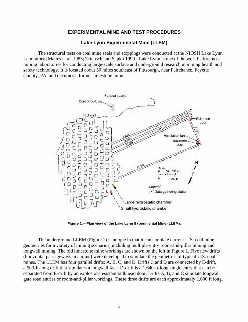
The underground LLEM (Figure 1) is unique in that it can simulate current U.S. coal mine geometries for a variety of mining scenarios, including multiple-entry room-and-pillar mining and longwall mining. The old limestone mine workings are shown on the left in Figure 1.
Figure 1.—Plan view of the Lake Lynn Experimental Mine (LLEM).
Five new drifts ical U.S. coal (horizontal passageways in a mine) were developed to simulate the geometries of typ
mines. The LLEM has four parallel drifts: A, B, C, and D. Drifts C and D are connected by E-drift, a 500-ft-long drift that simulates a longwall face. D-drift is a 1,640-ft-long single entry that can be separated from E-drift by an explosion-resistant bulkhead door. Drifts A, B, and C simulate longwall gate road entries or room-and-pillar workings. These three drifts are each approximately 1,600 ft long,
5

with seven crosscuts at the inby end. A second explosion-resistant bulkhead door is used to separate the multiple entries from E-drift at the intersection with C-drift.
Explosion tests can be conducted in the single-entry D-drift; the multiple-entry area of A-, B-, and C-drifts; or various other configurations including the longwall E-drift. The entries are about 20 ft wide by about 6.5 ft high with cross-sectional areas of 130–140 ft2. The crosscuts are 17–19 ft wide and about 7.2 ft high with a cross-sectional area of about 130 ft2.
From August 1983 (when the first explosion test was conducted) to July 2008, a total of 527 consecutively numbered explosion tests were conducted in the LLEM.
Explosion Tests in the LLEM
6
Figure 2 shows an expanded view of the test area in the multiple-entry section of the LLEM. The faces, or inby (closed) ends, of A-, B-, and C-drifts are on the right in the figure. For most of the seal and stopping tests, the explosions were conducted in C-drift and the structures were built in cross-cuts 1, 2, and 3 between B- and C-drifts, as shown in Figure 2. The evaluation of one type of seal was conducted in A-drift with the seals located in the crosscuts between A- and B-drifts. The evaluations of some of the ventilation stoppings were also conducted in A-drift as part of another explosion program with the stoppings located in X-68
8The abbreviation “X” stands for “crosscut” throughout this report, e.g., “X-1” stands for “crosscut 1.”
and X-7 between A- and B-drifts and seals located in X-1 through X-5. For clarity, the A-drift testing scenarios are not shown in Figure 2.
Figure 2.—Plan view of the LLEM showing the multiple-entry area and the seal and stopping locations. The first crosscut, designated as “#1”, is nearest the dead end of drifts A, B, or C.
Before each explosion test, a 60-t pneumatically operated, track-mounted, concrete and steel bulkhead was positioned near the intersection of C- and E-drifts to contain the explosion pressures within the multiple-entry area. The LLEM bulkhead door and some of the other infrastructure were designed to withstand explosion overpressures of up to 100 psi. Higher pressures have been recorded at areas away from these structures.

For the LLEM explosion tests, natural gas was injected into the ignition zone. This natural gas is composed of ~97%–98% methane, ~1.5% ethane, and small percentages of other higher-order hydrocarbons. Sample lines within the ignition zone were used to draw gas samples to an infrared analyzer on the surface for measurement of the methane concentration. In addition, samples were collected in evacuated test tubes and sent to verify the analyses using gas chromatography. Most of the tests used a ~9%–10% methane-air concentration within an ignition zone contained in the C-drift face area with a clear plastic diaphragm. A few of the tests used a larger gas ignition zone. A fan with an explosion-proof motor housing mixed the natural gas and air prior to ignition. Electrically activated matches located either at the face (closed end) or outby the face within the gas ignition zone, depend-ing on the explosion overpressure desired, were used to ignite the methane-air mixtures. In some of the tests, shelves of pulverized bituminous coal dust were also suspended in the drifts as a means to increase the explosion overpressures. For each of these explosion tests, the gas was ignited and the explosion pressure traveled out C-drift. For the explosion tests conducted in A-drift, the length of the gas ignition zone was varied to obtain higher total explosion overpressures at the stopping locations, i.e., the methane-air concentration was contained within a 50- or 85-ft-long gas ignition zone (as measured from the closed end of A-drift) for the different tests.
Hydrostatic Chamber Tests in the LLEM
Two hydrostatic chambers located within the high-roof section of the LLEM beyond the mouth of D-drift (Figure 1) enable researchers to impart pneumatic, hydrostatic, or explosion pressure load-ings on test seals. Figure 3 is a schematic of the chamber design showing the test seal in front of a dead-end section of tunnel excavation, the support steel surrounding the seal for simulating hitching, and the pressurization system using high-pressure water, compressed air, or some combination of the two. Sapko et al. [2005] describe the large and small hydrostatic test chambers in the LLEM in greater detail.
7
Figure 3.—Schematic of the hydrostatic chamber.

INSTRUMENTATION AND DATA COLLECTION
Pressure Waves From Test Explosions
Upon ignition with the electric matches, the methane-air mixture in the gas zone begins to burn and the flame front accelerates rapidly. In some tests, NIOSH researchers placed water-filled 55-gal barrels in the gas zone to create additional turbulence, which accelerates the flame front more rapidly. In all seal-related tests, the explosion is characterized as a deflagration as opposed to a detonation, since the maximum flame speed never exceeds about 1,100 ft/s, which is the local sound speed for the unreacted methane-air mixture.
The accelerating flame front produces pressure waves that travel at the local sound speed ahead of the flame front and are characterized by a static pressure component and a dynamic or velocity com-ponent. Both of these pressure components are time-dependent. In the free flow field, the sum of these two pressure components is the total pressure, which is also time-dependent.
Initially, the pressure waves emanating from a methane-air explosion rise from initial static pressure to peak static pressure slowly over a period of many tens of milliseconds. The time to go from initial to peak static pressure is termed the “rise time.” The leading and lower pressure part of the blast wave travels at the local sound speed. However, at higher pressure, the local sound speed increases slightly. As the pressure wave propagates, the lagging higher pressure part of the wave, which is traveling slightly faster than the leading lower pressure part of the wave, will gain on the leading lower pressure edge of the wave. Via this mechanism, the rise time of the pressure wave will decrease and the blast wave may develop into a shock wave with instantaneous rise time.
In practice, the blast waves created during some seal-related explosion tests in the LLEM had rise times on the order of 10 ms. Theoretical relationships for shock waves with instantaneous rise times apply satisfactorily to blast waves with finite rise times of this magnitude.
The dynamic pressure pV at the shock front is related to the static overpressure pS by [Glasstone and Dolan 1977; Kinney 1962; Landau and Lifshitz 1987; Zucrow and Hoffman 1985]:
5
p2 S
7 po + pS
pV = (1)2
where po = initial pressure.
For weak shock waves where pS goes to zero, pV also goes to zero; for strong shock waves where pS becomes large, pV also becomes large.
When a shock wave strikes a surface such as a seal head on, reflected overpressure pR on the seal is given by [Glasstone and Dolan 1977; Kinney 1962; Landau and Lifshitz 1987; Zucrow and Hoffman 1985]:
7 po + 4 pS
7 po + pS
pR = 2 pS (2)
where pS = static overpressure, and po = initial pressure.
8
Equation 2 applies to a nonreactive shock or blast wave in which no chemical reactions are occurring when the reflecting surface is struck. For weak shock waves where pS approaches zero, the reflected overpressure pR is two times the incoming static overpressure pS. For strong shock waves where pS becomes large, the reflected overpressure pR can be up to eight times the incoming static overpressure. For example, if the static overpressure is 117 psig, then the reflected overpressure is about 595 psig, or about five times the incoming static overpressure.
Pressure and Displacement Measurement Locations
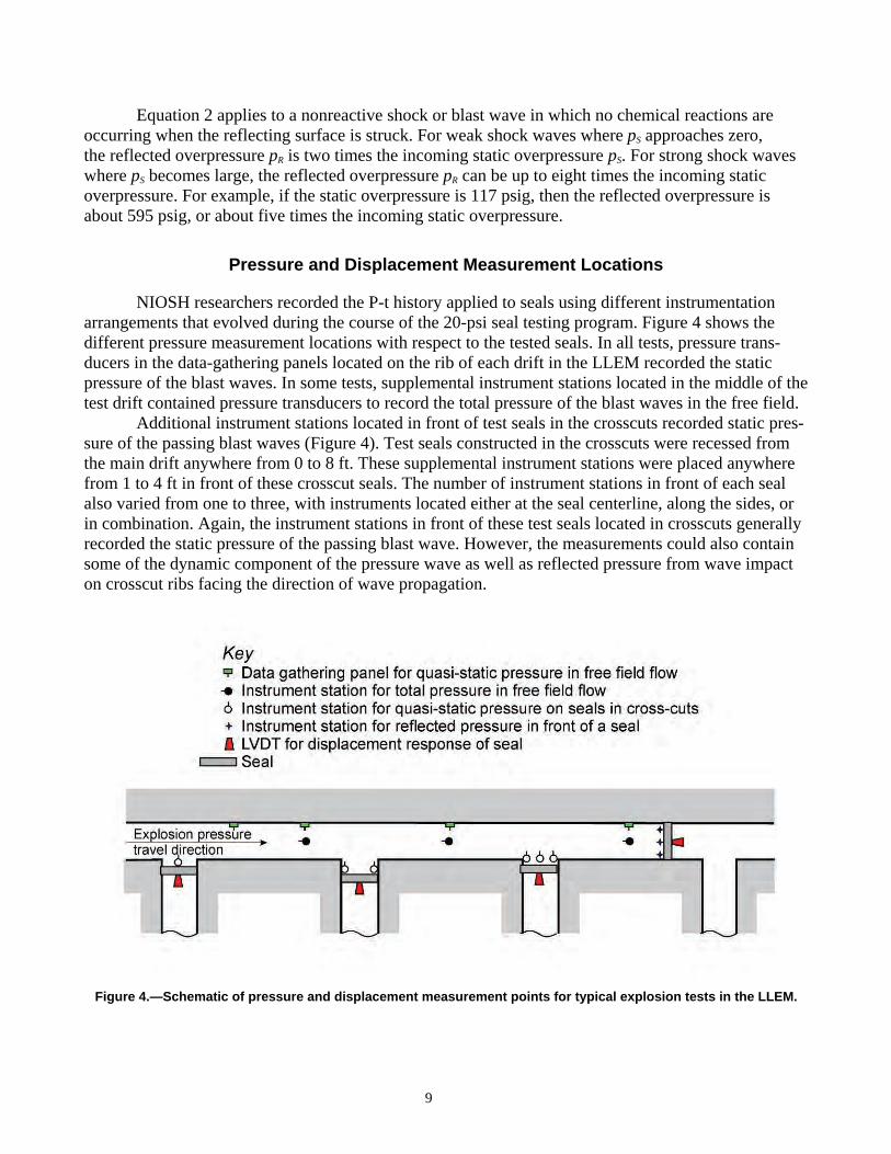
NIOSH researchers recorded the P-t history applied to seals using different instrumentation arrangements that evolved during the course of the 20-psi seal testing program. Figure 4 shows the different pressure measurement locations with respect to the tested seals. In all tests, pressure trans-ducers in the data-gathering panels located on the rib of each drift in the LLEM recorded the static pressure of the blast waves. In some tests, supplemental instrument stations located in the middle of the test drift contained pressure transducers to record the total pressure of the blast waves in the free field.
Additional instrument stations located in front of test seals in the crosscuts recorded static pres-sure of the passing blast waves (Figure 4). Test seals constructed in the crosscuts were recessed from the main drift anywhere from 0 to 8 ft. These supplemental instrument stations were placed anywhere from 1 to 4 ft in front of these crosscut seals. The number of instrument stations in front of each seal also varied from one to three, with instruments located either at the seal centerline, along the sides, or in combination. Again, the instrument stations in front of these test seals located in crosscuts generally recorded the static pressure of the passing blast wave. However, the measurements could also contain some of the dynamic component of the pressure wave as well as reflected pressure from wave impact on crosscut ribs facing the direction of wave propagation.
9
Figure 4.—Schematic of pressure and displacement measurement points for typical explosion tests in the LLEM.

Also shown in Figure 4 are instrument stations located directly in front of test seals in the main test drift. These instruments, located about 1 ft in front of the test seal, recorded the reflected wave overpressure on the test seal. The number of instrument stations varied, and the stations were located either at the seal centerline, along the sides, or in combination.
Figure 4 also shows the location of the LVDT to measure the displacement response of the structure. When used during a test, the LVDTs were located at midheight along the seal centerline.
Loading Conditions for Seal Tests
NIOSH researchers used four distinct test procedures for conducting tests on 20-psi seals. Each procedure subjected the test seal to different loading conditions as follows:
1. Explosion tests on seals in crosscuts loaded seals with the static blast wave overpressure
that is nonuniform across the tested seal face.
2. Explosion tests on seals in C-drift loaded seals with the reflected blast wave overpressure that is assumed uniform across the seal.
3. Hydrostatic chamber tests using water pressure loaded seals with a static pressure that is nearly uniform across the seal except for the minor gravity effect.
4. Hydrostatic chamber tests using methane ignition pressure loaded seals with a static over-pressure that is assumed uniform across the seal.
Most of the structural tests on seals described herein are of the first type—explosion tests on
seals in crosscuts. The test explosion began at the closed end of C-drift, and the blast wave propagated down the drift and loaded seals located in crosscuts perpendicular to the direction of the main blast wave. That test procedure induced a nonuniform, static pressure that swept across the seal face as the pressure wave propagated down the entry. The rise times of the loading are longer than the natural period of the seals, so for structural purposes, the loading is considered static. The test seal could also experience some of the dynamic pressure component and the effects of turbulence depending on how far into the crosscut the test seal is recessed. At this time, these effects are unknown and are assumed negligible.
The blast wave propagates at the local sound speed of about 1,100 ft/s, and since the seal has a width of about 20 ft, the blast wave traverses past the seal in about 18 ms. The nonuniform, sweeping static pressure across the seal at some point in time is represented approximately by an 18-ms window from the P-t curve of the blast wave. The magnitude, duration, and shape of the blast wave varied considerably from test to test. Thus, the static pressure on the seal could vary significantly from the upstream to downstream edge of the seal. For structural analysis purposes, each test will require evaluation to determine the significance of this nonuniform pressure distribution on the seal face.
Several recent structural tests on seals were of the second type—explosion tests on seals in C-drift. The test explosion began at the closed end of C-drift, and the blast wave loaded seals located across C-drift. This test procedure induced a reflected blast wave overpressure on the seal face that is assumed uniform.
10

The hydrostatic chamber tests using either water pressure (type 3 test) or methane ignition pres-sure (type 4 test) applied a static pressure across the seal face. In both test procedures, the pressure on the seal face is assumed uniform. For the water pressure test (type 3), the gravity component of the water pressure behind the test seal is assumed negligible. In the case of the methane ignition tests, the elapsed time (rise time) to develop the pressure is very long with respect to the natural period of the tested seals. Therefore, the loading is considered static for structural analysis.
Boundary Conditions for Seal Tests
The roof, rib, and floor rocks in the LLEM are limestone with a compressive strength of about 24,200 psi and a modulus of elasticity of about 9,600,000 psi, based on laboratory tests conducted by Dolinar [2008]. The rock mass in the LLEM using the 1989 version of the Rock Mass Rating (RMR) system is a good-quality rock mass, with an RMR ranging from 77 to 79 according to Esterhuizen [2008]. Therefore, the foundation conditions for seal structures constructed and tested in the LLEM represent best-case circumstances and can be described as “rigid” or “unyielding.” The foundation conditions for the seal tests in the LLEM as reported here do not represent typical conditions found in underground coal mines where the roof and floor rock and the coal ribs may have lower stiffness and strength.
Response Times, Time Constants, and Frequency Responses for Sensors Used in the LLEM
The response of a sensor to a step input depends on the range of the sensor and the time constant or frequency response of the sensor as given by the following relations:
P − t = 1−exp (3)PC T
T = 1 / F (4)
where P = magnitude of a step input, PC = full-scale range of sensor, t = response time of sensor, T = time constant of sensor,
and F = frequency response of sensor. Figure 5 shows a plot of Equation 3 in dimensionless form. For an instantaneous unit step input
(P / PC = 1), an electronic sensor will require about three dimensionless time units to reach 95% of the step input.
11

0
0.1
0.2
0.3
0.4
0.5
0.6
0.7
0.8
0.9
1
Dim
en
sio
nle
ss
re
sp
on
se -
P/P
c
0 0.5 1 1.5 2 2.5 3 3.5 4
Dimensionless time - t/T
Figure 5.—Dimensionless response function for instantaneous unit step input.
Given the measured response time of a sensor to some fraction of the full-scale range of the sensor, the time constant and frequency response of the instrument are derived from Equations 3 and 4 as follows:
P
T = t / ln 1− (5) PC
P F = − ln 1− /t (6)
PC
NIOSH researchers used numerous brands of pressure transducers during the 20-psi seal testing
program, including Patriot (AMETEK APT, Clawson, MI), Viatran (Viatran Corp., Grand Island, NY), and Transmetrics (Trans Metrics, Division of United Electric Controls, Watertown, MA). All trans-ducers used a strain-gauge array that is bonded to a flat diaphragm to measure pressure-induced deflec-tions of the diaphragm. The capacity of the pressure transducers ranged from 50 to 300 psi depending on requirements of a particular explosion test. Table 3 presents the response time (t) provided by Transmetrics, the manufacturer for the pressure transducers used in the most recent explosion tests, and the calculated time constant (T) and frequency response (F). In the calculations, it is assumed that the response time (t) is measured at 90% of the full-scale range of the sensor, i.e., P / PC = 0.9.
12

Table 3.—Response time, time constant, and frequency response for various pressure transducers used to record P-t data during LLEM tests
Full-scale range Measured response time t at Calculated time Calculated frequency of sensor (psi) 90% of full-scale (ms) constant T (ms) response F (Hz)
50 <1.6 0.70 1,439
100 <1.0 0.43 2,300
200 <0.7 0.30 3,290
300 <0.37 0.16 6,220
The data in Table 3 provide a means to judge whether pressure data measured with a particular instrument accurately record the actual phenomena. Figure 6 presents the calculated P-t response func-tion for a 100-psi step input using a 100-psi transducer with a 1.0-ms response time. As indicated by Figure 6, the 100-psi transducer subject to a 100-psi step input will develop 95% of its response in about 1.4 ms. When subject to a smaller step input, the transducer will respond according to the time function shown in Figure 6. Using a 100-psi pressure transducer, which is typical for most of the data presented herein, the transducer will record the actual phenomena to within 10% of the actual pressure as long as the rise time is more than about 1.4 ms. Therefore, when a data point defined by the rise time of the recorded response and the magnitude of the peak pressure lies below the response function shown in Figure 6, the transducer will record the phenomena reliably.
13
Re
spo
ns
e p
ress
ure
- p
si
100
90
80
70
60
50
40
30
20
10
0
0 0.2 0.4 0.6 0.8 1 1.2 1.4 1.6 1.8 2
Time - ms
Figure 6.—Calculated pressure response for instantaneous 100-psi step input. Pressure transducer has 1.0-ms response time to 90% of full-scale and 2,300-Hz frequency response.

Figure 7 presents the calculated P-t response function for a 300-psi step input using a 300-psi transducer with a 0.37-ms response time. As indicated in Figure 7, a 300-psi transducer will develop 95% of its response in about 0.4 ms. With a 300-psi pressure transducer, which was used in some of the more recent, higher-pressure explosion tests in the LLEM, the transducer will record the actual phenomena to within 10% of the actual pressure as long as the rise time is more than about 0.4 ms. The recorded P-t curve is acceptable if a data point defined by the rise time of the recorded response and the magnitude of the peak pressure lies below the response function shown in Figure 7.
0
50
100
150
200
250
300 R
es
po
ns
e p
res
su
re -
ps
i
0 0.1 0.2 0.3 0.4 0.5 0.6
Time - ms
Figure 7.—Calculated pressure response for instantaneous 300-psi step input. Pressure transducer has 0.37-ms response time to 90% of full-scale and 6,220-Hz frequency response.
NIOSH researchers closely examined all of the P-t curves presented in the appendix to this report to confirm that the data meet the response time criteria presented by the information in Table 3 and the response time functions shown in Figures 6 and 7. In general, the initial rise times are much greater than 10 ms, which is well within the response capabilities of the pressure transducers used in these experiments. A point defined by the measured rise time and the magnitude of the peak pressure always lies below the calculated response function, indicating that the data quality is acceptable and that the measured pressure data accurately reflect the actual pressure developed during the test.
NIOSH researchers used LVDTs manufactured by Honeywell Sensotec (Columbus, OH) to measure displacement response of a seal at its centerline. Measurement range for these instruments is up to 6 in. The frequency response for these instruments as stated by the manufacturer is 300 Hz, which applies when the measurement rod of the displacement transducer is coupled directly to the structure. As will be discussed later, this method of coupling was generally not done in the D-t test data
14

reported herein. Table 4 presents the frequency response provided by the manufacturer and the cal-culated time constant and response time assumed at 95% of the full-scale range of the sensor, i.e., P / PC = 0.95. Figure 8 presents the calculated D-t response to a 6-in step input using a 6-in transducer with a 10-ms response time. The measured D-t data will reliably reflect the actual D-t phenomena when the rise time up to full-scale exceeds 10 ms. For the few tests presented here where the displace-ment transducer was coupled directly to the structure, the measured rise times exceed 10 ms and the recorded D-t curves are therefore considered reliable.
15
Table 4.—Response time, time constant, and frequency response for displacement transducers
used to record D-t data during LLEM tests
Full-scale range of Response time t at 95% of Calculated time Frequency response F sensor (in) full-scale (ms) constant T (ms) (Hz)
6 <10 300 3.33
with direct coupling (calculated) (from manufacturer) 6
<75 40 with nylon filament 25.0
(measured in LLEM) (calculated) coupling
Res
po
nse
dis
pla
ce
men
t -
inch
es
6
5
4
3
2
1
0
0 1 2 3 4 5 6 7 8 9 10 11 12 13 14 15
Time - ms
Figure 8.—Calculated displacement response for instantaneous 6-in step input. Displacement transducer is coupled directly to the structure and has 10-ms response time to 95% of full-scale and 300-Hz frequency response.

NIOSH researchers also employed another method to couple the displacement transducer to the structure using a spring-loaded nylon filament to protect the LVDT from damage during an explosion test. NIOSH researchers measured the full-scale response time of the LVDT using this experimental arrangement as about 75 ms. Based on this measured response time, the calculated time constant and frequency response for the LVDT are shown in Table 4. Figure 9 presents the calculated D-t response to a 6-in step input using a 6-in transducer with a 75-ms response time. The measured D-t data will reliably reflect the actual D-t phenomena when the rise time up to full-scale exceeds 75 ms. For all of the tests presented herein where the displacement transducer was coupled to the structure with a spring-loaded nylon filament, the measured rise times exceed 75 ms and the recorded D-t curves are therefore considered reliable.
0
1
2
3
4
5
6
Re
spo
ns
e d
isp
lace
men
t -
inc
he
s
0 10 20 30 40 50 60 70 80 90 100
Time - ms
Figure 9.—Calculated displacement response for instantaneous 6-in step input. Displacement transducer is coupled via nylon filament to the structure and has 75-ms response time to 95% of full-scale and 40-Hz frequency response.
Data Acquisition System Characteristics
A PC-based data acquisition system by National Instruments Corp. (NI) (Austin, TX) recorded data from the various instruments at a sampling rate of 1,500 per second. In recent tests, a data acquisi-tion system by Kinetic Systems (KS) (Boston, MA) also recorded data from the various instruments in parallel at a sampling rate of 5,000 per second. For consistency, all data reported here come from the NI system operating at 1,500 samples per second.
16

Quality of Pressure-Time and Displacement-Time Measurements
Figure 10 presents the P-t and D-t data for the entire duration of an explosion test in the LLEM. Beyond the initial arrival and decay of the first pressure wave, the data exhibit noise spikes and other extraneous features caused by a variety of experimental realities. Two questions arise with any experi-mental data:
1. Are the data real and representative of the physical phenomena under study? 2. Are the transducers and data acquisition system adequate to record the phenomena with
sufficient detail for analysis?
0
50
100
150
200
250
Pre
ssu
re -
psi
0
1
2
3
4
5
6
Dis
pla
cem
en
t -
inch
es
Pressure_1_NI_System 1500/sec
Displacement_NI_System 1500/sec
0 0.2 0.4 0.6 0.8 1 1.2 1.4 1.6 1.8 2
Time - seconds
Figure 10.—Typical P-t and D-t data for the entire duration of an explosion test in the LLEM. Note noise spikes in data beyond 0.7 sec.
To answer these questions, Figures 11–12 present a close examination of P-t data from a recent LLEM test that generated a reflected (head-on) explosion pressure of about 200 psi; Figure 13 presents the D-t data.
Figure 11 presents P-t curves from two separate pressure transducers located close together using an expanded time scale centered near the arrival of the first pressure wave. These transducers were located on the upstream side of a seal installed across the explosion entry. The green curve is an expanded view of the same P-t curve shown in Figure 10. The NI data acquisition system recorded the data at 1,500 samples per second. By inspection, both pressure transducers record similar signals with similar peak pressures of about 200 psi and similar rise times to peak pressure of about 3–4 ms. The observed pressure rise of 200 psi over a rise time of about 3–4 ms is within the capability of the instru-ment, as shown in Figure 6. NIOSH researchers conclude that the observed peak pressures and rise times represent the pressure waves under study.
17

0
50
100
150
200
250
Pre
ss
ure
- p
si
Pressure_1_NI_System 1500/sec
Pressure_2_NI_System 1500/sec
0.51 0.515 0.52 0.525 0.53 0.535 0.54
Time - seconds
Figure 11.—Expanded time-scale view of P-t data from two separate pressure transducers. Data are recorded with the NI system at 1,500 samples per second. The green P-t curve is the same P-t curve shown in Figure 10.
250
200
Pre
ssu
re -
ps
i
0
50
100
150
Pressure_1_NI_System 1500/sec
Pressure_1_KS_System 5000/sec
0.51 0.515 0.52 0.525 0.53 0.535
Time - seconds
Figure 12.—Expanded time-scale view of P-t data from the same pressure transducer recorded with separate data acquisition systems operating at 1,500 and 5,000 samples per second.
0.54
18

Figure 12 presents an expanded view of the same P-t curve shown in Figure 10, but as recorded with two separate data acquisition systems operating at 1,500 samples per second (the NI system) and 5,000 samples per second (the KS system). By inspection, both recording systems captured similar signals, although the faster KS system provides more detail. NIOSH researchers conclude that the pressure transducers and data acquisition system are adequate to record the P-t curves from these explosion tests.
Figure 13 presents an expanded view of the D-t curve shown in Figure 10 as recorded with two separate data acquisition systems operating at 1,500 and 5,000 samples per second. For a displacement transducer coupled directly to the structure, the observed displacement of about 5.7 in over a time of 25 ms is within the capability of the instrument, as shown in Figure 8. NIOSH researchers conclude that the displacement transducer and data acquisition system are well matched to record the D-t curves from these explosion tests. However, NIOSH researchers note that while the system can measure the initial displacement response of the seal structures, it may not measure the later vibratory response of the structures because of the technique used to couple the LVDT to the structure. Thus, the displace-ment data are only reliable up to the initial peak displacement and not beyond that point in time.
19
0
1
2
3
4
5
6
Dis
pla
cem
ent
- in
ches
Displacement_NI_System 1500/sec
Displacement_KS_System 5000/sec
0.51 0.52 0.53 0.54 0.55 0.56
Time - seconds
Figure 13.—Expanded time-scale view of D-t data from the same displacement transducer recorded with separate data acquisition systems operating at 1,500 and 5,000 samples per second.

Adequacy of Pressure-Time and Displacement-Time Measurements for Structural Analysis
A final question about the P-t data concerns its adequacy for reliable structural analysis. As demonstrated in the previous sections, the pressure transducers and data acquisition system adequately capture pressure data with a rise time of at least 100 psi/ms. Higher-frequency components may exist in the P-t data that may not be captured adequately. The question arises as to whether these higher-frequency components are important in structural analysis of seals. NIOSH researchers performed a simple structural analysis aimed at discerning the possible importance of these higher-frequency P-t components.
For this structural analysis, NIOSH researchers used the Wall Analysis Code (WAC) from the U.S. Army Corps of Engineers [Slawson 1995]. WAC is a single-degree-of-freedom structural dynam-ics model that solves the equation of motion to determine the D-t history at midheight of a wall given some P-t curve applied to the wall. The analysis considered a simply supported, 2-ft-thick concrete wall. Figure 12 shows the P-t curves considered in the analysis, which were measured with the NI and KS data acquisition systems at sampling rates of 1,500 and 5,000 samples per second, respectively. Presumably, the data set collected with the KS system contains more of the higher-frequency compo-nents of the P-t curve.
Figure 14 shows the computed D-t responses from these two different P-t curves. The different responses are purposely offset in time for clarity. As seen by inspection, no significant difference exists between the two computed D-t responses. NIOSH researchers conclude that the P-t data col-lected by the NI system at 1,500 samples per second are adequate for structural analysis of seals under the conditions of the explosion tests conducted in the LLEM for evaluating 20-psi seals.
20
0.00
0.05
0.10
0.15
0.20
0.25
0.30
Dis
pla
ce
me
nt
- in
ch
es
WAC calculated displacement - 1500 sample / second data
WAC calculated displacement - 5000 sample / second data
0 5 10 15 20 25 30
Time - milliseconds
Figure 14.—Computed D-t responses for hypothetical structure using P-t curves in Figure 12 as input for structural analysis. Calculated displacements are offset in time for clarity.

Comments on Smoothing
The P-t data reported here are raw data. All data reported came from the NI system in the LLEM, which records data at 1,500 samples per second for 5 sec. In prior NIOSH publications, the P-t data reported were smoothed data derived from the raw data using a 15-point moving-average algorithm. In this simple algorithm, the midpoint (point 8) in a 15-point data set is replaced with the average value of those 15 data points. Each data point in the moving 15-point set is given equal weight in the averaging. This smoothing algorithm tends to remove the highest peaks in the pressure data. It will also slow the rate of change in the pressure data, i.e., the rise time for fast pressure changes due to blast waves and other pressure transients will decrease. Although this smoothing algorithm can remove spurious data points due to noise or other transients in the data acquisition system, structural analysis requires the use of the raw data. The actual peak pressures and rise times measured are within the capabilities of the instruments and data acquisition system. True peak pressures and pressure-rise times are important when computing the response of a structure to some applied load. Because the data reported here are raw, there will be discrepancies with the smoothed (15 points, or over a 10-ms-wide moving window) peak pressures reported in previous NIOSH reports. The pressure data herein are always higher than data reported previously.
GENERAL CONSTRUCTION DETAILS FOR CATEGORY 1 THROUGH 6 SEALS
Category 1 Seals: Concrete or Concretelike Materials With Internal Steel Reinforcement and Anchorage to Rock
Category 1 seals are made of concrete or concretelike materials such as shotcrete or gunite. The seal structure contains internal steel reinforcement and is anchored to the surrounding rock with steel reinforcement bars. Two varieties of 20-psi seals are reported here—the Insteel 3-D seal from Precision Mine Repair, Inc., made with shotcrete and steel reinforcement bar, and the Meshblock seal from R. G. Johnson Co., Inc., made with pumped cement or shotcrete and steel reinforcement bar.
Category 1A seal: Insteel 3-D seal – shotcrete with reinforcement
The Insteel 3-D seal made by Precision Mine Repair, Inc., is constructed with shotcrete, steel reinforcement bar, and reinforcement wire. Steel reinforcement bars also anchor the seal to the sur-rounding rock. NIOSH researchers tested seven different structures using these concepts and materials during development of a seal that met the previous 20-psi seal design standard (Table 1). Test results from one of these structures were reported by Sapko et al. [2005].
Figures 15 and 16 show front-, plan-, and side-view drawings of the Insteel 3-D seal for the former 20-psi seal design standard. The seal consists of a three-dimensional welded wire space frame called an Insteel 3-D panel that is encased in concrete. The structural components of the seal are the rear Insteel 3-D panel with Stayform backing, the front Insteel 3-D panel without Stayform backing, #3 steel reinforcement bars laid horizontally from rib to rib within the Insteel 3-D panels, a plane of vertical #8 reinforcement bars and #8 reinforcement bar anchors into the roof and floor in front of each Insteel 3-D panel, and horizontal #8 reinforcement bar anchors into each rib. The panels are filled com-pletely with fast-setting concrete mix applied from the front side of the seal using a shotcrete machine at a pressure of 100 psi. This mix hardens within 15 min and is nearly fully cured to design strength
21

within 24 hr. The minimum design uniaxial compressive strength requirement of this shotcrete is 2,500 psi. The finished seal is at least 11.5 in thick.
To construct the seal, the rear Insteel 3-D panels are trimmed to fit opening dimensions at the installation site and laid horizontally across the opening. Each horizontal panel contains a #3 steel reinforcement bar laid horizontally from rib to rib and spaced less than 16 in apart. The rear panel con-tains Stayform backing on the inby side, which serves as a backing for spraying the shotcrete from the outby side. Figure 17 shows a closeup view of a rear Insteel 3-D panel with the Stayform backing.
Vertical holes are drilled into the roof and floor for two rows of 36-in-long, #8 steel reinforcement bar anchors. The holes are at least 12 in deep and evenly spaced across the entry on less than 24-in centers. The front and rear rows of holes are offset laterally from each other (Figure 15).
Figure 15.—Front-, plan-, and side-view drawings of Category 1A structure: Insteel 3-D seal from Precision Mine Repair, Inc.
The #8 steel reinforcement bar anchors in the rear row are epoxy-grouted in place, and vertical #8 reinforcement bars are tied in place using preformed clamps between corresponding roof and floor anchors. The rear Insteel 3-D panel with Stayform backing is then tied with wire to the rear row of vertical #8 steel reinforcement bar. Three holes are also drilled on 24-in centers into each rib at least 12 in deep for additional anchorage, and #8 steel reinforcement bar anchors are epoxy-grouted into place and tied to the #3 steel reinforcement bars within the Insteel 3-D panels. Figure 18 shows the reinforcement construction at this stage.
22

Figure 16.—Detailed plan-view drawing of Category 1A structure: Insteel 3-D seal from Precision Mine Repair, Inc.
Figure 17.—Closeup of a rear Insteel panel with Stayform backing and the horizontal #3 steel reinforcement bars.
23

Figure 18.—Insteel 3-D seal under construction showing the rear Insteel panel with Stayform backing, one plane of vertical #8 steel reinforcement bars and anchors, the horizontal #8 steel reinforcement bar anchors, and the horizontal #3 steel reinforcement bars.
The front Insteel 3-D panels without Stayform backing are then trimmed to fit the opening dimensions and laid horizontally in front of the rear plane of vertical #8 steel reinforcement bar. The front row of #8 steel reinforcement bar anchors is epoxy-grouted into place, and vertical #8 steel reinforcement bars are tied in place using preformed clamps between corresponding roof and floor anchors. The front Insteel 3-D panel is tied with wire to the front row of vertical #8 steel reinforcement bars. Figure 19 shows the reinforcement construction at this stage. The wire mesh and steel reinforce-ment bar network is now ready for spraying with shotcrete with a minimum design uniaxial compres-sive strength of 2,500 psi to a depth of at least 11.5 in.
24
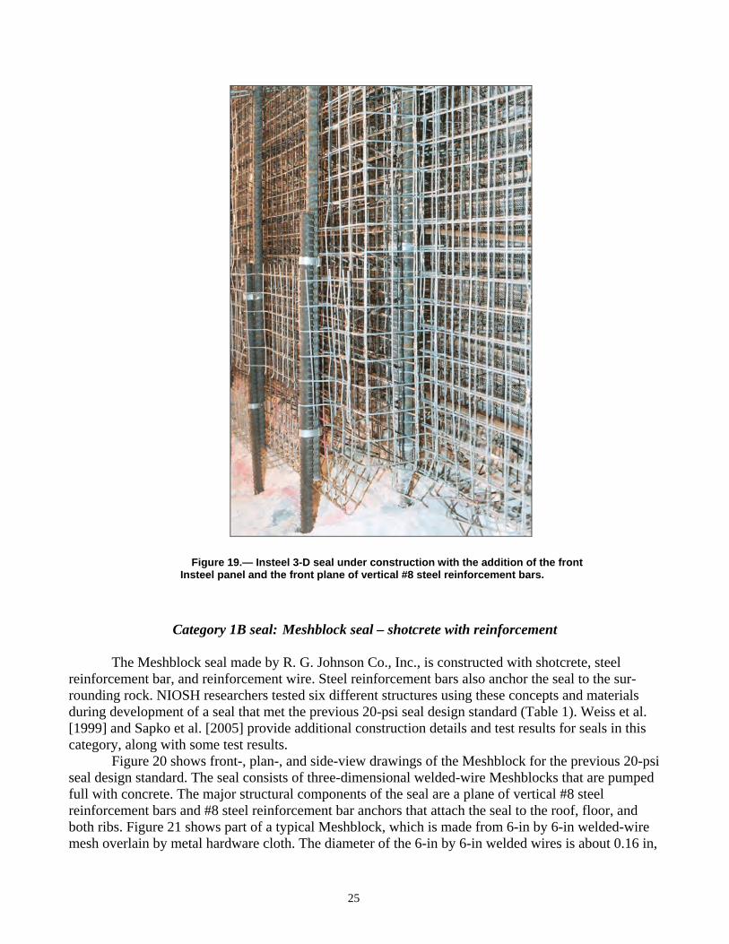
Figure 19.— Insteel 3-D seal under construction with the addition of the front
Insteel panel and the front plane of vertical #8 steel reinforcement bars.
Category 1B seal: Meshblock seal – shotcrete with reinforcement
The Meshblock seal made by R. G. Johnson Co., Inc., is constructed with shotcrete, steel reinforcement bar, and reinforcement wire. Steel reinforcement bars also anchor the seal to the sur-rounding rock. NIOSH researchers tested six different structures using these concepts and materials during development of a seal that met the previous 20-psi seal design standard (Table 1). Weiss et al. [1999] and Sapko et al. [2005] provide additional construction details and test results for seals in this category, along with some test results.
Figure 20 shows front-, plan-, and side-view drawings of the Meshblock for the previous 20-psi seal design standard. The seal consists of three-dimensional welded-wire Meshblocks that are pumped full with concrete. The major structural components of the seal are a plane of vertical #8 steel reinforcement bars and #8 steel reinforcement bar anchors that attach the seal to the roof, floor, and both ribs. Figure 21 shows part of a typical Meshblock, which is made from 6-in by 6-in welded-wire mesh overlain by metal hardware cloth. The diameter of the 6-in by 6-in welded wires is about 0.16 in,
25

and the opening size in the hardware cloth is about 0.12 in. Overall dimensions for a Meshblock are 42 in wide by 18.25 in high by 12 in deep. The space between the Meshblocks is filled with shotcrete (Figure 22). The shotcrete brand used is Quikrete MB-500, which is a mixture of cement and minus 0.20-in aggregate and has a minimum design uniaxial compressive strength of 5,800 psi.
To construct the seal, vertical holes are drilled 24 in deep into the roof and floor on 24-in centers. Additional horizontal holes are drilled 24 in deep into ribs on 40-in centers. Steel reinforcement bars, 48 in long and 1 inch in diameter, are resin-anchored into each hole (Figure 20). Vertical #8 steel reinforcement bars that overlap the anchor bars by 24 in are tied using preformed clamps to the corresponding roof and floor anchors. This reinforcement plane is centered in the Meshblock formwork.
The Meshblock formwork is then pumped full with shotcrete. The metal hardware cloth facing on the Meshblocks allows the nozzleman to examine the shotcrete flowing into the formwork (Figure 22). Normally, two layers of Meshblock units are filled at a time. Care is required to limit pouring delays to less than 30 min to prevent cold joints in the finished structure. The top 6–12 in of the seal requires cutting and fitting the Meshblock units to create a back wall, which is filled in with the shotcrete using the spray nozzle. Finally, the perimeter is sprayed to stabilize and seal the surround-ing strata.
26
Figure 20.—Front-, plan-, and side-view drawings of Category 1B structure: Meshblock seal from R. G. Johnson Co., Inc.

Figure 21.—Closeup of Meshblock seal under construction showing the Meshblocks and the vertical #8 steel reinforcement bars and anchors.
Figure 22.—Meshblock seal under construction showing the lower Meshblocks, the vertical #8 steel reinforcement bars and anchors, and placement of shotcrete.
Category 2 Seals: Pumpable Cementitious Materials With No Steel Reinforcement and No Hitching
Category 2 seals are also called pumpable seals and are made from cementitious materials of various compositions. Different formulations will produce different compressive strengths for the pumpable cementitious material. Lower-strength materials will require a thicker seal. These seals do not contain any internal steel reinforcement and are not hitched to the surrounding rock. Friction between the seal material and the surrounding rock holds the seal in place. Three varieties of 20-psi seals are reported here with different compressive strength materials and different seal thicknesses.
27

Category 2A seal: Pumpable cementitious material with uniaxial compressive strength of 200 psi constructed 48 in thick
Category 2A seals include Tekseal manufactured by Minova, Inc., and Celuseal manufactured by R. G. Johnson Co., Inc. These seals are made from a pumpable cementitious material with a mini-mum design uniaxial compressive strength of at least 200 psi and a thickness of at least 48 in. NIOSH researchers tested four different structures in this category during development of a seal that met the previous 20-psi seal design standard (Table 1). Greninger et al. [1991], Weiss et al. [1993, 1996], Weiss and Harteis [2008], and Sapko et al. [2005] provide additional details on constructing the pumpable, cementitious material seals in this category along with some test results.
Figure 23 shows front-, plan-, and side-view drawings of the typical formwork for a pumpable cementitious material seal. The two form walls must have sufficient strength to resist the pressure from the uncured cementitious seal material. The formwork shown in Figures 23 and 24 consists of 4-in by 4-in vertical wood posts installed on 3-ft centers across the entry, 1-in by 6-in wood boards nailed hori-zontally across the timbers on less than 2-ft centers, and MSHA-approved brattice material nailed to the inside of the frame. The brattice material must overlap approximately 4 in and is secured onto each rib, the roof, and the floor. The forms do not add any significant structural strength to the seal. Finally, the volume between the two forms is pumped full of cementitious material (Figure 25).
28
Figure 23.—Front-, plan-, and side-view drawings of Category 2 structure made from pumpable cementitious materials with no steel reinforcement and no hitching.

Figure 24.—Formwork for a typical pumpable seal showing the vertical posts, the horizontal boards, and the brattice liner (partially removed).
Figure 25.—Inside the formwork of a typical pumpable seal show- ing the brattice liner and the cementitious filling material.
Tekseal and Celuseal are both lightweight, noncombustible cement-based products. Cementi-tious powder, water, and air are metered into a continuous mixer and then pumped between the forms. The amount of cementitious material used per cubic yard of seal determines the density and strength of the seal material. These seals should normally be installed using a continuous pour during construction so that a solid plug with no cold joints is obtained.
29

Category 2B seal: Pumpable cementitious material with uniaxial compressive strength of 433 psi constructed 36 in thick
Category 2B seals include the Ribfill seal made by HeiTech Corp. Again, these seals are made from a pumpable cementitious material with a minimum design uniaxial compressive strength of at least 433 psi and a thickness of at least 36 in. NIOSH researchers tested one structure in this category during development of a seal that met the previous 20-psi seal design standard (Table 1). Weiss et al. [2002] provide additional details on constructing the pumpable, cementitious material seals in this category along with test results.
Construction of the seal uses a formwork similar to that shown in Figures 23 and 24, except that the distance between form walls is at least 36 in and the minimum design uniaxial compressive strength of the cementitious material must exceed 433 psi.
Category 2C seal: Pumpable cementitious material with uniaxial compressive strength of 480–600 psi constructed 24–30 in thick
Category 2C seals include the Rockfast seals also made by HeiTech Corp. NIOSH researchers tested four different structures in this category during development of a seal that met the previous 20-psi seal design standard (Table 1). Weiss et al. [2002] provide additional details on constructing the seals in this category along with test results.
The Rockfast M-FGL material used for these seals is a modified, portland cement-based, fiber-reinforced, pumpable grout that exhibits rapid gelation and high early strength. The 24-in-thick version of this seal requires material with a minimum design uniaxial compressive strength of 677 psi, while the 30-in-thick version requires material with a minimum design uniaxial compressive strength of 480 psi. Construction of the seal uses a formwork similar to that shown in Figures 23 and 24, except that the distance between form walls is 24–30 in.
Category 3 Seals: Articulated Structures – Solid and Hollow-Core Concrete Blocks With or Without Hitching
Category 3 seals are articulated structures made from discrete concrete blocks bonded together with a mortar. These seals may or may not be hitched into the surrounding rock, and they do not con-tain any internal steel reinforcement. Two varieties of seal structures are reported here: the standard solid-concrete-block seal, which is hitched into the surrounding rock, and a variant of the standard seal that uses pressurized grout bags in lieu of hitching to attach the seal structure to the surrounding rock through friction. Also included in this category are ventilation stoppings made from solid and hollow-core concrete blocks. These stoppings are constructed by dry stacking the blocks without mortar and without hitching and only wedging along the ribs and roof. Test results from these structures are included here since these structures can form an integral part of other seal structures in other seal categories.
30

Category 3A seal: Standard solid-concrete-block seal with hitching
The seal design in Category 3A is the original 20-psi standard seal, also known as the Mitchell-Barrett mine seal. The seal is constructed with wet-laid, solid concrete blocks, a central pilaster for added strength, and hitching into the ribs and floor. NIOSH researchers tested seven different struc-tures in this category (Table 1). Greninger et al. [1989, 1991], Weiss et al. [1993, 1996] and Sapko et al. [2005] provide additional details on constructing the standard solid-concrete-block seals in this category along with test results.
Figure 26 shows front-, plan- and side-view drawings of the typical standard solid-concrete-block seal as constructed in the LLEM. The seal is constructed with solid concrete blocks measuring either 8-in by 8-in by 16-in or 6-in by 8-in by 16-in (laid flat) and placed with ASTM Type S mortar. The mortar is applied on all vertical and horizontal block joints to a nominal thickness of 3/8 in. The blocks in the first course are placed with their long axis parallel to the rib. Blocks in the second course are oriented perpendicular to the first course, and the front and back rows in this course may or may not be staggered.
31
Figure 26.—Front-, plan-, and side-view drawings of Category 3A structure: standard solid-concrete-block seal with simulated hitching.

The seal is constructed 16 in thick with a center pilaster measuring 16 in wide by 32 in thick for added strength (Figures 26–27). Blocks are cut and laid on the last course so that a gap approximately 1–2 in high exists between the top course of block and the mine roof (Figure 28). This gap is filled completely with mortar across the width and depth of the seal. No wedges are used in the seal con-struction. Finally, the faces on both sides of the seal are coated with mortar or other surface sealant approved by MSHA.
Figure 27.—Solid-concrete-block seal under construction showing the center pilaster and the fully mortared joints on all sides.
Figure 28.—In background, top of a solid-concrete-block seal showing small cut blocks and mortar filling at the seal top.
In practice, the standard solid-concrete-block seal is hitched into the floor and rib by excavating at least 6 in into solid competent material. To simulate hitching during tests in the LLEM, NIOSH researchers use 6-in by 6-in by 0.5-in-thick steel angle (Figure 29), anchored on 18-in centers using 1-in-diam by 9-in-long anchor bolts. The nominal uniaxial compressive strength of the block material is 1,900 psi, although recent full-scale block testing by Barczak and Batchler [2008] indicates a solid-concrete-block uniaxial compressive strength of 1,330–1,780 psi. Design uniaxial compressive strength of the mortar exceeds 1,900 psi.
32

Figure 29.—Completed solid-concrete-block seal without a center pilaster
showing the angle iron hitch on the ribs and floor only.
Category 3B seal: Solid-concrete-block seal with Packsetter Bags and without hitching
The 20-psi seal design in Category 3B is similar to the standard solid-concrete-block design described above, except that Packsetter Bags distributed by Strata Mine Services are used in place of conventional hitching. NIOSH researchers tested three different structures in this category (Table 1). Weiss et al. [2002] provide additional details on constructing the concrete block with grout bag seals in this category along with test results.
Figure 30 shows front-, plan-, and side-view drawings of the typical standard solid-concrete-block seal with Packsetter Bags as constructed in the LLEM. The seal is constructed with tongue-and-groove, solid concrete blocks measuring either 8 in by 8 in by 16 in or 6 in by 8 in by 16 in (laid flat) and placed with mortar on all surfaces to a nominal thickness of 3/8 in. The mortar used must meet ASTM C270-91a as Type N, S, or M mortar. BlocBond from Quikrete is also considered an acceptable mortar. The seal has a central pilaster measuring 16 in wide by 32 in deep.
Construction of this seal begins with placement of the first course of tongue-and-groove block laid parallel to the rib in wet mortar to within 2 in of each rib. A Packsetter Bag is laid flat and posi-tioned at least 6 in under the outside corners of the first course of blocks. Placement of wet-laid con-crete blocks continues until the blocks come within 2–5 in of the roof and ribs. Packsetter Bags placed along the ribs and across the roof overlap adjacent bags by a minimum of 6 in and overlap the front and back face of the seal by at least 3 in. The top-right and top-left corner Packsetter Bags are placed with half the bag down the rib side and half the bag across the roof side of the seal. Because of possible rib and roof undulations, if the distance between seal and strata is up to 8 in due to a localized cavity, a spacer Packsetter Bag can be used.
33

Figure 30.—Front-, plan-, and side-view drawings of Category 3B structure: solid-concrete-block seal with Packsetter Bags.
After all seal material and Packsetter Bags are in position, grout is pumped into the bags in a sequence beginning with the top-right and top-left bags, followed by the bags along the roof line, followed by the bottom-right and bottom-left bags, and concluding with the bags along the rib lines. Each bag is pressurized with grout to 36–44 psi using a compressor-driven or hand pump, and the bags will load the seal horizontally and vertically upon installation. The Packsetter Bag grout is a specially formulated portland cement-based mixture blended and packaged for Strata Mine Services by Quikrete. It develops a uniaxial compressive strength of 580 psi after 28 days.
After the grout bags are filled, polyurethane foam is used to fill any small gaps at the roof and ribs or between Packsetter Bags. Finally, the outby side of the seal is coated with an MSHA-approved general-purpose sealant to minimize leakage through the seal. Figure 31 shows a nearly complete tongue-and-groove, solid-concrete-block seal with Packsetter Bags.
34

Figure 31.—Tongue-and-groove, solid-concrete-block seal with center pilaster using pressurized Packsetter grout bags in lieu of hitching around the seal perimeter. The worker is coating the seal with an approved sealant.
Category 3C seal: Ventilation stoppings – solid and hollow-core concrete blocks
Ventilation stoppings are sometimes constructed from dry-stacked solid or hollow-core con-crete blocks. Numerous such stoppings have been explosion tested in the LLEM. Although this kind of ventilation stopping is not a seal, it is a type of articulated structure. Solid or hollow-core concrete blocks are often part of seal construction, serving either as an integral part of the seal structure or as a form wall for some other seal construction material. The applied loads and measured responses from tests on these ventilation stoppings may provide useful structural information for analyzing and design-ing other mine seals, so the test results are included here. NIOSH researchers tested eight different structures in this category (Table 1)—four constructed with solid concrete blocks and four with hollow-core concrete blocks. Weiss et al. [2008] provide additional details on constructing the venti-lation stoppings in this category along with test results.
Figure 32 shows front-, plan-, and side-view drawings of the typical ventilation stopping con-structed with either solid or hollow-core concrete blocks. The hollow-core concrete blocks measure 6 in by 8 in by 16 in and have a nominal uniaxial compressive strength for the block material of 1,900 psi. Recent full-scale wall testing by Barczak and Batchler [2008] indicates a hollow-core con-crete block uniaxial compressive strength of less than 1,000 psi. For three of the solid-concrete-block structures, the blocks also measure 6 in by 8 in by 16 in; for the other structure, the blocks measure 8 in by 8 in by 16 in. The nominal uniaxial compressive strength of the solid-concrete-block material was 1,900 psi. However, recent full-scale wall testing by Barczak and Batchler [2008] indicated a solid-concrete-block compressive strength of 1,330–1,780 psi.
Wood wedges are used to tighten each course of blocks along the ribs and on the top course of blocks against the roof (Figures 32–33). Finally, a layer of Quikrete BlocBond sealant is applied to both faces of the stopping (Figure 34).
35

36
Figure 32.—Front-, plan-, and side-view drawings of Category 3C structure: solid or hollow-core concrete block ventilation stoppings.

Figure 33.—Dry-stacked concrete block stopping showing wedges used to fit the stopping to ribs and small cut blocks and a wood plank at the top.
Figure 34.—Dry-stacked concrete block stopping showing
application of an approved sealant to the surface.
37

Category 4 Seals: Polymer and Aggregate Materials Without Hitching
The MICON 550 permanent ventilation seal constructed by MICON is the sole representative of the Category 4 seals. This seal is constructed with two dry-stacked hollow-core concrete block stop-ping walls separated by about 18 in and filled with a mixture of two-component polyurethane foam and crushed limestone aggregate. No hitching of this structure is used except through friction with the sur-rounding rock. We present data from only one structure in this category (Table 1). Weiss et al. [1996] provide additional details on constructing polymer and aggregate seals in this category along with test results.
Figure 35 shows front-, plan-, and side-view drawings of the MICON 550 seal. The back dry-stacked, hollow-core concrete block wall is constructed first. Upon placement of the last block of each row, a wedge is driven between the block and rib to firmly tighten the blocks in that row. All notches and holes are filled with the largest block fragments possible and wedged in place. The back wall is coated on the outside surface with an MSHA-approved sealant for dry-stacked concrete block walls. Note that MSHA-approved sealants for dry-stacked walls are listed separately from general-purpose sealants.
38
Figure 35.—Front-, plan-, and side-view drawings of Category 4 structure: polymer and aggregate seal.

The front block wall is constructed to a height of 2–3 ft depending on seal height, and the central portion of the front wall is constructed all the way to the roof in a pyramid shape (Figure 36). After one or two top blocks are in place, wedges are driven between the block and roof to hold the wall in place.
Figure 36.—Polymer and aggregate seal from MICON showing the rear dry-stacked, hollow-core concrete block wall, the partially completed front wall, a polymer coating on the inside surface of the form walls, and an approved sealant on the outside surface of the form wall.
With the back wall completed and part of the front wall in place, construction of the inner core can begin. Construction of the inner core continues simultaneously with additional construction of the front wall. The outside of the front wall is also coated with an MSHA-approved sealant for dry-stacked concrete block walls. Note that the concrete blocks must be dry for adequate bonding of the poly-urethane foam in the inner core.
The initial step in constructing the inner core is to coat the floor, the inside of the block walls, the roof, and the ribs within the core area with a high-density, 70 lb/ft3 polymer to prevent moisture from affecting the density of the polyurethane core. This coating on the inner wall is indicated in Figures 35–36. Installation then proceeds as follows:
1. A 4-in-thick layer of dry crushed limestone aggregate, ranging in size from 0.25 to 1 in, is placed as the initial lift.
2. The initial layer of limestone is completely coated with polyurethane foam (Figure 37) having a density of at least 10 lb/ft3. As the polymer reacts, it expands and rises through with the crushed limestone, then hardens within 5 min.
3. Steps 1 and 2 are repeated to the roof to complete the seal.
The polyurethane foam and aggregate core must achieve a density of at least 35 lb/ft3 after curing for 24 hr.
The dry-stacked and coated concrete block walls remain in place after seal construction since these walls are an integral part of the structure. If the wall deteriorates, it will require repair. Any exposed polyurethane is coated with an MSHA-approved fire-retardant sealant, both immediately after seal construction and at any later time in the life of the seal.
39

Figure 37.—Polymer and aggregate seal from MICON showing the rear and front form wall, the polymer coating on the inner surfaces of the form walls, and the polyurethane foam and aggregate mixture filling the inner core of the seal.
Category 5 Seals: Wood-Crib-Block Seals With or Without Hitching
Category 5 seals made mainly from wood crib blocks are intended for use where high conver-gence is expected. These wood seals crush substantially, but may still retain their ability to resist explosion pressure and not leak air in or out of the sealed area. Two varieties of wood seals are described here: the wood-crib-block seal, which is nailed together and hitched into the surrounding rock; and a variant of this wood seal, which is glued together with construction adhesive and uses pressurized grout bags in lieu of hitching to attach the seal structure firmly to the surrounding rock.
Category 5A seal: Wood-crib-block seal with hitching
Category 5A wood crib seals are used in mines with high convergence where the forces result-ing from convergence might crack the standard solid-concrete-block seal, rendering it ineffective. We have no data to report on this structure, but describe it here for completeness. Weiss et al. [1993] provide details on constructing wood-crib-block seals in this category.
Figure 38 shows front-, plan-, and side-view drawings of the typical construction of a modified wood-crib-block seal. Crib blocks are at least 36 in long and measure either 5 in by 5 in or 6 in by 6 in. They are installed horizontally with their length parallel to the ribs. Each crib block is toenailed to the crib block in the lower course using three 4-in-long common nails spaced on 9-in centers, or a 0.5-in-thick layer of rock dust is placed between courses of crib blocks (Figure 39). Voids around the perim-eter are wedged tight. In practice, the seal is hitched into the ribs and floor by excavating into solid material at least 6 in. For testing in the LLEM, NIOSH researchers simulate hitching with 6-in by 6-in by 0.5-in-thick steel angle on the floor and ribs (Figure 40). The steel angle is anchored on 18-in centers using 1-in-diam by 9-in-long anchor bolts. Additionally, 5/8-in-thick exterior plywood sheeting is nailed on both sides of the seal using 4-in common nails on 6-in centers. An approved sealant is applied around the perimeter and at the joints in the plywood sheeting on both faces (Figure 40).
40

Figure 38.—Front-, plan-, and side-view drawings of Category 5A structure: wood-crib-block seal with plywood facing and simulated hitching.
Figure 39.—Closeup of a hitched wood-crib-block seal showing the layer
of rock dust placed between each layer of wood crib blocks.
41

Figure 40.—Construction of a hitched wood-crib-block seal without plywood facing showing the wood crib blocks separated by a rock dust layer, the angle iron hitching around the ribs and floor only, and the final coating with an approved sealant.
Category 5B seal: Wood-crib-block seal with glue and Packsetter Bags
Category 5B wood crib seals are also used in mines that have high convergence where other seals might fail because of cracking. The seals are constructed similar to the ordinary Category 5A wood-crib-block seals, except that Packsetter Bags are used in place of hitching. We present data from only one structure in this category (Table 1). Sapko et al. [2003] provide details on constructing the wood crib block with grout bag seals in this category.
Figure 41 shows front-, plan-, and side-view drawings of the typical construction of a wood-crib-block seal with Packsetter Bags. The seal consists of 30-in-long wood crib blocks that measure from about 5-in by 5-in to 6-in by 6-in, appropriate glue and applicator, and Packsetter Bags with the necessary grout. Construction of the seal begins by applying a layer of adhesive to the mine floor. The first course of wood crib blocks is then laid across the floor or footer in the adhesive. The length of the crib block is oriented parallel with the ribs. No hitching to the roof, ribs, or floor is necessary. A Packsetter Bag is positioned under the corners of the first course of crib blocks by at least 6 in. The crib blocks are glued together with FOMO Handi-Stick adhesive and a special applicator (Figure 42). Each crib block requires three rows of adhesive about 0.5 in wide applied to the top and each side of each crib block along its entire length.
In subsequent rows of crib blocks, the vertical joints are staggered (Figures 41 and 43). The wood crib blocks are placed to within 2–5 in of the roof and ribs to allow space for the Packsetter Bags. The bags along the ribs and across the roof overlap adjacent bags by a minimum of 6 in and the front and back face of the seal by at least 3 in. The top-right and top-left corner Packsetter Bags are placed with half the bag down the rib side and half the bag across the roof side of the seal. A spacer Packsetter Bag is used to fill gaps up to 8 in caused by rib and roof undulations. The Packsetter Bag grout is a specially formulated portland cement-based mixture blended and packaged for Strata Prod-ucts, Inc., by Quikrete and has a compressive strength of 580 psi after 28 days.
After wood crib blocks and Packsetter Bags are in position, grout is pumped into the bags to a pressure of 50 psi in a sequence beginning with the top-right and top-left bags, followed by the bags
42

along the roof line, then the bottom-right and bottom-left bags, and concluding with the bags along the rib lines. This pressurization provides artificial horizontal and vertical loading on the seal upon installation. Polyurethane foam is used to fill any small gaps at the roof, ribs, or between Packsetter Bags. The active mine side of the seal is covered with brattice secured with several pieces of wood nailed to the seal. The brattice overlaps the seal perimeter at the roof, rib, and floor by at least 1 ft. Finally, the active mine side of the seal is coated with an MSHA-approved general-purpose sealant.
Figure 41.—Front-, plan-, and side-view drawings of Category 5B structure: wood-crib-block seal with Packsetter Bags.
43
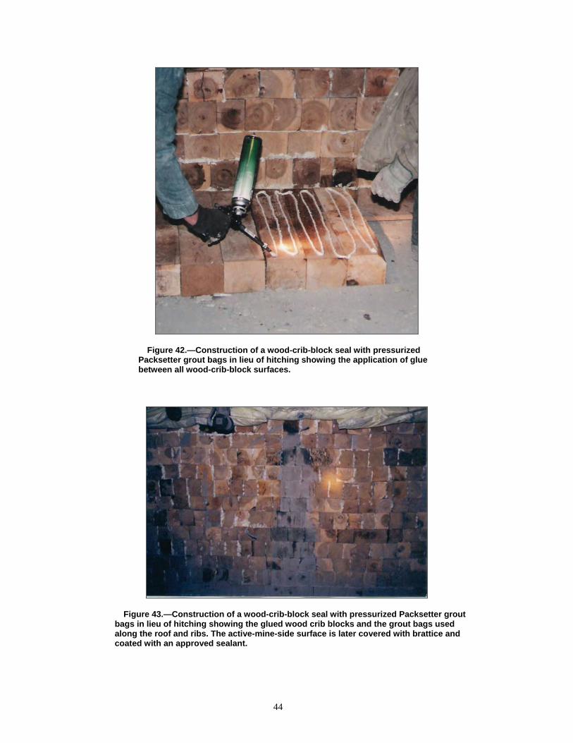
Figure 42.—Construction of a wood-crib-block seal with pressurized Packsetter grout bags in lieu of hitching showing the application of glue between all wood-crib-block surfaces.
Figure 43.—Construction of a wood-crib-block seal with pressurized Packsetter grout bags in lieu of hitching showing the glued wood crib blocks and the grout bags used along the roof and ribs. The active-mine-side surface is later covered with brattice and coated with an approved sealant.
44

Category 6 Seals: Articulated Structures – Lightweight Blocks With or Without Hitching
Category 6 seals are articulated structures made from lightweight Omega blocks manufactured by Burrell Mining Products International, Inc. The Omega blocks are noncombustible, glass-fiber reinforced blocks measuring 8 in by 16 in by 24 in, weighing about 46 lb and having a compressive strength of 70–110 psi. The blocks can be cut with a handsaw to fit into spaces between seal and rib or roof where full blocks will not fit. Two varieties of seal structures composed of lightweight blocks are reported here: 24-in-thick seals that require hitching and 40-in-thick seals that do not require hitching.
In Omega block seal construction, all horizontal and vertical joints are coated with 0.25-in-thick BlocBond mortar manufactured by Quikrete Company. BlocBond, a mortar mix containing port-land cement, fiberglass fiber, and additives, is the only mortar permitted in the construction of Omega Block seals. A layer of BlocBond is applied to the floor for setting the first course of blocks. BlocBond is also placed between the blocks and the coal ribs and between the top blocks and the mine roof. Loose material is brushed off of each block, then blocks are wetted before applying the BlocBond. Finally, all outside faces are coated completely with a 0.25-in-thick layer of the BlocBond mortar.
Category 6A seal: Lightweight blocks 24 in thick with hitching
The Category 6A 20-psi seal designs are made with Omega blocks constructed 24 in thick with a 48-in by 48-in center pilaster for added strength. NIOSH researchers tested two different structures in this category (Table 1). Sapko et al. [2005] and Cashdollar et al. [2007] provide additional details on constructing the lightweight block seals in this category along with test results.
Figure 44 shows front-, plan-, and side-view drawings, and Figure 45 shows the construction of this Omega block seal with hitching. All block surfaces are coated with a 0.25-in-thick layer of BlocBond mortar. Two wood planks are placed across the top of the blocks and wedged against the roof (Figure 46). Wood planks are also placed on top of each pilaster and wedged against the roof. Spaces between the wood planks and wedges are filled with BlocBond mortar. To simulate hitching during the LLEM tests, NIOSH researchers use a 6-in by 6-in by 0.5-in-thick steel angle on the floor and ribs that is anchored on 18-in centers using 1-in-diam by 9-in-long Hilti Kwik Bolts. Figure 47 shows a completed Omega block seal with the angle iron to simulate hitching.
45
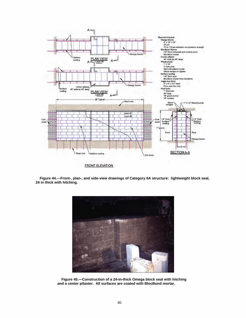
Figure 44.—Front-, plan-, and side-view drawings of Category 6A structure: lightweight block seal, 24 in thick with hitching.
Figure 45.—Construction of a 24-in-thick Omega block seal with hitching and a center pilaster. All surfaces are coated with BlocBond mortar.
46

Figure 46.—Construction of an Omega block seal showing the wood board and wedges used to secure the seal at the roof.
Figure 47.—Completed 24-in-thick Omega block seal showing the angle iron hitch along the ribs and floor and the outer surface coated with an approved sealant.
Category 6B seal: Lightweight blocks 40 in thick without hitching
The Category 6B 20-psi seal designs are made with Omega blocks constructed 40 in thick and without a center pilaster for added strength or simulated hitching with steel angle at the floor and ribs. NIOSH researchers tested eight different structures in this category (Table 1). Weiss et al. [1993, 1996], Weiss and Harteis [2008], Sapko et al. [2003], and Cashdollar et al. [2007] provide additional details on constructing the lightweight block seals in this category along with test results.
Figure 48 shows front-, plan-, and side-view drawings of the typical Omega block seal without hitching. Figure 49 shows the same seal design under construction. Joints in alternate courses of blocks are staggered. Three rows of 1-in by 12-in wood planks are placed from rib to rib across the top of the
47

seal. One row of planks is placed along the center of the seal; the other two rows are placed with their edges flush with the inby and outby faces of the seal, respectively. Joints in the planking are staggered, and the planking is set in a thin layer of BlocBond. Wedges are driven on 6- to 12-in centers between the planks and roof to compress the planks uniformly against the Omega blocks. BlocBond is used to fill all the gaps between the mine roof and the top block course, including the areas between the rows of wood planks and the gaps between the wooden wedges. Finally, all exposed wood and the outside faces are coated with BlocBond.
48
Figure 48.—Front-, plan-, and side-view drawings of Category 6B structure: lightweight block seal, 40 in thick without hitching.

Figure 49.—Construction of a 40-in-thick Omega block seal without hitching and no center pilaster. All surfaces are coated with BlocBond mortar.
STRUCTURAL TESTING DATA FOR 20-psi COAL MINE SEALS
Table 1 provides an overview of the NIOSH testing program on 44 different seal structures and 8 stoppings. As the table indicates, the program subjected many structures to multiple or repeated pres-sure loads and tested many structures to failure. For some of the structures tested, the only data avail-able are the applied P-t curve and an indicator of whether the structure survived or failed under that applied load. However, for most of the tests, the applied P-t curve and the measured D-t response are reported here.
Tables 5 through 10 provide expanded information for each of the six seal categories, including the structure number for each individual seal structure constructed and tested, the type and number of tests on that structure, the loading condition on that structure (static or reflected, nonuniform or uni-form), a reference figure that most closely describes that structure, and a brief description of the struc-ture. Again, the test program includes 52 separate structures (44 seals and 8 stoppings).
Table A-1 in the appendix provides detailed information for each seal structure and each test on that structure. Column 1 in the table gives the seal category and structure, a brief description, the name of the manufacturer or constructor, NIOSH publications related to that particular seal structure, and the name of the Excel file containing the raw data for the P-t and D-t curves associated with that seal. The Excel data files will be posted and available on the NIOSH Mining Web site (http://www.cdc.gov/niosh/mining).
Column 2 in Table A-1 gives the location where the structure was constructed and tested; the exact height, width, and thickness for that particular seal structure; the type of test from previous tables; and the loading condition (also from previous tables). For most of the LLEM explosion tests, the location is the crosscut number between either the A- and B-drifts or B- and C-drifts. Other struc-tures were tested in the small or large hydrostatic test chambers in the LLEM.
For each unique structure tested, column 3 in Table A-1 gives a detailed description of how that seal was constructed. This information comes directly from the LLEM test descriptions. Although the construction details will generally follow the descriptions given in the previous section, each structure
49

tested is unique. For example, the shotcrete thickness in the Category 1A seals will vary from structure to structure, and the steel reinforcement may change somewhat from structure to structure. Those details, if available, are provided in the description in column 3.
Column 4 in Table A-1 gives the LLEM test numbers that subjected the particular structure to an explosion loading. Each explosion test in the LLEM since the inception of the facility in 1983 has been assigned a sequential number. As indicated in Table 1, most of the structures reported herein were subjected to multiple explosion loadings prior to either failure of that structure or cessation of further testing. Note that individual LLEM tests will generally load from three to five different structures dur-ing the same test.
Column 5 in Table A-1 indicates the test outcome. Either the structure withstood the explosion without significant damage, was damaged to some degree, or failed catastrophically, foregoing the possibility of any further test loadings.
Column 6 in Table A-1 gives the maximum pressure to which the structure was subjected dur-ing the explosion test. The pressure data reported are from the raw test data (nonsmoothed).
Column 7 in Table A-1 gives the maximum displacement recorded, if available. As indicated in Table 1, D-t data from an LVDT exist for most of the 52 structures tested and are reported here. In many of the earlier explosion tests of seal structures, NIOSH researchers did not measure the D-t response of the structure with an instrument. Seal testing and approval at the time were based on a pass or fail explosion test, and there was usually no immediate need for measuring the structural response.
Column 8 in Table A-1 refers to the figure in the appendix that graphically displays the applied P-t curve and the measured D-t response of the structure to each explosion or water pressure test. These plots and the data they contain are valuable for calibrating and verifying computer models for the structural response of seals. Most of these plots had not been previously published, as such struc-tural information was not necessary in the “build and test” approach used for the previous 20-psi seal designs [Gadde et al. 2007].
Data available for certain seal subcategories should enable model calibration and extrapolation to new seal designs and possible development of structure failure criteria for various seal designs. Available data for other seal subcategories are less complete, since NIOSH researchers may have con-ducted studies in those subcategories prior to 1997 and that information is no longer available. Below are discussions on the structural data available for each seal subcategory.
Category 1A: Insteel 3-D seal – shotcrete with reinforcement.—This data set includes tests on seven different structures where all seven data sets have both the P-t and D-t curves. For structural analysis, the best data sets come from structures 1, 4, and 7, which were constructed similar to the schematic shown in Figure 15. Structures 1 through 6 were subject to a static, nonuniform explosion pressure that swept across the seal face, whereas structure 7 was subject to a static, uniform, water pressure load from a hydrostatic chamber test (Table 5). Test data from structures 4 and 7, plus data from structure 1, which is a thinner version of the same, should provide useful information for developing structural failure criteria for these seal designs and similar structures. Structures 2, 3, 5, and 6 are variations of the seal geometry shown in Figure 15; these data sets may also contribute to model calibration and failure criteria development.
50

Category 1B: Meshblock seal – shotcrete with reinforcement.—This data set includes tests on six different structures. Unfortunately, good D-t data are not available from any of the tests. Struc-tures 2 and 3 were constructed exactly as shown in Figure 20. Structures 4, 5, and 6 are thinner ver-sions of the previous structures, but are constructed similar to the schematic shown in Figure 20. Structure 1 has some resemblance to the construction shown in Figure 20, but is much thicker and may be more akin to the Category 2 pumpable cementitious material seals. Each structure was loaded repeatedly by a static, nonuniform explosion pressure that swept across the seal face (Table 5). Three of those structures survived and three failed during the last test. This data set should provide a good basis for model calibration and possible development of a failure criterion.
51
Table 5.—Summary of Category 1 seal structures: concrete with steel reinforcement
Structure No.
Type of test
No. of tests
Loading condition
Reference figure
Structure description
CATEGORY 1A Insteel 3-D seal: Concrete or concretelike materials with internal steel reinforcement and anchorage to rock
1
2
3
Explosion
Explosion
Explosion
1
1
1
Static Nonuniform Static Nonuniform Static Nonuniform
Similar to Figure 15
Similar to Figure 15
Similar to Figure 15
1 Insteel 3-D panel, 1 plane of steel reinforcement, 7-in-thick shotcrete 1 Insteel 3-D panel, 1 plane of steel reinforcement, 3-in-thick foam core, 3-in-thick shotcrete on both sides 1 Insteel 3-D panel, 1 plane of steel reinforcement, 3-in-thick foam core, 1.5-in-thick shotcrete on one
side, 3-in-thick shotcrete on other side 4
5
6
7
Explosion
Explosion
Explosion
Hydrostatic
1
1
1
1
Static Nonuniform Static Nonuniform Static Nonuniform Static Uniform
Identical to Figure 15 Based on Figure 15 Based on Figure 15
Identical to Figure 15
2 Insteel 3-D panels, 2 planes of steel reinforcement, 12-in-thick shotcrete 1 Insteel 3-D panel, 1 plane of steel reinforcement, 8-in-thick shotcrete, 48-in-wide pilaster in center 1 Insteel 3-D panel, 1 plane of steel reinforcement, 8-in-thick shotcrete, 48-in-wide pilaster in center 2 Insteel 3-D panels, 2 planes of steel reinforcement, 12-in-thick shotcrete
CATEGORY 1B Meshblock seal: Concrete or concretelike materials with internal steel reinforcement and anchorage to rock
1
2
3
4
5
6
Explosion
Explosion
Explosion
Explosion
Explosion
Explosion
20
5
3
2
2
2
Static Nonuniform Static Nonuniform Static Nonuniform Static Nonuniform Static Nonuniform Static Nonuniform
Similar to Figure 20
Identical to Figure 20
Identical to Figure 20
Similar to Figure 20
Similar to Figure 20
Similar to Figure 20
1 plane of steel reinforcement, 4-ft-thick seal with 533-psi compressive strength material 13 in thick with 4,200-psi compressive strength material
13 in thick with 4,200-psi compressive strength material
7 in thick with 4,200-psi compressive strength material
3 in thick with 4,200-psi compressive strength material
1.75 in thick with 4,200-psi compressive strength material

Category 2A: Pumpable cementitious material with compressive strength of 200 psi con-structed 48 in thick.—This data set includes tests on four different structures, all of which have good P-t and D-t data. Two of the structures were loaded repeatedly, and three were eventually loaded to failure. Construction of these structures is identical to that shown in Figure 23. Structure 1 was subject to a reflected explosion pressure that was uniform across the seal face; structures 2, 3, and 4 were subject to static, uniform pressure developed by methane ignition tests and water pressure tests in a hydrostatic test chamber (Table 6). This data set should provide an excellent basis for model calibra-tion and possible development of a failure criterion.
Table 6.—Summary of Category 2 seal structures: pumpable cementitious materials Structure
No. Type of
test No. of tests
Loading condition
Reference figure
Structure description
CATEGORY 2A Pumpable cementitious materials: 200 psi and 48 in thick, no steel reinforcement and no hitching
1
2
3
4
Explosion
Hydrostatic
Hydrostatic
Hydrostatic
2
1
3
1
Reflected Uniform Static Uniform Static Uniform Static Uniform
Similar to Figure 23
Identical to Figure 23
Identical to Figure 23
Identical to Figure 23
48 in thick with 143-psi compressive strength material with retrofit
48 in thick with 350-psi compressive strengthmaterial
48 in thick with 350-psi compressive strengthmaterial
48 in thick with 350-psi compressive strengthmaterial
CATEGORY 2B Pumpable cementitious materials: 433 psi and 36 in thick, no steel reinforcement and no hitching
1 Explosion 2 Static Nonuniform
Identical to Figure 23
36 in thick with 450- to 500-psi compressivestrength material
CATEGORY 2C Pumpable cementitious materials: 480–600 psi and 24–30 in thick, no steel reinforcement and no hitching
1
2
3
4
Explosion
Explosion
Explosion
Explosion
2
2
2
4
Static Nonuniform Static Nonuniform Static Nonuniform Static Nonuniform
Similar to Figure 23
Identical to Figure 23
Identical to Figure 23
Identical to Figure 23
34 in thick with 600- to 840-psi compressive strength material, 1 plane of steel reinforcement
30 in thick with 390- to 565-psi compressive strength material
24 in thick with 600- to 750-psi compressive strength material
30 in thick with 597-psi compressive strength material
Category 2B: Pumpable cementitious material with compressive strength of 433 psi con-structed 36 in thick.—This data set includes just one structure identical to that shown in Figure 23. The structure was loaded twice by a static, nonuniform explosion pressure that swept across the seal face, but it did not fail. While P-t data are available, D-t data are not. This data set provides a limited basis for model calibration and extrapolation; however, it provides some data on the structural behavior of stronger construction materials.
Category 2C: Pumpable cementitious material with compressive strength of 480–600 psi constructed 24–30 in thick.—This data set includes tests on four different structures, all of which were loaded repeatedly and all of which survived. D-t data are available for just one of these structures. Construction of these structures is identical to that shown in Figure 23. The structures were loaded by a static, nonuniform explosion pressure that swept across the seal face. This data set provides a limited basis for model calibration and extrapolation; however, it does provide additional data on the structural behavior of stronger construction materials.
52

Category 3A: Standard solid-concrete-block seal with hitching.—This data set includes tests on seven distinct structures, five of which were subject to repeated pressure loads and three of which were loaded to failure. Complete P-t data are presented for each test on all seven structures, and D-t data are available for each test on six of the seven structures in this subcategory. Construction of these structures is identical to that shown in Figure 26, except for structure 1, which lacks the center pilaster. The structures were loaded by different methods (Table 7). Structures 1 through 3 were loaded by a static, nonuniform explosion pressure that swept across the seal face. Structures 4 through 7 were loaded by a static, uniform pressure developed by methane ignition tests and water pressure tests in a hydrostatic test chamber. This data set should provide an excellent basis for model calibration and pos-sible development of a failure criterion.
Category 3B: Solid-concrete-block seal with Packsetter Bags and without hitching.—This data set includes tests on three structures where only one was loaded to failure. P-t data are available for all tests; however, no D-t data were recorded. Construction of structure 2 is identical to that shown in Figure 30, whereas structures 1 and 3 are similar. The structures were loaded by a static, nonuniform explosion pressure that swept across the seal face (Table 7). This data set may be combined with data from Subcategory 3A and 3C structures for model calibration and possible development of a failure criterion.
Category 3C: Ventilation stoppings – solid and hollow-core concrete blocks.—This data set contains tests on eight different structures where all were loaded repeatedly and all failed eventually. Complete P-t data are available for all tests on all structures, and complete D-t data are available for all but one of the structures tested. Construction of these structures is identical to that shown in Figure 32. All structures were loaded by a static, nonuniform explosion pressure that swept across the stopping face (Table 7). Although this data set is not for mine seals per se, it has significant value for model calibration and development of failure criteria since concrete blocks, both solid and hollow-core, can be a significant part of many seal designs. These tests provide information on the arching behavior of articulated structures on a rigid foundation [Weiss et al. 2008].
Category 4: Polymer and aggregate materials without hitching.—This data set includes just one test on one structure, which resulted in failure. Both P-t and D-t data are presented. Dolinar et al. [2008] provide additional, new structural data on polymer and aggregate seals that were not incorpo-rated into this report. Construction of this structure is similar to that shown in Figure 35. The structure was loaded by a static, uniform pressure developed by a methane ignition test in a hydrostatic test chamber (Table 8). This single test provides useful information for model calibration and possible development of a failure criterion.
53

Table 7.—Summary of Category 3 seal structures: articulated structures
Structure No.
Type of test
No. of tests
Loading condition
Reference figure Structure description
CATEGORY 3A Articulated structures: Standard solid-concrete-block seal with hitching
1
2
3
4
5
6
7
Explosion
Explosion
Explosion
Hydrostatic
Hydrostatic
Hydrostatic
Hydrostatic
4
10
2
5
2
1
1
Static Nonuniform
Static Nonuniform
Static Nonuniform
Static Uniform
Static Uniform
Static Uniform
Static Uniform
Similar to Figure 26
Identical to Figure 26
Identical to Figure 26
Identical to Figure 26
Identical to Figure 26
Identical to Figure 26
Identical to Figure 26
No center pilaster, but with hitching
Center pilaster and with hitching
Center pilaster and with hitching
Center pilaster and with hitching
Center pilaster and with hitching
Center pilaster and with hitching
Center pilaster and with hitching
CATEGORY 3B Articulated structures: Standard solid-concrete-block seal with Packsetter Bags and without hitching
1
2
3
Explosion
Explosion
Explosion
2
2
2
Static Nonuniform
Static Nonuniform
Static Nonuniform
Similar to Figure 30
Identical to Figure 30
Similar to Figure 30
Center pilaster and with hitching, mortared joints Center pilaster and no hitching, mortared joints Center pilaster and no hitching, dry-stacked blocks
CATEGORY 3C Articulated structures: Ventilation stoppings – solid and hollow-core concrete blocks
1
2
3
4
5
6
7
8
Explosion
Explosion
Explosion
Explosion
Explosion
Explosion
Explosion
Explosion
2
2
6
7
6
7
10
10
Static Nonuniform
Static Nonuniform
Static Nonuniform
Static Nonuniform
Static Nonuniform
Static Nonuniform
Static Nonuniform
Static Nonuniform
Identical to Figure 32
Identical to Figure 32
Identical to Figure 32
Identical to Figure 32
Identical to Figure 32
Identical to Figure 32
Identical to Figure 32
Identical to Figure 32
Dry-stacked, hollow-core concrete blocks
Dry-stacked, hollow-core concrete blocks
Dry-stacked, hollow-core concrete blocks
Dry-stacked, hollow-core concrete blocks
Dry-stacked, solid concrete blocks
Dry-stacked, solid concrete blocks
Dry-stacked, solid concrete blocks
Dry-stacked, solid concrete blocks
Table 8.—Summary of Category 4 seal structures: polymer and aggregate structures Structure
No. Type of
test No. of tests
Loading condition
Reference figure
Structure description
Polymer aCATEGORY 4
nd aggregate materials without hitching 1 Hydrostatic 1 Static Similar to 11-in-thick polyurethane foam and
Uniform Figure 35 aggregate core
54

Category 5A: Wood-crib-block seal with hitching.—No structural data are available.
Category 5B: Wood-crib-block seal with glue and Packsetter Bags.—This data set contains test results from one structure that was loaded twice and survived both tests. P-t and D-t data are avail-able for both tests. Construction of this structure is identical to that shown in Figure 41. The structure was loaded by a static, nonuniform explosion pressure that swept across the seal face (Table 9). This single test provides useful information for model calibration and possible development of a failure criterion.
Table 9.—Summary of Category 5 seal structures: wood-crib-block structures Structure
No. Type of
test No. of tests
Loading condition
Reference figure
Structure description
CATEGORY 5A Wood-crib-block seal with hitching
None — 0 — Similar to Figure 38
—
CATEGORY 5B Wood-crib-block seal with glue and Packsetter Bags
1 Explosion 2 Static Identical to 30-in-thick wood-crib-block seal with Nonuniform Figure 41 Packsetter Bags
Category 6A: Lightweight blocks, 24 in thick with hitching.—This data set contains results from tests on two different structures. All tests have both P-t and D-t data. Construction of these struc-tures is identical to that shown in Figure 44. One structure was loaded by a static, nonuniform explo-sion pressure that swept across the seal face, while the other was loaded by a static, uniform pressure developed by a methane ignition test in a hydrostatic test chamber (Table 10). Both tests provide useful information for model calibration and possible development of a failure criterion. This data set is included for completeness, although lightweight blocks may or may not have use in future seal designs.
Category 6B: Lightweight blocks, 40 in thick without hitching.—This data set includes results from tests on eight different structures. Three of the structures failed on the first test, three of the struc-tures failed after repeated tests, and two survived repeated tests. Nearly complete P-t and D-t data are available for all tests on all structures. Construction of these structures is identical or very similar to that shown in Figure 48. As indicated in Table 10, four structures were loaded by a static, nonuniform explosion pressure that swept across the seal face. Three were loaded by a reflected explosion pressure that was uniform across the seal face; and one was loaded by a static, uniform pressure developed by a methane ignition test in a hydrostatic test chamber. All tests provide useful information for model cali-bration and possible development of a failure criterion; however, lightweight blocks may or may not have utility in future seal designs.
55

Table 10.—Summary of Category 6 seal structures: lightweight block structures
Structure No.
Type of test
No. of tests
Loading condition
Reference figure
Structure description
CATEGORY 6A Articulated structures: Lightweight blocks, 24 in thick with hitching
1
2
Explosion
Hydrostatic
2
1
Static Nonuniform Static Uniform
Identical to Figure 44
Identical to Figure 44
Properly constructed, 24-in-thick Omega block seal with hitching
Properly constructed, 24-in-thick Omega block seal with hitching
CATEGORY 6B Articulated structures: Lightweight blocks, 40 in thick without hitching
1
2
3
4
5
6
7
8
Explosion
Explosion
Explosion
Explosion
Explosion
Explosion
Explosion
Hydrostatic
4
9
2
3
1
3
1
1
Static Nonuniform Static Nonuniform Static Nonuniform Static Nonuniform Static Uniform Static Uniform Static Uniform Static Uniform
Identical to Figure 48
Identical to Figure 48
Similar to Figure 48
Similar to Figure 48
Identical to Figure 48
Similar to Figure 48
Similar to Figure 48
Identical to Figure 48
Properly constructed, 40-in-thick Omega block seal without hitching Properly constructed, 40-in-thick Omega block seal without hitching 40-in-thick Omega block seal without hitching, mortar on horizontal joints but not on vertical joints 40-in-thick Omega block seal without hitching, mortar on horizontal joints but not on vertical joints Properly constructed, 40-in-thick Omega block seal without hitching 40-in-thick Omega block seal without hitching, mortar on horizontal joints but not on vertical joints 40-in-thick Omega block seal without hitching, mortar on horizontal joints but not on vertical joints Properly constructed, 40-in-thick Omega block seal without hitching
56

SUMMARY AND CONCLUSIONS
The seal testing data presented in this report are organized into six broad categories of seal structures:
1. Concretelike materials with steel reinforcement and rebar anchorage to rock 2. Pumpable cementitious materials of varying compressive strengths with no steel reinforce-
ment and no hitching 3. Articulated structures such as solid-concrete-block seals and ventilation stoppings made of
solid and hollow-core concrete blocks with or without hitching 4. Polymer and aggregate materials without hitching 5. Wood-crib-block seals with or without hitching 6. Articulated structures such as lightweight blocks with or without hitching This report provides a general description, including figures for each seal category and sub-
category. The specific construction detail for individual structures in each seal category is included in the tables in the appendix. The report also describes the LLEM and the general procedures used to load the test seals. NIOSH researchers used four distinct test procedures that subjected the test seals to dif-ferent loading conditions:
1. Explosion tests on seals in crosscuts that loaded seals with the static blast wave over-
pressure that is nonuniform across the face. 2. Explosion tests on seals in C-drift that loaded seals with the reflected blast wave over-
pressure that is assumed uniform across the face. 3. Hydrostatic chamber tests using water pressure that loaded seals with a static, nearly uni-
form pressure. 4. Hydrostatic chamber tests using methane ignition pressure that loaded seals with a static
overpressure that is assumed uniform across the face. The report discusses and analyzes the loading conditions and boundary conditions for the seal
tests. The foundation conditions for the seal tests in the LLEM as reported here do not represent typical conditions found in underground coal mines. The rocks in the LLEM have much greater stiffness and strength than typical rocks found in underground coal mines, where the roof and floor rock and the coal ribs may have lower stiffness and strength.
We report and analyze the sensors and data acquisition systems used during the tests to collect the pressure loading data and the displacement response of the test seals. We report the response time, time constant, and frequency response for various pressure and displacement transducers used through-out the tests. With regard to the P-t data, we conclude that the recorded data accurately reflect the actual pressure developed during the tests. Similarly, the recorded displacement data accurately capture the initial displacement response of the test seals. However, the displacement data are only reliable up to the initial peak displacement and not beyond that point in time due to the experimental method used to link the structure to the displacement transducer.
The structural data reported herein were collected at a rate of 1,500 samples per second. The P-t data could contain higher-frequency components that are not recorded by the data acquisition sys-tem. We conducted structural analyses and demonstrated that the P-t data collected at 1,500 samples per second are adequate for structural analysis of seals under the conditions of the explosion tests con-ducted in the LLEM.
57

This report presents test data on a total of 52 different structures in the above 6 categories. The appendix presents the P-t curve and the D-t curve for 100 separate tests on these structures. In addition, the appendix provides the P-t curve but not the D-t curve for 66 other tests on the remaining structures. Table A-1 in the appendix indicates whether those structures survived or failed during the test.
The structural data assembled in the appendix will facilitate future structural analysis in each of the various categories of seal structures. Certain data sets may lead to development of structure failure criteria for certain seal designs. Calibrating and validating structural models of seal behavior from 20-psi explosion tests should enable reliable extrapolation of those structural models to the analysis of 50- and 120-psi seal designs intended to meet the MSHA final rule for sealing of abandoned areas.
REFERENCES
73 Fed. Reg. 21182 [2008]. Mine Safety and Health Administration, 30 CFR part 75: sealing of abandoned areas; final rule.
Barczak TM, Batchler TJ [2008]. Comparison of the transverse load capacities of various block ventilation stoppings under arch loading conditions. In: Wallace KG Jr., ed. Proceedings of the 12th U.S./North American Mine Ventilation Symposium (Reno, NV, June 9–11, 2008). Reno, NV: Univer-sity of Nevada, pp. 225–231.
Cashdollar KL, Weiss ES, Harteis SP, Sapko MJ [2007]. Experimental study of the effect of LLEM explosions on various seals and other structures and objects. Appendix X in: Gates RA, Phillips RL, Urosek JE, Stephan CR, Stoltz RT, Swentosky DJ, Harris GW, O’Donnell JR Jr., Dresch RA. Report of investigation: fatal underground coal mine explosion, January 2, 2006, Sago mine, Wolf Run Mining Company, Tallmansville, Upshur County, West Virginia, ID No. 46-08791. Arlington, VA: U.S. Department of Labor, Mine Safety and Health Administration.
CFR. Code of federal regulations. Washington, DC: U.S. Government Printing Office, Office of the Federal Register.
Dolinar DR [2008]. Personal communication. Dolinar DR, Sapko MJ, Harteis SP [2008]. Performance of a polyurethane core seal tested in a
hydrostatic chamber. Pittsburgh, PA: U.S. Department of Health and Human Services, Centers for Disease Control and Prevention, National Institute for Occupational Safety and Health, DHHS (NIOSH) Publication No. 2008–129, RI 9674.
Esterhuizen GS [2008]. Personal communication. Gadde MM, Beerbower D, Rusnak JA, Honse J, Worley P [2007]. Post PIB P06-16: how to
design alternative mine seals? SME preprint 07-130. Littleton, CO: Society for Mining, Metallurgy, and Exploration, Inc.
Glasstone S, Dolan PJ, eds. [1977]. The effects of nuclear weapons. 3rd ed. U.S. Department of Defense and the Energy Research and Development Administration.
Greninger NB, Weiss ES, Luzik SJ, Stephan CR [1989]. Performance evaluation of solid cementitious seals. Pittsburgh, PA: U.S. Department of the Interior, Bureau of Mines, Pittsburgh Research Center, Internal Report 4809. Unpublished.
Greninger NB, Weiss ES, Luzik SJ, Stephan CR [1991]. Evaluation of solid-block and cementitious foam seals. Pittsburgh, PA: U.S. Department of the Interior, Bureau of Mines, RI 9382. NTIS No. PB 92-152115.
Kinney GF [1962]. Explosive shocks in air. New York: Macmillan. Landau LD, Lifshitz EM [1987]. Fluid mechanics. Course of theoretical physics, vol. 6. 2nd ed.
Oxford, U.K.: Butterwork-Heinemann.
58

Mattes RH, Bacho A, Wade LV [1983]. Lake Lynn Laboratory: construction, physical description, and capability. Pittsburgh, PA: U.S. Department of the Interior, Bureau of Mines, IC 8911. NTIS No. PB 83-197103.
Sapko MJ, Weiss ES, Trackemas J, Stephan CR [2003]. Designs for rapid in situ sealing. SME preprint 03-010. Littleton, CO: Society for Mining, Metallurgy, and Exploration, Inc.
Sapko MJ, Weiss ES, Harteis SP [2005]. Methods for evaluating explosion-resistant ventilation structures. In: Gillies ADS, ed. Proceedings of the Eighth International Mine Ventilation Congress (Brisbane, Queensland, Australia, July 6–8, 2005). Carlton, Victoria, Australia: Australasian Institute of Mining and Metallurgy, pp. 211–219.
Slawson TR [1995]. Wall response to airblast loads: the wall analysis code (WAC). Prepared for the U.S. Army Energy Research and Development Center, Vicksburg, MS.
Triebsch G, Sapko MJ [1990]. Lake Lynn Laboratory: a state-of-the-art mining research labora-tory. In: Proceedings of the International Symposium on Unique Underground Structures. Vol. 2. Golden, CO: Colorado School of Mines, pp. 75-1 to 75-21.
Weiss ES, Harteis SP [2008]. Strengthening existing 20-psi mine ventilation seals with carbon fiber-reinforced polymer reinforcement. Pittsburgh, PA: U.S. Department of Health and Human Serv-ices, Centers for Disease Control and Prevention, National Institute for Occupational Safety and Health, DHHS (NIOSH) Publication No. 2008–106, RI 9673.
Weiss ES, Greninger NB, Stephan CR, Lipscomb JR [1993]. Strength characteristics and air-leakage determinations for alternative mine seal designs. Pittsburgh, PA: U.S. Department of the Inte-rior, Bureau of Mines, RI 9477. NTIS No. PB94-111275.
Weiss ES, Slivensky WA, Schultz MJ, Stephan CR. Jackson KW [1996]. Evaluation of poly-mer construction material and water trap designs for underground coal mine seals. Pittsburgh, PA: U.S. Department of Energy, RI 9634. NTIS No. PB96-123392.
Weiss ES, Cashdollar KL, Mutton IVS, Kohli DR, Slivensky WA [1999]. Evaluation of reinforced cementitious seals. Pittsburgh, PA: U.S. Department of Health and Human Services, Centers for Disease Control and Prevention, National Institute for Occupational Safety and Health, DHHS (NIOSH) Publication No. 99-136, RI 9647.
Weiss ES, Cashdollar KL, Sapko MJ [2002]. Evaluation of explosion-resistant seals, stoppings, and overcast for ventilation control in underground coal mining. Pittsburgh, PA: U.S. Department of Health and Human Services, Centers for Disease Control and Prevention, National Institute for Occu-pational Safety and Health, DHHS (NIOSH) Publication No. 2003-104, RI 9659.
Weiss ES, Cashdollar KL, Harteis SP, Shemon GJ, Beiter DA, Urosek JE [2008]. Explosion effects on mine ventilation stoppings. Pittsburgh, PA: U.S. Department of Health and Human Services, Centers for Disease Control and Prevention, National Institute for Occupational Safety and Health, DHHS (NIOSH) Publication No. 2009–102, RI 9676.
Zucrow MJ, Hoffman JD [1985]. Gas dynamics. Vol. 2: Multidimensional flow. Malabar, FL: Krieger Publishing Co.
59

60
AP
PE
ND
IX.—
DE
TA
ILE
D S
UM
MA
RY
OF
SE
AL
ST
RU
CT
UR
E T
ES
TS
AN
D T
ES
T D
AT
A
Tab
le A
-1.—
Det
aile
d s
um
mar
y o
f se
al s
tru
ctu
re t
ests
Sea
l cat
egor
y –
Str
uctu
re N
o.D
escr
iptio
n M
anuf
actu
rer
NIO
SH
ref
eren
ce
Exc
el d
ata
file
nam
e1
Sea
l tes
t loc
atio
n,
dim
ensi
ons,
te
st ty
pe,
and
load
ing
cond
ition
s
Sea
l des
crip
tion
from
LLE
M te
st fi
les
LLE
Mte
stN
o.
Tes
tou
tcom
e
Max
imum
pr
essu
reda
ta(p
si)
Max
imum
di
spla
ce-
men
tda
ta(in
)
App
endi
xfig
ure
No.
CA
TE
GO
RY
1A
SE
AL
S
Con
cret
e or
con
cret
elik
e m
ater
ials
with
inte
rnal
ste
el r
einf
orce
men
t and
anc
hora
ge to
roc
k In
stee
l 3-D
sea
l: S
hotc
rete
with
rei
nfor
cem
ent,
7 st
ruct
ures
test
ed
Cat
egor
y 1A
: S
truc
ture
1
Sho
tcre
te w
ith r
einf
orce
men
t
Pre
cisi
on M
ine
Rep
air,
Inc.
In
stee
l 3-D
Not
pre
viou
sly
repo
rted
by
NIO
SH
Cat
1A_S
truc
t#1_
1Tes
t.xls
A-B
drif
ts, X
-1
19.7
5 ft
wid
e b
y6.
67 ft
hig
h b
y7
in th
ick
Exp
losi
on te
st
Qua
si-s
tatic
Non
unifo
rm
1 re
ar In
stee
l 3-D
pan
el w
ith S
tayf
orm
bac
king
and
1
plan
e of
rei
nfor
cem
ent b
ar a
ncho
rage
sim
ilar
to
Fig
ure
15. T
he fr
amew
ork,
whi
ch e
xten
ds a
cros
s th
e en
tire
wid
th o
f th
e cr
ossc
ut, i
s an
chor
ed in
pla
ce b
y re
bar
part
ially
imbe
dded
into
the
roof
, rib
s, a
nd fl
oor
with
the
ex
pose
d se
ctio
ns o
f the
reb
ar ti
e w
ired
to th
e re
bar
con
tain
ed w
ithin
the
fram
ew
ork
with
3 o
n ea
ch r
ib a
nd a
bout
10
eac
h on
the
roof
and
floo
r. S
hotc
rete
(20
3 ba
gs o
f Pak
Mix
Pro
Lin
e co
ncre
te m
ix o
r 15
,631
lb d
ry m
ix)
is th
en
appl
ied
to th
e en
tire
stru
ctur
e fr
om th
e ac
tive
(B-d
rift)
sid
e to
a to
tal t
hick
ness
of a
bout
7 in
. Nea
rly fu
lly c
ured
in
24 h
r. M
inim
um c
ompr
essi
ve s
tren
gth
of s
hotc
rete
is
2,50
0 ps
i.
419
No
dam
age
45.8
1.
0 A
-1
Cat
egor
y 1A
: Str
uctu
re 2
Sho
tcre
te w
ith r
einf
orce
men
t
Pre
cisi
on M
ine
Rep
air,
Inc.
In
stee
l 3-D
Not
pre
viou
sly
repo
rted
by
NIO
SH
Cat
1A_S
truc
t#2_
1Tes
t.xls
A-B
drif
ts, X
-2
21 ft
wid
e b
y6.
75 ft
hig
h b
y9
in th
ick
Exp
losi
on te
st
Qua
si-s
tatic
Non
unifo
rm
1 re
ar In
stee
l 3-D
pan
el w
ithou
t S
tayf
orm
bac
king
and
1
plan
e of
rei
nfor
cem
ent b
ar a
ncho
rage
sim
ilar
to
Fig
ure
15. T
he fr
amew
ork
cont
ain
s, b
etw
een
the
wire
m
esh
outs
ide
pane
ls a
nd r
ebar
, a 3
-in fo
am in
sert
. A
tem
pora
ry o
peni
ng (
larg
e en
ough
to a
llow
for
the
pass
age
of a
per
son)
was
inst
alle
d th
roug
h th
is s
eal t
o al
low
for
the
shot
cret
e ap
plic
atio
n on
the
seal
ed (
A-d
rift)
si
de o
f the
sea
l. 3
in o
f sho
tcre
te w
as a
pplie
d to
bot
h si
des.
A to
tal o
f 166
bag
s of
Pak
Mix
Pro
Lin
e co
ncre
te
mix
or
12,7
82 lb
of d
ry m
ix u
sed
for
seal
. A m
etal
cov
erin
g w
as in
stal
led
with
in th
e op
enin
g, r
einf
orce
d w
ith r
ebar
, an
d co
mpl
etel
y fil
led
with
sho
tcre
te. N
early
ful
ly c
ured
in
24 h
r. M
inim
um c
ompr
essi
ve s
tren
gth
of s
hotc
rete
is
2,50
0 ps
i.
419
No
dam
age
33.8
3.
2 A
-2
1 Exc
el d
ata
files
will
be
post
ed a
nd a
vaila
ble
on th
e N
IOS
H M
inin
g W
eb s
ite (
http
://w
ww
.cdc
.go
v/ni
osh/
min
ing)
.

Tab
le A
-1.—
Det
aile
d s
um
mar
y o
f se
al s
tru
ctu
re t
ests
—C
on
tin
ued
Sea
l cat
egor
y –
Str
uctu
re N
o.
Des
crip
tion
Man
ufac
ture
rN
IOS
H r
efer
ence
E
xcel
dat
a fil
e na
me
Sea
l tes
t loc
atio
n,
dim
ensi
ons,
te
st ty
pe,
and
load
ing
cond
ition
s
Sea
l des
crip
tion
from
LLE
M te
st fi
les
LLE
Mte
stN
o.
Tes
tou
tcom
e
Max
imum
pr
essu
reda
ta(p
si)
Max
imum
disp
lace
- m
ent
data
(in)
App
endi
xfig
ure
No.
Cat
egor
y 1A
: S
truc
ture
3
Sho
tcre
te w
ith r
einf
orce
men
t
Pre
cisi
on M
ine
Rep
air,
Inc.
In
stee
l 3-D
Not
pre
viou
sly
repo
rted
by
NIO
SH
Cat
1A_S
truc
t#3_
1Tes
t.xls
A-B
drif
ts, X
-3
Abo
ut 1
9 ft
wid
e b
y 7
ft hi
gh
by
7.5
in th
ick
Exp
losi
on te
st
Qua
si-s
tatic
Non
unifo
rm
1 re
ar In
stee
l 3-D
pan
el w
ithou
t S
tayf
orm
bac
king
and
1
plan
e of
rei
nfor
cem
ent b
ar a
ncho
rage
sim
ilar
to
Fig
ure
15. T
he fr
amew
ork
cont
ain
s, b
etw
een
the
wire
m
esh
outs
ide
pane
ls a
nd r
ebar
, a 3
-in fo
am in
sert
. 1.5
in
of s
hotc
rete
(P
ak M
ix P
ro L
ine
conc
rete
mix
) w
as
appl
ied
to th
e A
-drif
t sid
e. 3
in o
f sho
tcre
te w
as a
pplie
d to
the
B-d
rift s
ide.
Nea
rly fu
lly c
ured
in 2
4 hr
. Min
imum
com
pr
essi
ve s
tren
gth
of s
hotc
rete
is 2
,500
psi
.
419
No
dam
age
44.5
3.
2 A
-3
Cat
egor
y 1A
: S
truc
ture
4
Sho
tcre
te w
ith r
einf
orce
men
t
Pre
cisi
on M
ine
Rep
air,
Inc.
In
stee
l 3-D
Not
pre
viou
sly
repo
rted
by
NIO
SH
Cat
1A_S
truc
t#4_
1Tes
t.xls
A-B
drif
ts, X
-1
18.6
7 ft
wid
e b
y7.
5 ft
high
by
11.5
in th
ick
Exp
losi
on te
st
Qua
si-s
tatic
Non
unifo
rm
1 re
ar In
stee
l 3-D
pan
el w
ith S
tayf
orm
bac
king
, 1 p
lane
of
rein
forc
emen
t bar
anc
hora
ge, 1
fron
t In
stee
l 3-D
pan
el
with
out S
tayf
orm
bac
king
, and
ano
ther
pla
ne o
f rei
nfor
ce
men
t bar
anc
hora
ge id
entic
al to
Fig
ure
15. T
he fr
ame
wor
k, w
hich
ext
ends
acr
oss
the
entir
e w
idth
of t
he
cros
scut
, was
anc
hore
d in
pla
ce b
y #8
reb
ar p
artia
llyim
bedd
ed in
to th
e ro
of, r
ibs,
and
floo
r w
ith t
he e
xpos
ed
sect
ions
of t
he r
ebar
tie
wire
d to
the
reba
r co
ntai
ned
with
in th
e fr
ame
wor
k. S
hotc
rete
(36
2 ba
gs o
f Pak
Mix
Pro
Li
ne c
oncr
ete
mix
or
25,3
40 lb
of d
ry m
ix)
was
then
ap
plie
d to
the
entir
e st
ruct
ure
from
the
activ
e (B
-drif
t) s
ide
to a
tota
l thi
ckne
ss o
f abo
ut 1
1.5
in. N
early
fully
cur
ed in
24
hr.
Min
imum
com
pres
sive
str
engt
h of
sho
tcre
te is
2,
500
psi.
420
No
dam
age
57.5
0.
08
A-4
61
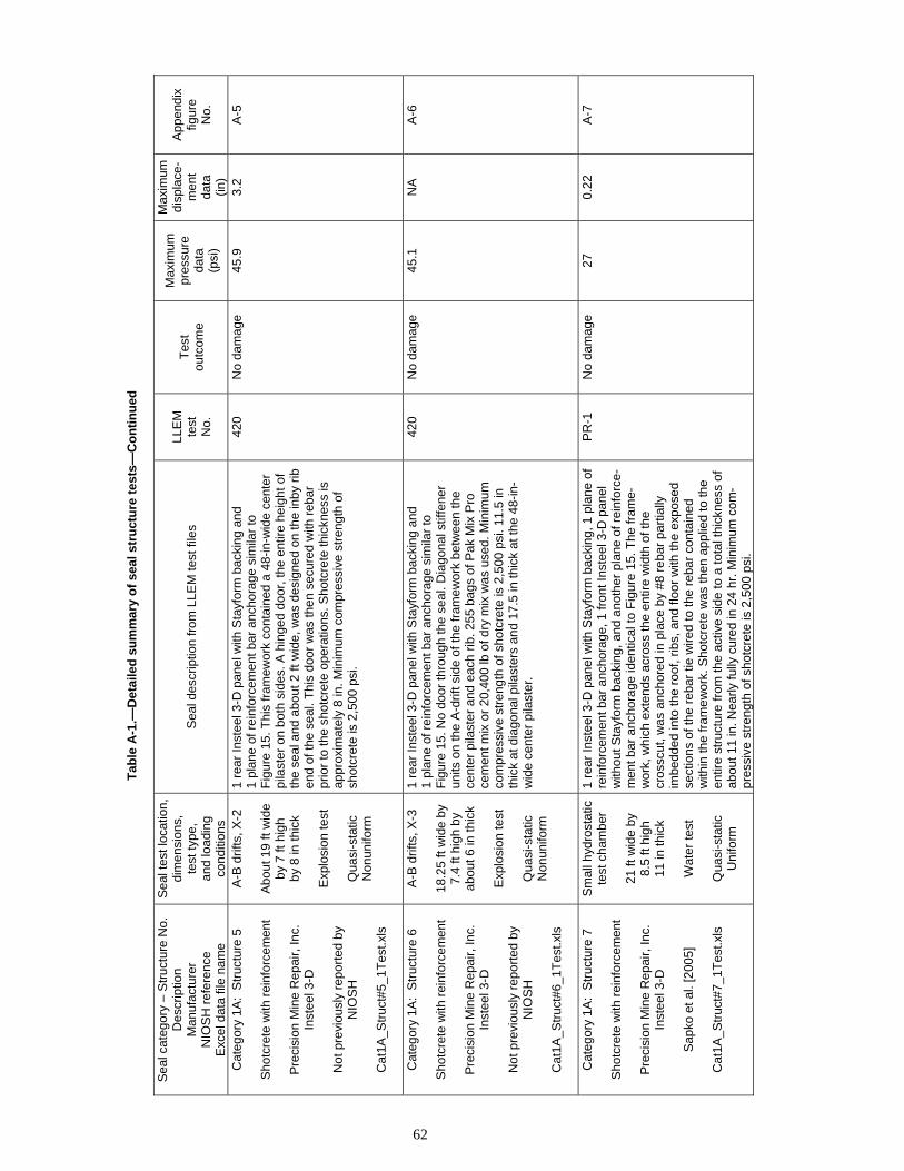
Tab
le A
-1.—
Det
aile
d s
um
mar
y o
f se
al s
tru
ctu
re t
ests
—C
on
tin
ued
Sea
l cat
egor
y –
Str
uctu
re N
o.
Des
crip
tion
Man
ufac
ture
rN
IOS
H r
efer
ence
E
xcel
dat
a fil
e na
me
Sea
l tes
t loc
atio
n,
dim
ensi
ons,
te
st ty
pe,
and
load
ing
cond
ition
s
Sea
l des
crip
tion
from
LLE
M te
st fi
les
LLE
Mte
stN
o.
Tes
tou
tcom
e
Max
imum
pr
essu
reda
ta(p
si)
Max
imum
disp
lace
- m
ent
data
(in)
App
endi
xfig
ure
No.
Cat
egor
y 1A
: S
truc
ture
5
Sho
tcre
te w
ith r
einf
orce
men
t
Pre
cisi
on M
ine
Rep
air,
Inc.
In
stee
l 3-D
Not
pre
viou
sly
repo
rted
by
NIO
SH
Cat
1A_S
truc
t#5_
1Tes
t.xls
A-B
drif
ts, X
-2
Abo
ut 1
9 ft
wid
e b
y 7
ft hi
gh
by
8 in
thic
k
Exp
losi
on te
st
Qua
si-s
tatic
Non
unifo
rm
1 re
ar In
stee
l 3-D
pan
el w
ith S
tayf
orm
bac
king
and
1
plan
e of
rei
nfor
cem
ent b
ar a
ncho
rage
sim
ilar
to
Fig
ure
15. T
his
fram
ewor
k co
ntai
ned
a 48
-in-w
ide
cent
er
pila
ster
on
both
sid
es. A
hin
ged
door
, the
ent
ire h
eigh
t of
the
seal
and
abo
ut 2
ft w
ide,
was
des
igne
d on
the
inby
rib
en
d of
the
seal
. Thi
s do
or w
as t
hen
secu
red
with
reb
ar
prio
r to
the
shot
cret
e op
erat
ions
. Sho
tcre
te th
ickn
ess
is
appr
oxim
atel
y 8
in. M
inim
um c
ompr
essi
ve s
tren
gth
of
shot
cret
e is
2,5
00 p
si.
420
No
dam
age
45.9
3.
2 A
-5
Cat
egor
y 1A
: S
truc
ture
6
Sho
tcre
te w
ith r
einf
orce
men
t
Pre
cisi
on M
ine
Rep
air,
Inc.
In
stee
l 3-D
Not
pre
viou
sly
repo
rted
by
NIO
SH
Cat
1A_S
truc
t#6_
1Tes
t.xls
A-B
drif
ts, X
-3
18.2
5 ft
wid
e b
y7.
4 ft
high
by
abou
t 6 in
thic
k
Exp
losi
on te
st
Qua
si-s
tatic
Non
unifo
rm
1 re
ar In
stee
l 3-D
pan
el w
ith S
tayf
orm
bac
king
and
1
plan
e of
rei
nfor
cem
ent b
ar a
ncho
rage
sim
ilar
to
Fig
ure
15. N
o do
or th
roug
h th
e se
al. D
iago
nal s
tiffe
ner
units
on
the
A-d
rift s
ide
of th
e fr
amew
ork
betw
een
the
cent
er p
ilast
er a
nd e
ach
rib. 2
55 b
ags
of P
ak M
ix P
ro
cem
ent m
ix o
r 2
0,40
0 lb
of d
ry m
ix w
as u
sed.
Min
imum
co
mpr
essi
ve s
tren
gth
of s
hotc
rete
is 2
,500
psi
. 11.
5 in
th
ick
at d
iago
nal p
ilast
ers
and
17.5
in th
ick
at th
e 48
-in
wid
e ce
nter
pila
ster
.
420
No
dam
age
45.1
N
A
A-6
Cat
egor
y 1A
: S
truc
ture
7
Sho
tcre
te w
ith r
einf
orce
men
t
Pre
cisi
on M
ine
Rep
air,
Inc.
In
stee
l 3-D
Sap
ko e
t al.
[200
5]
Cat
1A_S
truc
t#7_
1Tes
t.xls
Sm
all h
ydro
stat
ic
test
cha
mbe
r
21 ft
wid
e b
y8.
5 ft
high
11 in
thic
k
Wat
er te
st
Qua
si-s
tatic
Uni
form
1 re
ar In
stee
l 3-D
pan
el w
ith S
tayf
orm
bac
king
, 1 p
lane
of
rein
forc
emen
t bar
anc
hora
ge, 1
fron
t In
stee
l 3-D
pan
el
with
out S
tayf
orm
bac
king
, and
ano
ther
pla
ne o
f rei
nfor
ce
men
t bar
anc
hora
ge id
entic
al to
Fig
ure
15. T
he fr
ame
wor
k, w
hich
ext
ends
acr
oss
the
entir
e w
idth
of t
he
cros
scut
, was
anc
hore
d in
pla
ce b
y #8
reb
ar p
artia
llyim
bedd
ed in
to th
e ro
of, r
ibs,
and
floo
r w
ith t
he e
xpos
ed
sect
ions
of t
he r
ebar
tie
wire
d to
the
reba
r co
ntai
ned
with
in th
e fr
ame
wor
k. S
hotc
rete
was
then
app
lied
to th
e en
tire
stru
ctur
e fr
om th
e ac
tive
side
to a
tota
l thi
ckne
ss o
f ab
out 1
1 in
. Nea
rly fu
lly c
ured
in 2
4 hr
. Min
imum
com
pr
essi
ve s
tren
gth
of s
hotc
rete
is 2
,500
psi
.
PR
-1
No
dam
age
27
0.22
A
-7
62

Tab
le A
-1.—
Det
aile
d s
um
mar
y o
f se
al s
tru
ctu
re t
ests
—C
on
tin
ued
Sea
l cat
egor
y –
Str
uctu
re N
o.
Des
crip
tion
Man
ufac
ture
rN
IOS
H r
efer
ence
E
xcel
dat
a fil
e na
me
Sea
l tes
t loc
atio
n,
dim
ensi
ons,
te
st ty
pe,
and
load
ing
cond
ition
s
Sea
l des
crip
tion
from
LLE
M te
st fi
les
LLE
Mte
stN
o.
Tes
tou
tcom
e
Max
imum
pr
essu
reda
ta(p
si)
Max
imum
disp
lace
- m
ent
data
(in)
App
endi
xfig
ure
No.
CA
TE
GO
RY
1B
SE
AL
S
Con
cret
e or
con
cret
elik
e m
ater
ials
with
inte
rnal
ste
el r
einf
orce
men
t and
anc
hora
ge to
roc
k M
eshb
lock
sea
l: S
hotc
rete
with
rei
nfor
cem
ent,
6 st
ruct
ures
test
ed
Cat
egor
y 1B
: S
truc
ture
1
Pum
ped
conc
rete
like
mat
eria
ls
with
rei
nfor
cem
ent
R. G
. Joh
nson
Co.
, Inc
.A
quab
lend
plu
g se
al b
etw
een
Gun
mes
h st
oppi
ngs
Wei
ss e
t al.
[199
9]
Cat
1B_S
truc
t#1_
16T
est.x
ls
B-C
drif
ts, X
-1
17.8
ft w
ide
by
6.4
ft hi
gh b
y4
ft th
ick
Exp
losi
on te
sts
Qua
si-s
tatic
Non
unifo
rm
4-ft-
thic
k se
al s
imila
r in
con
cept
to F
igur
e 20
with
2
rein
forc
ed G
unm
esh
wal
ls s
pra
yed
with
app
roxi
mat
ely
0.5-
in-t
hick
coa
ting
of M
B-5
00 (
4,20
0-ps
i com
pres
sive
st
reng
th m
ater
ial)
and
1 pl
ane
of a
ncho
red
stee
l re
info
rcem
ent b
ar. A
quab
lend
inje
cted
bet
wee
n fo
rm w
alls
(5
53-p
si c
ompr
essi
ve s
tren
gth
mat
eria
l). B
olts
em
bedd
ed
24 in
into
roo
f/flo
or/r
ibs
with
24
in e
xten
ding
into
ent
ry.
Ver
tical
tie-
in b
olts
bet
wee
n ro
of a
nd fl
oor
bolts
.
347
No
dam
age
27.0
N
A
A-8
34
8 N
o da
mag
e 52
.5
NA
34
9 N
o da
mag
e 87
.7
NA
35
0 N
o da
mag
e 4
NA
35
1 N
o da
mag
e 0.
5 N
A
A-9
35
2, 3
53
No
dam
age
—
NA
35
4 N
o da
mag
e 35
.7
NA
35
5 N
o da
mag
e 25
.3
NA
35
6, 3
57
No
dam
age
—
NA
35
8 N
o da
mag
e 4.
2 N
A
359
No
dam
age
35.9
N
A
A-1
0 36
0 N
o da
mag
e 97
.4
NA
36
1 N
o da
mag
e 0.
5 N
A
362
No
dam
age
6.2
NA
36
3 N
o da
mag
e 10
.0
NA
A
-11
364
No
dam
age
39.1
N
A
365
No
dam
age
39.6
N
A
366
No
dam
age
25.7
N
A
Cat
egor
y 1B
: S
truc
ture
2
Pum
ped
conc
rete
like
mat
eria
ls
with
rei
nfor
cem
ent
R. G
. Joh
nson
Co.
, Inc
.M
eshb
lock
Wei
ss e
t al.
[199
9]
Cat
1B_S
truc
t#2_
5Tes
t.xls
B-C
drif
ts, X
-2
18.9
ft w
ide
by
7.4
ft hi
gh b
y13
in th
ick
Exp
losi
on te
sts
Qua
si-s
tatic
Non
unifo
rm
12-in
-thi
ck s
eal p
lus
1-in
-thi
ck c
oatin
g id
entic
al to
F
igur
e 20
. Sta
cked
Mes
hblo
ck b
aske
ts s
ecur
ed w
ith b
olts
an
chor
ed 2
4 in
into
roo
f/flo
or/r
ibs.
Spr
aye
d M
B-5
00 m
ate
rial (
desi
gn 4
,200
psi
) in
to M
eshb
lock
bas
kets
. 5,4
60-p
si
com
pres
sive
str
engt
h af
ter
7-da
y cu
re a
nd 6
,61
0 ps
i afte
r 28
-day
cur
e. S
eal t
este
d on
day
s 12
, 19,
27,
40,
and
41.
347
No
dam
age
36.1
N
A
A-1
2 34
8 N
o da
mag
e 60
.0
NA
34
9 N
o da
mag
e 78
.7
NA
35
0 N
o da
mag
e 4
NA
A
-13
351
Des
troy
ed
6 N
A
63
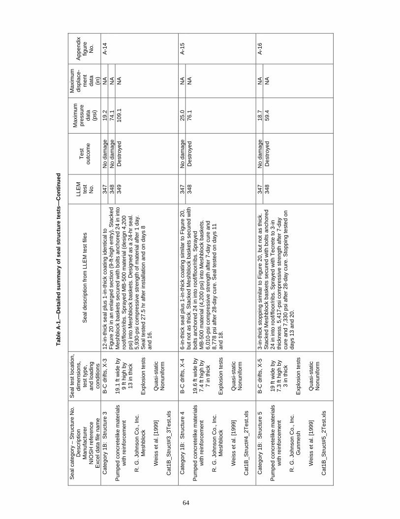
Tab
le A
-1.—
Det
aile
d s
um
mar
y o
f se
al s
tru
ctu
re t
ests
—C
on
tin
ued
Sea
l cat
egor
y –
Str
uctu
re N
o.
Des
crip
tion
Man
ufac
ture
rN
IOS
H r
efer
ence
E
xcel
dat
a fil
e na
me
Sea
l tes
t loc
atio
n,
dim
ensi
ons,
te
st ty
pe,
and
load
ing
cond
ition
s
Sea
l des
crip
tion
from
LLE
M te
st fi
les
LLE
Mte
stN
o.
Tes
tou
tcom
e
Max
imum
pr
essu
reda
ta(p
si)
Max
imum
di
spla
ce-
men
tda
ta(in
)
App
endi
xfig
ure
No.
Cat
egor
y 1B
: S
truc
ture
3
Pum
ped
conc
rete
like
mat
eria
ls
with
rei
nfor
cem
ent
R. G
. Joh
nson
Co.
, Inc
.M
eshb
lock
Wei
ss e
t al.
[199
9]
Cat
1B_S
truc
t#3_
3Tes
t.xls
B-C
drif
ts, X
-3
19.1
ft w
ide
by
9 ft
high
by
13 in
thic
k
Exp
losi
on te
sts
Qua
si-s
tatic
Non
unifo
rm
12-in
-thi
ck s
eal p
lus
1-in
-thi
ck c
oatin
g id
entic
al to
F
igur
e 20
in a
n en
larg
ed s
ectio
n (9
-ft-
high
ent
ry).
Sta
cked
M
eshb
lock
bas
kets
sec
ured
with
bol
ts a
ncho
red
24 in
into
ro
of/fl
oor/
ribs.
Spr
aye
d M
B-5
00 m
ater
ial (
desi
gn 4
,200
ps
i) in
to M
eshb
lock
bas
kets
. Des
igne
d as
a 2
4-hr
sea
l. 5,
930-
psi c
ompr
essi
ve s
tren
gth
of m
ater
ial a
fter
1 da
y.S
eal t
este
d 27
.5 h
r af
ter
inst
alla
tion
and
on d
ays
8 an
d 16
.
347
No
dam
age
19.2
N
A
A-1
4 34
8 N
o da
mag
e 74
.1
NA
34
9 D
estr
oyed
10
9.1
NA
Cat
egor
y 1B
: S
truc
ture
4
Pum
ped
conc
rete
like
mat
eria
ls
with
rei
nfor
cem
ent
R. G
. Joh
nson
Co.
, Inc
.M
eshb
lock
Wei
ss e
t al.
[199
9]
Cat
1B_S
truc
t#4_
2Tes
t.xls
B-C
drif
ts, X
-4
19.6
ft w
ide
by
7.4
ft hi
gh b
y7
in th
ick
Exp
losi
on te
sts
Qua
si-s
tatic
Non
unifo
rm
6-in
-thi
ck s
eal p
lus
1-in
-thi
ck c
oatin
g si
mila
r to
Fig
ure
20,
but n
ot a
s th
ick.
Sta
cked
Mes
hblo
ck b
aske
ts s
ecur
ed w
ith
bolts
anc
hore
d 24
in in
to r
oof/f
loor
/rib
s. S
pray
ed
MB
-500
mat
eria
l (4,
200
psi)
into
Mes
hblo
ck b
aske
ts.
6,01
0-ps
i com
pres
sive
str
engt
h af
ter
7-da
y cu
re a
nd
8,77
8 ps
i afte
r 28
-day
cur
e. S
eal t
este
d on
day
s 11
an
d 18
.
347
No
dam
age
25.0
N
A
A-1
5 34
8 D
estr
oyed
76
.1
NA
Cat
egor
y 1B
: S
truc
ture
5
Pum
ped
conc
rete
like
mat
eria
ls
with
rei
nfor
cem
ent
R. G
. Joh
nson
Co.
, Inc
.G
unm
esh
Wei
ss e
t al.
[199
9]
Cat
1B_S
truc
t#5_
2Tes
t.xls
B-C
drif
ts, X
-5
19 ft
wid
e b
y7.
3 ft
high
by
3 in
thic
k
Exp
losi
on te
sts
Qua
si-s
tatic
Non
unifo
rm
3-in
-thi
ck s
topp
ing
sim
ilar
to F
igur
e 20
, but
not
as
thic
k.
Sta
cked
Mes
hblo
ck b
aske
ts s
ecur
ed w
ith b
olts
anc
hore
d 24
in in
to r
oof/f
loor
/rib
s. S
pray
ed
with
Tec
rete
to 3
-inth
ickn
ess.
5,4
17-p
si c
ompr
essi
ve s
tren
gth
afte
r 7-
day
cure
and
7,3
30 p
si a
fter
28-d
ay c
ure.
Sto
ppin
g te
sted
on
days
13
and
20.
347
No
dam
age
18.7
N
A
A-1
6 34
8 D
estr
oyed
59
.4
NA
64

Tab
le A
-1.—
Det
aile
d s
um
mar
y o
f se
al s
tru
ctu
re t
ests
—C
on
tin
ued
Sea
l cat
egor
y –
Str
uctu
re N
o.
Des
crip
tion
Man
ufac
ture
rN
IOS
H r
efer
ence
E
xcel
dat
a fil
e na
me
Sea
l tes
t loc
atio
n,
dim
ensi
ons,
te
st ty
pe,
and
load
ing
cond
ition
s
Sea
l des
crip
tion
from
LLE
M te
st fi
les
LLE
Mte
stN
o.
Tes
tou
tcom
e
Max
imum
pr
essu
reda
ta(p
si)
Max
imum
di
spla
ce-
men
tda
ta(in
)
App
endi
xfig
ure
No.
Cat
egor
y 1B
: S
truc
ture
6
Pum
ped
conc
rete
like
mat
eria
ls
with
rei
nfor
cem
ent
R. G
. Joh
nson
Co.
, Inc
.G
unm
esh
Wei
ss e
t al.
[199
9]
Cat
1B_S
truc
t#6_
2Tes
t.xls
B-C
drif
ts, X
-3
19.3
ft w
ide
by
6.9
ft hi
gh b
y1.
75 in
thic
k
Exp
losi
on te
sts
Qua
si-s
tatic
Non
unifo
rm
1.75
-in-t
hick
sto
ppin
g si
mila
r to
Fig
ure
20, b
ut n
ot a
s th
ick.
Con
stru
cted
with
rei
nfor
ced
Gun
mes
h sc
reen
s an
d sp
raye
d w
ith M
B-5
00 (
4,20
0 ps
i) an
d T
ecre
te. A
ncho
red
with
bol
ts e
mbe
dded
24
in in
to r
oof/f
loor
/rib
s w
ith 2
4 in
ex
tend
ing
into
ent
ry. V
ertic
al ti
e-in
rei
nfor
cing
bar
s be
twee
n ro
of a
nd
floor
bol
ts. N
o sa
mpl
es ta
ken
for
com
pres
sive
str
engt
h te
stin
g. S
topp
ing
test
ed o
n da
ys 7
an
d 8.
350
No
dam
age
3 N
A
A-1
7 35
1 D
estr
oyed
6
NA
CA
TE
GO
RY
2A
SE
AL
S
Pum
pabl
e ce
men
titio
us m
ater
ials
with
no
stee
l rei
nfor
cem
ent a
nd n
o hi
tchi
ng a
nd w
ith a
nd w
ithou
t car
bon
fiber
ret
rofit
C
ompr
essi
ve s
tren
gth
of 2
00 p
si a
nd g
reat
er t
han
48 in
thic
k, 4
str
uctu
res
test
ed
Cat
egor
y 2A
: S
truc
ture
1
Pum
pabl
e ce
men
titio
us m
ater
ial
with
Bla
stse
al
Sea
l ret
rofit
by
Tra
nsco
Min
e S
ervi
ces
Co.
Wei
ss a
nd H
arte
is [2
008]
Cat
2A_
Str
uct#
1_2T
est.x
ls
C d
rift a
t 320
ftfr
om c
lose
d en
d
18.7
ft w
ide
by
7.3
ft hi
gh b
y5.
1 ft
thic
k
Exp
losi
on te
sts
Ref
lect
ed
Uni
form
A 4
-ft-
thic
k pu
mpa
ble
cem
entit
ious
sea
l sim
ilar
to
Fig
ure
23. C
elus
eal m
ater
ial w
as u
sed
with
a 1
00-
to
190-
psi (
143-
psi a
vera
ge)
com
pres
sive
str
engt
h at
36
day
s. A
13-
in-t
hick
ret
rofit
str
uctu
re u
sing
a s
olid
co
ncre
te-b
lock
wal
l, po
lyur
etha
ne, c
arbo
n fib
er-r
einf
orce
d po
lym
er, a
nd h
eavy
ste
el a
ngle
iron
rei
nfor
cem
ent a
cros
s th
e ro
of a
nd fl
oor
was
inst
alle
d ag
ains
t the
pum
pabl
e se
al
on th
e no
nexp
losi
on s
ide.
508
No
dam
age
66
0.60
A
-18
509
Des
troy
ed
195.
5 >
5.77
A
-19
Cat
egor
y 2A
: S
truc
ture
2
Pum
pabl
e ce
men
titio
us m
ater
ial
seal
R. G
. Joh
nson
Co.
, Inc
.
Sap
ko e
t al.
[200
5]
Cat
2A_S
truc
t#2_
1Tes
t.xls
Sm
all h
ydro
stat
ic
test
cha
mbe
r
21.2
ft w
ide
by
8.7
ft hi
gh b
y4
ft th
ick
Met
hane
igni
tion
test
Qua
si-s
tatic
Uni
form
4-ft-
thic
k pu
mpa
ble
cem
entit
ious
foam
sea
l sim
ilar
to
Fig
ure
23.
350-
psi ±
75-p
si c
ompr
essi
ve s
tren
gth.
Met
hane
igni
tion
test
.
C3-
44E
D
estr
oyed
32
>
3 A
-20
65

Tab
le A
-1.—
Det
aile
d s
um
mar
y o
f se
al s
tru
ctu
re t
ests
—C
on
tin
ued
Sea
l cat
egor
y –
Str
uctu
re N
o.
Des
crip
tion
Man
ufac
ture
rN
IOS
H r
efer
ence
E
xcel
dat
a fil
e na
me
Sea
l tes
t loc
atio
n,
dim
ensi
ons,
te
st ty
pe,
and
load
ing
cond
ition
s
Sea
l des
crip
tion
from
LLE
M te
st fi
les
LLE
Mte
stN
o.
Tes
tou
tcom
e
Max
imum
pr
essu
reda
ta(p
si)
Max
imum
di
spla
ce-
men
tda
ta(in
)
App
endi
xfig
ure
No.
Cat
egor
y 2A
: S
truc
ture
3
Pum
pabl
e ce
men
titio
us m
ater
ial
seal
R. G
. Joh
nson
Co.
, Inc
.
Sap
ko e
t al.
[200
5]
Cat
2A_S
truc
t#3_
3Tes
t.xls
Sm
all h
ydro
stat
ic
test
cha
mbe
r
21.2
ft w
ide
by
8.7
ft hi
gh b
y4
ft th
ick
Wat
er te
sts
Qua
si-s
tatic
Uni
form
4-ft-
thic
k pu
mpa
ble
cem
entit
ious
foam
sea
l sim
ilar
to
Fig
ure
23.
350-
psi ±
75-p
si c
ompr
essi
ve s
tren
gth.
Hyd
rost
atic
test
.
C7-
64W
N
o da
mag
e 21
0.
35
A-2
1C
7-68
W
No
dam
age
30.5
1.
0 A
-22
C7-
70W
N
o da
mag
e 25
0.
65
A-2
3
Cat
egor
y 2A
: S
truc
ture
4
Pum
pabl
e ce
men
titio
us m
ater
ial
seal
R. G
. Joh
nson
Co.
, Inc
.
Sap
ko e
t al.
[200
5]
Cat
2A_S
truc
t#4_
1Tes
t.xls
Larg
e hy
dros
tatic
te
st c
ham
ber
30.8
ft w
ide
by
15.6
ft h
igh
by
4 ft
thic
k
Met
hane
igni
tion
test
Qua
si-s
tatic
Uni
form
4-ft-
thic
k pu
mpa
ble
cem
entit
ious
foam
sea
l sim
ilar
to
Fig
ure
23.
350-
psi ±
75-p
si c
ompr
essi
ve s
tren
gth.
Met
hane
igni
tion
test
.
L2-5
1E
Des
troy
ed
27.5
>
3 A
-24
CA
TE
GO
RY
2B
SE
AL
S
Pum
pabl
e ce
men
titio
us m
ater
ials
with
no
stee
l rei
nfor
cem
ent a
nd n
o hi
tchi
ngC
ompr
essi
ve s
tren
gth
of 4
33 p
si a
nd g
reat
er th
an 3
6 in
thic
k, 1
str
uctu
re te
sted
C
ateg
ory
2B:
Str
uctu
re 1
Pum
pabl
e ce
men
titio
us m
ater
ial
>36
in
Hei
Tec
h C
orp.
R
ibfil
l
Wei
ss e
t al.
[200
2]
Cat
2B_
Str
uct#
1_2T
est.x
ls
B-C
drif
ts, X
-3
19.4
ft w
ide
by
6.9
ft hi
gh b
y36
in th
ick
Exp
losi
on te
sts
Qua
si-s
tatic
Non
unifo
rm
36-in
-thi
ck p
umpa
ble
seal
sim
ilar
to F
igur
e 23
. A
ppro
xim
ate
com
pres
sive
str
engt
h of
450
–500
psi
. 35
4 N
o da
mag
e 37
.9
NA
A
-25
355
No
dam
age
32.5
N
A
66
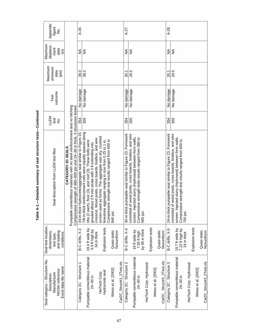
Tab
le A
-1.—
Det
aile
d s
um
mar
y o
f se
al s
tru
ctu
re t
ests
—C
on
tin
ued
Sea
l cat
egor
y –
Str
uctu
re N
o.
Des
crip
tion
Man
ufac
ture
rN
IOS
H r
efer
ence
E
xcel
dat
a fil
e na
me
Sea
l tes
t loc
atio
n,
dim
ensi
ons,
te
st ty
pe,
and
load
ing
cond
ition
s
Sea
l des
crip
tion
from
LLE
M te
st fi
les
LLE
Mte
stN
o.
Tes
tou
tcom
e
Max
imum
pr
essu
reda
ta(p
si)
Max
imum
di
spla
ce-
men
tda
ta(in
)
App
endi
xfig
ure
No.
CA
TE
GO
RY
2C
SE
AL
S
Pum
pabl
e ce
men
titio
us m
ater
ials
with
no
stee
l rei
nfor
cem
ent a
nd n
o hi
tchi
ngC
ompr
essi
ve s
tren
gth
of 4
80–6
00 p
si a
nd 2
4–30
in th
ick,
4 s
truc
ture
s te
sted
C
ateg
ory
2C:
Str
uctu
re 1
Pum
pabl
e ce
men
titio
us m
ater
ial
24–3
0 in
Hei
Tec
h C
orp.
H
ydro
cret
e se
al
Wei
ss e
t al.
[200
2]
Cat
2C_S
truc
t#1_
2Tes
t.xls
B-C
drif
ts, X
-2
19.4
ft w
ide
by
6.9
ft hi
gh b
y34
in th
ick
Exp
losi
on te
sts
Qua
si-s
tatic
Non
unifo
rm
34-in
-thi
ck H
ydro
cret
e/ag
greg
ate
seal
sim
ilar
to F
igur
e 23
. 7/
8-in
-thi
ck r
einf
orce
men
t rod
s w
ere
equa
lly s
pace
d al
ong
ribs
(2 e
ach)
, flo
or (
3), a
nd r
oof
(3).
The
se b
olts
wer
e gr
oute
d ab
out 3
ft in
to s
trat
a w
ith 3
ft e
xten
ding
into
cr
ossc
ut. W
ood
post
s, c
ross
boa
rds,
bra
ttice
, and
wire
sc
reen
use
d as
form
s. T
he a
ggre
gate
was
dry
, cr
ushe
d lim
esto
ne a
ggre
gate
ran
ging
in s
ize
from
0.2
5 to
1 in
. C
ompr
essi
ve s
tren
gth
test
res
ults
ran
ged
from
600
to
840
psi.
354
No
dam
age
36.0
N
A
A-2
6 35
5 N
o da
mag
e 38
.2
NA
Cat
egor
y 2C
: S
truc
ture
2
Pum
pabl
e ce
men
titio
us m
ater
ial
24–3
0 in
Hei
Tec
h C
orp.
Hyd
rose
al
Wei
ss e
t al.
[200
2]
Cat
2C_
Str
uct#
2_2T
est.x
ls
B-C
drif
ts, X
-4
19 ft
wid
e b
y7.
55 ft
hig
hb
y 30
in th
ick
Exp
losi
on te
sts
Qua
si-s
tatic
Non
unifo
rm
30-in
-thi
ck p
umpa
ble
seal
sim
ilar
to F
igur
e 23
. For
mw
ork
cons
iste
d of
woo
d po
sts,
cro
ss b
oard
s, b
ratti
ce, a
nd w
ire
scre
en. I
njec
ted
slur
ry (
Hyd
rose
al)
betw
een
form
wal
ls.
Com
pres
sive
str
engt
h te
sts
resu
lts r
ange
d fr
om 3
90 to
56
5 ps
i.
354
No
dam
age
30.1
N
A
A-2
7 35
5 N
o da
mag
e 28
.5
NA
Cat
egor
y 2C
: S
truc
ture
3
Pum
pabl
e ce
men
titio
us m
ater
ial
24–3
0 in
Hei
Tec
h C
orp.
Hyd
rose
al
Wei
ss e
t al.
[200
2]
Cat
2C_S
truc
t#3_
2Tes
t.xls
B-C
drif
ts, X
-5
19.7
ft w
ide
by
7.22
ft h
igh
by
24 in
thic
k
Exp
losi
on te
sts
Qua
si-s
tatic
Non
unifo
rm
24-in
-thi
ck p
umpa
ble
seal
sim
ilar
to F
igur
e 23
. For
mw
ork
cons
iste
d of
woo
d po
sts,
cro
ss b
oard
s, b
ratti
ce, a
nd w
ire
scre
en. I
njec
ted
slur
ry (
Hyd
rose
al)
betw
een
form
wal
ls.
Com
pres
sive
str
engt
h te
st r
esul
ts r
ange
d fr
om 6
00 to
75
0 ps
i.
354
No
dam
age
30.1
N
A
A-2
8 35
5 N
o da
mag
e 28
.5
NA
67

Tab
le A
-1.—
Det
aile
d s
um
mar
y o
f se
al s
tru
ctu
re t
ests
—C
on
tin
ued
Sea
l cat
egor
y –
Str
uctu
re N
o.
Des
crip
tion
Man
ufac
ture
rN
IOS
H r
efer
ence
E
xcel
dat
a fil
e na
me
Sea
l tes
t loc
atio
n,
dim
ensi
ons,
te
st ty
pe,
and
load
ing
cond
ition
s
Sea
l des
crip
tion
from
LLE
M te
st fi
les
LLE
Mte
stN
o.
Tes
tou
tcom
e
Max
imum
pr
essu
reda
ta(p
si)
Max
imum
di
spla
ce-
men
tda
ta(in
)
App
endi
xfig
ure
No.
Cat
egor
y 2C
: S
truc
ture
4
Pum
pabl
e ce
men
titio
us m
ater
ial
24–3
0 in
Hei
Tec
h C
orp.
rap
id-c
onst
ruct
ion
colu
mn
bag
pum
pabl
e se
al
Wei
ss e
t al.
[200
2]
Cat
2C_
Str
uct#
4_4T
est.x
ls
B-C
drif
ts, X
-2
19 ft
wid
e b
y6.
75 ft
hig
h b
y30
in th
ick
Exp
losi
on te
sts
Qua
si-s
tatic
Non
unifo
rm
30-in
-thi
ck H
eiT
ech
grou
t col
umn
seal
con
sist
ing
of s
ix30
-in-d
iam
rei
nfor
ced
brat
tice
bag
colu
mns
spa
ced
acro
ss
the
cros
scut
with
8-
to 1
8-in
gap
s be
twee
n ba
gs a
nd r
ibs.
B
ags
wer
e fil
led
with
600
- to
80
0-ps
i com
pres
sive
st
reng
th p
umpa
ble
cem
entit
ious
slu
rry,
whi
ch h
arde
ns
with
in 1
0 m
in a
nd is
nea
rly fu
lly c
ured
in 2
4 hr
. Sim
ilar
bags
with
out t
he
rein
forc
emen
t wer
e th
en in
stal
led
betw
een
the
colu
mns
and
fille
d w
ith t
he s
ame
grou
t. 59
7-ps
i ±63
-psi
com
pres
sive
str
engt
h af
ter
13 d
ays
. T
est 1
con
duct
ed 1
0 da
ys a
fter
cons
truc
tion.
No
hitc
hing
. P
olyu
reth
ane
foam
(S
ilent
Sea
l) w
as s
pra
yed
arou
nd th
e se
al p
erim
eter
and
bet
wee
n th
e co
lum
ns fr
om th
e B
-drif
t si
de.
403
No
dam
age
20.8
1.
14
A-2
9 40
4 N
o da
mag
e 28
.7
2.14
A
-30
405
No
dam
age
26.7
0.
11
A-3
1 40
6 D
amag
ed
35.4
>
3.2
A-3
2
CA
TE
GO
RY
3A
SE
AL
S
Art
icul
ated
str
uctu
res:
Sol
id a
nd h
ollo
w-c
ore
con
cret
e bl
ocks
with
or
with
out
hitc
hing
S
tand
ard
solid
-con
cret
e-bl
ock
seal
with
hitc
hing
, 7 s
truc
ture
s te
sted
C
ateg
ory
3A:
Str
uctu
re 1
Sta
ndar
d se
al w
ith h
itchi
ng
NIO
SH
con
stru
cted
Sap
ko e
t al.
[200
5]
Cat
3A_S
truc
t#1_
4Tes
t.xls
B-C
drif
ts, X
-1
18.3
ft w
ide
by
6.7
ft hi
gh b
y16
in th
ick
Exp
losi
on te
sts
Qua
si-s
tatic
Non
unifo
rm
Sta
ndar
d so
lid-c
oncr
ete-
bloc
k se
al w
ithou
t pila
ster
sim
ilar
to F
igur
e 26
. Sim
ulat
ed r
ib a
nd fl
oor
hitc
hing
with
6-in
by
6-in
by
0.5-
in-t
hick
ste
el a
ngle
anc
hore
d on
18-
in c
ente
rs
usin
g 1-
in-d
iam
by
9-in
-long
Hilt
i Kw
ik B
olt I
II. F
ully
mor
ta
red
and
stag
gere
d jo
ints
.
403
No
dam
age
18.1
0.
00
A-3
3 40
4 N
o da
mag
e 22
.4
0.00
A
-34
405
No
dam
age
28.3
0.
00
A-3
5 40
6 N
o da
mag
e 30
.8
0.10
A
-36
68

Tab
le A
-1.—
Det
aile
d s
um
mar
y o
f se
al s
tru
ctu
re t
ests
—C
on
tin
ued
Sea
l cat
egor
y –
Str
uctu
re N
o.
Des
crip
tion
Man
ufac
ture
rN
IOS
H r
efer
ence
E
xcel
dat
a fil
e na
me
Sea
l tes
t loc
atio
n,
dim
ensi
ons,
te
st ty
pe,
and
load
ing
cond
ition
s
Sea
l des
crip
tion
from
LLE
M te
st fi
les
LLE
Mte
stN
o.
Tes
tou
tcom
e
Max
imum
pr
essu
reda
ta(p
si)
Max
imum
di
spla
ce-
men
tda
ta(in
)
App
endi
xfig
ure
No.
Cat
egor
y 3A
: S
truc
ture
2
Sta
ndar
d se
al w
ith h
itchi
ng
NIO
SH
con
stru
cted
Not
pre
viou
sly
repo
rted
by
NIO
SH
Cat
3A_S
truc
t#2_
10T
est.x
ls
B-C
drif
ts, X
-1
18.3
ft w
ide
by
6.7
ft hi
gh b
y16
in th
ick
Exp
losi
on te
sts
Qua
si-s
tatic
Non
unifo
rm
Sta
ndar
d so
lid-c
oncr
ete-
bloc
k se
al w
ith 1
6-in
-wid
e b
y32
-in-t
hick
cen
ter
pila
ster
iden
tical
to F
igur
e 26
. Sim
ulat
ed
rib a
nd fl
oor
hitc
hing
with
6-in
by
6-in
by
0.5-
in-t
hick
ste
el
angl
e an
chor
ed o
n 18
-in c
ente
rs u
sing
1-in
-dia
m b
y 9-
in
long
Hilt
i Kw
ik B
olt I
II. Q
uikr
ete
Blo
cBon
d (1
225-
51)
was
us
ed a
s m
orta
r.
500
No
dam
age
23
NA
A
-37
501
No
dam
age
22
NA
50
2 N
o da
mag
e 22
N
A
503
No
dam
age
15
NA
50
4 N
o da
mag
e 16
N
A
505
No
dam
age
24
NA
50
6 N
o da
mag
e 34
N
A
A-3
8 50
7 N
o da
mag
e 24
N
A
508
No
dam
age
22
NA
50
9 N
o da
mag
e 46
N
A
Cat
egor
y 3A
: S
truc
ture
3
Sta
ndar
d se
al w
ith h
itchi
ng
NIO
SH
con
stru
cted
Not
pre
viou
sly
repo
rted
by
NIO
SH
Cat
3A_S
truc
t#3_
2Tes
t.xls
B-C
drif
ts, X
-3
18.6
ft w
ide
by
6.8
ft hi
gh b
y16
in th
ick
Exp
losi
on te
sts
Qua
si-s
tatic
Non
unifo
rm
Sta
ndar
d so
lid-c
oncr
ete-
bloc
k se
al w
ith 1
6-in
-wid
e b
y32
-in-t
hick
cen
ter
pila
ster
iden
tical
to F
igur
e 26
. Use
d T
ype
S m
orta
r a
nd B
-bon
d fa
ce c
oatin
gs. S
imul
ated
rib
an
d flo
or h
itchi
ng w
ith 6
-in b
y 6-
in b
y 0.
5-in
-thi
ck s
teel
an
gle
anch
ored
on
18-in
cen
ters
usi
ng 1
-in-d
iam
by
9-in
-long
Hilt
i Kw
ik B
olt I
II.
506
No
dam
age
63
0.11
A
-39
507
No
dam
age
30
0.07
A
-40
Cat
egor
y 3A
: S
truc
ture
4
Sta
ndar
d se
al w
ith h
itchi
ng
NIO
SH
con
stru
cted
Sap
ko e
t al.
[200
5]
Cat
3A_S
truc
t#4_
5Tes
t.xls
Sm
all h
ydro
stat
ic
test
cha
mbe
r
16.8
ft w
ide
by
8.6
ft hi
gh b
y16
in th
ick
Met
hane
igni
tion
test
s
Qua
si-s
tatic
Un
iform
Sta
ndar
d so
lid-c
oncr
ete-
bloc
k se
al id
entic
al to
Fig
ure
26.
2,50
0 ps
i (±1
00-p
si)
conc
rete
blo
cks.
16-
in-w
ide
by
32-in
th
ick
pila
ster
. Sim
ulat
ed r
ib a
nd fl
oor
hitc
hing
with
6-in
by
6-in
by
0.5-
in-t
hick
ste
el a
ngle
anc
hore
d on
18-
in c
ente
rs
usin
g 1-
in-d
iam
by
9-in
-long
Hilt
i Kw
ik B
olt I
II. M
etha
ne
igni
tion
test
s.
C1-
5E
No
dam
age
56.5
0.
13
A-4
1 C
1-8E
N
o da
mag
e 90
.1
NA
A
-42
C1-
9E
No
dam
age
94.3
0.
22
A-4
3 C
1-10
E
No
dam
age
79.5
0.
21
A-4
4 C
1-11
E
Des
troy
ed
99.7
>
2.8
A-4
5
69

Tab
le A
-1.—
Det
aile
d s
um
mar
y o
f se
al s
tru
ctu
re t
ests
—C
on
tin
ued
Sea
l cat
egor
y –
Str
uctu
re N
o.
Des
crip
tion
Man
ufac
ture
rN
IOS
H r
efer
ence
E
xcel
dat
a fil
e na
me
Sea
l tes
t loc
atio
n,
dim
ensi
ons,
te
st ty
pe,
and
load
ing
cond
ition
s
Sea
l des
crip
tion
from
LLE
M te
st fi
les
LLE
Mte
stN
o.
Tes
tou
tcom
e
Max
imum
pr
essu
reda
ta(p
si)
Max
imum
di
spla
ce-
men
tda
ta(in
)
App
endi
xfig
ure
No.
Cat
egor
y 3A
: S
truc
ture
5
Sta
ndar
d se
al w
ith h
itchi
ng
NIO
SH
con
stru
cted
Sap
ko e
t al.
[200
5]
Cat
3A_S
truc
t#5_
2Tes
t.xls
Sm
all h
ydro
stat
ic
test
cha
mbe
r
16.8
ft w
ide
by
8.6
ft hi
gh b
y16
in th
ick
Wat
er a
ndm
etha
ne ig
nitio
nte
sts
Qua
si-s
tatic
Uni
form
Sta
ndar
d so
lid-c
oncr
ete-
bloc
k se
al id
entic
al to
Fig
ure
26.
2,50
0-ps
i (±1
00-p
si)
conc
rete
blo
cks.
16-
in-w
ide
by
32-in
th
ick
pila
ster
. Sim
ulat
ed r
ib a
nd fl
oor
hitc
hing
with
6-in
by
6-in
by
0.5-
in-t
hick
ste
el a
ngle
anc
hore
d on
18-
in c
ente
rs
usin
g 1-
in-d
iam
by
9-in
-long
Hilt
i Kw
ik B
olt I
II. M
etha
ne
igni
tion
and
hydr
osta
tic te
sts.
C6-
60W
N
o da
mag
e 32
0.
024
A-4
6 C
6-62
E
No
dam
age
88
0.25
A
-47
Cat
egor
y 3A
: S
truc
ture
6
Sta
ndar
d se
al w
ith h
itchi
ng
NIO
SH
con
stru
cted
Sap
ko e
t al.
[200
5]
Cat
3A_S
truc
t#6_
1Tes
t.xls
Larg
e hy
dros
tatic
te
st c
ham
ber
28 ft
wid
e b
y15
.5 ft
hig
h b
y16
in th
ick
Met
hane
igni
tion
test
Qua
si-s
tatic
Un
iform
Sta
ndar
d so
lid-c
oncr
ete-
bloc
k se
al id
entic
al to
Fig
ure
26.
2,50
0-ps
i (±1
00-p
si)
conc
rete
blo
cks.
16-
in-w
ide
by
32-in
th
ick
pila
ster
. Sim
ulat
ed r
ib a
nd fl
oor
hitc
hing
with
6-in
by
6-in
by
0.5-
in-t
hick
ste
el a
ngle
anc
hore
d on
18-
in c
ente
rs
usin
g 1-
in-d
iam
by
9-in
-long
Hilt
i Kw
ik B
olt I
II. M
etha
ne
igni
tion
test
.
L1-3
7E
Des
troy
ed
32
>3
A-4
8
Cat
egor
y 3A
: S
truc
ture
7
Sta
ndar
d se
al w
ith h
itchi
ng
NIO
SH
con
stru
cted
Sap
ko e
t al.
[200
5]
Cat
3A_S
truc
t#7_
1Tes
t.xls
SR
CM
hyd
rost
atic
te
st c
ham
ber
18 ft
wid
e b
y6.
2 ft
high
by
16 in
thic
k
Wat
er te
st
Qua
si-s
tatic
Un
iform
Sta
ndar
d so
lid-c
oncr
ete-
bloc
k se
al id
entic
al to
Fig
ure
26.
1,90
0- to
2,5
00-p
si (
±100
-psi
) co
ncre
te b
lock
s. 1
6-in
-wid
e b
y 32
-in-t
hick
pila
ster
. Sim
ulat
ed r
ib a
nd fl
oor
hitc
hing
w
ith 6
-in b
y 6-
in b
y 0.
5-in
-thi
ck s
teel
ang
le a
ncho
red
on
18-in
cen
ters
usi
ng 1
-in-d
iam
by
9-in
-long
Hilt
i Kw
ik B
olt
III. H
ydro
stat
ic te
st.
SR
CM
-1
Des
troy
ed
20
0.15
A
-49
70

Tab
le A
-1.—
Det
aile
d s
um
mar
y o
f se
al s
tru
ctu
re t
ests
—C
on
tin
ued
Sea
l cat
egor
y –
Str
uctu
re N
o.
Des
crip
tion
Man
ufac
ture
rN
IOS
H r
efer
ence
E
xcel
dat
a fil
e na
me
Sea
l tes
t loc
atio
n,
dim
ensi
ons,
te
st ty
pe,
and
load
ing
cond
ition
s
Sea
l des
crip
tion
from
LLE
M te
st fi
les
LLE
Mte
stN
o.
Tes
tou
tcom
e
Max
imum
pr
essu
reda
ta(p
si)
Max
imum
di
spla
ce-
men
tda
ta(in
)
App
endi
xfig
ure
No.
CA
TE
GO
RY
3B
SE
AL
S
Art
icul
ated
str
uctu
res:
Sol
id a
nd h
ollo
w-c
ore
con
cret
e bl
ocks
with
or
with
out
hitc
hing
S
olid
-con
cret
e-bl
ock
seal
with
Pac
kset
ter
Bag
s an
d w
ithou
t hitc
hing
, 3 s
truc
ture
s te
sted
C
ateg
ory
3B:
Str
uctu
re 1
Sta
ndar
d se
al w
ith g
rout
bag
s
Str
ata
Min
e S
ervi
ces
Pac
kset
ter
seal
s
Wei
ss e
t al.
[200
2]
Cat
3B_S
truc
t#1_
2Tes
t.xls
B-C
drif
ts, X
-2
19 ft
wid
e b
y6.
9 ft
high
by
16 in
thic
k
Exp
losi
on te
sts
Qua
si-s
tatic
Non
unifo
rm
Sta
ndar
d so
lid-c
oncr
ete-
bloc
k se
al s
imila
r to
Fig
ure
30
with
cen
ter
pila
ster
and
floo
r hi
tchi
ng s
imul
ated
by
stee
l an
gle.
Use
d to
ngue
-and
-gro
ove,
8-in
sol
id b
lock
s w
ith
fully
mor
tare
d jo
ints
and
face
coa
tings
. Pac
kset
ter
Bag
s fr
om S
trat
a P
rodu
cts
used
on
roof
and
rib
s to
elim
inat
e ne
ed fo
r rib
hitc
hing
in fr
iabl
e rib
con
ditio
ns. P
acks
ette
r B
ags
pres
sure
d to
44
psi.
Com
pres
sive
str
engt
h of
gro
ut
in b
ags
is 3
60 p
si a
fter
1 da
y, 4
35 p
si a
fter
7 da
ys, a
nd
580
psi a
fter
28 d
ays.
365
No
dam
age
33.9
N
A
A-5
0 36
6 N
o da
mag
e —
N
A
Cat
egor
y 3B
: S
truc
ture
2
Sta
ndar
d se
al w
ith g
rout
bag
s
Str
ata
Min
e S
ervi
ces
Pac
kset
ter
seal
s
Wei
ss e
t al.
[200
2]
Cat
3B_S
truc
t#2_
2Tes
t.xls
B-C
drif
ts, X
-3
19.4
ft w
ide
by
6.9
ft hi
gh b
y16
in th
ick
Exp
losi
on te
sts
Qua
si-s
tatic
Non
unifo
rm
Sta
ndar
d so
lid-c
oncr
ete-
bloc
k se
al id
entic
al to
Fig
ure
30w
ith c
ente
r pi
last
er. N
o flo
or h
itchi
ng s
imul
ated
by
stee
l an
gle.
Use
d to
ngue
-and
-gro
ove,
8-in
sol
id b
lock
s w
ith
fully
mor
tare
d jo
ints
and
face
coa
tings
. Pac
kset
ter
Bag
s fr
om S
trat
a P
rodu
cts
used
on
roof
and
rib
s to
elim
inat
e ne
ed fo
r rib
hitc
hing
in fr
iabl
e rib
con
ditio
ns. P
acks
ette
r B
ags
pres
sure
d to
36–
40 p
si. C
ompr
essi
ve s
tren
gth
of
grou
t in
bags
is 3
60 p
si a
fter
1 da
y, 4
35 p
si a
fter
7 da
ys,
and
580
psi a
fter
28 d
ays
.
365
No
dam
age
49.5
N
A
A-5
1 36
6 N
o da
mag
e 40
.4
NA
Cat
egor
y 3B
: S
truc
ture
3
Sta
ndar
d se
al w
ith g
rout
bag
s
Str
ata
Min
e S
ervi
ces
Pac
kset
ter
seal
s
Wei
ss e
t al.
[200
2]
Cat
3B_
Str
uct#
3_2T
est.x
ls
B-C
drif
ts, X
-4
19 ft
wid
e b
y7.
2 ft
high
by
16 in
thic
k
Exp
losi
on te
sts
Qua
si-s
tatic
Non
unifo
rm
Sta
ndar
d so
lid-c
oncr
ete-
bloc
k se
al w
ith c
ente
r pi
last
er
sim
ilar
to F
igur
e 30
. No
floor
hitc
hing
sim
ulat
ed b
y st
eel
angl
e. U
sed
tong
ue-a
nd-g
roov
e, 8
-in s
olid
blo
cks
that
w
ere
dry-
stac
ked
with
fac
e co
atin
gs. P
acks
ette
r B
ags
from
Str
ata
Pro
duct
s us
ed o
n ro
of a
nd r
ibs
to e
limin
ate
need
for
rib h
itchi
ng in
fria
ble
rib c
ondi
tions
. Pac
kset
ter
Bag
s pr
essu
red
to 4
4 ps
i. C
ompr
essi
ve s
tren
gth
of g
rout
in
bag
s is
360
psi
afte
r 1
day,
435
psi
afte
r 7
days
, and
58
0 ps
i afte
r 28
day
s.
365
No
dam
age
31.7
N
A
A-5
2 36
6 D
estr
oyed
41
.6
NA
71

Tab
le A
-1.—
Det
aile
d s
um
mar
y o
f se
al s
tru
ctu
re t
ests
—C
on
tin
ued
Sea
l cat
egor
y –
Str
uctu
re N
o.
Des
crip
tion
Man
ufac
ture
rN
IOS
H r
efer
ence
E
xcel
dat
a fil
e na
me
Sea
l tes
t loc
atio
n,
dim
ensi
ons,
te
st ty
pe,
and
load
ing
cond
ition
s
Sea
l des
crip
tion
from
LLE
M te
st fi
les
LLE
Mte
stN
o.
Tes
tou
tcom
e
Max
imum
pr
essu
reda
ta(p
si)
Max
imum
di
spla
ce-
men
tda
ta(in
)
App
endi
xfig
ure
No.
CA
TE
GO
RY
3C
SE
AL
S
Art
icul
ated
str
uctu
res:
Sol
id a
nd h
ollo
w-c
ore
con
cret
e bl
ocks
with
or
with
out
hitc
hing
V
entil
atio
n st
oppi
ngs:
Sol
id a
nd h
ollo
w-c
ore
conc
rete
blo
cks
with
out h
itchi
ng, 8
str
uctu
res
test
ed
Cat
egor
y 3C
: S
truc
ture
1
Ven
tilat
ion
stop
ping
: H
ollo
w-c
ore
conc
rete
blo
ck
NIO
SH
con
stru
cted
Wei
ss e
t al.
[200
8]
Cat
3C_S
truc
t#1_
2Tes
t.xls
B-C
drif
ts, X
-4
18.9
ft w
ide
by
7.1
ft hi
gh b
y6
in th
ick
Exp
losi
on te
sts
Qua
si-s
tatic
Non
unifo
rm
Dry
-sta
cked
, sta
gger
ed-jo
int,
hollo
w-c
ore
conc
rete
blo
ck
stop
ping
iden
tical
to F
igur
e 32
on
smal
l con
cret
e fo
unda
tio
n lo
cate
d ab
out 5
ft fr
om t
he c
ente
r of
the
cros
scut
to
war
d B
-drif
t. M
orta
r us
ed to
leve
l the
firs
t blo
ck c
ours
e.
3-co
re, c
oncr
ete
bloc
k w
ith n
omin
al d
imen
sion
s of
6 in
by
8 in
by
16 in
and
1,0
00-p
si c
ompr
essi
ve s
tren
gth.
Woo
d w
edge
s us
ed to
tigh
ten
each
cou
rse
at th
e rib
s an
d w
ood
head
er b
oard
s an
d w
edge
s w
ere
used
acr
oss
the
inte
rfa
ce o
f the
top
cour
se to
the
min
e ro
of to
tigh
ten
the
stop
pi
ng. Q
uikr
ete
Blo
cBon
d se
alan
t (N
o. 1
227-
50; M
SH
A
IC 3
6) a
pplie
d to
bot
h fa
ces
of e
ach
stop
ping
.
427
No
dam
age
0.60
0.
00
A-5
3 42
8 D
estr
oyed
4.
0 >
3.5
A-5
4
Cat
egor
y 3C
: S
truc
ture
2
Ven
tilat
ion
stop
ping
: H
ollo
w-c
ore
conc
rete
blo
ck
NIO
SH
con
stru
cted
Wei
ss e
t al.
[200
8]
Cat
3C_S
truc
t#2_
2Tes
t.xls
B-C
drif
ts, X
-5
18.8
ft w
ide
by
7.3
ft hi
gh b
y6
in th
ick
Exp
losi
on te
sts
Qua
si-s
tatic
Non
unifo
rm
Dry
-sta
cked
, sta
gger
ed-jo
int,
hollo
w-c
ore
conc
rete
blo
ck
stop
ping
iden
tical
to F
igur
e 32
on
smal
l con
cret
e fo
unda
tio
n lo
cate
d ab
out 5
ft fr
om t
he c
ente
r of
the
cros
scut
to
war
d B
-drif
t. M
orta
r us
ed to
leve
l the
firs
t blo
ck c
ours
e.
3-co
re, c
oncr
ete
bloc
k w
ith n
omin
al d
imen
sion
s of
6 in
by
8 in
by
16 in
and
1,0
00-p
si c
ompr
essi
ve s
tren
gth.
Woo
d w
edge
s us
ed to
tigh
ten
each
cou
rse
at th
e rib
s an
d w
ood
head
er b
oard
s an
d w
edge
s w
ere
used
acr
oss
the
inte
rfa
ce o
f the
top
cour
se to
the
min
e ro
of to
tigh
ten
the
stop
pi
ng. Q
uikr
ete
Blo
cBon
d se
alan
t (N
o. 1
227-
50; M
SH
A
IC 3
6) a
pplie
d to
bot
h fa
ces
of e
ach
stop
ping
.
427
No
dam
age
0.60
0.
00
A-5
5 42
8 D
estr
oyed
4.
0 >
3.5
A-5
6
72

Tab
le A
-1.—
Det
aile
d s
um
mar
y o
f se
al s
tru
ctu
re t
ests
—C
on
tin
ued
Sea
l cat
egor
y –
Str
uctu
re N
o.
Des
crip
tion
Man
ufac
ture
rN
IOS
H r
efer
ence
E
xcel
dat
a fil
e na
me
Sea
l tes
t loc
atio
n,
dim
ensi
ons,
te
st ty
pe,
and
load
ing
cond
ition
s
Sea
l des
crip
tion
from
LLE
M te
st fi
les
LLE
Mte
stN
o.
Tes
tou
tcom
e
Max
imum
pr
essu
reda
ta(p
si)
Max
imum
di
spla
ce-
men
tda
ta(in
)
App
endi
xfig
ure
No.
Cat
egor
y 3C
: S
truc
ture
3
Ven
tilat
ion
stop
ping
: H
ollo
w-c
ore
conc
rete
blo
ck
NIO
SH
con
stru
cted
Wei
ss e
t al.
[200
8]
Cat
3C_S
truc
t#3_
6Tes
t.xls
B-C
drif
ts, X
-6
17.2
ft w
ide
by
7.1
ft hi
gh b
y6
in th
ick
Exp
losi
on te
sts
Qua
si-s
tatic
Non
unifo
rm
Dry
-sta
cked
, sta
gger
ed-jo
int,
hollo
w-c
ore
conc
rete
blo
ck
stop
ping
iden
tical
to F
igur
e 32
on
smal
l con
cret
e fo
unda
tio
n lo
cate
d ab
out 5
ft fr
om t
he c
ente
r of
the
cros
scut
to
war
d B
-drif
t. M
orta
r us
ed to
leve
l the
firs
t blo
ck c
ours
e.
3-co
re, c
oncr
ete
bloc
k w
ith n
omin
al d
imen
sion
s of
6 in
by
8 in
by
16 in
with
1,0
00-p
si c
ompr
essi
ve s
tren
gth.
Woo
d w
edge
s us
ed to
tigh
ten
each
cou
rse
at th
e rib
s an
d w
ood
head
er b
oard
s an
d w
edge
s w
ere
used
acr
oss
the
inte
rfa
ce o
f the
top
cour
se to
the
min
e ro
of to
tigh
ten
the
stop
pi
ng. Q
uikr
ete
Blo
cBon
d se
alan
t (N
o. 1
227-
50; M
SH
A
IC 3
6) a
pplie
d to
bot
h fa
ces
of e
ach
stop
ping
.
427
No
dam
age
0.50
0.
00
A-5
7 42
8 N
o da
mag
e 3.
2 0.
01
A-5
8 42
9 N
o da
mag
e 1.
2 0.
15
A-5
9 43
0 D
amag
ed
3.2
1.0
A-6
0 43
2 D
amag
ed
1.8
1.5
A-6
1 43
3 D
estr
oyed
3.
2 >
4.0
A-6
2
Cat
egor
y 3C
: S
truc
ture
4
Ven
tilat
ion
stop
ping
: H
ollo
w-c
ore
conc
rete
blo
ck
NIO
SH
con
stru
cted
Wei
ss e
t al.
[200
8]
Cat
3C_S
truc
t#4_
7Tes
t.xls
B-C
drif
ts, X
-7
16.8
ft w
ide
by
7.3
ft hi
gh b
y6
in th
ick
Exp
losi
on te
sts
Qua
si-s
tatic
Non
unifo
rm
Dry
-sta
cked
, sta
gger
ed-jo
int,
hollo
w-c
ore
conc
rete
blo
ck
stop
ping
iden
tical
to F
igur
e 32
on
smal
l con
cret
e fo
unda
tio
n lo
cate
d ab
out 5
ft fr
om t
he c
ente
r of
the
cros
scut
to
war
d B
-drif
t. M
orta
r us
ed to
leve
l the
firs
t blo
ck c
ours
e.
3-co
re, c
oncr
ete
bloc
k w
ith n
omin
al d
imen
sion
s of
6 in
by
8 in
by
16 in
with
1,0
00-p
si c
ompr
essi
ve s
tren
gth.
Woo
d w
edge
s us
ed to
tigh
ten
each
cou
rse
at th
e rib
s an
d w
ood
head
er b
oard
s an
d w
edge
s w
ere
used
acr
oss
the
inte
rfa
ce o
f the
top
cour
se to
the
min
e ro
of to
tigh
ten
the
stop
ping
. Qui
kret
e B
locB
ond
seal
ant (
No.
122
7-50
; MS
HA
IC
36)
app
lied
to b
oth
face
s of
eac
h st
oppi
ng.
427
No
dam
age
0.6
0.04
A
-63
428
No
dam
age
3.5
0.19
A
-64
429
No
dam
age
1.0
0.13
A
-65
430
No
dam
age
2.6
0.34
A
-66
432
No
dam
age
1.5
0.43
A
-67
433
No
dam
age
3.0
0.68
A
-68
434
Dam
aged
2.
5 0.
93
A-6
9
Cat
egor
y 3C
: S
truc
ture
5
Ven
tilat
ion
stop
ping
: S
olid
con
cret
e bl
ock
NIO
SH
con
stru
cted
Wei
ss e
t al.
[200
8]
Cat
3C_S
truc
t#5_
6Tes
t.xls
B-C
drif
ts, X
-4
18.9
ft w
ide
by
7.1
ft hi
gh b
y6
in th
ick
Exp
losi
on te
sts
Qua
si-s
tatic
Non
unifo
rm
Dry
-sta
cked
, sta
gger
ed-jo
int,
solid
-con
cret
e-bl
ock
stop
pi
ng id
entic
al to
Fig
ure
32 o
n sm
all c
oncr
ete
foun
datio
n lo
cate
d ab
out 5
ft fr
om th
e ce
nter
of t
he c
ross
cut t
ow
ard
B-d
rift.
Mor
tar
use
d to
leve
l the
firs
t blo
ck c
ours
e. S
tand
ar
d so
lid c
oncr
ete
bloc
k w
ith n
omin
al d
imen
sion
s of
6 in
b
y 8
in b
y 16
in a
nd 1
,300
- to
1,7
40-p
si c
ompr
essi
ve
stre
ngth
. Woo
d w
edge
s us
ed to
tigh
ten
each
cou
rse
at
the
ribs
and
wo
od h
eade
r bo
ards
and
wed
ges
wer
e us
ed
acro
ss th
e in
terf
ace
of th
e to
p co
urse
to th
e m
ine
roof
to
tigh
ten
the
stop
ping
. Qui
kret
e B
locB
ond
seal
ant
(No.
122
7-50
; MS
HA
IC 3
6) a
pplie
d to
bot
h fa
ces
of e
ach
stop
ping
.
457
No
dam
age
0.80
0.
00
A-7
0 45
8 N
o da
mag
e 1.
60
0.06
A
-71
459
No
dam
age
4.7
0.67
A
-72
460
Dam
aged
7.
5 1.
15
A-7
3 46
1 D
amag
ed
4.2
0.60
A
-74
462
Des
troy
ed
7.7
>3.
00
A-7
5
73

Tab
le A
-1.—
Det
aile
d s
um
mar
y o
f se
al s
tru
ctu
re t
ests
—C
on
tin
ued
Sea
l cat
egor
y –
Str
uctu
re N
o.
Des
crip
tion
Man
ufac
ture
rN
IOS
H r
efer
ence
E
xcel
dat
a fil
e na
me
Sea
l tes
t loc
atio
n,
dim
ensi
ons,
te
st ty
pe,
and
load
ing
cond
ition
s
Sea
l des
crip
tion
from
LLE
M te
st fi
les
LLE
Mte
stN
o.
Tes
tou
tcom
e
Max
imum
pr
essu
reda
ta(p
si)
Max
imum
di
spla
ce-
men
tda
ta(in
)
App
endi
xfig
ure
No.
Cat
egor
y 3C
: S
truc
ture
6
Ven
tilat
ion
stop
ping
: S
olid
con
cret
e bl
ock
NIO
SH
con
stru
cted
Wei
ss e
t al.
[200
8]
Cat
3C_S
truc
t#6_
7Tes
t.xls
B-C
drif
ts, X
-5
18.8
ft w
ide
by
7.3
ft hi
gh b
y6
in th
ick
Exp
losi
on te
sts
Qua
si-s
tatic
Non
unifo
rm
Dry
-sta
cked
, sta
gger
ed-jo
int,
solid
-con
cret
e-bl
ock
stop
pi
ng id
entic
al to
Fig
ure
32 o
n sm
all c
oncr
ete
foun
datio
n lo
cate
d ab
out 5
ft fr
om th
e ce
nter
of t
he c
ross
cut t
ow
ard
B-d
rift.
Mor
tar
use
d to
leve
l the
firs
t blo
ck c
ours
e. S
tand
ar
d so
lid c
oncr
ete
bloc
k w
ith n
omin
al d
imen
sion
s of
6 in
b
y 8
in b
y 16
in a
nd 1
,300
- to
1,7
40-p
si c
ompr
essi
ve
stre
ngth
). W
ood
wed
ges
used
to ti
ghte
n ea
ch c
ours
e at
th
e rib
s an
d w
ood
hea
der
boar
ds a
nd w
edge
s w
ere
used
ac
ross
the
inte
rfac
e of
the
top
cour
se to
the
min
e ro
of
to ti
ghte
n th
e st
oppi
ng. Q
uikr
ete
Blo
cBon
d se
alan
t (N
o. 1
227-
50; M
SH
A IC
36)
app
lied
to b
oth
face
s of
eac
h st
oppi
ng.
457
No
dam
age
0.75
0.
00
A-7
6 45
8 N
o da
mag
e 1.
4 0.
05
A-7
7 45
9 N
o da
mag
e 3.
7 0.
41
A-7
8 46
0 N
o da
mag
e 5.
4 0.
76
A-7
9 46
1 N
o da
mag
e 3.
9 0.
32
A-8
0 46
2 N
o da
mag
e 6.
7 0.
93
A-8
1 46
3 D
estr
oyed
19
.5
>3.
2 A
-82
Cat
egor
y 3C
: S
truc
ture
7
Ven
tilat
ion
stop
ping
: S
olid
con
cret
e bl
ock
NIO
SH
con
stru
cted
Wei
ss e
t al.
[200
8]
Cat
3C_S
truc
t#7_
10T
est.x
ls
A-B
drif
ts, X
-6
19.1
ft w
ide
by
7.6
ft hi
gh b
y8
in th
ick
Exp
losi
on te
sts
Qua
si-s
tatic
Non
unifo
rm
8-in
-thi
ck, s
olid
-con
cret
e-bl
ock
stop
ping
iden
tical
to
Fig
ure
32 w
ith fu
lly m
orta
red
(Typ
e S
) jo
ints
. Qui
kret
e B
-Bon
d (N
o. 1
227-
50)
appl
ied
0.25
in th
ick
on A
-drif
t fac
e.
Thi
s st
oppi
ng is
loca
ted
appr
oxim
atel
y 10
ft in
to th
e cr
oss
cut a
s m
easu
red
from
the
A-d
rift r
ib li
ne.
510
No
dam
age
16.8
N
A
A-8
3 51
1 N
o da
mag
e 12
.1
NA
51
2 N
o da
mag
e 12
.2
NA
51
3 N
o da
mag
e 11
.3
NA
A
-84
514
No
dam
age
18.1
N
A
515
No
dam
age
14.8
N
A
516
No
dam
age
19.6
N
A
A-8
5 51
7 N
o da
mag
e 16
.1
NA
51
8 N
o da
mag
e 13
.7
NA
51
9 N
o da
mag
e 41
.1
NA
C
ateg
ory
3C:
Str
uctu
re 8
Ven
tilat
ion
stop
ping
: S
olid
con
cret
e bl
ock
NIO
SH
con
stru
cted
Wei
ss e
t al.
[200
8]
Cat
3C_S
truc
t#8_
10T
est.x
ls
A-B
drif
ts, X
-7
19.5
ft w
ide
by
7.4
ft hi
gh b
y6
in th
ick
Exp
losi
on te
sts
Qua
si-s
tatic
Non
unifo
rm
6-in
-thi
ck, s
olid
-con
cret
e-bl
ock
stop
ping
iden
tical
to
Fig
ure
32 w
ith fu
lly m
orta
red
(Typ
e S
) jo
ints
. Qui
kret
e B
-Bon
d (N
o. 1
227-
50)
appl
ied
0.25
in th
ick
on A
-drif
t fac
e.
Thi
s st
oppi
ng is
loca
ted
appr
oxim
atel
y 10
ft in
to th
e cr
oss
cut a
s m
easu
red
from
the
A-d
rift r
ib li
ne.
510
No
dam
age
19.1
0.
51
A-8
6 51
1 N
o da
mag
e 11
.0
0.41
A
-87
512
No
dam
age
11.2
0.
45
A-8
8 51
3 N
o da
mag
e 11
.3
0.47
A
-89
514
No
dam
age
12.2
0.
54
A-9
0 51
5 N
o da
mag
e 17
.5
0.72
A
-91
516
No
dam
age
14.4
0.
68
A-9
2 51
7 N
o da
mag
e 15
.3
0.74
A
-93
518
No
dam
age
12.0
0.
74
A-9
4 51
9 D
estr
oyed
28
.8
2.76
A
-95
74
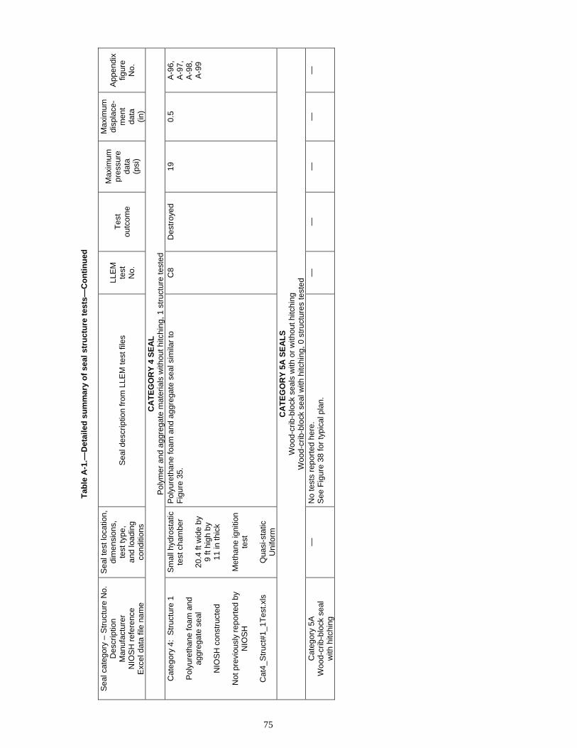
Tab
le A
-1.—
Det
aile
d s
um
mar
y o
f se
al s
tru
ctu
re t
ests
—C
on
tin
ued
Sea
l cat
egor
y –
Str
uctu
re N
o.
Des
crip
tion
Man
ufac
ture
rN
IOS
H r
efer
ence
E
xcel
dat
a fil
e na
me
Sea
l tes
t loc
atio
n,
dim
ensi
ons,
te
st ty
pe,
and
load
ing
cond
ition
s
Sea
l des
crip
tion
from
LLE
M te
st fi
les
LLE
Mte
stN
o.
Tes
tou
tcom
e
Max
imum
pr
essu
reda
ta(p
si)
Max
imum
di
spla
ce-
men
tda
ta(in
)
App
endi
xfig
ure
No.
CA
TE
GO
RY
4 S
EA
L
Pol
ymer
and
agg
rega
te m
ater
ials
with
out h
itchi
ng, 1
str
uctu
re te
sted
C
ateg
ory
4: S
truc
ture
1
Pol
yure
than
e fo
am a
nd
aggr
egat
e se
al
NIO
SH
con
stru
cted
Not
pre
viou
sly
repo
rted
by
NIO
SH
Cat
4_S
truc
t#1_
1Tes
t.xls
Sm
all h
ydro
stat
ic
test
cha
mbe
r
20.4
ft w
ide
by
9 ft
high
by
11 in
thic
k
Met
hane
igni
tion
test
Qua
si-s
tatic
Uni
form
Pol
yure
than
e fo
am a
nd a
ggre
gate
sea
l sim
ilar
toF
igur
e 35
. C
8 D
estr
oyed
19
0.
5 A
-96,
A-9
7,A
-98,
A-9
9
CA
TE
GO
RY
5A
SE
AL
S
Woo
d-cr
ib-b
lock
sea
ls w
ith o
r w
ithou
t hitc
hing
W
ood-
crib
-blo
ck s
eal w
ith h
itchi
ng, 0
str
uctu
res
test
ed
Cat
egor
y 5A
W
ood-
crib
-blo
ck s
eal
with
hitc
hing
—
No
test
s re
port
ed h
ere.
See
Fig
ure
38 fo
r ty
pica
l pla
n.
—
—
—
—
—
75

Tab
le A
-1.—
Det
aile
d s
um
mar
y o
f se
al s
tru
ctu
re t
ests
—C
on
tin
ued
Sea
l cat
egor
y –
Str
uctu
re N
o.
Des
crip
tion
Man
ufac
ture
rN
IOS
H r
efer
ence
E
xcel
dat
a fil
e na
me
Sea
l tes
t loc
atio
n,
dim
ensi
ons,
te
st ty
pe,
and
load
ing
cond
ition
s
Sea
l des
crip
tion
from
LLE
M te
st fi
les
LLE
Mte
stN
o.
Tes
tou
tcom
e
Max
imum
pr
essu
reda
ta(p
si)
Max
imum
di
spla
ce-
men
tda
ta(in
)
App
endi
xfig
ure
No.
CA
TE
GO
RY
5B
SE
AL
S
Woo
d-cr
ib-b
lock
sea
ls w
ith o
r w
ithou
t hitc
hing
W
ood-
crib
-blo
ck s
eal w
ith g
lue
and
Pac
kset
ter
Bag
s, 1
str
uctu
re t
este
d C
ateg
ory
5B:
Str
uctu
re 1
Woo
d-cr
ib-b
lock
sea
l with
glu
e an
d P
acks
ette
r B
ags
Str
ata
Min
e S
ervi
ces
woo
d bl
ock
seal
with
P
acks
ette
r B
ags
Sap
ko e
t al.
[200
3]
Cat
5B_S
truc
t#1_
2Tes
t.xls
B-C
drif
ts, X
-1
18.4
ft w
ide
by
6.5
ft hi
gh b
y30
in th
ick
Exp
losi
on te
sts
Qua
si-s
tatic
Non
unifo
rm
30-in
-thi
ck s
eal i
dent
ical
to F
igur
e 41
usi
ng 5
-in b
y 6-
in b
y30
-in-lo
ng E
aste
rn O
ak c
rib b
lock
s. T
he w
ood
bloc
ks
wer
e in
stal
led
on a
leve
l con
cret
e pa
d le
ngth
wis
e pa
ralle
l w
ith t
he c
ross
cut r
ibs.
Alte
rnat
ing
cour
ses
with
the
5- o
r 6-
in d
imen
sion
s of
the
crib
in th
e ve
rtic
al d
imen
sion
to
achi
eve
a st
agge
red
join
t pat
tern
. App
roxi
mat
ely
36–4
0 bl
ocks
per
cou
rse,
14
cour
ses
high
and
abo
ut
550
bloc
ks to
tal.
3 be
ads
of a
dhes
ive
appl
ied
betw
een
the
bloc
ks a
nd b
lock
cou
rses
. 12
Pac
kset
ter
Bag
s in
stal
led
and
inje
cted
with
gro
ut to
abo
ut 6
0 ps
i alo
ng th
e m
ine
roof
an
d rib
s. C
ompr
essi
ve s
tren
gth
of g
rout
in b
ags
is 3
60 p
si
afte
r 1
day,
435
psi
afte
r 7
days
, and
580
psi
afte
r 28
day
s. H
itchi
ng a
long
the
floor
and
rib
s w
as n
ot u
sed.
P
olyu
reth
ane
foam
was
inje
cted
into
the
gaps
bet
wee
n th
e P
acks
ette
r B
ags
and
the
min
e st
rata
/blo
ck in
terf
ace.
E
ach
side
was
spr
ay-c
oate
d w
ith E
agle
sea
lant
; bra
ttice
cu
rtai
n w
as in
stal
led
acro
ss th
e B
-drif
t fac
e an
d sp
raye
d w
ith t
he s
eala
nt. T
este
d 14
day
s af
ter
cons
truc
tion.
396
No
dam
age
23.2
0.
79
A-1
00
399
No
dam
age
32.4
1.
9 A
-101
CA
TE
GO
RY
6A
SE
AL
S
Art
icul
ated
str
uctu
res:
Lig
htw
eigh
t blo
cks
with
or
with
out h
itchi
ng
Ligh
twei
ght b
lock
s: 2
4 in
thic
k w
ith h
itchi
ng, 2
str
uctu
res
test
ed
Cat
egor
y 6
A:
Str
uctu
re 1
Om
ega
bloc
ksw
ith h
itchi
ng
Bur
rell
Min
ing
Pro
duct
s O
meg
a bl
ock
seal
Cas
hdol
lar
et a
l. [2
007]
Cat
6A_S
truc
t#1_
2Tes
t.xls
B-C
drif
ts, X
-3
18.8
ft w
ide
by
6.75
ft h
igh
by
24 in
thic
k
Exp
losi
on te
sts
Qua
si-s
tatic
Non
unifo
rm
24-in
-thi
ck O
meg
a bl
ock
seal
iden
tical
to F
igur
e 44
with
fu
lly m
orta
red
join
ts (
Qui
kret
e B
locB
ond)
, a 4
8-in
by
48-in
inte
rlock
ed c
ente
r pi
last
er, a
nd s
imul
ated
hitc
h in
to
the
ribs
and
floor
with
6-in
by
6-in
by
0.5-
in-t
hick
ste
el
angl
e bo
lted
to th
e rib
s an
d flo
or.
508
No
dam
age
52.9
0.
04
A-1
02
509
Dam
aged
70
2.
2 A
-103
76

Tab
le A
-1.—
Det
aile
d s
um
mar
y o
f se
al s
tru
ctu
re t
ests
—C
on
tin
ued
Sea
l cat
egor
y –
Str
uctu
re N
o.
Des
crip
tion
Man
ufac
ture
rN
IOS
H r
efer
ence
E
xcel
dat
a fil
e na
me
Sea
l tes
t loc
atio
n,
dim
ensi
ons,
te
st ty
pe,
and
load
ing
cond
ition
s
Sea
l des
crip
tion
from
LLE
M te
st fi
les
LLE
Mte
stN
o.
Tes
tou
tcom
e
Max
imum
pr
essu
reda
ta(p
si)
Max
imum
di
spla
ce-
men
tda
ta(in
)
App
endi
xfig
ure
No.
Cat
egor
y 6A
: S
truc
ture
2
Om
ega
bloc
ksw
ith h
itchi
ng
Bur
rell
Min
ing
Pro
duct
s O
meg
a bl
ock
seal
Sap
ko e
t al.
[200
5]
Cat
6A_S
truc
t#2_
1Tes
t.xls
Sm
all h
ydro
stat
ic
test
cha
mbe
r
20 ft
wid
e b
y8.
2 ft
high
by
24 in
thic
k
Met
hane
igni
tion
test
Qua
si-s
tatic
Uni
form
Pro
perly
con
stru
cted
, Om
ega
bloc
k se
al id
entic
al to
F
igur
e 44
with
fully
mor
tare
d jo
ints
(Q
uikr
ete
Blo
cBon
d),
a 48
-in b
y 48
-in in
terlo
cked
cen
ter
pila
ster
, and
sim
ulat
ed
hitc
h in
to th
e rib
s an
d flo
or w
ith 6
-in b
y 6-
in b
y 0
.5-in
-thi
ck
stee
l ang
le b
olte
d to
the
ribs
and
floor
.
100-
psi ±
20-p
si c
ompr
essi
ve s
tren
gth.
M
etha
ne ig
nitio
n te
st.
C4-
48E
D
estr
oyed
22
>
3 A
-104
CA
TE
GO
RY
6B
SE
AL
S
Art
icul
ated
str
uctu
res:
Lig
htw
eigh
t blo
cks
with
or
with
out h
itchi
ng
Ligh
twei
ght b
lock
s: 4
0 in
thic
k w
ithou
t hitc
hing
, 8 s
truc
ture
s te
sted
C
ateg
ory
6B:
Str
uctu
re 1
Om
ega
bloc
ks,
no h
itchi
ng
Bur
rell
Min
ing
Pro
duct
s ra
pid-
desi
gn O
meg
a bl
ock
seal
Sap
ko e
t al.
[200
3]
Cat
6B_S
truc
t#1_
4Tes
t.xls
B-C
drif
ts, X
-3
19 ft
wid
e b
y6.
75 ft
hig
h b
y40
in th
ick
Exp
losi
on te
sts
Qua
si-s
tatic
Non
unifo
rm
Bur
rell’
s 40
-in-t
hick
Om
ega
384
bloc
k se
al id
entic
al to
F
igur
e 48
with
fully
mor
tare
d an
d st
agge
red
join
ts a
nd fu
ll fa
ce c
oatin
gs u
sing
Qui
kret
e B
locB
ond.
Rou
gh-c
ut lu
mbe
r w
as u
sed
acro
ss th
e to
p of
the
sea
l and
then
wed
ged
tight
ly a
t the
min
e ro
of. N
o hi
tchi
ng.
403
No
dam
age
23.4
0.
29
A-1
05
404
No
dam
age
29.7
0.
49
A-1
06
405
No
dam
age
30.2
0.
06
A-1
07
406
No
dam
age
31.2
0.
78
A-1
08
Cat
egor
y 6B
: S
truc
ture
2
Om
ega
bloc
ks,
no h
itchi
ng
Bur
rell
Min
ing
Pro
duct
s O
meg
a bl
ock
seal
Cas
hdol
lar
et a
l. [2
007]
Cat
6B_S
truc
t#2_
9Tes
t.xls
B-C
drif
ts, X
-2
18.8
ft w
ide
by
6.7
ft hi
gh b
y40
in th
ick
Exp
losi
on te
sts
Qua
si-s
tatic
Non
unifo
rm
Pro
perly
bui
lt, 4
0-in
-thi
ck O
meg
a bl
ock
seal
iden
tical
to
Fig
ure
48 a
s bu
ilt b
y B
urre
ll w
ith fu
lly m
orta
red
and
st
agge
red
join
ts a
nd fu
ll fa
ce c
oatin
gs u
sing
Qui
kret
e B
locB
ond.
Ful
ly m
orta
red
at t
op o
f sea
l. N
o hi
tchi
ng.
501
No
dam
age
24.8
0.
04
A-1
09
502
No
dam
age
23.4
0.
03
A-1
10
503
No
dam
age
13.3
0.
01
A-1
11
504
No
dam
age
15.1
0.
01
A-1
12
505
No
dam
age
38.8
0.
03
A-1
13
506
No
dam
age
67.6
0.
08
A-1
14
507
No
dam
age
29.7
0.
055
A-1
15
508
No
dam
age
29.1
N
A
A-1
16
509
No
dam
age
118.
4 N
A
77

Tab
le A
-1.—
Det
aile
d s
um
mar
y o
f se
al s
tru
ctu
re t
ests
—C
on
tin
ued
Sea
l cat
egor
y –
Str
uctu
re N
o.
Des
crip
tion
Man
ufac
ture
rN
IOS
H r
efer
ence
E
xcel
dat
a fil
e na
me
Sea
l tes
t loc
atio
n,
dim
ensi
ons,
te
st ty
pe,
and
load
ing
cond
ition
s
Sea
l des
crip
tion
from
LLE
M te
st fi
les
LLE
Mte
stN
o.
Tes
tou
tcom
e
Max
imum
pr
essu
reda
ta(p
si)
Max
imum
di
spla
ce-
men
tda
ta(in
)
App
endi
xfig
ure
No.
Cat
egor
y 6B
: S
truc
ture
3
Om
ega
bloc
ks,
no h
itchi
ng
Hyb
rid O
meg
a bl
ock
seal
Cas
hdol
lar
et a
l. [2
007]
Cat
6B_S
truc
t#3_
2Tes
t.xls
B-C
drif
ts, X
-3
18.8
ft w
ide
by
6.75
ft h
igh
by
40 in
thic
k
Exp
losi
on te
sts
Qua
si-s
tatic
Non
unifo
rm
Hyb
rid 4
0-in
-thi
ck O
meg
a bl
ock
seal
sim
ilar
to F
igur
e 48
. D
ry la
yer
of B
locB
ond
appl
ied
to fl
oor,
then
dam
pene
d be
fore
inst
allin
g fir
st b
lock
cou
rse.
Blo
cBon
d w
as a
pplie
d to
top
of f
irst c
ours
e an
d fo
rced
into
ver
tical
join
ts b
yha
nd; o
ther
cou
rses
inst
alle
d in
sim
ilar
man
ner.
Wed
ged
tight
(sk
in to
ski
n) a
cros
s to
p ce
nter
boa
rds
(~18
-in g
apbe
twee
n ce
nter
ed b
oard
end
s an
d ea
ch r
ib);
atte
mpt
s b
yha
nd to
fill
all g
aps
with
Blo
cBon
d.
501
No
dam
age
28.5
0.
13
A-1
17
502
Des
troy
ed
51.1
>
5.8
A-1
18
Cat
egor
y 6B
: S
truc
ture
4
Om
ega
bloc
ks,
no h
itchi
ng
Om
ega
bloc
k se
al
as b
uilt
at S
ago
Min
e
Cas
hdol
lar
et a
l. [2
007]
Cat
6B_S
truc
t#4_
3Tes
t.xls
B-C
drif
ts, X
-3
18.8
ft w
ide
by
6.75
ft h
igh
by
40 in
thic
k
Exp
losi
on te
sts
Qua
si-s
tatic
Non
unifo
rm
Hyb
rid 4
0-in
-thi
ck O
meg
a bl
ock
seal
sim
ilar
to F
igur
e 48
. D
ry la
yer
of B
locB
ond
appl
ied
to fl
oor,
then
dam
pene
d be
fore
inst
allin
g fir
st b
lock
cou
rse.
Blo
cBon
d w
as a
pplie
d to
top
of f
irst c
ours
e an
d fo
rced
into
ver
tical
join
ts b
yha
nd; o
ther
cou
rses
inst
alle
d in
sim
ilar
man
ner.
Wed
ged
tight
(sk
in to
ski
n) a
cros
s to
p rib
-to-
rib b
oard
s; a
ttem
pts
by
hand
to fi
ll al
l gap
s w
ith B
locB
ond.
503
No
dam
age
16.0
0.
04
A-1
19
504
No
dam
age
18.4
0.
085
A-1
20
505
Des
troy
ed
42.4
>
5.4
A-1
21
Cat
egor
y 6B
: S
truc
ture
5
Om
ega
bloc
ks,
no h
itchi
ng
Bur
rell
Min
ing
Pro
duct
s O
meg
a bl
ock
seal
Cas
hdol
lar
et a
l. [2
007]
Cat
6B_S
truc
t#5_
1Tes
t.xls
C d
rift a
t 320
ft
18.7
ft w
ide
by
7.3
ft hi
gh b
y41
in th
ick
Exp
losi
on te
st
Ref
lect
ed
Un
iform
Pro
perly
bui
lt, 4
0-in
-thi
ck O
meg
a bl
ock
seal
iden
tical
to
Fig
ure
48 w
ith s
tagg
ered
and
fully
mor
tare
d jo
ints
usi
ng
Blo
cBon
d. W
edge
d tig
ht a
cros
s en
tire
roof
. Wed
ged
tight
(s
kin
to s
kin)
acr
oss
top
rib-
to-r
ib b
oard
s; a
ttem
pts
by
hand
to fi
ll al
l gap
s w
ith B
locB
ond.
No
hitc
hing
.
502
Des
troy
ed
61
>6.
1 A
-122
78
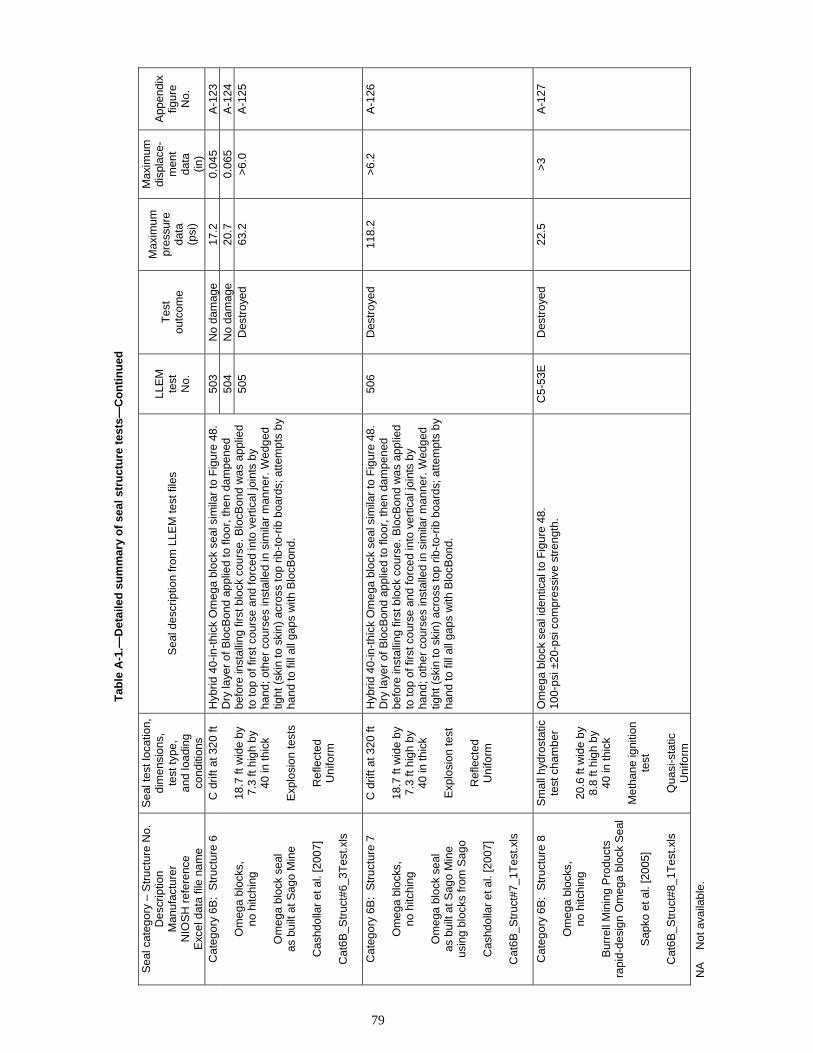
Tab
le A
-1.—
Det
aile
d s
um
mar
y o
f se
al s
tru
ctu
re t
ests
—C
on
tin
ued
Sea
l cat
egor
y –
Str
uctu
re N
o.
Des
crip
tion
Man
ufac
ture
rN
IOS
H r
efer
ence
E
xcel
dat
a fil
e na
me
Sea
l tes
t loc
atio
n,
dim
ensi
ons,
te
st ty
pe,
and
load
ing
cond
ition
s
Sea
l des
crip
tion
from
LLE
M te
st fi
les
LLE
Mte
stN
o.
Tes
tou
tcom
e
Max
imum
pr
essu
reda
ta(p
si)
Max
imum
di
spla
ce-
men
tda
ta(in
)
App
endi
xfig
ure
No.
Cat
egor
y 6B
: S
truc
ture
6
Om
ega
bloc
ks,
no h
itchi
ng
Om
ega
bloc
k se
al
as b
uilt
at S
ago
Min
e
Cas
hdol
lar
et a
l. [2
007]
Cat
6B_S
truc
t#6_
3Tes
t.xls
C d
rift a
t 320
ft
18.7
ft w
ide
by
7.3
ft hi
gh b
y40
in th
ick
Exp
losi
on te
sts
Ref
lect
ed
Uni
form
Hyb
rid 4
0-in
-thi
ck O
meg
a bl
ock
seal
sim
ilar
to F
igur
e 48
. D
ry la
yer
of B
locB
ond
appl
ied
to fl
oor,
then
dam
pene
d be
fore
inst
allin
g fir
st b
lock
cou
rse.
Blo
cBon
d w
as a
pplie
d to
top
of f
irst c
ours
e an
d fo
rced
into
ver
tical
join
ts b
yha
nd; o
ther
cou
rses
inst
alle
d in
sim
ilar
man
ner.
Wed
ged
tight
(sk
in to
ski
n) a
cros
s to
p rib
-to-
rib b
oard
s; a
ttem
pts
by
hand
to fi
ll al
l gap
s w
ith B
locB
ond.
503
No
dam
age
17.2
0.
045
A-1
23
504
No
dam
age
20.7
0.
065
A-1
24
505
Des
troy
ed
63.2
>
6.0
A-1
25
Cat
egor
y 6B
: S
truc
ture
7
Om
ega
bloc
ks,
no h
itchi
ng
Om
ega
bloc
k se
al
as b
uilt
at S
ago
Min
eus
ing
bloc
ks fr
om S
ago
Cas
hdol
lar
et a
l. [2
007]
Cat
6B_S
truc
t#7_
1Tes
t.xls
C d
rift a
t 320
ft
18.7
ft w
ide
by
7.3
ft hi
gh b
y40
in th
ick
Exp
losi
on te
st
Ref
lect
ed
Uni
form
Hyb
rid 4
0-in
-thi
ck O
meg
a bl
ock
seal
sim
ilar
to F
igur
e 48
. D
ry la
yer
of B
locB
ond
appl
ied
to fl
oor,
then
dam
pene
d be
fore
inst
allin
g fir
st b
lock
cou
rse.
Blo
cBon
d w
as a
pplie
d to
top
of f
irst c
ours
e an
d fo
rced
into
ver
tical
join
ts b
yha
nd; o
ther
cou
rses
inst
alle
d in
sim
ilar
man
ner.
Wed
ged
tight
(sk
in to
ski
n) a
cros
s to
p rib
-to-
rib b
oard
s; a
ttem
pts
by
hand
to fi
ll al
l gap
s w
ith B
locB
ond.
506
Des
troy
ed
118.
2 >
6.2
A-1
26
Cat
egor
y 6B
: S
truc
ture
8
Om
ega
bloc
ks,
no h
itchi
ng
Bur
rell
Min
ing
Pro
duct
s ra
pid-
desi
gn O
meg
a bl
ock
Sea
l
Sap
ko e
t al.
[200
5]
Cat
6B_S
truc
t#8_
1Tes
t.xls
Sm
all h
ydro
stat
ic
test
cha
mbe
r
20.6
ft w
ide
by
8.8
ft hi
gh b
y40
in th
ick
Met
hane
igni
tion
test
Qua
si-s
tatic
Uni
form
Om
ega
bloc
k se
al id
entic
al to
Fig
ure
48.
100-
psi ±
20-p
si c
ompr
essi
ve s
tren
gth.
C
5-53
E
Des
troy
ed
22.5
>
3 A
-127
NA
N
ot a
vaila
ble.
79

50 2
45 1.8 Pressure - static, nonuniform loading
Displacement 40 1.6
pre
ssu
re -
psi
dis
pla
cem
ent
- in
ches
35
30
25
20
15
10
5
0
1.4
1.2
1
0.8
0.6
0.4
0.2
0
0.400 0.450 0.500 0.550 0.600 0.650 0.700 0.750 0.800
time - seconds
Figure A-1.—Category 1A - structure #1 - test 1 - static, nonuniform loading. Insteel 3-D seal - shotcrete with reinforcement - LLEM test #419.
450
40
35
30
25
20
15
10
5
0
Pressure - static, nonuniform loading
Displacement
45 3.5
3
2.5
2
1.5
1
0.5
0
dis
pla
cem
en
t -
inch
es
pre
ssu
re -
ps
i
0.400 0.450 0.500 0.550 0.600 0.650 0.700 0.750 0.800
time - seconds
Figure A-2.—Category 1A - structure #2 - test 1 - static, nonuniform loading. Insteel 3-D seal - shotcrete with reinforcement - LLEM test #419.
80

45 3.5
50 4
40
35
30
25
20
15
10
5
0
Pressure - static, nonuniform loading
Displacement 3
2.5
2
1.5
1
0.5
0
pre
ssu
re -
psi
dis
pla
cem
ent
- in
ches
0.400 0.450 0.500 0.550 0.600 0.650 0.700 0.750 0.800
time - seconds
Figure A-3.—Category 1A - structure #3 - test 1 - static, nonuniform loading. Insteel 3-D seal - shotcrete with reinforcement - LLEM test #419.
pre
ssu
re -
psi
dis
pla
cem
ent
- in
ches
60
50
40
30 Pressure - static, nonuniform loading
Displacement - (noise in data)
0.05
0.1
0.09
0.08
0.07
0.06
0.04
20 0.03
0.02 10
0.01
0 0
0.400 0.450 0.500 0.550 0.600 0.650 0.700 0.750 0.800
time - seconds
Figure A-4.—Category 1A - structure #4 - test 1 - static, nonuniform loading. Insteel 3-D seal - shotcrete with reinforcement - LLEM test #420.
81

0
5
10
15
20
25
30
35
40
45
50
pre
ssu
re -
psi
0
0.5
1
1.5
2
2.5
3
3.5
4
dis
pla
cem
en
t -
inch
es
Pressure - static, nonuniform loading
Displacement
0.400 0.450 0.500 0.550 0.600 0.650 0.700 0.750 0.800
time - seconds
Figure A-5.—Category 1A - structure #5 - test 1 - static, nonuniform loading. Insteel 3-D seal - shotcrete with reinforcement - LLEM test #420.
45
50 0.1
40
35
30
25
20
15
10
5
0
Pressure - static, nonuniform loading
Displacement - (noise in data) 0.08
0.07
0.06
0.05
0.04
0.03
0.02
0.01
0
pre
ssu
re -
psi
dis
pla
cem
en
t -
inch
es
0.400 0.450 0.500 0.550 0.600 0.650 0.700 0.750 0.800
time - seconds
Figure A-6— Category 1A - structure #6 - test 1 - static, nonuniform loading. Insteel 3-D seal - shotcrete with reinforcement - LLEM test #420.
0.09
82

pre
ssu
re -
psi
35 0.25
25
30 Pressure - static, uniform loading
Displacement 0.20
20 0.15
15 0.10
5
10
0.05
0
0 100 200 300 400
time - seconds
500 600 700 800
0.00
Figure A-7.—Category 1A - structure #7 - test 1 - static, uniform loading. Insteel 3-D seal - shotcrete with reinforcement - PR-1.
dis
pla
cem
ent
- in
ches
pre
ssu
re -
psi
100
60
70
80
90
Pressure - LLEM#347 - static, nonuniform loading
Pressure - LLEM#348 - static, nonuniform loading
Pressure - LLEM#349 - static, nonuniform loading
Pressure - LLEM#350 - static, nonuniform loading
50
40
30
20
10
0
2.400 2.500 2.600 2.700 2.800 2.900 3.000 3.100 3.200 3.300 3.400
time - seconds
Figure A-8.—Category 1B - structure #1 - tests 1 to 4 - static, nonuniform loading. Meshblock seal - shotcrete with reinforcement - LLEM tests #347–350.
83

50
pre
ssu
re -
psi
45 Pressure - LLEM#351 - static, nonuniform loading
40 Pressure - LLEM#354 - static, nonuniform loading
35 Pressure - LLEM#355 - static, nonuniform loading
30 Pressure - LLEM#358 - static, nonuniform loading
25
20
15
10
5
0
0.400 0.500 0.600 0.700 0.800 0.900 1.000 1.100 1.200 1.300 1.400
time - seconds
Figure A-9.—Category 1B - structure #1 - tests 5 to 8 - static, nonuniform loading. Meshblock seal - shotcrete with reinforcement - LLEM tests #351–358.
pre
ss
ure
- p
si
100
90 Pressure - LLEM#359 - static, nonuniform loading
80 Pressure - LLEM#360 - static, nonuniform loading
70 Pressure - LLEM#361 - static, nonuniform loading
Pressure - LLEM#362 - static, nonuniform loading 60
50
40
30
20
10
0
0.400 0.500 0.600 0.700 0.800 0.900 1.000 1.100 1.200 1.300 1.400
time - seconds
Figure A-10.—Category 1B - structure #1 - tests 9 to 12 - static, nonuniform loading. Meshblock seal - shotcrete with reinforcement - LLEM tests #359–362.
84

0
5
10
15
20
25
30
35
40
45
50
pre
ss
ure
- p
si
Pressure - LLEM#363 - static, nonuniform loading
Pressure - LLEM#364 - static, nonuniform loading
Pressure - LLEM#365 - static, nonuniform loading
Pressure - LLEM#366 - static, nonuniform loading
0.400 0.500 0.600 0.700 0.800 0.900 1.000 1.100 1.200 1.300 1.400
time - seconds
Figure A-11.—Category 1B - structure #1 - tests 13 to 16 - static, nonuniform loading. Meshblock seal - shotcrete with reinforcement - LLEM tests #363–366.
0
10
20
30
40
50
60
70
80
90
100
pre
ssu
re -
psi
Pressure - LLEM#347 - static, nonuniform loading
Pressure - LLEM#348 - static, nonuniform loading
Pressure - LLEM#349 - static, nonuniform loading
2.400 2.500 2.600 2.700 2.800 2.900 3.000 3.100 3.200 3.300 3.400
time - seconds
Figure A-12.—Category 1B - structure #2 - tests 1 to 3 - static, nonuniform loading. Meshblock seal - shotcrete with reinforcement - LLEM tests #347–349.
85

0
1
2
3
4
5
6
7
8
pre
ss
ure
- t
ime
Pressure - LLEM#350 - static, nonuniform loading
Pressure - LLEM#351 - static, nonuniform loading
3.000 3.100 3.200 3.300 3.400 3.500 3.600 3.700 3.800 3.900 4.000
time - seconds
Figure A-13.—Category 1B - structure #2 - tests 4 and 5 - static, nonuniform loading. Meshblock seal - shotcrete with reinforcement - LLEM tests #350–351.
120
pre
ss
ure
- p
si
0
20
40
60
80
100
Pressure - LLEM#347 - static, nonuniform loading
Pressure - LLEM#348 - static, nonuniform loading
Pressure - LLEM#349 - static, nonuniform loading
2.700 2.750 2.800 2.850 2.900 2.950 3.000 3.050 3.100 3.150 3.200
time - seconds
Figure A-14.—Category 1B - structure #3 - tests 1 to 3 - static, nonuniform loading. Meshblock seal - shotcrete with reinforcement - LLEM tests #347–349.
86

0
10
20
30
40
50
60
70
80
90
100
pre
ssu
re -
ps
i Pressure - LLEM#347 - static, nonuniform loading
Pressure - LLEM#348 - static, nonuniform loading
2.700 2.750 2.800 2.850 2.900 2.950 3.000 3.050 3.100 3.150 3.200
time - seconds
Figure A-15.—Category 1B - structure #4 - tests 1 and 2 - static, nonuniform loading. Meshblock seal - shotcrete with reinforcement - LLEM tests #347–348.
pre
ss
ure
- p
si
0
10
20
30
40
50
60
70
80
Pressure - LLEM#347 - static, nonuniform loading
Pressure - LLEM#348 - static, nonuniform loading
2.700 2.750 2.800 2.850 2.900 2.950 3.000 3.050 3.100 3.150 3.200
time - seconds
Figure A-16.—Category 1B - structure #5 - tests 1 and 2. Meshblock seal - shotcrete with reinforcement - LLEM tests #347–348.
87

pre
ssu
re -
ps
i
-1
-2
3.000 3.100 3.200 3.300 3.400 3.500 3.600 3.700 3.800 3.900 4.000
time - seconds
Pressure - LLEM#350 - static, nonuniform loading
Pressure - LLEM#350 - static, nonuniform loading
Figure A-17.—Category 1B - structure #6 - tests 1 and 2 - static, nonuniform loading. Meshblock seal - shotcrete with reinforcement - LLEM tests #350–351.
6
5
4
3
2
1
0
0
10
20
30
40
50
60
70
80
90
100
pre
ssu
re -
psi
0
0.1
0.2
0.3
0.4
0.5
0.6
0.7
0.8
0.9
1
dis
pla
cem
ent
- in
ch
es
Pressure - reflected, uniform loading
Displacement
0.400 0.450 0.500 0.550 0.600 0.650 0.700 0.750 0.800
time - seconds
Figure A-18.—Category 2A - structure #1 - test 1 - reflected, uniform loading. Pumpable 48 in - LLEM test #508.
88

0
50
100
150
200
250
pre
ssu
re -
psi
0
1
2
3
4
5
6
dis
pla
cem
ent
- in
ches
Pressure - reflected, uniform loading
Displacement
0.400 0.450 0.500 0.550 0.600 0.650 0.700 0.750 0.800
time - seconds
Figure A-19.—Category 2A - structure #1 - test 2 - reflected, uniform loading. Pumpable 48 in - LLEM test #509.
0
5
10
15
20
25
30
35
pre
ssu
re -
psi
0
0.5
1
1.5
2
2.5
3
3.5
4
dis
pla
cem
ent
- in
ches
Pressure - static, uniform loading
Displacement
0 5 10 15 20 25
time - seconds
Figure A-20.—Category 2A - structure #2 - test 1 - static, uniform loading. Pumpable 48 in - test C3-44E.
89

20 0.4
25
Pressure - static, uniform loading
Displacement
0.5
0.45
dis
pla
cem
en
t -
inc
he
s
pre
ssu
re -
psi
15
10
5
0
0.35
0.3
0.25
0.2
0.15
0.1
0.05
0
0 200 400 600 800 1000 1200
time - seconds
Figure A-21.—Category 2A - structure #3 - test 1 - static, uniform loading. Pumpable 48 in - test C7-64W.
35
pre
ssu
re -
psi
1.2
30
25
20
15
10
5
0
Pressure - static, uniform loading
Displacement 1
0.8
0.6
0.4
0.2
0
dis
pla
cem
en
t -
inc
he
s
0 200 400 600 800 1000 1200
time - seconds
Figure A-22.—Category 2A - structure #3 - test 2 - static, uniform loading. Pumpable 48 in - test C7-68W.
90

10
pre
ssu
re -
psi
dis
pla
cem
ent
- in
che
s
30
25
20
15
0
0.1
0.2
0.3
0.4
0.5
0.6
0.7
0.8
Pressure - static, uniform loading
Displacement
0 200 400 600 800 1000 1200
time - seconds
5
0
Figure A-23.—Category 2A - structure #3 - test 3 - static, uniform loading. Pumpable 48 in - test C7-70W.
0
5
10
15
20
25
30
pre
ssu
re -
psi
0
0.5
1
1.5
2
2.5
3
3.5
4
dis
pla
cem
en
t -
inch
es
Pressure - static, uniform loading
Displacement
0 0.5 1 1.5 2 2.5
time - seconds
Figure A-24.—Category 2A - structure # 4 - test 1 - static, uniform loading. Pumpable 48 in - test L2-51E.
91

pre
ssu
re -
psi
40
35
30
25
20
15
10
5
0
Pressure - LLEM#354 - static, nonuniform loading
Pressure - LLEM#355 - static, nonuniform loading
0.400 0.450 0.500 0.550 0.600 0.650 0.700 0.750 0.800 0.850 0.900
time - seconds
Figure A-25.—Category 2B - structure #1 - tests 1 and 2 - static, nonuniform loading. Pumpable 36 in - LLEM tests #354–355.
pre
ssu
re -
psi
50
45
40
35
30
25
20
15
10
5
0
Pressure - LLEM#354 - static, nonuniform loading
Pressure - LLEM#355 - static, nonuniform loading
0.400 0.450 0.500 0.550 0.600 0.650 0.700 0.750 0.800 0.850 0.900
time - seconds
Figure A-26.—Category 2C - structure #1 - tests 1 and 2 - static, nonuniform loading. Pumpable 24 in - LLEM tests #354–355.
92

pre
ssu
re -
psi
40
35
30
25
20
15
10
5
0
Pressure - LLEM#354 - static, nonuniform loading
Pressure - LLEM#355 - static, nonuniform loading
0.400 0.450 0.500 0.550 0.600 0.650 0.700 0.750 0.800 0.850 0.900
time - seconds
Figure A-27.—Category 2C - structure #2 - tests 1 and 2 - static, nonuniform loading. Pumpable 24 in - LLEM tests #354–355.
pre
ssu
re -
psi
40
35
30
25
20
15
10
5
0
Pressure - LLEM#354 - static, nonuniform loading
Pressure - LLEM#355 - static, nonuniform loading
0.400 0.500 0.600 0.700 0.800 0.900 1.000 1.100 1.200 1.300 1.400
time - seconds
Figure A-28.—Category 2C - structure #3 - tests 1 and 2 - static, nonuniform loading. Pumpable 24 in - LLEM tests #354–355.
93

40 4
35 3.5
30
25
20
15
10
5
0
Pressure - static, nonuniform loading
Displacement
pre
ssu
re -
psi
dis
pla
cem
ent
- in
ches
3
2.5
2
1.5
1
0.5
0
0.450 0.500 0.550 0.600 0.650 0.700 0.750
time - seconds
Figure A-29.—Category 2C - structure #4 - test 1 - static, nonuniform loading. Pumpable 24 in - LLEM test #403.
pre
ssu
re -
psi
dis
pla
cem
en
t -
inch
es
40 4
35
30
25
20
15
10
5
0
Pressure - static, nonuniform loading Displacement 3.5
3
2.5
2
1.5
1
0.5
0
0.450 0.500 0.550 0.600 0.650 0.700 0.750
time - seconds
Figure A-30.—Category 2C - structure #4 - test 2 - static, nonuniform loading. Pumpable 24 in - LLEM test #404.
94

35 3.5
40 4
pre
ssu
re -
psi
dis
pla
cem
en
t -
inch
es
30
25
20
15
10
5
0
Pressure - static, nonuniform loading
Displacement
3
2.5
2
1.5
1
0.5
0
0.450 0.500 0.550 0.600 0.650 0.700 0.750
time - seconds
Figure A-31.—Category 2C - structure #4 - test 3 - static, nonuniform loading. Pumpable 24 in - LLEM test #405.
pre
ssu
re -
psi
dis
pla
cem
ent
- in
ches
40 4
35 3.5
30
25
20
15
10
5
0
Pressure - static, nonuniform loading
Displacement
3
2.5
2
1.5
1
0.5
0
0.450 0.500 0.550 0.600 0.650 0.700 0.750
time - seconds
Figure A-32.—Category 2C - structure #4 - test 4 - static, nonuniform loading. Pumpable 24 in - LLEM test #406.
95

35 0.18
40 0.2
30
25
20
15
10
5
0
Pressure - static, nonuniform loading
Displacement - (noise in data) 0.16
0.14
0.12
0.1
0.08
0.06
0.04
0.02
0
pre
ssu
re -
psi
dis
pla
cem
ent
- in
ches
0.350 0.450 0.550 0.650 0.750 0.850 0.950
time - seconds
Figure A-33.—Category 3A - structure #1 - test 1 - static, nonuniform loading. Standard solid-concrete-block seal - LLEM test #403.
35
40
pre
ssu
re -
psi
dis
pla
cem
en
t -
inch
es
0.2
Pressure - static, nonuniform loading
Displacement - (noise in data)
0.18
30
25
20
15
10
5
0
0.16
0.14
0.12
0.1
0.08
0.06
0.04
0.02
0
0.350 0.450 0.550 0.650 0.750 0.850 0.950
time - seconds
Figure A-34.—Category 3A - structure #1 - test 2 - static, nonuniform loading. Standard solid-concrete-block seal - LLEM test #404.
96

0
5
10
15
20
25
30
35
40
pre
ssu
re -
psi
0
0.02
0.04
0.06
0.08
0.1
0.12
0.14
0.16
0.18
0.2
dis
pla
cem
ent
- in
ches
Pressure - static, nonuniform loading
Displacement - (noise in data)
0.350 0.450 0.550 0.650 0.750 0.850 0.950
time - seconds
Figure A-35.—Category 3A - structure #1 - test 3 - static, nonuniform loading. Standard solid-concrete-block seal - LLEM test #405.
0
5
10
15
20
25
30
35
40
pre
ssu
re -
psi
0
0.02
0.04
0.06
0.08
0.1
0.12
0.14
0.16
0.18
0.2
dis
pla
cem
en
t -
inch
es
Pressure - static, nonuniform loading
Displacement - (noise in data)
0.350 0.450 0.550 0.650 0.750 0.850 0.950
time - seconds
Figure A-36.—Category 3A - structure #1 - test 4 - static, nonuniform loading. Standard solid-concrete-block seal - LLEM test #406.
97

-10
-5
0
5
10
15
20
25
30
0.300 0.500 0.700 0.900 1.100 1.300 1.500 1.700 1.900 2.100 2.300
pre
ssu
re -
ps
i Pressure - LLEM#500 - static, nonuniform loading
Pressure - LLEM#501 - static, nonuniform loading
Pressure - LLEM#502 - static, nonuniform loading
Pressure - LLEM#503 - static, nonuniform loading
Pressure - LLEM#504 - static, nonuniform loading
Pressure - LLEM#505 - static, nonuniform loading
time - seconds
Figure A-37.—Category 3A - structure #2 - tests 1 to 6 - static, nonuniform loading. Standard solid-concrete-block seal - LLEM tests #500–505.
-30
-20
-10
0
10
20
30
40
50
0.300 0.400 0.500 0.600 0.700 0.800 0.900 1.000 1.100 1.200 1.300
pre
ssu
re -
psi
Pressure - LLEM#506 - static, nonuniform loading
Pressure - LLEM#507 - static, nonuniform loading
Pressure - LLEM#508 - static, nonuniform loading
Pressure - LLEM#509 - static, nonuniform loading
time - seconds
Figure A-38.—Category 3A - structure #2 - tests 7 to 10 - static, nonuniform loading. Standard solid-concrete-block seal - LLEM tests #506–509.
98

80 0.45
90 0.5
70
60
50
40
30
20
10
0
0.500 0.550 0.600 0.650 0.700 0.750 0.800 0.850 0.900 0.950 1.000
time - seconds
Pressure - static, nonuniform loading
Displacement - (noise in data) 0.4
0.35
0.3
0.25
0.2
0.15
0.1
0.05
pre
ssu
re -
ps
i
dis
pla
cem
en
t -
inch
es
-10 0
Figure A-39.—Category 3A - structure #3 - test 1 - static, nonuniform loading. Standard solid-concrete-block seal - LLEM test #506.
35
pre
ssu
re -
psi
dis
pla
cem
ent
- in
ches
40 0.2
0.18 Pressure - static, nonuniform loading
Displacement - (noise in data) 30
25
20
15
10
5
0
0.16
0.14
0.12
0.1
0.08
0.06
0.04
0.02
0
0.500 0.550 0.600 0.650 0.700 0.750 0.800 0.850 0.900 0.950 1.000
time - seconds
Figure A-40.—Category 3A - structure #3 - test 2 - static, nonuniform loading. Standard solid-concrete-block seal - LLEM test #507.
99

0
10
20
30
40
50
60
pre
ssu
re -
psi
0
0.02
0.04
0.06
0.08
0.1
0.12
0.14
0.16
dis
pla
cem
ent
- in
ches
Pressure - static, uniform loading
Displacement
0 5 10 15 20 25
time - seconds
Figure A-41.—Category 3A - structure #4 - test 1 - static, uniform loading. Standard solid-concrete-block seal - test C1-5E.
0
10
20
30
40
50
60
70
80
90
100
pre
ssu
re -
psi
Pressure - static, uniform loading
0 5 10 15 20 25
time - seconds
Figure A-42.—Category 3A - structure #4 - test 2 - static, uniform loading. Standard solid-concrete-block seal - test C1-8E.
100

100 0.25
90
80
70
60
50
40
30
20
10
0
Pressure - static, uniform loading
Displacement - (noise in data)
pre
ssu
re -
psi
dis
pla
cem
en
t -
inch
es
0.2
0.15
0.1
0.05
0
0 5 10 15 20 25
time - seconds
Figure A-43.—Category 3A - structure #4 - test 3 - static, uniform loading. Standard solid-concrete-block seal - test C1-9E.
pre
ssu
re -
ps
i
dis
pla
cem
ent
- in
ch
es
100 0.25
90
80
70
60
50
40
30
20
10
0
Pressure - static, uniform loading
Displacement
0.2
0.15
0.1
0.05
0
0 5 10 15 20 25
time - seconds
Figure A-44.—Category 3A - structure #4 - test 4 - static, uniform loading. Standard solid-concrete-block seal - test C1-10E.
101
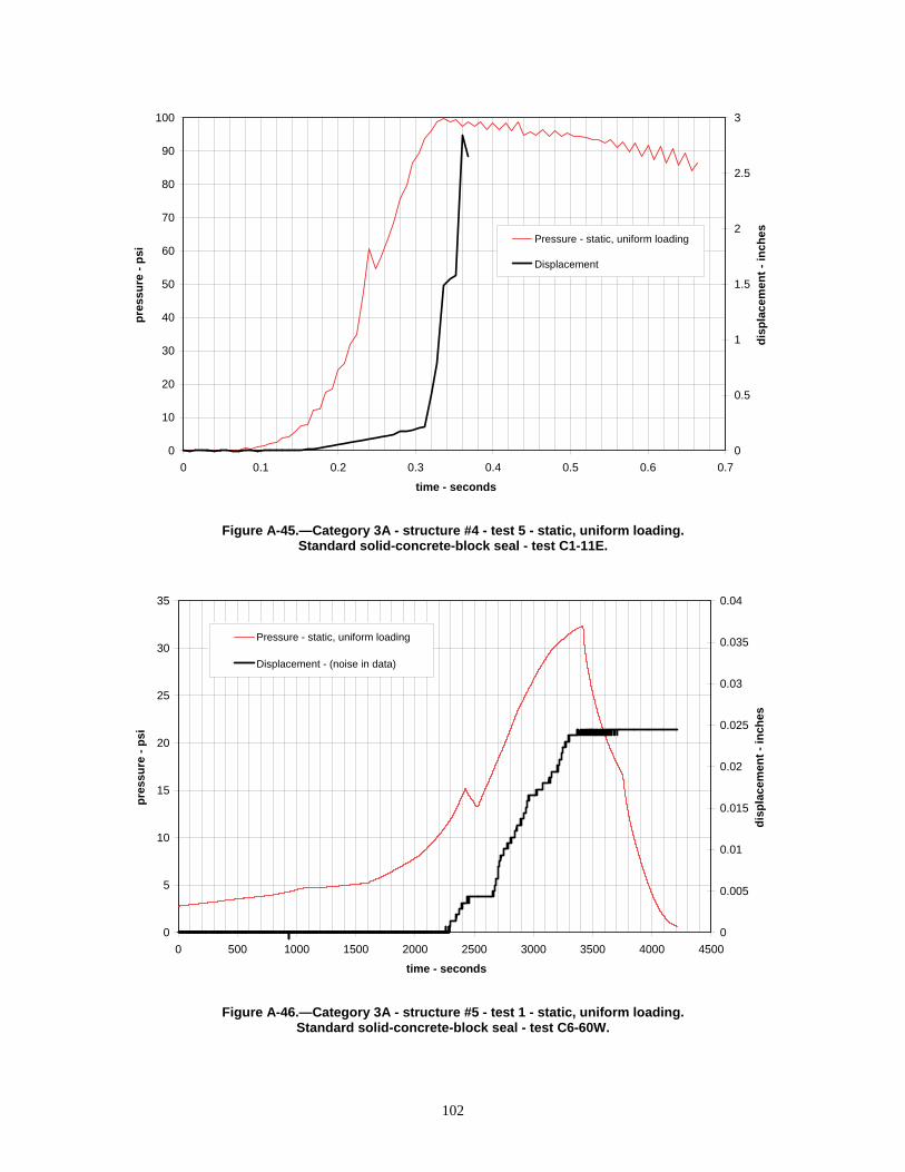
100
Pressure - static, uniform loading
Displacement
3
90
2.5 80
70 2
pre
ssu
re -
psi
dis
pla
cem
ent
- in
che
s
60
50
40
30
20
10
0
1.5
1
0.5
0
0 0.1 0.2 0.3 0.4 0.5 0.6 0.7
time - seconds
Figure A-45.—Category 3A - structure #4 - test 5 - static, uniform loading. Standard solid-concrete-block seal - test C1-11E.
35
pre
ssu
re -
psi
dis
pla
cem
ent
- in
ches
0.04
30
25
20
15
10
5
0
Pressure - static, uniform loading
Displacement - (noise in data)
0.035
0.03
0.025
0.02
0.015
0.01
0.005
0
0 500 1000 1500 2000 2500 3000 3500 4000 4500
time - seconds
Figure A-46.—Category 3A - structure #5 - test 1 - static, uniform loading. Standard solid-concrete-block seal - test C6-60W.
102

6 8 10 12
- seconds
ture #5 - test 2 - static, uniform loading. ete-block seal - test C6-62E.
103
90 0.35
100 0.4
Pressure - static, uniform loading
Displacement - (noise in data)
pre
ssu
re -
psi
dis
pla
cem
ent
- in
ches
80
70
60
50
40
30
20
10
0
0.3
0.25
0.2
0.15
0.1
0.05
0
0 2 4
time
Figure A-47.—Category 3A - strucStandard solid-concr
0
0.5
1
1.5
2
2.5
3
3.5
4
dis
pla
cem
ent
- in
ches
Pressure - static, uniform loading
Displacement
15 20 25 30
- seconds
ture #6 - test 1 - static, uniform loading. ete-block seal - test L1-37E.
0
5
10
15
20
25
30
35
pre
ssu
re -
psi
0 5 10
time
Figure A-48.—Category 3A - strucStandard solid-concr

0
5
10
15
20
25
pre
ssu
re -
psi
0
0.02
0.04
0.06
0.08
0.1
0.12
0.14
0.16
0.18
0.2
dis
pla
cem
en
t -
inch
es
Pressure - static, uniform loading
Displacement
0 50 100 150 200 250 300
time - seconds
Figure A-49.—Category 3A - structure #7 - test 1 - static, uniform loading. Standard solid-concrete-block seal - test SRCM 1.
pre
ssu
re -
psi
0
5
10
15
20
25
30
35
40
Pressure - static, nonuniform loading
Pressure - static, nonuniform loading
Pressure - static, nonuniform loading
0.400 0.450 0.500 0.550 0.600 0.650 0.700 0.750 0.800 0.850 0.900
time - seconds
Figure A-50.—Category 3B - structure #1 - test 1 - static, nonuniform loading. Solid-concrete-block seal with Packsetter bags - LLEM test #365.
104

0
5
10
15
20
25
30
35
40
45
50
pre
ssu
re -
psi
Pressure - LLEM#365 - static, nonuniform loading
Pressure - LLEM#366 - static, nonuniform loading
0.400 0.450 0.500 0.550 0.600 0.650 0.700 0.750 0.800 0.850 0.900
time - seconds
Figure A-51.—Category 3B - structure #2 - tests 1 and 2 - static, nonuniform loading. Solid-concrete-block seal with Packsetter bags - LLEM tests #365–366.
0
5
10
15
20
25
30
35
40
45
50
pre
ssu
re -
ps
i
Pressure - LLEM#365 - static, nonuniform loading
Pressure - LLEM#366 - static, nonuniform loading
0.400 0.450 0.500 0.550 0.600 0.650 0.700 0.750 0.800 0.850 0.900
time - seconds
Figure A-52.—Category 3B - structure #3 - tests 1 and 2 - static, nonuniform loading. Solid-concrete-block seal with Packsetter bags - LLEM tests #365–366.
105

1 0.05
0.9 Pressure - static, nonuniform loading - (noise in data) 0.045
0.8 Displacement - (noise in data) 0.04
0.7 0.035
0.6 0.03
0.5 0.025
0.4 0.02
0.3 0.015
0.2 0.01
0.1 0.005
0 0
0.000 0.500 1.000 1.500 2.000 2.500
time - seconds
pre
ssu
re -
psi
dis
pla
cem
ent
- in
ches
Figure A-53.—Category 3C - structure #1 - test 1 - static, nonuniform loading. Hollow-core concrete-block ventilation stopping - LLEM test #427.
pre
ssu
re -
psi
dis
pla
cem
ent
- in
ches
5 5
4.5 4.5
4 4
3.5 3.5
3 3
2.5 2.5
2 2Pressure - static, nonuniform loading - (noise in data)
1.5 1.5 Displacement
1 1
0.5 0.5
0 0
0.000 0.500 1.000 1.500 2.000 2.500
time - seconds
Figure A-54.—Category 3C - structure #1 - test 2 - static, nonuniform loading.
Hollow-core concrete-block ventilation stopping - LLEM test #428.
106

pre
ssu
re -
psi
dis
pla
cem
ent
- in
ches
1 0.05
0.9 Pressure - static, nonuniform loading - (noise in data) 0.045
0.8 Displacement - (noise in data) 0.04
0.7 0.035
0.6 0.03
0.5 0.025
0.4 0.02
0.3 0.015
0.2 0.01
0.1 0.005
0 0
0.000 0.500 1.000 1.500 2.000 2.500
time - seconds
Figure A-55.—Category 3C - structure #2 - test 1 - static, nonuniform loading. Hollow-core concrete-block ventilation stopping - LLEM test #427.
pre
ssu
re -
psi
dis
pla
cem
ent
- in
ches
5 5
4.5 4.5
4 4
3.5 3.5
3 3
2.5 2.5Pressure - static, nonuniform loading - (noise in data)
2 2Displacement
1.5 1.5
1 1
0.5 0.5
0 0
0.000 0.500 1.000 1.500 2.000 2.500
time - seconds
Figure A-56.—Category 3C - structure #2 - test 2 - static, nonuniform loading. Hollow-core concrete-block ventilation stopping - LLEM test #428.
107

pre
ssu
re -
psi
dis
pla
cem
en
t -
inch
es
5 0.5
4.5 Pressure - static, nonuniform loading - (noise in data) 0.45
4 Displacement - (noise in data) 0.4
3.5 0.35
3 0.3
2.5 0.25
2 0.2
1.5 0.15
1 0.1
0.5 0.05
0 0
0.500 0.600 0.700 0.800 0.900 1.000 1.100 1.200 1.300 1.400 1.500
time - seconds
Figure A-57.—Category 3C - structure #3 - test 1 - static, nonuniform loading. Hollow-core concrete-block ventilation stopping - LLEM test #427.
pre
ssu
re -
psi
dis
pla
cem
ent
- in
ches
5 0.1
Pressure - static, nonuniform loading - (noise in data) 4.5 0.09
Displacement - (noise in data) 4 0.08
3.5 0.07
3 0.06
2.5 0.05
2 0.04
1.5 0.03
1 0.02
0.5 0.01
0 0
0.500 0.600 0.700 0.800 0.900 1.000 1.100 1.200 1.300 1.400 1.500
time - seconds
Figure A-58.—Category 3C - structure #3 - test 2 - static, nonuniform loading. Hollow-core concrete-block ventilation stopping - LLEM test #428.
108
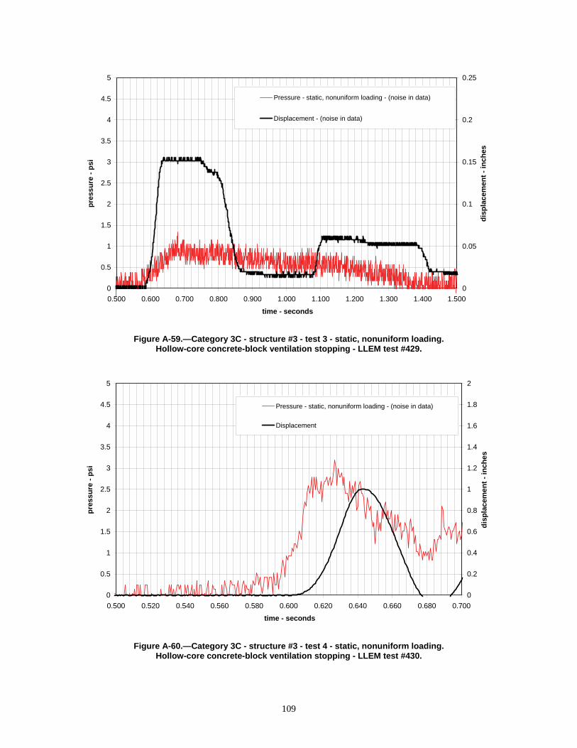
4.5
5 0.25
4
3.5
3
2.5
2
1.5
1
0.5
0
Pressure - static, nonuniform loading - (noise in data)
Displacement - (noise in data) 0.2
0.15
0.1
0.05
0
pre
ssu
re -
psi
dis
pla
cem
ent
- in
ches
0.500 0.600 0.700 0.800 0.900 1.000 1.100 1.200 1.300 1.400 1.500
time - seconds
Figure A-59.—Category 3C - structure #3 - test 3 - static, nonuniform loading. Hollow-core concrete-block ventilation stopping - LLEM test #429.
4.5
pre
ssu
re -
psi
dis
pla
cem
ent
- in
ches
5 2
Pressure - static, nonuniform loading - (noise in data)
Displacement 4
3.5
3
2.5
2
1.5
1
0.5
0
1.6
1.4
1.2
1
0.8
0.6
0.4
0.2
0
0.500 0.520 0.540 0.560 0.580 0.600 0.620 0.640 0.660 0.680 0.700
time - seconds
Figure A-60.—Category 3C - structure #3 - test 4 - static, nonuniform loading. Hollow-core concrete-block ventilation stopping - LLEM test #430.
1.8
109

4.5 1.8
5 2
4
3.5
3
2.5
2
1.5
1
0.5
0
Pressure - static, nonuniform loading - (noise in data)
Displacement 1.6
1.4
1.2
1
0.8
0.6
0.4
0.2
0
pre
ssu
re -
psi
dis
pla
cem
ent
- in
ches
0.500 0.520 0.540 0.560 0.580 0.600 0.620 0.640 0.660 0.680 0.700
time - seconds
Figure A-61.—Category 3C - structure #3 - test 5 - static, nonuniform loading. Hollow-core concrete-block ventilation stopping - LLEM test #432.
4.5
pre
ssu
re -
psi
dis
pla
cem
ent
- in
ches
5 5
Pressure - static, nonuniform loading - (noise in data)
Displacement 4
3.5
3
2.5
2
1.5
1
0.5
0
4
3.5
3
2.5
2
1.5
1
0.5
0
0.500 0.520 0.540 0.560 0.580 0.600 0.620 0.640 0.660 0.680 0.700
time - seconds
Figure A-62.—Category 3C - structure #3 - test 6 - static, nonuniform loading. Hollow-core concrete-block ventilation stopping - LLEM test #433.
4.5
110
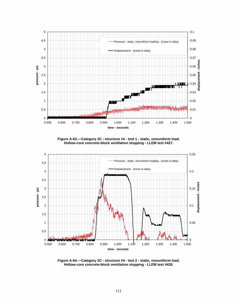
4.5 0.09
5 0.1
4
3.5
3
2.5
2
1.5
1
0.5
0
Pressure - static, nonuniform loading - (noise in data)
Displacement - (noise in data) 0.08
0.07
0.06
0.05
0.04
0.03
0.02
0.01
0
pre
ssu
re -
psi
dis
pla
cem
en
t -
inch
es
0.500 0.600 0.700 0.800 0.900 1.000 1.100 1.200 1.300 1.400 1.500
time - seconds
Figure A-63.—Category 3C - structure #4 - test 1 - static, nonuniform load. Hollow-core concrete-block ventilation stopping - LLEM test #427.
4.5
5
pre
ssu
re -
psi
dis
pla
cem
ent
- in
ches
0.25
4
3.5
3
2.5
2
1.5
1
0.5
0
Pressure - static, nonuniform loading - (noise in data)
Displacement - (noise in data) 0.2
0.15
0.1
0.05
0
0.500 0.600 0.700 0.800 0.900 1.000 1.100 1.200 1.300 1.400 1.500
time - seconds
Figure A-64.—Category 3C - structure #4 - test 2 - static, nonuniform load. Hollow-core concrete-block ventilation stopping - LLEM test #428.
111

4.5
5 0.25
4
3.5
3
2.5
2
1.5
1
0.5
0
Pressure - static, nonuniform loading - (noise in data)
Displacement - (noise in data) 0.2
0.15
0.1
0.05
0
pre
ssu
re -
psi
dis
pla
cem
ent
- in
ches
0.500 0.600 0.700 0.800 0.900 1.000 1.100 1.200 1.300 1.400 1.500
time - seconds
Figure A-65.—Category 3C - structure #4 - test 3 - static, nonuniform load. Hollow-core concrete-block ventilation stopping - LLEM test #429.
4.5
pre
ssu
re -
psi
dis
pla
cem
ent
- in
ches
5 0.5
Pressure - static, nonuniform loading - (noise in data)
Displacement 4
3.5
3
2.5
2
1.5
1
0.5
0
0.4
0.35
0.3
0.25
0.2
0.15
0.1
0.05
0
0.600 0.650 0.700 0.750 0.800
time - seconds
Figure A-66.—Category 3C - structure #4 - test 4 - static, nonuniform load. Hollow-core concrete-block ventilation stopping - LLEM test #430.
0.45
112
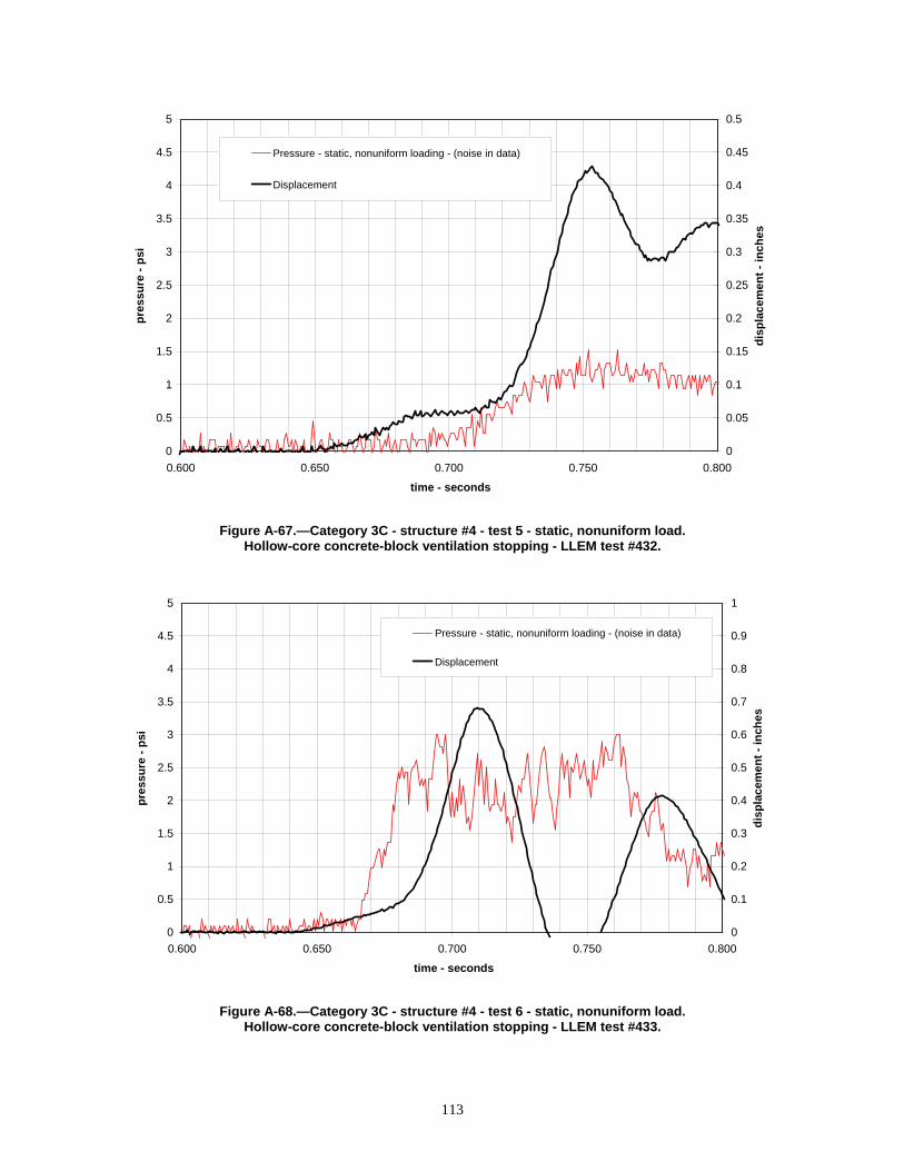
0
0.5
1
1.5
2
2.5
3
3.5
4
4.5
5
pre
ssu
re -
psi
0
0.05
0.1
0.15
0.2
0.25
0.3
0.35
0.4
0.45
0.5
dis
pla
cem
ent
- in
ches
Pressure - static, nonuniform loading - (noise in data)
Displacement
0.600 0.650 0.700 0.750 0.800
time - seconds
Figure A-67.—Category 3C - structure #4 - test 5 - static, nonuniform load. Hollow-core concrete-block ventilation stopping - LLEM test #432.
0
0.5
1
1.5
2
2.5
3
3.5
4
4.5
5
pre
ssu
re -
psi
0
0.1
0.2
0.3
0.4
0.5
0.6
0.7
0.8
0.9
1
dis
pla
cem
en
t -
inch
es
Pressure - static, nonuniform loading - (noise in data)
Displacement
0.600 0.650 0.700 0.750 0.800
time - seconds
Figure A-68.—Category 3C - structure #4 - test 6 - static, nonuniform load. Hollow-core concrete-block ventilation stopping - LLEM test #433.
113

pre
ssu
re -
psi
dis
pla
cem
ent
- in
che
s
5 1
Pressure - static, nonuniform loading - (noise in data) 4.5 0.9
Displacement 4 0.8
3.5 0.7
3 0.6
2.5 0.5
2 0.4
1.5 0.3
1 0.2
0.5 0.1
0 0
0.600 0.650 0.700 0.750 0.800
time - seconds
Figure A-69.—Category 3C - structure #4 - test 7 - static, nonuniform load. Hollow-core concrete-block ventilation stopping - LLEM test #434.
pre
ssu
re -
psi
dis
pla
cem
ent
- in
ches
5 0.1
4.5 Pressure - static, nonuniform loading - (noise in data) 0.09
4 Displacement - (noise in data) 0.08
3.5 0.07
3 0.06
2.5 0.05
2 0.04
1.5 0.03
1 0.02
0.5 0.01
0 0
0.000 0.200 0.400 0.600 0.800 1.000 1.200 1.400
time - seconds
Figure A-70.—Category 3C - structure #5 - test 1 - static, nonuniform loading. Solid-concrete-block ventilation stopping - LLEM test #457.
114

4.5 0.09
5 0.1
4
3.5
3
2.5
2
1.5
1
0.5
0
Pressure - static, nonuniform loading - (noise in data)
Displacement - (noise in data) 0.08
0.07
0.06
0.05
0.04
0.03
0.02
0.01
0
pre
ssu
re -
psi
dis
pla
cem
ent
- in
ches
0.000 0.200 0.400 0.600 0.800 1.000 1.200 1.400
time - seconds
Figure A-71.—Category 3C - structure #5 - test 2 - static, nonuniform loading. Solid-concrete-block ventilation stopping - LLEM test #458.
4.5
pre
ssu
re -
psi
dis
pla
cem
ent
- in
ches
5 1
Pressure - static, nonuniform loading - (noise in data)
Displacement 4
3.5
3
2.5
2
1.5
1
0.5
0
0.8
0.7
0.6
0.5
0.4
0.3
0.2
0.1
0
0.000 0.200 0.400 0.600 0.800 1.000 1.200 1.400
time - seconds
Figure A-72.—Category 3C - structure #5 - test 3 - static, nonuniform loading. Solid-concrete-block ventilation stopping - LLEM test #459.
0.9
115

7 1.75
8 2
pre
ssu
re -
psi
dis
pla
cem
ent
- in
ch
es
6
5
4
3
2
1
0
Pressure - static, nonuniform loading - (noise in data)
Displacement
1.5
1.25
1
0.75
0.5
0.25
0
0.000 0.200 0.400 0.600 0.800 1.000 1.200 1.400
time - seconds
Figure A-73.—Category 3C - structure #5 - test 4 - static, nonuniform loading. Solid-concrete-block ventilation stopping - LLEM test #460.
9
pre
ssu
re -
psi
dis
pla
cem
ent
- in
ches
10 1
Pressure - static, nonuniform loading - (noise in data)
Displacement 8
7
6
5
4
3
2
1
0
0.8
0.7
0.6
0.5
0.4
0.3
0.2
0.1
0
0.000 0.200 0.400 0.600 0.800 1.000 1.200 1.400
time - seconds
Figure A-74.—Category 3C - structure #5 - test 5 - static, nonuniform loading. Solid-concrete-block ventilation stopping - LLEM test #461.
0.9
116

pre
ssu
re -
psi
dis
pla
cem
en
t -
inch
es
10 5
9 Pressure - static, nonuniform loading - (noise in data) 4.5
8 Displacement 4
7 3.5
6 3
5 2.5
4 2
3 1.5
2 1
1 0.5
0 0
0.000 0.200 0.400 0.600 0.800 1.000 1.200 1.400
time - seconds
Figure A-75.—Category 3C - structure #5 - test 6 - static, nonuniform loading. Solid-concrete-block ventilation stopping - LLEM test #462.
pre
ssu
re -
psi
dis
pla
cem
ent
- in
ches
5 0.1
4.5 Pressure - static, nonuniform loading - (noise in data) 0.09
4 Displacement - (noise in data) 0.08
3.5 0.07
3 0.06
2.5 0.05
2 0.04
1.5 0.03
1 0.02
0.5 0.01
0 0
0.000 0.200 0.400 0.600 0.800 1.000 1.200 1.400
time - seconds
Figure A-76.—Category 3C - structure #6 - test 1 - static, nonuniform loading. Solid-concrete-block ventilation stopping - LLEM test #457.
117

5 0.1
4.5 0.09
4
3.5
3
2.5
2
1.5
1
0.5
0
Pressure - static, nonuniform loading - (noise in data)
Displacement - (noise in data) 0.08
0.07
0.06
0.05
0.04
0.03
0.02
0.01
0
pre
ssu
re -
psi
dis
pla
cem
ent
- in
ch
es
0.000 0.200 0.400 0.600 0.800 1.000 1.200 1.400
time - seconds
Figure A-77.—Category 3C - structure #6 - test 2 - static, nonuniform loading. Solid-concrete-block ventilation stopping - LLEM test #458.
pre
ssu
re -
psi
dis
pla
cem
ent
- in
ches
5 0.5
4.5 0.45
4
3.5
3
2.5
2
1.5
1
0.5
0
Pressure - static, nonuniform loading - (noise in data)
Displacement - (noise in data)
0.4
0.35
0.3
0.25
0.2
0.15
0.1
0.05
0
0.000 0.200 0.400 0.600 0.800 1.000 1.200 1.400
time - seconds
Figure A-78.—Category 3C - structure #6 - test 3 - static, nonuniform loading. Solid-concrete-block ventilation stopping - LLEM test #459.
118

9 0.9
10 1
8
7
6
5
4
3
2
1
0
Pressure - static, nonuniform loading - (noise in data)
Displacement
0.8
0.7
0.6
0.5
0.4
0.3
0.2
0.1
0
pre
ssu
re -
psi
dis
pla
cem
en
t -
inc
he
s
0.000 0.200 0.400 0.600 0.800 1.000 1.200 1.400
time - seconds
Figure A-79.—Category 3C - structure #6 - test 4 - static, nonuniform loading. Solid-concrete-block ventilation stopping - LLEM test #460.
8
pre
ssu
re -
ps
i
dis
pla
cem
en
t -
inc
he
s
10 1
9 0.9
Pressure - static, nonuniform loading - (noise in data)
Displacement 7
6
5
4
3
2
1
0
0.7
0.6
0.5
0.4
0.3
0.2
0.1
0
0.000 0.200 0.400 0.600 0.800 1.000 1.200 1.400
time - seconds
Figure A-80.—Category 3C - structure #6 - test 5 - static, nonuniform loading. Solid-concrete-block ventilation stopping - LLEM test #461.
0.8
119

9 0.9
10 1
8
7
6
5
4
3
2
1
0
Pressure - static, nonuniform loading - (noise in data)
Displacement 0.8
0.7
0.6
0.5
0.4
0.3
0.2
0.1
0
pre
ssu
re -
psi
dis
pla
cem
ent
- in
ches
0.000 0.200 0.400 0.600 0.800 1.000 1.200 1.400
time - seconds
Figure A-81.—Category 3C - structure #6 - test 6 - static, nonuniform loading. Solid-concrete-block ventilation stopping - LLEM test #462.
8 pre
ssu
re -
psi
dis
pla
cem
ent
- in
ches
20
18
16
14
12
6
Pressure - static, nonuniform loading -(noise in data)
Displacement
1.2
4 0.8
2 0.4
0 0
4
3.6
3.2
2.8
2.4
10
1.6
0.000 0.200 0.400 0.600 0.800 1.000 1.200 1.400
time - seconds
Figure A-82.—Category 3C - structure #6 - test 7 - static, nonuniform loading. Solid-concrete-block ventilation stopping - LLEM test #463.
2
120

0
2
4
6
8
10
12
14
16
18
20
pre
ssu
re -
psi
Pressure - LLEM#510 - static, nonuniform loading
Pressure - LLEM#511 - static, nonuniform loading
Pressure - LLEM#512 - static, nonuniform loading
1.000 1.050 1.100 1.150 1.200 1.250 1.300 1.350 1.400 1.450 1.500
time - seconds
Figure A-83.—Category 3C - structure #7 - tests 1 to 3 - static, nonuniform loading. Solid-concrete-block ventilation stopping - LLEM tests #510–512.
0
2
4
6
8
10
12
14
16
18
20
pre
ssu
re -
ps
i
Pressure - LLEM#513 - static, nonuniform loading
Pressure - LLEM#514 - static, nonuniform loading
Pressure - LLEM#515 - static, nonuniform loading
1.000 1.050 1.100 1.150 1.200 1.250 1.300 1.350 1.400 1.450 1.500
time - seconds
Figure A-84.—Category 3C - structure #7 - tests 4 to 6 - static, nonuniform loading. Solid-concrete-block ventilation stopping - LLEM tests #513–515.
121

0
5
10
15
20
25
30
35
40
45
50
pre
ssu
re -
psi
Pressure - LLEM#516 - static, nonuniform loading
Pressure - LLEM#517 - static, nonuniform loading
Pressure - LLEM#518 - static, nonuniform loading
Pressure - LLEM#519 - static, nonuniform loading
1.000 1.050 1.100 1.150 1.200 1.250 1.300 1.350 1.400 1.450 1.500
time - seconds
Figure A-85.—Category 3C - structure #7 - tests 7 to 10 - static, nonuniform loading. Solid-concrete-block ventilation stopping - LLEM tests #516–519.
20 1
18
16
14
12
10
8
6
4
2
0
Pressure - static, nonuniform loading
Displacement 0.9
0.8
0.7
0.6
0.5
0.4
0.3
0.2
0.1
0
dis
pla
cem
en
t -
inch
es
pre
ssu
re -
psi
1.000 1.050 1.100 1.150 1.200 1.250 1.300 1.350 1.400 1.450 1.500
time - seconds
Figure A-86.—Category 3C - structure #8 - test 1 - static, nonuniform loading. Solid-concrete-block ventilation stopping - LLEM test #510.
122

18 0.9
20 1
16
14
12
10
8
6
4
2
0
Pressure - static, nonuniform loading
Displacement
pre
ssu
re -
psi
dis
pla
cem
ent
- in
ches
0.8
0.7
0.6
0.5
0.4
0.3
0.2
0.1
0
1.000 1.050 1.100 1.150 1.200 1.250 1.300 1.350 1.400 1.450 1.500
time - seconds
Figure A-87.—Category 3C - structure #8 - test 2 - static, nonuniform loading. Solid-concrete-block ventilation stopping - LLEM test #511.
pre
ssu
re -
psi
dis
pla
cem
ent
- in
ches
20 1
18
16
14
12
10
8
6
4
2
0
Pressure - static, nonuniform loading
Displacement
0.9
0.8
0.7
0.6
0.5
0.4
0.3
0.2
0.1
0
1.000 1.050 1.100 1.150 1.200 1.250 1.300 1.350 1.400 1.450 1.500
time - seconds
Figure A-88.—Category 3C - structure #8 - test 3 - static, nonuniform loading. Solid-concrete-block ventilation stopping - LLEM test #512.
123

18 0.9
20 1
16
14
12
10
8
6
4
2
0
Pressure - static, nonuniform loading
Displacement
pre
ssu
re -
psi
dis
pla
cem
ent
- in
ches
0.8
0.7
0.6
0.5
0.4
0.3
0.2
0.1
0
1.000 1.050 1.100 1.150 1.200 1.250 1.300 1.350 1.400 1.450 1.500
time - seconds
Figure A-89.—Category 3C - structure #8 - test 4 - static, nonuniform loading. Solid-concrete-block ventilation stopping - LLEM test #513.
pre
ssu
re -
psi
dis
pla
cem
ent
- in
ches
20 1
18
16
14
12
10
8
6
4
2
0
Pressure - static, nonuniform loading
Displacement
0.9
0.8
0.7
0.6
0.5
0.4
0.3
0.2
0.1
0
1.000 1.050 1.100 1.150 1.200 1.250 1.300 1.350 1.400 1.450 1.500
time - seconds
Figure A-90.—Category 3C - structure #8 - test 5 - static, nonuniform loading. Solid-concrete-block ventilation stopping - LLEM test #514.
124

18 0.9
20 1
16
14
12
10
8
6
4
2
0
Pressure - static, nonuniform loading
Displacement
0.8
0.7
0.6
0.5
0.4
0.3
0.2
0.1
0
pre
ssu
re -
psi
dis
pla
cem
ent
- in
che
s
1.000 1.050 1.100 1.150 1.200 1.250 1.300 1.350 1.400 1.450 1.500
time - seconds
Figure A-91.—Category 3C - structure #8 - test 6 - static, nonuniform loading. Solid-concrete-block ventilation stopping - LLEM test #515.
pre
ssu
re -
psi
dis
pla
cem
ent
- in
ches
30 1
Pressure - static, nonuniform loading
Displacement
0.9
0.8
0.7
25
20
15
10
5
0
0.6
0.5
0.4
0.3
0.2
0.1
0
1.100 1.120 1.140 1.160 1.180 1.200 1.220 1.240 1.260 1.280 1.300
time - seconds
Figure A-92.—Category 3C - structure #8 - test 7 - static, nonuniform loading. Solid-concrete-block ventilation stopping - LLEM test #516.
125

0.9
30 1
25
20
15
10
5
0
Pressure - static, nonuniform loading
Displacement 0.8
0.7
0.6
0.5
0.4
0.3
0.2
0.1
0
pre
ssu
re -
psi
dis
pla
cem
ent
- in
ches
1.100 1.120 1.140 1.160 1.180 1.200 1.220 1.240 1.260 1.280 1.300
time - seconds
Figure A-93.—Category 3C - structure #8 - test 8 - static, nonuniform loading. Solid-concrete-block ventilation stopping - LLEM test #517.
pre
ssu
re -
psi
dis
pla
cem
ent
- in
ches
30 1
25
20
15
10
5
0
Pressure - static, nonuniform loading
Displacement
0.9
0.8
0.7
0.6
0.5
0.4
0.3
0.2
0.1
0
1.100 1.120 1.140 1.160 1.180 1.200 1.220 1.240 1.260 1.280 1.300
time - seconds
Figure A-94.—Category 3C - structure #8 - test 9 - static, nonuniform loading. Solid-concrete-block ventilation stopping - LLEM test #518.
126

3.5
30 4
25
20
15
10
5
0
Pressure - static, nonuniform loading
Displacement
pre
ssu
re -
psi
dis
pla
cem
ent
- in
che
s
3
2.5
2
1.5
1
0.5
0
1.100 1.120 1.140 1.160 1.180 1.200 1.220 1.240 1.260 1.280 1.300
time - seconds
Figure A-95.—Category 3C - structure #8 - test 10 - static, nonuniform loading. Solid-concrete-block ventilation stopping - LLEM test #519.
25
pre
ssu
re -
psi
pressure at 6.44 ft above the floor - (static, uniform loading)
pressure at floor - (static, uniform loading)
pressure at roof - (static, uniform loading)
2500 2700 2900 3100 3300 3500 3700 3900
time - seconds
20
15
10
5
0
Figure A-96.—Category 4 - structure #1 - test 1 - static, uniform loading. Polymer and aggregate seal - test C8.
127

0
1
2
3
4
5
6
7
dis
pla
cem
en
t -
inch
es
Displacement - LVDT 4 - 1 ft from roof
Displacement - LVDT 5 - 2.5 ft from roof
Displacement - LVDT 6 - Center of 8 ft by 20 ft seal
Displacement - LVDT 7 - 2.5 ft from floor
Displacement - LVDT 8 - 1 ft from floor
2500 2700 2900 3100 3300 3500 3700 3900
time - seconds
Figure A-97.—Category 4 - structure #1 - test 1 - static, uniform loading. Polymer and aggregate seal - test C8.
0
1
2
3
4
5
6
7
dis
pla
cem
ent
- in
ch
es
Displacement - LVDT 1 - 1 ft from left rib
Displacement - LVDT 2 - 4 ft from left rib
Displacement - LVDT 6 - Center of 8 ft by 20 ft seal
Displacement - LVDT 9 - 4 ft from right rib
Displacement - LVDT 11 - 1 ft from right rib
2500 2700 2900 3100 3300 3500 3700 3900
time - seconds
Figure A-98.—Category 4 - structure #1 - test 1 - static, uniform loading. Polymer and aggregate seal - test C8.
128

0
1
2
3
4
5
6
7
dis
pla
cem
ent
- in
ches
Displacement - LVDT 6 - Center of 8 ft by 20 ft seal
Displacement - LVDT 3 - 2 ft from floor, 4 ft from left rib
Displacement - LVDT 10 - 2 ft from floor, 4 ft from right rib
2500 2700 2900 3100 3300 3500 3700 3900
time - seconds
Figure A-99.—Category 4 - structure #1 - test 1 - static, uniform loading. Polymer and aggregate seal - test C8.
40 2
35
30
25
20
15
10
5
0
Pressure - static, nonuniform loading
Displacement 1.75
1.5
1.25
1
0.75
0.5
0.25
0
pre
ssu
re -
ps
i
dis
pla
cem
en
t -
inc
he
s
0.300 0.350 0.400 0.450 0.500 0.550 0.600 0.650 0.700 0.750 0.800
time - seconds
Figure A-100.—Category 5B - structure #1 - test 1 - static, nonuniform loading. Wood-crib-block seal with Packsetter bags - LLEM test #396.
129
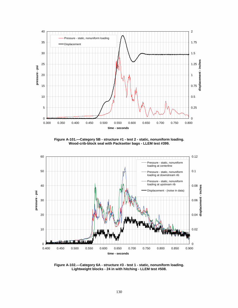
35
40 2
1.75
30
25
20
15
10
5
0
Pressure - static, nonuniform loading
Displacement
pre
ssu
re -
psi
dis
pla
cem
ent
- in
ches
1.5
1.25
1
0.75
0.5
0.25
0
0.300 0.350 0.400 0.450 0.500 0.550 0.600 0.650 0.700 0.750 0.800
time - seconds
Figure A-101.—Category 5B - structure #1 - test 2 - static, nonuniform loading. Wood-crib-block seal with Packsetter bags - LLEM test #399.
40
50
pre
ssu
re -
psi
dis
pla
cem
ent
- in
ch
es
60 0.12
Pressure - static, nonuniform loading at centerline
Pressure - static, nonuniform loading at downstream rib
Pressure - static, nonuniform loading at upstream rib
Displacement - (noise in data)
0.400 0.450 0.500 0.550 0.600 0.650 0.700 0.750 0.800 0.850 0.900
time - seconds
0.08
0.06 30
20 0.04
10 0.02
0 0
Figure A-102.—Category 6A - structure #3 - test 1 - static, nonuniform loading. Lightweight blocks - 24 in with hitching - LLEM test #508.
0.1
130

70 3.5
80 4
Pressure - static, nonuniform loading at upstream rib
Pressure - static, nonuniform loading at centerline
Displacement
0.400 0.450 0.500 0.550 0.600 0.650 0.700 0.750 0.800 0.850 0.900
time - seconds
Figure A-103.—Category 6A - structure #3 - test 2 - static, nonuniform loading. Lightweight blocks - 24 in with hitching - LLEM test #509.
60
50
40
30
20
10
0
3
2.5
2
1.5
1
0.5
0
pre
ssu
re -
psi
dis
pla
cem
ent
- in
ch
es
20
25 5
pre
ssu
re -
ps
i
dis
pla
cem
ent
- in
ches
4.5
4
3.5
3
2.5
2
1.5
1
0.5
0
15
10
5
0
Pressure - static, uniform loading
Displacement
0 0.2 0.4 0.6 0.8 1 1.2 1.4 1.6 1.8
time - seconds
Figure A-104.—Category 6A - structure #2 - test 1 - static, uniform loading. Lightweight blocks - 24 in with hitching - test 4-48.
131
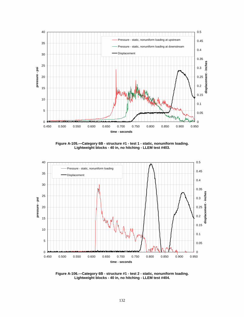
35 0.45
30
0.4
40 0.5
Pressure - static, nonuniform loading at upstream
Pressure - static, nonuniform loading at downstream
Displacement
0.450 0.500 0.550 0.600 0.650 0.700 0.750 0.800 0.850 0.900 0.950
time - seconds
Figure A-105.—Category 6B - structure #1 - test 1 - static, nonuniform loading. Lightweight blocks - 40 in, no hitching - LLEM test #403.
pre
ssu
re -
psi
dis
pla
cem
ent
- in
ch
es
25
20
15
10
5
0
0.35
0.3
0.25
0.2
0.15
0.1
0.05
0
40
35
pre
ssu
re -
psi
dis
pla
cem
ent
- in
ches
0.5
Pressure - static, nonuniform loading
Displacement
0.450 0.500 0.550 0.600 0.650 0.700 0.750 0.800 0.850 0.900 0.950
time - seconds
Figure A-106.—Category 6B - structure #1 - test 2 - static, nonuniform loading. Lightweight blocks - 40 in, no hitching - LLEM test #404.
0.45
30
25
20
15
10
5
0
0.4
0.35
0.3
0.25
0.2
0.15
0.1
0.05
0
132

35 0.45
40 0.5
30
25
20
15
10
5
0
Pressure - static, nonuniform loading
Displacement
0.4
0.35
0.3
0.25
0.2
0.15
0.1
0.05
0
pre
ssu
re -
ps
i
dis
pla
cem
en
t -
inc
he
s
0.450 0.500 0.550 0.600 0.650 0.700 0.750 0.800 0.850 0.900 0.950
time - seconds
Figure A-107.—Category 6B - structure #1 - test 3 - static, nonuniform loading. Lightweight blocks - 40 in, no hitching - LLEM test #405.
40
pre
ssu
re -
psi
dis
pla
cem
ent
- in
ches
1
35
30
25
20
15
10
5
0
Pressure - static, nonuniform loading
Displacement 0.875
0.75
0.625
0.5
0.375
0.25
0.125
0
0.450 0.500 0.550 0.600 0.650 0.700 0.750 0.800 0.850 0.900 0.950
time - seconds
Figure A-108.—Category 6B - structure #1 - test 4 - static, nonuniform loading. Lightweight blocks - 40 in, no hitching - LLEM test #406.
133

0.09
25 0.1
20
15
10
5
0
Pressure - static, nonuniform loading at centerline
Displacement - (noise in data) 0.08
0.07
0.06
0.05
0.04
0.03
0.02
0.01
0
pre
ssu
re -
psi
dis
pla
cem
ent
- in
ches
0.400 0.450 0.500 0.550 0.600 0.650 0.700 0.750 0.800 0.850 0.900
time - seconds
Figure A-109.—Category 6B - structure #2 - test 1 - static, nonuniform loading. Lightweight blocks - 40 in, no hitching - LLEM test #501.
pre
ssu
re -
psi
dis
pla
cem
ent
- in
ches
25 0.1
20
15
10
5
0
Pressure - static, nonuniform loading at centerline
Displacement - (noise in data)
0.09
0.08
0.07
0.06
0.05
0.04
0.03
0.02
0.01
0
0.400 0.450 0.500 0.550 0.600 0.650 0.700 0.750 0.800 0.850 0.900
time - seconds
Figure A-110.—Category 6B - structure #2 - test 2 - static, nonuniform loading. Lightweight blocks - 40 in, no hitching - LLEM test #502.
134

25
pre
ssu
re -
psi
dis
pla
cem
ent
- in
ches
0.1
Pressure - static, nonuniform loading at centerline 0.09
Displacement - (noise in data)
20 0.08
0.07
15 0.06
0.05
10 0.04
0.03
5 0.02
0.01
0 0
0.400 0.600 0.800 1.000 1.200 1.400 1.600 1.800 2.000 2.200 2.400
time - seconds
Figure A-111.—Category 6B - structure #2 - test 3 - static, nonuniform loading. Lightweight blocks - 40 in, no hitching - LLEM test #503.
pre
ssu
re -
psi
dis
pla
cem
ent
- in
ch
es
25 0.1
Pressure - static, nonuniform loading at centerline 0.09
Displacement - (noise in data)
20 0.08
0.07
15 0.06
0.05
10 0.04
0.03
5 0.02
0.01
0 0
0.400 0.600 0.800 1.000 1.200 1.400 1.600 1.800 2.000 2.200 2.400
time - seconds
Figure A-112.—Category 6B - structure #2 - test 4 - static, nonuniform loading. Lightweight blocks - 40 in, no hitching - LLEM test #504.
135

45 0.09
50 0.1
40
35
30
25
20
15
10
5
0
Pressure - static, nonuniform loading at centerline
Displacement - (noise in data)
0.08
0.07
0.06
0.05
0.04
0.03
0.02
0.01
0
pre
ssu
re -
ps
i
dis
pla
cem
en
t -
inc
he
s
0.400 0.450 0.500 0.550 0.600 0.650 0.700 0.750 0.800 0.850 0.900
time - seconds
Figure A-113.—Category 6B - structure #2 - test 5 - static, nonuniform loading. Lightweight blocks - 40 in, no hitching - LLEM test #505.
90
100
pre
ssu
re -
psi
dis
pla
cem
ent
- in
ches
0.1
Pressure - static, nonuniform loading at centerline
Displacement - (noise in data)
0.09
80
70
60
50
40
30
20
10
0
0.08
0.07
0.06
0.05
0.04
0.03
0.02
0.01
0
0.400 0.450 0.500 0.550 0.600 0.650 0.700 0.750 0.800 0.850 0.900
time - seconds
Figure A-114.—Category 6B - structure #2 - test 6 - static, nonuniform loading. Lightweight blocks - 40 in, no hitching - LLEM test #506.
136

80 0.08
100
Pressure - static, nonuniform loading at centerline
Displacement - (noise in data)
0.1
90 0.09
70
60
50
40
30
20
10
0
0.07
0.06
0.05
0.04
0.03
0.02
0.01
0
dis
pla
cem
en
t -
inc
he
s
pre
ssu
re -
ps
i
0.400 0.450 0.500 0.550 0.600 0.650 0.700 0.750 0.800 0.850 0.900
time - seconds
Figure A-115.—Category 6B - structure #2 - test 7 - static, nonuniform loading. Lightweight blocks - 40 in, no hitching - LLEM test #507.
150
pre
ssu
re -
ps
i
-100.400 0.450 0.500 0.550 0.600 0.650 0.700 0.750 0.800 0.850 0.900
time - seconds
Pressure - static, nonuniform loading at centerline
Pressure - static, nonuniform loading at centerline
130
110
90
70
50
30
10
Figure A-116.—Category 6B - structure #2 - tests 8 and 9 - static, nonuniform loading. Lightweight blocks - 40 in, no hitching - LLEM tests #508–509.
137

35 0.18
40 0.2
pre
ssu
re -
psi
dis
pla
cem
ent
- in
ches
30
25
20
15
10
5
0
Pressure - static, nonuniform loading
Displacement - (noise in data) 0.16
0.14
0.12
0.1
0.08
0.06
0.04
0.02
0
0.400 0.450 0.500 0.550 0.600 0.650 0.700 0.750 0.800 0.850 0.900
time - seconds
Figure A-117.—Category 6B - structure #3 - test 1 - static, nonuniform loading. Lightweight blocks - 40 in, no hitching - LLEM test #501.
pre
ssu
re -
ps
i
dis
pla
cem
ent
- in
ches
60 6
Pressure - static, nonuniform loading
Displacement
50 5
40
30
20
10
0
4
3
2
1
0
0.400 0.450 0.500 0.550 0.600 0.650 0.700 0.750 0.800 0.850 0.900
time - seconds
Figure A-118.—Category 6B - structure #3 - test 2 - static, nonuniform loading. Lightweight blocks - 40 in, no hitching - LLEM test #502.
138
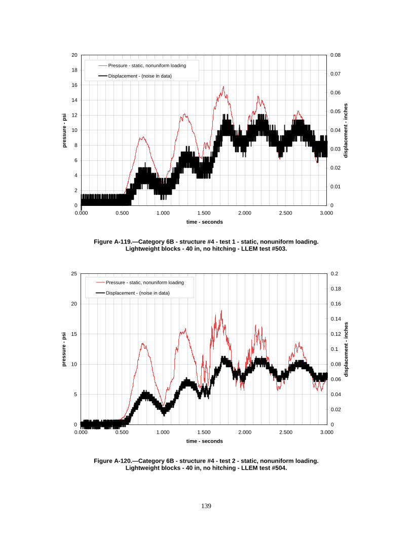
pre
ssu
re -
psi
dis
pla
cem
ent
- in
ches
20 0.08
Pressure - static, nonuniform loading 18
0.07 Displacement - (noise in data)
16
0.06
14
12 0.05
10 0.04
8 0.03
6
0.02
4
2 0.01
0 0
0.000 0.500 1.000 1.500 2.000 2.500 3.000
time - seconds
Figure A-119.—Category 6B - structure #4 - test 1 - static, nonuniform loading. Lightweight blocks - 40 in, no hitching - LLEM test #503.
pre
ssu
re -
psi
dis
pla
cem
ent
- in
ches
25 0.2
Pressure - static, nonuniform loading 0.18
Displacement - (noise in data)
20 0.16
0.14
15 0.12
0.1
10 0.08
0.06
5 0.04
0.02
0 0
0.000 0.500 1.000 1.500 2.000 2.500 3.000
time - seconds
Figure A-120.—Category 6B - structure #4 - test 2 - static, nonuniform loading. Lightweight blocks - 40 in, no hitching - LLEM test #504.
139

45 4.5
50 5
40
35
30
25
20
15
10
5
0
Pressure - static, nonuniform loading
Displacement
pre
ssu
re -
ps
i
dis
pla
cem
ent
-in
ches
4
3.5
3
2.5
2
1.5
1
0.5
0
0.400 0.450 0.500 0.550 0.600 0.650 0.700 0.750 0.800 0.850 0.900
time - seconds
Figure A-121.—Category 6B - structure #4 - test 3 - static, nonuniform loading. Lightweight blocks - 40 in, no hitching - LLEM test #505.
pre
ssu
re -
psi
dis
pla
cem
ent
-in
ches
80 8
70
60
50
40
30
20
10
0
Pressure - reflected, uniform loading at rib
Pressure - reflected, uniform loading at centerline
Displacement
7
6
5
4
3
2
1
0
0.400 0.450 0.500 0.550 0.600 0.650 0.700 0.750 0.800 0.850 0.900
time - seconds
Figure A-122.—Category 6B - structure #5 - test 1 - reflected, uniform loading. Lightweight blocks - 40 in, no hitching - LLEM test #502.
140

pre
ssu
re -
psi
dis
pla
cem
ent
- in
ches
20 0.1
Pressure - reflected, uniform loading at rib 18 0.09
Displacement - (noise in data)
16 0.08
14 0.07
12 0.06
10 0.05
8 0.04
6 0.03
4 0.02
2 0.01
0 0
0.000 0.500 1.000 1.500 2.000 2.500 3.000
time - seconds
Figure A-123.—Category 6B - structure #6 - test 1 - reflected, uniform loading. Lightweight blocks - 40 in, no hitching - LLEM test #503.
pre
ssu
re -
psi
dis
pla
cem
ent
- in
ches
25 0.2
Pressure - reflected, uniform loading at rib 0.18
Displacement - (noise in data)
20 0.16
0.14
15 0.12
0.1
10 0.08
0.06
5 0.04
0.02
0 0
0.000 0.500 1.000 1.500 2.000 2.500 3.000
time - seconds
Figure A-124.—Category 6B - structure #6 - test 2 - reflected, uniform loading. Lightweight blocks - 40 in, no hitching - LLEM test #504.
141

80 8
70 7
60
50
40
30
20
10
0
Pressure - reflected, uniform loading at rib
Displacement
pre
ssu
re -
psi
dis
pla
cem
ent
- in
ches
6
5
4
3
2
1
0
0.400 0.450 0.500 0.550 0.600 0.650 0.700 0.750 0.800 0.850 0.900
time - seconds
Figure A-125.—Category 6B - structure #6 - test 3 - reflected, uniform loading. Lightweight blocks - 40 in, no hitching - LLEM test #505.
pre
ssu
re -
psi
dis
pla
cem
ent
- in
ches
8120
100
80
60
40
20
0
Pressure - reflected, uniform loading at rib
Displacement 7
6
5
4
3
2
1
0
0.400 0.450 0.500 0.550 0.600 0.650 0.700 0.750 0.800 0.850 0.900
time - seconds
Figure A-126.—Category 6B - structure #7 - test 1 - reflected, uniform loading. Lightweight blocks - 40 in, no hitching - LLEM test #506.
142
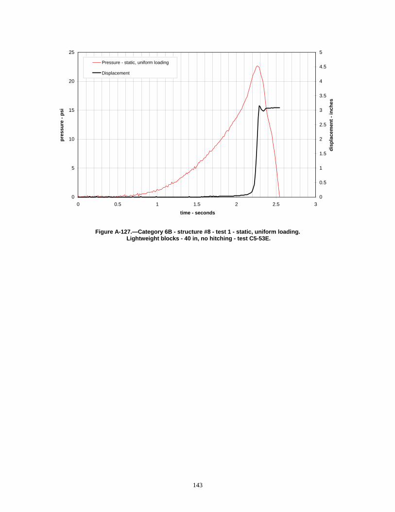
0
5
10
15
20
25
pre
ssu
re -
psi
0
0.5
1
1.5
2
2.5
3
3.5
4
4.5
5
dis
pla
cem
ent
- in
ches
Pressure - static, uniform loading
Displacement
0 0.5 1 1.5 2 2.5 3
time - seconds
Figure A-127.—Category 6B - structure #8 - test 1 - static, uniform loading. Lightweight blocks - 40 in, no hitching - test C5-53E.
143

Delivering on the Nation’s promise: safety and health at work for all people through research and prevention
To receive NIOSH documents or more information about occupational safety and health topics, contact NIOSH at
1–800–CDC–INFO (1–800–232–4636) TTY: 1–888–232–6348 e-mail: [email protected]
or visit the NIOSH Web site at www.cdc.gov/niosh.
For a monthly update on news at NIOSH, subscribe to NIOSH eNews by visiting www.cdc.gov/niosh/eNews.
DHHS (NIOSH) Publication No. 2009-151
SAFER • HEALTHIER • PEOPLE™