compatibility check of elastic critical moment … · compatibility check of elastic critical...
TRANSCRIPT

http://www.iaeme.com/IJCIET/index.asp 388 [email protected]
International Journal of Civil Engineering and Technology (IJCIET)
Volume 9, Issue 10, October 2018, pp. 388–399, Article ID: IJCIET_09_10_040
Available online at http://www.iaeme.com/ijciet/issues.asp?JType=IJCIET&VType=9&IType=10
ISSN Print: 0976-6308 and ISSN Online: 0976-6316
©IAEME Publication Scopus Indexed
COMPATIBILITY CHECK OF ELASTIC
CRITICAL MOMENT EVALUATION OF
ROLLED CHANNEL SECTION BEAM
Juned Raheem
Civil Engineering Department, Maulana Azad National Institute of Technology,
Bhopal - 462003, Madhya Pradesh, India
Dr. S.K Dubey
Civil Engineering Department, Maulana Azad National Institute of Technology,
Bhopal - 462003, Madhya Pradesh, India
Dr. Nitin Dindorkar
Civil Engineering Department, Maulana Azad National Institute of Technology,
Bhopal - 462003, Madhya Pradesh, India
ABSTRACT
Design policies for eccentrically loaded beams with open channel cross- sections
aren't available in Indian code IS 800-2000 General Construction in Steel-Code of
Practice (THIRD REVISION). General solution for Elastic Critical Moment, Mcr has
determined with the aid of the use of expression given in ANNEX-E (CL.8.2.2.1,IS
800:2007) for mono symmetric beams. Results so acquired are tested with Finite
Element (FE) simulations on the idea of a parametric take a look at the use of ANSYS
software program14.0.
A variant of maximum 0.3% is observed between the analytical end result and
ANSYS result for slender beams however a massive distinction was observed for
stocky beams. There is a reduction in design strength with an increase in span of the
beam. The strength curve for channel beam proposed by means of IS 800: 2007 seems
to be an awesome choice, however it does no longer claim to be accurate for beams
with a ratio L/h<20.
Key words: Elastic Critical Moment, Slenderness, Reduction factors and Design
beam capacity.
Cite this Article: Juned Raheem, Dr. S.K Dubey and Dr. Nitin Dindorkar,
Compatibility Check of Elastic Critical Moment Evaluation of Rolled Channel Section
Beam, International Journal of Civil Engineering and Technology (IJCIET) 9(10),
2018, pp. 388–399.
http://www.iaeme.com/IJCIET/issues.asp?JType=IJCIET&VType=9&IType=10

Compatibility Check of Elastic Critical Moment Evaluation of Rolled Channel Section Beam
http://www.iaeme.com/IJCIET/index.asp 389 [email protected]
1. INTRODUCTION
Beside mono symmetric I sections, rolled channel steel section are often used as beam to
guide light loads in the shape of purlin to support roof over truss shape, staging to support
bridge decks, etc[20] The structural conduct of channel section is different from doubly
symmetric section or mono symmetric I section because its shear centre and centre of gravity
do no longer coincide.[12] In steel structure layout of laterally unsupported beam is quite
complex because of diverse reasons consisting of lateral buckling of complete beam between
the supports, nearby buckling of flanges and longitudinal buckling of web.[19] When a beam
which is extra rigid about its major axis than its minor axis subjected to bending about its
principal axis, lateral torsional buckling will occur about the minor axis of the beam. Lateral
torsion buckling will generally tend the compression flange to buckle in the course transverse
to the load earlier than the steel yields results in pulling beam sideways, whereas the tension
flange will hold the beam in its plane.[1]
The lateral torsional buckling happens in a case for channel sections, where the shear
centre does not coincide with the vertical axis of the centre of gravity of the section.[8] The
load is generally subjected eccentrically on the web which reasons a torsional moment in the
beam, which makes it tough to discover elastic critical moment Mcr.[4] Indian standard code
for General Construction In Steel-Code Of Practice (Third Revision) IS 800-2007 has
furnished guidelines to calculate elastic lateral torsional buckling moment or theoretical
elastic critical moment for doubly symmetric section and cross section mono symmetric about
its minor axis subjected to bend about its principal axis. Indian standard code IS 800-2007
doesn’t offers any components to calculate theoretical elastic critical moment for channel
beams.[17] Whereas channel section is a mono-symmetrical section that's symmetric about its
major axis. However new design rule was already proposed for design bending ability for
channel section subjected to eccentric loading, however with restriction of span to section
depth ratio.[8]
Stability of steel beam conjointly depends on bending distribution, point of application of
load and degree of the mono symmetry of the section referred as Wagner’s parameter.[5]
Coefficients C1, C2 and C3 are respectively influenced by these parameters that are given for
a few selected load circumstances.[5] Since, because the slenderness ratio decreases, extra
fibers of the beam become inelastic (increasing the degree of plasticity) and only the elastic
element of the cross section remains potent in supplying resistance to lateral buckling.[6] In
stocky beams buckling may be ruled by distorsion of web.[7] The effect of bracing relies not
only on the stiffness of the restraint but also on the modified slenderness of the section. The
load application had more influence on elastic critical moment and this impact is of the larger
magnitude when the beam is rigid about major axis.[9] Channel section has been analysed for
Mcr, utilising 3 factor formula of Eurocode-3 and verified with diverse softwares akin to
ADINA, COLBEAM, LTBEAM, SAP2000 and STAAD pro however failed to establish any
conclusion.[11] In present state of affairs, most of the commercial Structural engineering
program consider lateral torsional buckling during the analysis of potential of steel beams.
ANSYS application as a modern day approach established on FEM simulation and modeling
is used for evolved engineering simulation rationale. The method has three phases
preprocessing, solution and postprocessing.[22].
2. METHODOLOGY
Initially, a literature study on the theory behind various instability phenomena for steel beams
was made, including study of formula given in Indian Standard codes IS: 800:2007, ANNEX
E and Clause 8.2.2 treats lateral-torsional buckling and establishes the elastic critical moment,
Mcr.

Juned Raheem, Dr. S.K Dubey and Dr. Nitin Dindorkar
http://www.iaeme.com/IJCIET/index.asp 390 [email protected]
A parametric study has been carried out wherein channel beams with targeted dimensions,
lengths and load conditions has been modeled and analyzed using FEM simulation based
computer program ANSYS workbench 14.0. Four cross sections were chosen ISMCP 125,
ISMCP150, ISMCP175 and ISMCP200 of 5 exceptional lengths i.e., 1600mm, 2200mm,
3000mm, 4000mm, and 5000mm. A uniformly dispensed load of 1KN/m is applied on each
beam on the top flange, the center and the bottom of the web respectively. Theoretical elastic
critical moment was calculated using method given in code IS: 800:2007, ANNEX E and
Clause 8.2.2 for mono symmetric section and then validated making use of ANSYS
workbench 14.0.
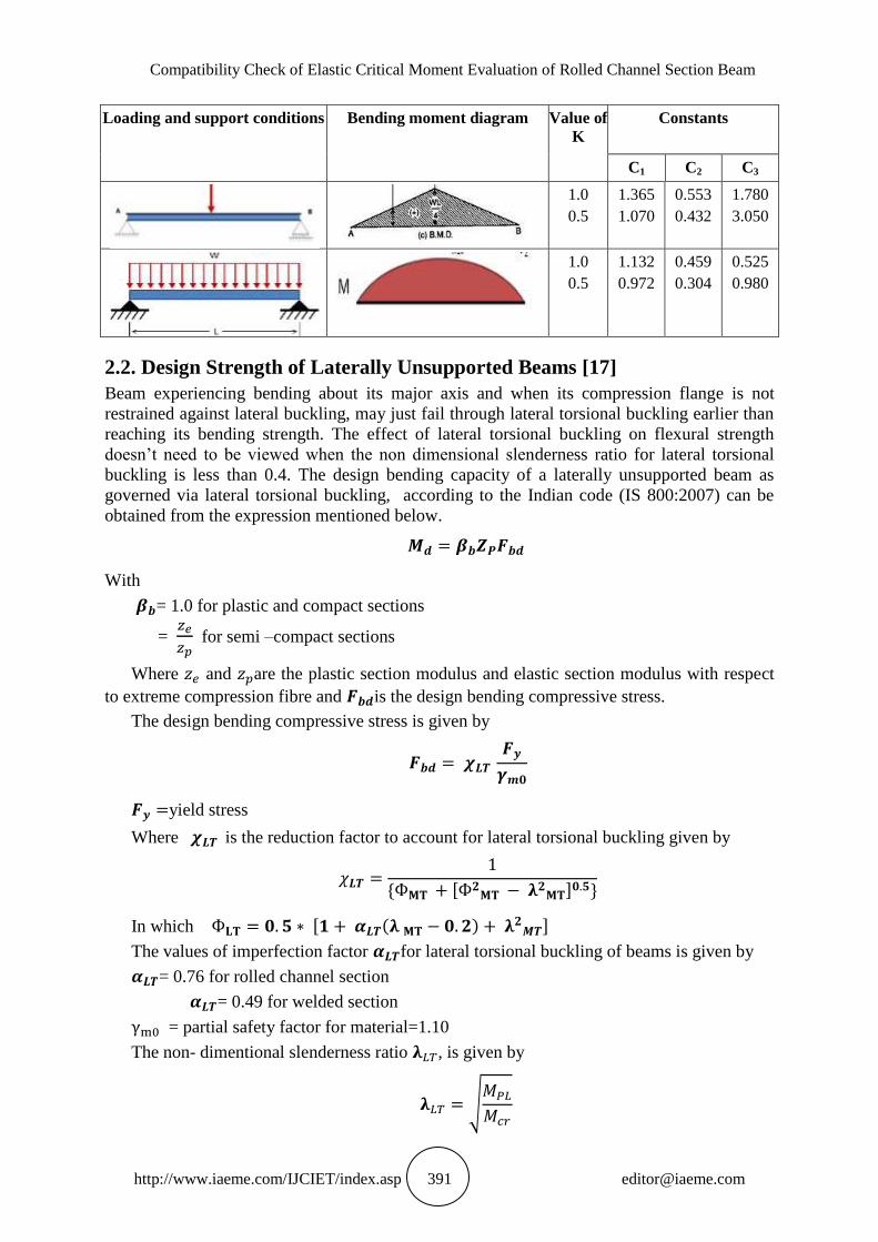
2.1. Elastic Critical Moment of a Section Symmetrical About Minor Axis[17]
The guideline is only valid for major axis bending where the cross-section is uniform and
symmetrical about the minor axis. It will for that reason no longer be 100% correct for
channel beams.
{[(
)
( )
( )
( )]
( )}
Where:
C1 = Coefficient depending on the shape of the moment diagram
C2 = Coefficient depending on the point of load application relative to the shear centre
C3 = Coefficient depending on the symmetry of the cross-section around the weak axis
K, Kw = effective length factors of the unsupported length accounting for boundary conditions
at the end lateral supports.
K = 0.5 (For complete restraint against rotation about weak axis
= 1.0 (For free rotation about weak axis)
=0.7 (For one end fixed and other end free)
Kw = Factor for warping restraint. Unless special provisions to restrain warping of the section
at the end lateral supports are made, Kw should be taken as 1.0.
yg =distance between the point of application of the load and the shear centre of the cross
section in y- direction and is positive when the load is acting towards the shear centre from the
point of application.
∫ ( )
ys = coordinate of the shear centre with respect to centroid and is positive when the shear
centre is on the compression side of the centroid.
y, z = coordinates of the elemental area with respect to centroid of the section
h = overall height of the section
Iyy = Moment of inertia around y axis ( minor axis)
Iw = Warping constant
It = Torsion constant
G= Shear Modulus
E= Youngs Modulus
Compatibility Check of Elastic Critical Moment Evaluation of Rolled Channel Section Beam
http://www.iaeme.com/IJCIET/index.asp 391 [email protected]
Loading and support conditions Bending moment diagram Value of
K
Constants
C1 C2 C3
1.0
0.5
1.365
1.070
0.553
0.432
1.780
3.050
1.0
0.5
1.132
0.972
0.459
0.304
0.525
0.980
2.2. Design Strength of Laterally Unsupported Beams [17]
Beam experiencing bending about its major axis and when its compression flange is not
restrained against lateral buckling, may just fail through lateral torsional buckling earlier than
reaching its bending strength. The effect of lateral torsional buckling on flexural strength
doesn’t need to be viewed when the non dimensional slenderness ratio for lateral torsional
buckling is less than 0.4. The design bending capacity of a laterally unsupported beam as
governed via lateral torsional buckling, according to the Indian code (IS 800:2007) can be
obtained from the expression mentioned below.
With
= 1.0 for plastic and compact sections
=
for semi –compact sections
Where and are the plastic section modulus and elastic section modulus with respect
to extreme compression fibre and is the design bending compressive stress.
The design bending compressive stress is given by
yield stress
Where is the reduction factor to account for lateral torsional buckling given by
* , - +
In which , ( ) -
The values of imperfection factor for lateral torsional buckling of beams is given by
= 0.76 for rolled channel section
= 0.49 for welded section
= partial safety factor for material=1.10
The non- dimentional slenderness ratio , is given by
√

Juned Raheem, Dr. S.K Dubey and Dr. Nitin Dindorkar
http://www.iaeme.com/IJCIET/index.asp 392 [email protected]
Where
= elastic critical moment and
= plastic moment resistance
3. PARAMETRIC STUDY
The study was conducted by considering four (Indian standard medium weight parallel flange
channel) ISMCP beams with different cross section size of ISMCP 125, ISMCP 150, ISMCP
175 and ISMCP 200.Three beams having different length of 1600mm, 2200mm, 3000mm,
4000mm and 5000mm.
The physical properties considered in the study are
Unit mass of steel, ρ =7850 kg/m
Modulus of elasticity, E=2.0 x N/ (Mpa)
Poisson ratio, μ=0.5
Modulus of rigidity, G=0.769 x N/ (Mpa)
Co-efficient of thermal expansion, x / C
3.1. Sectional Properties of Hot Rolled Beams
a) ISMCP 125 b) ISMCP 150 c) ISMCP 175 d) ISMCP 200
Table 1 Showing sectional properties if ISMCP channel sections
ISMCP 125 ISMCP 150 ISMCP 175 ISMCP 200
Depth, D
mm 125 150 175 200
Breadth, B
mm 65 75 75 75
Web thickness, t
mm 5.3 5.7 6 6.2
Flange thickness, T
mm 8.1 9.0 10.2 11.4
Root 1
mm 9.5 10 10.5 11
Root 2
mm 5 5 6 6
I xx
321 794 1240 1840
I yy
69.8 120 138 156
Mass, M
kg/m 13.1 16.8 19.6 22.3
Sectional area, a
16.7 21.3 24.9 28.5

Compatibility Check of Elastic Critical Moment Evaluation of Rolled Channel Section Beam
http://www.iaeme.com/IJCIET/index.asp 393 [email protected]
3.2. Load Case
Uniformly distributed load has been considered and applied at different levels of web at top,
middle and bottom. Load of 100 kN/m is applied for total of five different spans of beam.
Figure 1 Linearly distributed load application [15]
3.3. Boundary Condition
Beams are modelled with the boundary conditions known as fork support conditions. This
type of boundary conditions is given to allow warping in flanges and to resist torsion in the
webs at the supports.
Figure 2 Fork support condition [15]
3.4. Validation using ANSYS 14.0
Figure 3 Eigen value of ISMCP 175, 1600mm beam length [22]

Juned Raheem, Dr. S.K Dubey and Dr. Nitin Dindorkar
http://www.iaeme.com/IJCIET/index.asp 394 [email protected]
ANSYS is Finite Element software used for simulation purpose. In this study Eigen values
are evaluated for an Indian standard medium weight parallel flange channel beam by creating
its model, applying boundary condition and a uniformly distributed load of 100 KN/m. the
figure shows the buckling load factors of ISMCP 175 for different lengths
1600,2200,3000,4000 and 5000mm obtained in ANSYS.
Table 2 Variation (%M) of Elastic Critical Moment obtained theoretically, Mcr (KN-m) and using FEM
Simulation software ANSYS, M’cr (KN-m) through Eigen buckling factors, (x) w.r.t different span for different
channel section beams subjected to UDL of 1KN/m applied on Top web of the beam.
Length(mm)
ISMCP 125 ISMCP 150 ISMCP 175 ISMCP 200
x Mcr M’cr %M x Mcr M’cr %M x Mcr M’cr %M x Mcr M’cr %M
1600 0.1030 32.92 32.96 -0.12 0.1756 58.86 56.19 4.75 0.223 78.52 71.36 9.12 0.279 98.11 89.28 9.89
2200 0.0400 23.72 24.20
-
1.98 0.0653 40.38 39.51 2.20 0.0838 53.04 50.7 4.41 0.102 66.04 61.71 7.02
3000 0.0161 17.67 18.15
-
2.64 0.02574 29.207 28.96 0.85 0.033 37.95 37.13 2.16 0.04 47.14 45 4.76
4000 0.0070 13.57 14.00 -3.07 0.01089 22.11 21.78 1.52 0.01422 28.55 28.44 0.39 0.0174 35.44 34.8 1.84
5000 0.0037 11.06 11.44
-
3.32 0.005975 17.95 18.67
-
3.86 0.00744 23.11 23.25
-
0.61 0.00913 28.69 28.53 0.56
Figure 4 Graph showing variation in Elastic critical moment calculated theoretically and using ANSYS w.r.t
different span and cross section of channel section beam subjected to UDL on Top web of the beam.
Table 3 Variation (%M) of Elastic Critical Moment obtained theoretically, Mcr (KN-m) and using FEM
Simulation software ANSYS, M’cr (KN-m) through Eigen buckling factors, (x) w.r.t different span for different
channel section beams subjected to UDL of 1KN/m applied on Mid web of the beam.
Length(mm)
ISMCP 125 ISMCP 150 ISMCP 175 ISMCP 200
x Mcr M’cr %M x Mcr M’cr %M x Mcr M’cr %M x Mcr M’cr %M
1600 0.147 49.07 47.04 4.32 0.263 87.83 84.16 4.36 0.339 117.34 108.48 7.55 0.428 147.94 136.96 8.02
2200 0.053 32.4 32.07 1.03 0.0916 56.32 55.42 1.62 0.1186 74.37 71.75 3.52 0.147 93.42 88.94 5.04
3000
0.02 22.4 22.5 -
0.44 0.0336 38.11 37.8 0.82 0.0435 49.855 48.94 1.84 0.0541 62.44 60.86 2.60
4000
0.00828 16.26 16.56 -
1.81 0.01373 27.29 27.46
-
0.62 0.01766 35.46 35.32 0.40 0.02191 44.44 43.82 1.41
5000 0.004181 12.805 13.07 -
2.03 0.007 21.33 21.88 -
2.51 0.0089 27.63 27.81 -
0.65 0.0101 34.56 34.38 0.52
0.00
20.00
40.00
60.00
80.00
100.00
120.00
0 1000 2000 3000 4000 5000 6000
Elas
tic
Cri
tica
l Mo
me
nt
(KN
-m)
Length(mm)
ISMCP125 Mcr
ISMCP125 M’cr
ISMCP150 Mcr
ISMCP150 M’cr
ISMCP175 Mcr
ISMCP175 M’cr
ISMCP200 Mcr
ISMCP200 M’cr

Compatibility Check of Elastic Critical Moment Evaluation of Rolled Channel Section Beam
http://www.iaeme.com/IJCIET/index.asp 395 [email protected]
Figure 5 Graph showing variation in Elastic critical moment calculated theoretically and using
ANSYS w.r.t different span and cross section of channel section beam subjected to UDL on Mid web
of the beam.
Table 4 Variation (%M) of Elastic Critical Moment obtained theoretically, Mcr (KN-m) and using FEM
Simulation software ANSYS, M’cr (KN-m) through Eigen buckling factors, (x) w.r.t different span for different
channel section beams subjected to UDL of 1KN/m applied on Bottom web of the beam.
Length(mm)
ISMCP 125 ISMCP 150 ISMCP 175 ISMCP 200
x Mcr M’cr %M x Mcr M’cr %M x Mcr M’cr %M x Mcr M’cr %M
1600 0.206 67.91 65.92 3.02 0.382 131.04 122.24 7.20 0.49 175.35 156.8 10.58 0.621 223.1 198.72 10.93
2200 0.0697 42.22 42.17 0.12 0.126 78.56 76.23 3.06 0.164 104.26 99.22 4.83 0.207 132.16 125.24 5.24
3000
0.0247 27.62 27.79 -
0.61 0.04369 49.74 49.15 1.20 0.057 65.49 64.13 2.08 0.0716 82.7 80.55 2.60
4000
0.00978 19.16 19.56 -
2.04 0.01669 33.66 33.38 0.84 0.0219 44.05 43.8 0.57 0.0274 55.4 54.8 1.08
5000 0.004814 14.651 15.04 -
2.59 0.008344 23.35 26.08 -
10.47 0.0106 33.03 33.13 -0.30 0.01322 41.49 41.31 0.43
Figure-6 Graph showing variation in Elastic critical moment calculated theoretically and using
ANSYS w.r.t different span and cross section of channel section beam subjected to UDL on Bottom
web of the beam.
0
20
40
60
80
100
120
140
160
0 1000 2000 3000 4000 5000 6000
Elas
tic
Cri
tica
l Mo
me
nt(
KN
-m)
Length(mm)
ISMCP125 Mcr
ISMCP125 M’cr
ISMCP150 Mcr
ISMCP150 M’cr
ISMCP175 Mcr
ISMCP175 M’cr
ISMCP200 Mcr
ISMCP200 M’cr
0
50
100
150
200
250
0 1000 2000 3000 4000 5000 6000
Elas
tic
Cri
tica
l Mo
me
nt(
KN
-m)
Length(mm)
ISMCP125 Mcr
ISMCP125 M’cr
ISMCP150 Mcr
ISMCP150 M’cr
ISMCP175 Mcr
ISMCP175 M’cr
ISMCP200 Mcr
ISMCP200 M’cr

Juned Raheem, Dr. S.K Dubey and Dr. Nitin Dindorkar
http://www.iaeme.com/IJCIET/index.asp 396 [email protected]
Table 5 Variation of Elastic Critical Moment (%M) obtained theoretically and using FEM Simulation
software ANSYS w.r.t different L/D ratio for different channel section beams subjected to UDL of
1KN/m applied on Top web of the beam.
L/D
RATIO
ISMCP125
%M L/D
ISMCP150
%M L/D
ISMCP175
%M L/D
ISMCP200
%M
12.80 -0.12 10.67 4.75 9.14 9.12 8.00 9.89
17.60 -1.98 14.67 2.20 12.57 4.41 11.00 7.02
24.00 -2.64 20.00 0.85 17.14 2.16 15.00 4.76
32.00 -3.07 26.67 1.52 22.86 0.39 20.00 1.84
40.00 -3.32 33.33 -3.86 28.57 -0.61 25.00 0.56
Figure 7 Graph showing variation in Elastic critical moment calculated theoretically and using ANSYS w.r.t
different L/D ratio of channel section beam subjected to UDL on Top web of the beam.
Table 6 Variation of Elastic Critical Moment (%M) obtained theoretically and using FEM Simulation software
ANSYS w.r.t different L/D ratio for different channel section beams subjected to UDL of 1KN/m applied on
Mid web of the beam.
L/D
ISMCP125
%M L/D
ISMCP150
%M L/D
ISMCP175
%M L/D
ISMCP200
%M
12.80 4.32 10.67 4.36 9.14 7.55 8.00 8.02
17.60 1.03 14.67 1.62 12.57 3.52 11.00 5.04
24.00 -0.44 20.00 0.82 17.14 1.84 15.00 2.60
32.00 -1.81 26.67 -0.62 22.86 0.40 20.00 1.41
40.00 -2.03 33.33 -2.51 28.57 -0.65 25.00 0.52
Figure 8 Graph showing variation in Elastic critical moment calculated theoretically and using ANSYS w.r.t
different L/D ratio of channel section beam subjected to UDL on Mid web of the beam.
-6.00
-4.00
-2.00
0.00
2.00
4.00
6.00
8.00
10.00
12.00
0.00 10.00 20.00 30.00 40.00 50.00%V
AR
IATI
ON
of
Mcr
L/D RATIO
ISMCP125 %M
ISMCP150 %M
ISMCP175 %M
ISMCP200%M
-4.00
-2.00
0.00
2.00
4.00
6.00
8.00
10.00
0.00 10.00 20.00 30.00 40.00 50.00% V
AR
IATI
ON
of
Mcr
L/D RATIO
ISMCP125 %M
ISMCP150 %M
ISMCP175 %M
ISMCP200%M

Compatibility Check of Elastic Critical Moment Evaluation of Rolled Channel Section Beam
http://www.iaeme.com/IJCIET/index.asp 397 [email protected]
Table 7 Variation of Elastic Critical Moment (%M) obtained theoretically and using FEM Simulation
software ANSYS w.r.t different L/D ratio for different channel section beams subjected to UDL of
1KN/m applied on Bottom web of the beam.
L/D
ISMCP125
%M L/D
ISMCP150
%M L/D
ISMCP175
%M L/D
ISMCP200
%M
12.80 3.02 10.67 7.20 9.14 10.58 8.00 10.93
17.60 0.12 14.67 3.06 12.57 4.83 11.00 5.24
24.00 -0.61 20.00 1.20 17.14 2.08 15.00 2.60
32.00 -2.04 26.67 0.84 22.86 0.57 20.00 1.08
40.00 -2.59 33.33 -10.47 28.57 -0.30 25.00 0.43
Figure 9 Graph showing variation in Elastic critical moment calculated theoretically and using ANSYS w.r.t
different L/D ratio of channel section beam subjected to UDL on Bottom web of the beam.
Note:
Theoretical formula of Elastic critical moment is calculated using mono symmetric beam
formula
{[(
)
( )
( )
( )]
( )}
Elastic critical moment (ANSYS) =( )
( )
4. CONCLUSIONS
In the current study various factors which will affect the lateral torsional buckling have been
analyzed using codal formula given in IS: 800: 2007 ANNEX E in Clause 8.2.2.1 and
validated with ANSYS simulation program which works on Finite element method. After
analyzing the factors, the elastic critical moment, Mcr, have been evaluated for the four
different Indian standard medium weight channel section (ISMCP),cross section details taken
from Hot rolled steel section given in IS:808-1989.
The conclusions are presented below:
It is observed that mono symmetric formula in IS 800:2007 is giving elastic critical moment
conservative results vis-à-vis ANSYS result for slender beams but showing large variation for
stocky beams.
The results obtained from the IS code formula is compatible with ANSYS results for beams
having length to depth ratio between range 20 to 40.
-15.00
-10.00
-5.00
0.00
5.00
10.00
15.00
0.00 10.00 20.00 30.00 40.00 50.00
% V
AR
IATI
ON
of
Mcr
L/D RATIO
ISMCP125 %M
ISMCP150 %M
ISMCP175 %M
ISMCP200%M

Juned Raheem, Dr. S.K Dubey and Dr. Nitin Dindorkar
http://www.iaeme.com/IJCIET/index.asp 398 [email protected]
Stocky beams having length to depth ratio less than 20 is showing a percentage variation more
than 5%.
The stocky beams have much higher post yielding capacity than slender beams.
The results obtained from ISCODE stipulation are on the safer side for slender beams for
design purpose.
REFERENCES
[1] Clark, J. W. and Hill, H. N. [1960], “Lateral Buckling of Beams”, J. of the Structural
Division, Vol. 86, No. ST7, July 1960, ASCE, pp. 175-196.
[2] Peköz, T, “Lateral Buckling Of Singly Symmetric Beams” Eleventh International
Specialty Conference on Cold-Formed Steel Structures St. Louis, Missouri, U.S.A.,
October (1992) 20-21.
[3] Trahair N.S. (1993): Flexural-Torsional Buckling of Structures, CRC Press, Boca Raton,
1993
[4] Salmon, C.G., and J.E. Jhonson[1996], Steel Structures, Design and Behavior, 4th edn,
Harper Collins, NY, 1996, P.1024.
[5] F. Mohri , A. Brouki, J.C. Roth, “Theoretical and numerical stability analyses of
unrestrained, mono-symmetric thin-walled beams” Journal of Constructional Steel
Research, Vol. 59 (2003), pp. 63–90.
[6] Amin Mohebkhah, “The moment-gradient factor in lateral– torsional buckling on
inelastic castellated beams” Journal of Constructional Steel Research, Vol. 60 (2004), pp.
1481–1494.
[7] Avik Samanta, Ashwini Kumar, “Distortional buckling in monosymmetric I-beams”
Thin-Walled Structures 44 (2006), pp. 51–56
[8] H.H. (Bert) Snijder , J.C.D. (Hans) Hoenderkamp , M.C.M (Monique) Bakker
H.M.G.M.(henri) Steenbergen C.H.M.(Karini) de Louw “Design rules for lateral
torsional buckling of channel sections subjected to web loading” Stahlbau 77 (2008), pp.
247-256
[9] Martin Ahnlén, Jonas Westlund ”Lateral Torsional Buckling of I-beams” Division of
Structural Engineering Steel and Timber Structures Chalmers University Of Technology
Göteborg, Sweden Master’s Thesis 2013:59 (2013)
[10] R. Kandasamy , R. Thenmozhi , L.S.Jeyagopal “Flexural -Torsional Buckling Tests of
Cold-Formed Lipped Channel Beams Under Restrained Boundary Conditions”
International Journal of Engineering and Technology (IJET), Vol 6, No 2 Apr-May
(2014), pp. 1176-1187
[11] Hermann Þór Hauksson, Jón Björn Vilhjálmsson “Lateral-Torsional Buckling of Steel
Beams with Open Cross Section” Division of Structural Engineering Steel and Timber
Structures Chalmers University Of Technology Göteborg, Sweden 2014 Master’s Thesis
2014:28 (2014)
[12] L. Dahmani, S. Drizi, M. Djemai, A. Boudjemia, M. O. Mechiche ”Lateral Torsional
Buckling of an Eccentrically Loaded Channel Section Beam” World Academy of Science,
Engineering and Technology, International Journal of Civil and Environmental
Engineering, Vol:9, No:6, pp. 689-692 (2015)
[13] Jan Barnata, Miroslav Bajera, Martin Vilda, Jindřich Melchera, Marcela Karmazínováa,
Jiří Pijáka “Experimental Analysis of Lateral Torsional Buckling of Beams with Selected
Cross-Section Types” Procedia Engineering, 195 (2017), pp. 56–61

Compatibility Check of Elastic Critical Moment Evaluation of Rolled Channel Section Beam
http://www.iaeme.com/IJCIET/index.asp 399 [email protected]
[14] Amin Mohebkhah , Mojtaba G.Azandariani “Lateral-torsional buckling resistance of
unstiffened slender-web plate girders under moment gradient” Thin-Walled Structures,
102(2016), pp. 215–221
[15] Carl-Marcus Ekström, David Wesley, ”Lateral-torsional Buckling of Steel Channel
Beams” Division of Structural Engineering Chalmers University Of Technology
Gothenburg, Sweden 2017 Master’s Thesis 2017:52 (2017)
[16] Karan Singh Saini “Lateral Torsional Buckling Of Hot Rolled Steel Beams” Division of
Structural Engineering Maulana Azad National Institute of Technology, Bhopal, India
Master’s Thesis (2017)
[17] IS 800 : 2007 General construction in steel – code of practice (third edition)
[18] Dimensions for Hot rolled steel beam, column, channel and angle sections ( Third
Revision ) IS 808-1989
[19] Subramanian, ”Design Of steel Structures”, Textbook
[20] .Ramchandra, ”Design Of steel Structures”, Textbook
[21] Timoshenko S.P. and Gere J. (1961): Theory of Elastic Stability (2nd ed.), McGraw-Hill,
New York, 1961
[22] ANSYSSoftwarehttp://www.ansys.stuba.sk/html/guide_55/g-str/GSTR7.htm