compass series cooling towers - baltimore air...
TRANSCRIPT
Compass Series Cooling TowersOPERATION & MAINTENANCE MANUAL
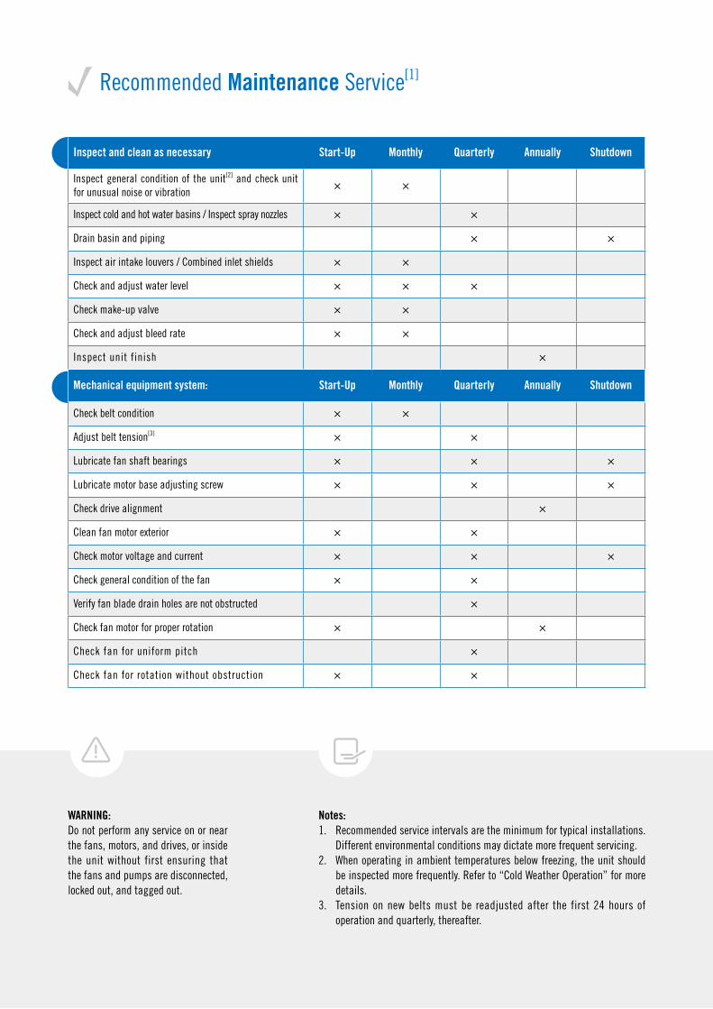
Recommended Maintenance Service[1]
Notes:1. Recommended service intervals are the minimum for typical installations.
Different environmental conditions may dictate more frequent servicing. 2. When operating in ambient temperatures below freezing, the unit should
be inspected more frequently. Refer to “Cold Weather Operation” for more details.
3. Tension on new belts must be readjusted after the first 24 hours of operation and quarterly, thereafter.
WARNING:Do not perform any service on or near the fans, motors, and drives, or inside the unit without first ensuring that the fans and pumps are disconnected, locked out, and tagged out.
Inspect and clean as necessary Start-Up Monthly Quarterly Annually Shutdown
Inspect general condition of the unit[2] and check unit for unusual noise or vibration
× ×
Inspect cold and hot water basins / Inspect spray nozzles × ×
Drain basin and piping × ×
Inspect air intake louvers / Combined inlet shields × ×
Check and adjust water level × × ×
Check make-up valve × ×
Check and adjust bleed rate × ×
Inspect unit finish ×
Mechanical equipment system: Start-Up Monthly Quarterly Annually Shutdown
Check belt condition × ×
Adjust belt tension[3] × ×
Lubricate fan shaft bearings × × ×
Lubricate motor base adjusting screw × × ×
Check drive alignment ×
Clean fan motor exterior × ×
Check motor voltage and current × × ×
Check general condition of the fan × ×
Verify fan blade drain holes are not obstructed ×
Check fan motor for proper rotation × ×
Check fan for uniform pitch ×
Check fan for rotation without obstruction × ×
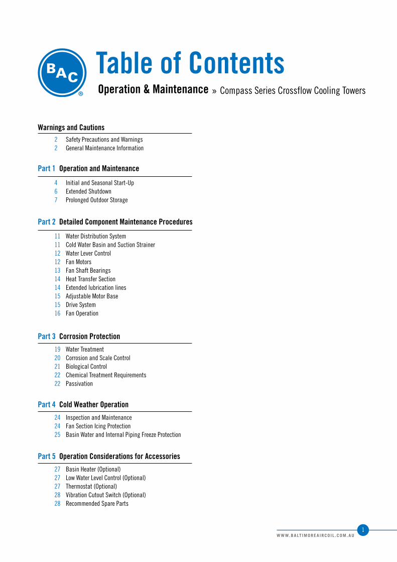
Table of ContentsOperation & Maintenance » Compass Series Crossflow Cooling Towers
Warnings and Cautions
Part 3 Corrosion Protection
Part 4 Cold Weather Operation
Part 5 Operation Considerations for Accessories
Part 1 Operation and Maintenance
Part 2 Detailed Component Maintenance Procedures
2 Safety Precautions and Warnings2 General Maintenance Information
19 Water Treatment20 Corrosion and Scale Control21 Biological Control22 Chemical Treatment Requirements22 Passivation
24 Inspection and Maintenance24 Fan Section Icing Protection25 Basin Water and Internal Piping Freeze Protection
27 Basin Heater (Optional)27 Low Water Level Control (Optional)27 Thermostat (Optional)28 Vibration Cutout Switch (Optional)28 Recommended Spare Parts
4 Initial and Seasonal Start-Up6 Extended Shutdown7 Prolonged Outdoor Storage
11 Water Distribution System11 Cold Water Basin and Suction Strainer12 Water Lever Control12 Fan Motors13 Fan Shaft Bearings14 Heat Transfer Section 14 Extended lubrication lines15 Adjustable Motor Base15 Drive System16 Fan Operation
1W W W. B A LT I M O R E A I R C O I L . C O M . A U
Safety Precautions & Warnings:
General Maintenance Information
WARNING: Before performing any maintenance or inspection, or performing service on or near fans, drives, motors or inside the unit, make certain that all power has been disconnected and locked in the off position.WARNING: When the fan speed of the unit is to be changed from the factory set speed, including changes achieved by the use of a variable fan speed device, steps must be taken to avoid operation at or near the fan’s “critical speed” which could result in fan failure and possible personal injury or damage. Consult with your local BAC Representative on any such applications.WARNING: The recirculation water system may contain chemicals or biological contaminants, including Legionella, which could be harmful if inhaled or ingested. Personnel exposed directly to the discharge airstream and the associated drift mists, generated during operation of the water distribution system and/or fans, or mists produced by high pressure water jets or compressed air (if used to clean components of the recirculation water system), must wear respiratory protection equipment approved for such use by governmental occupational safety and health authorities.Safety PrecautionsOnly qualified personnel may operate, maintain, and repair this equipment. All such personnel must be thoroughly familiar with the equipment, the associated system and controls, and procedures in this manual. Use proper care, procedure, and tools when handling, lifting, installing, operating, maintaining, and repairing this equipment to prevent personal injury and/or property damage.CAUTION: StorageBAC units are typically installed immediately after shipment, and many operate year round. However, if the unit is to be stored for a prolonged period of time either before or after installation, certain precautions should be observed. For instance, covering the unit with a clear plastic tarpaulin during storage can trap heat inside the unit, potentially causing damage to the fill and other plastic components. If units must be covered during storage, an opaque, reflective tarp should be used. Consult with your local BAC Representative for additional recommendations on long-term storage. For normal seasonal shutdowns, refer to the applicable section in this manual.CAUTION: All electrical, mechanical, and rotating machinery are potential hazards, particularly for those not familiar with their design, construction, and operation. Accordingly, use appropriate lockout procedures. Adequate safeguards (including the use of protective enclosures where necessary) should be taken with this equipment both to safeguard the public from injury and to prevent damage to the equipment, its associated system, and the premises.CAUTION: This equipment should never be operated without all fan screens, access panels, and access doors in place. For the protection of authorized service and maintenance personnel, install a lockable disconnect switch located within sight of the unit on each fan.CAUTION: Never use chloride or chlorine based solvents such as bleach or muriatic (hydrochloric) acid to clean stainless steel. It is important to rinse the surface with warm water and wipe with a dry cloth after cleaning.Caution: Follow your local safety regulations when working inside or on top of the unit.It is important to rinse the surface with warm water and wipe with a dry cloth after cleaning.
The services required to maintain a cooling tower are primarily a function of the quality of the air and water in the locality of the installation.Air:The most harmful atmospheric conditions are those with unusual quantities of industrial smoke, chemical fumes, salt, or heavy dust. Such airborne impurities are carried into the cooling tower and absorbed by the recirculating water to form a corrosive solution.Water:The most harmful conditions develop as water evaporates from the cooling tower, leaving behind the dissolved solids originally contained in the make-up water. These dissolved solids may be either alkaline or acidic and, as they are concentrated in the circulating water, can produce scaling or accelerated corrosion.The extent of impurities in the air and water determines the frequency of most maintenance services and also governs the extent of water treatment which can vary from a simple continuous bleed and biological control to a sophisticated treatment system. (See sections on “Water Treatment” and “Biological Control”)
2W W W. B A LT I M O R E A I R C O I L . C O M . A U
Operation and MaintenanceInitial and Seasonal Start-Up
Extended Shutdown
Prolonged Outdoor Storage
Compass Series Crossflow Cooling Towers
Initial and Seasonal Start-Up
Summary● Ensurethefanandsystempumpmotorshavebeendisconnected
andlockedout.
● Conductexternalinspectionoftheequipment.Checkforleaks,corrosion,andanystructuraldamage.
● Inspectpipingandconnections.
Cleaning● Drainthecoldwaterbasin(withbasinstrainersinplace).
● Openthehotwaterbasincoversandremoveanydirtordebrisfromthehotwaterbasins.
● Cleanandinspectthefandeck.
● Removedirtanddebrisfromthefanguard(s).
● Inspectandcleanallspraynozzles
● Cleanandinspectthemechanicalcomponents,suchasthefanandmotor.
● Flushthecoldwaterbasintoremoveanyaccumulateddirtanddebris.
● Removethesuctionstrainer,cleanandreinstall.
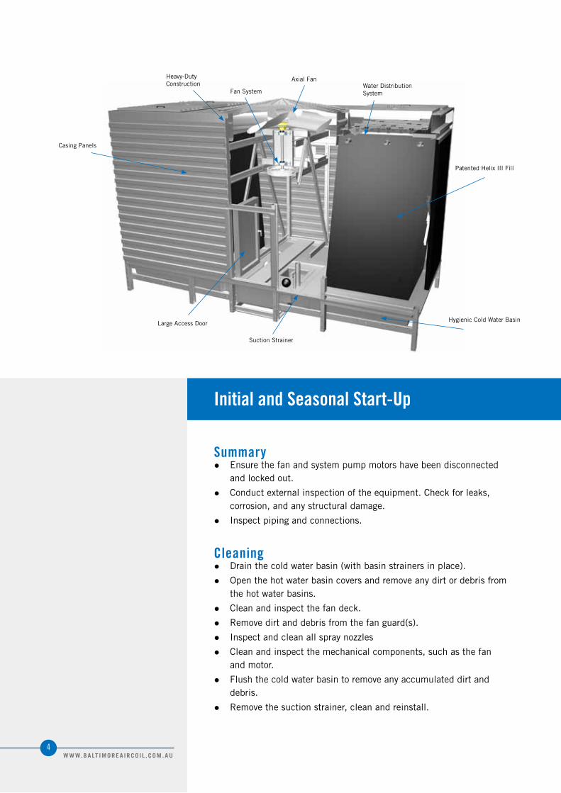
CasingPanels
Heavy-DutyConstruction
FanSystem
AxialFan
SuctionStrainer
LargeAccessDoor
WaterDistributionSystem
PatentedHelixIIIFill
HygienicColdWaterBasin
4W W W. B A LT I M O R E A I R C O I L . C O M . A U

Initial and Seasonal Start-upSummaryCleaningInspectionStart-up
Operation and Maintenance
CAUTION:
1. Rapid on-off cycling can cause the fan motor to overheat. It is recommended that the controls be set to allow a maximum of 6 on-off cycles per hour.
2. When using a 2-speed motor, the starter should include a 15-second time delay when switching from high speed to low speed.
Figure 1. Water Distribution System
Inspection● Thoroughlyinspectthefanforanydamage.
● Electricalcurrentshouldbemeasuredduringwarmambientconditionsandwithaheatloadonthetower.Afterprolongedshutdowns,themotorinsulationshouldbecheckedwithaninsulationtesterpriortorestartingthemotor.
● Atseasonalstart-up,checkandadjustthebelttensiononthefandrivesystem.
● Turnthefan(s)byhandtoinsurerotationwithoutobstruction.
● Bumpthefanmotor(s)andcheckforproperfanrotation.
● Checkfloatoperatedmake-upvalvetobesureitisoperatingfreely.
Start-Up● Lubricatethefanshaftbearingspriortoseasonalstart-up.(See
Page 13 formoredetails)
● Atstart-up,whenthecoldwaterbasiniscompletelydrained,fillthecoldwaterbasinwithfreshwatertotheoverflowlevel.Fornewinstallations,initiatethebiocidewatertreatmentprogramatthistime(Seesectionon“BiologicalControl”).Atseasonalstartup,andfollowingashutdownperiodofmorethan3days,resumethebiocidetreatmentprogramoradministerashocktreatmentofappropriatebiocidespriortooperatingthecoolingtowerfanstoeliminateaccumulatedbiologicalcontaminants(Seesectionon“BiologicalControl”)
5W W W. B A LT I M O R E A I R C O I L . C O M . A U
Extended Shutdown
Thefollowingservicesshouldbeperformedwheneverthecoolingtoweristobeshut-downformorethan3days:
● Disconnect,lockout,andtagoutallfansandpumps.
● Drainthecoldwaterbasinandallpipingthatwillbeexposedtofreezingtemperatures.
● Cleanandflushthehotandcoldwaterbasinswiththebasinstrainersinplace.Leavethecoldwaterbasindrainopensorainandmeltingsnowwilldrainfromthetower.
● Cleanthebasinstrainersandreinstall.
● Coverthefandischargeopeningtokeepoutdirtanddebris.
● Lubricatethefanshaftbearingsandmotorbaseadjustingscrew.
● Closetheshut-offvalveinthemake-upwaterline(suppliedbyothers)anddrainallexposedmake-upwaterpiping.
● Inspecttheintegrityofthecorrosionprotectionsystemonthesteelportionofthetower.(Seesectionon“CorrosionandScaleControl”)
● Securethefanmotorstartingdeviceintheoffposition.Ifinspectionorrepairrequiresservicepersonneltoworkaroundeitherthefanordrivesduringshutdown,apersonalsafetyhazardexistsifthisprecautionisnottaken.
● Setthefloatonthemake-upvalvetoclosethevalvewhenthefloatisapproximately12.7mmbelowtheoverflowlevel.
● Startthesystemwaterpump.
● Balanceflowtothehotwaterbasinsbyadjustingtheflowbalancingvalves(providedbyothers),multi-cellarrangementswillrequireflowbalancingbetweencellstoobtainevenwaterdistribution.
● Openthevalveinthetowerbleedlineandadjustbleed.(Seesectionson“WaterTreatmentControl”)
● Checkthevoltageandcurrentofallthreephasesofthefanmotor.Thecurrentshouldnotexceedthenameplaterating.
● Checktheoptionalvibrationcut-outswitch.(SeePage 28formoredetails)
DANGER:
Do not perform any service on or near the fans, motors, and drives, or inside the unit without first ensuring that the fans and pumps are disconnected, locked out and tagged out.
After 24 Hours:
After 24 hours of operation under thermal load, the following services should be performed:
1. Check the tower for any unusual noise or vibration.
2. Check the operation water level in the hot and cold water basins and adjust balancing valves.
3. Readjust the belt tension.
6W W W. B A LT I M O R E A I R C O I L . C O M . A U

Prolonged Outdoor Storage
Routine Start-Up/Shutdown Water System Control● Start-up
Inviewofthecoldwaterbasinwaterstorage,donotturntheoutletvalveopeningtothemaxatthebeginning.Increasethevalveopeningaccordingtothewaterlevelofthecoldbasintoavoiddrawingairthroughthewaterpump.Ensurethewaterlevelofthecoldwaterbasinisapproximatelybelowtheoverflowlevel.
● Shutdown
Inviewofthecoldwaterbasinwaterstorage,donotclosetheoutletvalvedirectly.Decreasethevalveopeningslowtoavoidoverflow.Letexcesswateroutfromoverflowpipe.(addition)
Storage Preparation ● Conductthe“ExtendedShutdown”procedureonpage6iftheunit
isinstalled.
● Ensurethecoldwaterbasinisfullydrainedandthedrainisopen.
● Forstoragepriortoinstallation,allcomponentsandaccessories,whichsometimesshipinsidethetowerandarenotapermanentfixtureinthebasin,shouldberemovedandstoredindoors.
● Removeandstorefanbelts(ifsupplied)atroomtemperature.Tagbeltsappropriatelyforfutureidentification.
● Applyaweather-resistantlubricantorheavygreasesuchasAnti-Seizetoallexposedthreadedorflangedconnectionsandadjustablemotorbasethreadedrod.
● Inspecttheprotectivefinishontheunit.Cleanandrefinishasrequired.
Initial and Seasonal Start-UpStart-UpExtended ShutdownRoutine Start-Up/Shutdown Water System ControlProlonged Outdoor StorageStorage Preparation
Operation and Maintenance
ATTENTION:
Covering the unit with a clear plastic tarpaulin during storage can trap heat inside the unit and cause damage to the PVC components. If units must be covered during storage, an opaque, reflective tarp should be used.
7W W W. B A LT I M O R E A I R C O I L . C O M . A U
Motor Recommendations BACstandardmotorsaredesignedforstorageatambienttemperaturesof-28.9ºCto40ºC(-20ºFto104ºF).Prolongedperiodsofexposureaboveorbelowthesespecifiedconditionscoulddegradecomponentsofthemotorandcausemalfunctionorprematurefailure.
● Motorsshouldberemovedandstoredinsidewheneverpossible.Whenindoorstorageisnotpossiblethemotorsmustbecoveredwithatarpaulin.Donotuseplasticorplasticfilm.Thiscovershouldextendbelowthemotorandbesecured;however,itshouldnottightlywrapthemotor.Thiswillallowthecaptiveairspacetobreathe,minimizingformationofcondensation.
● Caremustalsobetakentoprotectthemotorfromfloodingorfromharmfulchemicalvapors.
● Thestorageareashouldbefreefromambientvibration.Excessivevibrationcancausebearingdamage.
● Precautionsshouldbetakentopreventrodents,snakes,birds,orothersmallanimalsfromnestinginsidethemotors.Inareaswheretheyareprevalent,precautionsmustalsobetakentopreventinsectsfromgainingaccesstotheinteriorofthemotor.
● Ifnotstoredindoorsinacontrolledenvironment,someformofheatingmustbeutilizedtopreventcondensationfromaccumulatinginthemotor.Thisheatingshouldmaintainthewindingtemperatureataminimumof-12.8ºC(9ºF)abovetheambienttemperatureofthesurroundingenvironment,keepingitfromdroppingbelowthedewpointwherecondensationcouldforminsidethemotor.Ifspaceheatersaresupplied,theyshouldbeenergized.RequesttherequiredvoltageandtransformercapacityfromyourlocalBACRepresentative.Athirdoptionistouseanauxiliaryheatsourceandkeepthewindingwarmbyeitherconvectionorblowingwarmairintothemotor.
● Rotatethemotorshaftmonthlytoredistributebearinggrease.
DANGER:
Do not perform any service on or near the fans, motors and drives, or inside the unit without first ensuring that the fans and pumps are disconnected, locked out and tagged out.
8W W W. B A LT I M O R E A I R C O I L . C O M . A U
DANGER:
Do not perform any service on or near the fans, motors and drives, or inside the unit without first ensuring that the fans and pumps are disconnected, locked out and tagged out.
Maintenance Requirements Rotateallfansandmotorshaftsmonthlybyhand.Hand-turningwillensurethattheshaftsandbearingsarefreeandwillredistributegreasewithinthebearings.Keephandsawayfrompinchpointssuchasboltsandsheaves.
Inspectthecoldwaterbasinmonthlytoensurethatthedrainisopenandremoveanyleavesordebristhatmayhaveaccumulatedinthecoldwaterbasin.
Inspectaxialfanspriortostart-upandatleastonceannuallytoensurethatthebladesaretightandthatthereisnoobviouscorrosionbetweenthehubandthefanblade.
Inspecttherustpreventativecoatingonallmotorexternalmachinedsurfacesincludingshaftextensionsmonthly.Ifnecessary,re-coatthesurfaceswithRUSTVETO®.
Start-Up Preparation After Prolonged Storage Keepinmindthatstart-upproceduresafterlongperiodsofstoragearejustasimportantaspre-shutdownprocedures.
● Motorsshouldbethoroughlyinspectedandcleanedandrestoredtopre-storagecondition.
● Inspecttheaxialfanpriortostart-uptoensurethatthebladesaretightandthatthereisnoobviouscorrosionbetweenthehubandthefanblades.Donotenergizethefanifthereisobviouscorrosionoffancomponents.Loosefanbladescouldresultinfanfailureandpossibleinjuryordamage.
● Reinstallallfanbelts,motors,doorgaskets,anddrainplugs(asapplicable),andremoveallprotectivecoverings.
● Forunitsstoredpriortoinstallation,conductriggingproceduresasdirectedintheunit’sRigging and Assembly Instructions,availablebycontactingyourlocalBACRepresentative.
● Performaninsulationtestofmotorwindingstoensuresatisfactoryinsulationresistance.
● Conductfullstart-upprocedureasstatedinthe“Start-UpProcedure”onpage 4.Beespeciallythoroughforcleaningandinspectionpriortostart-up.
Prolonged Outdoor StorageMotor RecommendationsMaintenance RequirementsStart-Up Preparation After Prolonged Storage
Operation and Maintenance
9W W W. B A LT I M O R E A I R C O I L . C O M . A U

Detailed Component Maintenance Procedures
Compass Series Crossflow Cooling Towers
Water Distribution System
Cold Water Basin and Suction Strainer
Water Lever Control
Fan Motors
Fan Shaft Bearings
Heat Transfer Section
Extended Lubrication Lines
Adjustable Motor Bases
Drive System
Fan Operation
Thesystemwaterentersthecoolingtowerthroughthehotwaterbasin(s).Atdesignflow,theoperationlevelshouldnotbelessthan89mmandnotgreaterthan140mmdeep.Quarterly,ormoreoftenasrequired,removeanydirtordebriswhichmayclogthenozzles.Seasonallycleanandflushthehotwaterbasinwithfreshwater.
Water Distribution System
Cold Water Basin and Suction Strainer
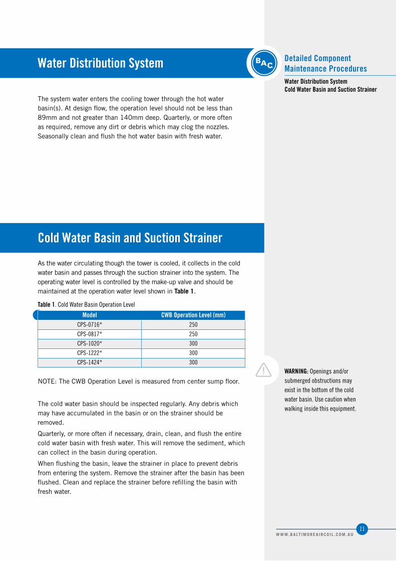
Asthewatercirculatingthoughthetoweriscooled,itcollectsinthecoldwaterbasinandpassesthroughthesuctionstrainerintothesystem.Theoperatingwaterleveliscontrolledbythemake-upvalveandshouldbemaintainedattheoperationwaterlevelshowninTable 1.
Model CWB Operation Level (mm)CPS-0716* 250
CPS-0817* 250
CPS-1020* 300
CPS-1222* 300
CPS-1424* 300
NOTE:TheCWBOperationLevelismeasuredfromcentersumpfloor.
Thecoldwaterbasinshouldbeinspectedregularly.Anydebriswhichmayhaveaccumulatedinthebasinoronthestrainershouldberemoved.
Quarterly,ormoreoftenifnecessary,drain,clean,andflushtheentirecoldwaterbasinwithfreshwater.Thiswillremovethesediment,whichcancollectinthebasinduringoperation.
Whenflushingthebasin,leavethestrainerinplacetopreventdebrisfromenteringthesystem.Removethestrainerafterthebasinhasbeenflushed.Cleanandreplacethestrainerbeforerefillingthebasinwithfreshwater.
Table 1. Cold Water Basin Operation Level
WARNING: Openings and/or submerged obstructions may exist in the bottom of the cold water basin. Use caution when walking inside this equipment.
Water Distribution SystemCold Water Basin and Suction Strainer
Detailed ComponentMaintenance Procedures
11W W W. B A LT I M O R E A I R C O I L . C O M . A U
Water Level Control
Fan Motors
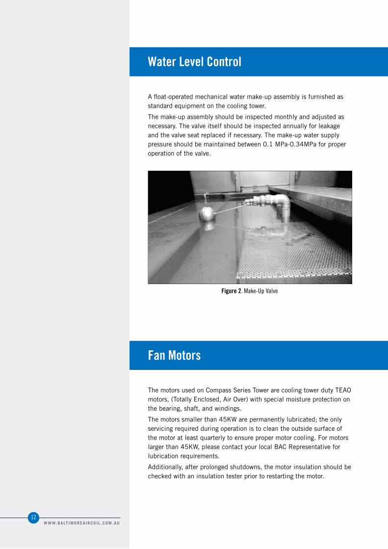
Afloat-operatedmechanicalwatermake-upassemblyisfurnishedasstandardequipmentonthecoolingtower.
Themake-upassemblyshouldbeinspectedmonthlyandadjustedasnecessary.Thevalveitselfshouldbeinspectedannuallyforleakageandthevalveseatreplacedifnecessary.Themake-upwatersupplypressureshouldbemaintainedbetween0.1MPa-0.34MPaforproperoperationofthevalve.
ThemotorsusedonCompassSeriesTowerarecoolingtowerdutyTEAOmotors,(TotallyEnclosed,AirOver)withspecialmoistureprotectiononthebearing,shaft,andwindings.
Themotorssmallerthan45KWarepermanentlylubricated;theonlyservicingrequiredduringoperationistocleantheoutsidesurfaceofthemotoratleastquarterlytoensurepropermotorcooling.Formotorslargerthan45KW,pleasecontactyourlocalBACRepresentativeforlubricationrequirements.
Additionally,afterprolongedshutdowns,themotorinsulationshouldbecheckedwithaninsulationtesterpriortorestartingthemotor.
Figure 2. Make-Up Valve
12W W W. B A LT I M O R E A I R C O I L . C O M . A U
Fan Shaft Bearings
Twopillowblockballbearingssupportthefanshaft.Eachbearingisequippedwithalubricationfittingandaslinger/lockingcollartokeepoutmoisture.
Inspection & MaintenanceOnlylubricatethebearingswithamanualgreasegunorBAC’soptionalAutomaticBearingGreaser.Donotusehigh-pressuregreasegunssincetheymayrupturethebearingseals.
Onlylubricatethebearingswithoneofthefollowingcompatiblewaterresistantgreaseswhicharesuitableforambienttemperaturesrangingfrom-53.9ºC(-65ºF)to+121.1ºC(+250ºF).
-Amoco-RyconPremium#3
-Chevron-SRI
-MobilGrease®-#28
-MobilGrease®-SHC32
-Shell-Alvania#3
-Shell-Dolium“R”
-Texaco–AFB2
Lubricatethebearingsasfollows:
-InitialStart-up:Normally,nolubricationisrequiredsincethebearingshavebeenlubricatedatthefactorypriortoshipment.However,ifthecoolingtowerhasbeenstoredatthejobsiteormorethanthreemonths,bothbearingsshouldbelubricatedwithnewgreasebeforeinitialoperation.Whenlubricating,purgetheoldgreasefromthebearingbygraduallyaddinggreaseuntilabeadofnewgreaseappearsatthesealontheundersideofthebearing.
-SeasonalStart-up:Purgethebearingswithnewgreasepriortostart-up.
-Operation:Purgethebearingswithnewgreaseeverythreemonthswhileinoperation,or2,000hours,whichevercomesfirst.
-ExtendedShutdown:Purgethebearingswithnewgreasebeforeandafteranyprolongedstorageordowntime.
Water Level ControlFan MotorsFan Shaft BearingsInspection & Maintenance
Detailed ComponentMaintenance Procedures
CAUTION: Donotusegreasewhichcontainsdetergent.Graphiteofthebearingsleevewillbetakenawayandbearingwillloseitseffectiveness.Donotscrewthewell-turnedadjustingscreworyouwillbreakthecoaxialityofthebearing.
13W W W. B A LT I M O R E A I R C O I L . C O M . A U
Heat Transfer Section
Extended Lubrication Lines
Fill & Drift Eliminator TheCompassSerieshasPVCfillwithintegraldrifteliminators.
Inspection & Maintenance Inspectandcleanthefillwiththeintegraleliminatorsatleastquarterly.
Theinspectionprocedureisasfollows:
-Shut-offthefanandthesystempump.
-Inspectthefillforobstructions,damageandfouling.
Removeanyobstructionsfromthefill.
Removeanyminorfoulingchemically.Contactyourlocalwatertreatmentconsultantforadvice.
Majorfoulingrequirescleaningandflushing.
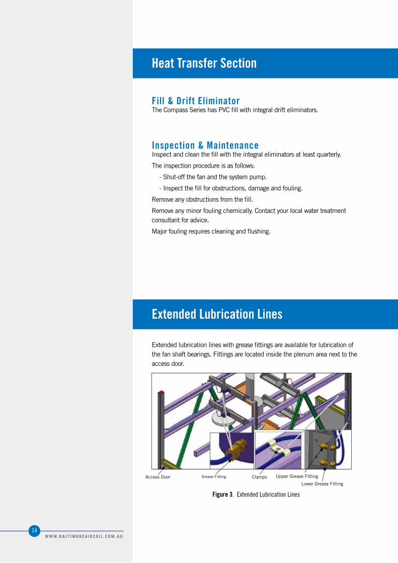
Extendedlubricationlineswithgreasefittingsareavailableforlubricationofthefanshaftbearings.Fittingsarelocatedinsidetheplenumareanexttotheaccessdoor.
AccessDoor GreaseFitting Clamps UpperGreaseFitting
LowerGreaseFitting
Figure 3. Extended Lubrication Lines
14W W W. B A LT I M O R E A I R C O I L . C O M . A U

Adjustable Motor Base
Themotorbaseslidesandadjustingscrewsshouldbecoatedtwiceayearusingagoodqualitygreasesuchasthoserecommendedforlubricatingthefanshaftbearings.
Heat Transfer SectionFill & Drift EliminatorInspection & MaintenanceExtended Lubrication LinesAdjustable Motor BaseDrive SystemInitial Start-Up & Seasonal Start-UpOperation
Detailed ComponentMaintenance Procedures
Figure 4. Adjustable Motor Base
Drive System
Initial Start-Up & Seasonal Start-UpCheckandre-adjustthebelttensionpriortoinitialstart-uporseasonalstart-up.
OperationAftertheinitialtowerstart-uportheinstallationofanewbelt,thetensionmustbereadjustedafterthefirst24hoursofoperation.Thereafter,theconditionofthebeltshouldbecheckedmonthlyandthetensionadjustedasnecessary,butatleastonceeverythreemonths.Tocheckthebelttension,placeastraightedgealongthebeltfromsheavetosheaveasshowninFigure 5aoruseatapemeasureasshowninFigure 5btomeasurebeltdeflection.Applyamoderateforcebyhand(approximately18.1kg/40lbs)evenlyacrossthewidthofthebeltinthecenterofthespanbetweenthesheaves.Ifthebeltdeflectsbetween6.35mmand9.52mmasshowninFigure 5aand5b,thebeltisadequatelytensioned.
15W W W. B A LT I M O R E A I R C O I L . C O M . A U
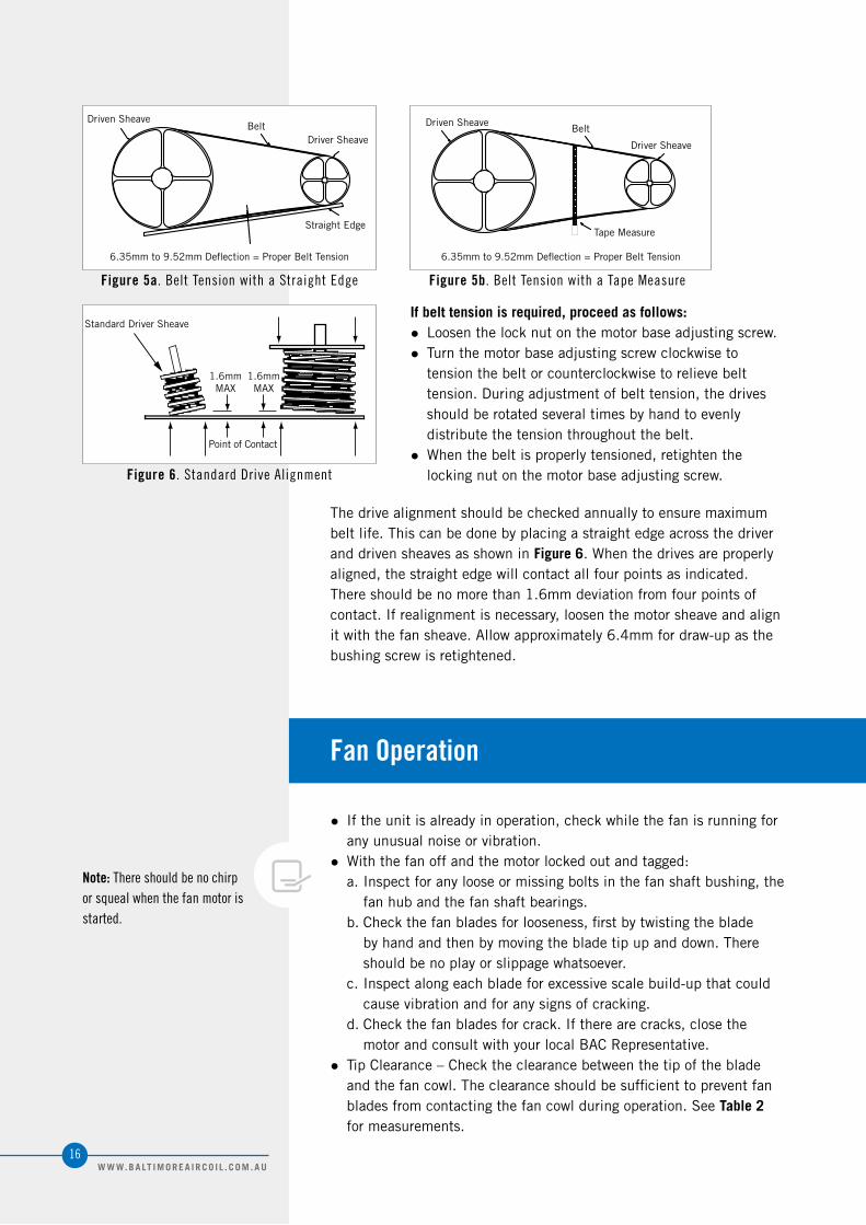
Figure 6. Standard Drive Alignment
Figure 5a. Belt Tension with a Straight Edge Figure 5b. Belt Tension with a Tape Measure
Fan Operation
● Iftheunitisalreadyinoperation,checkwhilethefanisrunningforanyunusualnoiseorvibration.
● Withthefanoffandthemotorlockedoutandtagged:a.Inspectforanylooseormissingboltsinthefanshaftbushing,the
fanhubandthefanshaftbearings.b.Checkthefanbladesforlooseness,firstbytwistingtheblade
byhandandthenbymovingthebladetipupanddown.Thereshouldbenoplayorslippagewhatsoever.
c.Inspectalongeachbladeforexcessivescalebuild-upthatcouldcausevibrationandforanysignsofcracking.
d.Checkthefanbladesforcrack.Iftherearecracks,closethemotorandconsultwithyourlocalBACRepresentative.
● TipClearance–Checktheclearancebetweenthetipofthebladeandthefancowl.Theclearanceshouldbesufficienttopreventfanbladesfromcontactingthefancowlduringoperation.SeeTable 2formeasurements.
Note: There should be no chirp or squeal when the fan motor is started.
If belt tension is required, proceed as follows:● Loosenthelocknutonthemotorbaseadjustingscrew.● Turnthemotorbaseadjustingscrewclockwiseto
tensionthebeltorcounterclockwisetorelievebelttension.Duringadjustmentofbelttension,thedrivesshouldberotatedseveraltimesbyhandtoevenlydistributethetensionthroughoutthebelt.
● Whenthebeltisproperlytensioned,retightenthelockingnutonthemotorbaseadjustingscrew.
Thedrivealignmentshouldbecheckedannuallytoensuremaximumbeltlife.ThiscanbedonebyplacingastraightedgeacrossthedriveranddrivensheavesasshowninFigure 6.Whenthedrivesareproperlyaligned,thestraightedgewillcontactallfourpointsasindicated.Thereshouldbenomorethan1.6mmdeviationfromfourpointsofcontact.Ifrealignmentisnecessary,loosenthemotorsheaveandalignitwiththefansheave.Allowapproximately6.4mmfordraw-upasthebushingscrewisretightened.
DrivenSheave
DriverSheave
StandardDriverSheave
1.6mmMAX
1.6mmMAX
PointofContact
DrivenSheave
DriverSheave
StraightEdgeTapeMeasure
Belt Belt
6.35mmto9.52mmDeflection=ProperBeltTension 6.35mmto9.52mmDeflection=ProperBeltTension
16W W W. B A LT I M O R E A I R C O I L . C O M . A U

● DrainHoles–Onhollowblades,thedrainholeinthebladetipshouldbeunobstructed.(Tip:Useapieceofwiretoprobethehole).
● BladePitch–Checktoensurethatthebladesareallatthesamepitch.Ifuncertain,measurethepitchwithaninclinometer.Fanbladedataisavailableinassemblyinstruction.ThetoleranceisasTable 3:
● Rotation–Turnthefanbyhandtoensurethatitmovesfreelywithoutroughspots,blindingorothermalfunctionsthatcouldcausevibrationorfanmotoroverload.Whilerotatingthefan,checkthebladetracking.Allbladesshouldbewithina25.4mmbandatanysinglepointaroundthecowl.
● DirectionofRotation–Oninitialstart-up,orifthefanmotorhasbeenrewiredforsomereason,bumpthefanmotorandnotethedirectionofrotation.Itshouldrotateinthedirectionindicatedbythearrowonthefancowl.
● Operation–Oninitialstart-up,runthefaninthemanualpositionforseveralminutesandcheckforanyunusualnoisesorvibration.
● VFDOperationApplicationsutilizingvariablefrequencydrives(VFDs)forfanmotorcontrolmustuseinverterdutymotorsbuiltincompliancewithIECstandard.Operationoftheunitataspeedwhichresonateswithcomponentsofthedrivesystemorsupportstructuremayresultinvibrationswhichcoulddamagethecomponentsorstructure,and/orcreateobjectionablenoise.Therefore,theseresonantspeedrangesshouldbeidentifiedatstart-upandlockedouttopreventoperationofthemotorattheseresonantspeeds.PleasecontactwithyourlocalBACRepresentativefortestingtheresonantspeed.Pleaserefertothemanufacturer’svariablefrequencydriverecommendedstart-upprocedureforfurtherinformationorconsultwithyourlocalBACRepresentativeforanyVFDapplications.
Fan Operation
Operation and Maintenance
Model Tip Clearance (mm)CPSC-0716* 11±6CPSC-0817* 13±6CPSC-1020* 13.5±6CPSC-1222* 18.5±9CPSC-1424* 19±9
Model Blade Pitch ToleranceCPSC-0716* +0°/-0.3°
CPSC-0817* +0°/-0.3°CPSC-1020* +0°/-0.3°CPSC-1222* +0°/-0.3°CPSC-1424* +0°/-0.3°
Table 2. Tip Clearance
Table 3. Fan Blade Pitch Tolerance
17W W W. B A LT I M O R E A I R C O I L . C O M . A U
Corrosion ProtectionWater Treatment
Corrosion and Scale Control
Biological Control
Chemical Treatment Requirements
Passivation
Compass Series Crossflow Cooling Towers
Corrosion ProtectionWater Treatment
BACproductsareconstructedofcorrosion-resistantmaterials.Thefillismadeofapolyvinylchloride(PVC),whichisnotsusceptibletorot,decay,rustorbiologicalattack.Othermaterialslistedbelowareusedintheequipmentconstruction:
•Fiberglass Reinforced Polyester (FRP) Components:CompassSeriesCoolingTowersareprovidedwithFRPcoldwaterbasins,fancowls,andvariousothercomponentsasstandard.Inspectthecoldwaterbasinsforaccumulationofdirtandcleanthemwithsoapandwaterasnecessary.
Aproperwatertreatmentprogram,administeredunderthesupervisionofacompetentwatertreatmentspecialist,isanessentialpartofroutinemaintenancetoensurethesafeoperationandlongevityofevaporativecoolingequipment,aswellasothersystemcomponents.
Inevaporativecoolingproducts,coolingisaccomplishedbyevaporatingasmallportionoftherecirculatingwaterasitflowsthroughtheunit.Asthewaterevaporates,thedissolvedsolids,originallypresentinthewater,remainbehindandifnotcontrolled,theconcentrationofdissolvedsolidswillincreaserapidly.Thiscanleadtocorrosion,scale,orbiologicalfoulingwhichmaynegativelyaffectheattransferaswellasthelongevityofsystemcomponents.Awatertreatmentprogrammustcontrolthefollowingsituations:
•Corrosion–Anyformofcorrosionmayaffectthelongevityofsystemcomponents.
•Scale Formation–Scalenotonlyreducesheattransferandsystemefficiency,butalsomayleadtounderdepositcorrosion.Ifscaleisnotcontrolled,itmaycontinuebuildingoncriticalcomponentssuchasthefillandseverelyimpactthermalperformance.
•Biological Fouling–Slimeandalgaeformationsmayreduceheattransfer,promotecorrosion,andharborpathogenssuchasLegionella.
Corrosion Protection Water Treatment
NOTE: Sincethequalityoftheambientairandmake-upwatervariessignificantlyfromjobsitetojobsite,BACstronglyrecommendsobtainingtheservicesofacompetentwatertreatmentspecialistpriortotheinitialstart-upoftheevaporativecoolingequipment.Additionally,toprotectagainsttheriskofLegionellacontamination,neveroperatethecoolingequipmentwithoutadequatebiologicalcontrol.
19W W W. B A LT I M O R E A I R C O I L . C O M . A U
Note:
1.Galvanizedsteelunitsrequirepassivationinordertopreventwhiterust(referto“Passivation”onpage22).
2.Hardnessandalkalinitylimitsmaybeexceededundercertaincircumstances.Consultyourwatertreatmentspecialistforrecommendations.
3.Theconversionfactorusedtodetermineconductivityis0.625(TDS=0.625xConductivity).
Corrosion and Scale Control
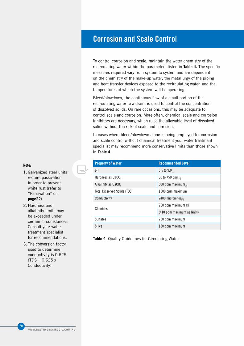
Tocontrolcorrosionandscale,maintainthewaterchemistryoftherecirculatingwaterwithintheparameterslistedinTable 4.Thespecificmeasuresrequiredvaryfromsystemtosystemandaredependentonthechemistryofthemake-upwater,themetallurgyofthepipingandheattransferdevicesexposedtotherecirculatingwater,andthetemperaturesatwhichthesystemwillbeoperating.
Bleed/blowdown,thecontinuousflowofasmallportionoftherecirculatingwatertoadrain,isusedtocontroltheconcentrationofdissolvedsolids.Onrareoccasions,thismaybeadequatetocontrolscaleandcorrosion.Moreoften,chemicalscaleandcorrosioninhibitorsarenecessary,whichraisetheallowablelevelofdissolvedsolidswithouttheriskofscaleandcorrosion.
Incaseswherebleed/blowdownaloneisbeingemployedforcorrosionandscalecontrolwithoutchemicaltreatmentyourwatertreatmentspecialistmayrecommendmoreconservativelimitsthanthoseshowninTable 4.
Property of Water Recommended Level
pH 6.5 to 9.0[1]
Hardness as CaCO3 30 to 750 ppm[2]
Alkalinity as CaCO3 500 ppm maximum[2]
Total Dissolved Solids (TDS) 1500 ppm maximum
Conductivity 2400 micromhos[3]
Chlorides250 ppm maximum Cl
(410 ppm maximum as NaCl)
Sulfates 250 ppm maximum
Silica 150 ppm maximum
Table 4.QualityGuidelinesforCirculatingWater
20W W W. B A LT I M O R E A I R C O I L . C O M . A U
Biological ControlCorrosion and Scale ControlBiological Control
Corrosion Protection
Thewarm,oxygenandnutrientrichenvironmentinsideevaporativecoolingequipmentprovidesanidealenvironmentforthegrowthofalgae,slime,andothermicro-organisms.Uncontrolled,thiscanreduceheattransfer,promotecorrosion,andpromotethegrowthofpotentiallyharmfulorganismssuchasLegionella.
ToavoidbiologicalcontaminationandminimizetheriskofLegionella,initiatethebiocidetreatmentprogramatstart-upandcontinueonaregularbasisthereafterinaccordancewiththetreatmentsupplier’sinstructions.
Introducesolidorgranularbiocidesthroughachemical“pot”feederinstalledinparallelwiththesystemcirculatingpump.Dilutedliquidbiocidesmaybeaddeddirectlytothecoldwaterbasin.
Ifozonewatertreatmentisused,atnopointshouldconcentrationsexceed0.5ppmtoavoidcorrosion.
21W W W. B A LT I M O R E A I R C O I L . C O M . A U
Chemical Treatment Requirements
Passivation
Chemicaltreatmentprogramsmustmeetthefollowingrequirements:
Thechemicalsmustbecompatiblewiththeunitmaterialsofconstructionaswellasothermaterialsusedinthesystem(pipe,heatexchanger,etc.).
Chemicalscaleandcorrosioninhibitors,particularlyacid(ifused),shouldbeintroducedintothecirculatingwaterthroughautomaticfeeders.Thisshouldbedoneatapointinthesystemwheretotalmixinganddilutionoccurbeforereachingtheevaporativecoolingequipment.Thepreferredinjectionpointforchemicalscaleandcorrosioninhibitorsisonthedischargesideofthesystemcirculatingpump(s).Thesechemicalsshouldnotbebatch-feddirectlyintotheunit’scoldwaterbasinorwaterdistributionsystem,asthiscanseverelydamageareasdirectlycontacted.
Whenchlorineisaddedtothesystem,freeresidualchlorineshouldnotexceed1ppm,exceptduringstart-upifbiologicalshocktreatmentisutilizedduringtreatment.Referto“Start-Up”onpage 4forlimits.Exceedingthislimitmayacceleratecorrosion.
Passivationistheformationofaprotective,passive,carbonatelayerongalvanizedsteelsurfaces.
Toprovidemaximumprotectionfromcorrosiononnewlyinstalledunitstakespecialmeasurestopassivategalvanizedsteelsurfaces.
Toensureproperpassivationofthegalvanizedsteel,keepthePHofthecirculatingwaterbetween7.0to8.2forfourtoeightweeksafterstart-up,oruntilnewzincsurfacesturndullgrayincolor.
IfwhiterustformsongalvanizedsteelsurfacesafterthePHisreturnedtonormalservicelevels,itmaybenecessarytorepeatthepassivationprocess.
22W W W. B A LT I M O R E A I R C O I L . C O M . A U
Cold Weather OperationInspection and Maintenance
Fan Section Icing Protection
Basin Water and Internal Piping Freeze Protection
Compass Series Crossflow Cooling Towers
4
Inspection and Maintenance
Fan Section Icing Protection
BACproductscanbeoperatedatsubfreezingambienttemperaturesprovidedproperoperatingmethodsareestablishedanddiligentlyfollowed.
• Carryoutfrequentvisualinspectionsandroutinemaintenanceservicesduringoperationinsubfreezingweather.
• Ensureallcontrolsforcapacityandfreezeprotectionaresetproperlyandfunctioningnormally.
• Preventexcessivelyhighwaterlevelsandpossibleoverflowofthecoldwaterbasinduetooverpumping,cloggedstrainers,ormake-upvalvemalfunction.
• Someuniticingcanbeexpectedinverycoldweather.Usuallythiswillnoteffecttheoperationoftheunit.Resolveanyicingconditionsthatmaydamagetheunitorthesupports,impairthesystemperformance,orcreateasafetyhazard.
Therearetwobasicoperationalmethodswhichcanbeusedtoprovidethesystem’srequiredcooling:temperaturesettingandfancontrol.Themethodofcontrolemployedonagivenapplicationdependsupontheclimaticextremeswhichareexpected,thevariationsinheatloadthatwillbeencountered,andthecompatibilityofthecontrolsystemwithotherportionsoftheinstallation.
Insubfreezingambienttemperatures,effectiveicingcontrolmayrequireacombinationofthesetwomethods.Operateeachunitwiththehighestthermalloaditcanhandle,ratherthanevenlydividingthetotalheatloadacrossallcells.Duringprolongedcoldweatherperiods,bypasstheidleunitsanddrainthebasins.
Temperature SettingLowleavingfluidtemperaturespromoteiceformation.Duringoperationinsubfreezingambienttemperatures,maintaintheleavingwatertemperatureashighaspossible.Ensuretheunitoperateswiththemaximumpossibleheatload.Therecommendedminimumprocessfluidtemperature6.1°C.
24W W W. B A LT I M O R E A I R C O I L . C O M . A U
Basin Water and Internal Piping Freeze Protection
Cold Water Basin ProtectionItisimportanttoprotectthebasinandinternalpiping.Thebasinwatercouldfreezewhentheunitisshut-downandexposedtosubfreezingambienttemperatures.
• Basin Heaters:Onapplicationswithoutaremotesump,heatmustbeprovidedtothecoldwaterbasin.Electricalimmersionheaterscanprovidetherequiredfunction.ContactyourlocalBACRepresentativefordetails.
Cold Weather OperationInspection & MaintenanceFan Section Icing ProtectionTemperature SettingFan ControlBasin Water and Internal Piping Freeze ProtectionCold Water Basin Protection
Fan ControlThefollowingarefancontrolmethodstoreducingicing:
• Multi-Speed Motors:Iftheunitisequippedwith2-speedmotors,operationatalowerspeedmaybesufficienttopreventicing.Themotorstartershouldincludeaminimum15secondtimedelaywhenswitchingfromhightolowspeed.
• Fan Cycling:Setthecontrolstoallowamaximumofsixon-offcyclesperhour.Cyclethefanoffforfiveminutesevery15to20minutesforeachcell.Ificecontinuestobuildontheairintake,decreasetheon-time.Observetheairintakeoftheunitatleasteveryfourtoeighthours.
• Fan Reversal:Thisprocedureshouldbeusedonlyaftertheothermethodsoffancontrolfail.Ifutilized,thefansshouldberuninreversefornolongerthan20minutesatnomorethan50%speed,andthecoolingtowershouldbeobservedduringthistime.Beforereturningtonormaloperation,visuallyinspectthefanbladesforiceformation.
NOTE: ModulatingthewaterflowratetotheunitisNOTarecommendedmethodofcontrollingcoolingcapacity.
25W W W. B A LT I M O R E A I R C O I L . C O M . A U

Operation Considerations for AccessoriesBasin Heater (Optional)
Low Water Level Switch (Optional)
Thermostat (Optional)
Vibration Cutout Switch (Optional)
Recommended Spare Parts
Compass Series Crossflow Cooling Towers
5
Basin Heater (Optional)
Low Water Level Switch (Optional)
Thermostat (Optional)
Oneormoreelectricimmersionheaterspreventthecoldwaterbasinfromcompletelyfreezingoveranddamagingtheunitduringshutdownorstandby.Theheatersaresizedforthespecificunit.Theheatingelementhasanenclosurethatissuitableforoutdooruse.Annually,inspectthebasinheaterpriortotheriskofreachingfreezingoperatingconditions.
OperationEnsurethattheheatingelementiscompletelysubmergedbeforeenergizingthemaindisconnect.
Lowwaterleverswitchmustbeusedinconjunctionwithheater.Theheateriscutoffautomaticallywhenthecoldbasinhasalowwaterlevel.
Lowwaterleverswitchmustbeusedinconjunctionwithheater.Theheateriscutoffautomaticallywhenthewatertemperatureishigherthanthesetting.
Operation Considerations for AccessoriesBasin Heater (Optional)OperationLow Water Level Switch (Optional)Thermostat (Optional)
Attention: Thebasinheaterisnotdesignedtopreventicingduringunitoperation.
27W W W. B A LT I M O R E A I R C O I L . C O M . A U
Vibration Cutout Switch (Optional)
TheMechanicalVibrationCutoutSwitchshouldbetestedandfieldadjustedatstart-upandyearlythereafter.
SetPointAdjustmentWhenInstalled:
• Forsafety,turnoff,thenlockandtag-outtheelectricalsupplytothefanmotor(s).
• Turnadjustmentscrewcounterclockwise1/8turnatatimeuntilyouhearthecontroltrip.
• Oncetripped,rotateadjustmentscrew1/4turnclockwise.Pushinthemanualresetbutton.
• Startupthefan(s)todetermineifthestart-upwillcausethecut-outswitchtotrip.
• IftheVCOSdoesnottrip,startandstopthefantwomoretimes.IftheVCOSstilldoesnottrip,thencalibrationiscomplete.
• IftheVCOStrips,turnoff,thenlockandtagouttheelectricalsupplytothefanmotor(s).Adjustthesetpointscrewanadditional1/4turnclockwise,andpushinthemanualresetbutton.Startupthefanmotor(s)todetermineifthestart-upwillcausetheVCOStotrip.RepeatthisadjustmentprocessuntiltheVCOSnolongertripswhentheunitisoperated.Makesuretolockoutandtagouttheelectricalsupplytothefanmotor(s)beforeenteringtheunitorre-settingtheswitch,eachtimeanadjustmenttotheVCOSismade.Afterthefinaladjustmenthasbeenmade,startandstopthefanmotor(s)twomoretimestoensurethattheVCOSisproperlyset.
28W W W. B A LT I M O R E A I R C O I L . C O M . A U
Recommended Spare Parts
BAC’sFactoryAuthorizedPartsaremanufacturedtomeetrigourouscoolingtowerdutyspecificationsandareguaranteedtofityourunitandperformasoriginalequipment.
BACisproudtointroduceCoolingTowerWorld,theonlyplacetopurchaseBACFactoryAuthorizedPartsonline.AllCoolingTowerPartsareshippedseconddayandcarryafull1-yearwarrantybackedbyBAC.
BACFactoryAuthorizedPartscanalsobeorderedthroughyourlocalBACRepresentative.Inaddition,mostBACRepresentativesmaintainalocalinventoryofcommonlyusedparts.Forafreeunitinspection,callyourlocalBACRepresentativetoday.
Evenwiththisfastdeliverycapability,itisstillrecommendedthatcertainessential,emergencyrepairpartsbemaintainedinyourlocalinventorytominimizeanypotentialdowntime.
Basic Recommended Spare Parts•Bearingset•Floatvalveorrepairkit•belts•Spraynozzlekit•Basinheaterandheatercontrols(lowwaterlevelswitch,thermalstat)•Strainer•Fanandsheavebushings•Extendedlubricationlines
Parts to Consider if Extended Downtime is a Concern•Axialfan•Fanshaft•Sheaveset•Fanmotor
Operation Considerations for AccessoriesVibration Cutout Switch (Optional)Recommended Spare Parts
29W W W. B A LT I M O R E A I R C O I L . C O M . A U

COOLING TOWERS
CLOSED CIRCUIT COOLING TOWERS
ICE THERMAL STORAGE
EVAPORATIVE CONDENSERS
HYBRID PRODUCTS
PARTS & SERVICES
w w w . B a l t i m o r e A i r c o i l . c o m . a u
120 Wisemans Ferry Road, Somersby NSW 2250 › Telephone (Australia): 1300.134.622 › Telephone (New Zealand): 0800.225.842