comparison of reinforced and fiber slab
TRANSCRIPT

Saimaa University of Applied Sciences Technology, Lappeenranta Double Degree Program in Civil and Construction Engineering Samsonov Sergei COMPARISON OF REINFORCED AND FIBER SLAB Bachelor`s Thesis 2018

ABSTRACT Sergei Samsonov Comparison of reinforced and fiber slab, 50 pages Saimaa University of Applied Sciences Double Degree Program in Civil and Construction Engineering Bachelor`s Thesis 2018 Instructors: Lecturer Petri Himmi, Saimaa University of Applied Sciences G.M. Alexander Alekseev, «Gradient Ltd.» Saint-Petersburg
This study was commissioned by «Gradient Ltd.». The purpose of the study was to analyze and calculate different variants of reinforcement of concrete slabs. The main objective of the research was to compare the total costs, strength properties, and material consumptions. The data for this study was collected from Russian norms and European literature for designers. The calculations are based on official Russian norms SP 52-104-2006 «Steel fibre reinforced concrete structures», SP 63.13330.2017 «Concrete structures», SP 20.13330.2017 «Loads and actions». The results of the calculations show the possibility of replacement of ordinary reinforcement with combined. Combined reinforcement is a combination of bar and fiber reinforcement, with the preservation of the longitudinal bars as working. Keywords: Fiber reinforcement, ribbed slab, combined reinforcement

3
TABLE OF CONTENTS TERMINOLOGY ................................................................................................. 4 1 INTRODUCTION ............................................................................................. 5
1.1 General information. ................................................................................... 5 1.1 Task description. ......................................................................................... 7 1.2 Methodology. .............................................................................................. 7
2 THEORETICAL BACKGROUND ..................................................................... 7 2.1 Composition of fiber-reinforced concrete. ................................................... 7
3 CALCULATION OF NORMAL REINFORCED SLAB. .................................... 15 3.1 Slab flange calculation. ............................................................................. 17 3.2 Calculation of the intermediate transverse rib. .......................................... 20 3.3 Longitudinal rib calculation. ....................................................................... 24 3.4 Longitudinal ribs calculation according to SLS. ......................................... 32
4 CALCULATION OF FIBER REINFORCED CONCRETE SLAB ..................... 35 4.1 Calculation of the reduced cross section of the fiber reinforced concrete . 36 4.2 Longitudinal ribs calculation according to SLS. ......................................... 42
5 COMPARISON OF TWO TYPES OF SLAB .................................................. 45 6 CONCLUSION ............................................................................................... 48 FIGURES .......................................................................................................... 49 TABLES ............................................................................................................ 49 REFERENCES ................................................................................................. 50

4
TERMINOLOGY Fiber-reinforced concrete - is concrete containing fibers that are uniformly
distributed and randomly oriented. Fibers - short longitudinal pieces of different materials, that are used for
concrete reinforcement. Rb - design compression strength of concrete
Rbt - design tensile strength of concrete
Rfb - design compression strength of fiber-reinforced concrete
Rfbt - design tensile strength of fiber-reinforced concrete
Rs - design strength of steel
Rf - design strength of fiber
Eb - concrete elasticity modulus without creep
Es - steel elasticity modulus
Ef - fiber elasticity modulus
µfm - mass reinforcement factor
µfv - volume reinforcement factor
µfa - area reinforcement factor
df - diameter of a fibre
d - diameter of a reinforcement bar
lf - length of a fibre
lf,an - minimal anchoring length, that provides fiber rupture instead of pulling out
kor - fiber orientation factor, in relation to main tensile stress distribution lines
kn - fiber orientation factor, that takes into account section size
φf - efficiency factor of indirect fiber reinforcement
ŋ - adhesion characteristic of fibers to concrete on surface area
Jf,red - moment of inertia of section
Wf,red - resistance moment of section
h0 - working height of section
αr - verifying coefficient, is used in calculation to make sure that concrete in
compressed zone is more durable, than reinforcement in tensioned zone

5
1 INTRODUCTION 1.1 General information At the current time, fibre-reinforced concrete is given more attention in
construction field. This is because with all the advantages of concrete and
reinforced concrete, they have a number of drawbacks. One of the most serious
is low crack resistance, the reason of the brittle failure of structures under load.
This and other disadvantages can be eliminated by using fiber reinforcement,
which gives a possibility to obtain fibre-reinforced concrete - a composite
material consisting of a cement matrix with a uniform or predetermined
distribution throughout the volume of oriented or chaotically arranged discrete
fibers of different sizes (2).
The first information about fiber-reinforced concrete appeared at the beginning
of the 20th century when a strength increasing research was conducted. The
main goal of this research was to increase the resistance of concrete structures
in compressed and stretched layers by adding thin iron wires to concrete. At the
first stage of the study, this approach was considered only as assistance related
to bar reinforcement, but the expediency of using dispersed concrete
reinforcement at that time was obvious (4).
At present, the nomenclature of the used fibers is very extensive, and according
to the accepted classification fibers are divided by (4): modulus of elasticity of
fiber to high-modulus (steel, carbon, glass, etc.) and to low-modulus
(polypropylene, viscose, etc.); natural origin (asbestine, basalt, wool, etc.) and
artificial (viscose, polyamide, etc.); the main material to metal (most often steel)
and non-metallic (synthetic, mineral).
Dispersed reinforcement is a loose material in the form of a set of discrete fibers
of different origin, type, and size, which is intended for disperse reinforcement of
concrete, as a reinforcer and modifier of the structure of the composite. In the
case of dispersed reinforcement, the strengthening of concrete with fiber is
based on the hypothesis that the composite matrix transmits the applied load to

6
the fibers uniformly distributed in it due to tangential forces that act on the
phase interface.
In the case where the elastic modulus of the fiber exceeds the modulus of
elasticity of the concrete matrix, the main part of the stresses is taken up by the
fibers, and the overall strength of the composite is directly proportional to their
volume content (5).
For effective use, different fibers must meet the following requirements: the
modulus of elasticity of the fibers must be higher than the modulus of elasticity
of the composite matrix; the fibers must be chemically stable and work normally
in alkaline concrete environments; the cost of fibers should be minimal.
The production of steel fiber is based on cutting low-carbon wire, sheet steel or
foil; molding from a melt, milling of slabs and strips, as well as intermittent
vibrational cutting during turning of the workpiece. Nonmetallic fibers are pieces
of monofilaments, fibrillated films, and complex filaments, which, among other
things, can be made from the industrial waste of the appropriate production.
The main task in the development of the compositions and technology of fiber-
reinforced concrete is the optimization of the geometric parameters and
dimensions of the fibers that ensure reliable adhesion of the fibers to the
concrete matrix under the permissible loads, improving the processability,
lowering the labor and energy intensity of operations for the production. The
adhesion of the fiber to the concrete and the increase in the processability of
operations, first of all, depends on the ratio of the length of the fiber to its
diameter (l / d), which can vary widely and affect the degree of fiber anchoring
in the concrete matrix, as well as the technological properties of fiber-reinforced
concrete mixtures.
Taking into account the above, when using steel fiber, the ratio of its length to
diameter is taken equal to l / d = 80 ... 100 (4).
To improve the design capabilities of fiber, the cross-sectional shape changes
from round to angular, thus increasing the lateral surface area of the fiber. The
cross-sectional shape provides considerable rigidity of such fiber in the
longitudinal direction, which greatly facilitates the processes of its transportation

7
and dosing, as well as facilitates the uniform distribution of fibers at an
increased content in the concrete mix, which leads to a serious improvement in
the strength, deformation and performance characteristics of fiber-reinforced
concrete.
1.2 Task description
The purpose of the thesis is to make a technical and economic comparison of
the characteristics of fiber-reinforced concrete and reinforced concrete on the
example of typical structural elements.
1.3 Methodology
The work carried out a large number of comparisons, the main ones are the
comparison of the strength and economic profitability of the use of fiber
reinforced concrete. In addition, other important properties of the material, such
as crack resistance, fracture toughness and etc. did not remain without
attention.
2 THEORETICAL BACKGROUND
2.1 Composition of fiber-reinforced concrete
Mineral binders are in the composition of concrete (5). The properties of mineral
binders have been thoroughly studied in the relevant literature. Therefore, it is
advisable to consider in the work only those features that are most important for
ensuring the necessary structural qualities of dispersed reinforced concrete.
Portland cement environment is an active alkaline environment (Ph = 13 or
more). This determines the effect on reinforcing fibers. Hydration products
reliably protect metal reinforcement from corrosion but are very aggressive to
any mineral reinforcing fibers (fiberglass, basalt). If it is necessary to use
mineral reinforcing fibers, it is possible to reduce alkalinity by changing the
proportions of the minerals in the cement clinker.
Then, there are reinforcement fibers in fiber-reinforced concrete (5). Not all
fibers are suitable for reinforcing concrete. First of all, it is necessary to take into
account such properties as strength, deformability (modulus of elasticity),

8
adhesion to concrete, the coefficient of thermal expansion, etc. Also, important
issue is the cost of fiber, as well as the volume of its production.
Currently, three types of reinforcing fibers are used (4): thin steel wire, glass
fiber, and various polymer fibers, for example, polypropylene. Types of fibers
are very different from each other, so each of them needs to be approached
separately. For example, in the constructive way, the steel fiber reinforcement is
more suitable, because its modulus of elasticity is higher than the modulus of
elasticity of concrete. Glass fibers of small diameter (8-10 microns) in strength
correspond to steel, but it is 3.5 times lighter. The modulus of elasticity of glass
fibers is lower than that of steel but higher than that of concrete, which makes it
possible to use it as a supporting reinforcement. Polymer fiber is characterized
by increased deformation, so it can not act as a supporting reinforcement.
However, with the help of polymeric fibers, it is possible to implement new
methods of constructive reinforcement (an increase of impact strength,
improvement of abrasion resistance, prevention of fractures during
transportation).
Table 1. Types and properties of reinforcement fibers.
Fiber Density,
kg/m3
Tensile
strength,
N/mm2
Elasticity
modulus,
N/mm2
Deformation
before
rapture,
%
Polypropylene 900 40-70 3.5-8 10-25
Polyethylene 950 30-70 1.4-4.2 10
Nylon 1100 77-84 4.2 16-20
Acrylic 1100 21-42 2.1 25-45
Polyester 1400 73-78 8.4 11-13
Cotton 1500 42-70 4.9 3-10
Asbestos 2600 91-3000 68 0.6
Glass 2600 105-385 70-80 1.5-3.5
Basalt 2600 160-360 80-110 1.4-3.6
Steel 7800 600-1500 210 3-4

9
Carbon 1550 >2000 245 1
In the production of fiber-reinforced concrete steel fibers (4) are most commonly
used, because its modulus of elasticity is higher than the modulus of elasticity of
concrete matrix, which makes it possible to obtain advantages in bearing
capacity and in maintenance, especially in the tension zone of an element
during bending. More, steel fiber is used when it is necessary to obtain high
explosion and burglary resistance (for example bank vault). According to
previous researches with «Dramix» fibre, in case of reinforcing with 0.3 mm in
diameter fibers, at a saturation of 3% by volume, tensile strength increases by
factor of 5 in comparison with unreinforced concrete, and in the case of
saturation of 2% by volume, bending strength increases by 2 times.
Steel fiber differs in the manner of production and in form. The following are the
different types of fibers.
1. Anchoring fiber
Anchoring steel fiber - fibers from low-carbon wire with anchors (couplers) at
both ends. The bent ends of the fiber provide better adhesion to the concrete in
the mix and upon drying.
Figure 1. «Dramix» 80/60 anchoring fiber (Rabinovich 2003)

10
2. Anchoring fiber from sheet metal
Fiber sheet is produced by cutting a sheet of high-strength steel. The fiber has a
triangular or trapezoidal cross-section with a rough texture and bends at the
ends.
Figure 2. «Fibraprom» milled anchoring fiber («Fibraprom» official website)
3. Wave fiber
Wave fiber is made of low-carbon and high-carbon wire. A special structure
made it possible to facilitate the production of fiber without loss of quality.
Figure 3. «Rosfiber» wave fiber (GOST 14613-83)

11
4. Milled from the steel melt fiber
The milled fiber from the melt is produced by cutting a melt with a milling cutter.
Steel billets are milled using the patented technology of the company "Vulkan
Harex" (Germany). The technology involves the use of special tools to give the
fiber a triangular cross-section. The key feature of a fiber of this type is that this
fiber never sticks to each other.
Figure 4. «Rosfiber» milled from the steel melt fiber (Rabinovich 2003)
Polymer and mineral fiber. According to the "rule of mixtures" the strength of
concrete increases directly in proportion to the volume content of the fibers, if
their modulus of elasticity is higher than the modulus of elasticity of the matrix,
hence low-modulus fibers in heavy concrete are not able to fulfill the role of the
reinforcing agent in concrete. However, according to the work of the
researchers, with the introduction of low-modulus fibers, the strength of
concrete not only decreases, which would correspond to the rule of mixtures,
but increases. For example, according to Russian scientist Puharenko Y.V.,
when 1-2% of polypropylene fiber (l = 20mm) is introduced, the strength
increase reaches 15-18%. The same effect is confirmed in the work of Zotov
A.N., who comes to the conclusion that the use of polypropylene fiber
contributes to the improvement of the strength properties of concrete, so an

12
increase in the consumption of fibers leads to a decrease in the compressive
strength, but to an increase in the tensile strength in bending.
Basically, polymer and mineral fibers ( except fiberglass and carbon fiber ) are
introduced to concrete to increase abradability resistance and to decrease
cracks appearance. Also, polymer and mineral fiber differs in the manner of
production and in form. The following are the different types of fibers.
1. Basalt fiber is a natural fiber derived from a natural mineral. It is a chemically
inert fiber with an ideal adhesion to concrete, not reacting with salts, alkalis or
dyes. Concretes with the addition of basalt fiber are successfully used: for the
construction of offshore structures; road surfaces; in decorative concretes. The
advantage of basalt fiber is that it is obtained from raw material in one stage,
while the preparation of glass fiber requires many stages.
Figure 5. «Fibraprom» basalt fiber («Fibraprom» official website)
2. Nylon fiber. Introduction of nylon fiber in concrete adds to the mortar tenacity,
elasticity, and strength, improves waterproofing properties, frost and chemical
resistance.

13
Figure 6. «Fibraprom» nylon fiber («Fibraprom» official website)
3. Glass fiber is a chopped glued fiberglass. When the mortar is mixed, the
additive breaks down into fibers and becomes almost invisible.
Glass fiber for concrete helps to reduce shrinkage and cracking of concrete. It is
resistant to the effects of aggressive environment and corrosion. It has good
strength and elasticity. The biggest drawback of glass fiber is the destruction in
the environment of hydratable cement as a result of alkaline corrosion.
Figure 7. «Fibraprom» glass fiber («Fibraprom» official website)
4. Polypropylene fiber is one of the most actively used additives. Polypropylene
fiber for concrete is produced by extrusion. As a result, thin fibers of white or
yellowish color, 6-18 mm in length, are obtained.

14
Figure 8. «Fibraprom» polypropylene fiber («Fibraprom» official website)
In conclusion, it can be said that properties of fiber-reinforced concrete mainly
depend on the properties and the volume of fiber introduced into it and that
fiber-reinforced concrete is a material with a wide range of defined properties,
starting from the requirements of the increased modulus of elasticity of the
concrete matrix and improved resistance to cracking, and ending with the
requirements for water tightness and explosion resistance.
Aggregates.
As a fine aggregates quartz sands are used. As a coarse aggregate, both
dense and porous minerals can be used. The maximum diameter of the used
fraction should be less than 0.25 of fiber length and less than «s» factor
orfv
red
Kds∗
=µ ; π
fred
Ad
4=
Where µfv is volume reinforcement factor, Kor is fiber orientation factor and dred
is a diameter of round fibers, Af is a cross-section area of fibers (5).

15
3 CALCULATION OF NORMAL REINFORCED SLAB The ribbed slab is a monolithic structure containing a slab, longitudinal and
transverse ribs, working on bending in different directions.
Figure 9. Example of concrete ribbed slab
Figure 10. Section view of manufactory building

16
Figure 11.General elements of concrete ribbed slab
Figure 12. Cross-section of slab
Given : Slab dimensions 5760 ⋅2980, evenly distributed load q = 7,3 kN/m2,
Concrete B25 ( Rb = 13,2 MPa, Rbt = 0,95 MPa ), Rs = 680 MPa - for
prestressed reinforcement. Tension type - electrothermal tension. Rs = 355
MPa for non-prestressed reinforcement, for slab reinforcing mesh B500 with
Rs = 415 MPа, Es = 2.1 ⋅105 MPa, Eb = 2.75 ⋅104 MPa.

17
Figure 13. Calculated span determination
3.1 Slab flange calculation
For a calculated span are accepted:
• in the transverse direction l1 = b′f – 2b1 = 2980 – 105 ⋅ 2 = 2770 mm;
• in the longitudinal direction l2 = l – b2 = 1000 –100 = 900 mm, where
b1 и b2 – width at the top of the longitudinal and transverse ribs,
respectively.
.
According to span ratio = 3,07 slab flange is calculated as a beam (7). For
calculation it is necessary to cut a conditional strip of 1 meter wide.
Static calculation.
The load on the strip of a slab with a nominal width of 1 meter and a slab flange
thickness of 50 mm is given in Table 2.

18
Table 2. Load determination for slab flange.
№ Type of load Normative
load, kN/m
Load safety
factor
Designed
load, kN/m
Dead load
1 Cement floor weight δ=20
mm, ρ = 2000 kg/m3 0,4 1,3 0,52
2
Weight of concrete slab (self
weight) δ=50mm, ρ =2500
kg/m3
1,25 1,1 1,375
Total 1,65 1,895
Temporary load
3 Evenly distributed load 7,3 1,2 10,4
Total 8,95 12,3
Since the flange is working in two directions, it is necessary to take into account
the moments in the transverse directions.
2 2
112,3 2,77
48 4 2.15
8qlM kN m⋅
= = = ⋅
2 2
112,3 0
48 48,9 0.26qlM kN m⋅
= = = ⋅

19
Figure 14. Design scheme of slab flange
Reinforcement calculation.
The flange is designed from concrete of class B25 with the following
characteristics: Rb = 13,2 MPa; Rbt =0,95 MPa; Rb,ser = 18,5 MPa;
Rbt,ser =1,35 MPa; Eb = 27 500 MPа.
A wire of class B500 is used as a working reinforcement with a calculated
resistance Rs = 415 MPa, in the form of welded roll mesh with longitudinal and
transverse working reinforcement, and in longitudinal and transverse ribs - rod
reinforcement of class A400 in the form of flat welded frames with Rs = 355
MPa. A240 reinforcement is taken as a transverse reinforcement in the ribs of
the slab.

20
Refinement of the thickness of the plate, taking into account reinforcement
factor µs = 0,006:
415 0,006 0,1913,2
ss
b
RR
ξ µ= ⋅ = ⋅ =
αm = ξ( 1 – 0,5ξ ) = 0,19( 1 – 0,5∙0,19 ) = 0,18
02150000 30,2
13,2 1000 0,18b m
MhR b α
= = =⋅ ⋅ ⋅ ⋅
h = h0 + a = 30,2 + 15 = 45,2 mm.
In order to protect against corrosion, the slab is taken 50 mm thick with h0 = 50
– 15 = 35 mm.
Determination of reinforcement area on 1 meter of slab (7)
2 20
2,15 0,132 0,37613,2 1000 0,035m r
b
MR b h
α α= = = < =⋅ ⋅ ⋅ ⋅
( rα is taken according to
reinforcement class)
Compressed reinforcement is not required by calculation.
0 2(1 1 2 ) 13,2 1000 35 (1 1 2 0.132) 155,6415
b ms
s
R b hA mm
Rα⋅ ⋅ ⋅ − − ⋅ ⋅ ⋅ − − ⋅
= = =
As a reinforcement in slab flange will be used reinforcement mesh 12550051255005
−−
ВB
(in numerator - specification of longitudinal reinforcement, in denominator -
specification of transverse reinforcement; 5 - diameter of rods, 125 - distance
between rods) with longitudinal and transverse working reinforcement with As
=157,1 mm2.
3.2 Calculation of the intermediate transverse rib
The transverse ribs of the panel are monolithically connected with the
longitudinal ribs, however, considering the possibility of turning them under the
action of an external load, the beam is taken with free support for the design
scheme of the transverse rib in the safety margin. The designed span of the
transverse rib is calculated as the distance between the axes of the longitudinal
ribs: l0 = 2980 − 2 ∙ 105 ∙ 0,5 = 2875 mm. The height of the transverse ribs is
taken 200 mm, the width at the bottom – 50 mm, at the top – 100 mm.

21
Static calculation.
The maximum load on the transverse edge is transferred from the trapezoidal
load areas.
q1 = q(l2+br) = 12,3(0,9+0,075) = 12,0 kN/m
where br = (100+50)/2 = 75 мм – medium width of transverse rib;
Figure 15. Design scheme of the intermediate rib.
The self weight of transverse rib:
( ) ( ) 0,075 0,2 0,05 25 1,1 0,31c r r f fq b h h ρ γ= − ⋅ = − ⋅ ⋅ ≈ kN/m.
Design efforts:
М = (q1+qc) ⋅ (l02/8) – (0.5 ⋅q1 ⋅ l22)/6 = (12+0,31) ⋅ (2,8752/8) – (0.5 ⋅12,0 ⋅0,92)/6 =
12,1 kN ⋅m;
Q = (q1+qc) ⋅ (l0/2) – (q1 ⋅ l2)/4 = (12+0,31) ⋅ (2,875/2) – (12,0 ⋅0,9)/4 = 15,1 kN

22
Reinforcement calculation.
The ratio of the thickness of the plate to the height of the rib 1,025,0205
>==hhf
therefore for the calculated cross-section of the rib T-section is selected with
flange width in compressed zone equal to:
00
2875 1` 2 ` 2 100 1065 ` 5506 6 2f r rlb b mm l b mm= ⋅ + = ⋅ + = < + =
From these conditions it is necessary to choose the smallest. The width of
flange is taken equal to 550mm.
The necessary amount of reinforcement А400 at 175252000 =−=h mm:
αm = = . For the A400 reinforcement 0,39rα = (7).
If m rα α> , then in necessary to calculate reinforcement in compressed zone. Since m rα α< , a compressed reinforcement is not required by calculation (7).
mm2
In the transverse ribs flat welded frames with longitudinal reinforcement of rods
with a diameter of 16 mm with Аs = 201,1 mm2 are chosen.
Calculation of the strength of inclined sections.
The strength of the inclined strip between the inclined sections is needed to be
checked.
Q = 15,1 kN < 03,0 hbRb ⋅⋅ 1000175,005,02,133,0 ⋅⋅⋅⋅= = 34,65 kN, it means that
the strength of the inclined strip between the inclined sections is enough.
With a rib height of 20 cm and a longitudinal reinforcement of ∅16 mm,
transverse rods in frames of А240 reinforcement class with rod ∅ 6 mm with
Аs=28 mm2 are taken. In accordance with the recommendations distance
between transverse rods should be no more than s = =⋅= 1755,05,0 0h 87,5 mm
and no more than 300 mm. Therefore sw=75мм.

23
Strength of inclined sections under the action of transverse force.
If 47,6375
128170=
⋅⋅=
⋅=
w
swswsw s
ARq N/mm > 88,115095,025,025,0 =⋅⋅=bRbt N/mm,
then stirrups must be taken fully into account in calculation. Value of Мb is
determined with formula:
Мb= 1,5Rbtbh02 = 1,5 . 0,95 . 50 . 1752 = 2,2.106 kN*m.
Determination of the projection length of the unfavorable incline section.
q1 = 12,31 kN/m.
Since
6
1
2, 2 10 432,2512,31
bMq
⋅= = mm < 6,1054
347,0350
5095,047,635,01
1752
5,01
2 0 ==
⋅−
⋅=
−bR
qh
bt
swmm,
length of projection should be taken equal to
6
01
2, 2 10 195,9 2 3500,75 0,75 63,47 12,31
b
sw
Mc mm h mmq q
⋅= = = < =
⋅ + ⋅ +
Then c0=c = 196 мм.
Qsw=0,75qsw. с0 =0,75 ⋅63,47 ⋅196 = 9330,1 N; 62, 2 10 11734,7
196b
bMQ Nc
⋅= = =
Qb + Qsw = 9330,1+ 11734,7 =21064,8 N
Q = Qmax – q1. с = 15,1 – 12,31· 0,196 = 12,69 kN,
Qb + Qsw = 21,06 kN > Q = 12,69 kN, hence the strength of inclined sections is
ensured.
The final check of distance between stirrups. 2 2
,maxmax
0,95 50 175 96,33 7515100
btw w
R b hS mm S mmQ⋅ ⋅ ⋅ ⋅
= = = > =
Hence requirement is fulfilled.

24
3.3 Longitudinal rib calculation
For the unification reasons height of section is increased to 300 mm (1). Static calculation.
Table 3. Load determination for slab longitudinal rib.
№ Type of load Normative load, kN/m2
Load safety factor
Designed load, kN/m2
Dead load
1 Cement floor weight δ=20
mm, ρ = 2000 kg/m3 0,4 1,3 0,52
2
Weight of concrete slab (self
weight) δ=50mm, ρ =2500
kg/m3 1,25 1,1 1,38
3
Transverse ribs* (5 pieces) b= = 75,0 mm
h = 200-50 = 150 mm ; ρ = 2500 kg/m3
0,23
1,1
0,253
4
Longitudinal ribs** (2 pieces) b= 90 mm; h = 300-50 =
250mm ρ = 2500 kg/m3
0,33
1,1
0,36
Total 2,21 2,513 Temporary load
5 Evenly distiributed load 7.3 1,2 8,76 Total 9,51 11,27
Annotation: * q =5 =5 = 0,23 kN/m2
** q =2 =2 = 0,33 kN/m2
Total load on longitudinal rib:
Total designed load:
q∙bn = 13,01 ∙ 3,0= 33,81 kN/m,
Total normative load (for SLS):
(g+ν)bn = 9,51 ∙ 3,0= 28,53 kN/m,
25
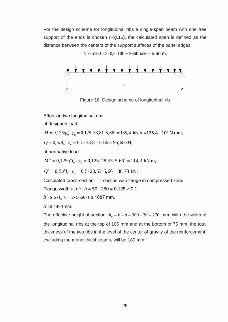
For the design scheme for longitudinal ribs a single-span beam with one free
support of the ends is chosen (Fig.16), the calculated span is defined as the
distance between the centers of the support surfaces of the panel edges.
56601005,0257600 =⋅⋅−=l мм = 5,66 m.
Figure 16. Design scheme of longitudinal rib
Efforts in two longitudinal ribs:
of designed load 2 20 n0,125 0,125 33,81 5,66 135,4M ql γ= ⋅ = ⋅ ⋅ = kN⋅m=135,4 ⋅ 106 N⋅mm;
00,5 0,5 33,81 5,66 95,68nQ ql γ= ⋅ = ⋅ ⋅ = kN;
of normative load 2 200,125 0,125 28,53 5,66 114,3n n
nM q l γ= ⋅ = ⋅ ⋅ = kN⋅m;
00,5 0,5 28,53 5,66 80,73n nnQ q l γ= ⋅ = ⋅ ⋅ = kN;
Calculated cross-section – T-section with flange in compressed zone.
Flange width at h′f : h = 50 : 250 = 0,125 > 0,1
b´f ≤ 6/5660262 0 ⋅=⋅ l ≤ 1887 mm.
b´f ≤ 1490mm.
The effective height of section: 270303000 =−=−= ahh mm. With the width of
the longitudinal ribs at the top of 105 mm and at the bottom of 75 mm, the total
thickness of the two ribs in the level of the center of gravity of the reinforcement,
excluding the monolithical seams, will be 180 mm.

26
Calculation of the strength of normal cross-sections.
The work of concrete in the monolithical seams into the safety margin is not
taken into account, assuming that, under unfavorable conditions, reliable joint
work of the concrete with the longitudinal ribs due to their adhesion may not be
ensured. Then the calculated width of the flange:
1460301490 =−=′fb mm.
The calculation is made on the assumption that the compressed reinforcement
is not required by calculation, sA′ = 0:
( ) ( ) 60 101,236505,02705014602,135,0 ⋅=⋅−⋅⋅=′−′′ fffb hhhbR N⋅mm = 236,1 kN⋅m > М =
135,4 kN⋅m
This means that the neutral axis passes within the flange (х<h′f) and the
element is calculated as a rectangular with a width b′f = 1460 мм.
The required amount of prestressed reinforcement of А600 class at 6
2135,4 10 0,1
13,2 1460 270mα⋅
= =⋅ ⋅
<αR = 0,34,
)5,.01( RRR ξξα ⋅−⋅= , where Rξ is accepted at the ratio 6,0=s
sp
Rσ
.
43,0=Rξ (for this calculation), 34,0)43,05,01(43,0 =⋅−=Rα
Hence compressed reinforcement is not required by calculation.
ssmfbsp RhbRA 30 /)211( γα−−′′= mm2,
3
1 1 2 1 1 2 0,11,25 0,25 1 0,25 1,25 0,25 1,190,43 0,43
ms
R
αξγξ
− − − − ⋅= − = − ⋅ = − ⋅ =
Condition: 1,13 ≤sγ
13,2 1460 270 (1 1 2 0,1) / (1,1 680) 806,55sрA = ⋅ ⋅ ⋅ − − ⋅ ⋅ =
Bar reinforcement of 4 roads is accepted 4∅18 А600 с Аsf = 1018 mm2 > 806,55
mm2.
A240 reinforcement with a diameter of 10 mm is chosen for mounting
reinforcement of longitudinal ribs in form of flat welded frames with
A's = 78,5 · 2=157 mm2 = 0,00016 m2.

27
Calculation of the strength of inclined sections.
For structural reasons, we adopt a transverse reinforcement of class A240 with
Rsw = 170 МПа. In two flat welded frames, the transverse rods according to the
conditions of the welding technology are taken equal to 6 mm in diameter.
The maximum permissible distance between rods of the transverse
reinforcement at the supports at h0 = 300–30 mm = 270 mm: s ≤ 0,5h0 = 0,5 ·
270 = 135 mm; s ≤ 300 mm.
The distance between the rods is taken equal to s = 100 mm on the length
section near the support (1/4 span distance) и 200 mm (0,75 h0 = 0,75·0,27 =
202,5 mm) in the middle.
Calculation of the strength of the strip between inclined sections.
The width of the 2 ribs in the middle of cross-section 18,02,0 =⋅=b m.
Q ≤ 0,3Rbbh0 , where Q is taken at the distance from the support not less than
h0; 0,3 Rbbh0 = 0,3 · 13,2 · 103 · 0,18 · 0,27 = 192,5 kN >
> Q = Q – qh0 = 95,68 – 33,81 · 0,27 = 86,55 kN, hence strength of strip
between inclined sections is guaranteed.
Calculation of the inclined section under a shear force effect (7).
The calculation of the bent elements in an in is made from the condition:
swb QQQ +≤
where Q is the shear force from the vertical external load applied to the upper
edge of the element.
The transverse force carried by concrete is determined by the formula
c
MQ bb =
but, no more than Qb,max = 2,5Rbtbh0 and not less than Qb,min = 0,5 nϕ Rbtbh0
Mb =1,5 nϕ Rbtbh02 , с - projection of the unfavorable inclined section.
075,0 cqQ swsw =

28
To take into account the positive effect of prestress on the load-bearing capacity
of concrete in transverse force (coefficicient nϕ ) it is necessary to determine
the value of the pre-compression force P taking into account the loss of
prestressing in the reinforcement.
Determination of geometric characteristics of the cross-section.
sA and sA′ in the calculations of the characteristics of the reduced section, we
do not take into account conditionally.
Coefficient of reduction 63,71075,2
101,24
5
=⋅⋅
==b
s
EE
α
Concrete area:
A = b´f . h´f +2. Аr= 1460∙50+2∙300∙90=127000 mm2
Reduced section area:
Ared = A + αAsp = 127000 + 7,63∙1018 = 134767,3 mm2.
The static moment relative to the bottom edge of the longitudinal ribs:
( )1460 50 300 0,5 50 180 250 250 / 2
37,63 1018 30 25933020
S A y Si spred bi
mm
α= ⋅ + = ⋅ ⋅ − ⋅ + ⋅ ⋅ +∑
+ ⋅ ⋅ =
The distance from the most stretched concrete fiber to the center of gravity of
the reduced section:
y = Sred / Ared = 25933020 / 134767,3 = 192,4 mm.
The moment of inertia of reduced section relative to the center of gravity:
( ) ( ) ( ) ( )
( ) ( ) ( )
( ) ( ) ( )
3322
332 2
2 2 4
0,5 0,512 12
180 300 501460 50 1460 50 300 192,4 0,5 5012 12
180 300 50 192,4 0,5 300 50 7,63 1018 192,4 30 1156922974
1,
ff fred f f f f f
sp
b h hb hJ b h h y h b h h y h h
A y a
mm
α
′−′ ′⋅ ′ ′ ′ ′ ′= + ⋅ − − ⋅ + + − ⋅ − − +
⋅ −⋅+ ⋅ − = + ⋅ − − ⋅ + +
+ ⋅ − ⋅ − − + ⋅ ⋅ − = = = 9 416 10 mm⋅
The moment of resistance of the reduced section:
W = Jred/y = 1,16 . 109 / 192,4 = 6,02 . 106 mm3.
We take into account the inelastic deformations of the stretched concrete by
multiplying W by the coefficient γ = 1.3,
Wpl = 6,02 . 106 . 1,3 = 7,84 . 106 mm3.

29
Determination of prestressing value taking into account losses spσ .
The initial value of prestressing of the reinforcement is:
785 93,6 586,4sp snR p MPaσ ≤ − = − = 02 =∆ spσ ;
The initial value of prestressing is taken equal to 450 MPa
First loses:
а) From stress relaxation in the reinforcement under the electrothermal method
of tension
1 0,03 0,03 450,0 13,5sp spσ σ∆ = = ⋅ = MPa;
b) From temperature drop
2 0spσ∆ = ;
c) From form deformation
03 =∆ spσ ;
d) From anchors deformation
04 =∆ spσ ;
The sum of the first losses
( ) 5,131 =∆ spσ MPa.
Compression force taking into account the first losses:
( ) ( ) ( ) 35,4445,130,4501018)1(1 =−=∆−= spspspAP σσ kN.
Since in the upper zone there is no tensional reinforcement ( 0' =spA ), then
4,162304,19210 =−=−== spspp ayye mm.
The maximum compressive stress in the concrete aе the lower edge of the rib
from the action ( )1Р at the moment of its own weight 0=М , yys = , is equal to
( ) ( )6 6
0 11 16 9
0, 444 10 0,444 10 162,4 192,4 3,13 11,960,134 10 1,16 10
15,27
pbp
red red
P P e yA J
MPa
σ⋅ ⋅ ⋅ ⋅ ⋅
= + = + = + =⋅ ⋅
=
15,27 MPa 65,165,189,09,0 =⋅=< bpR MPa.
The strength of concrete is sufficient to perceive the compression force.
Second losses:

30
а) From shrinkage of concrete В25
42101,20002,0 5,5 =⋅⋅=⋅=∆ sshbsp Eεσ MPa;
where εb,sh - is the shrinkage deformation of concrete, taken equal to:
0,0002 - for concrete of classes B35 and below;
b) From concrete creep
( )crbred
redsppsp
bpcrbsp
JAye
,10
,6
8,0111
8,0
ϕαµ
σαϕσ
+
±+
⋅⋅=∆ .
For concrete of class B25
crb,ϕ = 2,5; Еb = 27500 MPa; .63,7105,27
101.23
5
=⋅⋅
==b
s
EEα
Calculation of the bending moment in the middle of the span of the slab from its
own weight: 2 2
2 0 5,46 5,66 23,068 8
nb
g lM γ ⋅= = = kN⋅m.
The stress in the concrete in the level of the center of gravity of the prestressed
reinforcement from the compression force taking into account the bending
moment from the plate's own weight:
( ) ( )
6 60 11 1
6 9
6
9
0, 444 10 0,444 10 162,4 192,40,134 10 1,16 10
23,06 10 192,4 3,13 11,96 3,82 11,271,16 10
p sp spbp
red red red
P P e y M yA J J
MPa
σ⋅ ⋅ ⋅ ⋅ ⋅ ⋅
= + − = + −⋅ ⋅
⋅ ⋅− = + − =
⋅
11,27 MPa 65,165,189,09,0 =⋅=< bpR MPa. Stress in concrete in the level of the center of gravity of the upper non-
tensioning reinforcement
( ) 6,774,19230300' =+−=−′−= yahy ss mm;

31
The distance between the centers of gravity of the prestressed reinforcement
and the reduced cross section
4,16210 == psp ey mm. Reinforcement ratio
008,0127000
1018===
AAsp
spµ , .001,0127000
157==
′=′
AAs
sµ
( )6 6
9
0,8 2,5 7,63 15,27 126,3162,4 192,4 0,134 101 7,63 0,008 1 1 0,8 2.5
1,16 10
sp MPaσ ⋅ ⋅ ⋅∆ = =
⋅ ⋅ ⋅+ ⋅ + + ⋅ ⋅
( )6 6
9
0,8 2,5 7,63 0,03 0,4239,04 274,04 0,157 101 7,63 0,001 1 1 0,8 2.8
3,17 10
sp MPaσ ⋅ ⋅ ⋅′∆ = = ⋅ ⋅ ⋅
+ ⋅ + + ⋅ ⋅
6 0sp MPaσ ′∆ ≅ Total second losses:
)2(spσ∆ = 5spσ∆ + 6spσ∆ = 42 + 126,3 = 168,3 MPa.
Total loss of prestression: ( ) ( ) =σ∆+σ∆ 21 spsp 13,5 + 168,3 = 181,8 MPa > 100 MPa.
Stress 2spσ with all losses:
2spσ = 450 – 181,8 = 268,2 MPa. The compression force taking into account all stress losses P is determined
when the stresses in the non-tensioning reinforcement are equal to sσ .
sσ conditionally assumed to be equal to the second losses, i.e.
sσ = )2(spσ∆ =168,3 MPa
6,2461573,16810182,2682 =⋅−⋅=−= ssspsp AAP σσ kN.
Qb,min = 0,5 nϕ Rbtbh0 = 0,5 ·1,41·0,95·103 · 0,18 · 0,27 = 32,5 kN
Qb,max= 2,5 Rbtbh0 = 2,5 · 0,95 · 103 · 0,18 · 0,27 = 115,42 kN.
( )6 6 6
1 1 0 1' '6 9
0, 444 10 0,444 10 162,4 23,06 10 77,60,134 10 1,16 10
3,31 3,28 0,03
bp
p bs
red red
P Pe My
A JMPa
σ− ⋅ ⋅ ⋅ − ⋅
= − = − ⋅ =⋅ ⋅
− =

32
Value of the nϕ :
;41,11803005,13
106,24616,11803005,13
106,2466,1116,16,112332
11
=
⋅⋅
⋅⋅−
⋅⋅⋅
⋅+=
−+=
ARP
ARP
bbnϕ
Since the value 9,961,000005710170 3
1 =⋅⋅
==w
swswsw S
ARq >
2,6018,01095,041,125,025,0 3 =⋅⋅⋅⋅=> bRbtnϕ N/mm,
it is necessary to calculate stirrups fully.
Determination of the length of the projection of the unfavorable incline section c.
82,003,39
27,018,01095,041,15,15,1 2320 =
⋅⋅⋅⋅⋅===
qbhR
qMc btnb ϕ m, but no more
than 3h0 = 3 · 0,27 = 0,81 m.
The projection length of the unfavorable incline section is taken equal to c =
0,81 m.
The projection length of the inclined crack c0 is taken equal to c, but no more
than 2h0 = 2 · 0,27 = 0,54 m.
The length of the inclined crack is c0 = 0,54 m.
Then
25,3954,09,9675,075,0 0 =⋅⋅== cqQ swsw kN.
Q = qcQ − = 95,68 – 33,81 · 0,81 = 68,3 kN.
With the sum of the shear capacities Qsw + Qb,min = 39,25 + 32,5 = 71,75 kN >
Q = 68,3 kN, strength is ensured.
3.4 Longitudinal ribs calculation according to SLS
Determination of the crack width, normal to the longitudinal axis of the element. The reduced moment of resistance along the stretched edge of the longitudinal
ribs:
69
1003,64,192
1016,1⋅=
⋅==
yJ
W redred mm3.
Distance to the core point:
74,44134767
1003,6 6
=⋅
==red
red
AWr mm.

33
The moment of crack formation: +⋅⋅⋅=++= 85,11003,63,1)( 6
0, rePRWM pserbtredcrc γ ( ) 66 103,19074,444,16210246,0 ⋅=+⋅+ N⋅mm.
The values of predred eAyJP 0 , , , , are presented above
Coefficient 3,1=γ , Bending moment from normative load:
114,3nM = kN⋅m;
Consequently, cracks are formed.
1 2 3 ,s
crc s s crc ults
a l aEσϕ ϕ ϕψ= ≤
1ϕ = 1,4 with a continuous action of the load
2ϕ = 0,5 for a reinforcement of the periodic profile
3ϕ = 1 for bent elements
ssp
M P zA z
σ − ⋅=
⋅
z = 0,7h0 ls - base length between cracks
0,5 bts s
sp
Al dA
= ⋅ ⋅ ; ( )bt f f t fA h b y h b= ⋅ + − ⋅ ; 0ty k y= ⋅
0
,
red
redbt ser
Sy PAR
=+
; k =0,95;
025933 6,154441347
0,155
y cm= =+
0.95 6,15 5,84 2 6ty cm a cm= ⋅ = < = , yt = 6 cm 25 149 (6 5) 18 763btA cm= ⋅ + − ⋅ =
7630,5 1,8 67,510,18sl cm= ⋅ ⋅ =
ls need to be no more than 40 cm. 211430 440 18,9 16,18 / 161,8
10,18 18,9s kN cm MPaσ − ⋅= = =
⋅
,4
161,81,4 0,5 1,0 1,0 400 0,22 0,421 10crc crc ulta mm a mm= ⋅ ⋅ ⋅ ⋅ = < =⋅
Hence, the crack width is smaller than the ultimate width.
34
Deformation calculation.
Determination of curvature in the middle of the span from the action of
permanent and long-term loads, since the deflection is limited to aesthetic
requirements. 3
, 7 2, 4
,
18,5 10 0,66 10 /28 10
b serb red
b red
RE kN m
ε −
⋅= = = ⋅
⋅
For reinforcement in tensioned zone: 7
2 7,
21 10 31,81,0 0,66 10
ss
s b red
EE
αψ
⋅= = =
⋅ ⋅ ⋅
2 20
1018 31,8 0,66180 270
sps s
Abh
µα α= = =⋅
0
( ` ) ` (1490 180) 50 1,34180 270
f ff
b b hbh
ϕ− − ⋅
= = =⋅
0 107,6 162,4 30 240sp вe у e a mm= − − = + − = ;
where ув - distance from the center of gravity to the upper edge.
0
240 0,88270
speh
= =
0,88cφ =
Curvature of element:
-13 3 7
3 0 ,
1 1 114,3 0,0055 m0,88 0,18 0,27 0,66 10c b red
Mr r b h Eφ
= = = = ⋅ ⋅ ⋅ ⋅ ⋅ ⋅ ⋅
Curvature from prestressing:
5 6sb sp spσ σ σ= ∆ + ∆
5 6` `sb sp spσ σ σ= ∆ + ∆
-17
4 0
1 168,3 0,4 0,000003 m0,270 21 10
sb sb
sr h Eσ σ ′− − = = = ⋅ ⋅ ⋅
1
max 3 4
1 1 1 0,0055 0,000003 0,0055mr r r
− = − = − =
2 2
max
1 5 5,660 0,0055 0,01848
f S lr
= ⋅ = ⋅ ⋅ =
m.
fult = l/200 = 28 mm > 18,0 mm, calculation for the SLS is completed.

35
4 CALCULATION OF FIBER REINFORCED CONCRETE SLAB
Figure 17. Cross-section of slab.
Given: Slab dimensions 5760 ⋅2980, evenly distributed load q = 7,3 kN/m2,
Concrete B25 ( Rb = 13,2 MPa, Rbt = 0,95 MPa ), Rs = 680 MPa - for
prestressed reinforcement. Tension type - electrothermal tension. The diameter
of steel fiber = 0,8 mm, length of steel fiber = 80 mm, Rf = 500 MPa,
Rf,n = 600 MPa, µfv = 0,008, As = 254,5 mm2 (for 1 longitudinal rib).
Es = 2.1 ⋅105 MPa, Eb = 2.75 ⋅104 MPa.
Static calculation.
Table 4. Load determination for fiber reinforced slab longitudinal rib.
№ Type of load Normative load, kN/m2
Load safety factor
Designed load, kN/m2
Dead load
1 Cement floor weight δ=20
mm, ρ = 2000 kg/m3 0,4 1,3 0,52
2
Weight of concrete slab (self
weight) δ=20mm, ρ =2500
kg/m3 0,5 1,1 0,55
3
Transverse ribs* (5 pieces) b= = 75,0 mm
h = 200-20 = 170 mm ; ρ = 2500 kg/m3
0,25
1,1
0,28
4
Longitudinal ribs** (2 pieces) b= 90 mm; h = 300-20 =
270mm ρ = 2500 kg/m3
0,36
1,1
0,39
Total 1,51 1,74 Temporary load
5 Evenly distiributed load 7.3 1,2 8,76

36
Total 8,81 10,5
Total load on longitudinal rib:
Total designed load:
q∙bn = 10,5 ∙ 1,49= 19,4 kN/m,
Total normative load (for SLS):
(g+ν)bn = 8,81 ∙ 1,49= 13,13 kN/m,
4.1 Calculation of the reduced cross section of the fiber reinforced concrete
In view of the symmetry of the cross section, the calculation is carried out for
the half of the cross section of the slab.
Determination of the geometric characteristics of the reduced cross section:
Coefficients of reduction: 5
, 4
2,1 10 7,632,75 10
ss f
b
EE
α ⋅= = =
⋅
Reduced cross section area: red fa f s sA A A Aµ α α= + +
faµ - coefficient of the fiber reinforcement.
2fa or fvkµ µ= , where 2
ork is coefficient taken from “Guidlines for designing fiber
reinforced structures table 4”
Coefficient for the web: 20,676 0,008 0,0036fawµ = ⋅ =
Coefficient for the flange: 20,634 0,008 0,0032fafµ = ⋅ =
Since the values differ slightly, the average meaning is applied 0,0034faµ =
2
2
(1490 20 80 270 15 90 15 0,5)
(1 7,63 0,0034) (255 7,63) 56560red
mm
A = ⋅ + ⋅ + ⋅ + ⋅ ⋅
⋅ + ⋅ + ⋅ =
2)
2 23
(1 (1490 20 280 60 270 0,5
45 270 0,5 270 15 90 90 0,5 15
312031000
0,5 95)(1 7,63 0,0034) 7,63 255,5
f fared spS S S
mm
µα α= + + = ⋅ ⋅ + ⋅ ⋅ +
+ ⋅ ⋅ ⋅ ⋅ + ⋅ ⋅ ⋅ +
=
⋅ ⋅ ⋅
⋅ + ⋅ + ⋅ =
Distance from the center of gravity to the bottom edge:

37
312031 10 21356560
redcw
red
Sy mm
A⋅
= = =
213 30 183w cwy y a mm= − = − =
Calculation of the moment of the inertia of the reduced cross section. 3
2)
3 32
3 22 2
3 4 4
(1 (1490 20 1490 20 (280 213)12
60 270 270 45 270 45 27060 270 (213 )12 2 36 2
2 1515 15 1(213 270) (213 15 90 )3 36 2 3
(1 7,63 0,0034) 7,63 255 183 46666 10
f fared s sJ J J
mm
µα α= + + = ⋅ + ⋅ ⋅ − +
⋅ ⋅ ⋅+ + ⋅ ⋅ − + + ⋅
⋅⋅ − ⋅ + ⋅ ⋅ − ⋅ − ⋅
⋅ + ⋅ + ⋅ ⋅ = ⋅
Determination of strength properties of fiber reinforced concrete.
Fibreconcrete destruction can occur in two cases: all fibers are pulled out of
concrete, or part of the fiber is torn and the other part is pulled out of the
concrete matrix.
, 2f
f an
ll ≥ - first case of destruction,
, 2f
f an
ll < - second case of destruction.
,,
0,6 0,8 600 21,813,2
f f nf an
b
d Rl mm
Rη ⋅ ⋅ ⋅ ⋅
= = = , where η - is a coefficient that takes
into account profile of fiber (in case of fiber of periodic profile 0,6η = ).
Consequently, the destruction occurs in the second case.
Strength of fiber reinforced concrete in the second case:
,21( (1 ) (0,08 5,5 ))f an
fbt or fv f b fvf
R m kl
R Rl
µ µ= − + ⋅ − , where 1m - is a coefficient
that takes into account the presence of the anchors (in this case there are no
anchors 1m = 1).
Design tensile strength of the fiber reinforced concrete:

38
in rib: 20,676 21,80,008 500 (1 ) 0,48 2,180fbtR MPa= ⋅ ⋅ ⋅ − + = ,
in flange: 20,634 21,80,008 500 (1 ) 0,48 1,980fbtR MPa= ⋅ ⋅ ⋅ − + =
Design compressive strength of the fiber reinforced concrete: 2( )fb b n f fv fR R k Rϕ µ= + ⋅ ⋅ ⋅ , where nk - is a coefficient that takes into account
the work of the fibers in a section that perpendicular to the direction of the
external compressive force. The coefficient depends on the ratio of the length
and width of the section. In this case for rib 0,513nk = , for flange 0,634nk = .
fϕ - is a coefficient of efficiency of indirect reinforcement. 51 4,5f
LL
ϕ +=+
,
where n fv f
b
k RL
Rµ⋅ ⋅
= .
for rib: 20,513 0,008 500 0,07913,2
L ⋅ ⋅= = ; 5 0,079 3,7481 4,5 0,079fϕ += =+ ⋅
;
for flange: 20,634 0,008 500 0,11313,2
L ⋅ ⋅= = ; 5 0,113 3,391 4,5113fϕ += =+ ⋅
.
213,2 0,513 3,748 0,008 500 17,1( )fbwR MPa= + ⋅ ⋅ ⋅ = ;
213,2 0,634 3,39 0,008 500 18,7( )fbfR MPa= + ⋅ ⋅ ⋅ = .
Determintation of prestressing value taking into account prestression loses spσ .
The initial value of prestressing of the reinforcement is:
,0,3 225,5 93,6 450 785 93,6s ser sp snR p R pσ+ < ≤ − = + < < − ;
Initial value of prestressing is taken equal to 450 MPa
First loses:
From stress relaxation in the reinforcement under the electrothermal method of
tension
1 0,03 0,03 450,0 13,5sp spσ σ∆ = = ⋅ = MPa;
Compression force taking into account the first losses:
( ) ( ) ( )(1)1 255 450,0 13,5 111,31sp sp spP A kNσ σ= −∆ = − =
0 1 213 30 183p sp cwe y y a= = − = − = mm.

39
The maximum compressive stress in the concrete aе the lower edge of the rib
from the action ( )1Р at the moment of its own weight 0=М , yys = , is equal to
( ) ( )6 6
0 11 16 9
0,111 10 0,111 10 183 213 11,650,056 10 0,466 10
pbp
red red
P P e yMPa
A Jσ
⋅ ⋅ ⋅ ⋅ ⋅= + = + =
⋅ ⋅
11,65 MPa 0,9 0,9 18,5 16,65bpR< = ⋅ = MPa.
The strength of concrete is sufficient to perceive the compression force.
Calculation of the bending moment in the middle of the span of the slab from its
own weight: 2 2
2 0 1,74 5,66 11,428 8
nb
g lM γ ⋅= = = kN⋅m.
The stress in the concrete in the level of the center of gravity of the prestressed
reinforcement from the compression force taking into account the bending
moment from the plate's own weight:
( ) ( )
6 60 11 1
6 9
6
9
0,111 10 0,11 10 183 213`0,056 10 0,46 10
11,42 10 213 10,660,46 10
p sp spbp
red red red
P P e y M yA J J
MPa
σ⋅ ⋅ ⋅ ⋅ ⋅ ⋅
= + − = + −⋅ ⋅
⋅ ⋅− =
⋅
10,66 MPa 65,165,189,09,0 =⋅=< bpR MPa. Stress in concrete, taking into account the first losses:
1 450 13,5 10,66 425,84sp MPaσ = − − = .
Compressing force, taking into account the first losses:
1 425,84 255 108,65sp spP A kNσ= = ⋅ =
Second losses:
а) From shrinkage of concrete В25
42101,20002,0 5,5 =⋅⋅=⋅=∆ sshbsp Eεσ MPa;
where εb,sh - is the shrinkage deformation of concrete, taken equal to:
0,0002 - for concrete of classes B35 and below;
b) From concrete creep:

40
( )crbred
redsppsp
bpcrbsp
JAye
,10
,6
8,0111
8,0
ϕαµ
σαϕσ
+
±+
⋅⋅=∆ .
For concrete of class B25
crb,ϕ = 2,5; Еb = 27500 MPa; .63,7105,27
101.23
5
=⋅⋅
==b
s
EEα
The distance between the centers of gravity of the prestressed reinforcement
and the reduced cross section
0 1 183sp py e= = mm. Reinforcement ratio
255 0,00556560
spsp
AA
µ = = = ,
( )6 6
9
0,8 2,5 7,63 11,65 107,2183 213 0,056 101 7,63 0,005 1 1 0,8 2.5
0,46 10
sp MPaσ ⋅ ⋅ ⋅∆ = =
⋅ ⋅ ⋅+ ⋅ + + ⋅ ⋅
Total second losses:
)2(spσ∆ = 5spσ∆ + 6spσ∆ = 42 + 107,2 = 149,8 MPa.
Total loss of prestression: ( ) ( ) =σ∆+σ∆ 21 spsp 13,5 + 10,66 + 149,8 = 173,9 MPa > 100 MPa.
Stress 2spσ with all losses:
2spσ = 450 – 173,9 = 276,1 MPa. Compressing force, taking into account all losses:
02 2 276,1 255 70,405sp sp s sP A A kNσ σ= − = ⋅ = .
Calculation of strength of normal cross-sections.
Determination of the position of the boundary of the compressed zone.
, ,s s f btw wt f bf fR A R A R A⋅ + ⋅ ≤ ⋅ ;
680 255 2.1 23740 18,7 29800⋅ + ⋅ ≤ ⋅ ; 223254 557260< - The boundary of the
compressed zone passes through the flange, since the condition is satisfied.
Determination of the relative comrpession height:

41
, 680 255 2.1 23740 0,400` 18.7 1490 20
s s f btw wt
fb f
R A R Axh R b h
ξ⋅ + ⋅ ⋅ + ⋅
= = = =⋅ ⋅ ⋅ ⋅
Maximum value of the relative compression height:
,
1 (1 )1,1
rsr
sc u
ωξ σ ωσ
=+ ⋅ −
, where 0,8 0,008 0,8 0,008 13,2 0,695bRω = − ⋅ = − ⋅ = ,
and 2400 680 400 276,1 0,9 831,51sr s sp spRσ σ γ= + − ⋅ = + − ⋅ = ,
and ,sc uσ - maximum stress in compressed reinforcement equal to 400 MPa
0,695 0,613831,31 0,6951 (1 )400 1,1
rξ = =+ ⋅ −
; rξ ξ< - the compressed zone is within the
flange.
Strength condition: , 2 ( )2 2
w f ff btw w s s
h t tM R A R A h a
+≤ ⋅ ⋅ + ⋅ ⋅ − − .
2 20 n0,125 0,125 19,4 5,66 77,6M ql γ= ⋅ = ⋅ ⋅ = kN⋅m = 77,6 ⋅ 106 N⋅mm;
, 2 ( )2 2270 202,1 23700 680 2 255 (290 10 30) 93,916
2
w f ff btw w s s
h t tR A R A h a
kN m
+⋅ ⋅ + ⋅ ⋅ − − =
+= ⋅ ⋅ + ⋅ ⋅ ⋅ − − = ⋅
77,6 93,9< - strength is ensured.
Calculation of the strength of the concrete strip between inclined sections.
Strength condition: 1 10,3 w b bQ R hϕ ϕ= ⋅ ⋅ ⋅ ⋅ , where 1 1 5 fw fa
b
EE
ϕ µ= + ⋅ ⋅ , where
2 2 30,008 0,513 2,1 10fa fv nkµ µ −= ⋅ = ⋅ = ⋅ ; 4
31 4
2,1 101 5 2,1 10 1,080,27 10wϕ
−⋅= + ⋅ ⋅ ⋅ =
⋅;
1 1 0,01 1 0,01 13,2 0,868b bRϕ = − ⋅ = − ⋅ = .
0,3 1,08 0,868 13,2 270 60,3Q kN= ⋅ ⋅ ⋅ ⋅ =
00,5 0,5 19,4 5,66 54,9nQ ql γ= ⋅ ⋅ = ⋅ ⋅ = kN

42
54,9 60,3< - strength is ensured.
Calculation of the strength of inclined sections.
Strength condition: fb bQ Q Q≤ + , where ,0sin(90 )
f btw w wfb
R t hQ
β⋅
=−
;
For determination of tensile strength of it is necessary to change ork to
0,513nk = .
2, 0,513 21,80,008 500 (1 ) 0,48 1,5
80f btwR MPa= ⋅ ⋅ ⋅ − + = . Since application of load
is perpendicular to flange surface, angle 0β = .
,0
1,5 90 270 36450sin(90 ) 1
f btw w wfb
R t hQ N
β⋅ ⋅ ⋅
= = =−
;
2 2
0
0,75 0,75 0,95 90 290 19973sin(90 ) 270
bt wb
w
R t hQ Nh β
⋅ ⋅ ⋅ ⋅ ⋅ ⋅= = =
⋅ −
Condition check: fb bQ Q Q≤ + ;54,9 36,45 19,97 56,4kN≤ + = , hence strength
is ensured.
4.2 Longitudinal ribs calculation according to SLS
Determination of the crack width, normal to the longitudinal axis of the element.
Service limit state condition: crcM M≤ , where crcM - is a crack appearance
moment;
,crc bt ser pl rpM R W M= ⋅ + ;
moment of resistance of the fiber reinforced reduced cross section:
1 12 ( 1)bc f fc f ftpl bt
J J JW S
h xα α⋅ + ⋅ + ⋅ +
= +−
;
where bcJ , 1fcJ and 1ftJ - are moments of inertia of compressed concrete zone,
of fiber reinforcement area located at the compressed and tensioned zones
respectively.
Determination of the position of the neutral line (border between compressed
and tensioned areas):

43
1 1( )
2bt
bc f fc f fth x AS S Sα α − ⋅
+ ⋅ − ⋅ = , where x - is a coordinate of neutral line in
Y axis. Firstly it is necessary to determine coefficient of fibre reinforcement by
area , 21,81 0,5 1 0,5 0,86480
f anan
f
lk
l= − = − = .
2 2, 0,008 0,634 0,864 0,0028faf fvf or f ank kµ µ= ⋅ ⋅ = ⋅ ⋅ = ,
2 2, 0,008 0,676 0,864 0,0031faw fvw or w ank kµ µ= ⋅ ⋅ = ⋅ ⋅ = .
Value of x - is determined by equation:
2 2
( 0,5 ) (1 ) ( ) ( ) (1 )2
( ) ( )2 4
ff f f f faf w f f faw
f w w
x tb t h t b x t h
h x h xb b
α µ α µ
α
+⋅ ⋅ − ⋅ ⋅ + ⋅ + ⋅ − ⋅ − ⋅ + ⋅ −
− −− ⋅ ⋅ = ⋅
150x mm= .
3 32 2
32 4 3
2 1490 20 80 130( 1490 20 140 ) (1 7,63 0,0031) ( 80 130 65 )140 12 12
80 140(1 7,63 0,0028) (7,63 0,0028) ( 80 140 70 ) 80 140 70 1706,44 1012
plW
mm
⋅ ⋅= ⋅ + ⋅ ⋅ ⋅ + ⋅ + + ⋅ ⋅ ⋅
⋅⋅ + ⋅ + ⋅ ⋅ + ⋅ ⋅ + ⋅ ⋅ = ⋅
2 20 n0,125 0,125 13,3 5,66 53,26n nM q l kN mγ= ⋅ = ⋅ ⋅ = ⋅
02 ( )rp opM P e r= ⋅ ⋅ ; where red red
red cw red
W JrA y A
ϕ ϕ= ⋅ = ⋅⋅
;
where ,
1,6 1,6 0,75 0,85b
b serRσϕ = − = − =
40,85 46666 10 33213 56560
r mm⋅ ⋅= =
⋅, condition checking: crcM M≤ ;
453,26 1,85 1706,44 10 70405 (183 33) 46,77 kN> ⋅ ⋅ + ⋅ + = , condition is not
satisfied, hence cracks appears.
31 1 ,20 (3,5 )f
crc f red red red crc ultf
a d aEσ
δ ϕ η η µ= ⋅ ⋅ ⋅ ⋅ ⋅ ⋅ − ⋅ ≤ ; where 1δ = , 1 1,75ϕ = ;
10,5
0,5f mη =
+; 2 2
22
1 1 0,3640 ( 5 ) 40 0,8 (0,0034 5 0,006) 11 0,0034 42062
f fa s
fa
md
Aµ µ
µ
= = =⋅ ⋅ + ⋅ ⋅ ⋅ + ⋅
++⋅⋅
;
where A is an area of cross section.

44
2 1 0,0034 1 0,006 10,0034 0,006
f fa s sred
fa s
η µ η µη
µ µ⋅ + ⋅ ⋅ + ⋅
= = =+ +
; 0,0034 0,006 0,0094red fa sµ µ µ= + = + =
2 2 2 20,8 0,0034 0,8 0,006 17,50,8 0,0034 0,8 0,006
fa sred
fa s
d dd mm
d dµ µµ µ⋅ + ⋅ ⋅ + ⋅
= = =⋅ + ⋅ ⋅ + ⋅
Stress fσ is determined with accordance to SP 96.13330.2016 by formula 6.60
1
( )opf
f
M P e rW
σ− ⋅ +
= ; where 1f
fc
JW
y= ; fJ - is a moment of inertia of cross
section reduced to steel, including in it steel fibers area, area of bar
reinforcement, and areas of tensioned and compressed zones of concrete. 3
2
3 3 32
4 4
( ) ( ) ( )( ) ( )
12 2 12( ) ( ) ( )
( ) ( )2 12 2
8647,4 10 ;
f f faf f w faw ff f f faf
w f w faw w fawfaw s
b h h b x hJ b h x
b x h b h x b h xA h x a
mm
α µ α µα µ
µ µα µ α
⋅ ⋅ + ⋅ + ⋅ −= + ⋅ ⋅ + ⋅ − + +
⋅ − ⋅ − ⋅ ⋅ −+ ⋅ + + + + ⋅ ⋅ − − =
= ⋅
024
( ) (53260000 70405 (183 33)) 140 61,68647,4 10
op cf
f
M P e r yMPa
Jσ
− ⋅ + ⋅ − ⋅ + ⋅= = =
⋅
35
61,61 1,75 0,36 1 20 (3,5 0,0094) 17,5 0,0342,1 10crca mm= ⋅ ⋅ ⋅ ⋅ ⋅ ⋅ − ⋅ =
⋅; , 0,05crc ulta mm=
Deformation calculation.
max 5 6 7 4
1 1 1 1 1r r r r r
= − + −
, where 5 1 3
1 crc crc
f f
M M Mr B B
− = +
; 1fB - short-time
rigidity. 1 0,85f b bB E J= ⋅ ⋅ , where bJ - moment of inertia of cross section reduced
to concrete. 312031 10290 77
56484b
red
Sx h mmA A
⋅= − = − =
+;
3 3
23 3
2 2
2 4 4
1490 20 60 2701490 20 (77 10) (1 7,63 0,0031) 60 27012 12
245 270 (213 )45 270 15 15 15 13(213 0,5 270) (213 15 90)36 2 36 2 3
(1 7,63 0,0028) 7,63 255 183 46626 10 ;
bJ
mm
⋅ ⋅= + ⋅ ⋅ − ⋅ + ⋅ + + ⋅ ⋅
⋅ ⋅ −⋅ ⋅⋅ − ⋅ + + + + ⋅ − ⋅ − ⋅
⋅ + ⋅ + ⋅ ⋅ = ⋅

45
4 8 21 0,85 0,275 46626 10 108988 10fB N mm= ⋅ ⋅ ⋅ = ⋅ ⋅ ;
4 8 23 0,9 0,9 0,275 46626 10 115390 10f b bB E J N mm= ⋅ ⋅ = ⋅ ⋅ ⋅ = ⋅ ⋅ ;
4 8 23` 0,5 0,5 0,275 46626 10 64105 10f b bB E J N mm= ⋅ ⋅ = ⋅ ⋅ ⋅ = ⋅ ⋅ ;
7 75 1
8 85
1 4,66 10 (5,32 4,66) 10 0,48 10108988 10 115390 10
mmr
− −⋅ − ⋅ = + = ⋅ ⋅ ⋅ ;
75 1
86 3
1 5,33 10 0,46 10115390 10
n
f
M mmr B
− −⋅ = = = ⋅ ⋅ ;
75 1
87 3
1 5,33 10 0,83 10` 64105 10
n
f
M mmr B
− −⋅ = = = ⋅ ⋅ ;
5 1
4
1 149,8 0,245 102,1 10 290
b
s
mmr E h
σ − − = = = ⋅ ⋅ ⋅ ⋅ ;
5 1
max 5 6 7 4
1 1 1 1 1 0,605 10 mmr r r r r
− − = − + − = ⋅
2 2 5
max
1 5 5660 0,605 10 20 2848 ultf S l mm f mm
r− = ⋅ = ⋅ ⋅ ⋅ = < =
. SLS calculation
completed.
5 COMPARISON OF TWO TYPES OF SLAB
Table 5. Material consumption comparison.
Floor slab
Concrete, m3 Steel, kg
Steel
reinforced
sample
Fiber
reinforced
sample
Steel
reinforced
sample
Fiber
reinforced
sample
1,37 m3 0,916 m3 136,1 110,67
Table 6. Material cost and labor cost comparison.
Floor slab
Material cost, eur Labor cost, man-day
Steel
reinforced
sample
Fiber
reinforced
sample
Steel
reinforced
sample
Fiber
reinforced
sample
112 108 10,39 7,79

46
Fiber consumption per m3 of concrete = 57 kg. For these samples the combined
method of reinforcement was used. In fiber reinforced slab, longitudinal and
transverse reinforcement was left, vertical stirrups and reinforcement mesh in
flange were replaced by evenly distributed steel fibers. It has been proven by
experience that despite of the absence of a reinforcing mesh in the flange of the
plate, the monolithic connection of the shelf and ribs is saved. The total weight
of a normal reinforced slab is equal to 3560 kg, the weight of fiber reinforced is
equal to 2400 kg ( weight reduction was achieved by reducing the thickness of
the flange of the slab).
According to the researches of N.I. Vatin (9), other properties of reinforced
concrete in comparison with conventional reinforced concrete are presented
below. Economic comparison of slabs made according to F.N. Rabinovich
(2003, p-p. 338-350).
Table 7. Increasing of properties of fiber reinforced sample.
Property Increasing of property,%
Compressive strength 10-15
Tensile strength 100-150
Impact strength 500-900
Fire resistance 100-300
Abradability 30-40
Watertightness 50-100
Frost resistance 50-100
Durability 50-100
Increasing of strength properties is possible to reach if fiber reinforcement is
used with normal reinforcement jointly. It is possible to see on an example of
load-carrying structures such as slabs, beams, and etc. Increasing of service
properties (such as fire abradability, watertightness and etc.) is possible to
reach without normal reinforcement. For example as a top layer of coating of
industrial floors, coating of airfields andother abrasion-resistant surfaces.

47
Figure 18. Diagram of slabs comparison.
Figure 19. Diagram of slabs properties comparison.

48
6 CONCLUSION Nowadays, there are many variations of use of fiber reinforcement in the
construction industry. The required properties of concrete are possible to reach
with addition of different types of fibers. Fiber-reinforced concrete is a general
name of the structural material, because fibers differ strongly. One type of fiber
reinforced concrete (with addition of mineral fibers) can be used instead of
normal reinforced concrete for increasing specific properties of material.
Another one (with addition of steel fibers) can be used to increase the main
properties of an element (such as strength, deformations and crack formation).
On an example of different reinforced concrete slabs, the effectiveness
evaluation of fiber reinforcement application was carried out. The results of this
study show that it is possible to save about 10 percent of the total cost of the
element, which may become a huge figure in the construction of large objects.
Despite of the high efficiency of the application, the use of fiber reinforced
concrete is constrained by the value of applicated load, because fiber
reinforcement is chaotically oriented and can not fully replace rod
reinforcement.
The most effective application of fiber reinforced concrete is structures that
carry dynamic loads, that are exposed to frost and water.

49
Figures Figure 1. «Dramix» 80/60 anchoring fiber. p. 9
Figure 2. «Fibraprom» milled anchoring fiber. p. 10
Figure 3. «Rosfiber» wave fiber. p. 10
Figure 4. «Rosfiber» milled from the steel melt fiber. p. 11
Figure 5. «Fibraprom» basalt fiber. p. 12
Figure 6. «Fibraprom» nylon fiber. p. 13
Figure 7. «Fibraprom» glass fiber. p. 13
Figure 8. «Fibraprom» polypropelene fiber. p. 14
Figure 9. Example of concrete ribbed slab. p. 15
Figure 10. Section view of manufactory building. p. 15
Figure 11.General elements of concrete ribbed slab. p. 16
Figure 12. Cross-section of slab. p. 16
Figure 13. Calculated span determination. p. 17
Figure 14. Design scheme of slab flange. p. 19
Figure 15. Design scheme of intermediate rib. p. 21
Figure 16. Design scheme of longitudinal rib. p. 25
Figure 17. Cross-section of slab. p. 35
Figure 18. Diagram of slabs comparison. p. 47
Figure 19. Diagram of slabs properties comparison. p. 47
Tables Table 1. Types and properties of reinforcement fibers. p. 8
Table 2. Load determination for slab flange. p. 18
Table 3. Load determination for slab longitudinal rib. p. 24
Table 4. Load determination for fiber reinforced slab longitudinal rib. p. 35
Table 5. Material consumption comparison. p. 45
Table 6. Material cost and labor cost comparison. p. 45
Table 7. Increasing of properties of fiber reinforced sample. p. 46

50
REFERENCES 1. GOST 22701.0-77, «Prestressed reinforced concrete slabs».
2. Arnon Bentur, Sidney Mindess, Taylor & Francis. 2007. «Fibre reinforced
cementitious composites».
3. S.V. Kluev, «High-strength fiber-reinforced concrete for industrial and civil
construction». Magazine of Civil Engineering №8, 2012
4. F.N.Rabinovich, «Composite materials based on fiber reinforced concrete».
ACB, Moscow, 2004
5. NIIZhB, Russia. 2013. «Recommendations for the design and manufacturing
of steel-fiber-reinforced concrete structures».
6. SP 52-104-2006 «Steel fibre reinforced concrete structures».
7. SP 63.13330.2017 «Concrete structures».
8. SP 20.13330.2017 «Loads and actions».
9. N.I. Vatin, «Industrial floors with a layer of wear made of fiber concrete».
Stroyprofile magazine №7, 2006
10. «Fibraprom» official website https://fibraprom.ru/ . Assesed on 6 October
2017