comparison of e ects of various contaminations on sir
TRANSCRIPT

Comparison of effects of VariousContaminations on SiR insulators
Satheesh Gundlapalli1,B. Basavaraja2,Pradeep M. Nirgude3
1,2Department of E.E.,3UHV Research Laboratory
1S R Engineering CollegeWarangal, India.
2University B.D.T. College of EngineeringKarnataka, India .
3Central Power Research InstituteTelangana, India.
October 12, 2018
Abstract
The essential part of High Voltage (HV) power transmis-sion system is an insulator. Its unsatisfactory performancewill result in considerable loss of capital. The main aim ofthis paper is to compare the effect of pollution on flash overvoltage (FOV) of 11 KV straight and alternate shed sili-cone rubber (SiR) insulators under different scenarios. Thedifferent scenario conditions are clean condition and vari-ous contamination conditions. These scenarios are seen inthe field with in-service insulators located near industries.In the first case, two types of insulators were tested underclean condition and in the second case the insulator sam-ples were tested considering only cement dust along theirsurfaces. In the remaining cases the insulators were testedwith plywood dust, cement dust water drops, water drops
1
International Journal of Pure and Applied MathematicsVolume 120 No. 6 2018, 609-620ISSN: 1314-3395 (on-line version)url: http://www.acadpubl.eu/hub/Special Issue http://www.acadpubl.eu/hub/
609

only and plywood dust water drops. Above tests revealedthat in polluted environments alternate shed insulators havehigher flash over voltages compare to straight shed insula-tors. Hence in polluted environments alternate shed insula-tors are to be used compared to straight shed insulators. So,we can predict the scheduled maintenance or replacementof the SiR insulators under different environments.Key Words:: Breakdown voltage; Contamination; Insula-tor; Dust; Water
1 Introduction
Electrical insulators support the conductors and they must with-stand normal voltages, various operating conditions and environ-ments. Overhead line insulators are being subjected to variousoperating conditions and environments. So insulator surfaces werecovered by pollutants due to natural or industrial or even combi-nation of both. Contamination on the surface of the overhead lineinsulators enhances the chances of flashover [1]. The contaminationis little important in dry conditions because the contaminated sur-faces do not conduct under dry periods. Because of the presence ofionic solids the pollution layer becomes conductive as the insulatorsurface becomes moist because of rain, dew or fog [2]-[3]. The mostimportant problem in power transmission is flashover observed oninsulators used in HV power transmission [4]. On the other hand,the flashover of polluted insulators can cause transmission line out-age. The flashover of polluted insulators was the motivation for theinstallation of a test station in order to perform tests on pollutedinsulators [5]. The insulator begins to fail when the pollutants thatexist in the air settle on the surface of the insulator and combinewith the humidity of the rain, fog or dew. The mixture of pollu-tants and humidity form a layer that become conductor and allowspassage of currents that will facilitate the conditions of short circuit[6]-[7]. This is due to decrease of the resistance of insulator surface.Unless there is an adequate maintenance or natural cleaning, theelectrical activity will be affected by a flashover on the insulator.
2
International Journal of Pure and Applied Mathematics Special Issue
610
2 SIR INSULATOR
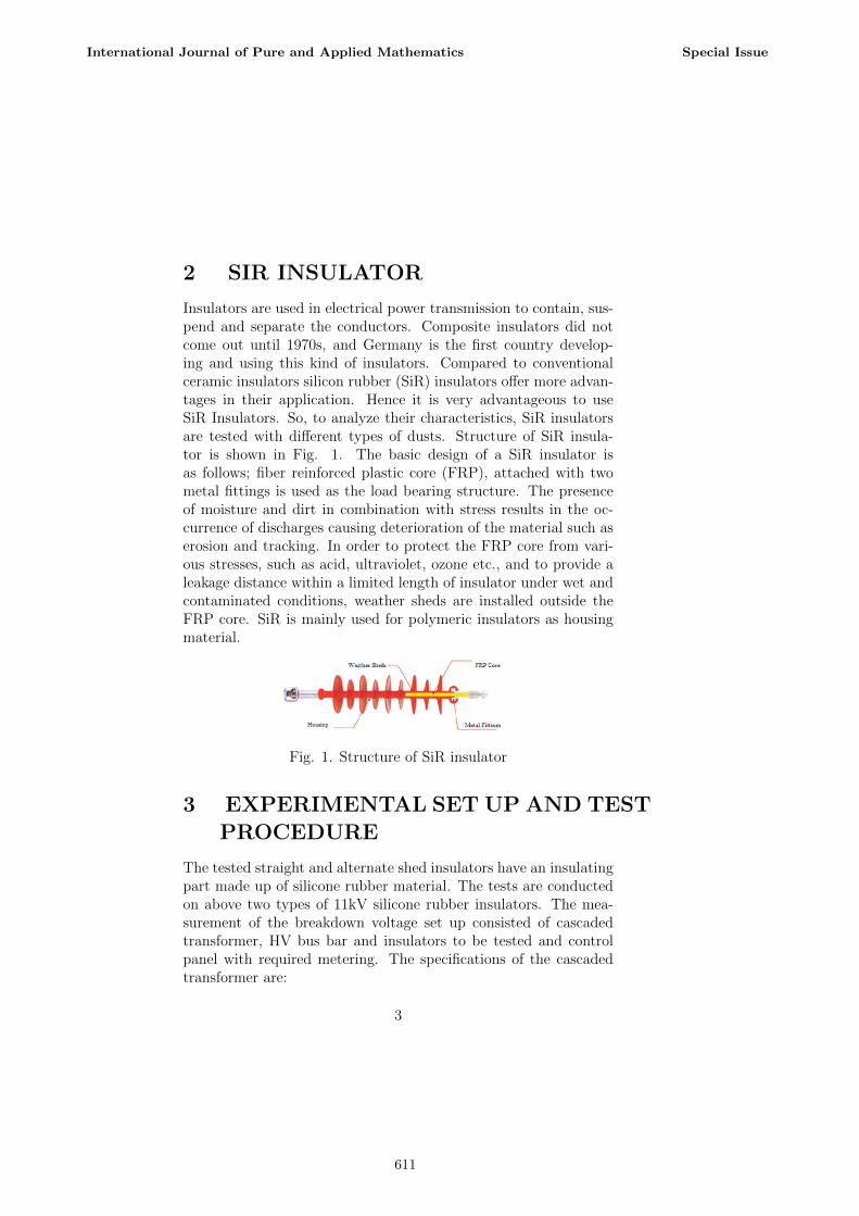
Insulators are used in electrical power transmission to contain, sus-pend and separate the conductors. Composite insulators did notcome out until 1970s, and Germany is the first country develop-ing and using this kind of insulators. Compared to conventionalceramic insulators silicon rubber (SiR) insulators offer more advan-tages in their application. Hence it is very advantageous to useSiR Insulators. So, to analyze their characteristics, SiR insulatorsare tested with different types of dusts. Structure of SiR insula-tor is shown in Fig. 1. The basic design of a SiR insulator isas follows; fiber reinforced plastic core (FRP), attached with twometal fittings is used as the load bearing structure. The presenceof moisture and dirt in combination with stress results in the oc-currence of discharges causing deterioration of the material such aserosion and tracking. In order to protect the FRP core from vari-ous stresses, such as acid, ultraviolet, ozone etc., and to provide aleakage distance within a limited length of insulator under wet andcontaminated conditions, weather sheds are installed outside theFRP core. SiR is mainly used for polymeric insulators as housingmaterial.
Fig. 1. Structure of SiR insulator
3 EXPERIMENTAL SET UP AND TEST
PROCEDURE
The tested straight and alternate shed insulators have an insulatingpart made up of silicone rubber material. The tests are conductedon above two types of 11kV silicone rubber insulators. The mea-surement of the breakdown voltage set up consisted of cascadedtransformer, HV bus bar and insulators to be tested and controlpanel with required metering. The specifications of the cascadedtransformer are:
3
International Journal of Pure and Applied Mathematics Special Issue
611
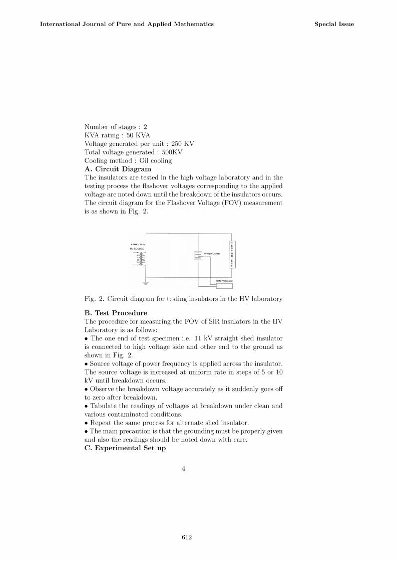
Number of stages : 2KVA rating : 50 KVAVoltage generated per unit : 250 KVTotal voltage generated : 500KVCooling method : Oil coolingA. Circuit DiagramThe insulators are tested in the high voltage laboratory and in thetesting process the flashover voltages corresponding to the appliedvoltage are noted down until the breakdown of the insulators occurs.The circuit diagram for the Flashover Voltage (FOV) measurementis as shown in Fig. 2.
Fig. 2. Circuit diagram for testing insulators in the HV laboratory
B. Test ProcedureThe procedure for measuring the FOV of SiR insulators in the HVLaboratory is as follows:• The one end of test specimen i.e. 11 kV straight shed insulatoris connected to high voltage side and other end to the ground asshown in Fig. 2.• Source voltage of power frequency is applied across the insulator.The source voltage is increased at uniform rate in steps of 5 or 10kV until breakdown occurs.• Observe the breakdown voltage accurately as it suddenly goes offto zero after breakdown.• Tabulate the readings of voltages at breakdown under clean andvarious contaminated conditions.• Repeat the same process for alternate shed insulator.• The main precaution is that the grounding must be properly givenand also the readings should be noted down with care.C. Experimental Set up
4
International Journal of Pure and Applied Mathematics Special Issue
612

After washing the insulator samples with water and kept dry for24 hours, they are placed in the experimental setup with a groundclearance of approximately two meter. One end of the insulatorwas connected to high voltage side and the other end to ground asshown in Fig. 3. The occurrence of flashover of 11 kV straight andalternate shed insulators is as shown in Fig. 4. They are energizedto measure the flashover voltages under clean and contaminatedconditions.
Fig. 3. (a) straight shed insulator
(b) alternate shed insulator
5
International Journal of Pure and Applied Mathematics Special Issue
613

Fig. 4. Flashover of (a) straight shed insulator
(b) alternate shed insulator
4 TEST RESULTS
A. Testing of Alternate shed type insulator under cleanand various polluted conditionsThe Alternate shed type insulator is tested without and with var-ious contaminations on its surface to study the variation of thebreakdown voltage. Following are the test results (flashover volt-ages) of insulator without and with various contaminations on itssurface.
TABLE I. FLASHOVER VOLTAGE UNDER VARIOUSCONTAMINATION CONDITIONS FOR 11KV ALTERNATE
6
International Journal of Pure and Applied Mathematics Special Issue
614

SHED INSULATOR
The plot drawn between flashover voltage and various dust condi-tions using Table I is shown in Fig. 5
Fig. 5. Flashover voltages of 11kV alternate shed insulator underclean and various contaminated conditions
From Fig. 5 it is observed that the flashover voltage of Alternateshed insulator is reduced by 2.35 % under cement dust comparedto clean condition, 5.88 % under plywood dust compared to cleancondition, 29.41 % under cement dust and water drops compared toclean condition, 31.76 % under water drops compared to clean con-dition and 36.47 % under plywood dust and water drops comparedto clean condition. Therefore flashover voltage is less for pollutedinsulator compared to unpolluted insulator.B. Testing of Straight shed type insulator under clean andvarious polluted conditionsThe straight shed type insulator is tested without and with variouscontaminations on its surface to study the variation of the break-down voltage. Following are the test results (flashover voltages) ofinsulator without and with various contaminations on its surface.
TABLE II. FLASHOVER VOLTAGE UNDER VARIOUS
7
International Journal of Pure and Applied Mathematics Special Issue
615

CONTAMINATION CONDITIONS FOR 11KV STRAIGHTSHED INSULATOR
Fig. 6. Flashover voltages of 11kV straight shed insulator underclean and various contaminated conditions
From Fig. 6 it is observed that the flashover voltage of Straightshed insulator is reduced by 2.63 % under cement dust comparedto clean condition, 6.58 % under plywood dust compared to cleancondition, 32.89 % under cement dust and water drops comparedto clean condition, 35.53 % under water drops compared to cleancondition and 44.74 % under plywood dust and water drops con-dition compared to clean condition. Therefore flashover voltage isless for polluted insulator compared to unpolluted insulator.C. Analysis of resultsA comparison is made between the flashover voltages of the twotypes of insulator samples under different contamination conditions.The plot drawn between flashover voltage and various dust condi-tions is shown in Fig. 7.
8
International Journal of Pure and Applied Mathematics Special Issue
616

Fig. 7. Comparison of flashover voltages of 11kV alternate andstraight shed insulators under clean and various contaminated
conditions
From the plot in Fig. 7 the flashover voltages of alternate shed in-sulator are higher than that of straight shed type insulators underdifferent polluted conditions.1. The flashover voltage of alternate shed insulator is 11.84 %higher than that of straight shed insulator under clean condition.2. The flashover voltage of alternate shed insulator is 12.16 % higherthan that of straight shed insulator under cement dust condition.3. The flashover voltage of alternate shed insulator is 12.68 % higherthan that of straight shed insulator under plywood dust condition.4. The flashover voltage of alternate shed insulator is 17.65 %higher than that of straight shed insulator under cement dust andwater drops condition.5. The flashover voltage of alternate shed insulator is 18.37 % higherthan that of straight shed insulator under water drops condition.6. The flashover voltage of alternate shed insulator is 28.57 %higher than that of straight shed insulator under plywood dust andwater drops condition.
5 Conclusion
The flashover voltage measurement is done on 11 kV alternate shedand straight shed insulators without and with contaminations. Thecontamination conditions considered are: (1) Clean condition, (2)Cement dust condition, (3) Plywood dust condition, (4) Cementdust and water drops condition, (5) Water drops condition, and (6)Plywood dust and water drops condition. The contamination con-ditions considered are similar to pollutions that exist on overheadline insulators in industrial areas. The flashover voltages in case
9
International Journal of Pure and Applied Mathematics Special Issue
617

of alternate shed insulators with and without pollution are higherthan straight shed insulators. Also flash over voltage is higher forpolluted insulator compared to unpolluted insulator. It is observedthat the flashover voltage in case of plywood dust water contami-nated condition is lower than that of the other conditions in bothtypes of insulators. Similarly, the flashover voltage is less for con-ditions containing water drops than the other conditions i.e. clean,cement dust and plywood dusts. This is because of the fact waterand water along with dusts has high conductivity value than theother conditions. From the above facts it is observed that the in-sulators are to be designed based on environment present aroundthe insulator. Also in polluted environments alternate shed insu-lators are to be used compared to straight shed insulators. Fromthe results obtained we can predict the schedule maintenance orreplacement of the insulators under different contamination condi-tions.
References
[1] M. T. Gencoglu and M. Cebeci, The pollution flashover onhigh voltage insulators, Electric power systems research, vol.78, no. 11, pp. 1914-1921, November 2008.
[2] V. Vinayaka Rao and D. Pradip kumar, Electric field com-putation of 400kv ac porcelain string insulator, InternationalJournal of Electrical Engineering Technology, vol. 3, no. 2, pp.174-181, July-September 2012.
[3] V. Jayaprakash Narayanan, M. Sivakumar, K. Karpagavaniand S. Chandrasekar, Prediction of Flashover and PollutionSeverity of High Voltage Transmission Line Insulators UsingWavelet Transform and Fuzzy C-Means Approach, Journal ofElectrical Engineering and Technology, vol. 9, no. 5, pp. 1677-1685, September 2014.
[4] S. A. Suflis, I. F. Gonos, F. V. Topalis and I. A. Stathop-ulos, Study of the dielectric behaviour of non-uniformly pol-luted insulators,” XIII th international symposium on Highvoltage engineering, School of Electrical and Computer Engi-neering, Electric Power Department, High Voltage Laboratory
10
International Journal of Pure and Applied Mathematics Special Issue
618

National Technical University of Athens, Greece, Netherlands,Smit (ed.), Rotterdam, pp. 1-4, 2003.
[5] M. A. M Piah and A. Darus, Modelling leakage current andelectric field behavior of wet contaminated insulators, IEEETransactions on power delivery, vol. 19, no. 1, pp. 432-433,2004.
[6] P. Jirapong and W. Thipprasert, Electrical Performances ofLine Post Insulators in 22kV Distribution System, Interna-tional Journal of Electronics and Electrical Engineering, vol.4, no. 2, pp. 140-145, April 2016.
[7] S. Venkataraman, R.S. Gorur and A.P. Mishra, Impact ofweathering on flashover performance of nonceramic insulators,IEEE Transactions on Dielectrics and Electrical Insulation,vol. 15, no. 4, August 2008.
11
International Journal of Pure and Applied Mathematics Special Issue
619

620