comparison of convertible static compensator (csc...
TRANSCRIPT

COMPARISON OF CONVERTIBLE STATIC COMPENSATOR (CSC)
PERFORMANCE IN A POWER SYSTEM APPLICATION
JULIEN LAU JUN YIN
A project report submitted in partial fulfilment of the
requirements for the award of Bachelor of Engineering
(Hons.) Electrical and Electronic Engineering
Lee Kong Chian Faculty of Engineering and Science
Universiti Tunku Abdul Rahman
September 2016

ii
DECLARATION
I hereby declare that this project report is based on my original work except for
citations and quotations which have been duly acknowledged. I also declare that it
has not been previously and concurrently submitted for any other degree or award at
UTAR or other institutions.
Signature :
Name :
ID No. :
Date :

iii
APPROVAL FOR SUBMISSION
I certify that this project report entitled “COMPARISON OF CONVERTIBLE
STATIC COMPENSATOR (CSC) PERFORMANCE IN A POWER SYSTEM
APPLICATION” was prepared by JULIEN LAU JUN YIN has met the required
standard for submission in partial fulfilment of the requirements for the award of
Bachelor of Engineering (Hons.) Electrical and Electronic Engineering at Universiti
Tunku Abdul Rahman.
Approved by,
Signature :
Supervisor :
Date :

iv
The copyright of this report belongs to the author under the terms of the
copyright Act 1987 as qualified by Intellectual Property Policy of Universiti Tunku
Abdul Rahman. Due acknowledgement shall always be made of the use of any
material contained in, or derived from, this report.
© 2016, Julien Lau Jun Yin. All right reserved.

v
ACKNOWLEDGEMENTS
I would like to thank everyone who had contributed to the successful completion of
this project. I would like to express my gratitude to my research supervisor, Dr.
Stella Morris for her invaluable advice, guidance and her enormous patience
throughout the development of the research.
In addition, I would also like to express my gratitude to my loving parent and
friends who had helped and given me encouragement throughout the course of the
project.

vi
COMPARISON OF STATIC STATE COMPENSATOR (CSC)
PERFORMACE IN A POWER SYSTEM APPLICATION
ABSTRACT
In order to deal with transient stability limits faced by transmission systems,
the Flexible Alternating Current Transmission System (FACTS) technology was
introduced. Along with it came controllers that can help solve the ever rising demand
of electric power. Since its introduction in the 1980s, FACTS devices have evolved
to improve the performance of the power network as well as raise the transient
stability limit of the transmission system. The latest generation of device to be
introduced is the Convertible Static Compensator (CSC). Its versatility proved
advantageous as this device is able to operate in many modes similar to many
devices of previous generations. This study focuses on the Unified Power Flow
Controller (UPFC), which is a previous generation device available in one of the
many modes of the CSC device, and the Generalized Unified Power Flow Controller
(GUPFC). The GUPFC device is a new concept that is introduced alongside the CSC
device. While the function of it is essentially the same as the UPFC device, it has the
ability to control power flow at multiple lines. This report studies and compares the
performances of these two configuration modes available in the CSC device. Using
two generators as comparison, the load angle of the two generators are compared to
determine the stability of the power system. The GUPFC device has shown to be able
to get the two generators into synchronism faster than the UPFC device.

vii
TABLE OF CONTENTS
DECLARATION ii
APPROVAL FOR SUBMISSION iii
ACKNOWLEDGEMENTS v
ABSTRACT vi
TABLE OF CONTENTS vii
LIST OF TABLES ix
LIST OF FIGURES x
LIST OF SYMBOLS / ABBREVIATIONS xi
LIST OF APPENDICES xii
CHAPTER
1 INTRODUCTION 1
1.1 Background 1
1.2 Problem Statement 3
1.3 Aims and Objectives 4
1.4 Report Organization 4
2 LITERATURE REVIEW 6
3 INTRODUCTION TO FACTS DEVICES 12
3.1 FACTS controllers 12
3.2 Convertible Static Compensator (CSC) 13
3.3 Unified Power Flow Controller (UPFC) 14
3.3.1 System Representation and Modelling 15

viii
3.4 Generalized Unified Power Flow Controller (GUPFC) 17
3.4.1 System Representation and Modelling 18
4 METHODOLOGY 21
4.1 Plan Overview 21
4.2 MATLAB 22
4.3 Transient stability analysis 22
4.4 Simulation model of power system 22
4.5 Modelling of UPFC Device 23
4.6 Modelling of GUPFC device 24
5 RESULTS AND DISCUSSIONS 25
5.1 Simulation Results and Discussion (Case 1) 25
5.2 Simulation Results and Discussion (Case 2) 31
5.3 Simulation Results and Discussion (Case 3) 35
6 CONCLUSION AND RECOMMENDATION 37
6.1 Conclusion 37
6.2 Recommendation 38
REFERENCES 39
APPENDICES 42

ix
LIST OF TABLES
TABLE TITLE PAGE
5.1 Operation of generator before disturbance (Case 1) 25
5.2 Voltage comparison of UPFC and GUPFC device 31
5.3 Operation of generator before disturbance (Case 2) 32
5.4 Operation of generator before disturbance (Case 3) 36
5.5 Results of generator fault 36

x
LIST OF FIGURES
FIGURE TITLE PAGE
3.1 Basic circuit arrangement of UPFC device 14
3.2 Basic circuit arrangement of GUPFC device 17
4.1 IEEE 12 bus test system 23
5.1 Case 1 no fault 26
5.2 Case 1 fault between bus 5 and 6 26
5.3 Case 1 comparison of performance of UPFC and
GUPFC (bus 5-6 fault) 27
5.4 Case 1 fault between bus 7 and 8 28
5.5 Case 1 comparison of performance of UPFC and
GUPFC (bus 7-8 fault) 28
5.6 Case 1 fault between bus 9 and 10 29
5.7 Case 1 comparison of performance of UPFC and
GUPFC (bus 9-10 fault) 30
5.8 Case 2 fault between bus 5 and 6 32
5.9 Case 2 comparison of performance of UPFC and
GUPFC (bus 5-6 fault) 32
5.10 Case 2 fault between bus 7 and 8 33
5.11 Case 2 comparison of performance of UPFC and
GUPFC (bus 7-8 fault) 34
5.12 Case 2 fault between bus 9 and 10 34
5.13 Case 2 comparison of performance of UPFC and
GUPFC (bus 9-10 fault) 35

xi
LIST OF SYMBOLS / ABBREVIATIONS
AC alternating current
DC direct current
FACTS flexible alternating current transmission system
GUPFC generalized unified power flow controller
IPFC interline power flow controller
SMIB single machine infinite bus
SSSC static synchronous series compensator
STATCOM static synchronous compensator
SVC static VAR compensator
TCSC thyristor-controlled series compensator
UPFC unified power flow controller

xii
LIST OF APPENDICES
APPENDIX TITLE PAGE
A Tables of Data 42

1
CHAPTER 1
1 INTRODUCTION
1.1 Background
Ever since AC power systems have been popularized and commercialized,
transmission systems have been in place to deliver this power to consumers. Due to
the lower demand of electric power in the past, engineers did not have to worry too
much about exceeding power demands. Transient instability was also much easier to
handle since the likely fault that would have caused any instability to happen was in
the unlikely event that lightning has struck the transmission systems. However, since
the rapid advancements in technologies related to electrical and electronics, and the
growing reliance on such products, the demand of electrical power has grown
exponentially for decades. This posted a problem to the old transmission systems
installed beforehand. Although most existing transmission systems have the
capability to operate with better efficiency since its thermal rating haven’t been
peaked yet, transient stability has become a major issue for these older transmission
systems as they were not designed to handle the more flexible and complicated
power network that exist nowadays.
Power networks that exist before electricity was commercialised was only
used to provide electricity power to factories. Therefore, most power generation
plants are built near the factories. Transmission of power was not a huge problem as
the distance was short for many problems to occur. However, modern power
networks are more complicated as the generation of electric power is now centralised
and away from urban areas. The transmission and distribution system has become

2
more complicated due to this since generated power will have to travel a long
distance before reaching its clients. Centralised power generations have also gave
rise to interconnected power network whereby more than one power generation plant
is connected on the same power network system. Although new transmission systems
can be made to replace the old ones, the cost of replacing the transmission system
would be very high. Therefore, new control devices were designed instead to handle
transient stability problems faced by the system.
The two of the most significant technologies introduced are the High Voltage
DC (HVDC) transmission system and the Flexible AC Transmission System
(FACTS). Although the HVDC provides a more optimized and profitable operation,
the high cost of its converters has made many companies shy away from the usage of
it. Other than that, many other factors are also taken into consideration when opting
for which transmission system to use. For transmission system that is being newly
constructed and has a long distance of transmission, a HVDC transmission system
may be more desirable as it provides less line losses. However, for transmission lines
and systems that has already existed before, if the FACTS devices control capacity is
lower than the throughput rating of the transmission system. The many advantages of
using FACTS system has also made it more popular. The FACTS system is mainly
used because the power electronic equipment in the FACTS devices is able to handle
system events in a rapid fashion, and improve the quality of the delivered power. The
devices used for a FACTS system can also perform much better than its predecessor
as they are based on the static electronic design while most were mechanical before
this. With this new device, the transmission lines are now able to operate at a higher
power delivery and the stability of the power delivery is also ensured with the fast
acting capability and compensating behaviour of the FACTS devices.
One of the most famous and most utilized FACTS devices is the Unified
Power Flow Controller (UPFC). With its ability to control real and reactive power in
the system continuously at high speed, its usage has been increasing rapidly since its
introduction. However, like most FACTS devices, the UPFC device can only control
the line in which it is installed. Besides that, simpler functions are not accessible
using the UPFC since its controllers are designed so. Therefore, to allow for better

3
flexibility of the FACTS devices and also to improve the functions and capabilities
of it, a new device called the Convertible Static Compensator (CSC) is developed.
The main objective for the creation of the CSC is to allow greater flexibility
and enhance the control concept of the FACTS devices. With the ever increasing
demand for electric power, the CSC is also able to increase the power flow limit of
the transmission system. The CSC is able to do so because it can change into various
different modes depending on the various events that happen in the system. Most of
the modes included are the basic FACTS devices made prior to the CSC such as the
Static Compensator (STATCOM), Interline Power Flow Controller (IPFC), and
UPFC. This makes the CSC very versatile as it can handle any situation accordingly
by changing its mode. Other than that, the CSC can also control more than one line
or bus depending on the number of converters built into it.
1.2 Problem Statement
Transient stability has been of high importance as of late. The ability for a
transmission system to be transiently stable is getting harder as demand for
electricity is on a steady rise. If the transmission system was to become unstable due
to system disturbances, power fluctuation may occur. Synchronous generators are
also put under great risk as the generator may fall out of step and affect the entire
power network. In order to reduce cost of restructuring the whole transmission
system, controllers are designed instead to increase the transient stability limit of the
system. The most widely used controllers nowadays use the FACTS technology,
particularly the 2nd generation devices which include the STATCOM and UPFC. As
powerful as these devices are, it is simply not versatile enough to cope with the rate
of evolution of transmission system these days. A new type of FACTS device is then
developed, which is the CSC. While still not widely used, it is claimed to be more
powerful than the 2nd generation FACTS devices and much more versatile and
flexible. This study will be used to carry out tests to compare the performance of the
CSC and older generations of FACTS devices.
4
1.3 Aims and Objectives
The main aim of this project is to compare the performance of the CSC with
other FACTS devices in a power system application. The power system applied in
this project will be a 12 bus test system designed specifically for this project. In this
case, one of the modes of the CSC is chosen to compare with the FACTS device that
is most utilized in the industry now. The mode of the CSC in question will be the
Generalized Unified Power Controller (GUPFC) device while the FACTS device
chosen is the UPFC device. The objectives of the project are as indexed below:
1. To design a power system model in MATLAB. Then transient stability of the
system will be evaluated before the installation of any FACTS devices.
2. To merge the UPFC into the test system and evaluate the performance of the
device and the transient stability of the system.
3. To integrate the GUPFC into the model and evaluate the performance of the
device and the transient stability of the system.
4. To compare the results of the transient stability of the system with conditions
mentioned above.
1.4 Report Organization
This report has 6 chapters in total. The first chapter will go into the project’s
background. Other components that exist in the first chapter include the problem
statement, aims and objective of this project. In the second chapter, any reviews done
on works and researches related to the field covered by this project are covered. The
summaries, analysis, and results of reviewed works are used as reference for the
project.
The third chapter will introduce the FACTS devices. FACTS controllers are
briefed upon while the system representation and modelling of the UPFC and

5
GUPFC are included in this chapter. The methodology of this project is included in
the fourth chapter of the report. This chapter will go into detail how the project is
being carried out.
The fifth chapter will cover the results produced from this project. Using the
results produced, a discussion is done to further detail the meaning of the results. A
conclusion is then drawn based on the results and discussion produced.
Recommendations are also done to allow further improvements on the project. Both
the conclusion and recommendation are included in the sixth chapter of the report.

6
CHAPTER 2
2 LITERATURE REVIEW
With the demand of electric power increasing every year, many engineers
have sought for solutions to cope with it. One of the biggest challenges faced is the
transient stability of the transmission system. Since then, studies to improve the
transmission system’s transient stability have been increasing. A power transmission
system that has good transient stability is able to synchronize well with other
respective systems connected to it even when severe disturbance has occurred
(Kundur, 1994). Transient stability is of much importance because it keeps the power
delivery of the system stable. Whenever disturbance in a system occurs, the system is
expected to recover quickly to avoid power delivery disturbance, voltage fluctuation,
and machine malfunctions, which if a system is not transiently stable will cause a lot
of money to repair the damages. Therefore, various devices and controllers are
designed to cope with these challenges.
B.K. Johnson (2003) has studied how a FACTS controller functions in an AC
system. Johnson used TCSC, SSSC and the GUPFC as the basis of his studies. It is
stated in the report that such study is carried out because the response of a
synchronous generator may not be rapid enough to maintain the stability in a system.
Therefore, FACTS devices are needed to help stability maintenance. Using the
devices mentioned, he was able to show how a FACTS controller functions when a
system disturbance occur. However, only the functions of the FACTS devices were
carried out in this study. Very little is mentioned on how those devices are able to
improve the performance of the power system.

7
S.F.B. Shakil, N. Husain, M.D. Wasim, and S. Junaid (2014) has investigated
and shown that FACTS controllers do indeed increase the performance of the power
network. As reference, Shakil used various FACTS devices such as the STATCOM,
SVC and UPFC and compare their performances in a power network compared to
conventional methods of improving performance of the power network. The results
have shown that FACTS devices do improve the performance of the power network
by a big margin compared to conventional methods. Not only that, the response time
of the FACTS devices are generally quicker than older controllers. They conclude
that STATCOM is by far the best device amongst other FACTS devices when
reactive power compensation is needed in a power network. When compared to the
SVC, it is also shown to be able to response better and deliver power under low
voltage condition. Their research have proven that FACTS device do indeed give
better performance to the power network, but their focus on particular devices such
as the STATCOM and SVC meant that other devices were less mentioned in their
discussion. However, they do state that if one device were to be chosen for the
problems faced by the power network, the UPFC would be the most suitable device.
S. Manoj and Dr. Puttaswamy (2011) focused their research on the
importance of having FACTS devices installed into a power network. The study is
mainly focused on the advantages of installing FACTS devices and comparing the
types of FACTS devices installed in various countries as well as its performance. In
this study, it is mentioned that with FACTS technology, power transfer capability
can be boosted by around 20-30%, due to the flexibility of the power system
introduced by FACTS technology. Other than that, FACTS controllers also allow for
addition of loads without the need to expand the transmission and generation
facilities. By gathering information from various power systems from around the
world, they have compared the impact of 4 particular FACTS devices, namely the
SVCS, TCSC, STATCOM and UPFC. In the end, they have concluded that SVC,
TCSC, FSC, and SSSC are already sufficient enough to match the requirements of
most AC transmission system. The UPFC and STATCOM are devices that are only
needed when special circumstances are present. This study may have shown the need
for a FACTS device to be present in a transmission system, but the results can be
skewed and biased as the devices are not judged and investigated based on a
common system.

8
N. Acharya, A. Sode-Yome, and N. Mithulananthan (2005) made similar
investigations in their study but chose to focus on the advantages, disadvantages, and
practical cost in installing a FACTS device. While the advantages of the device are
still being presented, practical disadvantages are also investigated. Acharya has
stated that although power network that is installed with FACTS devices do
experience better power transfer and higher flexibility, the initial cost of the
installation of such device could turn most investors off. This coupled with the
reason that FACTS devices are not yet deployed widely would make investors doubt
its capability. Another issue that is addressed is that FACTS devices are more prone
to higher losses when compared to conventional controllers (Acharya, 2005). Other
than that, in order to obtain the desired performance from the FACTS device, its
location of installation is very important as well. This means that a longer planning
stage will be required to find the best location for the installation of the device. In
conclusion, FACTS devices do in fact improve the performance of power network in
general. However, based on this study, deployment of such devices should be made
cheaper and more accessible to encourage more countries to install these devices.
After investigating on the effect of FACTS devices on power networks, it is
clear that these devices are more reliable than conventional methods. However,
improvements have to be made to fully utilize the functions of FACTS devices.
Therefore, various control schemes have been devised to improve the performance of
these devices. W. Dai and Z. Liu (2007) successfully devised 12 control modes to
allow the UPFC device function at better efficiency. The UPFC device was chosen
for its versatility and powerful operations when compared to other FACTS devices.
Their motivation to conduct this study and to device more control modes for the
UPFC device is because they felt that the UPFC has been underused and more
control modes should be introduced to compliment the device’s versatility. By
incorporating the device with their proposed control modes into a Newton-Raphson
power flow algorithm, they were able to prove that the UPFC device is capable of
doing more by introducing various control modes into it.
N.K. Sharma and P.P. Jagtap (2010) tried a different approach by developing
a new controller based on ANFIS and compared it with controllers based on

9
Proportional-Integral (PI) and PID. The ANFIS based controller developed uses an
inference system known as the Takagi-Sugeno inference system. The effectiveness of
all three controllers is then judged based on the performances of the UPFC device
under various operating modes. After running through several simulations on the
MATLAB program, it is concluded that the proposed ANFIS based controller is
definitely more effective than the PI based controller due to lower overshoot and
steeling time. It is also shown that the proposed controller can increase the power
flow control by a slight amount.
H. Fujita, Y. Watanabe, and H. Akagi (1999) have also proposed a control
scheme more advanced than used previously for the UPFC device. They claimed that
when in transient states, the UPFC actually induces power fluctuation when a
conventional power feedback control scheme is used. The reason given is that the
control scheme is not able to attenuate the fluctuation of the power, therefore the
independency of the time constant of damping is not helping in reducing the power
fluctuation. By modifying from the base model of the controller of the UPFC, the
device has effectively damped power fluctuations normally caused using a
conventional controller for the UPFC.
M. Kavitha, N. Ratnakar and M. Reddy (2013) have found alternatives to
improve power network performance as well by combining the use of energy storage
system with FACTS devices. They claimed that FACTS devices’ degree of freedom
will be limited without the use of energy storage device with it. Three devices are
chosen for their study as they claimed that only FACTS devices which utilizes
voltage source converter interface with the dc bus connected to a capacitor are able to
benefit the most with an energy storage system. The three FACTS devices mentioned
are the SSSC, UPFC and STATCOM. The results have shown that when the
STATCOM is connected to the Superconducting Magnetic Energy Storage System
(SMES), the stability of the circuit has shown great improvements. When the number
of STATCOMs is increased in the circuit, the power quality has shown to be
increased as well. However, it is stated that such device enhancement can suffer from
performance degradation as such devices are very sensitive to the location in which it
is installed with respect to the generator and the load. Although, this study may have
generated the idea that the combination of the energy storage system and the FACTS

10
device is able to improve power quality, no study has been made to test the capability
of this enhanced device when dealing with system disturbance is a power network,
which is one of the main functions of the FACTS device as well.
During the late 1990s, power electronic devices have seen a burst in
advancement. FACTS devices are no exception to that as well. To counter the
problems that FACTS devices sometimes face, a new device was designed. This
device is called the Convertible Static Compensator (CSC). The CSC is a device able
to change into many different modes to cater for any problems it needs when facing
system disturbance. Furthermore, it is also able to control more than one line of the
network which saves the need to install multiple FACTS devices. The New York
State (NYS) Transmission System is the first to install such device and many
researches have been done to determine its effectiveness compared to other FACTS
devices.
B. Fardanesh et al (1998) studied the application of such device in detail.
According to this study, the CSC was designed with a few objectives to be fulfilled.
The first would be the ability of the device to adapt to any needs from an evolving
system. Next would be to be able to provide maximum flexibility if future system
changes are needed. The CSC used in the NYS transmission system is able to operate
in a few configurations never seen before in other generation of FACTS devices. Its
ability to operate as a STATCOM, UPFC, IPFC, GUPFC and more assured that the
device is able to meet any compensation requirements. This meant that the CSC is
able to control the real and reactive power independently on two or more lines with
just one controller. The IPFC control mode has also never been used before the
creation of the CSC. This study has also shown the basic functionality of IPFC. The
idea of the IPFC approach is so that the real and reactive power flow of two lines can
be equalized to solve practical power flow problems. The GUPFC is basically of the
same concept as well but is able to control more than just two lines. From this study,
it is evident that the CSC is designed to be multifunctional and cost efficient. Its
ability to control multiple lines with only a single device is particularly interesting
and the versatility of the device meant that is it able to supply the needs to an ever
involving system without much problem.

11
The GUPFC configuration of the CSC device has been more focused as of
lately due to its similarity to the UPFC device in terms of functions. M.Z. El-Sadek,
A. Ahmed and M.A. Mohammed (n.d.) studied the GUPFC by incorporating it using
various model. The models used are the injection power flow and the PV/PQ/PQ.
The power flow program they used was based off the Newton-Raphson algorithm.
By testing the GUPFC on a IEEE-30 test bus system on MATLAB, it was concluded
that the GUPFC is a very powerful FACTS device to control the bus voltage
magnitude. Results have also concluded that it is capable of controlling the flow of
real and reactive power in multiple lines. However, due to the fact that the
computation of the GUPFC control variables is done only after the convergence of
the load flow, the limit of the control variables is not known.
R.S. Lubis, S.P. Hadi, and Tumiran (2011) were able to model the GUPFC
using the nonlinear predictor-corrector primal-dual interior-point Optimal Power
Flow (OPF) algorithm. It is then tested in an IEEE 30 bus power system. While many
other papers have solved the power flow equation for the GUPFC model based on
other techniques, this study is the first to use this technique for the device. This is
also a study on the difference a GUPFC can make when installed into a power
system. By using this OPF method, the iteration number and time of computation is
greatly reduced when compared to other general algorithms. It is also stated that the
general algorithms perform worst when there is minimum time constraint upper and
lower, resulting in difficulty to find feasible individual in generation. Overall, the
GUPFC has shown to prove its worth as the results have indicated that it is able to
reduce the losses in networks, increase power transfer capability, and lower the
operating cost of the power system. As the GUPFC, which is part of the CSC
configuration, is a fairly new FACTS device controller, the price of installing one
may be unappealing to some. But this study has shown that the benefits of
implementing one outweighs the any initial disadvantages faced by promised
investors.

12
CHAPTER 3
3 INTRODUCTION TO FACTS DEVICES
3.1 FACTS controllers
Every FACTS device consists of multiple controllers, rather than a single
controller doing all the work. This collection of controllers can be applied
individually or collectively to control the power network parameters desired (Stella,
2005). There are four basic categories for the FACTS controller, namely the shunt
controller, series controller, combined series-shunt controller and the combined
series-series controller.
The first to be discussed is the series controller. One example of a series
controller for the FACTS device is the SSSC. The series controller’s main function
would be to absorb and produce reactive power. Practically, when current and power
flow needs to be controlled, and the system’s oscillation needs dampening, the series
controller is an effective one (Satish, 2003).
The shunt controller is not dissimilar to the series controller. The main
difference between these two controllers is that when the shunt controller is
connected to a point, it will inject current at that position. One example of the shunt
controller is the STATCOM. By injecting active or reactive current, the voltage can
be controlled around the point where the shunt controller is connected (Satish, 2003).
Both these basic controllers can then be combined to create new types of
controllers. The combined series-series controller is done by combining two series

13
controller as its name states. This type of controller can be used to control two lines
at a time. The basic function is still the same as a series controller. The IPFC is an
example of this controller.
The combined series-shunt controller is one of the more widely used one as it
combines the advantages of the series and shunt controller. The best example that
can be given here would be the UPFC. As stated, the UPFC can control the real and
reactive power flow of a bus or a line.
3.2 Convertible Static Compensator (CSC)
The CSC is the newest addition to the FACTS device family, being the 3rd
generation in line of many other devices. It is the most powerful and versatile device
when compared to others as the CSC is able to operate in many different modes and
configuration. Not only that, this device is also able to control more than one line,
making it very viable if controls had to be done on more than one line is a system.
The CSC is said to be able to operate in 49 different modes, with some of the more
common modes being the STATCOM, UPFC, IPFC and GUPFC (Jiang, et al., 2005).
Each configuration has its special function and when combined makes the CSC
device very versatile and powerful as it is able to overcome many problems with a
change in configuration whereas before this the system had to be studied and a
FACTS device had to be chosen that fits the problem.

14
3.3 Unified Power Flow Controller (UPFC)
Figure 3.1: Basic circuit arrangement of UPFC device
The UPFC device is the most universally used FACTS device nowadays for
its powerful functions. It has the capability to regulate voltage, do phase shifting as
well as series compensation. The UPFC device as shown in Figure 3.1 is built using a
shunt converter and a series converter. The two converters are then linked by a DC
bus using a capacitor. The shunt converter acts as the control to reactive power as it
can generate or absorb it. Other than that, it can also provide real power if the series
converter demands it. This allows the shunt converter to provide independent shunt
reactive compensation. The series converter on the other hand is designed as a
booster that injects AC voltage that has controllable magnitude and phase angle. This
injection is done in series with the line, and when the line current travels through this
voltage, real and reactive power exchange will occur. This is not only able to
improve the power flow capability but also able to increase the limit of the transient
stability limit. The UPFC device also has another function that is able to improve the
transient stability of the system. The UPFC device is able to do so by suppressing
power system oscillations.
15
3.3.1 System Representation and Modelling
To model the UPFC device in detail, the real and reactive power injections at
the sending bus and receiving bus will have to be obtained. The following equation is
used to determine the parameters mentioned (Stella, 2005):
Using different arrangements, the receiving bus real and reactive power can
also be obtained:
The sending and receiving bus real and reactive power is now obtained. This
can then be converted to two controllable load Ys and Yr:

16
After the controllable load is calculated for the UPFC device, another thing
that has to be modelled is the dc link. The dc link voltage can be represented using
the equation shown below:
Whereby,
Ps = Bus real power (sending end)
Qs = Bus reactive power (sending end)
Pr = Bus real power (receiving end)
Qr = Bus reactive power (receiving end)
Vs = Bus voltage (sending end)
Vr = Bus voltage (receiving end)
αsh = Voltage angle (shunt)
ρsh = Magnitude ratio of voltage (shunt)
αse = Voltage angle (series)
ρse = Magnitude ratio of voltage (series)
Bsh = Susceptance of converter transformer (shunt)
Bse = Susceptance of converter transformer (series)
δs = Bus voltage angle (sending end)
δr = Bus voltage angle (receiving end)
θsr = δs – δr
Vdc = Voltage across DC link capacitor
Cdc = Capacitance of DC link capacitor
Xsh = Shunt reactance

17
3.4 Generalized Unified Power Flow Controller (GUPFC)
Figure 3.2: Basic circuit arrangement of GUPFC device
The GUPFC device is similar with the UPFC device in terms of functions and
design in many ways. However, while the UPFC device only has one shunt converter
and one series converter, the GUPFC device has more than one series converter. This
allows the GUPFC device to control more than one line using only one device. As
mentioned previously, the series converter is responsible for injecting AC voltage
into the line it is connected at. The GUPFC device has more than one of this
converters, which means that power flow capability will be more effective than
UPFC and the transient stability limit can be increased higher than when an UPFC
device is installed. Moreover, the ability to control more than one line at a time is a
huge advantage for the GUPFC device.

18
3.4.1 System Representation and Modelling
The modelling process of a GUPFC device can be said to be very similar to
UPFC device since both have around the same structure. However, the difference
between the two FACTS devices is that while a UPFC device only has one sending
end and receiving end, a GUPFC device can have more than one receiving end. From
the figure shown above, the GUPFC device is shown to have one shunt converter and
two series converter. Following the steps of the modelling for the UPFC device, the
GUPFC device can be modelled as well. Only a few of the equations have to be
changed to accommodate for an extra series converter.
From the UPFC device modelling shown before, the sending end real and
reactive power can be derived by changing the equation to add in an extra receiving
end element.
As stated, since the GUPFC device modelled here has two receiving ends, the
receiving end real and reactive power can be modified as shown below:
The sending and receiving end bus real and reactive power are now obtained.
This can then be converted to two controllable load bus Ys, Yr1 and Yr2:

19
After the controllable load is calculated for the GUPFC device, another thing
that has to be modelled is the dc link. The dc link voltage can be represented using
the equation shown below:
Whereby,
Ps = Bus real power (sending end)
Qs = Bus reactive power (sending end)
Pr1 = First bus real power (receiving end)
Qr1 = First bus reactive power (receiving end)
Pr2 = Second bus real power (receiving end)
Qr2 = Second bus reactive power (receiving end)
Vs = Bus voltage (sending end)
Vr1 = First bus voltage (receiving end)
Vr2 = Second bus voltage (receiving end)
αsh = Voltage angle (shunt)
ρsh = Magnitude ratio of voltage (shunt)
αse1 = First voltage angle (series)
αse2 = Second voltage angle (series)
ρse = Magnitude ratio of voltage (series)
Bsh = Susceptance of converter transformer (shunt)
Bse1 = First susceptance of converter transformer (series)
Bse2 = Second susceptance of converter transformer (series)
δs = Bus voltage angle (sending end)
δr1 = First bus voltage angle (receiving end)
δr2 = Second bus voltage angle (receiving end)
θsr1 = δs – δr1
θsr2 = δs – δr2

20
Vdc = DC link capacitor voltage
Cdc = DC link capacitance
Xsh = Shunt reactance

21
CHAPTER 4
4 METHODOLOGY
4.1 Plan Overview
1. Using MATLAB, a 12 bus test system is designed. Then, a test will be carried
out to test the system’s transient stability. This result will act as a buffer as no
FACTS devices will be installed into the system.
2. A UPFC device is modelled using MATLAB coding. The coding is done by
using the equations shown in chapter 3. It is then fitted into the power system
mentioned above for testing. A no fault test is done to ensure that the UPFC
device is represented correctly using coding.
3. Various faults will be simulated and the power system’s transient stability
will be investigated.
4. A GUPFC device is modelled as well using MATLAB coding. The coding is
also done by using the equations shown in chapter 3 to model the device. It is
then fitted into the power system for testing. A no fault test is done to ensure
that the GUPFC device is represented correctly using coding.
5. Faults will be simulated at different locations and the power system’s
transient stability will be investigated.
6. The performance of the UPFC and GUPFC is compared and discussed.

22
4.2 MATLAB
For the purpose of researching for this project, the MATLAB (Matrix
Laboratory) software is used. This software is a programming software that is meant
for complex mathematical calculations. Since the power system and the FACTS
devices can be represented in mathematical form, the software is therefore an
appropriate tool for the project.
4.3 Transient stability analysis
Transient stability of a system is determined by the system being able to keep
in synchronism with other connected system when a severe disturbance has affected
it. To perform a transient stability analysis, there are many parameters that can be
recorded to analyse it. In this project, the difference of angle between two generators
is chosen as the parameter used to study transient stability. For a machine to become
transiently unstable, it will have to fall out of step with other machines in a system.
For that to happen, the machine would have to operate above a critical angle. When a
machine falls out of step, it will start to lose its synchronism with other machines,
and that will lead to instability in the whole system. In this project, a reference
generator will be chosen as a reference point, while another generator will be chosen
to compare its phase with the reference generator. To study which device is able to
perform better, a fault will be introduced into a test system. Better performance is
determined by how fast a device is able to bring the two generators back into
synchronism.
4.4 Simulation model of power system
The IEEE-12 bus test system is chosen for this project as reference. The
parameters used for this project are given in the appendix. The system will be
modelled using MATLAB. The power system model will comprise of three main

23
parameters, which is the line data, load data and the generator data. A reference
generator will be chosen out of the four generators present in the system for per unit
calculation purposes. In the power system, generator at bus 3 is chosen as the
reference generator. This generator will also be specified as a slack bus for load flow
study purpose. The information will be coded and compiled under one ‘m file’ for
ease of use later on. The data for the test system is included in the appendix.
Figure 4.1: IEEE 12 bus test system
4.5 Modelling of UPFC Device
The modelling of a UPFC device is fairly simple if the equation for the
device is known. In this case, the equation for the UPFC device is already shown in
the previous chapter. As shown in that chapter, the UPFC device will be modelled as
a controllable admittance to be fitted into the power system shown in Figure 4.1.
Once the UPFC device is coded as an admittance, it will be implemented into the
power system using an admittance bus matrix. The UPFC device will be fitted

24
between bus 8 and bus 9. The controllable admittance that represents the shunt
converter will be placed at bus 9 while the other controllable admittance that
represents the series converter will be placed at bus 8.
4.6 Modelling of GUPFC device
Essentially, the GUPFC device has almost the same design as the UPFC
device. The device can also be represented as a controllable admittance like the
UPFC device. The equation required to model the GUPFC device as a controllable
admittance is shown in the chapter before. The main difference between the GUPFC
device and the UPFC device is that while the UPFC device will only have two
controllable admittances, the GUPFC device will have three of it. This is because
each controllable admittances represents the converters that the device has. For the
UPFC device, there are only one shunt converter and one series converter, hence
only two controllable admittances. The GUPFC device used in this project has one
shunt converter like the UPFC device, but two series converter to signify the two
receiving end that a GUPFC device has. For the GUPFC device, the shunt converter
and first series converter will be placed at the same location as the UPFC device. The
third controllable admittance that will represent the second series converter will be
placed at bus 10 to complete the GUPFC model.
25
CHAPTER 5
5 RESULTS AND DISCUSSIONS
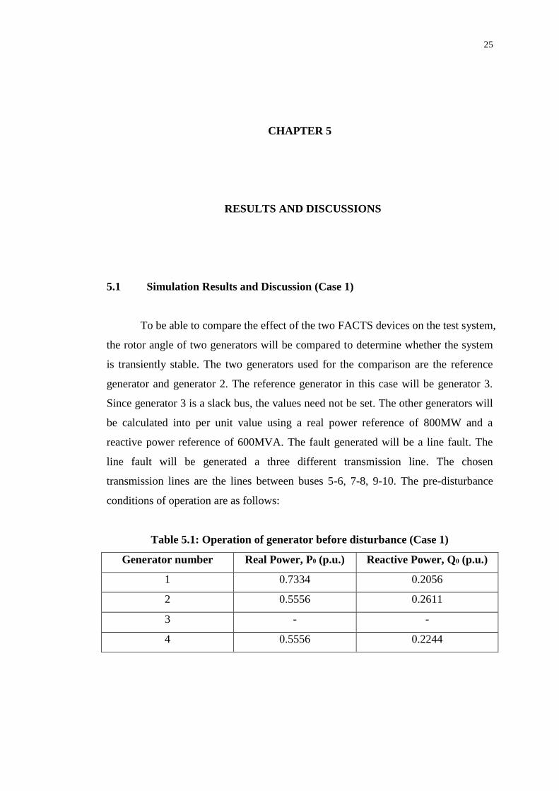
5.1 Simulation Results and Discussion (Case 1)
To be able to compare the effect of the two FACTS devices on the test system,
the rotor angle of two generators will be compared to determine whether the system
is transiently stable. The two generators used for the comparison are the reference
generator and generator 2. The reference generator in this case will be generator 3.
Since generator 3 is a slack bus, the values need not be set. The other generators will
be calculated into per unit value using a real power reference of 800MW and a
reactive power reference of 600MVA. The fault generated will be a line fault. The
line fault will be generated a three different transmission line. The chosen
transmission lines are the lines between buses 5-6, 7-8, 9-10. The pre-disturbance
conditions of operation are as follows:
Table 5.1: Operation of generator before disturbance (Case 1)
Generator number Real Power, P0 (p.u.) Reactive Power, Q0 (p.u.)
1 0.7334 0.2056
2 0.5556 0.2611
3 - -
4 0.5556 0.2244

26
Figure 5.1: Case 1 no fault
To ensure that the FACTS devices are functioning properly, a graph with no
fault introduced is generated. Next, a graph with fault introduced but not cleared is
also generated to show the presence of a fault. After that, the FACTS devices will be
introduced to clear the fault.
Figure 5.2: Case 1 fault between bus 5 and 6

27
Figure 5.3: Case 1 comparison of performance of UPFC and GUPFC (bus 5-6 fault)
The results shown above are when a fault has occurred at the transmission
line between bus 5 and bus 6. The fault is introduced into the 12 bus test system
during the 0.5s mark. The FACTS device will then respond during the 0.6s mark. In
Figure 5.2, it is shown that when a line fault has occurred, the generators have gone
out of synchronism, thus the increasing differences in the rotor angle. This is a sign
of a system going unstable and is very harmful for the generators. Not only that,
situations like this will normally cause power supply fluctuation and sometimes even
a black out as well.
Figure 5.3 shows the recovery of the system when FACTS devices are
introduced into the system 0.1s after the fault had occurred. That is the time that is
set for the FACTS devices to respond when instability has been detected in the
system. From the figure, it is clear that the GUPFC device is able to stabilize the
system and get the generators back into synchronism faster than the UPFC device.
Although the GUPFC device has allowed the system to swing at a higher angle
during the first swing, it is able to recover the system faster and thus reaching
transient stability faster than the UPFC device.
28
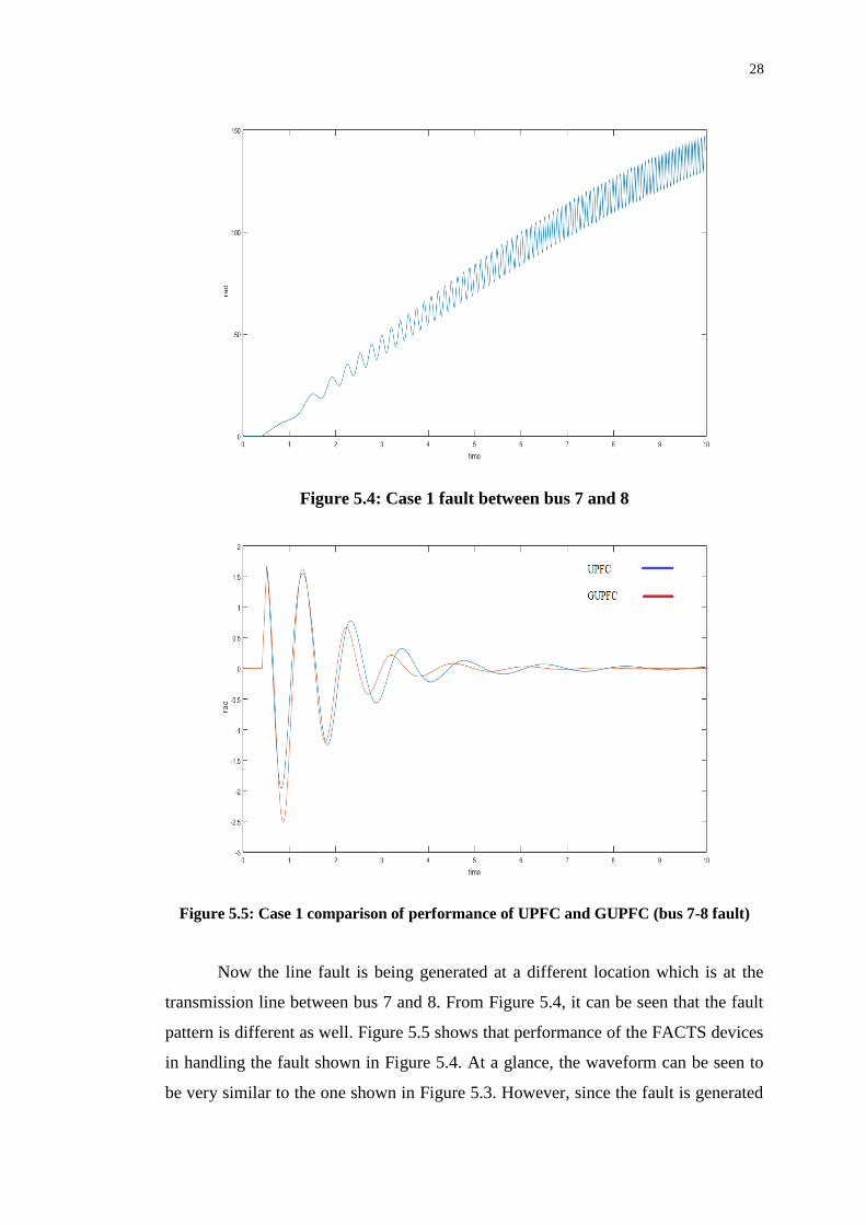
Figure 5.4: Case 1 fault between bus 7 and 8
Figure 5.5: Case 1 comparison of performance of UPFC and GUPFC (bus 7-8 fault)
Now the line fault is being generated at a different location which is at the
transmission line between bus 7 and 8. From Figure 5.4, it can be seen that the fault
pattern is different as well. Figure 5.5 shows that performance of the FACTS devices
in handling the fault shown in Figure 5.4. At a glance, the waveform can be seen to
be very similar to the one shown in Figure 5.3. However, since the fault is generated

29
at a different location, the fault is also less steep compared to the line fault generated
between bus 5 and 6. As a result, when the FACTS devices respond to the fault that
has occurred, the angle is slightly less than the one shown in Figure 5.3. That being
said, the waveform in Figure 5.5 has shown that although the fault has occurred at a
different location, the performance of the FACTS devices remain. This is evident as
the GUPFC device is able to bring the system to a transient stability state faster than
the UPFC device.
Figure 5.6: Case 1 fault between bus 9 and 10

30
Figure 5.7: Case 1 comparison of performance of UPFC and GUPFC (bus 9-10 fault)
The third location for the transmission line fault to occur is in between bus 9
and 10. Figure 5.6 shows again that the fault waveform is different since the location
of fault has now changed as well. This result shows a similar pattern to all the
comparison of performance of the FACTS devices as shown in previous results.
From all the three results shown above, it is evident that the GUPFC device is able to
respond to faults better when compared to a UPFC device. Although not by much,
the GUPFC device is able to bring the system to a state of transient stability faster
than the UPFC device. Not only that, it is also able to stabilize the system faster than
the UPFC device as shown in Figure 5.3, Figure 5.5 and Figure 5.7.
Another way of determining the performances of both the UPFC and GUPFC
devices is to check its ability to maintain the voltage of its sending end and receiving
end buses. The series converters of both FACTS devices are able to maintain the
voltage of the buses that it is controlling. Normally, the voltage between buses is
maintained at a fixed rating. However, if fault is introduced to the system, the voltage
may increase or decrease. Fluctuation like this is undesirable in a power system. The
results shown in Table 5.2 are the recorded voltages during the simulation shown
above.

31
Table 5.2: Voltage comparison of UPFC and GUPFC device
Fault area Voltage between controlled bus (p.u.)
UPFC GUPFC
Steady state Highest recorded Steady state Highest recorded
5-6 0.9641 1.1784 0.9653 1.1553
7-8 0.9653 1.1182 0.9653 1.1527
9-10 0.9652 1.1928 0.9653 1.1527
From the results shown in Table 5.2, it is shown that the FACTS devices are
able to recover from the fault and maintain the voltage level from before fault
condition. However, as seen from Table 2, the GUPFC device is able to give a more
consistent result compared to the UPFC device which shows fluctuation depending
on the location of the fault. This can be due to the fact that since the GUPFC device
has more control on the power system due to the presence of an extra receiving end,
it is able to control the voltage better than the UPFC device which only has one
receiving end. Overall, this shows that the GUPFC device has more control of the
power system when compared to the UPFC device.
5.2 Simulation Results and Discussion (Case 2)
A second case is presented to ensure that the results of the effectiveness of
the FACTS devices are represented accordingly. The faults generated here will be the
same as the ones in case 1. However, the pre-disturbance conditions of operation are
changed. The reference generator and the reference power value remains the same as
well. The comparison between the UPFC device and the GUPFC device are the same
as case 1 as well. The pre-disturbance conditions are presented in Table 5.2:

32
Table 5.3: Operation of generator before disturbance (Case 2)
Generator number Real Power, P0 (p.u.) Reactive Power, Q0 (p.u.)
1 0.5556 0.2556
2 0.5556 0.4611
3 - -
4 1.5556 0.2244
Figure 5.8: Case 2 fault between bus 5 and 6
Figure 5.9: Case 2 comparison of performance of UPFC and GUPFC (bus 5-6 fault)

33
Case 2 is similar to case 1 in the sense that a line fault has occurred between
buses in different locations. However, as seen from Table 5.2, generator 4 has its real
power increased by 1 p.u. Figure 5.8 shows that the fault has occurred. Although the
angle is in a different direction, a fault has still occurred that allowed the system to
go out of control. Figure 5.9 shows the response of the FACTS devices in dealing
with the fault that has occurred. Since the power has been increased, the system
shows higher fluctuation and amplitude compared to the results obtained from case 1.
Results in Figure 5.9 show a better comparison of performance of both FACTS
devices. From the figure, it is apparent that the GUPFC device is able to bring the
system into transient stability faster than the UPFC device. By the time, the GUPFC
device has brought the system into a steady state, the system controlled by the UPFC
device still shows signs of fluctuation.
Figure 5.10: Case 2 fault between bus 7 and 8

34
Figure 5.11: Case 2 comparison of performance of UPFC and GUPFC (bus 7-8 fault)
Result shown in Figure 5.11 shows very little difference from the result of
Figure 5.9.
Figure 5.12: Case 2 fault between bus 9 and 10
35
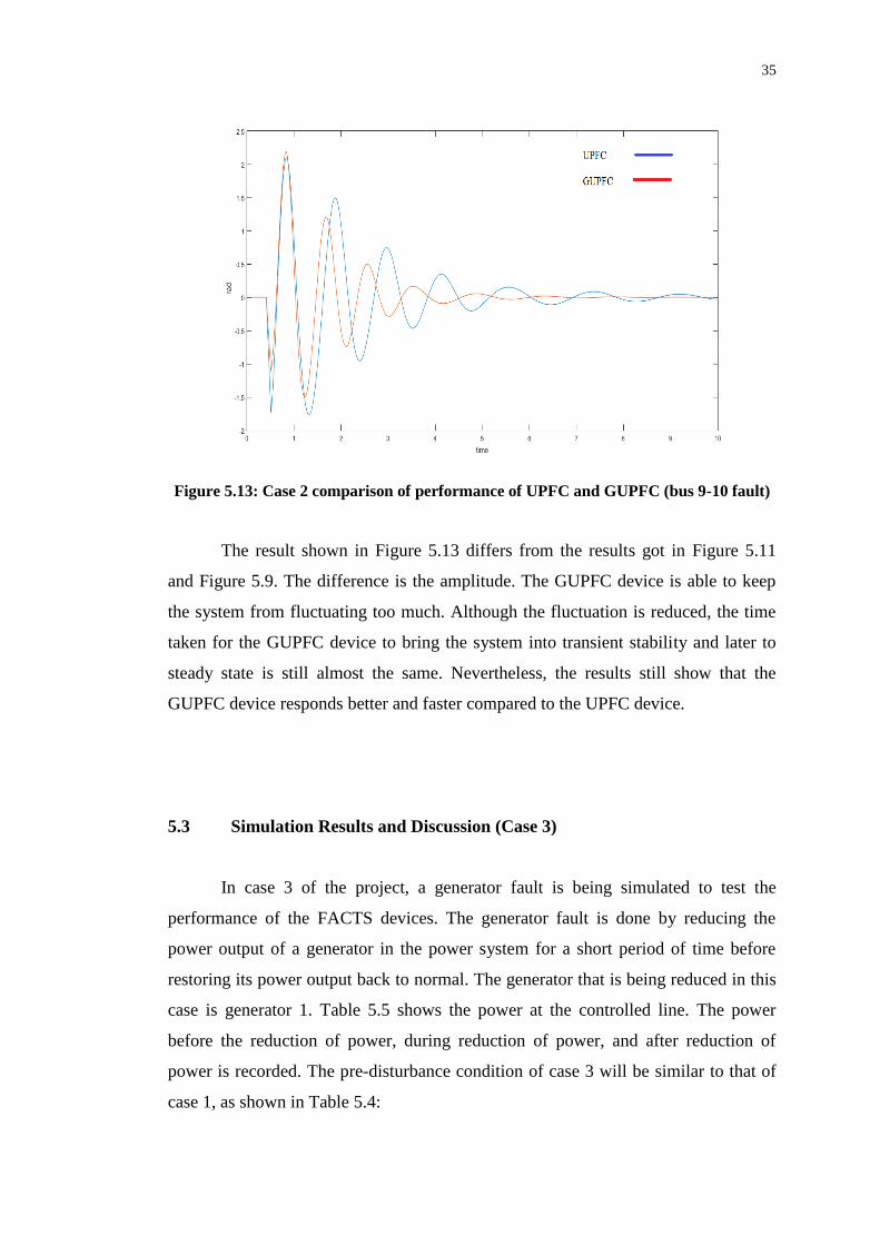
Figure 5.13: Case 2 comparison of performance of UPFC and GUPFC (bus 9-10 fault)
The result shown in Figure 5.13 differs from the results got in Figure 5.11
and Figure 5.9. The difference is the amplitude. The GUPFC device is able to keep
the system from fluctuating too much. Although the fluctuation is reduced, the time
taken for the GUPFC device to bring the system into transient stability and later to
steady state is still almost the same. Nevertheless, the results still show that the
GUPFC device responds better and faster compared to the UPFC device.
5.3 Simulation Results and Discussion (Case 3)
In case 3 of the project, a generator fault is being simulated to test the
performance of the FACTS devices. The generator fault is done by reducing the
power output of a generator in the power system for a short period of time before
restoring its power output back to normal. The generator that is being reduced in this
case is generator 1. Table 5.5 shows the power at the controlled line. The power
before the reduction of power, during reduction of power, and after reduction of
power is recorded. The pre-disturbance condition of case 3 will be similar to that of
case 1, as shown in Table 5.4:

36
Table 5.4: Operation of generator before disturbance (Case 3)
Generator number Real Power, P0 (p.u.) Reactive Power, Q0 (p.u.)
1 0.7334 0.2056
2 0.5556 0.2611
3 - -
4 0.5556 0.2244
Table 5.5: Results of generator fault
FACTS device Power of controlled line (p.u.)
Before Reduced After
GUPFC Line 1 0.3161 0.7561 0.4312
Line 2 0.6096 0.7850 0.6082
UPFC Line 1 0.7568 1.1182 0.7688
From the results shown in Table 5.5, the power of between the buses that the
FACTS devices are controlling is shown. The table has shown that both FACTS
devices are able to control the real power of the buses so that the system is able to
achieve transient stability. In this case, for the system to stay transiently stable, the
power flow is important. When the generator fault has occurred whereby the power
of generator 1 is reduced, the FACTS device will be responsible to redirect power
flow so that the whole power system can still remain transiently stable.
This can be seen from Table 5.5, as both FACTS devices show an increase in
power flow between the buses that the devices control. That being said, since the
GUPFC device is controlling more buses, it is able to redirect power flow more
efficiently compared to the UPFC device. After the generator is returned to its
normal state, the power flow is restructured to allow for optimum power flow in the
system. This can be seen when the power at line 1 of the GUPFC device has risen
from 0.3161 p.u. to 0.4312 p.u. to cater for the demand of the power system.

37
CHAPTER 6
6 CONCLUSION AND RECOMMENDATION
6.1 Conclusion
To conclude this project, the comparison of performance of the GUPFC
device and the UPFC device has shown significant results towards the improvement
of transient stability in a power system application. The GUPFC device has shown
that its performance is able to outshine that of the older FACTS model which is the
UPFC device. By using the GUPFC device in a power system, the system is able to
achieve transient stability faster than the UPFC device with a faster response as well.
As a result, the system which uses the GUPFC device can be brought back to its
steady state faster than when a UPFC device is used. Nevertheless, the UPFC device
is still a viable FACTS device as it is still able to achieve the same results albeit a
longer time taken. The UPFC device’s performance can be improved if a better
controller can be installed alongside it. For a power system application of a smaller
scale, it is viable to still use a UPFC device. However, when a larger scale of power
system is involved, the GUPFC device will be a better option from then on. By
working on this project, the CSC is definitely recommended for more power system
application as the versatility it offers can be advantageous in many situations. In
conclusion, the comparison of the CSC performance in a power system application
posed positive results for it.

38
6.2 Recommendation
For starters, adding additional controllers to the FACTS device can slightly
improve its transient stability performance. The controllers will have to be tuned to
suit the power system involved as well. By using an optimal power flow programme,
the parameters for the controller can be found out easily. Implementation of a
controller together with the UPFC device will definitely improve its transient
stability performance, although the performance might still not be able to match the
performance of a GUPFC device. To further improve on this project, a third
receiving end and even a second sending end can be added to the GUPFC device for
better performance from the device. By controlling more buses in a power system,
the GUPFC device will be able to control real and reactive power exchange at more
buses, resulting in a better transient stability performance. Other than that, an energy
storage system can also be paired with the GUPFC device to further improve the
exchange of real and reactive power.

39
REFERENCES
Arabi, S., H. Hamadanizadeh, and B. Fardanesh. "Convertible Static Compensator
Performance Studies On The NY State Transmission System". IEEE Power
Engineering Society Summer Meeting, n. pag. Web. 4 Apr. 2016.
Babaei, S. et al. "Convertible Static Compensator (CSC) Performance Under System
Fault". 2012 IEEE Power and Energy Society General Meeting (2012): n. pag.
Web. 15 Mar. 2016.
Fardanesh, B. et al. "Multi-Converter FACTS Devices: The Generalized Unified
Power Flow Controller (GUPFC)". 2000 Power Engineering Society Summer
Meeting (Cat. No.00CH37134) n. pag. Web. 10 Apr. 2016.
Galvani, Sadjad, Mohamad Bagher Banna Sharifian, and Mehrdad Tarafdar Hagh.
"Unified Power Flow Controller Impact On Power System Predictability". IET
Generation, Transmission & Distribution 8.5 (2014): 819-827. Web. 17 June
2016.
Johnson, B.K. "How FACTS Controllers Function In An AC Transmission System:
Series And Combined Multiterminal Controllers". 2003 IEEE PES Transmission
and Distribution Conference and Exposition (IEEE Cat. No.03CH37495) n. pag.
Web. 18 Mar. 2016.
Kamarposhti, M. "The Effect Of Upfc Proper Placement On The Limit Of The Static
Loading In The Power System". Trakia Journal of Science 12.4 (2014): 431-440.
Web. 18 Mar. 2016.
Kumar, Ravinder and Ashwani Kumar. "Impact Of Unified Power Flow Controller
Control Parameters On Available Transfer Capability". 2015 International
Conference on Energy, Power and Environment: Towards Sustainable Growth
(ICEPE) (2015): n. pag. Web. 21 June 2016.
Kundur, P., 1994. Transient stability. In: Power System Stability and Control. New
York: McGraw-Hill.
Lin Sun, et al. "Application Of GUPFC In China's Sichuan Power Grid - Modeling,
Control Strategy And Case Study". 2003 IEEE Power Engineering Society
General Meeting (IEEE Cat. No.03CH37491) n. pag. Web. 14 Mar. 2016.

40
Lin, Li et al. "Transient Stability Mechanism Of DFIG Wind Farm And Grid-
Connected Power System". 2013 IEEE Grenoble Conference (2013): n. pag. Web.
25 Mar. 2016.
Lubis, Rakhmad Syafutra. "Modeling And Simulation Of Generalized Unified Power
Flow Controller (GUPFC)". 2011 2nd International Conference on
Instrumentation, Communications, Information Technology, and Biomedical
Engineering (2011): n. pag. Web. 27 Mar. 2016.
Lubis, Rakhmad Syafutra, Sasongko Pramono Hadi, and Tumiran. "Modeling Of The
Generalized Unified Power Flow Controller For Optimal Power Flow".
Proceedings of the 2011 International Conference on Electrical Engineering and
Informatics (2011): n. pag. Web. 16 Mar. 2016.
Okeke, Therese Uzochukwuamaka and Ramy Georgious Zaher. "Flexible AC
Transmission Systems (FACTS)". 2013 International Conference on New
Concepts in Smart Cities: Fostering Public and Private Alliances (SmartMILE)
(2013): n. pag. Web. 19 Mar. 2016.
Ray, Aniruddha and Jayalakshmi O. Chandle. "Voltage Stability Enhancement
During Excess Load Increments Through Optimal Location Of UPFC Devices".
2015 International Conference on Technological Advancements in Power and
Energy (TAP Energy) (2015): n. pag. Web. 20 July 2016.
Santos, Natalia Rosa M., V. Fernao Pires, and R. M. Castro. "Modeling Of The
Generalized Unified Power Flow Controller To Integrate In Power Flow Studies".
4th International Conference on Power Engineering, Energy and Electrical
Drives (2013): n. pag. Web. 17 Mar. 2016.
Shakil, S. Fahad Bin et al. "Improving The Voltage Stability And Performance Of
Power Networks Using Power Electronics Based FACTS Controllers". 2014
International Conference on Energy Systems and Policies (ICESP) (2014): n. pag.
Web. 17 Mar. 2016.
Sharma, N K and P P Jagtap. "Modelling And Application Of Unified Power Flow
Controller (UPFC)". 2010 3rd International Conference on Emerging Trends in
Engineering and Technology (2010): n. pag. Web. 4 Apr. 2016.
Sheng-Huei Lee, and Chia-Chi Chu. "Power Flow Computations Of Convertible
Static Compensators For Large-Scale Power Systems". IEEE Power Engineering
Society General Meeting, 2004. n. pag. Web. 16 Mar. 2016.
Stella, V., 2005. Variable Structure Adaptive Fuzzy and Neutral Network Controllers
for Facts Devices. Doctor of Philisophy. Multimedia University.

41
Sun, J. et al. "Operating Characteristics Of The Convertible Static Compensator On
The 345 Kv Network". IEEE PES Power Systems Conference and Exposition,
2004. n. pag. Web. 14 Mar. 2016.
Tiwari, R., K. R. Niazi, and V. Gupta. "Optimal Location Of FACTS Devices For
Improving Performance Of The Power Systems". 2012 IEEE Power and Energy
Society General Meeting (2012): n. pag. Web. 15 Apr. 2016.
Uzunovic, E. et al. "NYPA Convertible Static Compensator (CSC) Application
Phase I: STATCOM". 2001 IEEE/PES Transmission and Distribution Conference
and Exposition. Developing New Perspectives (Cat. No.01CH37294) n. pag. Web.
19 Apr. 2016.
Vural, A. Mete and Mehmet Tümay. "Mathematical Modeling And Analysis Of A
Unified Power Flow Controller: A Comparison Of Two Approaches In Power
Flow Studies And Effects Of UPFC Location". International Journal of Electrical
Power & Energy Systems 29.8 (2007): 617-629. Web. 10 Apr. 2016.
Xiao-Ping Zhang, E. Handschin, and M. Yao. "Modeling Of The Generalized
Unified Power Flow Controller (GUPFC) In A Nonlinear Interior Point OPF".
IEEE Trans. Power Syst. 16.3 (2001): 367-373. Web. 5 Apr. 2016.

42
APPENDICES
APPENDIX A: Tables of Data
The unit of the parameters of the studied system is in per unit (p.u.), unless
otherwise specified.
Table A1: Load Data for IEEE 12 bus test system
Bus no. Bus code Load Impedance
1 2 0
2 2 0
3 1 0
4 2 0
5 0 0
6 0 0
7 0 (697-j100)/900
8 0 0
9 0 0
10 0 (1767-j250)/900
11 0 (786-j200)/900
12 0 0
(Bus code: 1. Slack bus, 2. PQ bus)

43
Table A2: Line Data for IEEE 12 bus test system
Sending
end bus
Receiving
end bus
Resistance,
R (p.u.)
Reactance,
X (p.u.)
Susceptance,
B (p.u.)
Transformer
Tap
1 12 0 0.15 0 0
12 11 0 0.0028 0 0
11 2 0 0.15 0 0
11 10 0 0.0011 0 0
10 9 0 0.0061 0 0
9 8 0 6.1111x10^-
4
0 0
8 7 0 6.1111x10^-
4
0 0
7 6 0 0.0011 0 0
6 4 0 0.15 0 0
6 5 0 0.0028 0 0
5 3 0 0.15 0 0
Table A3: Generator Data for IEEE 12 bus test system
Bus Number 1 2 3 4
d-axis reactance 1.8 1.8 1.8 1.8
q-axis reactance 1.7 1.7 1.7 1.7
d-axis transient reactance 0.3 0.3 0.3 0.3
Inertia constant 6.5 6.5 6.175 6.175
Maximum direct axis excitation voltage 7.8 7.8 7.8 7.8
Minimum direct axis excitation voltage -6.7 -6.7 -6.7 -6.7
d-axis equivalent transient rotor time constant 8 8 8 8
q-axis transient reactance of the generator 0.65 0.65 0.65 0.65
q-axis equivalent transient rotor time constant 1.5 1.5 1.5 1.5