comparison of air kerma measurements between the ptb and
TRANSCRIPT

Metrologia 2013, 50, Tech. Suppl., 06008
Page 1/16
Comparison of air kerma measurements between the PTB and the IAEA
for x-radiation qualities used in
general diagnostic radiology and mammography
István Csete1, Ludwig Büermann
2, Igor Gomola
1, Reinhard Girzikowsky
3
1 International Atomic Energy Agency (IAEA), Vienna, Austria 2 Physikalisch-Technische Bundesanstalt, Bundesallee 100, 38116 Braunschweig, Germany 3 Formerly at International Atomic Energy Agency (IAEA), Vienna, Austria
E-mail: [email protected]
Abstract
A comparison of the air kerma standards for x-radiation qualities used in general diagnostic
radiology and mammography, identified as EURAMET.RI(I)-S10 (EURAMET project #1221), was
performed between the PTB and the IAEA. Two spherical and two parallel-plate reference-class
ionization chambers of the IAEA and 12 beam qualities standardized in the IEC standard
61267:2005 plus additional 7 standard beam qualities established at both laboratories were selected
for the comparison. The calibration coefficients were determined for the transfer chambers at the
PTB in September 2012 and before and after this at the IAEA Dosimetry Laboratory. The results
show the calibration coefficients of both laboratories to be in good agreement within the standard
uncertainty of the comparison of about 0.47 %.
1. Introduction
The IAEA Dosimetry Laboratory, DOL, in Seibersdorf Austria, performs calibration of reference
diagnostic dosemeters of IAEA/WHO SSDL1 Network members (more than 80 laboratories
worldwide). As a signatory of the CIPM MRA, the DOL maintains a quality management system
(QMS) complying with ISO 17025. The DOL published its dosimetry CMC claims in 2007, in the
Appendix C database of the CIPM MRA. To maintain these CMC claims, periodically updated
“supporting evidence” for the measuring capabilities is required in addition to the traceability of the
measured quantities. The first similar comparison was the EUROMET.RI(I)-S4 comparison with 13
participants started in 2000. Its result was published in 2004 [1]. In the meantime the DOL changed
the beam qualities and measurement standards. This comparison of air kerma standards between the
IAEA and the PTB is intended to support the measurement and calibration service offered by the
IAEA for radiation qualities used in general diagnostic radiology and mammography.
The relevant IAEA secondary standard ionization chambers are traceable to the PTB in terms of air
kerma, being calibrated every three years. The comparison partner PTB maintains primary
standards of air kerma for radiation qualities used in diagnostic radiology and mammography with
degrees of equivalence (DoE) in the key comparison database (KCDB) of the CIPM MRA based on
the PTB results in the key comparisons BIPM.RI(I)-K2 (low-energy x-rays), K3 (medium-energy x-
rays) and K7 (mammography x-rays) [2-4].
The current bilateral comparison is identified as EURAMET project #1221 and registered in the
KCDB as EURAMET.RI(I)-S10 supplementary comparison. The Technical Protocol [5] was
approved by the CCRI(I).
2. Comparison procedure
2.1 Transfer chambers
For the comparisons four IAEA reference-class transfer chambers were selected. The
technical details of the chambers are listed in Table 1. The reference plane of the spherical
chambers is the centre of the sphere. For the parallel-plate Radcal and Magna chambers the
reference planes are the grooves on their side wall at 4 mm behind the plane of their
entrance windows.

Metrologia 2013, 50, Tech. Suppl., 06008
Page 2/16
Table 1 Technical data for the transfer chambers
Type Reference
point
Nominal
volume
(cm3)
*Polarizing
voltage
(V)
Wall
thickness
Outer
diameter
(mm)
Exradin A3,
spherical chamber
#XR071832
chamber
centre 3.6 +300 0.25 mm 19.5
Exradin A4,
spherical chamber
#P=XP072344
chamber
centre 30 +500 0.50 mm 39.2
Radcal RC6M
parallel plate chamber
#10183
marked on the
chamber 6 +300 0.7mg/cm
2
43
30 (effective)
Magna A 650
parallel plate chamber
#D121351
marked on the
chamber 3 +300 3.9 mg/cm
2
53
42 (effective)
* Applied to the central electrode
2.2 Radiation qualities
The radiation qualities used for the comparison were a subset of the RQR, RQA, RQT,
RQR-M, RQA-M standard beam qualities of the international standard IEC 61267:2005 [6]
and some additional mammographic radiation qualities not included in the standard, as
listed in Table 2.
Table 2. Technical data of the radiation qualities
Quality code
(IEC 61267)
Tube voltage
PTB HVL
IAEA HVL
HVL
(IEC 61267)
(kV) (mm Al) (mm Al) (mm Al)
1 RQR-2 40 1.42 1.46 1.42
2 RQR-5 70 2.60 2.61 2.58
3 RQR-10 150 6.55 6.76 6.57
4 RQA-2 40 2.18 2.27 2.2
5 RQA-5 70 6.76 6.97 6.8
6 RQA-10 150 13.23 13.52 13.3
7 RQT-9 120 8.48 8.56 8.4
8 RQR-M1 25 0.283 0.300 0.28
9 RQR-M2 28 0.314 0.332 0.31
10 RQR-M3 30 0.331 0.352 0.33
11 RQR-M4 35 0.366 0.391 0.36
12 *MMV-40 40 0.392 0.421 ---
13 *MMV-50 50 0.428 0.461 ---
14 RQA-M2 28 0.61 0.629 0.60
15 *MMH-40 40 0.871 0.822 ---
16 *MMH-50 50 0.908 0.957 ---
17 *MRV-28 28 0.375 0.400 ---
18 *MRV-30 30 0.393 0.419 ---
19 *MRV-35 35 0.425 0.455 ---
*PTB code

Metrologia 2013, 50, Tech. Suppl., 06008
Page 3/16
2.3 Reference conditions
The calibration coefficients of the transfer chambers were given in terms of air kerma per
charge in units of Gy/C and referred to standard conditions of air temperature, pressure and
relative humidity of T = 293.15 K, P = 101.325 kPa and h = 50 %. The ambient conditions
(temperature, pressure and humidity) during the calibrations were monitored continuously.
The observed variations were in the ranges (295-297) K, (98.0-101.0) kPa and (45-60) %,
respectively, in both laboratories. The calibration distance (distance from x-ray tube focus
to reference plane) was 1000 mm at both laboratories.
3. Calibration at the PTB
3.1 X-ray facilities
The PTB mammographic beam qualities used in this comparison are produced with a
unipolar x-ray tube of type Panalytical PW2185/Mo with a Mo anode angle of 26°
combined with a constant potential generator. The inherent filtration is 1 mm beryllium,
with the additional filtration being either 0.03 mm molybdenum or 0.025 mm rhodium,
depending on the type of beam quality. Mammographic radiation qualities are established
for tube voltages in the range from 20 kV to 50 kV. The diameter of the circular beam at
1 m distance from the focus was 10 cm. The air kerma rates were about 45 mGy/min and
5 mGy/min in the non-attenuated and attenuated beams, respectively.
The IEC 61267 RQR, RQA and RQT radiation qualities used in this comparison are
produced with a unipolar x-ray tube of type Comet MXR 165 with a W anode angle of 30°
combined with a constant potential generator. The inherent filtration is 4 mm beryllium.
The diameter of the circular beam at 1 m distance from the focus was 8 cm. The air kerma
rates were about 3 mGy/min, 20 mGy/min and 70 mGy/min in the RQA, RQR and RQT
beams, respectively.
For both x-ray facilities the high voltage was measured invasively with a voltage divider
manufactured and calibrated at PTB. Photon fluence spectra of all radiation qualities were
measured with a high-purity germanium detector. Characteristic radiation quality data such
as mean energies and half-value layers are evaluated from these spectra. The first Al-half-
value layers of the qualities used in this comparison are listed in Table 2.
A transmission-type monitor chamber manufactured at PTB was used at both facilities to
normalize the x-ray output. A thermistor measures the temperature of the air inside the
shielding box surrounding the free-air chamber. Air pressure is measured by means of a
calibrated barometer positioned in the irradiation room. The PTB laboratory humidity is not
controlled because it varies between 30 % and 60 % and this is taken into account by an
additional uncertainty in the humidity correction factor. No humidity correction was
applied to the current measured using the transfer instrument. Each calibration is based on 5
repeated measurements of the ionization charge measured in 60 s with the standard and the
chamber to be calibrated. The leakage is measured before and after the 5 repeated
measurements and the mean value is subtracted from the mean of the measured charge.
Beam profiles of the mammography radiation qualities in 1 m distance from the focus and
nominal field size of 10 cm in diameter were measured with a flat panel image sensor type
Hamamatsu C7942. This sensor has 2400 x 2400 pixels of size 50 mm and thus covers an
area of 12 cm x 12 cm. As an example, the profile of the IEC 61267 RQR-M2 radiation
quality is shown in Figure 1.

Metrologia 2013, 50, Tech. Suppl., 06008
Page 4/16
0 1 2 3 4 5 6 7 8 9 10 11 12
0,0
0,1
0,2
0,3
0,4
0,5
0,6
0,7
0,8
0,9
1,0
x-profile (horizontal)
y-profile (vertical)
rela
tive
pix
el co
nte
nt
pixel position / cm
Figure 1. PTB beam profile of the IEC 61267 RQR-M2 radiation quality. 3D profile plot produced
with the software package „ImageJ” (upper) and x- and y- profile plots extracted from the pixel
image (lower). The anode - cathode axis is oriented horizontally so that the hHeel effect is visible in
the horizontal profile.
The horizontal intensity profile reflects the expected distribution due to the Heel-effect
which causes a reduction in the x-ray beam intensity toward the anode side of the x-ray
field. As the aperture of the PK100 free air chamber was 2 cm in diameter (see 3.2) and the
mammographic transfer chambers sensitive volume cross sections were not significantly
larger, no beam non-uniformity correction was applied. However, a type B uncertainty of
0.1 % was included in the uncertainty budget (see Table 8).
Metrologia 2013, 50, Tech. Suppl., 06008
Page 5/16
3.2 Determination of the air-kerma rate
The PTB maintains two primary standard free-air chambers. One is of the parallel-plate
type and named “PK100” which can be used for radiation qualities produced with tube
voltages between 10 kV and 100 kV. The other is of cylindrical type and named
“Fasskammer (FK)” which can be used for radiation qualities produced with tube voltages
between 30 kV and 300 kV.
For a free-air ionization chamber standard with measuring volume V, the air-kerma rate is
determined by the relation
i
ikge
W
V
IK
air
air
air 1
1
(1)
where air is the density of air under reference conditions, I is the ionization current under
the same conditions, Wair is the mean energy expended by an electron of charge e to
produce an ion pair in air, gair is the fraction of the initial electron energy lost through
radiative processes in air, and ki are the correction factors to be applied to the standard.
The values used for the physical constants air and Wair /e are given in Table 3. For use with
this dry-air value for air, the ionization current I must be corrected for humidity and for the
difference between the density of the air of the measuring volume at the time of
measurement and the value given in the table.
Table 3. Physical constants used in the determination of the air-kerma rate
Constant Value uia
airb 1.2930 kg m
–3 0.0001
Wair / e 33.97 J C–1 0.0015
a ui is the relative standard uncertainty.
b Density of dry air at T0 = 273.15 K and P0 = 101.325 kPa.
3.3 Free-air chamber type “PK100”
The free-air chamber type “PK100” is in use as a primary air kerma standard for
x-radiations produced with tube voltages between 10 kV and 100 kV. The measuring
volume V is defined by the diameter of the chamber aperture and the length of the
collecting region. Details of the PTB standard “PK100” are given in [7]. The main
dimensions, the measuring volume and the polarizing voltage for this standard are shown in
Table 4.
Table 4. Main characteristics of the free-air standard PK100
Aperture diameter / mm 20.008
Air path length / mm 97.2
Collecting length / mm 20.021
Electrode separation / mm 234
Collector width / mm 240
Measuring volume / mm3 6294.7
Polarizing voltage / V 6000

Metrologia 2013, 50, Tech. Suppl., 06008
Page 6/16
Correction factors for the PK100 were calculated by means of Monte Carlo methods and
mean values for radiation qualities were determined based on the measured photon fluence
spectra. Values and uncertainties of the correction factors of the PK100 for the radiation
qualities used in this comparison are given in Tables 5 and 6.
Table 5. Correction factors for the PTB standard for non-attenuated Mo/Mo beams
Radiation quality
PTB code
IEC 61267 code
MMV 25
RQR-M1
MMV 28
RQR-M2
MMV 30
RQR-M3
MMV 35
RQR-M4
MMV 40
-
MMV 50
-
uiA uiB
Air attenuation kaa 1.0255 1.0234 1.0223 1.0205 1.0192 1.0176 0.05 0.05
Scattered radiation kscb 0.9905 0.9907 0.9908 0.9910 0.9911 0.9913 - 0.05
Electron loss ke 1.0000 1.0000 1.0000 1.0000 1.0000 1.0000 - 0.05
Ion recombination ks 1.0052 1.0053 1.0052 1.0054 1.0056 1.0059 0.05 0.05
Guard strip attenuation kap 1.0052 1.0048 1.0046 1.0042 1.0040 1.0037 0.05 0.05
Aperture edge trans. kl 0.9997 0.9996 0.9996 0.9996 0.9996 0.9996 - 0.05
Field distortion 0.9920 0.9920 0.9920 0.9920 0.9920 0.9920 - 0.15
Wall transmission kp 1.0000 1.0000 1.0000 1.0000 1.0000 1.0000 0.05 -
Polarity kpol 1.0000 1.0000 1.0000 1.0000 1.0000 1.0000 - 0.05
Humidity kh 0.9980 0.9980 0.9980 0.9980 0.9980 0.9980 - 0.05
a Values for 293.15 K and 101.325 kPa; each measurement is corrected using the air density measured at the
time. b This correction includes the re-absorption of scattered and of fluorescent photons.
Table 6. Correction factors for the PTB standard for attenuated Mo/Mo beams and Mo/Rh
beams
Radiation quality
PTB code
IEC 61267 code
MMH 28
RQR-M2
MMH40
-
MMH 50
-
MRV 28
-
MRV 30
-
MRV 35
-
uiA uiB
Air attenuation kaa 1.0114 1.0096 1.0088 1.0197 1.0189 1.0176 0.05 0.05
Scattered radiation kscb 0.9919 0.9924 0.9927 0.9910 0.9911 0.9913 - 0.05
Electron loss ke 1.0000 1.0000 1.0000 1.0000 1.0000 1.0000 - 0.05
Ion recombination ks 1.0010 1.0011 1.0010 1.0056 1.0045 1.0049 0.05 0.05
Guard strip attenuation kap 1.0024 1.0021 1.0020 1.0041 1.0039 1.0036 0.05 0.05
Aperture edge trans. kl 0.9995 0.9993 0.9992 0.9996 0.9996 0.9996 - 0.05
Field distortion 0.9920 0.9920 0.9920 0.9920 0.9920 0.9920 - 0.15
Wall transmission kp 1.0000 1.0000 1.0000 1.0000 1.0000 1.0000 0.05 -
Polarity kpol 1.0000 1.0000 1.0000 1.0000 1.0000 1.0000 - 0.05
Humidity kh 0.9980 0.9980 0.9980 0.9980 0.9980 0.9980 - 0.05
a Values for 293.15 K and 101.325 kPa; each measurement is corrected using the air density measured at the time. b This correction includes the re-absorption of scattered and of fluorescent photons.

Metrologia 2013, 50, Tech. Suppl., 06008
Page 7/16
The relative standard uncertainties associated with the air-kerma rate determination using
the PK100 are summarized in Table 7 and result in a combined standard uncertainty of
0.30 %. They were evaluated according to the GUM [8].
Table 7. Relative standard uncertainties (in %) associated with the standard PK100
Source of uncertainty Type A Type B Ionization current 0.10 0.06
Volume 0.06
Positioning 0.01
Correction factors 0.09 0.21
Physical constants 0.15
PK100K 0.13 0.27
0.30
The uncertainty components for the calibration of a secondary-standard ionization chamber
in terms of air kerma with the PK100 are listed in Table 8. If the uncertainties in the
physical constants and correction factors are omitted, the uncertainty budget shown in
Table 9 is obtained.
Table 8. Relative standard uncertainties (in %) associated with the calibration of the transfer
ionization chambers
Source of uncertainty Type A Type B
Air-kerma rate LABK 0.13 0.27
Ionization current 0.10 0.06
Positioning 0.05
Monitor normalization 0.05
Air density correction 0.05
Beam non-uniformity 0.10
NK,PTB 0.18 0.30
0.35
Table 9. Relative standard uncertainties (in %) associated with the calibration of the transfer
ionization chambers at PTB omitting the uncertainties due to the physical constants
and correction factors of the standard PK100
Source of uncertainty Type A Type B
Air-kerma rate PK100K 0.10 0.06
Ionization current 0.10 0.06
Positioning 0.05
Monitor normalization 0.05
Air density correction 0.05
Beam non-uniformity 0.10
NK,PTB 0.16 0.14
0.21
3.4 Free-air chamber type “Faßkammer”
The PTB cylindrical free-air chamber FK is in use as a primary air-kerma standard for
x-radiations produced with tube voltages between 30 kV and 300 kV. A set of five central
collecting electrodes, each 7 mm in diameter and with lengths between 5 cm and 25 cm,
can be used in combination with a set of five diaphragms with diameters between 0.8 cm

Metrologia 2013, 50, Tech. Suppl., 06008
Page 8/16
and 3.0 cm, yielding a measuring volume between 2.5 cm3 and 180 cm
3. The main
dimensions and technical data for the chamber in the configuration used for the comparison
are given in Table 10. A particularity of the cylindrical geometry is that the x-ray beam
enters the chamber 45 mm off-axis, parallel to the central electrode. This necessitates the
use of a correction factor, ksh, not relevant for parallel-plate chambers, that corrects for the
shadowing of the collector due to absorption of some secondary electrons resulting in
ionization loss. This and the other correction factors applied to the FK standard for the
radiation qualities used in this comparison are given in Table 11. More details of the FK
standard are given in [7].
Table 10. Main characteristics of the PTB medium-energy cylindrical free-air chamber
Aperture diaphragm diameter / cm 2.0009
Aperture diaphragm thickness / cm 1 Collecting (central) electrode length / cm 20.001
Outer electrode diameter / cm 20
Measuring volume / cm3 62.892
Polarising voltage / V +3000 Air attenuation path length / cm 48.1
Leakage current / fA <100
Table 11. Correction factors for the PTB Faßkammer standard
a
Generating
potential / kV RQR2 RQR5 RQR10 RQA2 RQA5 RQA10 RQT9 uiA uiB
Air attenuation kab 1.0314 1.0218 1.0136 1.0221 1.0124 1.0094 1.0115 - 0.10
Ionization gain kscc 0.9893 0.9906 0.9929 0.9901 0.9926 0.9949 0.9935 - 0.05
Electron loss ke 1.0000 1.0000 1.0000 1.0000 1.0000 1.0000 1.0000 - 0.05
Ion recombination ks 1.0028 1.0033 1.0026 1.0012 1.0012 1.0012 1.0084 0.05 -
Field distortion kd 1.0000 1.0000 1.0000 1.0000 1.0000 1.0000 1.0000 - 0.10
Polarity effect kpol 1.0000 1.0000 1.0000 1.0000 1.0000 1.0000 1.0000 0.05 -
Shadow effect, ksh 1.0000 1.0003 1.0015 1.0000 1.0014 1.0025 1.0021 - 0.05
Aperture edge trans. kl 1.0000 1.0000 1.0000 1.0000 1.0000 1.0000 1.0000 - 0.05
Wall transmission kp 1.0000 1.0000 1.0000 1.0000 1.0000 1.0000 1.0000 0.05 -
Humidity kh 0.9980 0.9980 0.9980 0.9980 0.9980 0.9980 0.9980 - 0.10
1 – gair 1.0000 1.0000 1.0000 1.0000 1.0000 1.0000 1.0000 - -
a Component uncertainties below 0.0002 have been neglected.
b Nominal values for 293.15 K and 100 kPa; each measurement is corrected using the air density measured at the
time.
c This corrects for the re-absorption of scattered radiation and of fluorescence photons.
The relative standard uncertainties associated with the air kerma rate determination with the
FK are summarized in Table 12 and result in a combined standard uncertainty of 0.30 %.
They were evaluated according to the GUM [8].

Metrologia 2013, 50, Tech. Suppl., 06008
Page 9/16
Table 12. Relative standard uncertainties (in %) associated with the standard “Faßkammer”
Source of uncertainty PTB Type A Type B
Ionization current 0.10 0.06
Volume 0.06
Positioning 0.01
Correction factors 0.09 0.20
Physical constants 0.15
FKK 0.13 0.26
0.30
The uncertainty components for the calibration of a secondary-standard ionization chamber
in terms of air kerma with the FK are listed in Table 13. If the uncertainties in the physical
constants and correction factors are omitted, the uncertainty budget shown in Table 14 is
obtained.
Table 13. Relative standard uncertainties (in %) associated with the calibration of the
transfer ionization chambers
Source of uncertainty Type A Type B
Air-kerma rate FKK 0.13 0.26
Ionization current 0.10 0.06
Positioning 0.05
Monitor normalization 0.05
Air density correction 0.05
Beam non-uniformity 0.10
NK,PTB 0.18 0.29
0.34
Table 14. Relative standard uncertainties (in %) associated with the calibration of the
transfer ionization chambers at PTB omitting the uncertainties due to the physical
constants and correction factors of the standard FK
Source of uncertainty Type A Type B
Air-kerma rate FKK 0.10 0.06
Ionization current 0.10 0.06
Positioning 0.05
Monitor normalization 0.05
Air density correction 0.05
Beam non-uniformity 0.10
NK,PTB 0.16 0.14
0.21

Metrologia 2013, 50, Tech. Suppl., 06008
Page 10/16
4. Calibration at the IAEA
4.1 X-ray facilities
X-ray tubes type RTW MCD 100H-5Mo and Isovolt MXR160/0.4-3.0 are used to generate
the mammographic and general diagnostic x-ray beam qualities, respectively. The output of
the high-voltage generator, type ISOVOLT 160 Titan E, is monitored by a high-voltage
divider, type FUG HVT 160 000, calibrated at the PTB. Ionization currents are measured
by Keithley K6517A electrometers and normalized to the monitor chamber, type PTW FN
34014. The internal capacitance and all ranges of the electrometers are calibrated by a
Keithley calibrator, type 263, traceable to voltage and capacitor standards of the BEV. The
calibrations of the four transfer chambers were performed against the IAEA reference
secondary-standard chambers, type Exradin A3, A4 and Radcal MDL 4001 10X5-6M,
calibrated at the PTB in 2011, 2012 and 2012, respectively.
The long-term stability of the Radcal reference chamber can be seen in Figure 2. The other
two reference chamber stabilities are also better than 0.3 %. No further corrections
(saturation, beam non-uniformity, spectral differences etc.) were applied for the
determination of the reference air-kerma rates. The measured air-kerma rate was in the
range (50-75) mGy/min for all beam qualities except for attenuated beam qualities, where
the air-kerma rate was 3 mGy/min.
Figure 2. Stability of the IAEA reference chamber for mammography beam qualities.
The uncertainties associated with the calibrations at the IAEA are listed in Table 15. The
various sources of uncertainty are grouped according to [8] as type A (statistical) and Type
B (non-statistical, based on scientific judgement) The uncertainty of the calibration
coefficient, NKair, is obtained essentially by combining the uncertainty of the reference air
kerma rate and of the ionization current corrected for all influence quantities.
However, for this comparison the uncertainty components of the IAEA air kerma standard
due to the physical constants and correction factors of the PTB primary standard should be
removed because the IAEA secondary-standard chambers are traceable to the PTB primary
standards.
Metrologia 2013, 50, Tech. Suppl., 06008
Page 11/16
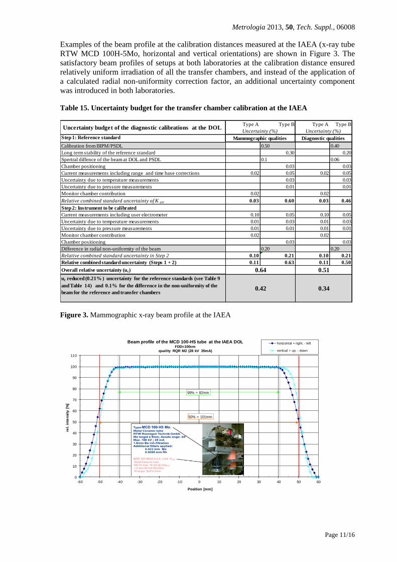
Examples of the beam profile at the calibration distances measured at the IAEA (x-ray tube
RTW MCD 100H-5Mo, horizontal and vertical orientations) are shown in Figure 3. The
satisfactory beam profiles of setups at both laboratories at the calibration distance ensured
relatively uniform irradiation of all the transfer chambers, and instead of the application of
a calculated radial non-uniformity correction factor, an additional uncertainty component
was introduced in both laboratories.
Table 15. Uncertainty budget for the transfer chamber calibration at the IAEA
Type A Type B Type A Type B
Uncertainty (%) Uncertainty (%)
Step 1: Reference standard Mammographic qualities
Calibration from BIPM/PSDL 0.50 0.40
Long term stability of the reference standard 0.30 0.20
Spertral diffence of the beam at DOL and PSDL 0.1 0.06
Chamber positioning 0.03 0.03
Current measurements including range and time base corrections 0.02 0.05 0.02 0.05
Uncertainty due to temperature measurements 0.03 0.03
Uncertainty due to pressure measurements 0.01 0.01
Monitor chamber contribution 0.02 0.02
Relative combined standard uncertainty of K air 0.03 0.60 0.03 0.46
Step 2: Instrument to be calibrated
Current measurements including user electrometer 0.10 0.05 0.10 0.05
Uncertainty due to temperature measurements 0.01 0.03 0.01 0.03
Uncertainty due to pressure measurements 0.01 0.01 0.01 0.01
Monitor chamber contribution 0.02 0.02
Chamber positioning 0.03 0.03
Difference in radial non-uniformity of the beam 0.20 0.20
Relative combined standard uncertainty in Step 2 0.10 0.21 0.10 0.21
Relative combined standard uncertainty (Steps 1 + 2) 0.11 0.63 0.11 0.50
Overall relative uncertainty (uc)
uc reduced (0.21% ) uncertainty for the reference standards (see Table 9
and Table 14) and 0.1% for the difference in the non-uniformity of the
beam for the reference and transfer chambers
Uncertainty budget of the diagnostic calibrations at the DOL
Diagnostic qualities
0.42 0.34
0.510.64
Figure 3. Mammographic x-ray beam profile at the IAEA
0
10
20
30
40
50
60
70
80
90
100
110
-60 -50 -40 -30 -20 -10 0 10 20 30 40 50 60
rel.
in
ten
sity
[%
]
Position [mm]
Beam profile of the MCD 100-H5 tube at the IAEA DOL FDD=100cm
quality RQR M2 (28 kV 35mA)
horizontal + right. - left
vertical + up. - down
50% = 101mm
99% = 82mm

Metrologia 2013, 50, Tech. Suppl., 06008
Page 12/16
5. Measurement results
The calibration coefficients were determined using the substitution method at both
laboratories, from a minimum of 3 repeated measurements using different setups at the
IAEA lab and with some beam qualities also repeated at the PTB. The reproducibility of
the calibration at the IAEA before and after the calibration at the PTB was estimated using
the standard deviation of the repeated measurements. It was typically less than 0.1 %. The
major part of this statistical uncertainty comes from the monitor chamber in the case of the
attenuated mammography qualities, where the measured currents were the lowest. The
calibration coefficients of the transfer chamber were also calculated without normalizing
the measured currents to the monitor chamber and the results were the same within 0.05 %
for all beam qualities. The leakage currents of the transfer chambers never exceeded 0.2 %
of the measured currents at both laboratories, and were subtracted in each case.
The slight differences in the HVL values of the same radiation qualities at the two
laboratories can be addressed through the application of suitable correction factors, kQ.[9]
Although these small kQ factor have been calculated for the PTB values by interpolation of
the energy response curves of the four transfer chambers (and can be seen in Tables 16-19
when they are larger than 0.02 %), they were applied only that six cases (bold numbers in
the tables) when the abs(1- kQ ) was higher than the estimated uncertainty of the kQ values.
The calibration coefficient of the transfer chambers determined at the PTB and IAEA and
their ratios are given in Tables 16-19.
Table 16. Calibration coefficients of the Extradin A3 #XR071832 chambers
Beam
qualitykQ
PTB
NKair
(mGy/nC)
IAEA
NKair
(mGy/nC)
PTB/IAEA
RQR-2 0.9998 8.1331 8.1011 1.0040
RQR-5 `-- 8.0320 8.0276 1.0005
RQR-10 `-- 8.0590 8.0489 1.0013
RQT-9 `-- 8.0930 8.0897 1.0004
Table 17. Calibration coefficients of the Extradin A4 #XP072344 chamber
Beam
qualitykQ
PTB
NKair
(mGy/nC)
IAEA
NKair
(mGy/nC)
PTB/IAEA
RQA-2 0.9984 0.9887 0.9918 0.9970
RQA-5 `-- 0.9797 0.9797 1.0000
RQA-10 `-- 0.9834 0.9809 1.0025

Metrologia 2013, 50, Tech. Suppl., 06008
Page 13/16
Table 18. Calibration coefficients of the Radcal RC6M #10183 chamber
Beam
qualitykQ
PTB
NKair
(mGy/nC)
IAEA
NKair
(mGy/nC)
PTB/IAEA
RQR-M1 0.9995 4.7790 4.7733 1.0012
RQR-M2 0.9995 4.7730 4.7711 1.0004
RQR-M3 0.9996 4.7720 4.7709 1.0002
RQR-M4 0.9997 4.7710 4.7698 1.0003
MMV-40 0.9996 4.7720 4.7733 0.9997
MMV-50 0.9999 4.7720 4.7742 0.9995
RQA-M2 1.0010 4.7640 4.7623 1.0003
MMH-40 1.0005 4.8070 4.7961 1.0023
MMH-50 1.0006 4.8210 4.8144 1.0014
MRV-28 `-- 4.7700 4.7701 1.0000
MRV-30 `-- 4.7680 4.7675 1.0001
MRV-35 `-- 4.7690 4.7691 1.0000
Table 19. Calibration coefficients of the Magna A650 #D121351 chamber
Beam
qualitykQ
PTB
NKair
(mGy/nC)
IAEA
NKair
(mGy/nC)
PTB/IAE
A
RQR-2 0.9996 7.6660 7.6634 1.0003
RQR-5 `-- 7.6787 7.6791 0.9999
RQR-10 0.9992 7.5780 7.5748 1.0004
RQT-9 `-- 7.5620 7.5773 0.9980
RQR-M1 0.9978 7.9369 7.9348 1.0003
RQR-M2 0.9985 7.9114 7.9230 0.9985
RQR-M3 0.9983 7.8978 7.9089 0.9986
RQR-M4 0.9983 7.8768 7.8892 0.9984
MMV-40 0.9983 7.8654 7.8749 0.9988
MMV-50 0.9993 7.8620 7.8656 0.9995
RQA-M2 0.9991 7.7750 7.7507 1.0031
MMH-40 `-- 7.7450 7.7142 1.0040
MMH-50 `-- 7.7450 7.7148 1.0039
MRV-28 `-- 7.8880 7.8847 1.0004
MRV-30 `-- 7.8790 7.8787 1.0000
MRV-35 `-- 7.8620 7.8644 0.9997

Metrologia 2013, 50, Tech. Suppl., 06008
Page 14/16
6. Results and discussion
6.1 Uncertainty of the comparison
The reference ionization chambers of the IAEA are traceable to the primary standards of
the PTB. Therefore, the uncertainties associated with the physical constants and the
correction factors of the free air chambers do not contribute to the uncertainty in the
comparison of the calibration coefficients determined at the PTB and the IAEA. If these
uncertainties are omitted, the relative uncertainties of the calibration coefficients
determined at the PTB reduce to 0.21 % according to the budgets given in Tables 9 and 14,
and those of the IAEA reduce to 0.42 % and 0.34 % for mammographic and diagnostic
qualities, respectively, according to the budgets given in Table 15. Quadratic summation of
the components leads to the combined standard uncertainties of the comparison of 0.47 %
and 0.40 % for mammographic and diagnostic qualities, respectively. These values are
summarized in Table 20.
Table 20. Relative standard uncertainties (in %) associated with the ratio of the calibration
factors obtained at PTB and IAEA
Source of uncertainty Mammo-
graphic General
diagnostic u(NK) PTB (without constants) 0.21 0.21 u(NK) IAEA (without reference) 0.42 0.34 Combined standard uncertainty 0.47 0.40
6.2 Final results of the comparison
The final results of the comparison were calculated as the average ratios of the PTB and
IAEA calibration coefficients obtained with the different transfer chambers and are given in
Table 21. It can be concluded that level of agreement of the calibration coefficients of both
laboratories is well within the relative standard uncertainty of the comparison of about
0.47 %.

Metrologia 2013, 50, Tech. Suppl., 06008
Page 15/16
Table 21 Final ratio of the PTB and IAEA calibration coefficients calculated as the
average of the transfer chambers applied.
Quality code
(IEC 61267)
Tube voltage
(kV)
PTB/IAEA
1 RQR-2 40 1.0021
2 RQR-5 70 1.0002
3 RQR-10 150 1.0008
4 RQA-2 40 0.9970
5 RQA-5 70 1.0000
6 RQA-10 150 1.0025
7 RQT-9 120 0.9992
8 RQR-M1 25 1.0008
9 RQR-M2 28 0.9995
10 RQR-M3 30 0.9994
11 RQR-M4 35 0.9994
12 *MMV-40 40 0.9991
13 *MMV-50 50 0.9995
14 RQA-M2 28 1.0017
15 *MMH-40 40 1.0031
16 *MMH-50 50 1.0026
17 *MRV-28 28 1.0002
18 *MRV-30 30 1.0001
19 *MRV-35 35 0.9998
*PTB code
7. Conclusions
The air kerma calibration coefficients of a set of four transfer ionization chambers were
determined at the PTB and the IAEA for 19 selected radiation qualities as used in
mammography and general diagnostic radiology. Due to the fact that the IAEA reference
standards are traceable to the primary standards of the PTB, correlations had to be taken
into account in the evaluation of the standard uncertainty of the comparison results, taken
as the ratio of calibration coefficients PTB/IAEA. It was estimated to be as low as about
0.4 %. The comparison results for the selected beam qualities were in the range (0.997-
1.0031) and were consistent within the uncertainty of the comparison. Taking into account
the flat energy response curves of the transfer chambers, the results for the remaining beam
qualities, not selected, would be expected to be within this 0.47 % relative standard
uncertainty, thus supporting all the relevant CMC claims of the IAEA.
8. References:
[1] J. Witzani1, H. Bjerke, F. Bochud, I. Csete, M. Denoziere, W. de Vries, K. Ennow, J. E.
Grindborg, C. Hourdakis, A. Kosunen, H. M. Kramer, F. Pernicka, T. Sander Calibration of
dosemeters used in mammography with different X ray qualities: Euromet Project No. 526
Radiation Protection Dosimetry 108:33-45 (2004)
[2] D. T. Burns, L. Büermann, H.-M. Kramer, B. Lange Comparison of the air-kerma
standards of the PTB and the BIPM in the low-energy x-ray range, 2001, Rapport BIPM-
01/08

Metrologia 2013, 50, Tech. Suppl., 06008
Page 16/16
[3] D. T. Burns, L. Büermann, H.-M. Kramer, B. Lange Comparison of the air-kerma
standards of the PTB and the BIPM in the medium-energy x-ray range, 2002, Rapport
BIPM-02/07
[4] C. Kessler, D.T. Burns, L. Büermann “Key Comparison BIPM.RI(I)-K7 of the air kerma
standards of the PTB, Germany and the BIPM in mammography X-rays” Metrologia, 2011,
48, tech. Suppl.,06011 http://www.bipm.org/utils/common/pdf/final_reports/RI/RI(I)-
K7/BIPM.RI(I)-K7_PTB_2010.pdf
[5] EURAMET.RI-S10, Technical Protocol
[6] CEI IEC 61267:2005-11 “Medical diagnostic X-ray equipment - Radiation conditions for
use in the determination of characteristics”
[7] ENGELKE B.-A., OETZMANN W., STRUPPEK, G., Die Meßeinrichtungen der Physikalisch-
Technischen Bundesanstalt zur Darstellung der Einheiten der Standard-Ionendosis,
Photonen-Äquivalentdosis und Luftkerma, PTB-Report Dos-16, 1988 (Physikalisch-
Technische Bundesanstalt, Braunschweig)
[8] ISO/IEC Guide to the Expression of Uncertainty of Measurement, JCGM 100:2008
[9] IAEA TRS 457 Dosimetry in Diagnostic Radiology: an International Code of Practice 2007