comparing the performance and accuracy of a...
TRANSCRIPT

Comparing the performance and accuracy of a pressure based and a density-based coupled solver Luca Mangani*, Wolfgang Sanz, Marwan Darwish,
ISROMAC 2016
International Symposium on
Transport Phenomena and
Dynamics of Rotating
Machinery
Hawaii, Honolulu
April 10-15, 2016
ABSTRACT
The velocity-pressure-density coupling algorithms that are at the core of computational fluid dynamics (CFD) methods can be grouped into two distinct groups: pressure-based and density-based methods. Pressure-based methods were originally developed for incompressible flows but have since been extended to address a wide range of flow conditions including compressible all speed flows. They are nowadays used in most commercial CFD codes both in their segregated and coupled form. Density-based methods, on the other hand, originated in the aeronautics industry for the simulation of compressible flows, and have thus been the dominant method used in the simulation of transonic and supersonic flows especially in aerodynamics applications. However, just as for pressure-based methods, a variety of techniques have over the years extended their ability to operate in low Mach and incompressible flow regimes. Turbomachinery applications is one area where competition between pressure-based and density-based solvers is still the norm in commercial, academic and open source codes, with both methods being used in diverse research groups and communities. While an extensive study would be required to clearly determine and evaluate the strength and weaknesses of these methods in this application area, the aim of this paper is to gain a better appreciation of the performance and accuracy of two state of the art codes, namely LINARS a density-based code developed at Graz University of Technology and coupledFoam, a pressure-based coupled solver developed on top of the OpenFOAMTM toolbox, noting that both solvers resolve the Navies Stokes equations in a coupled fashion.
Keywords Implicit Velocity-Pressure Coupling — Density-Based algorithms — Pressure-based Algorithms
*L. Mangani, Hydro and Fluid Mechanics Competence Centre, HSLU, Luzern, Switzerland W. Sanz, TTM, TU Graz, Graz, Austria M. Darwish, ME Department, AUB, Beirut, Lebanon
*Corresponding author: [email protected]
1. INTRODUCTION
Pressure-based solvers were originally developed in the 70’s [1] for the solution of low-speed incompressible flows on structured staggered grids, they were later extended in the 80’ and 90’s to solve compressible flows in the subsonic, transonic and supersonic regimes on unstructured collocated grids [2,3]. The modification was possible by changing the pressure equation from an elliptic form to a hyperbolic form with the addition of a pseudo-advection term that increases in strength with the Mach number [4,5,6]. Density-based solvers on the other hands have their applications mainly in the aeronautics industry and compressible flows [7,8,9,10]. Through the use of a variety of pre-conditioning techniques density-based methods have also been extended to operate over a wide range of flow conditions including low Mach number and incompressible flows [11]. The pre-conditioning results in the reformulation of the
density equation into some form of pressure equation.
In both families of methods the velocity field is computed from the momentum equations. In density-based solvers, the continuity equation is used to compute the density field while the pressure field is determined from the equation of state. In pressure-based solvers, the pressure field is computed by solving a pressure or pressure correction equation formulated from a combination of the continuity and momentum equations. The density field is then computed from the equation of state. Still an important distinction exists between the two families of methods in terms of the numerical approach used in each for the time linearization of the Navier-Stokes equations. In pressure-based methods, a SIMPLE [12] based algorithm is generally used to reformulate the continuity equation, while in density-based methods a Newton linearization is usually applied to the whole set of

equations. Details on each of these methods can be found in the literature [13,14]. The objective of this paper is to study the performance and accuracy of two state of the art codes [15,16] that use these two respective approaches, through the solution of a jet engine like turbine configuration, namely a high pressure transonic stator and a high pressure rotor. The two codes are first described, then the two test configurations are presented. This is followed by a comparison of the simulation results of the rotor test case wi th exper imental data. Final ly the convergence characteristics and computational times obtained from the two codes are discussed.
2. THE LINARS CODE
LINARS is the in-house CFD code developed at Graz University of Technology by Pecnik et al. [17]. Since then it has been the focus of continuous development that extended its applications with new models and increased its robustness and accuracy with new schemes and improved numerics. It has been successfully utilized for the solution of numerous applications [18,19,20,21]. The code solves the compressible Reynolds-averaged Navier-Stokes equations in conservative form by means of a fully-implicit time-marching finite-volume method. Structured grids are utilized in multi-block assignment. The inviscid fluxes are discretized with the upwind flux-difference splitting method of Roe [22]. A higher order of spatial accuracy for the convective fluxes is achieved through monotone upstream-centered schemes (MUSCL). Generally, a third-order spatial discretization is applied. In order to avoid numerical instabilities the total variation diminishing scheme (TVD) is applied. The TVD scheme switches to first order accuracy in regions of high state vector gradients. The viscid flux vector at the cell interfaces is constructed in a central-differencing manner after transformation using Green’s theorem. A linear set of algebraic equations is obtained by discretization in time with the Newton-Raphson procedure. The linearization of the inviscid fluxes is spatially of first order. The viscid fluxes are linearized with the thin-layer approximation to obtain a block tridiagonal matrix of the implicit side for each grid index line. The linear equation set is solved by the al ternat ing direct ion impl ic i t scheme. Convergence of steady state simulations is improved by using a local time step based on a local stability criterion and a multi-level multi-grid V-cycle. The main flow equations, the turbulence equations, and the transition equations are solved sequentially. For turbulence modeling the one-equation turbulence model by Spalart and Allmaras [23] (SA) and the two-equation shear stress transport (SST) model by Menter [24] were implemented. The
reader is referred to the cited references for details about the models. In order to consider boundary-layer transition the γ−Reθ correlation-based transition model by Menter et al. [25] with the modification introduced by Langtry and Menter [26] was implemented.
3. The coupledFoam CODE
coupledFoam is a fully coupled pressure-based solver implemented within the OpenFOAMTM
framework based on the fully coupled algorithms of Darwish et al. [29] that accounts for the pressure velocity coupling more comprehensively. Over the past few years new development in the solver has greatly improved its robustness and performance [27]. An implicit diffusion discretization [28] is now used for the pressure equation, while the Algebraic Multigrid linear solver (AMG) now boasts new features that greatly enhance its performance when dealing with ill-conditioned matrices that frequently arise in compressible flows. Finally the numerics of the turbulence equations has also experienced numerous improvements to ensure that the models cope with the rapidly converging velocity and pressure fields. The reader is referred to [29] for more details on the numerical discretization and velocity-pressure algorithm used in the coupled solver. Thus the discretized equations in any control volume resemble the pattern shown in Figure 1.
$
Figure 1. Coupled system of discretized equations at each finite volume The discretized equations representing the Navier-Stokes equations, in the case of LINARS are solved as one system of equations including now the energy equation.
4. TEST CASE DESCRIPTION
The selected test case is based on the two-stage transonic test turbine that is operated by the Institute for Thermal Turbomachinery and Machine Dynamics at Graz University of Technology for flow and acoustic investigations. It is a continuously operating two-stage cold-flow open-circuit plant. In Figure 2 the meridional flow path through the two-stage test turbine is plotted. The turbine consists of 24 high-pressure vanes, 36 un-shrouded HP rotor blades, 16 strut blades within an S-shaped turning mid-turbine frame (TMTF) and 72 shrouded low pressure rotor blades rotating in counter-clockwise direction. This design has been developed within the framework of the EU Project DREAM.
• ! ! !! • ! !! ! • !! ! ! •
⎡
⎣
⎢⎢⎢⎢
⎤
⎦
⎥⎥⎥⎥C
••••
⎡
⎣
⎢⎢⎢⎢
⎤
⎦
⎥⎥⎥⎥C
+
• !• !
• !! ! ! •
⎡
⎣
⎢⎢⎢⎢
⎤
⎦
⎥⎥⎥⎥NB
••••
⎡
⎣
⎢⎢⎢⎢
⎤
⎦
⎥⎥⎥⎥
NB∑
NB
=
••••
⎡
⎣
⎢⎢⎢⎢
⎤
⎦
⎥⎥⎥⎥C
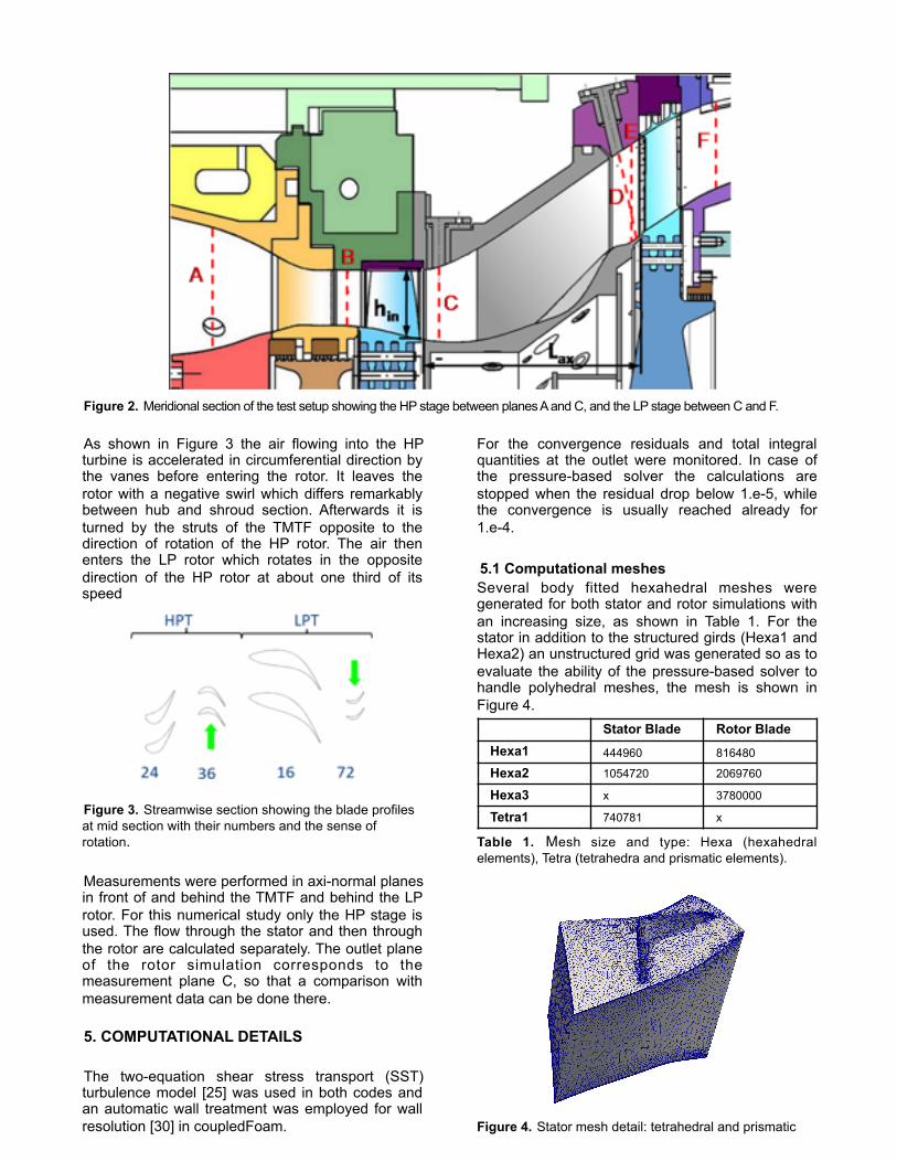
$ Figure 2. Meridional section of the test setup showing the HP stage between planes A and C, and the LP stage between C and F.
As shown in Figure 3 the air flowing into the HP turbine is accelerated in circumferential direction by the vanes before entering the rotor. It leaves the rotor with a negative swirl which differs remarkably between hub and shroud section. Afterwards it is turned by the struts of the TMTF opposite to the direction of rotation of the HP rotor. The air then enters the LP rotor which rotates in the opposite direction of the HP rotor at about one third of its speed
$ Figure 3. Streamwise section showing the blade profiles at mid section with their numbers and the sense of rotation.
Measurements were performed in axi-normal planes in front of and behind the TMTF and behind the LP rotor. For this numerical study only the HP stage is used. The flow through the stator and then through the rotor are calculated separately. The outlet plane of the rotor simulation corresponds to the measurement plane C, so that a comparison with measurement data can be done there.
5. COMPUTATIONAL DETAILS
The two-equation shear stress transport (SST) turbulence model [25] was used in both codes and an automatic wall treatment was employed for wall resolution [30] in coupledFoam.
For the convergence residuals and total integral quantities at the outlet were monitored. In case of the pressure-based solver the calculations are stopped when the residual drop below 1.e-5, while the convergence is usually reached already for 1.e-4.
5.1 Computational meshes Several body fitted hexahedral meshes were generated for both stator and rotor simulations with an increasing size, as shown in Table 1. For the stator in addition to the structured girds (Hexa1 and Hexa2) an unstructured grid was generated so as to evaluate the ability of the pressure-based solver to handle polyhedral meshes, the mesh is shown in Figure 4.
Table 1. Mesh size and type: Hexa (hexahedral elements), Tetra (tetrahedra and prismatic elements).
$ Figure 4. Stator mesh detail: tetrahedral and prismatic
Stator Blade Rotor BladeHexa1 444960 816480
Hexa2 1054720 2069760
Hexa3 x 3780000
Tetra1 740781 x

elements.
The three meshes of the rotor with increasing cell numbers consist of 8 blocks. Special emphasis has been laid on the generation of a smooth mesh in the tip gap, as shown in Figure 5, by adding here additional blocks. Clustering and refinement of the mesh close to the wall were adopted in order to achieve an average y+ of 1.
$
$ Figure 5. Rotor mesh detail: the tip gap is fully discretised.
5.2 Boundary conditions At the inlet of the stator constant values for total pressure, total temperature and flow angle as well as for the turbulent quantities are imposed. At the outlet the static pressure at a given radius is set assuming radial equilibrium. The non-reflecting boundary treatment according to Giles has been applied. At the inlet of the rotor a radial distribution of the boundary values has been imposed taken from a former full stage simulation where the flow quantities were extracted at the interface. Again a radial equilibrium static pressure profile was imposed at the outflow. Periodicity boundary conditions were adopted in order to reduce memory and computational time and to capture the influence of the flow in the pitch-wise direction. A no slip and adiabatic conditions were applied to the walls.
6. RESULTS AND DISCUSSION
6.1 Stator blade
For the stator blade simulation, LINARS and coupledFoam were used with meshes Hexa1, Hexa2 and only coupledFoam for mesh Tetra1. For the stator blade simulation no experimental measurements are available and than comparisons are limited to the CFD results between both codes.
The coupledFoam code use a false transient formulat ion with a physical t imestep that corresponds to a mean Courant number (CFL) of 300 and a maximum of 10000. LINARS instead use a local CFL of 10. An interesting aspect that was investigated is the scalability with mesh size of coupledFoam, that is the convergence characteristics of the solver with increasing mesh size. As demonstrated in [16], coupledFoam is mesh scalable when applied to steady state incompressible flow simulations, that is it requires a nearly constant number of iterations to converge independently of mesh size. For compressible and turbulent flows the additional couplings resulting from the energy equation are not implicitly accounted for, resulting in a slight deterioration of the scaling behaviour. The scalability can be assessed in Figure 6 were the convergence residuals for coupledFoam is shown for the three meshes Hexa1, Hexa2 and Tetra1 meshes. As can be seen from the converge plots the simulations converge in roughly the same number of iterations indicating excellent scalability of coupledFoam for this type of flow problems. For LINARS the CPU time requested was about 40 sec per iteration with an overall dropping of the residual of 4 order of magnitude in 2000 iterations.
$ (a)
$ (b)
1e-06
1e-05
0.0001
0.001
0.01
0.1
1
0 10 20 30 40 50 60 70 80 90 100 110
Res
idua
ls [-
]
Number of iterations [-]
Hexa 1: Number of iterations vs. Residuals
Pressure Based pPressure Based UxPressure Based UyPressure Based Uz
mass-Imbalance%/100
1e-06
1e-05
0.0001
0.001
0.01
0.1
1
0 10 20 30 40 50 60 70 80 90 100 110
Res
idua
ls [-
]
Number of iterations [-]
Hexa 2: Number of iterations vs. Residuals
Pressure Based pPressure Based UxPressure Based UyPressure Based Uz
mass-Imbalance%/100

$ (c) Figure 6. Residuals and mass imbalance convergence for the pressure-based solver.
Table 2 shows some difference in the results obtained from LINARS and coupledFoam for Hexa2 Mesh. The results pertain to pressure losses and Mass flux error with LINARS yielding a higher pressure loss and higher Mass Flow error.
Table 2. Total pressure losses and Mass flow percentage error
However as shown in Figure 7 and Figure 8 which depicts contour plots of static pressure at the blade, overall results from LINARS and CoupledFoam are comparable. At the pressure side (Figure 7) both codes predict a strong deceleration at the leading edge region before the pressure remains nearly constant. On the suction side (Figure 8) a strong acceleration occurs up to about 70 % chord length before a strong pressure increase (dark blue zone at the hub) is caused by a shock. Both codes predicts similar expansion of the fluid with slightly differences in the shock region. The shock is predicted in the same axial position with a bigger pick in coupledFoam but with a general smoother behaviour.
$ $ (a) (b) Figure 7. Pressure side static pressure contour map: (a) coupledFoam upper, (b) LINARS.
$ $ (a) (b) Figure 8. Suction side static pressure contour map a) coupledFoam, b) LINARS
The tendency to a smooth solution is also evident in the total pressure contour maps at the outlet as shown in Figure 9. The boundary layers at the shroud are similar, but at the hub LINARS predicts a more pronounced zone of low pressure. The overall accuracy and agreement of both codes are quite good bearing in mind the different algorithms used for the pressure-velocity coupling, and can be due to the difference in the used discretization advection schemes.
$
$ (a) (b) Figure 9. Outlet total pressure contour map: (a) coupledFoam, (b) LINARS.
6.2 Rotor blade
The HP rotor was simulated as a standalone blade with appropriate radial profiles at the inlet based on a previous full stage simulation with a mixing plane interface performed in LINARS. Similar to the stator blade, the coupledFoam code use a false transient formulat ion with a physical t imestep that corresponds to a mean Courant number (CFL) of 300 and a maximum of 10000. LINARS instead use a local CFL of 10. For this case experimental data were available in terms of circumferentially
1e-06
1e-05
0.0001
0.001
0.01
0.1
1
0 10 20 30 40 50 60 70 80 90 100 110
Res
idua
ls [-
]
Number of iterations [-]
Tetra1: Number of iterations vs. Residuals
Pressure Based pPressure Based UxPressure Based UyPressure Based Uz
mass-Imbalance%/100
Pressure Losses (%)
Mass Flow Error (%)
coupledFoam -3.78 0.016
LINARS -4.16 0.318

averaged profiles downstream the rotor blade corresponding to the section C in Figure 2. Pitch and yaw angles, as well as axial and circumferential absolute velocity profiles were plotted against experimental results.
Scalability Analysis In the rotor simulation three hexahedral meshes, denoted by Hexa1, Hexa2 and Hexa3 were used for the linear convergence analysis of coupledFoam. Figure 10 shows that even for a moving reference frame the linear scalability of the coupledFoam solver is retained. For these runs the convergence of the mass average total temperature at the outlet was monitored. This approach is sometimes used to ensure that the simulation is fully converged. In Figure 10, the convergence characteristics for the HEX1, HEXA2 and HEXA3 meshes are shown, for all three meshes the total temperature solution converged within 50 iterations, i.e equivalent for a residual valour of 1.0e-4, this was similarly observed in other simulations [16]. Furthermore, the convergence characteristics of the three meshes are nearly identical, which indicates that the solver is all scaling linearly with the mesh size.
Accuracy Analysis Table 3 shows the Rotor performance as computed with LINARS and coupledFoam for Hexa2 Mesh. Results for Hexa3 and Hexa1 were similar. Results of both solvers are very similar with the coupledFoam yielding a slightly higher value for Rotor performance and a lower Mass flow Error. Calculated and measured circumferential averaged profiles for both LINARS and coupledFoam, are shown in Figure 11. The general agreement is quite good for all the quantities.It is interesting that coupledFoam predicts most secondary effects to be closer to the shroud. This is especially evident for the tip leakage flow where coupledFoam gives a higher axial velocity peak closer to the shroud. The higher peak agrees better with the measurements whereas its location is better captured by LINARS.
$
$
! Figure 10. Residuals, total temperature and mass imbalance convergence for the pressure-based solver
The discrepancies between computed and experimental results can be partly explained by the steady simulation of the very unsteady flow and by the missing interaction with the following TMTF and LP stage. A full unsteady simulation of the entire test rig should be the focus of future work.
Table 3. Rotor Performance and Mass flow percentage error.
$ (a)
1e-06
1e-05
1e-04
1e-03
1e-02
1e-01
1e+00
0 10 20 30 40 50 60 70 80 90 100 110
Res
idua
ls [-
]
Number of iterations [-]
Hexa 1: Number of iterations vs. Residuals and Outlet Total Temperature
Pressure Based pPressure Based UxPressure Based UyPressure Based Uz
mass-Imbalance%/100
320 340 360 380 400 420 440 460
0 20 40 60 80 100Iterations
T0 Outlet [K]
1e-06
1e-05
1e-04
1e-03
1e-02
1e-01
1e+00
0 10 20 30 40 50 60 70 80 90 100 110
Res
idua
ls [-
]
Number of iterations [-]
Hexa 3: Number of iterations vs. Residuals and Outlet Total Temperature
Pressure Based pPressure Based UxPressure Based UyPressure Based Uz
mass-Imbalance%/100
320 340 360 380 400 420 440 460 480
0 20 40 60 80 100Iterations
T0 Outlet [K]
Efficiency (%)Mass Flow Error (%)
coupledFoam 94.47 -0.00139
LINARS 93.69 -0.200
-1
-0.75
-0.5
-0.25
0
0.25
0.5
0.75
1
0 0.1 0.2 0.3 0.4 0.5 0.6 0.7 0.8 0.9 1
Circ
umfe
rent
ial V
eloc
ity [-
]
Normalized spanwise [-]
Circumferential Velocity Profile
ExpcoupledFoam
LINARS

$ (b)
$ (c)
$ (d) Figure 11. Circumferential averaged flow profiles at the outflow plane
7. CONCLUSIONS
Simulations on the stator and the rotor of the high pressure stage were performed using two codes with different numerics, one using a pressure-based method, coupledFoam and the other using a density-based method, LINARS. Results from both codes were shown to be very similar and more importantly it was shown that computed results were comparable to experimental data. Difference between the computed results of the two codes could be easily attributed to difference in the advection schemes used rather that to the adopted algorithmic method, especially for shocks resolving. Evidence can be found for the outlet total pressure counters shown in figures 7, 8 and 9 for the stator case. This issue will be investigated in future work through the use of similar schemes for the discretization of diffusion and advection terms. A scalabi l i ty s tudy was a lso conducted on coupledFoam, results indicate that for this class of problems the coupled pressure-based solver retains very good scalabi l i ty with mesh size, as
demonstrated by the near constant number of iterations to convergence attained on multiple mesh sizes. A similar study will be performed on the density-based solver in future work.
ACKNOWLEDGMENTS
The authors wish to acknowledge the support received from their respective Universities, HSLU Luzern, TUGraz and AUB.
REFERENCES
[1] S.V. Patankar and D.B. Spalding, A Calculation Procedure for Heat, Mass and Momentum Transfer in Three-Dimensional Parabolic Flows, International Journal of Heat and Mass Transfer, 15:1787-1806, 1972. [2] F. Moukalled and M. Darwish, A Unified Formulation of the Segregated Class of Algorithms for Fluid Flow at All Speeds, Numerical Heat Transfer, Part B: Fundamentals, 37:103-139, 2000. [3] I. Demirdzic, Z. Lilek, M. Peric, Collocated Finite Volume Method for Predicting Flows at All Speeds, Int. J. Num. Methods Fluids, 16:1029-1050, 1993. [4] H. Bijl and P. Wesseling, A Unified Method for Computing Incompressible and Compressible Flows in Boundary-Fitted Coordinates, J. Comput. Physics,141:153–173, 1998. [5] G. Burgree, Studies of Pressure-Velocity Coupling Schemes for Analysis of Incompressible and Compressible Flows, Phd Thesis, The University of Alabama, Huntsville, 1987 [6] R. Issa, D. Gosman, P. Watkins The Computation of Compressible and Incompressible Recirculating Flows by a Non-iterative Implicit Scheme, J. Comput. Physics, 62:66-82, 1986 [7] SK. Godunov, A difference scheme for numerical computation of discontinuous solution of hyperbolic equation. Matematicheskii Sbornik 1959; 47:271–306. [8] P.D. Lax, B. Wendroff, Systems of conservation laws. Communications on Pure and Applied Mathematics 1960; 13(2):217–237. [9] C.M. Hung, R.W. McCormick, Numerical Solutions of Supersonic and Hypersonic Laminar Compression Corner Flows, AIAA Journal, 14:475-481, 1978 [10] R.W. MacCormack R.W., A numerical method for solving the equation of compressible viscous flow, AIAA journal, 1275-1281, 1982 [11] Y.H Choi and C.L. Merkle, The application of preconditioning in viscous flows, J. Comput. Physics, 105:207-223, 1993.
-0.6
-0.5
-0.4
-0.3
-0.2
-0.1
0
0.1
0.2
0.3
0.4
0 0.1 0.2 0.3 0.4 0.5 0.6 0.7 0.8 0.9 1
Yaw
[-]
Normalized spanwise [-]
Yaw Angle Profile
ExpcoupledFoam
LINARS
0
0.1
0.2
0.3
0.4
0.5
0.6
0.7
0.8
0.9
1
0 0.1 0.2 0.3 0.4 0.5 0.6 0.7 0.8 0.9 1
Axia
l Vel
ocity
[-]
Normalized spanwise [-]
Axial Velocity Profile
ExpcoupledFoam
LINARS
-0.4
-0.3
-0.2
-0.1
0
0.1
0.2
0.3
0.4
0.5
0.6
0.7
0 0.1 0.2 0.3 0.4 0.5 0.6 0.7 0.8 0.9 1
Pitc
h [-]
Normalized spanwise [-]
Pitch Angle Profile
ExpcoupledFoam
LINARS

[12] F. Moukalled, M. Darwish, A High Resolution Pressure-Based Algorithm for Multiphase Flow at all Speeds, J. Comput. Phys., vol. 168, No 1, pp 101-133, 2002. [13] C. Hirsch, Numerical Computation of Internal and External Flows, Vol. 1 and 2. John Wiley and Sons: New York, 1988. [14] F. Moukalled, L. Mangani, M. Darwish, The Finite Volume Method in Computational Fluid Dynamics: an Advanced Introduction with OpenFOAMTM and Matlab, Springer, 2015 [15] P. Bader, W. Sanz , Steady and Unsteady CFD Calculation of the Laminar ago Turbulent Transition in a Turning mid Turbine Frame with Embedded Design, Proceedings of ASME Turbo Expo 2015: Turbine Technical Conference and Exposition, Montréal, Canada, June 15 – 19, 2015 [16] L. Mangani, M. Darwish and F. Moukalled, “Development of a Pressure-Based Coupled CFD Solver for Turbulent and Compressible Flows in Turbo-Machinery Applications”, J. Numerical Heat Transfer, in print, 2015 [17] R. Pecnik, P. Pieringer and W. Sanz, Numerical Investigation of the Secondary Flow of a Transonic Turbine Stage Using various Turbulence Closures, paper GT2005-68754 in Proceedings of GT 2005 ASME Turbo Expo 2005: Power for Land, Sea and Air, Reno-Tahoe, Nevada, USA, June 2005 [18] W. Sanz, Kelterer, M., Pecnik, R., Marn, A., Göttlich, E., Numerical investigation of the effect of tip leakage flow on an aggressive S-shaped intermediate turbine duct, Proceedings of the ASME Turbo Expo, ASME Turbo Expo; Orlando, FL; United States; June 8-12, 7:905-915, 2009 [19] P. Bader, W. Sanz, R. Spataro, E. Göttlich, Flow evolution through a Turning Mid Turbine Frame with embedded design, Proceedings of the ASME Turbo Expo Volume 2C, 2014, ASME Turbo Expo 2014: Turbine Technical Conference and Exposition, GT 2014; Dusseldorf; Germany; June 16-20 2014 [20] S.Vader, P., Sanz, W., Spataroy, R., Unsteady CFD simulation of a turning mid turbine frame with embedded design, 11th European Conference on Tu r b o m a c h i n e r y F l u i d D y n a m i c s a n d Thermodynamics, ETC 2015; Technical University of Madrid, Madrid; Spain; March 23 -27 2015 [21] C. Heschl, C., K. Inthavong, W. Sanz, J. Tu, Evaluation and improvements of RANS turbulence models for linear diffuser flows, Computers and Fluids, 71:272-282, 2013 [22] P.L. Roe, P.L., “Approximate Riemann Solvers, Parameter Vectors, and Difference Schemes”, J. of Compute. Physics, 43:357-372, 1981 [23] P.R. Spalart and S.R. Allmaras, A One-Equation Turbulence Model for Aerodynamic Flows,
Recherche Aerospatiale, 1:5-21, 1994 [24] F.R. Menter, "Two-Equation Eddy-Viscosity Turbulence Models for Engineering Applications," AIAA Journal, 32:1598-1605, 1994 [25] F.R. Menter, R.B. Langtry, S.R. Likki, Y.B. Suzen, P.G. Huang, S. Völker, A correlation based transition model using local variables part 1 – model formulation. In: ASME-GT2004-53452, ASME TURBO EXPO 2004, Vienna, Austria, 2004 [26] R.B. Langtry, F.R. Menter, Transition Modeling for General CFD Applications in Aeronautics, AIAA Paper 2005-522, Reno, Nevada, 2005 [27] L. Mangani, M. Darwish, “Development of a Pressure-based coupled CFD solver for Turbulent and Compressible Flows”, 9th International OpenFOAMTM Workshop , Zagreb Croat ia, June16-19, 2014. [28] K. Lipnikov, D. Svyatskiy, and Yu. Vassilevski, Minimal stencil finite volume scheme with the discrete maximum principle , Russ. J. Numer. Anal. Math. Modelling, 27:369–385, 2012 [29] M. Darwish and F. Moukalled, “A Fully Coupled Navier-Stokes Solver for Fluid Flow at All Speeds”, Num. Heat Transfer, part B: Fundamentals, 45:410–444, 2014 [30] F.R. Menter, “Zonal Two Equation Turbulence Model For Aerodynamic Flows” . AIAA Paper (93-2906), 1993