comparative study of traditional devices and facts
TRANSCRIPT
Comparative Study of Traditional Devices and FACTS Controller for Enhancing the Transient Stability Margin
WaseemAslam1*, Yonghai Xu1, Abubakar Siddique1, M. Nadeem Aslam2, M. Kaleem Aslam2
1 School of Electrical & Electronics Engineering, North China Electric Power University (NCEPU), Beijing, China. 2 Department of Electrical Engineering, Institute of Southern Punjab (ISP), Pakistan. * Corresponding author. Tel.: +8613051635933; email: [email protected] Manuscript submitted February 14, 2018; accepted May 8, 2018. doi: 10.17706/ijcee.2018.10.3.213-220
Abstract: Instead of transmission lines expansion or building new substations in our present transmission
system, the proper installation of FACTS (Flexible AC Transmission Systems) seems to be a promising
strategy to support transient stability and increasing power demand. This paper narrates a correlative
performance of traditional devices (AVR, TG, and PSS) with series FACTS controller on electric power network.
Here, IEEE-14 bus system is considered to be the benchmark of the power network. This proposed approach
is implemented with the power system analysis toolkit (PSAT) software and is applied to small case studies,
IEEE 14-Bus. For the performance analysis the Eigen value analysis and time domain simulation results are
compared for result validation. Results revealed that FACTS controller improve better stability as compared to
other conventional used devices.
Key words: FACTS, TCSC controller, PSS, PSAT, steady state stability.
1. Introduction
In today's world, power demand is increasing significantly over the last few decades. This growing power
demand, after all does not pursued by expansion in power generation and transmission capacity.
Consequently, in order to fulfill the growing electric load requirement, power plants are operating at their
maximum capacity [1]. Furthermore, transmission lines are also operating nearer to their thermal limits. So,
the power systems are seemly less protected and ever awaiting the exposure of voltage instability which has
led to many major network collapses world-wide. It was revealed that voltage instability was one of the major
cause for the North American blackout in August 2003 [2].
The major reason of voltage instability perhaps by reason of inadequacy of reactive capacity of power
system while interruptions like line outage contingencies. To maintain security of power systems, it is
important to suggest relevant measures to enhance power system security and maximize voltage stability
margins. Different preventive measures like appropriately rescheduling of generation and energy transfer,
bringing backup generators in line, load shedding and VAR control by using series or shunt capacitors are
taken up to conquered voltage instability controversy. The traditional sources of reactive power are not quick
responses for the need of the reactive power of the power network. Also most of them are the
electromechanical controller which got the disadvantages like slowness and wear [3].
Voltage stability can be classified into two sections particularly dynamic and static. The static voltage
International Journal of Computer Electrical Engineering
213 Volume 10, Number 3, September 2018

stability approaches are primarily relying on steady state model in the tests like the flow of power model [4].
Dynamic stability analysis presents the utilization of a model identified by nonlinear differential and algebraic
equations comprises dynamics of generators, regulating transformers etc. A lot of approaches have been
employed in static voltage stability analysis like the P-V and Q-V curves, model analysis, artificial neural
networks [4]. Line stability index (LSI) gives essential knowledge to find the critical line and closeness of the
network to voltage instability in the power system.
The new improvements and application of Flexible Alternating Current transmission system in the
extended amount of power transmission network has been employed in large applications. These devices
enhances the voltage and angle stability. A lot of specific static and dynamic models have been suggested to
shows the FACTS analysis performance in network [5]. This paper describes the utilization of FACTS device
TCSC (Thyristor Controlled Series Compensator). Thyristor controlled series compensators are connected in
series with the power transmission lines [6]. TCSC provides continuous variable capacitive reactance that
can give regularly control of power on the AC transmission line over the wide range. TCSC perhaps an
individual big unit, or may subsist many same or various sized smaller capacitors for giving better
performance [7]. Due to the considerable cost of TCSC, it is worthwhile to determine the suitable placement
of thyristor controlled series Compensator in a power network to gain maximal merits [8]. The suitable
placement of TCSC has been elected on the ground of line stability index (LSI) for enhancement of voltage
stability of power network.
The remaining paper is proceeded as: Section 2 describes operating principle of TCSC. A description of
Schematic Control system of TCSC is shown in Section 3. Section 4 describes the elected analysis case IEEE
14 bus system and software tool. Section 5, describes the results and discussion.
2. Operating Principle of TCSC
TCSC is a series compensating FACTS device. TCSC consists of a series capacitor bank shunted by TCR
(Thyristor Controlled Reactor). The power flow in a particular branch may be controlled by operating the
TCSC either in inductive or capacitive mode by increasing or decreasing the line reactance. It is modeled
with variable series reactance. The structure of TCSC is given in Fig. 1, where XL and XC indicate inductive
reactance and capacitive reactance. The current entering the capacitor branch is denoted as iC and the
current entering the TCR branch is denoted as iL and the total current entering the TCSC module is iT.
TCSC can be governed to perform in both capacitive and inductive fashions averting steady state
resonance [8], as described in below Fig. 2.
Fig. 1. Basic scheme of TCSC.
Fig. 2. Impedance characteristics of TCSC.
International Journal of Computer Electrical Engineering
214 Volume 10, Number 3, September 2018

Thus, impedance characteristics of TCSC (XTCSC) shows, both capacitive and inductive operating ranges
are possible though different values of delay angle (α):
Blocking mode
In this mode the thyristors are not gated and hence they can be operated as a fixed capacitor. In this
fashion αL lim and αC lim.
Thyristor valve by pass mode
In this fashion thyristors are gated for full conduction such that TCSC reactance is parallel combination of
a fixed capacitor and fixed inductor. This is called inductive operation zone.
Vernier control mode(Capacitive zone)
The thyristors are continuously gated to run in capacitive zone operation. In this fashion angle vary as αL
lim to 180°.
3. Control System of TCSC
To achieve different control objectives a layered structure in the controller is used. The control scheme of
TCSC denoted in Fig. 3, subsist of following control approaches.
Fig. 3. Control scheme of TCSC.
3.1. Control Modes Inner control algorithm
Frequency components below 40 Hz cause the torsional vibrations in generator shafts due to which
deviations in the injected current are introduced. These deviations change the apparent impedance.
Therefore TCSC has to make immune to the SSR this is possible by designing the inner loop so that the
probable impedance of the TCSC becomes resistive-inductive in the total sub-synchronous frequency range.
By accomplishing so, no electrical resonance can appear between the transmission line and the TCSC.
Reactance control at fN
This second layer of control system is introduced to make sure that TCSC does not operate in inductive
mode near the rated frequency.
System related control
The third layer of control system is used to control the probable reactance of the TCSC at network
frequency. By doing this performance of the system can be improved by providing additional damping to
electromechanical oscillation. By using this control scheme it can be impermanent rises the amount of
compensation of a line in place of pacifying the voltage drops at nodes that do not have plentiful reactive
power support in the event of emergencies.
International Journal of Computer Electrical Engineering
215 Volume 10, Number 3, September 2018

4. Simulation Model
Fig. 4. System with AVR and TG installed.
Fig. 5. System with PSS installed.
International Journal of Computer Electrical Engineering
216 Volume 10, Number 3, September 2018

5. Results and Discussion
In this work the results got from simulation for proposed systems are presented. From the Fig. 6, it can
be seen that there are no disturbances in the system but the system becomes unstable after some time. The
Eigen value analysis shows that the system is steady state unstable with 2 positive Eigen values and hence
the system parameters develop oscillations after some time. From Fig. 7, (a), (b), and (c) it can be evaluated
that with only AVR installed, the time domain simulations show sustained oscillations.
Fig. 6. Eigen value analysis of 14 bus system.
Fig. 7. (a) Speeds of generator 1 and generator 2. (b) Power of generator 1 and 2. (c) Voltages of system with
AVR only.
Fig. 8. Eigen value analysis for system with TG installed.
Fig. 9. (a) Generator power with TG installed. (b) Generator speeds with TG installed. (c) Voltages with TG
installed.
International Journal of Computer Electrical Engineering
217 Volume 10, Number 3, September 2018

From Fig. 8, it can be seen that with Turbine Governor (TG) installed there are no positive Eigen values
and the system is steady state stable for no disturbances. The time domain simulation results with TG
installed in proposed system are shown in Fig. 9 (a), (b), and (c).
5.1. Results for Transient Stability without TCSC
Fig. 10. Unstable due to line outage.
Fig. 11. (a) Power of generators. (b) Generator speeds after line outage. (c) Voltages of generators after line
outage.
Now in the same system when a line24 is outage the system becomes unstable. Initially the system was
stable but after line outage at t=1 seconds the system becomes unstable. From the Fig. 10, it can be seen
that without TCSC installed, there are two positive Eigen values of the excitation of generator 1 indicating
that the system has become unstable following a line outage.
From the Fig. 11 (a), (b), and (c) it can be seen that, without TCSC installed in the test system the time
domain simulations indicating that the system has become unstable following a line outage.
5.2. Results for Transient Stability with TCSC
From Fig. 13 (a), (b), and (c) time domain simulation results shows that, after TCSC inserted (Fig. 12)
between bus 1 and 5 the system becomes stable even for line contingency.
Fig. 12. Eigen value analysis with TCSC.
International Journal of Computer Electrical Engineering
218 Volume 10, Number 3, September 2018
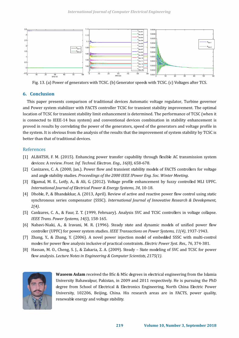
Fig. 13. (a) Power of generators with TCSC. (b) Generator speeds with TCSC. (c) Voltages after TCS.
6. Conclusion
This paper presents comparison of traditional devices Automatic voltage regulator, Turbine governor
and Power system stabilizer with FACTS controller TCSC for transient stability improvement. The optimal
location of TCSC for transient stability limit enhancement is determined. The performance of TCSC (when it
is connected to IEEE-14 bus system) and conventional devices combination in stability enhancement is
proved in results by correlating the power of the generators, speed of the generators and voltage profile in
the system. It is obvious from the analysis of the results that the improvement of system stability by TCSC is
better than that of traditional devices.
References
[1] ALBATSH, F. M. (2015). Enhancing power transfer capability through flexible AC transmission system
devices: A review. Front. Inf. Technol. Electron. Eng., 16(8), 658-678.
[2] Canizares, C. A. (2000, Jan.). Power flow and transient stability models of FACTS controllers for voltage
and angle stability studies. Proceedings of the 2000 IEEE IPower Eng. Soc. Winter Meeting.
[3] Elgamal, M. E., Lotfy, A., & Ali, G. (2012). Voltage profile enhancement by fuzzy controlled MLI UPFC.
International Journal of Electrical Power & Energy Systems, 34, 10-18.
[4] Dhoble, P., & Bhandakkar, A. (2013, April). Review of active and reactive power flow control using static
synchronous series compensator (SSSC). International Journal of Innovative Research & Development,
2(4).
[5] Canlzares, C. A., & Faur, Z. T. (1999, February). Analysis SVC and TCSC controllers in voltage collapse.
IEEE Trans. Power Systems, 14(I), 158-165.
[6] Nabavi-Niaki, A., & Iravani, M. R. (1996). Steady state and dynamic models of unified power flow
controller (UPFC) for power system studies. IEEE Transactions on Power Systems, 11(4), 1937-1943.
[7] Zhang, Y., & Zhang, Y. (2006). A novel power injection model of embedded SSSC with multi-control
modes for power flow analysis inclusive of practical constraints. Electric Power Syst. Res., 76, 374-381.
[8] Hassan, M. O., Cheng, S. J., & Zakaria, Z. A. (2009). Steady – State modeling of SVC and TCSC for power
flow analysis. Lecture Notes in Engineering & Computer Scientists, 2175(1).
Waseem Aslam received the BSc & MSc degrees in electrical engineering from the Islamia
University Bahawalpur, Pakistan, in 2009 and 2011 respectively. He is pursuing the PhD
degree from School of Electrical & Electronics Engineering, North China Electric Power
University, 102206, Beijing, China. His research areas are in FACTS, power quality,
renewable energy and voltage stability.
International Journal of Computer Electrical Engineering
219 Volume 10, Number 3, September 2018

Yonghai Xu was born in April 1966. In 1989, he got the bachelor's degree of engineering
from Tsinghua University. In 1992, he got the degree of master of engineering from North
China Electric Power Institute. In 2002, he got the degree of doctor of engineering from
Harbin Institute of Technology. His current major directions of research include: (1)
analysis and control of power quality; (2) new energy electric systems.
Abubakar Siddique received the BSc & MSc degrees in electrical engineering from the
Islamia University Bahawalpur, Pakistan, in 2009 and 2011 respectively. He is pursuing
his PhD degree from School of Electrical & Electronics Engineering, North China Electric
Power University, 102206, Beijing, China. His research areas are in FACTS (UPFC), power
quality, renewable energy and voltage stability.
M. Nadeem Aslam received the BSc in electrical engineering from the Bahaudin Zikriya
University Multan, Pakistan and the MSc degrees in electrical engineering from Institute of
Southern Punjab (ISP) Multan, Pakistan, in 2015 and 2018 respectively. His research areas
are in power quality, ANN, renewable energy and voltage stability.
M. Kaleem Aslam received the BSc in electrical engineering from the Bahaudin Zikriya
University Multan, Pakistan and the MSc degrees in electrical engineering from Institute of
Southern Punjab (ISP) Multan, Pakistan, in 2015 and 2018 respectively. His research
areas are in power quality, ANN, renewable energy and voltage stability.
International Journal of Computer Electrical Engineering
220 Volume 10, Number 3, September 2018