comparative study based on exergy analysis of solar air ... · pdf filecomparative study based...
TRANSCRIPT
INTERNATIONAL JOURNAL OF ENERGY RESEARCH
Comparative study based on exergy analysis of solar airheater collector using thermal energy storage
V. V. Tyagi1, A. K. Pandey2, G. Giridhar3, B. Bandyopadhyay3, S. R. Park4 and S. K. Tyagi2,�,y
1Centre for Energy Studies, Indian Institute of Technology, Delhi, Hauz Khas, New Delhi 110016, India2School of Infrastructure Technology & Resource Management, Shri Mata Vaishno Devi University, Katra 182320, Jammu and
Kashmir, India3Solar Energy Centre, Ministry of New and Renewable Energy (MNRE) Gwal Pahari, Gurgaon 122002, India4Renewable Energy Research Centre, Korea Institute of Energy Research, PO Box 103, Yuseong, Daejeon 305 343, South Korea
SUMMARY
This communication presents the comparative experimental study based on energy and exergy analyses of a typicalsolar air heater collector with and without temporary heat energy storage (THES) material, viz. paraffin wax andhytherm oil. Based on the experimental observations, the first law and the second law efficiencies have beencalculated with respect to the available solar radiation for three different arrangements, viz. one arrangementwithout heat storage material and two arrangements with THES, viz. hytherm oil and paraffin wax, respectively. Itis found that both the efficiencies in case of heat storage material/fluid are significantly higher than that of withoutTHES, besides both the efficiencies in case of paraffin wax are slightly higher than that of hytherm oil case.Copyright r 2011 John Wiley & Sons, Ltd.
KEY WORDS
phase change material; temporary heat energy storage; hytherm oil; solar air heater collector; exergy analysis
Correspondence
*S. K. Tyagi, School of Infrastructure Technology & Resource Management, Shri Mata Vaishno Devi University, Katra 182320, Jammu
and Kashmir, India.yE-mail: [email protected]
Received 3 September 2010; Revised 6 January 2011; Accepted 6 January 2011
1. INTRODUCTION
Thermal comfort plays a very important role on thehealth, growth, working efficiency and feeling of
human beings. All living beings including humans arevery much concerned about the suitable climate andthermal comfort, especially, temperature and humid-
ity. Owing to the increasing pressures of energydemand, the degradation of environment, globalwarming and depletion of ozone layer, etc., there is aneed for efficient energy utilization and waste heat
recovery. In the excessively hot climates it is necessaryto reduce the temperature and humidity, whereas in theexcessively cold climate there is a need to increase the
temperature within the presence of suitable moisturecontent. If the temperature drops below thermalcomfort level, especially, in the winter season, the
heating devices such as burning of wood, coal, etc. arefound to be traditional systems for heating and beingused for decades, in the undeveloped and poor
countries. With the advancement of technologies, the
electric systems such as room heater, heat pipes, heat
pump systems are employed to produce heating.In some countries, where the atmospheric temperatureis very low, natural heating like solar energy is not
sufficient. In such a case, refrigeration and fuel-firedsystems are proven to be suitable heating devices [1].Continuous efforts have been made by numerous
researchers on different types of heat pumps in orderto improve their performance and to make them costeffective. Some of the heat pumps developed so far stillhave not gained much importance. This may be due to
various factors, such as low coefficient of performance,high investment and operational costs and/or theirlimited heat producing capacity. Owing to the limited
resources of energy and the increasing demand, there isa concern in the scientific community to rethink and todevelop the energy efficient system which is not only
economical but also environment friendly. The energyconsumption in buildings, commercial installationsand space air conditioning constitutes a huge share of
total energy consumption not only in the developed
Copyright r 2011 John Wiley & Sons, Ltd.
Int. J. Energy Res. 2012; 36: –
Published online 28 February 2011 in Wiley Online Library (wileyonlinelibrary.com). DOI: 10.1002/er.1827724 736
724

world but also in the developing countries. Facing everthe increasing pressure of energy demand, environ-mental degradation, global warming and depletion of
ozone layer due to various reasons most commonly theindustrialization [2].The efficient use of energy is a hot topic of research,
especially, after the Kyoto and the Montreal Protocols.It is well known that there is a huge potential of low-grade energy usage such as solar energy, and waste heatfrom the industry for hot water, space heating and crop
& grain drying. This will not only helpful in the savingof high-grade energy resources but also can decrease theozone depletion and release of greenhouse gases. This in
turn can help in the long run for solving the hugeenvironmental degradation and global warming pro-blems. Owing to high pressure from the scientific com-
munity, some governments have decided to emphasizethe use of solar and other renewable energy, besides, torestrict the wastage of energy in different form by meansof penalty on the industries for the release of waste heat
into the environment [1–3].In such a case, the heat exchanger, solar air heater
collector and heat pump systems can be used to extract
the heat from low-grade energy sources and the wastefrom industries to utilize it for other low- and medium-temperature industrial applications, such as in dye
industry, heating, cleaning and so on. This not onlycan utilize the freely and abundantly available renew-able energy and waste heat for higher temperature
applications but also can reduce a huge potential of theenvironment degradation. Solar energy is freely avail-able, clean and can be utilized for different heating/cooling and space conditioning applications such as
domestic, agricultural and industrial sectors with suit-able design and modifications as per the requirements.But it is fluctuating in nature and also available only in
the daytime and hence, there is a need for thermal heatstorage so that the heat collected from the collector canbe stored and used when there is no availability of sun
light [2,3].The thermal energy storage is defined as the tem-
porary storage of the thermal energy at high or low
temperatures. Energy storage can reduce the gapbetween energy supply and energy demand, and itplays an important role in energy conservation, andhence, maximizes the use of available energy. Kovarik
and Lesse [4] studied the optimal flow for low-temperature solar heat collector, whereas Farrieset al. [5] studied the energy conservation by adaptive
control for a solar-heated building. The optimal andsemioptimal control strategies and sensitivity for themass flow rate and other parameters for liquid solar
collector system were carried out by Orbach et al. [6]and Winn et al. [7]. Bejan et al. [8,9] studied the secondlaw analysis and exergy extraction from solar collectorunder time varying conditions.
Keeping this aspect in mind, Singh and Kaushik [10]and Misra [11] carried out a thorough study about
exergy analysis of a 35-kW parabolic trough-basedsolar thermal power plant situated near the capital ofIndia. They [10,11] observed that most of the exergy
is lost in solar collector system followed by high-temperature heat exchanger, whereas the exergy loss inthe low-temperature heat exchanger is found to be very
less unlike the energy losses. Because exergy is thequality of energy, once it is lost, is lost forever and cannot be recovered unlike energy. They also mentionedsome techniques to decrease the loss in different com-
ponents of a solar thermal power plant and how toincrease the efficiency of solar thermal devices. Fath[12] studied the performance of the simple design solar
air heater; the conventional flat plate absorber is pre-sented by a set of tubes filled with a thermal energystorage material [13] predicted in the thermal perfor-
mance of four common types of single pass solar airheater.For commercial applications, ability of the drier
to process continuously is very important to dry the
products for its safe storage level and to maintain thequality of the product. Normally thermal storage sys-tems are employed to store thermal energy, which
includes sensible heat storage, chemical energy storageand latent heat storage. The solar drier is an energyefficient option in the drying processes [13]. The use
of forced convection solar driers seems to be anadvantage compared with traditional methods and im-proves the quality of the product considerably [14–16].
Normally thermal storage systems are employed tostore heat for both short and long periods [17].Common sensible heat storage materials used to storesensible heat are water, gravel bed, sand, clay, concrete,
etc. [15–17]. Mohanraj and Chandrasekar [18] analyzedheat storage material for copra drying of a flat platesolar air heater.
In recent years, few authors [19–25] have studieddifferent features of solar collector system usingvarious approaches. For example, Mohanraj and
Chandrasekar [18] and Kurtbas and Durmus [19] havestudied the solar air heater for different heatingpurposes, whereas Luminosu and Fara [20] and
Torres-Reyes et al., [21] have studied the optimalthermal energy conversion and design of a flat platesolar collector using exergy analysis. On the otherhand, Bakos et al. [22], Kaushik et al. [23] and Tyagi
et al. [24] have studied the optimum design of a para-bolic trough collector (PTC) and have given somefruitful results, especially, the mass flow rate of the
moving fluid and the concentration ratio of the PTCcollector.Ozturk and Demirel [25] experimentaly investigated
the thermal performance of a solar air heater having itsflow channel packed with Raschig rings based on theenergy and exergy analyses. It was found that theaverage daily net energy and exergy efficiencies were
17.51 and 0.91%, respectively. In addition, the energyand exergy efficiencies of the packed-bed solar air
725
Exergy analysis of solar air heater collector V. V. Tyagi et al.
Int. J. Energy Res. 2012; 36:724–736 2011 John Wiley & Sons, Ltd.
DOI: 10.1002/er
r
heater increased as the outlet temperature of the heattransfer fluid increased. Potdukhe and Thombre [26]designed, fabricated, simulated and also tested a solar
dryer fitted with a novel design of absorber havinginbuilt thermal storage capabilities. The length ofoperation of the solar air heater and the efficiency of
the dryer were increased, and better quality of agri-cultural products in terms of colour value was obtainedcompared with open sun drying. MacPhee andDincer [27] worked on thermodynamic analyses of the
process of charging of an encapsulated ice thermalenergy storage device through heat transfer. The en-ergy efficiencies are found to be more than 99%,
whereas the thermal exergy efficiencies are found tovary between 40 and 93% for viable charging times.The results confirm the fact that energy analyses,
and even thermal exergy analyses, may lead to someunrealistic efficiency values.In the present study, evacuated tube collector
(ETC)-based solar air heater collector with and with-
out thermal energy storage has been studied using theexperimental data measured for typical days and timeat Solar Energy Centre, Gurgaon, India. The measured
data include solar radiation, temperature of the air/working fluid at different state points for differentmass flow rates of air. Based on the measured data,
different properties of air such as density, specific heatetc. have been calculated using online air calculatorand with the help of above-mentioned parameters
other properties such as enthalpy and entropy werecalculated. Finally, energy, exergy, first and secondlaw efficiencies were calculated. Based on findings,conclusions were made about the most probable time
in a day at which the first law and second law effi-ciencies are found to be the maximum for all the threecases. In this analysis, it is observed that both the
efficiencies are significantly higher in the case wherethermal energy storage materials, viz. hytherm oil andparaffin wax have been used than that of without
storage. However, both the efficiencies are slightlybetter in case of paraffin wax than that of hytherm oil,filled within the tubes of solar collector.
2. EXPERIMENTAL SET-UP ANDDESCRIPTION
In the present experimental study, the solar air heater
collector with and without temporary heat energystorage (THES) has been made of an ETC. A total of12 ETC collector tubes (four for PCM, four for hytherm
oil and four for without THES individually) have beenarranged in the series. The copper tube of 12mmdiameter has been inserted inside the evacuated tubes for
air circulation. Out of three arrangements, mentionedabove, one is to fill Paraffin wax inside ETC tubes andoutside the copper tube; in second arrangement ETC
tubes are filled with hytherm oil, in a way that the THESmaterial is coated around the copper tube and heat isstored in the material and transferred to the copper tube
and finally to the blowing air inside it. It also overcomesthe sudden drop in the outlet temperature to the hot air,due to fluctuation in the solar radiation arises due to
cloud and/or other reasons. On the other hand, thereis no temporary heat storage material in the thirdarrangement.Asbestos cloth was used for covering the copper
tubes exposed into the open air, viz. outside the ETCtubes for insulation purpose to reduce/minimize theheat loss to the ambient air. Calibrated J-type thermo-
couples made of copper-constantine with a tempera-ture range of �200–13501C were used to measure airtemperature at different state points. A Total of 13
sensors have been used in the experimental set-up, thecross-sectional view of a tube along with THES inFigure 1(a) and the schematic of the experimental set-up in Figure 1(b) can be seen. In this arrangement, one
thermocouple has been used for measuring the inputair temperature and other four were used for measur-ing the outlet temperature of air at different state
points. The outlet air temperature of the first tube isthe inlet of the second tube and the outlet of the secondtube is the inlet of the third tube and so on. In this
arrangement where THES is used, one thermocouplehas been inserted inside the collector tube for mea-suring the temperature of storage material, besides,
the same number of thermocouples has been used atdifferent state points mentioned above. To measure airflow rate, a Rotameter of 200LPM capacity is used,which has been placed between the compressor and
inlet of ETC (Figure 1(b)). Air was forced circulatedthrough the system using half HP air compressor.For measuring solar radiation Pyranometer with
multiplication factor 8.52� 10�6VW�1m2 has beenused in the experiment. The Pyranometer is kept on thehorizontal surface nearby the experimental set-up in
the open air, so that no shadow and/or reflection ofsolar radiation from any other surface/object falls onit. For collection of data, the HP data acquisition unit
attached with a computer has been used in this study.The specifications of the ETC are given in Table I.As shown in Figure 1(a), solar collector consists of a
double-walled evacuated glass tubes. Forced air flow
is used as a working fluid in the system and PCM/hytherm oil as a heat storage material/fluid so that thisstored heat can be used for drying when solar radiation
is not available and/or suddenly fluctuates due to anyreason in the daytime and/or late evening hours. Thereare four vacuum tubes in each arrangement and a
black-absorbing coating is done on the outer surface ofthe inner tube. The tubes are made of glass and thespecification is given in Table I, while the lengthexposed to sunlight is 172 cm and inclined at 451. The
volume flow rate of the circulating fluid is measured byvolume flow meter before it enters the first tube. There
726 Int. J. Energy Res. 2012; 36:724–736 2011 John Wiley & Sons, Ltd.
DOI: 10.1002/er
r
Exergy analysis of solar air heater collectorV. V. Tyagi et al.
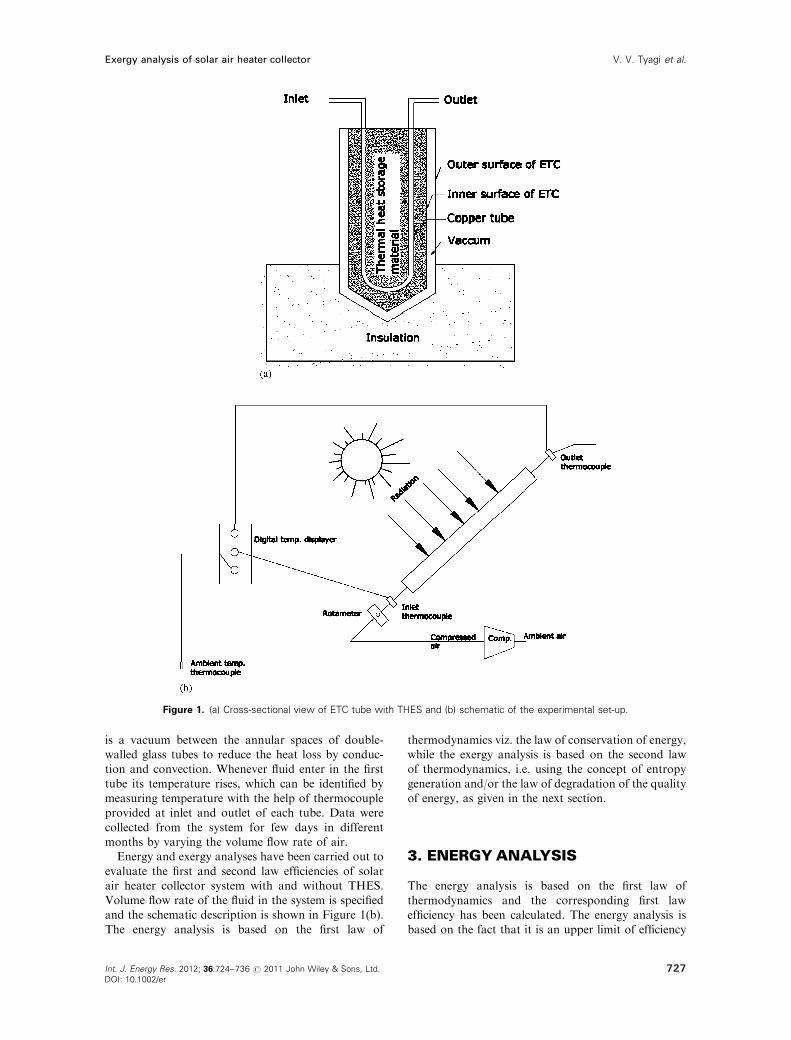
is a vacuum between the annular spaces of double-walled glass tubes to reduce the heat loss by conduc-tion and convection. Whenever fluid enter in the first
tube its temperature rises, which can be identified bymeasuring temperature with the help of thermocoupleprovided at inlet and outlet of each tube. Data were
collected from the system for few days in differentmonths by varying the volume flow rate of air.Energy and exergy analyses have been carried out to
evaluate the first and second law efficiencies of solarair heater collector system with and without THES.Volume flow rate of the fluid in the system is specifiedand the schematic description is shown in Figure 1(b).
The energy analysis is based on the first law of
thermodynamics viz. the law of conservation of energy,while the exergy analysis is based on the second lawof thermodynamics, i.e. using the concept of entropy
generation and/or the law of degradation of the qualityof energy, as given in the next section.
3. ENERGY ANALYSIS
The energy analysis is based on the first law of
thermodynamics and the corresponding first lawefficiency has been calculated. The energy analysis isbased on the fact that it is an upper limit of efficiency
Figure 1. (a) Cross-sectional view of ETC tube with THES and (b) schematic of the experimental set-up.
727
Exergy analysis of solar air heater collector V. V. Tyagi et al.
Int. J. Energy Res. 2012; 36:724–736 2011 John Wiley & Sons, Ltd.
DOI: 10.1002/er
r

with which the solar radiation can be converted intoheat and the heat can be transferred for usefulapplications at a given frequency spectrum and
intensity. Energy incident on the evacuated tube isgiven by
Qc ¼ AIs ð1Þ
where Qc is the energy incident on the collector tube,A is the projected area of collector tube exposed to thesun light, and Is is the intensity of solar radiation atany particular site. Useful energy gained from the
collector can be written as
Qu ¼ at IsA ð2Þ
where a is the absorptance of inner surface of ETC, t isthe transmittance of outer surface of the collector.Useful energy transmitted into the evacuated tubes isabsorbed by fluid, and can be calculated using the first
law of thermodynamics, viz. the law of conservation ofenergy:
Qu ¼ Qf ¼ _mCp DT ð3Þ
where Qf is the energy absorbed by air, Cp the specificheat of air and DT is the temperature difference and _m
is the mass flow rate of air, the first law efficiency of thecollector system is given by
Z ¼ Qf=Qc ¼ _mCpDT=AIs ð4Þ
where Z is the abbreviation used for first law efficiencyof the system.
4. EXERGY ANALYSIS
The rate at which exergy is collected by the solarcollector can be increased by increasing the mass flowrate of the working fluid. Since the collector tubes arethe most expensive component of any solar thermal
system which needs advanced material and associatedtechnology to build, therefore, it requires large invest-ment. In order to reduce the capital cost, we need to
optimize the dryer area, as the fuel (sunlight) is free.Again, for large mass flow rates, the fluid outlettemperature is very low and requires more power to
pump/blow air/fluid through it. On the other hand, lowflow rate results in high outlet temperature of theworking fluid with high specific work potential. But dueto the nature of entropy generation, exergy losses
increase due to the temperature differences and hence,the optimum mass flow rate is required. The exergyanalysis has been performed based on the configuration
of solar air heater collector shown in Figure 1(b). Theexergy received by collector is given by [8–11,23,24,28]
Exc ¼ Qcð1� Ta=TSÞ ð5Þ
where Ta is the ambient temperature, and TS is thetemperature of the source while, the exergy received byfluid is written as [8–11,23,24,28]:
Exf ¼ _mðEo � EiÞ ¼ _m ½ðho � hiÞ � Taðso � siÞ� ð6Þ
where ho is the output specific enthalpy, hi is the inputspecific enthalpy, so is the output entropy, si is the input
entropy, and _m is the mass flow rate of air blowingthrough the collector tubes. The output specific enthalpyof the fluid is given by [23,24,28]
ho ¼ CPo TO ð7Þ
where TO is outlet temperature, and CPo is the specificheat of air at outlet. The specific enthalpy of inlet air is
given by [23,24,28]
hi ¼ CPi Ti ð8Þ
where CPi is the input specific heat, Ti is the inlet
temperature. While the entropy difference has beencalculated using the following set of equations [23,24,28]:
CPi ¼ a1k� Ti ð9Þ
CPo ¼ a1k� TO ð10Þ
ds ¼ dq=T ¼ CP dT=T ¼ ða1bTÞ ðdT=TÞ¼ adT=T1kdT ð11Þ
Using Equations (9–10), the values of constantsa and k can be calculated and hence, the entropy
Table I. Details about the solar air heater collector and storage
materials.
Specification of collector tubes Values
Total length 179.5 cm
Inner length 176 cm
Coating length 172 cm
Inner diameter 44 mm
Outer diameter 57.5 mm
Properties of the Paraffin wax
as a PCM
Melting point 53.041C�
Specific heat 2.05 kJ kg1C�1
Latent heat of fusion 183.1 kJ kg�1�
Thermal conductivity 0.21 (solid) (W m K�1)
Density at 701C 0.769 kg m�3
Properties of HP Hytherm 500 Oil
Kinematic viscosity @ 40 c, cst 27–35
Flash point coc, c, min 194
Viscosity index 95
Power point c max 0.0
Copper strip corrosion 3 h @ 100 c
(astm), max
1.0
Neutralization number mg koh gm�1,
max
0.15
260c 0.731
280c 0.751
300c 0.772
260c 0.097
280c 0.096
300c 0.095
�Measured by Differential Scanning Calorimeter (DSC).
728 Int. J. Energy Res. 2012; 36:724–736 2011 John Wiley & Sons, Ltd.
DOI: 10.1002/er
r
Exergy analysis of solar air heater collectorV. V. Tyagi et al.
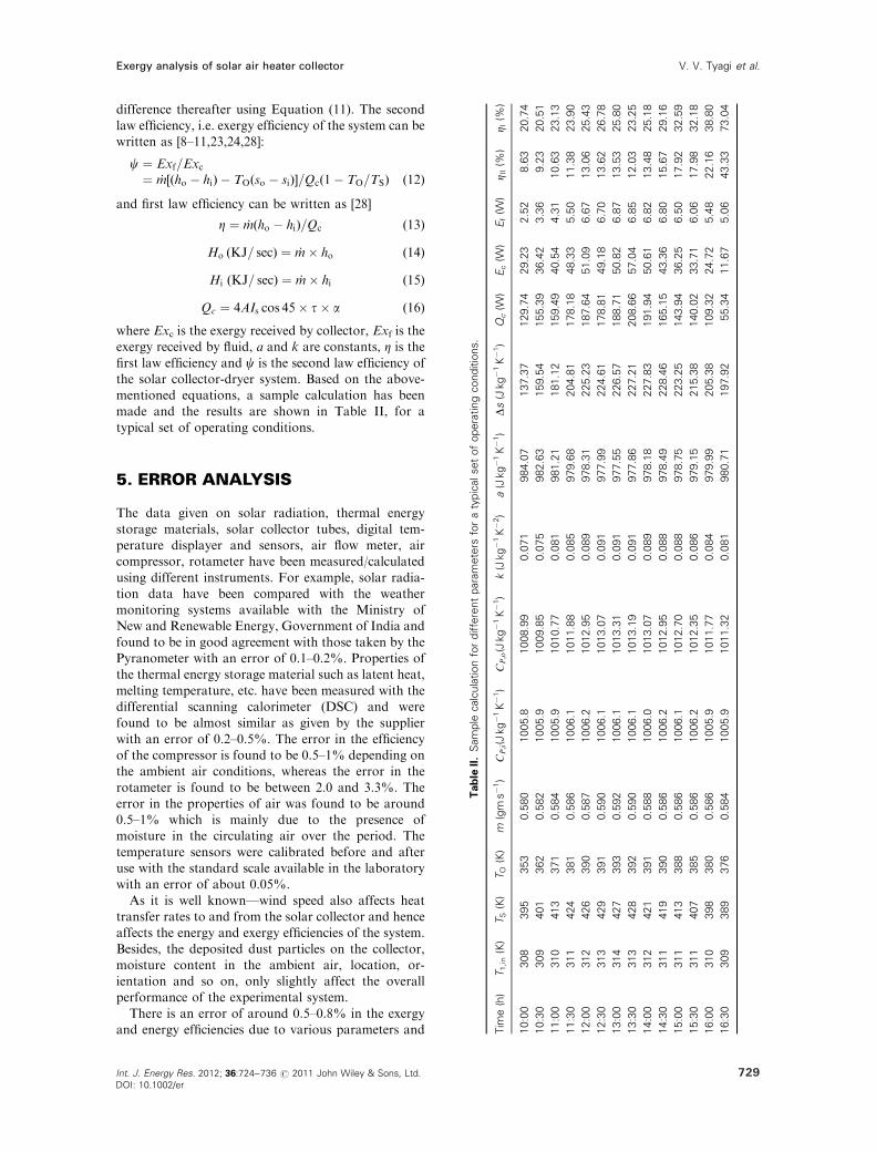
difference thereafter using Equation (11). The secondlaw efficiency, i.e. exergy efficiency of the system can bewritten as [8–11,23,24,28]:
c ¼ Exf=Exc¼ _m½ðho � hiÞ � TOðso � siÞ�=Qcð1� TO=TSÞ ð12Þ
and first law efficiency can be written as [28]
Z ¼ _mðho � hiÞ=Qc ð13Þ
Ho ðKJ= secÞ ¼ _m� ho ð14Þ
Hi ðKJ= secÞ ¼ _m� hi ð15Þ
Qc ¼ 4AIs cos 45� t� a ð16Þ
where Exc is the exergy received by collector, Exf is theexergy received by fluid, a and k are constants, Z is the
first law efficiency and c is the second law efficiency ofthe solar collector-dryer system. Based on the above-mentioned equations, a sample calculation has beenmade and the results are shown in Table II, for a
typical set of operating conditions.
5. ERROR ANALYSIS
The data given on solar radiation, thermal energy
storage materials, solar collector tubes, digital tem-perature displayer and sensors, air flow meter, aircompressor, rotameter have been measured/calculated
using different instruments. For example, solar radia-tion data have been compared with the weathermonitoring systems available with the Ministry ofNew and Renewable Energy, Government of India and
found to be in good agreement with those taken by thePyranometer with an error of 0.1–0.2%. Properties ofthe thermal energy storage material such as latent heat,
melting temperature, etc. have been measured with thedifferential scanning calorimeter (DSC) and werefound to be almost similar as given by the supplier
with an error of 0.2–0.5%. The error in the efficiencyof the compressor is found to be 0.5–1% depending onthe ambient air conditions, whereas the error in the
rotameter is found to be between 2.0 and 3.3%. Theerror in the properties of air was found to be around0.5–1% which is mainly due to the presence ofmoisture in the circulating air over the period. The
temperature sensors were calibrated before and afteruse with the standard scale available in the laboratorywith an error of about 0.05%.
As it is well known—wind speed also affects heattransfer rates to and from the solar collector and henceaffects the energy and exergy efficiencies of the system.
Besides, the deposited dust particles on the collector,moisture content in the ambient air, location, or-ientation and so on, only slightly affect the overallperformance of the experimental system.
There is an error of around 0.5–0.8% in the exergyand energy efficiencies due to various parameters and
Tab
leII
.S
am
ple
calc
ula
tion
for
diffe
rent
para
mete
rsfo
ra
typic
alset
of
opera
ting
conditio
ns.
Tim
e(h
)T
1,in
(K)
TS
(K)
TO
(K)
m(g
ms�
1)
CP;i(J
kg�
1K�
1)
CP;o
(Jkg�
1K�
1)
k(J
kg�
1K�
2)
a(J
kg�
1K�
1)
Ds
(Jkg�
1K�
1)
Qc
(W)
Ec
(W)
Ef
(W)
Z II(%
)Z I
(%)
10:0
0308
395
353
0.5
80
1005.8
1008.9
90.0
71
984.0
7137.3
7129.7
429.2
32.5
28.6
320.7
4
10:3
0309
401
362
0.5
82
1005.9
1009.8
50.0
75
982.6
3159.5
4155.3
936.4
23.3
69.2
320.5
1
11:0
0310
413
371
0.5
84
1005.9
1010.7
70.0
81
981.2
1181.1
2159.4
940.5
44.3
110.6
323.1
3
11:3
0311
424
381
0.5
86
1006.1
1011.8
80.0
85
979.6
8204.8
1178.1
848.3
35.5
011.3
823.9
0
12:0
0312
426
390
0.5
87
1006.2
1012.9
50.0
89
978.3
1225.2
3187.6
451.0
96.6
713.0
625.4
3
12:3
0313
429
391
0.5
90
1006.1
1013.0
70.0
91
977.9
9224.6
1178.8
149.1
86.7
013.6
226.7
8
13:0
0314
427
393
0.5
92
1006.1
1013.3
10.0
91
977.5
5226.5
7188.7
150.8
26.8
713.5
325.8
0
13:3
0313
428
392
0.5
90
1006.1
1013.1
90.0
91
977.8
6227.2
1208.6
657.0
46.8
512.0
323.2
5
14:0
0312
421
391
0.5
88
1006.0
1013.0
70.0
89
978.1
8227.8
3191.9
450.6
16.8
213.4
825.1
8
14:3
0311
419
390
0.5
86
1006.2
1012.9
50.0
88
978.4
9228.4
6165.1
543.3
66.8
015.6
729.1
6
15:0
0311
413
388
0.5
86
1006.1
1012.7
00.0
88
978.7
5223.2
5143.9
436.2
56.5
017.9
232.5
9
15:3
0311
407
385
0.5
86
1006.2
1012.3
50.0
86
979.1
5215.3
8140.0
233.7
16.0
617.9
832.1
8
16:0
0310
398
380
0.5
86
1005.9
1011.7
70.0
84
979.9
9205.3
8109.3
224.7
25.4
822.1
638.8
0
16:3
0309
389
376
0.5
84
1005.9
1011.3
20.0
81
980.7
1197.9
255.3
411.6
75.0
643.3
373.0
4
729
Exergy analysis of solar air heater collector V. V. Tyagi et al.
Int. J. Energy Res. 2012; 36:724–736 2011 John Wiley & Sons, Ltd.
DOI: 10.1002/er
r
the performance accuracy of the instruments. But asmentioned above, wind speed and deposition of dustparticle were not taken into account in the present
experimental study. Therefore, the overall influences ofthese input errors on the total results can also be verysmall and hence, can be neglected in the present study.
However, to make an error-free system, all the para-meters mentioned above must be taken into accountfor the better accuracy and performance of such sys-tems for real-life applications.
6. RESULTS AND DISCUSSION
A comparative study on first and second law analysesof a typical solar air heater collector system with and
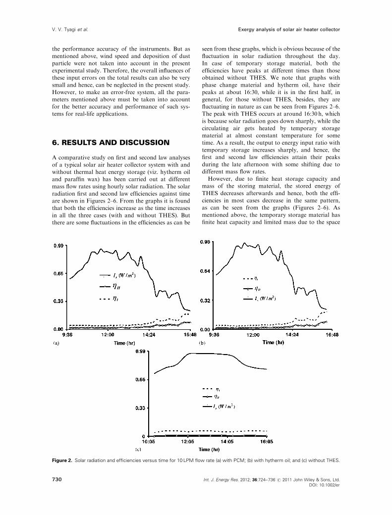
without thermal heat energy storage (viz. hytherm oiland paraffin wax) has been carried out at differentmass flow rates using hourly solar radiation. The solar
radiation first and second law efficiencies against timeare shown in Figures 2–6. From the graphs it is foundthat both the efficiencies increase as the time increases
in all the three cases (with and without THES). Butthere are some fluctuations in the efficiencies as can be
seen from these graphs, which is obvious because of thefluctuation in solar radiation throughout the day.In case of temporary storage material, both the
efficiencies have peaks at different times than thoseobtained without THES. We note that graphs withphase change material and hytherm oil, have their
peaks at about 16:30, while it is in the first half, ingeneral, for those without THES, besides, they arefluctuating in nature as can be seen from Figures 2–6.The peak with THES occurs at around 16:30 h, which
is because solar radiation goes down sharply, while thecirculating air gets heated by temporary storagematerial at almost constant temperature for some
time. As a result, the output to energy input ratio withtemporary storage increases sharply, and hence, thefirst and second law efficiencies attain their peaks
during the late afternoon with some shifting due todifferent mass flow rates.However, due to finite heat storage capacity and
mass of the storing material, the stored energy of
THES decreases afterwards and hence, both the effi-ciencies in most cases decrease in the same pattern,as can be seen from the graphs (Figures 2–6). As
mentioned above, the temporary storage material hasfinite heat capacity and limited mass due to the space
Figure 2. Solar radiation and efficiencies versus time for 10 LPM flow rate (a) with PCM; (b) with hytherm oil; and (c) without THES.
730 Int. J. Energy Res. 2012; 36:724–736 2011 John Wiley & Sons, Ltd.
DOI: 10.1002/er
r
Exergy analysis of solar air heater collectorV. V. Tyagi et al.
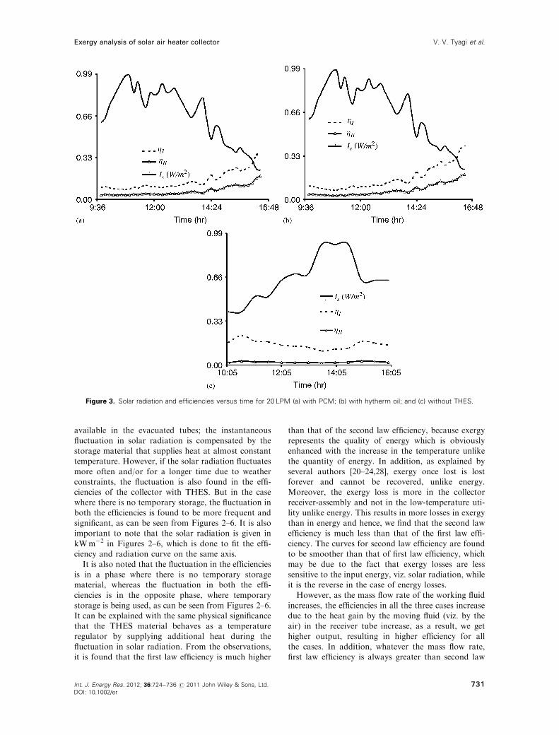
available in the evacuated tubes; the instantaneous
fluctuation in solar radiation is compensated by thestorage material that supplies heat at almost constanttemperature. However, if the solar radiation fluctuates
more often and/or for a longer time due to weatherconstraints, the fluctuation is also found in the effi-ciencies of the collector with THES. But in the casewhere there is no temporary storage, the fluctuation in
both the efficiencies is found to be more frequent andsignificant, as can be seen from Figures 2–6. It is alsoimportant to note that the solar radiation is given in
kWm�2 in Figures 2–6, which is done to fit the effi-ciency and radiation curve on the same axis.It is also noted that the fluctuation in the efficiencies
is in a phase where there is no temporary storagematerial, whereas the fluctuation in both the effi-ciencies is in the opposite phase, where temporary
storage is being used, as can be seen from Figures 2–6.It can be explained with the same physical significancethat the THES material behaves as a temperatureregulator by supplying additional heat during the
fluctuation in solar radiation. From the observations,it is found that the first law efficiency is much higher
than that of the second law efficiency, because exergy
represents the quality of energy which is obviouslyenhanced with the increase in the temperature unlikethe quantity of energy. In addition, as explained by
several authors [20–24,28], exergy once lost is lostforever and cannot be recovered, unlike energy.Moreover, the exergy loss is more in the collectorreceiver-assembly and not in the low-temperature uti-
lity unlike energy. This results in more losses in exergythan in energy and hence, we find that the second lawefficiency is much less than that of the first law effi-
ciency. The curves for second law efficiency are foundto be smoother than that of first law efficiency, whichmay be due to the fact that exergy losses are less
sensitive to the input energy, viz. solar radiation, whileit is the reverse in the case of energy losses.However, as the mass flow rate of the working fluid
increases, the efficiencies in all the three cases increasedue to the heat gain by the moving fluid (viz. by theair) in the receiver tube increase, as a result, we gethigher output, resulting in higher efficiency for all
the cases. In addition, whatever the mass flow rate,first law efficiency is always greater than second law
Figure 3. Solar radiation and efficiencies versus time for 20 LPM (a) with PCM; (b) with hytherm oil; and (c) without THES.
731
Exergy analysis of solar air heater collector V. V. Tyagi et al.
Int. J. Energy Res. 2012; 36:724–736 2011 John Wiley & Sons, Ltd.
DOI: 10.1002/er
r
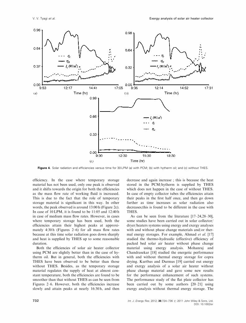
efficiency. In the case where temporary storagematerial has not been used, only one peak is observedand it shifts towards the origin for both the efficiencies
as the mass flow rate of working fluid is increased.This is due to the fact that the role of temporarystorage material is significant in this way. In other
words, the peak observed is around 13:00 h (Figure 2c).In case of 10LPM, it is found to be 11:05 and 12:40 hin case of medium mass flow rates. However, in caseswhere temporary storage has been used, both the
efficiencies attain their highest peaks at approxi-mately 4:30 h (Figures 2–6) for all mass flow ratesbecause at this time solar radiation goes down sharply
and heat is supplied by THES up to some reasonableduration.Both the efficiencies of solar air heater collector
using PCM are slightly better than in the case of hy-therm oil. But in general, both the efficiencies withTHES have been observed to be better than those
without THES. Besides, as the temporary storagematerial regulates the supply of heat at almost con-stant temperature, both the efficiencies are found to besmoother than that without THES as can be seen from
Figures 2–6. However, both the efficiencies increaseslowly and attain peaks at nearly 16:30 h, and then
decrease and again increase ; this is because the heatstored in the PCM/hytherm is supplied by THESwhich does not happen in the case of without THES.
In case of empty collector tubes the efficiencies attaintheir peaks in the first half once, and then go downfurther as time increases as solar radiation also
decreases;this is found to be different in the case withTHES.As can be seen from the literature [17–24,28–30],
some studies have been carried out in solar collector/
dryer/heaters systems using energy and exergy analyseswith and without phase change materials and/or ther-mal energy storages. For example, Ahmad et al. [17]
studied the thermo-hydraulic (effective) efficiency ofpacked bed solar air heater without phase changematerial using energy analysis. Mohanraj and
Chandrasekar [18] studied the energetic performancewith and without thermal energy storage for copradrying. Kurtbas and Durmus [19] carried out energy
and exergy analysis of a solar air heater withoutphase change material and gave some new resultsfor the performance enhancement of such systems.The performance study of the flat plate collector has
been carried out by some authors [20–21] usingexergy analysis without thermal energy storage. The
Figure 4. Solar radiation and efficiencies versus time for 30 LPM (a) with PCM; (b) with hytherm oil; and (c) without THES.
732 Int. J. Energy Res. 2012; 36:724–736 2011 John Wiley & Sons, Ltd.
DOI: 10.1002/er
r
Exergy analysis of solar air heater collectorV. V. Tyagi et al.

performance analysis and parametric study of para-
bolic trough concentrating collector have been carriedout by different authors [22–24] using energy andexergy analyses without thermal energy storage and
some useful results were also obtained. For example,in Reference [23–24] the authors studied the effects ofconcentrating ratio and mass flow rate of the workingfluid on the first and second law analyses of con-
centrating collector and observed that the mass flowrate is a critical parameter and should be chosen verycarefully to obtain the best performance of these solar
collectors. Tyagi et al. [28] carried out the performanceof an evacuated tube solar collector without any phasechange material-based thermal energy storage. Similar
studies have been carried out by other authors on flatplate collectors and/or solar air heaters, such as Kocaet al. [29], and Akbulut and Durmus [30] using energy
and exergy analyses and some useful results weregiven. But none of the studies mentioned above isconcentrated on the evacuated tube solar air heatercollector using different thermal energy storage mate-
rials and hence, the work presented in this paper is newand unique of this kind.
7. CONCLUSIONS
The comparative study based on the first and secondlaw analyses of a typical solar air heater collectorsystem with and without temporary thermal energystorage has been carried out at different mass flow
rates using hourly solar radiation. From the presentexperimental study, some interesting results are foundand can be summarized as follows:
� It is found that there is fluctuation in both the
efficiencies which is mainly due to the fact thatsolar radiation also fluctuates throughout the dayas can be seen clearly from the figures given in this
paper. In addition, as time increases, both theefficiencies first increase and then decrease in casewithout temporary storage material and thesimilar trend is found for solar radiation.
� In case of without THES material, the efficiencyincreases with time, attains its peak in the first
half in general (Figures 2–6) and then decreasesafter that. However, in cases where temporaryheat storage material is used, both the efficiencies
Figure 5. Solar radiation and efficiencies versus time for 40 LPM (a) with PCM; (b) with hytherm oil; and (c) without THES.
733
Exergy analysis of solar air heater collector V. V. Tyagi et al.
Int. J. Energy Res. 2012; 36:724–736 2011 John Wiley & Sons, Ltd.
DOI: 10.1002/er
r
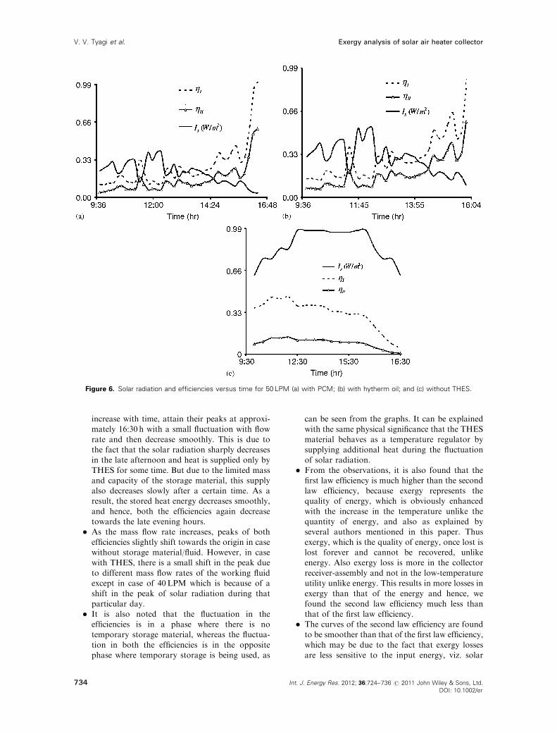
increase with time, attain their peaks at approxi-mately 16:30 h with a small fluctuation with flow
rate and then decrease smoothly. This is due tothe fact that the solar radiation sharply decreasesin the late afternoon and heat is supplied only by
THES for some time. But due to the limited massand capacity of the storage material, this supplyalso decreases slowly after a certain time. As aresult, the stored heat energy decreases smoothly,
and hence, both the efficiencies again decreasetowards the late evening hours.
� As the mass flow rate increases, peaks of both
efficiencies slightly shift towards the origin in casewithout storage material/fluid. However, in casewith THES, there is a small shift in the peak due
to different mass flow rates of the working fluidexcept in case of 40LPM which is because of ashift in the peak of solar radiation during that
particular day.� It is also noted that the fluctuation in the
efficiencies is in a phase where there is notemporary storage material, whereas the fluctua-
tion in both the efficiencies is in the oppositephase where temporary storage is being used, as
can be seen from the graphs. It can be explainedwith the same physical significance that the THES
material behaves as a temperature regulator bysupplying additional heat during the fluctuationof solar radiation.
� From the observations, it is also found that thefirst law efficiency is much higher than the secondlaw efficiency, because exergy represents thequality of energy, which is obviously enhanced
with the increase in the temperature unlike thequantity of energy, and also as explained byseveral authors mentioned in this paper. Thus
exergy, which is the quality of energy, once lost islost forever and cannot be recovered, unlikeenergy. Also exergy loss is more in the collector
receiver-assembly and not in the low-temperatureutility unlike energy. This results in more losses inexergy than that of the energy and hence, we
found the second law efficiency much less thanthat of the first law efficiency.
� The curves of the second law efficiency are foundto be smoother than that of the first law efficiency,
which may be due to the fact that exergy lossesare less sensitive to the input energy, viz. solar
Figure 6. Solar radiation and efficiencies versus time for 50 LPM (a) with PCM; (b) with hytherm oil; and (c) without THES.
734 Int. J. Energy Res. 2012; 36:724–736 2011 John Wiley & Sons, Ltd.
DOI: 10.1002/er
r
Exergy analysis of solar air heater collectorV. V. Tyagi et al.
radiation, while it is the reverse in the case ofenergy losses.
Thus, the results obtained in this study will be veryuseful and informative for real-life applications using
temporary storage in both the solar collector and in thethermal energy utilities for better performance. Mostimportantly, there is a need for thermal energy without
much fluctuation in the outlet temperature and heatcontent out of the solar collector system for variousapplications of physical importance.
NOMENCLATURE
A 5 projected area of collector tube ex-
posed to the sun light (m2)CPo 5 specific heat of air at the outlet
(J kg�1K�1)CPi 5 input specific heat (J kg�1K�1)
CP 5 specific heat of air (J kg�1K�1)Exf 5 exergy received by fluid (W)Exc 5 exergy received by collector (W)
ho 5 output specific enthalpy (kJ kg�1)hi 5 input specific enthalpy (kJ kg�1)Ho 5 output enthalpy (kJ)
Hi 5 input enthalpy (kJ)Is 5 intensity of solar radiation at any
particular site (Wm�2)_m 5mass flow rate of air (gm s�1)Qc 5 energy incident on the dryer/ evacu-
ated tube (W)Qf 5 energy absorbed by air (W)
si 5 input entropy (J kg�1K�1)so 5 output entropy (J kg�1K�1)DT 5 temperature difference (K)
Ta 5 ambient temperature (K)Ti 5 inlet temperature (K)TO 5 outlet temperature (K)
TS 5 temperature of source (K)
Greek letters
a 5 absorptance of inner surface of ETCt 5 transmittance of the collector tubeZ 5 first law efficiency of the collector
systemc 5 second law (exergy) efficiency of the
system
ACKNOWLEDGEMENTS
The productive and encouraging comments andsuggestions given by the reviewers are gratefullyacknowledged. The required modification in graphicsdone by Mr Vishal Bhatti, Senior Technical Assistant,School of Architecture & Landscape Design, SMVD
University, Katra is duly acknowledged. This workwas financially supported by the Ministry of New &Renewable Energy, Government of India.
REFERENCES
1. Tyagi SK, Kim MS, Park SR, Anand S. Second law
based performance of a modified VAC hybrid heat
pump system using NH3-H2O as the working fluid.
Indian Journal of Pure and Applied Physics 2010;
48:212–219.
2. Tyagi SK, Park SR, Tyagi VV, Anand S. Second
law based performance evaluation and parametric
study of a sea water source cascade heat pump.
International Journal of Exergy 2010; 7(3):369–386.
3. Tyagi SK, Wang SW, Sharma A, Kaushik SC.
Application of solar collectors to control the plume
from wet cooling towers in a commercial building:
a case study. Applied Thermal Engineering 2007;
27:1394–1404.
4. Kovarik M, Lesse PF. Optimal control of flow in
low temperature solar heat collectors. Solar Energy
1976; 18:431–435.
5. Farries DR, Melsa JL, Murray HS. Energy conser-
vation by adaptive control for a solar heated building.
Proceedings of IEEE International Conference on
Cybernetics and Society, Washington, DC, U.S.A.,
1977.
6. Orbach A, Fischl R, Herczfeld PR, Konyk Jr S.
Optimal and suboptimal control strategies and
sensitivity study for solar liquid collector systems.
Proceedings of ISES, Atlanta, U.S.A., 1979.
7. Winn RC, Winn CB. Optimal control of mass flow
rate in flat plate solar collectors. ASME Journal of
Solar Energy Engineering 1981; 103:113–120.
8. Bejan A, Kearney DW, Kreith F. Second law
analysis and synthesis of solar collector systems.
ASME Journal of Solar Energy Engineering 1981;
103:23–28.
9. Bejan A. Extraction of exergy from solar collectors
under time-varying conditions. International Journal
of Heat and Fluid Flow 1982; 3:67–72.
10. Singh N, Kaushik SC. Technology Assessment and
Economic Evaluation of Solar Thermal Power Systems—
A State of Art Report, Centre for Energy Studies,
Indian Institute of Technology, Delhi, India, 1993.
11. Misra RD. Second law assessment of solar thermal
power generation. M.Tech. Thesis, Centre for Energy
Studies; Indian Institute of Technology, Delhi,
India, 1996.
12. Fath HES. Thermal performance of a simple design
solar air heater build in thermal energy storage
system. Renewable Energy 1995; 6:1033–1039.
735
Exergy analysis of solar air heater collector V. V. Tyagi et al.
Int. J. Energy Res. 2012; 36:724–736 2011 John Wiley & Sons, Ltd.
DOI: 10.1002/er
r
13. Pangavhane DR, Sawhney RL. Review of research
and development work on solar driers for grape
drying. Energy Conversion and Management 2002;
43:45–61.
14. Midilli A. Determination of pistachio drying behavior
and conditions in a solar drying system. International
Journal of Energy Research 2001; 25:715–725.
15. Shanmugam V, Natarajan E. Experimental study
of regenerative desiccant integrated solar dryer with
and without reflective mirror. Applied Thermal
Engineering 2007; 27:1543–1551.
16. Hawlader MNA, Uddin MS, Khin MM. Micro-
encapsulated PCM thermal energy storage system.
Applied Energy 2003; 74:195–202.
17. Ahmad A, Saini JS, Varma HK. Thermo-hydraulic
performance of packed bed solar air heaters. Energy
Conversion and Management 1996; 37:205–214.
18. Mohanraj M, Chandrasekar P. Performance of
a solar drier with and without heat storage material
for copra drying. International Journal of Global
Energy Issues 2009; 32:112–121.
19. Kurtbas I, Durmus A. Efficiency and exergy
analysis of a new solar air heater. Renewable Energy
2004; 29:1489–1501.
20. Luminosu I, Fara L. Determination of the optimal
operation mode of a flat solar collector by exergetic
analysis and numerical simulation. Energy 2005;
30:731–747.
21. Torres-Reyes JJ, Gonzalez N, Zaleta-Aguilar A,
Gortari JGC. Optimal process of solar to thermal
energy conversion and design of irreversible flat
plate solar collectors. Energy 2003; 28:99–113.
22. Bakos C, Ioannidis I, Tsagas NF, Seftelis I. Design
optimization and conversion efficiency determination
of a line-focus-parabolic-trough solar collector.
Applied Energy 2001; 68:43–50.
23. Kaushik SC, Singhal MK, Tyagi SK. Solar
Collector Technologies for Power Generation and
Space Air Conditioning Applications—A State of the
Art Internal Report, Centre for Energy Studies;
Indian Institute of Technology, Delhi, India, 2001.
24. Tyagi SK, Wang SW, Kaushik SC, Singhal MK,
Park SR. Exergy analysis and parametric study
of concentrating type solar collectors. International
Journal of Thermal Sciences 2007; 46:1304–1310.
25. Ozturk HH, Demirel Y. Exergy-based performance
analysis of packed-bed solar air heaters. Inter-
national Journal of Energy Research 2004; 28:
423–432.
26. Potdukhe PA, Thombre SB. Development of a new
type of solar dryer: its mathematical modeling
and experimental evaluation. International Journal
of Energy Research 2008; 32:765–782.
27. MacPhee D, Dincer I. Thermal modeling of a
packed bed thermal energy storage system during
charging. Applied Thermal Engineering 2009; 29:
695–705.
28. Tyagi SK, Tyagi VV, Anand S, Chandra V,
Diwedi RC. First and second law analyses of a
typical solar dryer—a case study. International
Journal of Sustainable Energy 2010; 29:8–18.
29. Koca A, Oztop HF, Koyun T, Varol Y. Energy
and exergy analysis of a latent heat storage system
with phase change material for a solar collector.
Renewable Energy 2008; 33:567–574.
30. Akbulut A, Durmus A. Energy and exergy analyses
of thin layer drying of mulberry in a forced solar
dryer. Energy 2010; 35:1754–1763.
736 Int. J. Energy Res. 2012; 36:724–736 2011 John Wiley & Sons, Ltd.
DOI: 10.1002/er
r
Exergy analysis of solar air heater collectorV. V. Tyagi et al.