comparative analysis of microwave link using space and
TRANSCRIPT

Buletin Pos dan Telekomunikasi Vol. 19 Issue 1 (2021): 41-58
41
Comparative Analysis of Microwave Link Using Space and Hybrid Diversity Configuration on Mountain Topography Area Ade Wahyudin1, Alfin Hikmaturokhman2 1Sekolah Tinggi Multi Media Yogyakarta 2Institut Teknologi Telkom Purwokerto 1Jalan Magelang Km. 6 Yogyakarta 55284, Indonesia 2Jl. D. I. Panjaitan No. 128 Purwokerto 53147, Jawa Tengah, Indonesia Email: [email protected], [email protected]
A R T I C L E I N F O R M A T I O N A B S T R A C T
Received on 27 December 2020 Revised on 8 August 2021 Accepted on 13 August 2021
Keywords: Space Diversity Hybrid Diversity Availability Microwave Mountain
The penetration of telecommunication infrastructure in Indonesia is growing significantly every year. However, this growth is not comparable to the technology distribution in remote areas, especially areas with mountainous contours. So it takes a proper backhaul network design to deploy telecommunication services in remote areas. Microwave transmission technology is widely used as a backhaul network in mountainous areas. However, multipath fading becomes a problem in microwave communication, so we use the diversity configuration approach to solve it. Space diversity configurations are the system most often used, but in more extreme conditions it can use a hybrid diversity configuration, a combination of space and frequency diversity. In this study, we design and compare the performance of two types of diversity configurations, namely space and hybrid diversity in cross-mountainous areas using simulation software Pathloss 5.0. Before comparison, these paths are tested with a point-to-point configuration to assess the communication performance using a microwave link. Based on the simulation, the resulting cross-mountain microwave communication performance using point-to-point configuration results in 99.98179% availability and 5742.79 seconds unavailability in one year. These values are still far from the ITU-T G.821 standard, namely 99.99% availability. In the configuration using Space Diversity, the quality has increased. Still, it cannot meet ITU standards because it can only produce 99.98333% to 99.98943% availability or comparable to un-availability for 5255.53 to 3332.48 seconds/year. Meanwhile, the hybrid diversity configuration can produce a performance that meets ITU standards with availability of 99.99122% or equivalent to un-availability for 2769.79 seconds per year.
1. Introduction
The growth of telecommunication and ICT infrastructure and services in Indonesia increasing rapidly, resulting in the need for adequate infrastructure both in quality and capacity. This is due to the growth of ICT service users in Indonesia, which is increasing significantly up to 10.12% per year (Badan Pusat Statistik, 2018). Therefore, the development of telecommunications infrastructure is the key to the increasing penetration and equitable deployment of ICT infrastructure and services in all regions of Indonesia.
In terms of deploying ICT infrastructure, geographically, Indonesia has an archipelago as well as a row of hills and mountains, so it requires good planning. Palapa Ring is expected to support the access network, backhaul to the backbone of ICT services throughout Indonesia (Kementerian Komunikasi dan Informatika, 2013). However, not all areas in Indonesia can be supported by fiber optics. Mountainous and remote areas still use other suitable communication media such as satellites and microwaves. Microwave communication has an important role in ICT infrastructure deployment, especially remote and extreme topology areas that are impossible to reach by fiber optic (Hikmaturokhman & Wahyudin, 2018). So that to overcome the obstacles caused by geographical conditions, a proper microwave link design is needed.
DOI: 10.17933/bpostel.2021.190104

Buletin Pos dan Telekomunikasi Vol. 19 Issue 1 (2021): 41-58
42
This technology uses electromagnetic waves that have micro wavelengths or are called microwaves and antennas as a means to transmit signals so they can be used to communicate (Hikmaturokhman et al., 2017). Microwave radio communication systems play an important role in cellular communication systems, especially in point-to-point backhaul communication between Base Stations or Base Stations Towards a Radio Access Network (RAN). The basic configuration of a microwave communication system is point-to-point, which consists of a transmitter and a receiver as a medium for sending and receiving signals (Kizer, 2013). The process of propagating from the transmitting antenna to the receiving antenna, radio waves through various paths with some propagation paths. The basic mechanism of microwave communication is the Line of Sight (LOS), a condition where the transmitter and the receiver can be directly connected without any obstacles, as illustrated in Figure 1.
Figure 1. Line of sight communication (Hikmaturrokhman & Wahyudin, 2018)
In this research, the microwave link deployed across a mountain range on South Sulawesi Province, connecting a network between the Kaleakan site in North Toraja District to the Walenrang site in Luwu District. Because this communication path is in a mountainous area with an average altitude range from 2000 to 3000 meters above sea level, the possibility of disturbance is very high. The most likely disturbance is transmitted signal allows for transmission loss due to multipath fading. Multipath fading is a disturbance caused by multiple signal trajectories caused by reflection, refraction, diffraction, and scattering in signal propagation (Dewanti et al., 2017).
The method to anticipate multipath fading is space diversity, which is one of several wireless diversity schemes that use two or more antennas to increase the quality and reliability of the system (Freeman, 2007). The conventional space diversity configuration uses one additional antenna that acts as a receiver, which is used to amplify the signal received from multipath. In addition to the Space Diversity configuration, there is a Hybrid Diversity configuration that combines Space Diversity and Frequency Diversity. So, it can amplify the signal and has a longer range, but Hybrid Diversity has very expensive costs to deploy (Wahyudin & Hikmaturokhman, 2021).
The main indicator of microwave implementation is system reliability, represented in the value of availability or unavailability (Oktaviasari et al., 2018). This indicator can determine the condition of system performance and can see the system’s reliability. The greater the availability value obtained, the better the quality given. So, if observed from a geographic point of view, it is also very necessary to select and use a good antenna and system design (Lehpamer, 2010).
So based on the background, the author is interested in studying the research with the title “Comparative Analysis of Microwave Link Using Space and Hybrid Diversity Configuration on Mountain Topography Area”, where the authors designed a microwave radio transmission network in remote areas in the mountains, Toraja, South Sulawesi. The point-to-point antenna configuration is designed in advance to show the performance of microwave radio transmission networks without diversity. The diversity configuration is

Comparative Analysis of Microwave Link Using Space and Hybrid Diversity Configuration on Mountain Topography Area (Ade Wahyudin, dkk)
43
designed to compare the performance of two antenna diversity configurations, namely Space diversity and Hybrid Diversity, then compare and analyze the design simulation results and parameters such as Availability, Unavailability, Free Space Loss, EIRP, RSL, and Fading Margin.
2. Literature Review
2.1. Previous Works
Based on previous research about the use of space diversity in a suburban area, conclude the availability of microwave links can increase up to a value of 99.9999%. Also, the highest diversity receives signal was obtained at 200λ, with the value of diversity receive signal is -83.94 dBm. Thus, the further distance between the antennas, the higher diversity of receive signal (Pradana & Wahyudin, 2018). In another study about the use of frequency diversity in the ocean’s topology concluded that the value of reliability or system availability that uses frequency diversity is 99.96879%, with an outage time of 8603.03 seconds/year (Rahmawati & Wahyudin, 2018). While the research on the use of space and hybrid diversity in the ocean shows that both of the configurations resulting in an excellent quality of communication in terms of availability and fading margin (Wahyudin & Hikmaturokhman, 2021).
2.2. Atmospheric Effect in Microwave Communication System
The atmospheric effect such as temperature, humidity, and rain are the effects that occur in the earth's atmosphere. Raindrops cause attenuation to electromagnetic waves. The heavier the rain, the greater the attenuation. The consequence of the atmospheric effect in microwave communication is the occurrence of absorption, refraction, and ducting (Hikmaturokhman et al., 2017). Absorption is caused by oxygen in the atmosphere, rain, and fog. It causes the energy propagated to experience attenuation. The oxygen in the atmosphere absorbs some of the energy from the microwaves, but this attenuation has little effect. While refraction is the deflection of radio waves due to changes in atmospheric characteristics (changes in temperature, atmospheric density, humidity). Changes in atmospheric density also affect the speed of propagation of the waves. Then, ducting is the phenomenon of trapping microwaves in an atmospheric waveguide. The ducting phenomenon usually occurs at low altitudes with a very dense layer of the atmosphere and occurs near or above the water surface (Winch, 1998).
2.3. Terrain Effect in Microwave Communication System
Terrain effect is an effect caused by a barrier or object that obstructs the Line of Sight, such as are reflection and diffraction. Reflection causes the beam to change its phase angle, a microwave beam that changes the phase angle can cause an amplification or attenuation of the beam energy. One example of reflection is, for example, ground reflection (Freeman, 2007). Diffraction is a characteristic of electromagnetic waves that occurs when a beam hits a barrier. Diffraction occurs when radio waves hit objects or obstructions in the form of sharp edges, corners, or a surface edge. The diffraction of radio waves will break down and reach the shadowed region. Waves with high frequency tend to follow LOS and do not experience diffraction to the area behind the shadowed region. While, for lower frequencies, diffraction occurs more frequently and results in more shadowed region loss (Hikmaturokhman & Wahyudin, 2018).
2.4. Fresnel Zone
Fresnel zone or fresnel area is an ellipsoidal region formed from radiation emitting from the transmitter antenna and receiver antenna. The Fresnel zone size is determined by the frequency of operation and the

Buletin Pos dan Telekomunikasi Vol. 19 Issue 1 (2021): 41-58
44
distance between the two sites. Fresnel zone is obtained by the following formula (Hikmaturokhman & Wahyudin, 2018),
𝐹𝑛 = 17,3)!#!#"$# …………………………………….……………………………………………… 2)
Where, Fn is n-th fresnel area radius (km); d1 and d2 are the distance between the transmitter and the barrier, and vice versa (km); d is the sum of d1 and d2; f is the frequency (GHz).
2.5. Diversity Antenna Method
a. Space Diversity
In this system, the receiver uses two antennas that are installed vertically at a certain distance. To get optimal performance, the spacing between two vertically separated antennas is the following formula (Kizer, 2013), 𝑠 = %×'×(
)…………………………………………………………………………………………..….. 3)
Where, s is spacing between antennas (m), λ is the wavelength (m), R is the radius of the earth (6370 km), and D is path length (km). If the transmission system uses space diversity techniques to overcome fading, an improvement factor will be obtained with the following equation,
𝐼*# =+.-×+.#$×/×*"×$×+.(&'#()/!+
) ………………………………………….………………………….. 4)
Where Isd is the improvement factor, η is the switching diversity coefficient (ideally is 1), s is spacing between antennas (m), FM is fading margin, v is the difference in gain of the two antennas. The equation can be converted into decibels with the following equation, 𝐼!" = 20 log 𝑠 + 10 log 𝑓 − 10 log𝐷 + 𝐹𝑀 − 𝑣 − 29.1 ……………………………………………………. 5) After that, the fading margin equation for space diversity configuration can be calculated with the following formula, 𝐹𝑀 = 20𝑙𝑜𝑔𝐷 + 5𝑙𝑜𝑔(𝑎𝑥𝑏𝑥2,5)– 5𝑙𝑜𝑔𝑈𝑛𝐴𝑣𝑝𝑎𝑡ℎ– 10𝑙𝑜𝑔𝑠 + #
$𝑣– 15,4 ………….…….………. 6)
b. Frequency Diversity
In the frequency diversity technique, the system uses an antenna with two different frequencies. The frequency difference (Δf) between the two frequencies is 2%-6% to avoid interference. If the transmission system uses the frequency diversity technique to overcome fading, then the improvement factor will be obtained with the following formula (Hikmaturokhman & Wahyudin, 2018), 𝐼$# =
..0×∆$$"×)
× 1023/+. ……………………………………………………………………………..…. 7)
Where Δf is the difference in frequency diversity. The equation can be converted into decibels with the following equation, 𝐼$# = 10𝑙𝑜𝑔∆𝑓 − 20 log 𝑓 − 10 log𝐷 + 𝐹𝑀0.9 ………………………………………………..….. 8) After that, the fading margin equation for frequency diversity configuration can be calculated with the following formula, 𝐹𝑀 = 20 log𝐷 + 5 log(𝑎 × 𝑏 × 2.5) + 15 log 𝑓 − 5 log𝑈𝑛𝐴𝑣5678 − 5 log ∆𝑓 − 29.5 ……...……. 9)

Comparative Analysis of Microwave Link Using Space and Hybrid Diversity Configuration on Mountain Topography Area (Ade Wahyudin, dkk)
45
c. Hybrid Diversity
Hybrid diversity combines space and frequency diversity configuration. The system improvement is determined by the mechanism of selecting the highest improvement factor between space and frequency diversity (Kizer, 2013).
𝐼229:) = 𝐼229;)𝑜𝑟𝐼2292), 𝑠𝑒𝑙𝑒𝑐𝑡𝑡ℎ𝑒ℎ𝑖𝑔ℎ𝑒𝑠𝑡𝑠𝑐𝑜𝑟𝑒 ………………….……………………..…. 10)
IFF-HD = Hybrid Diversity Flat Fading diversity improvement factor
𝐼)29:) = 𝐼)29;)𝑜𝑟𝐼)292), 𝑠𝑒𝑙𝑒𝑐𝑡𝑡ℎ𝑒ℎ𝑖𝑔ℎ𝑒𝑠𝑡𝑠𝑐𝑜𝑟𝑒 ……………………………………….….. 11)
IDF-HD = Hybrid Diversity Diverse Fading diversity improvement factor
2.6. Availability
Availability affects system reliability. The system reliability measure is often referred to as availability. Availability is often referred to as reliability which is defined by the system's ability to provide services. The opposite of availability is unavailability or outage time, which means the system fails to provide services (Lehpamer, 2010).
To get diversity availability, calculate the unavailability diversity with the following equation, 𝑈𝑛𝐴𝑣𝑝𝑎𝑡ℎ"%&'(!%)* =
+,-&./)01!"#$%&"'(
………………………………………………………..………...……..………. 12) Where diversity availability is a division between unavailability non-diversity and diversity improvement
factors so that availability space diversity can be calculated with the following equation, Avpath234567389 = (1–UnAvpath234567389)x100% ………………………………………………..…..…..….. 13)
2.7. Link Budget Calculation
a. Microwave Transmission Path The distance between sites can be calculated by determining the nominal position of two points on the earth line and calculating the distance. The nominal location of a point is usually expressed in terms of latitude and longitude. Each point of latitude and longitude is expressed in degrees, minutes, and seconds. The value needs to be converted first in units of degrees and converted into km. So, to change the nominal point from hours minutes to seconds to hour values only is to use the equations (Hikmaturokhman et al., 2017). 𝐿𝑎𝑡𝑖𝑡𝑢𝑑𝑒𝑎𝑛𝑑𝑙𝑜𝑛𝑔𝑖𝑡𝑢𝑑𝑒 = 𝑑𝑒𝑟𝑎𝑗𝑎𝑡 +<=!>7
?.+#=7>@
%?.. ……………………………………………… 14)
𝐿𝑎𝑡𝑖𝑡𝑢𝑑𝑒𝐷𝑖𝑠𝑡𝑎𝑛𝑐𝑒 = |𝐿𝑎𝑡𝑖𝑡𝑢𝑑𝑒𝑜𝑓𝑆𝑖𝑡𝑒1 − 𝐿𝑎𝑡𝑖𝑡𝑢𝑑𝑒𝑜𝑓𝑆𝑖𝑡𝑒2| x 110,33 …………………..……. 15) 𝐿𝑜𝑛𝑔𝑖𝑡𝑢𝑑𝑒𝐷𝑖𝑠𝑡𝑎𝑛𝑐𝑒 = |𝐿𝑜𝑛𝑔𝑖𝑡𝑢𝑑𝑒𝑜𝑓𝑆𝑖𝑡𝑒1 − 𝐿𝑜𝑛𝑔𝑖𝑡𝑢𝑑𝑒𝑜𝑓𝑆𝑖𝑡𝑒2| x 111,32 ....…..…………... 16) So the Path length is, 𝑃𝑎𝑡ℎ𝑙𝑒𝑛𝑔𝑡ℎ = R(𝐿𝑎𝑡𝑖𝑡𝑢𝑑𝑒𝐷𝑖𝑠𝑡𝑎𝑛𝑐𝑒)- + (𝐿𝑜𝑛𝑔𝑖𝑡𝑢𝑑𝑒𝐷𝑖𝑠𝑡𝑎𝑛𝑐𝑒)- ...…..………………………. 17)
b. Antenna Gain The antenna gain is responsible for measuring the ability of an antenna to transmit information to the destination. The amount of antenna gain can be determined by the equation, G = 20 log f + 20 log d + 10 log η + 20.4 ………………..…..………………………………………. 18)
Where G is antenna gain, η is antenna efficiency, d is antenna diameter, and f is frequency.

Buletin Pos dan Telekomunikasi Vol. 19 Issue 1 (2021): 41-58
46
c. Free Space Loss (FSL) FSL is the attenuation that exists along with the space between the transmitting and receiving antennas. In this space, no obstructions are allowed because the transmission is a line of sight. The amount of FSL can be calculated by the equation (Azhar et al., 2018), 𝐹𝑆𝐿 = 92.45 + 20 log𝐷(𝑘𝑚) + 20 log 𝑓(𝐺𝐻𝑧) …………………..…..……………………………... 19) Where D is path length, and f is frequency.
d. Effective Isotropic Power (EIRP) EIRP is the maximum power of the microwave signal that comes out of the transmitting antenna or to show the effective value of the power emitted by the transmitting antenna. In other words, the power has been strengthened. EIRP is obtained by adding up the power and gain and reducing the transmission loss(Hikmaturokhman & Wahyudin, 2018), 𝐼𝑅𝑃 = 𝑃AB + 𝐺6!7=!6 −𝐿AB ……………………..……………………………………………....……. 20)
e. Isotropic Received Level (IRL) Isotropic Received Level (IRL) is the value of the isotropic power level received by the receiving station. IRL is obtained using the following equation (Hikmaturokhman & Wahyudin, 2018), 𝐼𝑅𝐿 = 𝐸𝐼𝑅𝑃 − 𝐹𝑆𝐿 …………..………………..………………………………………………………. 21)
f. Received Signal Level (RSL) Received Signal Level (RSL) is the power level received by the receiver antenna device. RSL is obtained from the sum of the IRL with the receiver antenna gain and reduced loss line receiver. (Pramono, 2014), 𝑅𝑆𝐿 = 𝐼𝑅𝐿 + 𝐺(B −𝐿(B ………….……………………………………………………………..……. 22)
g. Hop loss (Lh) Hop loss is the difference between gain and loss on a microwave communication link. The loss value is referred to the sum of free space loss and atmosphere effect. Hop loss is expressed by the equation (Attamimi & Rachman, 2014), 𝐿8 = 𝐹𝑆𝐿 + 𝐿AC + 𝐿(C + 𝐿D7< − (𝐺AC + 𝐺(C) …………………………….………………..…..……. 23)
h. Fading Margin (FM) The calculation equation is used to get the fading margin value by entering the received signal level and the threshold value on the receiving side. The fading margin can be calculated with the following equation (Kizer, 2013), 𝐹𝑀 = 𝑅𝑆𝐿 − 𝑅𝑥𝑇ℎ𝑟𝑒𝑠ℎ𝑜𝑙𝑑 ……….………………..…………………………………………………. 24)
i. Availability Availability paths are expressed by equations, 𝐴𝑣5678 = ]1 − 𝑈𝑛𝐴𝑣5678^𝑥100% ……….………………..…………………………………....……. 25)
𝑈𝑛𝐴𝑣5678 = 𝑎𝑥𝑏𝑥2.5𝑥𝑓𝑥𝐷%𝑥109?𝑥109&'!+ ……….………………………..………..…..……. 26)
Coefficient a is the earth's roughness factor, where the value of is 4 for subtle regions, seas, lakes, and deserts; 1 for areas of average roughness, plain; and ¼ for mountains and plateaus. While coefficient b is climatic factors, where the value of is ½ for hot and humid areas; 1/4 for normal areas; and 1/8 for mountains (very dry).

Comparative Analysis of Microwave Link Using Space and Hybrid Diversity Configuration on Mountain Topography Area (Ade Wahyudin, dkk)
47
2.8. Standard ITU-T G.821
The ITU-T G.821 standard is a reference for the availability of two parameters to determine the available quantity in the form of Availability Ratio (AR), which is the ratio of time available for communication to the total operating time, Outage Intensity (OI), which is the number of outages in the communication system in total operating time. OI can be referred to as the average time for each outage that occurs during an operation. Operation time is usually 1 year (Kizer, 2013). Table 1 shown the standard of availability based on ITU-R (ITU-T G.821).
Table 1. Standard of availability based on ITU-R (ITU-T G.821) for availability two-way objectives
No Link Grade Availability Condition 1 High-Grade Circuit 99.997 % for 46.7-Km hop in 2500-Km Hypothetical Reference Digital Path
(HDRP) 2 Medium-Grade Circuit
• Class 1280-Km radio section 99.997% for 46.7-km hop • Class 2280-Km radio section 99.996% for 46.7-km hop • Class 350-Km radio sub-section • 99.98% for 50-km hop
• 99.995% for 10-km hop • Class 450-Km radio sub-section • 99.95% for 50-km hop
• 99.99% for 50-km hop 3 Local-Grade Link • Commonly used for high frequency (>17-GHz) hops
• No availability objectives Source: ITU-T (2002) 3. Method
This study analyzes the microwave link performance of two different types of diversity configurations, namely space diversity and hybrid diversity in the mountain topography area. But, before design a microwave link using diversity configuration, the microwave link was configured with a point-to-point antenna between two sites. This is done to assess the microwave link performance without using a diversity configuration.
The microwave link design simulation uses Pathloss 5 software. The data used to simulate microwave networks consists of sites data, antenna type data, and microwave radio. Meanwhile, The microwave link performance indicators such as availability, un-availability, and fading margin, as illustrated in Figure 2.
Figure 2. Research variable
Microwave design simulations are carried out by performing various configurations, including:
3.1. Digital Maps Configuration
In the early stages of the simulation, the digital map format used in the study is Shuttle Radar Topographic Mission (SRTM). Then at this stage, the Geographic Information System in the software is
Point to Point
Space Diversity
Hybrid Diversity
Microwave Indicator :• Availability,• Unavailability, • Fading Margin

Buletin Pos dan Telekomunikasi Vol. 19 Issue 1 (2021): 41-58
48
generated by submitting the latitude and longitude of the research area. So, the determined site is at the right coordinates and generates a real contour map like the reality in the field, as shown in Figure 3.
Figure 3. Mountain terrain digital map (Kaleakan - Walenrang)
3.2. Site Configuration
At this stage, arrangements are made for the site that has been determined. These arrangements include the site coordinates location, the site height, the site shape, and others. Table 2 describes the location of the research site. The sites used are Walenrang and Kaleakan in South Sulawesi with a link length of 17 km with the use of 26,000 MHz frequency with vertical polarization. The use of the 26,000 MHz frequency is due to the short-haul length so that high frequencies are needed to reach short-distance microwave links.
Table 2. Site parameters across the Kaleakan and Walenrang mountains
Parameter Kaleakan Walenrang
Latitude 02 57 13.00 S 02 51 43.30 S Longitude 120 03 01.00 E 120 10 24.80 E
True azimuth (°) 53.54 233.54 Vertical angle (°) -4.04 3.93
Elevation (m) 1209.11 31.65 Path length (km) 17.08 Frequency (MHz) 26,000
Polarization Vertical Source: Data processed by researchers
3.3. Terrain and Atmosphere Factor Configuration
The software generates earth contour or terrain conditions from two connected microwave links. Furthermore, various obstacles that may exist in the field can be added, such as trees, forests, buildings, towers, and others. In mountainous areas, it has extreme terrain because the land area has hilly contours from one side to the other with a terrain roughness of 42.67 meters. Another thing to note is that the contours of mountainous

Comparative Analysis of Microwave Link Using Space and Hybrid Diversity Configuration on Mountain Topography Area (Ade Wahyudin, dkk)
49
terrain can cause multipath fading caused by the reflection of electromagnetic waves hitting the earth's surface, as shown in Figure 4.
Figure 4. Path profile of microwave communication across mountains
Atmospheric and rain data uses reference ITU-R P.837.5, as described in Table 3.
Table 3. Atmospheric parameters across the Kaleakan and Walenrang mountains
Parameter Value Climatic factor 2 Terrain roughness (m) 42.67 C factor 0.52 Average annual temperature (°C) 18.21
Fade occurrence factor (Po) 4,078E-002 0,01% rain rate (mm/hr) 79.70 Source: ITU-R P.837.5
3.4. Radio Transmission
Various microwave radio link settings are carried out at this stage, including antenna settings, radio equipment settings, frequency spectrum settings, and transmission loss.
a. Antenna The antenna used in the cross-mountain microwave transmission system is the VHLP2-26 model manufactured by Andrew. This antenna operates at a frequency of 24,250 – 26,500 MHz with a diameter of 0.6 meters, an antenna gain of 41.2 dBi, and is capable of transmitting electromagnetic waves with a wide beamwidth of 1.5⁰. Based on the antenna height calculation that considers the Fresnel Zone and the
KaleakanLatitude 02 57 13.00 SLongitude 120 03 01.00 EAzimuth 53.54°Elevation 1209 m ASLAntenna CL 14.1 m AGL
WalenrangLatitude 02 51 43.30 SLongitude 120 10 24.80 EAzimuth 233.54°Elevation 32 m ASLAntenna CL 5.0 m AGL
Frequency (MHz) = 26000.0K = 1.33
%F1 = 100.00
Path length (17.04 km)0 2 4 6 8 10 12 14 16
Elev
atio
n (m
)
0
100
200
300
400
500
600
700
800
900
1000
1100
1200
1300
1400
Buletin Pos dan Telekomunikasi Vol. 19 Issue 1 (2021): 41-58
50
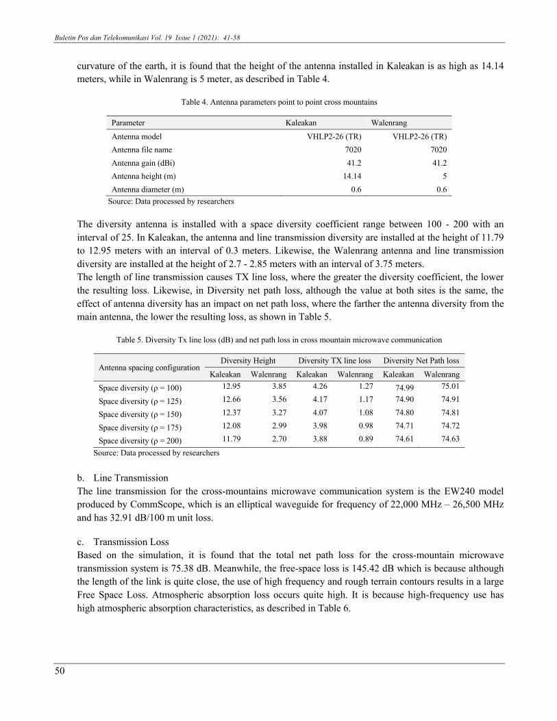
curvature of the earth, it is found that the height of the antenna installed in Kaleakan is as high as 14.14 meters, while in Walenrang is 5 meter, as described in Table 4.
Table 4. Antenna parameters point to point cross mountains
Parameter Kaleakan Walenrang
Antenna model VHLP2-26 (TR) VHLP2-26 (TR) Antenna file name 7020 7020 Antenna gain (dBi) 41.2 41.2 Antenna height (m) 14.14 5 Antenna diameter (m) 0.6 0.6
Source: Data processed by researchers
The diversity antenna is installed with a space diversity coefficient range between 100 - 200 with an interval of 25. In Kaleakan, the antenna and line transmission diversity are installed at the height of 11.79 to 12.95 meters with an interval of 0.3 meters. Likewise, the Walenrang antenna and line transmission diversity are installed at the height of 2.7 - 2.85 meters with an interval of 3.75 meters. The length of line transmission causes TX line loss, where the greater the diversity coefficient, the lower the resulting loss. Likewise, in Diversity net path loss, although the value at both sites is the same, the effect of antenna diversity has an impact on net path loss, where the farther the antenna diversity from the main antenna, the lower the resulting loss, as shown in Table 5.
Table 5. Diversity Tx line loss (dB) and net path loss in cross mountain microwave communication
Antenna spacing configuration Diversity Height Diversity TX line loss Diversity Net Path loss
Kaleakan Walenrang Kaleakan Walenrang Kaleakan Walenrang Space diversity (ρ = 100) 12.95 3.85 4.26 1.27 74.99 75.01
Space diversity (ρ = 125) 12.66 3.56 4.17 1.17 74.90 74.91
Space diversity (ρ = 150) 12.37 3.27 4.07 1.08 74.80 74.81
Space diversity (ρ = 175) 12.08 2.99 3.98 0.98 74.71 74.72
Space diversity (ρ = 200) 11.79 2.70 3.88 0.89 74.61 74.63
Source: Data processed by researchers
b. Line Transmission The line transmission for the cross-mountains microwave communication system is the EW240 model produced by CommScope, which is an elliptical waveguide for frequency of 22,000 MHz – 26,500 MHz and has 32.91 dB/100 m unit loss.
c. Transmission Loss Based on the simulation, it is found that the total net path loss for the cross-mountain microwave transmission system is 75.38 dB. Meanwhile, the free-space loss is 145.42 dB which is because although the length of the link is quite close, the use of high frequency and rough terrain contours results in a large Free Space Loss. Atmospheric absorption loss occurs quite high. It is because high-frequency use has high atmospheric absorption characteristics, as described in Table 6.

Comparative Analysis of Microwave Link Using Space and Hybrid Diversity Configuration on Mountain Topography Area (Ade Wahyudin, dkk)
51
Table 6. Transmission loss in cross-mountain microwave communications
Parameter Kaleakan Walenrang
TX line loss (dB) 4.65 1.65
Circulator branching loss (dB) 2 2 Free space loss (dB) 145.42 Atmospheric absorption loss (dB) 2,07 Net path loss (dB) 75.38 75.38
Source: Data processed by researchers
d. Parameter Radio The radio device used on the cross mountains microwave communication is the ML26E HP manufactured by Ericsson. The device uses the CQPSK modulation. This device is capable of radiating an EIRP of 52.55 dBm and has a threshold at the receiver of 10-6 BER with a level of -79 dBm, as described in Table 7.
Table 7. Radio parameters on cross mountains microwave communication
Parameter Kaleakan Walenrang
Radio model ML26E HP 17E1,raf ML26E HP 17E1,raf
Radio file name ml26e hp 17e1 ml26e hp 17e1
TX power (dBm) 18.00 18.00
Emission designator 28M6G7W 28M6G7W
EIRP (dBm) 52.55 55.55
RX threshold criteria 1E-6 BER 1E-6 BER
RX threshold level (dBm) -79.00 -79.00
Source: Data processed by researchers
e. Transmission Channel Frequency Settings The frequency channel used in point-to-point and space diversity uses a frequency of 26,173 MHz, vertical polarization in Kaleakan, and 25,165 MHz in Walenrang. While hybrid diversity configuration using two frequency channels. The frequency channel used for cross-mountain transmission system uses a frequency of 26,173 MHz and 25,277 MHz with vertical polarization in Pekajang Village while in Air Jukung Village using a frequency of 25,165 MHz and 26,285 MHz with vertical polarization.
3.5. Simulation Report
The last stage is to get a report from the simulations that have been carried out. The resulting reports include transmission summary reports and transmission detail reports.
Figure 5. Research flowchart
StartSite, Radio and Device
DataSite Configuration
Result and AnalysisEnd
Terrain Configutation
Radio Transmission Configuration
Simulation ReportConclusions
Digital Maps Configuration

Buletin Pos dan Telekomunikasi Vol. 19 Issue 1 (2021): 41-58
52
4. Result and Discussion
4.1. Point-to-Point Configuration
Figure 6. Point-to-point microwave radio transmission configuration over mountains
According to the simulation results, the fading margin on a cross-mountain microwave link using a point-to-point antenna reaches 21.62 dB. This is because the received signal is quite low at -57.38 dBm while the receiver threshold level on the radio device reaches -79 dBm. The result of the annual multipath availability is 99.98179%, and the annual multipath un-availability is 5742.79 seconds per year. Meanwhile, in rainy conditions, the annual multipath availability is 99.85763%, and the annual multipath un-availability is 748.27 minutes per year, as described in Table 8.
Table 8. Point to point microwave link performance on mountain ranges
Parameter Kaleakan Walenrang Receive signal (dBm) -57.38 -57.38
Thermal fade margin (dB) 21.62 21.62
Worst month multipath availability (%) 99.97189 99.97189
Worst month multipath unavailability (sec) 738.80 738.80
Annual multipath availability (%) 99.99089 99.99089
Annual multipath unavailability (sec) 2871.39 2871.39
Annual 2-way multipath availability (%) 99.98179 Annual 2-way multipath unavailability (sec) 5742.79 Polarization Vertical 0,01% rain rate (mm/hr) 79.70 Flat fade margin - rain (dB) 21.62 Rain attenuation (dB) 21.62 Annual rain availability (%) 99.87585 Annual rain unavailability (min) 652.56 Annual rain + multipath availability (%) 99.85763 Annual rain + multipath unavailability (min) 748.27
Source: Data processed by researchers

Comparative Analysis of Microwave Link Using Space and Hybrid Diversity Configuration on Mountain Topography Area (Ade Wahyudin, dkk)
53
4.2. Radio Transmission Configuration Microwave Space Diversity in Cross Mountains
Figure 7. Radio transmission configuration microwave space diversity in cross mountains
According to the simulation, the fading margin in the cross-mountain microwave communication system, the Kaleakan site is 22.01 dB - 22.39 dB, while the Walenrang site is 21.99 dB to 22.37 dB, as shown in table 10. The calculation of the fading margin is obtained from the reduction of the Received Signal Level by the Receiver Threshold, where the receiver threshold is based on the radio parameters shown in Table 9.
Table 9. Fade margin space diversity in cross mountains microwave communication
Antenna Spacing Configuration Kaleakan Walenrang
Space diversity (ρ = 100) 22.01 21.99
Space diversity (ρ = 125) 22.10 22.09
Space diversity (ρ = 150) 22.20 22.19
Space diversity (ρ = 175) 22.29 22.28
Space diversity (ρ = 200) 22.39 22.37 Source: Data processed by researchers
Table 10. Space diversity improvement factor in cross mountains microwave communication
Antenna Spacing Configuration SD Improvement factor
Desa Pekajang Desa Air Jukung
Space diversity (ρ = 100) 1.00 1.00
Space diversity (ρ = 125) 1.00 1.00
Space diversity (ρ = 150) 1.00 1.00
Space diversity (ρ = 175) 1.13 1.08
Space diversity (ρ = 200) 1.47 1.42
Source: Data processed by researchers
Then, the annual multipath availability in cross-mountain microwave communication systems has a value range of 99.98333% to 99.98943%, or in one year, there is a transmission failure on both uplink and downlink lines for 5255.53 seconds to 3332.48 seconds, such as described in Table 11. While it has the same annual multipath availability value in rainy conditions, this is due to the annual rain availability of 99.87938% and unavailability conditions for 721 to 671 minutes in one year, as in Table 12.

Buletin Pos dan Telekomunikasi Vol. 19 Issue 1 (2021): 41-58
54
Table 11. Availability and un-availability of space diversity in cross-mountain microwave communication
Antenna Spacing Configuration Annual 2-way multipath availability (%) Annual 2-way multipath unavailability (sec)
Space diversity (ρ = 100) 99.98333 5255.53 Space diversity (ρ = 125) 99.98370 5141.29 Space diversity (ρ = 150) 99.98405 5029.53 Space diversity (ρ = 175) 99.98590 4447.82 Space diversity (ρ = 200) 99.98943 3332.48
Source: Data processed by researchers
Table 12. Availability and un-availability + rain space diversity in cross mountain microwave communication
Antenna Spacing Configuration Flat fade margin - rain (dB)
Annual rain + multipath availability (%)
Annual rain + multipath unavailability (min)
Space diversity (ρ = 100) 21.99 99.86271 721.58 Space diversity (ρ = 125) 22.09 99.86394 715.11 Space diversity (ρ = 150) 22.19 99.86516 708.73 Space diversity (ρ = 175) 22.28 99.86782 694.72 Space diversity (ρ = 200) 22.37 99.87220 671.70
Source: Data processed by researchers
4.3. Radio Transmission Configuration Microwave Hybrid Diversity in Cross Mountains
Figure 8. Radio transmission configuration microwave space diversity in cross mountains
Based on the simulation results, the resulting fading margin hybrid diversity in the cross-mountain microwave communication system, the Kaleakan site is 21.99 dB - 22.37 dB while the Walenrang site is 21.99 dB to 22.37 dB, as shown in Table 13.
Table 13. Fade margin hybrid diversity in cross mountains microwave communication
Antenna Spacing Configuration Fade margin (dB)
Kaleakan Walenrang Hybrid diversity (ρ = 100) 21.99 21.99
Hybrid diversity (ρ = 125) 22.09 22.09 Hybrid diversity (ρ = 150) 22.19 22.19 Hybrid diversity (ρ = 175) 22.28 22.28 Hybrid diversity (ρ = 200) 22.37 22.37 Source: Data processed by researchers

Comparative Analysis of Microwave Link Using Space and Hybrid Diversity Configuration on Mountain Topography Area (Ade Wahyudin, dkk)
55
Table 14. Hybrid diversity improvement factor in cross-mountain microwave communication
Antenna Spacing Configuration SD Improvement Factor FD Improvement Factor Quad Diversity Improvement Factor
Kaleakan Walenrang Kaleakan Walenrang Kaleakan Walenrang Hybrid diversity (ρ = 100)
1.00 1.23 1.00 2.00
Hybrid diversity (ρ = 125) 1.00 1.26 1.00 2.00
Hybrid diversity (ρ = 150) 1.00 1.28 1.03 2.03
Hybrid diversity (ρ = 175) 1.08 1.31 1.05 2.13
Hybrid diversity (ρ = 200) 1.42 1.34 1.07 2.49
Source: Data processed by researchers
Then, the annual multipath availability in cross-water microwave communication systems has a value range of 99.98903% to 99.99122%, or in one year, there is a transmission failure on both uplink and downlink lines for 3458.99 seconds to 2769.79 seconds, such as is described in Table 15. While it has the same annual multipath availability in rainy conditions, this is due to the annual rain availability of 99.87938% and unavailability for 691 to 662 minutes in one year, as in Table 16.
Table 15. Availability and un-availability of space diversity in cross-mountain microwave communication
Antenna Spacing Configuration Annual 2-way multipath availability (%) Annual 2-way multipath unavailability (sec)
Hybrid diversity (ρ = 100) 99.98903 3458.99 Hybrid diversity (ρ = 125) 99.98942 3335.51 Hybrid diversity (ρ = 150) 99.98984 3205.56 Hybrid diversity (ρ = 175) 99.99036 3038.74 Hybrid diversity (ρ = 200) 99.99122 2769.79
Source: Data processed by researchers
Table 16. Availability and un-availability + rain space diversity in cross mountain microwave communication
Antenna Spacing Configuration Flat fade margin - rain (dB)
Annual rain + multipath availability (%)
Annual rain + multipath unavailability (min)
Hybrid diversity (ρ = 100) 21.99 99.86841 691.64 Hybrid diversity (ρ = 125) 22.09 99.86967 685.02 Hybrid diversity (ρ = 150) 22.19 99.87094 678.33 Hybrid diversity (ρ = 175) 22.28 99.87229 671.23 Hybrid diversity (ρ = 200) 22.37 99.87399 662.32
Source: Data processed by researchers
4.4. Discussion
In the mountains terrain, the fading margin of a point-to-point configuration produces 21.62 dB. This value results in the availability of 99.98179% or un-availability for 5742.79 seconds/year. This value does not meet the standards set by the ITU-R (ITU-T G.821), where for microwave communication with a distance of 10 km – 50 km, a minimum availability is 99.99%. So to solve it, the microwave communication system uses a diversity, space, and hybrid configuration approach.
In the microwave communication configuration using space and hybrid diversity, the fading margin is almost the same for all the spacing between antennas setting (ρ = 100 to ρ = 200). This is because some hybrid diversity configurations are looking for the best performance between system space or frequency diversity. Then, based on the simulation results, space diversity produces the best fading margin value in some

Buletin Pos dan Telekomunikasi Vol. 19 Issue 1 (2021): 41-58
56
conditions. Even though overall, the fading margin on both the space and the hybrid almost has the same value. Also, the further the space between antennas, the bigger the fading margin value, as shown in Figure 9.
Figure 9. Comparison of fading margin on space configuration and hybrid diversity in cross-mountain microwave communication
Overall, using the diversity configuration has not been able to produce a performance above the standard set by ITU. In space diversity with the closest spacing (ρ = 100), the availability is 99.98333% to 99.98943% or comparable to un-availability for 5255.53 to 3332.48 seconds per year and increases significantly in proportion to the distance between antennas. Even the hybrid diversity configuration has not been able to produce values above 99.99%, except at the farthest antenna distance, it results in the availability of up to 99.99122% or equivalent to un-availability for 2769.79 seconds per year at all antenna distances, as shown in figure 10. It is due to the use of high frequencies that are susceptible to attenuation, such as multipath and the influence of the atmosphere and hilly contour conditions that cause diffraction.
(a) (b)
Figure 10. Comparison of annual 2-way multipath availability (a) and unavailability (b) on space configuration and hybrid diversity in cross-mountain microwave communication
Even though it produces different meter values in rainy conditions, overall results in worse performance because none of the configurations produce the above standard conditions set by the ITU, as shown in Figures 11. Several solutions to overcome microwave communication quality problems are The worst thing in mountainous areas is to use a lower frequency or to use a repeater in the middle of the track.

Comparative Analysis of Microwave Link Using Space and Hybrid Diversity Configuration on Mountain Topography Area (Ade Wahyudin, dkk)
57
(a) (b)
Figure 11. Comparison of annual rain + multipath availability (a) and unavailability (b) configuration of space and hybrid diversity in cross-mountain microwave communication
5. Conclusion
Based on the results and discussion, it can be concluded that the microwave communication system can implement point-to-point configurations, space diversity, and hybrid diversity both across mountains. The fading margin of Cross-Mountain Microwave Communication with a point-to-point configuration produces a value of 21.62 dB. However, when using space diversity and hybrid diversity, it increases from 21.99 dB to 22.37 dB.
In the cross-mountain communication system using point-to-point configuration, result in the availability is 99.98179% or un-availability for 5742.79 seconds in one year. This value does not meet the standards set by the ITU-R (ITU-T G.821), where for communication with a distance of 10km - 50km, a minimum availability value must be 99.99%.
Overall, cross-mountain communication systems using diversity configurations have not been able to produce values above the standards set by the ITU. In space diversity with the closest antenna space (ρ = 100), the availability is 99.98333% to 99.98943% or comparable to un-availability for 5255.53 to 3332.48 seconds/year and increases significantly in proportion to the distance between antennas space. Even the hybrid diversity configuration has not been able to produce values above 99.99%, except at the farthest antenna distance, it results in the availability of up to 99.99122% or equivalent to un-availability for 2769.79 seconds per year at all antenna distances. 6. References Attamimi, S., & Rachman, R. (2014). Perancangan Jaringan Transmisi Gelombang Mikro Pada Link Site Mranggen 2 Dengan Site Pucang Gading.
Jurnal Teknologi Elektro, 5(2). https://doi.org/10.22441/jte.v5i2.764
Azhar, M., Pradana, Z. H., & Wahyudin, A. (2018). Analisa Perencanaan Backhaul Untuk Jaringan Long Term Evolution (LTE) Dikota Yogyakarta. Techno (Jurnal Fakultas Teknik, Universitas Muhammadiyah Purwokerto), 19(2), 103. https://doi.org/10.30595/techno.v19i2.3010
Badan Pusat Statistik. (2018). Statistik Telekomunikasi Indonesia. Badan Pusat Statistik.
Dewanti, I. E., Wahyudin, A., & Hikmaturrokhman, A. (2017). Analisis Perbandingan Passive Repeater Back-To-Back Antenna Dan Passive Repeater Plane Reflector Menggunakan Pathloss 5 . 0 Comparative Analysis of Passive Repeater Back-To-Back Passive Repeater Antenna and Plane Reflector Using the. Senatek (Seminar Nasional Teknik) 2017, 1–8.
Freeman, R. L. (2007). Radio System Design For Telecommunications (3rd ed.). John Wiley & Sons.
Hikmaturokhman, A., & Wahyudin, A. (2018). Perancangan Jaringan Gelombang Mikro Menggunakan Pathloss 5 (U. K. Usman (ed.)). Pustaka Ilmu.
Hikmaturokhman, A., Wahyudin, A., Yuchintya, A. S., & Nugraha, T. A. (2017). Comparison analysis of passive repeater links prediction using methods: Barnett Vigants & ITU models. Proceedings of 2017 4th International Conference on New Media Studies, CONMEDIA 2017, 2018-Janua, 142–147. https://doi.org/10.1109/CONMEDIA.2017.8266046
Hikmaturrokhman, A., & Wahyudin, A. (2018). Perancangan Jaringan Gelombang Mikro Menggunakan Pathloss 5 (Vol. 53, Issue 9). https://doi.org/10.1017/CBO9781107415324.004

Buletin Pos dan Telekomunikasi Vol. 19 Issue 1 (2021): 41-58
58
ITU-T. (2002). ITU - T Recommendation G.821 Series G: Transmission Systems And Media, Digital Systems And Networks.
Kementerian Komunikasi dan Informatika. (2013). Sekilas Palapa Ring. Kominfo.Go.Id. https://kominfo.go.id/content/detail/3298/sekilas-palapa-ring/0/palapa_ring
Kizer, G. (2013). Digital Microwave Communication Engineering Point-to-Point Microwave Systems. John Wiley & Sons. https://doi.org/10.1037/0003-066X.45.9.1018
Lehpamer, H. (2010). Microwave Transmission Networks Planning, Design and Deploymeny (3rd ed., Vol. 53, Issue 9). McGraw-Hill. https://doi.org/10.1017/CBO9781107415324.004
Oktaviasari, E., Wahyudin, A., & Hikmaturokhman, A. (2018). Analisis Perbandingan Interferensi Link Gelombang Mikro pada Daerah Urban dan Rural Menggunakan. Conference of Electrical Engineering, Telematics, Industrial Technology, and Creative Media, 1, 178–183.
Pradana, Z. H., & Wahyudin, A. (2018). Analisis Optimasi Space Diversity pada Link Microwave Menggunakan ITU Models. Jurnal Elektro Dan Telekomunikasi Terapan, 4(2), 586. https://doi.org/10.25124/jett.v4i2.1148
Pramono, S. (2014). Analisa Perencanaan Power Link Budget untuk Radio Microwave Point to Point Frekuensi 7 GHz ( Studi Kasus : Semarang ). Politeknik Negeri Semarang, Jurnal Teknik Elektro Terapan, 3(1), 27–31.
Rahmawati, Y. Y., & Wahyudin, A. (2018). Perancangan Jaringan Backhaul Sistem Transmisi Gelombang Mikro Digital Menggunakan Frequency Diversity dan Tanpa Diversity di Wilayah Kepulauan Riau. Techno (Jurnal Fakultas Teknik, Universitas Muhammadiyah Purwokerto), 19(2), 63. https://doi.org/10.30595/techno.v19i2.3178
Wahyudin, A., & Hikmaturokhman, A. (2021). Analysis of cross-ocean microwave communication systems using point-to-point, space diversity and hybrid diversity configurations. Journal of Communications, 16(8), 331–340. https://doi.org/10.12720/jcm.16.8.331-340
Winch, R. G. (1998). Telecommunication Transmission Systems, 2nd edition (2nd ed.). McGraw-Hill.