comparative analysis of 60 co intensity-modulated radiation therapy
TRANSCRIPT

IOP PUBLISHING PHYSICS IN MEDICINE AND BIOLOGY
Phys. Med. Biol. 53 (2008) 3175–3188 doi:10.1088/0031-9155/53/12/007
Comparative analysis of 60Co intensity-modulatedradiation therapy*
Christopher Fox1,2, H Edwin Romeijn2,3, Bart Lynch2, Chunhua Men3,Dionne M Aleman4,6 and James F Dempsey2,5,7
1 Sun Nuclear Corporation, 425-A Pineda Court, Melbourne, FL 32940, USA2 Department of Radiation Oncology, University of Florida, Gainesville, FL 32610-0385, USA3 Department of Industrial and Systems Engineering, University of Florida, Gainesville,FL 32611-6595, USA4 Department of Mechanical and Industrial Engineering, University of Toronto, Toronto, Ontario,Canada5 ViewRay Incorporated, 101 SE 2nd Place, Suite 201D, Gainesville, FL 32601, USA
E-mail: [email protected], [email protected], [email protected], [email protected],[email protected] and [email protected]
Received 29 January 2008, in final form 1 April 2008Published 27 May 2008Online at stacks.iop.org/PMB/53/3175
AbstractIn this study, we perform a scientific comparative analysis of using 60Co beamsin intensity-modulated radiation therapy (IMRT). In particular, we evaluatethe treatment plan quality obtained with (i) 6 MV, 18 MV and 60Co IMRT;(ii) different numbers of static multileaf collimator (MLC) delivered 60Cobeams and (iii) a helical tomotherapy 60Co beam geometry. We employa convex fluence map optimization (FMO) model, which allows for thecomparison of plan quality between different beam energies and configurationsfor a given case. A total of 25 clinical patient cases that each contain volumetricCT studies, primary and secondary delineated targets, and contoured structureswere studied: 5 head-and-neck (H&N), 5 prostate, 5 central nervous system(CNS), 5 breast and 5 lung cases. The DICOM plan data were anonymizedand exported to the University of Florida optimized radiation therapy (UFORT)treatment planning system. The FMO problem was solved for each case for5–71 equidistant beams as well as a helical geometry for H&N, prostate, CNSand lung cases, and for 3–7 equidistant beams in the upper hemisphere forbreast cases, all with 6 MV, 18 MV and 60Co dose models. In all cases, 95%of the target volumes received at least the prescribed dose with clinical sparingcriteria for critical organs being met for all structures that were not wholly or
* This work was supported by the National Science Foundation under grant no. DMI-0457394 and the NationalCancer Institute under grant no. R01 CA100636.6 The work of this author was supported by The Alliance for Graduate Education and the Professoriate and a GraduateResearch Fellowship of the National Science Foundation.7 This author owns stock in and is Chief Science Officer of ViewRay Incorporated and as such may benefit financiallyas a result of the outcomes of work or research reported in this manuscript.
0031-9155/08/123175+14$30.00 © 2008 Institute of Physics and Engineering in Medicine Printed in the UK 3175

3176 C Fox et al
partially contained within the target volume. Improvements in critical organsparing were found with an increasing number of equidistant 60Co beams,yet were marginal above 9 beams for H&N, prostate, CNS and lung. Breastcases produced similar plans for 3–7 beams. A helical 60Co beam geometryachieved similar plan quality as static plans with 11 equidistant 60Co beams.Furthermore, 18 MV plans were initially found not to provide the same targetcoverage as 6 MV and 60Co plans; however, adjusting the trade-offs in theoptimization model allowed equivalent target coverage for 18 MV. For planswith comparable target coverage, critical structure sparing was best achievedwith 6 MV beams followed closely by 60Co beams, with 18 MV beams requiringsignificantly increased dose to critical structures. In this paper, we report indetail on a representative set of results from these experiments. The results ofthe investigation demonstrate the potential for IMRT radiotherapy employingcommercially available 60Co sources and a double-focused MLC. Increasingthe number of equidistant beams beyond 9 was not observed to significantlyimprove target coverage or critical organ sparing and static plans were foundto produce comparable plans to those obtained using a helical tomotherapytreatment delivery when optimized using the same well-tuned convex FMOmodel. While previous studies have shown that 18 MV plans are equivalentto 6 MV for prostate IMRT, we found that the 18 MV beams actually requiredmore fluence to provide similar quality target coverage.
1. Introduction
Cobalt teletherapy units and linear accelerator systems (linacs) were introduced nearlysimultaneously in the early 1950s and emerged as rival technologies for external beam therapy.The first two 60Co units were installed in Canada in 1951 (Litt 2000) and the first clinicalmegavoltage (MV) linac was installed in London in 1952 (Bernier et al 2004, Thwaites andTuohy 2006), with the first patient treated with this machine in 1953. The deeply penetratingionizing photon beams provided by these devices quickly became the mainstay of radiationtherapy, allowing for the noninvasive treatment of deep-seated tumors. In particular, boththe linac and the cobalt teletherapy unit offered improved skin sparing and penetration overthe orthovoltage unit employed until that time. Initially, cobalt teletherapy became the mostwidespread form of external beam therapy. This was mainly due to the safety, reliability,precision and simplicity of these units, requiring little maintenance and technical expertise tooperate, as compared to the technologically intensive linacs. By the late 1960s, there wereapproximately 1700 external beam devices in the world and approximately 90% of them werecobalt therapy units (Hogstrom and Almond 2006). In the 1970s, major advances were madein the production of electron beams using linacs. Before the discovery and development ofintensity-modulated radiation therapy (IMRT), electron beams were demonstrated to providesuperior methods for treating cancer of the breast and the head-and-neck (H&N) (Hogstromand Almond 2006). This, combined with a lack of technical improvements for the cobaltunit (lack of multileaf collimator (or MLC) and digital readout, etc), gave the linac a clinicaladvantage over the cobalt unit for nearly three decades. By the late 1980s, over 90% oftherapy units in the US were linacs, and in the 1990s cobalt therapy units essentially vanishedin the US. During this time, great advances were made in beam delivery based on large-scaletreatment plan optimization, allowing the clinical application of IMRT using MLCs. With this

Comparative analysis of 60Co intensity-modulated radiation therapy 3177
advent of MLC-based IMRT, the advantage of combining photon and electron beams vanishedas IMRT was performed using only photon beams and could provide excellent treatment plansfor cancer of the breast and head-and-neck (Webb 2004). In fact, so did the advantage of high-energy MV photon beams, as it has been demonstrated that IMRT only requires low-energyphoton beams to produce high quality treatment plans, even for a deep-seated prostate tumorin exceptionally large patients (Pirzkall et al 2002, Sun and Ma 2006)).
Although low-energy photon beams have demonstrated efficacy for IMRT, cobalt unitshave other technical issues when compared with the linac (Laughlin et al 1986, Suit 1986).Historically, cobalt therapy systems were noted to suffer from four significant limitations:
(i) cobalt beams were noted to have a beam edge (or penumbra) that was not as sharp as thatof a photon beam that can be produced from a linac;
(ii) cobalt beams often created high surface doses which could result in skin reactions dueto low-energy contamination electrons (scattered from the source and collimators by thephoton beam) (Mora et al 1999);
(iii) the most powerful cobalt beams had a lower dose rate than linacs by approximately 60%(with a maximum output of ∼250 cGy min−1) and
(iv) cobalt beams are not as penetrating as higher (10–20) MV beams available on a linac.
These disadvantages, along with the ability of electron beams to produce curative treatmentplans for cancers of the breast and head-and-neck (in the pre-IMRT era), resulted in the eventualpreference for the linac in the 1970s and 1980s and the eventual demise of cobalt teletherapyas a leading technology in the developed world.
However, cobalt was not without its supporters. In 1986, Laughlin et al (1986) publisheda paper detailing the pros and cons of 60Co and called for a continued push in the technicaldevelopment of cobalt therapy. That call was reiterated in an editorial by (Suit 1986) in thesame journal issue, but went unheeded until now. Recently, development on a novel magneticresonance image-guided radiation therapy (MRIGRT) device has begun (RenaissanceTM
System 1000, ViewRay Incorporated, Gainesville, OH) by the authors of this manuscript.The device is designed to overcome all four of the above-mentioned limitations of cobalttherapy in the following manner:
(i) the penumbra of a linac with a MLC (which has been measured to be in the range of4–7 mm depending on manufacturer (Huq et al 2002, Kanagaki et al 2007, Langenet al 2005)) is actually comparable to that of a cobalt unit when a double-focused MLCis employed with a commercially available 2 cm diameter cobalt source (T1000, MDSNordion; see the results in this paper);
(ii) the magnetic field of the MRI eliminates contamination electrons and with it the possibilityof high surface doses and related skin reactions (Jursinic and Mackie 1996);
(iii) by utilizing three radiotherapy heads the MRIGRT device provides a competitive doserate that is higher than a standard linac 2 years after source install and
(iv) the penetration of a 60Co photon beam is not important with IMRT, which is supportedby the results of this manuscript.
Previous work (Laughlin et al 1986) has considered the characteristics and merits of beamenergies in the range 1–45 MV for conformal photon beams (non-IMRT) and demonstratedthat for 3- and 4-beam planning equivalent dose distributions can be achieved with 6, 10 and18 MV beams and clinical advantages associated with higher energy beams improve littlebeyond 4 MV. In the case of IMRT, most studies have demonstrated that 6 and 18 MV beamsproduce equivalent quality treatment plans (Pirzkall et al 2002, Sun and Ma 2006, Weisset al 2007), although Madani et al (2007) observe some differences depending on the dose

3178 C Fox et al
calculation method used. However, comparisons of 60Co and linac treatment planning forIMRT have not been published in the medical physics literature.
Consideration of the IMRT treatment setup must include not only the optimum beamquality but also a decision as to the number of beams and their orientation about the patient.This choice is often left to the discretion of the treatment center and is based on priorknowledge and experience. However, the fundamental question of the optimal number ofequidistant beams and beam orientation optimization is still under discussion in the literature,although several studies have shown a sharply declining marginal benefit of using more than10 equidistant beams for high-energy photon beam IMRT (see, e.g., Bortfeld et al (1990), Daset al (2003) and Stien et al (1997)). Additionally, rotating fan beams have been introducedthat utilize a helical treatment pattern by rotating the beam about a 360◦ gantry and translatingthe patient couch through it (Beavis 2004, Yang et al 1997). This effectively approximates thelimit of a large number of coplanar fan beams about the gantry for beam delivery.
The goal of this work is to investigate the use of different numbers of static multileafcollimator (MLC) delivered beams as well as a helical tomotherapy beam geometry in 60CoIMRT. Treatment plans with 5–71 equidistant 6 MV and 60Co beams are compared in termsof target coverage and organ sparing for H&N, prostate, CNS and lung cases, and 3–7equidistant beams restricted to the upper hemisphere for breast cases. In addition, a helicalbeam implementation is compared to static field plans for a 60Co beam modality for H&Ncases. Finally, 6 MV, 18 MV and 60Co beams were compared for a prostate case.
2. Materials and methods
Five patient cases for each of five typical IMRT treatment sites (H&N, prostate, CNS, breastand lung) were used in our study. H&N and CNS cases contained two targets, referredto as PTV1 and PTV2. For prostate cases, PTV1 contained the prostate gland plus an8 mm isotropic margin to allow for spatial uncertainties arising from setup errors and physicalmotions during treatment. Similarly, PTV2 contained the prostate gland and seminal vesiclesand an 8 mm isotropic margin. For lung cases, margins were added according to the tumorlocation. A symmetric margin of 0.5 cm was added to upper lobe tumors while to tumors in thelower lobe a 0.5 cm transversal and 1 cm craniocaudal margin was applied (as in the work byLeter et al (2005)). Targets for breast cases were designated as in the work by Hong et al(1999), where PTV1 comprised the tumor bed and PTV2 the breast tissue plus nodes with a1 cm margin in the posterior direction and 2 cm in the superior and inferior. The PTV2 targetwas extended to the body contour in the anterior direction.
Prescription doses of 73.8 and 54 Gy were assigned to PTV1 and PTV2, respectively,for H&N, prostate and CNS cases. For lung cases, PTV1 and PTV2 were prescribed 70and 50 Gy, respectively, and in breast cases the prescription doses for PTV1 and PTV2 were60 and 54 Gy, respectively. Target coverage of 95% volume receiving the prescription dose(D95% � DRx) with the maximum dose limited to 1.1 × DRx was deemed acceptable. Thetolerance doses applied to critical structures are shown in table 1 and are given as maximumtolerance dose allowed or constraints on the dose per volume fraction.
Anonymized DICOM volumetric CT data and delineated targets and structures for all25 cases were imported into the University of Florida optimized radiation therapy (UFORT)treatment planning decision support system (TPDSS). This treatment planning system hasbeen commissioned for use with 6 MV, 18 MV and 60Co beamlet models from a Varian2100C/D linac and a Theratronics 1000C cobalt unit (with a commercially available cobaltsource (13,000 Ci 2 cm, MDS Nordion) at a 1 m isocenter with a double-focused MLC withits furthest side at 50 cm from the source). These models were fitted to published data and

Comparative analysis of 60Co intensity-modulated radiation therapy 3179
Table 1. Tolerance criteria for critical structures.
Organ Criterion Organ Criterion
Retina/eye <45 Gy Eye lens <12 GyOptic nerve <50 Gy Optic chiasm <55 GyBrain stem <55 Gy Spinal cord <45 GyParotid gland <30 Gy at 50% Submandibular gland <30 Gy at 50%Rectum <60 Gy at 30% Bladder <60 Gy at 30%Skin <60 Gy Mandible <70 GyIndividual lung (breast) <20 Gy at 20% Total lung (lung) <40 Gy at 40%Individual lung (breast) Mean < 15 Gy Total lung (lung) Mean < 15 Gy
validated with radiochromic film of 1 × 1 cm2 beamlets formed by the accelerator jaws for6 and 18 MV and by a Cerrobend block for 60Co. Data were measured using the methodsdescribed by Dempsey et al (1999), (2000). For the dose calculations, the CT and structuredata were mapped to an isotropic grid. Dempsey et al (2005) used a Fourier analysis todetermine the required resolution for 6 MV beams. In that paper, the 80–20% penumbra forthe 6 MV beam was 2.25 mm and the required resolution for 1% accuracy was found to be2.5 mm. In addition, we found that the 80–20% penumbra for 60Co was 4.5 mm and therequired resolution for 1% accuracy was 4–5 mm. Hence, in order to ensure that all relevantinformation in the dose distribution was captured we employed voxels of size 2.5 × 2.5 ×2.5 mm3 for 6 and 18 MV and 4 × 4 × 4 mm3 for 60Co. The UFORT TPDSS uses apoint-in-polygon technique to associate structures with voxels in the grid and a combinationof stereographic projection and three-dimensional ray-tracing is used to determine densityscaled depths (see Fox et al (2006)) to account for heterogeneities and establish thosevoxels intersected by each beamlet that traverses the target volume. Relative intensitiesat intersected voxels from each beamlet are determined, yielding dose deposition coefficientsDijs , representing the dose deposited per unit intensity from beamlet i to voxel j containedwithin structure s. These coefficients are then input into a fluence map optimization (FMO)model. As is standard in treatment plan optimization models, the dose djs deposited in avoxel j contained within structure s is the result of the superposition of the intensity-weightedbeamlet dose depositions, formally given by the linear expression
djs =∑
i
Dijsxi
where xi is the (nonnegative) intensity or weighting factor associated with beamlet i. Our FMOmodel (see, e.g., Romeijn et al (2003), (2004) and Tsien et al (2003)) is an analytic nonlinearconvex model that employs voxel-based penalty functions. In particular, the objective functionis formulated as
f =∑
s
∑
j
(α+
s max{djs − t+
s , 0}n+
s + α−s max{t−s − djs, 0}n−
s
)
where, for each structure s, α+s and α−
s are the importance weights assigned to overdosingand underdosing, t+
s and t−s are the thresholds associated with overdosing and underdosing,and n+
s and n−s are powers that ensure that the objective function value f is adversely and
disproportionally affected as the dose moves away from the threshold values. Typically, bothoverdosing and underdosing penalties are included for targets while only overdosing penaltiesare included for critical structures. Targets are assigned the highest importance in the FMOmodel to ensure that the target coverage criteria are met, which is particularly important whenoverlap of targets and critical structures occurs. Similar tuning parameters were used for each

3180 C Fox et al
case with minor adjustments to improve target coverage and structure sparing as required. Theoptimal intensities of the available beamlets are then determined by optimizing the problem toprovide a fluence map that gives a high-quality dose distribution satisfying the desired clinicalcriteria as described below.
FMO problems were solved to obtain treatment plans for H&N, prostate, CNS and lungcases using 5, 7, 9, 11, 17, 35 and 71 equidistant beam angles. Breast cases were restrictedto a 180◦ arc above the breast to remove beamlets that enter the posterior to reach the tumor,and FMO problems were solved for 3, 5 and 7 equidistant beams. Plan quality was assessedvia dose–volume histogram (DVH) and spatial dose distribution evaluation. A comparison ofthe plan quality between the 6 MV, 18 MV and 60Co was performed and the impact of varyingthe number of equidistant coplanar beams on target coverage and critical structure sparinginvestigated. A helical scanning treatment beam was implemented in the UFORT TPDSSwith the 6 MV and 60Co beam models. A maximum collimator opening of 40 × 2 cm2 wasallowed with bixel size of 1 × 1 cm2 and pitch 0.5. The start and end point of the heliceswas established from the limits of targets in the cranium–caudal orientation with an additionalmargin of 1 cm.
The convex FMO model was solved by employing a projected gradient algorithm withArmijo line search (Kelley 1987). This yields a fast method that produces excellent targetcoverage and organ sparing. Our implementation of the projected gradient algorithm proceedsas follows. In a given iteration, k, with current solution x(k), the next solution is given by
x(k+1) = max{x(k) − λ∗∇fk, 0}where ∇fk is the gradient of f evaluated at x(k) and λ∗ is found by a search along theprojected path max{x(k) − λ∇fk, 0} parameterized by the nonnegative step length λ. Thesearch direction, being the negative of the gradient of f at the current solution, is a descentdirection so that the result of the line search is a solution with a lower (i.e., improved)objective function value (see figure 1). The performance of the algorithm depends greatly onthe step length. If the step length is too short the convergence of the algorithm will require alarge number of iterations and will therefore be slow. On the other hand, if the step size is toolarge the optimal solution may be overshot, producing an insufficient reduction in the objectivefunction in each step, again preventing fast convergence. In each iteration, a good step sizecan be obtained by (i) trying several test candidate values for λ and (ii) choosing the onethat provides the largest improvement in objective function value. The Armijo line searchmethod determines the step size by iteratively stepping backwards from a maximum step sizealong the search direction until a solution is found that attains a reduction in objective functionvalue. Finally, the leaf-sequencing algorithm of Kamath et al (2003) was applied to the fluencemaps obtained by the FMO to determine the number of MLC-shaped apertures required tosuccessfully deliver the fluence map.
3. Results and discussion
3.1. 60Co beamlet analysis
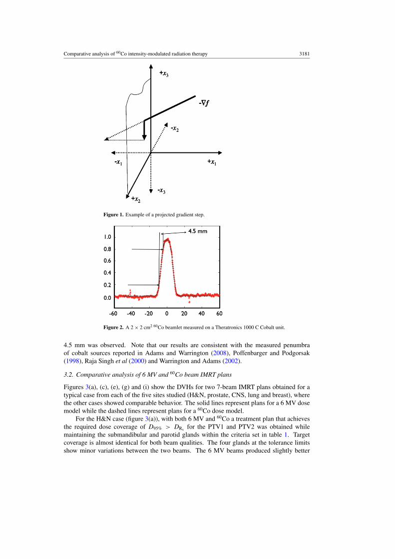
Figure 2 shows a profile of the radiochromic film measurement of a 2 × 2 cm2 60Co beamletmeasured on a Theratronics 1000C Cobalt unit at 0.5 cm depth in a 30 × 30 cm2 solidwater phantom at 100 cm source to surface distance using a divergent 10 cm thick Cerrobendcollimator with its distal end at 50 cm from the source. The beamlet was measured on thecentral axis; however, the cobalt source has a very even energy spectrum and no flatteningfilter so that the off-axis beamlets are very similar. An 80–20% penumbra distance of
Comparative analysis of 60Co intensity-modulated radiation therapy 3181
Figure 1. Example of a projected gradient step.
Figure 2. A 2 × 2 cm2 60Co beamlet measured on a Theratronics 1000 C Cobalt unit.
4.5 mm was observed. Note that our results are consistent with the measured penumbraof cobalt sources reported in Adams and Warrington (2008), Poffenbarger and Podgorsak(1998), Raja Singh et al (2000) and Warrington and Adams (2002).
3.2. Comparative analysis of 6 MV and 60Co beam IMRT plans
Figures 3(a), (c), (e), (g) and (i) show the DVHs for two 7-beam IMRT plans obtained for atypical case from each of the five sites studied (H&N, prostate, CNS, lung and breast), wherethe other cases showed comparable behavior. The solid lines represent plans for a 6 MV dosemodel while the dashed lines represent plans for a 60Co dose model.
For the H&N case (figure 3(a)), with both 6 MV and 60Co a treatment plan that achievesthe required dose coverage of D95% > DRx for the PTV1 and PTV2 was obtained whilemaintaining the submandibular and parotid glands within the criteria set in table 1. Targetcoverage is almost identical for both beam qualities. The four glands at the tolerance limitsshow minor variations between the two beams. The 6 MV beams produced slightly better

3182 C Fox et al
(a) (b)
(c) (d)
(e) (f)
Figure 3. DVHs for typical clinical cases. Parts (a), (c) and (e) show a comparison of 6 MV(solid) and 60Co (dashed) for 7 equidistant beams for H&N, prostate and CNS cases. Parts (b), (d)and (f) compare 5 (dotted), 9 (dashed) and 71 (solid) equidistant beams for the 60Co dose modelfor H&N, prostate and CNS cases. Parts (g) and (i) show a comparison of 6 MV (solid) and 60Co(dashed) for 7 equidistant beams for a lung case and 7 equidistant beams in the upper hemispherefor a breast case. Part (h) compares 5 (dotted), 9 (dashed) and 71 (solid) equidistant beams for the60Co dose model for a lung case, and part (j) compares 3 (dashed) and 5 (solid) equidistant beamsin the upper hemisphere for the 60Co dose model for a breast case.
sparing for left parotid and submandibular glands, at the sparing criterion condition, while60Co showed improved results for the right submandibular gland. These differences were not

Comparative analysis of 60Co intensity-modulated radiation therapy 3183
(g)
(i)
(h)
(j)
Figure 3. (Continued.)
deemed clinically significant and can be attributed to differences in the trade-offs made bythe FMO model. The DVH above 30 Gy is observed to decrease more rapidly for 60Co. At50 Gy, the DVH for 60Co is 3–4% lower compared to 6 MV and is most likely the result ofthe FMO models ability to take advantage of the reduced exit dose associated with the lowerpenetrability of the 60Co beam.
For the prostate case (figure 3(c)), equivalent target coverage was observed with both6 MV and 60Co for 7-beam plans. Below 30 Gy, the rectum is observed to receive ∼2–3 Gyless per volume than with 6 MV with the urinary bladder receiving approximately the samedose for each beam quality below 30 Gy. At the tolerance limits (<30% at 60 Gy), the dosefrom both modalities is the same for the urinary bladder and rectum. The lower maximumdose observed in the bladder and rectum using 60Co results from the higher attenuation of thebeam compared to 6 MV.
CNS cases are the simplest to solve, primarily due to the lack of proximity of the targetsto critical structures. Figure 3(e) shows that the required target coverage of D95% > DRx isachieved for both cases with only minor variations for 7-beam plans.
Figures 3(g) and (i) show a similar pattern for the lung and breast cases, respectively. Inaddition, for the breast case the mean dose to total lung was virtually identical at about 11 Gyfor both 6 MV and 60Co, while for the lung case marginally lower mean dose to both lungswas observed for 6 MV than for 60Co (about 10 versus 11 Gy for right lung and about 2 versus

3184 C Fox et al
2.5 Gy for left lung), but all observed mean lung doses were well below the tolerance limit.In summary, in both cases plan quality is similar between the 6 MV and 60Co modalities with7 beams.
3.3. Comparative analysis of varying the number of beams
Figures 3(b), (d), (f), (h) and (j) show the DVHs for IMRT plans obtained for a typical casefrom each of the five sites with different numbers of equidistant 60Co beams; the other casesexhibited similar behavior. In particular, in figures 3(b), (d), (f) and (h) (H&N, prostate,CNS and lung, respectively) the dotted lines correspond to 5-beam plans, the dashed lines to9-beam plans and the solid lines to 71-beam plans, while in figure 3(j) (breast) the dashedlines correspond to a 3-beam plan while the solid lines correspond to a 5-beam plan.
For the H&N case (figure 3(b)), good target coverage is observed with as few as fiveequidistant coplanar beams while the sparing criteria given in table 1 are maintained. Thethreshold of 95% target volume receiving the prescription dose is attained for the PTV1 andPTV2 with 5, 9 and 71 beams. The PTV1 coverage is the same for each set of equidistantbeams. However, the hot spot of the PTV2 at 20% volume improves by ∼5% between the 5-and 9-beam plans. Further increasing the number of beams shows only minor improvementsin the hot spot of the PTV2. Gland coverage shows a similar trend at 30 Gy with a reductionin the dose per volume of 3–10% when the number of beams is increased from 5 to 9beams. Increasing the number of beams up to 71 shows little change as compared to 9 beams.Figure 4 illustrates the dose distributions obtained for 7 and 71 beams from the 6 MV and60Co dose models. Only minor variations are observed between the two treatment modalities,and similar dose distributions for targets and critical structures were observed for 7 and 71beams.
As for the H&N case, the prostate plans demonstrate similar coverage of the PTV1 andPTV2 using 5, 9 and 71 beams (figure 3(d)). The dose to the urinary bladder and rectumis below accepted tolerances of 30% volume to receive less than 60 Gy for all three beamnumbers. Below 40 Gy a marked increase in dose to critical structures is observed when thenumber of beams is decreased. The 5-beam plan results in ∼5 Gy higher dose to 30% of therectum volume as compared to the 9- and 71-beam plans, for which the corresponding dose is20 Gy. The dose distribution of the skin varies considerably with changing number of beams.The 71-beam plan gives a lower dose to a larger percentage of the skin than the 5-beam plan:with the former plan 35% receives in excess of 10 Gy and about 3% in excess of 30 Gy, whilewith the latter plan only 20% of the skin receives in excess of 10 Gy and about 9% in excessof 30 Gy. This is likely the result of spreading the incident dose over a larger surface areawith more beams. Figure 5 illustrates the dose distributions obtained for 7 and 71 beams fromthe 6 MV and 60Co dose models. As for the H&N case, the variations observed between boththe treatment modalities are small and clinically comparable dose distributions for targets andcritical structures are obtained with 7 and 71 beams.
For both the CNS and the lung cases (figures 3(f) and (h)) only marginal improvementsare observed when the number of beams increases from 5 to 9. For the lung case, the meandose to either lung is virtually independent of the number of beams at 10–11 Gy for the rightlung and <3 Gy for the left lung. Overall, all criteria are well within the tolerances and littlefurther improvements are seen in the 71-beam plans over the 9-beam plans.
Finally, figure 3(j) shows the DVHs for 3-beam and a 5-beam 60Co breast plan. (Notethat beams for breast cases are restricted to a 180◦ arc above the breast tissue.) Comparingthese DVHs with figure 3(i), which shows a 7-beam plan, the total lung dose is observed tofall off faster as the number of beams increases. In each case, the maximum dose received to

Comparative analysis of 60Co intensity-modulated radiation therapy 3185
(a) (b)
(c) (d)
Figure 4. Deliverable IMRT axial isodose distributions for a H&N IMRT case. Parts (a) and(b) show 7-beam dose distributions for 6 MV and 60Co, respectively. Parts (c) and (d) are 71-beamdose distributions for 6 MV and 60Co, respectively. Shown are PTV1 (red) and PTV2 (dark blue)as well as the parotid glands (yellow), mandible (light green), spinal cord (light blue) and skin(bright green). Isodose curves are shown for 73.8, 60, 54, 45, 30 and 10 Gy.
the total lung is 60 Gy, the mean dose to lung is below the threshold at about 11–13 Gy, andthe tolerance limit of no more than 20% lung volume receiving in excess of 40 Gy is also met.
3.4. Comparative analysis of 6 MV, 18 MV and 60Co IMRT for prostate
Figure 6(a) shows an 18 MV dose model applied to a prostate case compared to 6 MV and60Co plans for the same case. The 18 MV beam model plan achieves the sparing criteria givenin table 1 for the urinary bladder and rectum and the coverage of PTV1 and PTV2 attains the95% volume receiving the prescription dose. However, the falloff in both the PTV2 and PTV1is less sharp with the 18 MV beam and additional tuning of the objective function parametersproduced little improvement and showed a marked increase of the rectum and urinary doseper volume around the 40% mark. The urinary bladder receives a consistently higher doseper volume with the 18 MV model, reaching a maximum of 20% volume having 20 Gy abovethat observed with the 6 MV case. This was also the case for the skin and parts of the rectum.
3.5. Comparative analysis of helical and static 60Co for H&N
Figure 6(b) shows a H&N plan obtained using a helical 60Co beam scanning pattern for thetreatment delivery (dotted lines) as well as a plan for the same patient obtained with 11 staticequidistant 60Co beams (solid lines). Target coverage and critical structure sparing criteriaare maintained for both plans. The target DVHs are almost identical, with the 11-beam static

3186 C Fox et al
(a) (b)
(c) (d)
Figure 5. Deliverable IMRT axial isodose distributions for a prostate IMRT case. Parts (a) and(b) show 7-beam dose distributions for 6 MV and 60Co, respectively. Parts (c) and (d) are 71-beamdose distributions for 6 MV and 60Co, respectively. Shown are PTV1 (red) and PTV2 (dark blue) aswell as bladder (yellow), rectum (brown), femoral heads (purple) and skin (bright green). Isodosecurves are shown for 73.8, 60, 54, 45, 30 and 10 Gy.
(a) (b)
Figure 6. (a) Comparison of an 18 MV (solid), 6 MV (dashed) and 60Co (dotted) dose model fora static 11-beam prostate plan. (b) Comparison of a static 11-beam 60Co (solid line) plan to thatof a helical 60Co (dotted line) plan for a H&N case.
plan showing a maximum divergence at the 15% volume level of 2 Gy for PTV2 and 1 Gy forPTV1, while the critical structure DVHs are virtually indistinguishable from one another.
3.6. Number of apertures
Finally, the leaf-sequencing algorithm was applied to the 25 cases investigated. To illustratethese results, table 2 shows, for a single case for each of the five sites and for both 6 MV and

Comparative analysis of 60Co intensity-modulated radiation therapy 3187
Table 2. Number of apertures required for typical cases.
H&N Prostate CNS Lung Breast
Number of beams 6 MV 60Co 6 MV 60Co 6 MV 60Co 6 MV 60Co 6 MV 60Co
3 89 895 164 150 130 135 108 107 104 107 157 1377 226 224 167 209 150 151 257 276 192 1809 283 316 219 238 188 195 328 35311 354 374 282 283 233 237 409 43217 504 537 397 480 346 358 630 66235 1014 1178 890 965 788 770 1249 138571 2330 2455 1743 1976 1623 1569 2561 2969
60Co beams, the number of apertures required to deliver the fluence map obtained from theFMO using the leaf-sequencing algorithm. The number of apertures varied from ∼90 for a3-beam breast plan up to ∼3000 for a 71-beam lung plan. For typical 7-beam plans, the H&Ncases required on the order of 225 apertures, compared to approximately 200 for prostate, 150for CNS and 275 for lung. In general, the number of apertures required increased linearlywith the number of beams for all sites and for both beam qualities. No trend was observedbetween the target volume and aperture number. Finally, fluence maps that contain a largernumber of gradient changes across the profile generally require a larger number of aperturesto successfully deliver the FMO fluence map using a MLC.
4. Conclusions
The data presented demonstrates that excellent plan quality for IMRT using inverse treatmentplanning can be achieved with low numbers of equidistant beams, with little gain fromextending beam numbers beyond 9 beams in terms of target coverage and critical organsparing. We also demonstrate the feasibility of employing commercial 60Co sources with adivergent MLC for IMRT and show that nearly identical plans can be achieved when comparedto 6 MV IMRT. We therefore conclude that the common assumption that the 60Co penumbrais inferior to linac penumbra for MLC-based IMRT is not supported by the literature (see, e.g.,Huq et al (2002), Kanagaki et al (2007), Langen et al (2005) or the findings of this study.
References
Adams E J and Warrington A P 2008 A comparison between cobalt and linear accelerator-based treatment plans forconformal and intensity-modulated radiotherapy Br. J. Radiol. 81 304–10
Beavis A W 2004 Is tomotherapy the future of IMRT? Br. J. Radiol. 77 285–95Bernier J, Hall E J and Giaccia A 2004 Radiation oncology: a century of achievements Nature Rev. Cancer 4 737–47Bortfeld T, Burkelbach J, Boesecke R and Schlegel W 1990 Methods of image reconstruction from projections applied
to conformal radiotherapy Phys. Med. Biol. 25 435–43Das S, Cullip T, Tracton G, Chang A, Marks L, Anscher M and Rosenman J 2003 Beam orientation selection for
intensity-modulated radiation therapy based on target equivalent uniform dose maximization Int. J. Radiat.Oncol. Biol. Phys. 55 215–24
Dempsey J F, Low D A, Kirov A S and Williamson J F 1999 Quantitative optical densitometry with scanning-laserfilm digitizers Med. Phys. 26 1721–31
Dempsey J F, Low D A, Mutic S, Markman J, Kirov A S, Nussbaum G H and Williamson J F 2000 Validation of aprecision radiochromic film dosimetry system for quantitative two-dimensional imaging of acute exposure dosedistributions Med. Phys. 27 2462–75

3188 C Fox et al
Dempsey J F, Romeijn H E, Li J G, Low D A and Palta J R 2005 A Fourier analysis of the dose grid resolutionrequired for accurate IMRT fluence map optimization Med. Phys. 32 380–8
Fox C, Romeijn H E and Dempsey J F 2006 Fast voxel and polygon ray-tracing algorithms in IMRT treatmentplanning Med. Phys. 33 1364–71
Hogstrom K R and Almond P R 2006 Review of electron beam therapy physics Phys. Med. Biol. 51 R455–89Hong L, Hunt M, Chui C, Spirou S, Forester K, Lee H, Yahalom J, Kutcher G J and McCormick B 1999 Intensity-
modulated tangential beam irradiation of the intact breast Int. J. Radiat. Oncol. Biol. Phys. 44 1155–64Huq M S, Das I J, Steinberg T and Galvin J M 2002 A dosimetric comparison of various multileaf collimators Phys.
Med. Biol. 47 N159–70Jursinic P A and Mackie T R 1996 Characteristics of secondary electrons produced by 6, 10 and 24 MV x-ray beams
Phys. Med. Biol. 41 1499–509Kamath S, Sahni S, Li J, Palta J and Ranka S 2003 Leaf sequencing algorithms for segmented multileaf collimation
Phys. Med. Biol. 48 307–24Kanagaki B, Read P W, Molloy J A, Larner J M and Sheng K 2007 A motion phantom study on helical tomotherapy:
the dosimetric impacts of delivery technique and motion Phys. Med. Biol. 52 243–55Kelley C T 1987 Iterative Methods in Optimization (Philadelphia: SIAM)Langen K M, Meeks S L, Poole D O, Wagner T H, Willoughby T R, Zeidan O A, Kupelian P A, Ruchala K J
and Oliveira G H 2005 Evaluation of a diode array for QA measurements on a helical tomotherapy unit Med.Phys. 32 3424–30
Laughlin J S, Mohan R and Kutcher G J 1986 Choice of optimum megavoltage for accelerators for photon beamtreatment Int. J. Radiat. Oncol. Biol. Phys. 12 1551–7
Leter E M, Cademartiri F, Levendag P C, Flohr T, Stam H and Nowak P J 2005 Four-dimensional multi slice computedtomography for determination of respiratory lung tumor motion in conformal radiotherapy Int. J. Radiat. Oncol.Biol. Phys. 62 888–92
Litt P 2000 Isotopes and Innovation: MDS Nordion’s First Fifty Years, 1946–1996 (Montreal: McGill-QueensUniversity Press)
Madani I, Vanderstraeten B, Bral S, Coghe M, De Gersem W, De Wagter C, Thierens H and De Neve W 2007Comparison of 6 MV and 18 MV photons for IMRT treatment of lung cancer Radiother. Oncol. 82 63–9
Mora G M, Maio A and Rogers D W O 1999 Monte Carlo simulation of a typical 60 Co therapy source Med.Phys. 26 2494–502
Pirzkall A, Carol M P, Pickett B, Xia P, Roach M III and Verhey L J 2002 The effect of beam energy and number offields on photon-based IMRT for deep-seated targets Int. J. Radiat. Oncol. Biol. Phys. 53 434–42
Poffenbarger B A and Podgorsak E B 1998 Viability of an isocentric cobalt-60 teletherapy unit for stereotacticradiosurgery Med. Phys. 25 1935–43
Raja Singh R, Ravindran P, Nizin P S and Ayyangar K 2000 Dosimetric study of the narrow beams of 60Co teletherapyunit for stereotactic radiosurgery Med. Dosim. 25 163–9
Romeijn H E, Ahuja R K, Dempsey J F, Kumar A and Li J G 2003 A novel linear programming approach to fluencemap optimization for intensity modulated radiation therapy treatment planning Phys. Med. Biol. 48 3521–42
Romeijn H E, Dempsey J F and Li J G 2004 A unifying framework for multi-criteria fluence map optimization modelsPhys. Med. Biol. 49 1991–2013
Stien J, Mohan R, Wang X-H, Bortfeld T, Wu Q, Preiser K, Ling C C and Schlegel W 1997 Number and orientationsof beams in intensity-modulated radiation treatments Med. Phys. 24 149–60
Suit H 1986 What’s the optimum choice? Int. J. Radiat. Oncol. Biol. Phys. 12 1711–2Sun M and Ma L 2006 Treatments of exceptionally large prostate cancer patients with low-energy intensity-modulated
photons J. Appl. Clin. Med. Phys. 7 43–9Thwaites D I and Tuohy J B 2006 Back to the future: the history and development of the clinical linear accelerator
Phys. Med. Biol. 51 R343–62Tsien C, Eisbruch A, McShan D, Kessler M, Marsh R and Fraass B 2003 Intensity-modulated radiation therapy (IMRT)
for locally advanced paranasal sinus tumors: incorporating clinical decisions in the optimization process Int.J. Radiat. Oncol. Biol. Phys. 55 776–84
Warrington A P and Adams E J 2002 Cobalt 60 teletherapy for cancer: a revived treatment modality for the 21stcentury IEE Seminar on Appropriate Medical Technology for Developing Countries
Webb S 2004 Contemporary IMRT: Developing Physics and Clinical Implementation (Madison, WI: AdvancedMedical Publishing)
Weiss E, Siebers J V and Keall P J 2007 An analysis of 6-MV versus 18-MV photon energy plans for intensity-modulated radiation therapy (IMRT) of lung cancer Radiother. Oncol. 82 55–62
Yang J, Mackie T R, Reckwerdt P, Deasy J O and Thomadsen B R 1997 An investigation of tomotherapy beamdelivery Med. Phys. 24 425–36