compalarm a - microener interesting feature of the compalarm a, ... fi rst out is applicable to the...
TRANSCRIPT
2
GENERAL
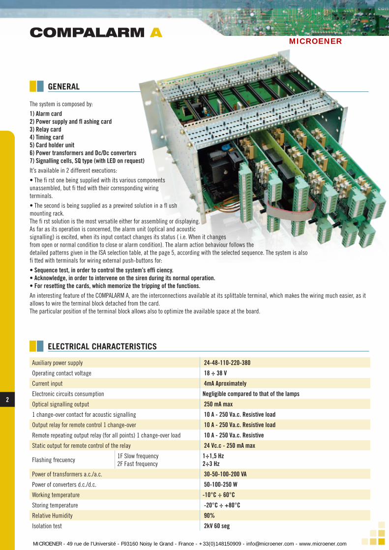
The system is composed by:
1) Alarm card2) Power supply and fl ashing card3) Relay card4) Timing card5) Card holder unit6) Power transformers and Dc/Dc converters7) Signalling cells, SQ type (with LED on request)It’s available in 2 different executions:
• The fi rst one being supplied with its various components unassembled, but fi tted with their corresponding wiring terminals.
• The second is being supplied as a prewired solution in a fl ush mounting rack.The fi rst solution is the most versatile either for assembling or displaying.As far as its operation is concerned, the alarm unit (optical and acoustic signalling) is excited, when its input contact changes its status ( i.e. When it changes from open or normal condition to close or alarm condition). The alarm action behaviour follows the detailed patterns given in the ISA selection table, at the page 5, according with the selected sequence. The system is also fi tted with terminals for wiring external push-buttons for:
• Sequence test, in order to control the system’s effi ciency.• Acknowledge, in order to intervene on the siren during its normal operation.• For resetting the cards, which memorize the tripping of the functions.An interesting feature of the COMPALARM A, are the interconnections available at its splittable terminal, which makes the wiring much easier, as it allows to wire the terminal block detached from the card.The particular position of the terminal block allows also to optimize the available space at the board.
Auxiliary power supply 24-48-110-220-380
Operating contact voltage 18 ÷ 38 V
Current input 4mA Aproximately
Electronic circuits consumption Negligible compared to that of the lamps
Optical signalling output 250 mA max
1 change-over contact for acoustic signalling 10 A - 250 Va.c. Resistive load
Output relay for remote control 1 change-over 10 A - 250 Va.c. Resistive load
Remote repeating output relay (for all points) 1 change-over load 10 A - 250 Va.c. Resistive
Static output for remote control of the relay 24 Vc.c - 250 mA max
Flashing frecuency1F Slow frequency2F Fast frequency
1÷1,5 Hz2÷3 Hz
Power of transformers a.c./a.c. 30-50-100-200 VA
Power of converters d.c./d.c. 50-100-250 W
Working temperature -10°C ÷ 60°C
Storing temperature -20°C ÷ +80°C
Relative Humidity 90%
Isolation test 2kV 60 seg
COMPALARM A
ELECTRICAL CHARACTERISTICS
MICROENER - 49 rue de l'Université - F93160 Noisy le Grand - France - +33(0)148150909 - [email protected] - www.microener.com
MICROENER

3 3
Type ofsignal
Normalconditions
Alarmcondition
Return tonormal
conditionsAfter reset
Push buttonsrequired
ISA-RP181 ISA-S18.1Persisting
AlarmMomentary
Alarm
Optical Off Flashing On Off Off -
Acoustic Silent Blows Silent Silent Silent -
Optical Off Blows* On - Off -
Acoustic Silent Blows* Silent - Silent -
Optical Off On* On - Off -
Acoustic Silent Blows* Silent - Silent -
Optical Off Flashing fast On Flashing slow Flashing slow Off
Acoustic Silent Blows* Silent Blows Blows Silent
Optical Off Blows On On On Off
Acoustic Silent Blows Silent Tace Silent Silent
Optical Off On On On On Off
Acoustic Silent Blows Silent Silent Silent Silent
A) On A) On A) On
B) Off B) Off B) Off
Acoustic Silent Blows Silent Silent Silent -
Sequence specifications
SPECIAL CL 101**
* Valid condition during the pulse duration only, this is to say, the momentary alarms come back to normal conditionwithout pressing on the acknowledge push-button.** The present sequence is particularly suitable for the motor operation control. The (A) shows that motor is running The (B) shows that motor is stopped
Blows -
Acknowledge
Acknowledgeand reset
Acknowledge
A-4-5
R-8
M
M-5
Acknowledge
Acknowledgeand reset
A
A-5
A-4
Acknowledgeand reset
Acknowledge
After acknowledge
Optical Blows
ISA2D
ISA2C
ISA2A
ISA1C
ISA1B
ISA1A
ISA1
Optical Off On On Off Off
Acoustic Silent Blows Silent Tace SilentAcknowledge
-
-
TABLE OF SEQUENCES
WIRING DIAGRAM
COMPALARM A
1
a b nC1
2
3
4
5
6
1
2
3
4
5
0
24
0
25
0
110
220
380
6
7
8
9
10+B
ACKPOWER SUPPLY48-110-220-380 Vca24-48-110 Vcc
ALARM CARDS FLASHER
T
S.A.
RESET
TEST
+A
11
12
13
14
15
16
17
18
C2
C3
C4
C5
C6
7
8
9
10
11
12
L1SQ
L2
L3
L4
L5
L6
CARD HOLDER
a/b/---/n/
Alarm cards (in each card of 6 points the terminals 1÷6 are corresponding to the alarm inputs, whilst the terminals 7÷12 correspond to the lamps output)
Flascher Power supply and fl ashing card.
S.A. Acoustic signaling relay.
T Remote control relay for remote cumulative detection of the system in alarm condition.
ACK Acknowledgement push button.
RESET Reset push button.
P.A. Test of sequence push button
+A Common for lamps.
+B Common for contacts and push buttons.
Note:
The common for lamps (+A) and the the common for contacts and push buttons (+B) should be well identifi ed, in order to have a complete separation of the alarm electronic systems and the external circuits (input/output contacts, lamps -external push buttons, supply).
MICROENER - 49 rue de l'Université - F93160 Noisy le Grand - France - +33(0)148150909 - [email protected] - www.microener.com
MICROENER

4
IIIII ALARM CARD With 100x190-mm size, it is capable of governing up to 6 alarm points (4-alarm point card is also available). This card is subdivided in 6 or 4 different sections, in order to allow them a totally independent operation, to prevent that good working of more than one alarm point can be affected by failure of one single component. This card is capable of accepting either normally open input contacts (NO) or normally closed contacts (NC). Selection is made by means of dip-switches, placed on the card and can be varied at any instant without involving the electronics circuitry. The selection of the input contact is independent for each point and there-fore, the card operation is being possible partly with some normally open contacts (NO) and other normally closed contacts (NC). In a few applications it can be of use to discriminate which of a certain group of alarms has tripped fi rst. To check this, it is necessary to resort to a different behavior between the fi rst tripped alarm and the subsequent alarms, by using the fi rst out. Successive alarms show to be in already acknowledged, in this case. The lamp does not fl ash and siren remains still when tripping of succes-sive alarm, this until the fi rst tripped alarm has been acknowledged. The fi rst out is applicable to the sequences ISA 1 - ISA2C - ISA2A (A-M-R8), whilst it is of no use if applied to sequences ISA1 A, ISA1 B, ISA1C - ISA1 D (A5-A4-A45 -M5). The ISA1 is the most used sequence with fi rst out and it is identifi ed with the reference ISA4A (F 1A). When the card is arranged to operate with fi rst-out sequence, adequate dipswitches are fi tted to it. It allows the eventual exclusion of the function for each alarm, thus ensuring the possi-bility of miscellaneous rating on same card and in the meantime allowing variations in the rating logic during normal use without variations on the electronic circuitry. The operated alarm sequences are all those as per ISAS18.1 specifications, the most common of which are those indicated in the table at page 4.
IIIII POWER SUPPLY AND F LASHING CARD With 100 x 190 mm overall size, it can produce 2 fl ashing types, 1÷1,5Hz and 2÷3Hz frequency. On the fl ash card is located also the relay for the acoustic signaling, the capacity of which is featured by 10 A 250 Vac and 2500 VA as max com-mutable power.
There is also possi-bility of inserting in same card the remo-te control cumulative relay for distance de-tection of a tripped sy-stem, having the same characteristics as for the acoustic signaling relay. The auxiliary power supply is also signaled by means of green LED on the flashing card. Whilst the simple and double fl ashing are vi-sualized by two red LEDS, which show the alarm condition.
IIIII RELAY CARD With 100x190-mm size, it is capable of housing C6 relays with the following electric characteristics of capacity: 10A, 250Vac and 2500VA, as commuting power. Said card is used when it is necessary to remotely detect the signals of all single alarm points. There are 2 different versions available: • The fi rst one with repeating relays of the alarm condition input contact, i.e. they are dienergized when the alarm signal appears, independently from effected operations. • The second version with relays, according with the alarm sequence, but only if acknowledgement operations procedures and reset are ended, ac-cording with the selected alarm sequence. The wiring with the alarm card, is achieved by using the appropriate fl at connection. The relay card should be inserted close to the alarm card.
IIIII CARDHOLDER They are available for 4-7-11-15 card locations, in basic versions. They have the same dimensions as those given in table here below. These locations can be combined so as to reach the desired number of card locations (by using the interconnection card).
COMPALARM A
DESCRIPION
DIMENSIONS
H
CA
B
7
D
Tipo A B C D H
CH4/CH5 200 132,5 183 57 200
CH7/CH8 270 132,5 253 57 200
CH11/CH12 375 132,5 360 57 200
CH15/CH16 484 132,5 467 57 200
MICROENER - 49 rue de l'Université - F93160 Noisy le Grand - France - +33(0)148150909 - [email protected] - www.microener.com
MICROENER

5 5
Type Power A B C D H
TR5 50 VA 80 85 70 60 95
TR10 100 VA 85 85 75 60 95
TR15 150 VA 86 110 75 78 115TR20 200 VA 86 110 75 78 115TR25 250 VA 86 110 75 78 115TR30 300 VA 100 120 90 80 125
Type Power A
E X E C U T I O N O N C A R D
E X E C U T I O N O N C A R D
B C D H
DC10
100 W
DC25 250 W 200 132,5 183 57 200
DC3F 30 W
DC3 30 W
DC10F
100 W 200 132,5 183 57 200
200 132,5 183 57 200
TRANSFORMERS CONVERTERS
HH
A C
DB C
7
5
A
B
When the auxiliary voltage available is different from 24 Vac / dc converters or transformers are used with different power. These are also available on the card (ending with the final “F”)
TRANSFORMERS AND CONVERTERS - DIMENSIONS
VERSIONS PRE-WIRED RACK - DIMENSIONS
COMPALARM A
TypeNumber of points A B C D E H
Ep12 12 200 150 170 183 135 300
Ep18 18 270 150 240 253 135 300
Ep24 24 270 180 240 253 165 300
Ep30 30 375 150 347 360 135 300
Ep39 39 484 150 454 467 135 300
Ep48 48 484 180 454 467 165 300
Ep60 60 484 210 454 467 165 300
135
O 6MACD
57
A H
B
MICROENER - 49 rue de l'Université - F93160 Noisy le Grand - France - +33(0)148150909 - [email protected] - www.microener.com
MICROENER