compact units for oil - vogel-gruppe.de · – by a builtin electronic control and monitoring unit...
TRANSCRIPT
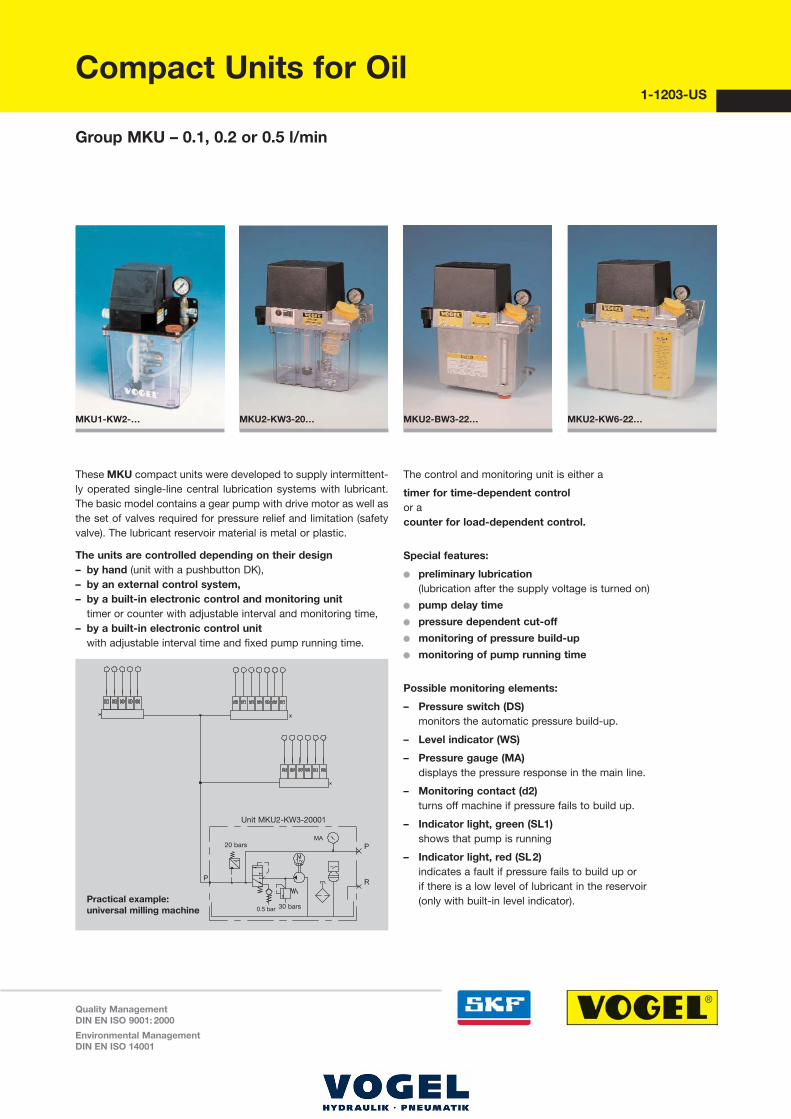
These MKU compact units were developed to supply intermittent�ly operated single�line central lubrication systems with lubricant.The basic model contains a gear pump with drive motor as well asthe set of valves required for pressure relief and limitation (safetyvalve). The lubricant reservoir material is metal or plastic.
The units are controlled depending on their design – by hand (unit with a pushbutton DK),– by an external control system,– by a built�in electronic control and monitoring unit
timer or counter with adjustable interval and monitoring time,– by a built�in electronic control unit
with adjustable interval time and fixed pump running time.
The control and monitoring unit is either a
timer for time�dependent controlor acounter for load�dependent control.
Special features:
�� preliminary lubrication (lubrication after the supply voltage is turned on)
�� pump delay time
�� pressure dependent cut�off
�� monitoring of pressure build�up
�� monitoring of pump running time
Possible monitoring elements:
– Pressure switch (DS)monitors the automatic pressure build�up.
– Level indicator (WS)
– Pressure gauge (MA)displays the pressure response in the main line.
– Monitoring contact (d2)turns off machine if pressure fails to build up.
– Indicator light, green (SL1)shows that pump is running
– Indicator light, red (SL2)indicates a fault if pressure fails to build up or if there is a low level of lubricant in the reservoir (only with built�in level indicator).
MKU2�BW3�22… MKU2�KW6�22… MKU1�KW2�… MKU2�KW3�20…
Group MKU – 0.1, 0.2 or 0.5 l/min
Compact Units for Oil1�1203�US
Quality ManagementDIN EN ISO 9001: 2000
Environmental ManagementDIN EN ISO 14001
Practical example: universal milling machine
Unit MKU2�KW3�20001
30 bars
20 bars

Im Folgenden finden Sie Informationen zu einem Teil unseres Leistungs-‐ und Serviceportfolios. Sollten Sie hierzu oder zu anderen Produkten Fragen haben, treten Sie jederzeit gern in Kontakt mit uns: Tel: 03573-‐ 14800 info@vogel-‐gruppe.de • Parker Store • Komponenten • 3D-‐Rohrbiege-‐Service • Wartung und Service • Hydraulik & Pneumatik • Aggregate-‐ und Anlagenbau • Mobiler Tag-‐ und Nacht vor-‐Ort-‐Service • Druckluft-‐Service • Schmiertechnik
Hauptsitz Senftenberg Laugkfeld 21, 01968 Senftenberg Tel: 03573 14 80-‐0 Bereitschaft: 0160 718 15 82 E-‐Mail: senftenberg@vogel-‐gruppe.de
Niederlassung Dresden Niedersedlitzer Str. 75 . 01257 Dresden Tel:0351 79 57 178 Bereitschaft: 0160 71 81 584 E-‐Mail: dresden@vogel-‐gruppe.de
Niederlassung Frankfurt/Oder Wildbahn 8, 15236 Frankfurt/Oder Tel: 0335 52 15 081 Bereitschaft: 0160 71 81 584 E-‐Mail: frankfurt@vogel-‐gruppe.de
Niederlassung Genshagen & Rohrbiegezentrum Seestr. 20, 14974 Genshagen Tel: 03378 87 90 67 Bereitschaft: 0171 22 65 930 E-‐Mail: genshagen@vogel-‐gruppe.de
Vertriebsgebiet Leipzig Tel.: +49 160 7181581 . E-‐Mail: leipzig@vogel-‐gruppe.de
Niederlassung Schöneiche August-‐Borsig-‐Ring 15, 15566 Schöneiche Tel: 030 64 93 581 Bereitschaft: 0160 71 81 590 E-‐Mail: schoeneiche@vogel-‐gruppe.de
Industrie-‐Hydraulik Vogel & Partner GmbH . Laugkfeld 21 . 01968 Senftenberg, Tel.: 03573 1480-‐0
info@vogel-‐gruppe.de . www.vogel-‐gruppe.de

Compact Units for Oil, Group MKU – 0.1, 0.2 or 0.5 l/min 1�1203�US 2
Delivery Reservoir Reservoir Control Componentsrate capacity material manual/ Hydraulic Wiring
Order No. [l/min] [l] *) external IG12 IG38�30 IZ38�30 DK DS WS MA layout diagram Drawing
MKU1�K2�10000 0.1 1.8 K external 1 1 1
MKU1�K2�10003 0.1 1.8 K external � 1 1 1
MKU1�KW2�10000 0.1 1.8 K external � 1 1 1
MKU1�KW2�10001 0.1 1.8 K external � � 1 1 1
MKU1�KW2�10003 0.1 1.8 K external � � 1 1 1
MKU1�KW2�10004 0.1 1.8 K external � � � 1 1 1
MKU2�K3�20000 0.2 3 K � � � 2 2 2
MKU2�K3�22005 0.2 3 K � � � 2 3 3
MKU5�K3�22005 0.5 3 K � � � � 2 3 3
MKU2�KW3�20001 0.2 3 K � � � � 2 2 2
MKU2�KW3�20003 0.2 3 K � � � � � 2 2 2
MKU2�KW3�20004 0.2 3 K � � � � 2 2 2
MKU2�KW3�20005 0.2 3 K � � � 2 2 2
MKU2�KW3�21003 0.2 3 K � � � � � 2 4 3
MKU2�KW3�21005 0.2 3 K � � � 2 4 3
MKU2�KW3�22001 0.2 3 K � � � � 2 3 3
MKU2�KW3�22003 0.2 3 K � � � � � 2 3 3
MKU2�KW3�22011 0.2 3 K � � � � 2 3 3
MKU2�KW3�22013 0.2 3 K � � � � � 2 3 3
MKU5�KW3�20001 0.5 3 K � � � � 2 2 2
MKU5�KW3�20003 0.5 3 K � � � � � 2 2 2
MKU5�KW3�22003 0.5 3 K � � � � � 2 3 3
MKU2�KW6�20001 0.2 6 K � � � � 2 2 4
MKU2�KW6�20003 0.2 6 K � � � � � 2 2 4
MKU2�KW6�22003 0.2 6 K � � � � � 2 3 5
MKU5�K6�22005 0.5 6 K � � � 2 3 5
MKU5�KW6�20001 0.5 6 K � � � � 2 2 4
MKU5�KW6�22001 0.5 6 K � � � � 2 3 5
MKU5�KW6�22003 0.5 6 K � � � � � 2 3 5
MKU2�BW3�20001 0.2 3 B � � � � 2 2 6
MKU2�BW3�20003 0.2 3 B � � � � � 2 2 6
MKU2�BW3�20005 0.2 3 B � � � 2 2 6
MKU2�BW3�21003 0.2 3 B � � � � � 2 4 7
MKU2�BW3�22001 0.2 3 B � � � � 2 3 7
MKU2�BW3�22003 0.2 3 B � � � � � 2 3 7
MKU2�BW3�22011 0.2 3 B � � � � 2 3 7
MKU2�BW3�22013 0.2 3 B � � � � � 2 3 7
MKU5�BW3�21003 0.5 3 B � � � � � 2 4 7
*) Reservoir material: K = plastic, B = metal
�� = components contained in the unit. DK = pushbutton / DS = pressure switch / WS = level indicator / MA = pressure gauge
Notice!
All products from Willy Vogel AG may be used only for their intendedpurpose and in accordance with the information contained in the ope�rating instructions belonging to the respective equipment.
In particular, we call your attention to the fact that hazardous mate�rials of any kind, especially the materials classified as hazardous by
EC Directive 67/548/EEC, Article 2, Par. 2, may only be filled intoVOGEL central lubrication systems and components and deliveredand/or distributed with the same after consultation with and writtenapproval from Willy Vogel AG.
See operating instruction 951�130�172.

Compact Units for Oil, Group MKU – 0.1, 0.2 or 0.5 l/min 1�1203�US 3
Technical data
Gear pump unit
Flow rate at 50 Hz . . . . . . . . . . . . . . 0.1; 0.2 or 0.5 l/minat 60 Hz . . . . . . . . . . . . . . 0.12; 0.24 or 0.6 l/min
in relation to a service viscosity of 140 mm2/s, at a back pressure of p = 5 bars
Operating pressure . . . . . . . . . . . . . 30 +1�2 bars
corresponds to actual value of built�in safety valve
Operating temperature. . . . . . . . . . . +10 to +40 °CMedium . . . . . . . . . . . . . . . . . . . . . . oil on a petroleum or
synthetic basiscompatible with . . . . . . . . . . . . . . . plastics, NBR elastomers,
copper, copper alloysService viscosity
MKU1 units: . . . . . . . . . . . . . . . . 20 � 750 mm2/sMKU2, MKU5 units: . . . . . . . . . . 20 � 1500 mm2/s
Reservoir capacity . . . . . . . . . . . . . . nominal 1.8, 3 or 6 lReservoir material . . . . . . . . . . . . . . plastic or metalType of enclosure. . . . . . . . . . . . . . . IP 54Frequency/voltage . . . . . . . . . . . . . . 50/60 Hz, 115 V AC or
50/60 Hz, 230 V ACplease indicate when ordering
Motor with built�in thermostatic switch
Mode of operation . . . . . . . . . . . . . . S3, 20% (1.25 to 25 min)duty cycle 1)
Power consumption approx. . . . . . 50 Hz: 115 W; 60 Hz: 140 WSpeed . . . . . . . . . . . . . . . . . . . . . . . 50 Hz: 2700 rpm;
60 Hz: 3300 rpm
Level indicator
Function. . . . . . . . . . . . . . . . . . . opens in event of low lubricant
Max. switching voltage . . . . . . . 42 V ACMax. switching current . . . . . . . 0.7 A(ohmic load)Max. contact rating . . . . . . . . . . 50 VA 2)
Pressure switch
Type of contacts . . . . . . . . . . . . closes when pressure builds upMax. switching voltage . . . . . . . 42 V ACMax. switching current . . . . . . . 2.5 A(ohmic load)Max. contact rating . . . . . . . . . . 30 VA 2)
Switching pressure . . . . . . . . . . 20 bars
1) The 20% duty cycle is the ratio of the pump running time to the subsequent idle timeExample:1 minute of pump running time requires at least 5 minutes of idle time.
The maximum permissible pump running time amounts to 3 minutes.That results in a necessary idle time of 15 minutes.
2) Take appropriate measures to protect contacts when switching inductive loads.
Dim
ensi
ons
in m
m
Drawing 1
1) Ports tapped for solderless tubeconnection for 8 mm diam. tube
2) Diameter for power lead 6 ... 8 mm
MKU1�K(W)2�10…
Compact Units for Oil, Group MKU – 0.1, 0.2 or 0.5 l/min 1�1203�US 4
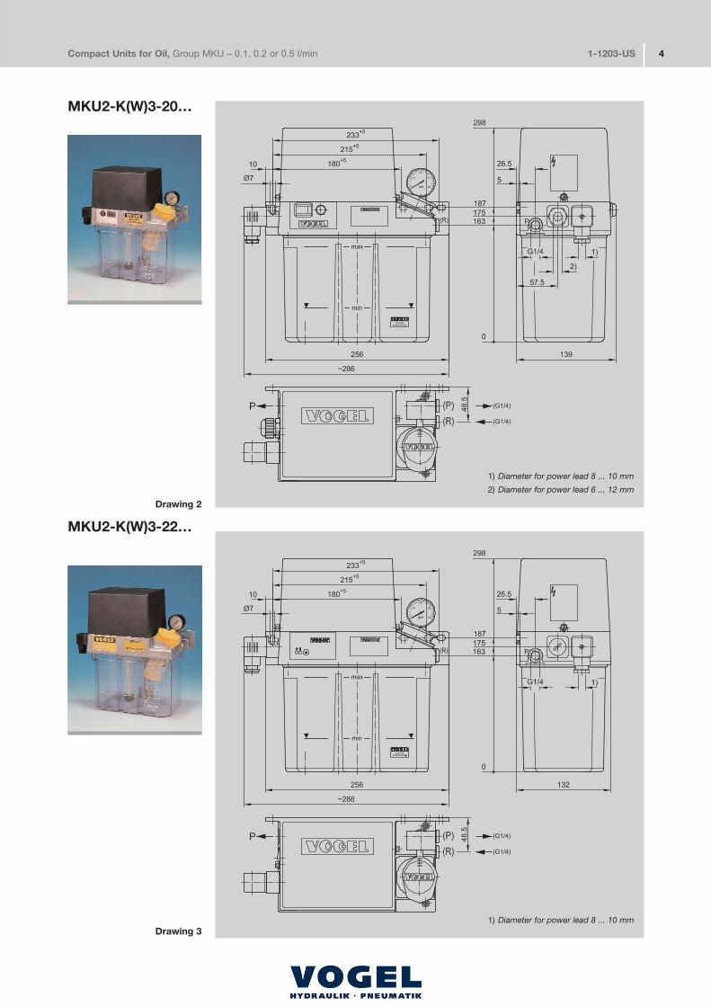
MKU2�K(W)3�20…
Drawing 2
1) Diameter for power lead 8 ... 10 mm
2) Diameter for power lead 6 ... 12 mm
Drawing 31) Diameter for power lead 8 ... 10 mm
MKU2�K(W)3�22…

Dim
ensi
ons
in m
mCompact Units for Oil, Group MKU – 0.1, 0.2 or 0.5 l/min 1�1203�US 5
Drawing 4
1) Diameter for power lead 8 ... 10 mm
2) Diameter for power lead 6 ... 12 mm
Drawing 51) Diameter for power lead 8 ... 10 mm
MKU2�KW6�20…
MKU2�KW6�22…
Compact Units for Oil, Group MKU – 0.1, 0.2 or 0.5 l/min 1�1203�US 6
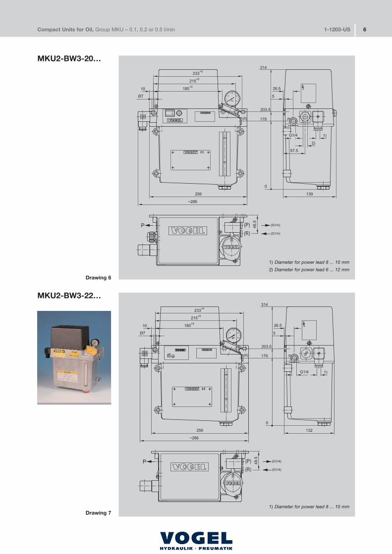
MKU2�BW3�20…
Drawing 6
1) Diameter for power lead 8 ... 10 mm
2) Diameter for power lead 6 ... 12 mm
Drawing 71) Diameter for power lead 8 ... 10 mm
MKU2�BW3�22…
Dim
ensi
ons
in m
mCompact Units for Oil, Group MKU – 0.1, 0.2 or 0.5 l/min 1�1203�US 7
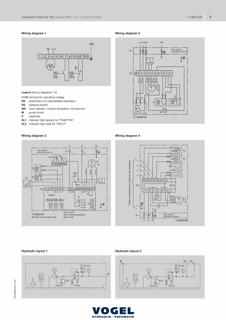
Hydraulic layout 1 Hydraulic layout 2
Wiring diagram 1
Wiring diagram 4Wiring diagram 3
Legend (wiring diagrams 1�4)
L1/N terminal for operating voltageDK pushbutton for intermediate lubricationDS pressure switchWS level indicator, contact illustration: full reservoirM pump motorC capacitorSL1 indicator light (green) for “PUMP ON”SL2 indicator light (red) for “FAULT”
Wiring diagram 2

Functions
– IG38�30�I: timer mode (time�dependent)
– IZ38�30�I: counter mode (load�dependent)
– Preliminary lubrication (lubrication after the supply voltage is switched on)
– Pump delay time
– Monitoring of pressure build�up
– Monitoring of pump runtime limitation
– Monitoring of lubricant level with wire�break detection(level indicator opens if lubricant level is critical)
Technical data
Interval duration preselectable in 12 stages:IG38�30�I (min) . . . . . . . . . . . . . . . . . 1; 2; 4; 8; 16; 32; 64; 128;
IZ38�30�I (pulses) 256; 512; 1024; 2048
Pump delay time, nonadjustable . . . . . . . . . . . . . . . . . . . . . . . 15 s
Pump runtime limitation, nonadjustable . . . . . . . . . . . . . . . . . 60 s
Rated voltage . . . . . . . . . . . . . . . . . . . . . . . . . . 115 or 230 V AC
Rated frequency . . . . . . . . . . . . . . . . . . . . . . . . . . . . . . . 50/60 Hz
Design . . . . . . . . . . . . . . . . . . . . . . . . . . . . . . . . board�mounted
Compact Units for Oil, Group MKU – 0.1, 0.2 or 0.5 l/min 1�1203�US 8
Sub
ject
to
chan
ge w
ithou
t no
tice!
0000
03/
2005
Willy Vogel AGMotzener Strasse 35/3712277 Berlin, GermanyP.O.Box 970444 ·12704 Berlin
Tel. +49 (0) 30 �7 20 02�0Fax +49 (0) 30 �7 20 02�111info@vogel�berlin.dewww.vogelag.com
Willy Vogel AG2. Industriestrasse 468766 HockenheimGermany
Tel. +49 (0) 62 05 � 27�0Fax +49 (0) 62 05 � 27�132info@vogel�berlin.dewww.vogelag.com
Vogel France SASRue Robert Amy, B.P. 7013049404 Saumur cedexFrance
Tel. +33 (0) 241 404 200Fax +33 (0) 241 404 [email protected]
The compact units with 3� or 6�liter reservoirs may be equipped with an electronic control unit for intermittently operated single�linecentral lubrication systems. Optionally with
�� IG38�30�I for time�dependent control�� IZ38�30�I for load�dependent control�� IG12 for time�dependent control (without monitoring functions)
The units conform to the following directives: Electromagnetic compatibility 89/336/EWG; 91/31/EWGLow voltage directive 73/23/EWG; 93/68/EWG
IG38�30�I control and monitoring unit with pre�lubrication, time�dependent or IZ38�30�I, load�dependent
Functions
– Timer with adjustable interval time and constant lubrication time
– Operation always begins with an interval when the supply voltage is switched on
– Intermediate lubrication via pushbutton DK is possible at any time during an interval
Technical data
Rated voltage . . . . . . . . . . . . . . . . . . . . . . . . . . 115 or 230 V AC
Rated frequency . . . . . . . . . . . . . . . . . . . . . . . . . . . . . . 50/60 Hz
Interval time (min)preselectable in 10 stages: 1.5; 3; 6; 12; 24; 48; 96; 192; 384; 768As�delivered setting . . . . . . . . . . . . interval time set for 1.5 minContact time, fixed . . . . . . . . . . . . . . . . . . . . . . . . . . . . . . . 20 sDesign . . . . . . . . . . . . . . . . . . . . . . . . . . . . . . . . plastic housingTerminal bloc for level indicator (WS) and pressure switch (DS)
IG12 control unit without pre�lubrication, time�dependent, without monitoring functions
Leaflet information
1�0016�US Compact units for grease1�1700�1�US Control units
{