compact & lightweight stepping motor and driver package pmc … · 2018-05-15 · 4 operation...
TRANSCRIPT
1
HP-7420-4
Table of ContentsSafety precautions ................................. Page 2Product verification ................................ Page 5Names and function of driver parts ....... Page 7Installation ............................................. Page 9Driver function swithces ........................ Page 15Input/output signals ............................... Page 16Connections ........................................... Page 22Motor current adjustment ...................... Page 24Troubleshooting ..................................... Page 27Specifications ........................................ Page 30Installing and wiring in compliance with EMC directive ....... Page 33
Compact & Lightweight Stepping Motor and Driver Package
PMC SeriesStandard TypeMG Geared TypeHarmonic Geared Type
OPERATING MANUAL
Thank you for purchasing an Oriental Motor product.This Operating Manual describes product handling procedures and safety precautions.• Please read it thoroughly to ensure safe operation.• Always keep the manual where it is readily available.

2
Safety precautionsOnly qualified personnel should work with the product.Use the product correctly after thoroughly reading the section “Safety precautions.”The precautions described below are intended to prevent danger or injury to the user andother personnel through safe, correct use of the product. Use the product only aftercarefully reading and fully understanding these instructions.
WarningHandling the product without observing the instructions that accompany a “Warning”symbol may result in serious injury or death.
CautionHandling the product without observing the instructions that accompany a “Caution”symbol may result in injury or property damage.
NoteThe items under this heading contain important handling instructions that the user shouldobserve to ensure safe use of the product.
WarningGeneral• Do not use the product in explosive or corrosive environments, in the presence of
flammable gases, locations subjected to splashing water, or near combustibles. Doingso may result in fire or injury.
• Assign qualified personnel the task of installing, wiring, operating/controlling, inspectingand troubleshooting the product. Failure to do so may result in fire or injury.
Installation• Install the motor and driver in their enclosures in order to prevent injury.
Connection• Keep the driver’s input-power voltage within the specified range to avoid fire.• The driver power supply to be used should be a DC power supply where the primary
and secondary sides are provided with reinforced insulation. Otherwise, an electricshock may occur.
• Connect the cables securely according to the wiring diagram in order to prevent fire.• Do not forcibly bend, pull or pinch the cable. Doing so may fire.

3
Operation• Turn off the driver power in the event of a power failure, or the motor may suddenly start
when the power is restored and may cause injury or damage to equipment.• When you want to use the motor in a vertical application, take position holding
measures. When the power is turned off, the motor will lose the holding brake force.The movable part will drop and possibly cause injury to personal and damage to theequipment.
• Do not turn the output current off input to “ON” while the motor is operating. The motorwill stop and lose its holding ability, which may result in injury or damage to equipment.
Repair, disassembly and modification• Do not disassemble or modify the motor or driver. This may cause injury. Refer all such
internal inspections and repairs to the branch or sales office from which you purchasedthe product.
CautionGeneral• Do not use the motor and driver beyond their specifications, or injury or damage to
equipment may result.• Do not touch the motor or driver during operation or immediately after stopping. The
surfaces are hot and may cause a burn.
Transportation• Do not hold the motor output shaft or motor cable. This may cause injury.
Installation• Keep the area around the motor and driver free of combustible materials in order to
prevent fire or a burn.• To prevent the risk of damage to equipment, leave nothing around the motor and driver
that would obstruct ventilation.• The motor and driver should be firmly secured on the metallic plate in order to prevent
personal injury or equipment damage.• Provide a cover over the rotating parts (output shaft) of the motor to prevent injury.

4
Operation• Use a motor and driver only in the specified combination. An incorrect combination may
cause a fire.• To avoid injury, remain alert during operation so that the motor can be stopped
immediately in an emergency.• Before supplying power to the driver, turn all control inputs to the driver to “OFF.”
Otherwise, the motor may start suddenly and cause injury or damage to equipment.• Make sure that the output power off input of the driver is turned on if you want to move
the motor shaft directly (e.g. for manual positioning). This caution is to preventpersonal injury.
• When an abnormality is noted, stop the operation immediately, or fire or injury mayoccur.
Disposal• When disposing of the motor or driver, treat them as ordinary industrial waste.
NoteBefore using the product, read the content of the label carefully.The content and stick position of the label are as follows.
Please pay attention to the following to the product work in the best condition.
Do not take the product out of the protective bag until ready to use it.Do not touch parts and contacts to avoid electrostatic damage.Do not expose the product to vibration or shock.Keep the product away from dusty and humid condition.
MNX7227
Driver
Protective bagATTENTION

5
Product verificationEquipment checklist• Motor ........................................................................ 1• Driver ....................................................................... 1• M2.5 Cross recessed head machine screws
with washer for mounting the motor(for only MG geared type) ........................................ 4
• Connector for signals6-173977-4 (AMP), 6-173977-8 (AMP) .................... 2
• Connector for power supply6-173977-3 (AMP) ................................................... 1
• Connector for motor connection6-173977-5 (AMP) ................................................... 1
• Operating manual .................................................... 1
NoteDo not take the product out of the protective bag until ready to use it. Otherwise, the drivermay be damage.
Model numbers and motor/driver combinationsThe PMC series is a combined package which includes a stepping motor and driver.This operating manual is designated for the following products.
Package model number
PMC33A3
PMC33B3
PMC35A3
PMC35B3
PMC33A1-MG ∗ 1
PMC33B1-MG ∗ 1
PMC33A1-HG ∗ 2
PMC33B1-HG ∗ 2
Driver model number
PMD03CA
Motor model number
PMM33A2
PMM33B2
PMM35A2
PMM35B2
PMM33A-MG ∗ 1
PMM33B-MG ∗ 1
PMM33A-HG ∗ 2
PMM33B-HG ∗ 2
The box ( ∗ 1) represents the desired gear ratio (3.6, 7.2, 10, 20, 30, 50).The box ( ∗ 2) represents the desired gear ratio (50, 100).
NoteThe motor and the driver are precision equipment and should not be dropped or subject toany physical shocks.

6
Interpreting the model number
Reference number
Shaft typeA:Single shaftB:Double shaft
Motor case length3:31mm (1.22in.)5:50.5mm (1.99in.)
Motor frame size 3:28mm (1.1in.) sq.
Compact & lightweight stepping motor and driver packagePMC series
P M C 3 3 A 3P M C 3 3 A 3P M C 3 3 A 3P M C 3 3 A 3P M C 3 3 A 3
P M C 3 3 A 1 - M G 3.6P M C 3 3 A 1 - M G 3.6P M C 3 3 A 1 - M G 3.6P M C 3 3 A 1 - M G 3.6P M C 3 3 A 1 - M G 3.6Gear ratio
MG geared type3.6: 3.6:1 20 : 20:17.2: 7.2:1 30 : 30:110 : 10:1 50 : 50:1
Harmonic geared type50 : 50:1 100 : 100:1
Shaft typeA:Single shaftB:Double shaft
Motor case length
Motor frame size 3:28mm (1.1in.) sq.
Compact & lightweight stepping motor and driver packagePMC series
Geared typeMG : MG gearHG : Harmonic gear
Reference number

7
Names and functions of driver partsIllustration shows the view from the connector side.
LED indications
GND
POWER
RUN
STOP
F H
2P 1P
+
+
+
+
+
+
+
ORGRED
TIM
BLU
GRNBLK
24 / 36V
NC
SIG
NA
L 1
SIG
NA
L 2
MO
TO
RP
OW
ER
11
1C
N1
CN
4C
N3
1C
N2
C.UP
F/H
C.OFF
CCW/D.
CW/P.
VEXTA STEPPING DRIVER
⑦
①
⑨
⑧
②
③
④⑤
⑥
Potentiometers and switches
Indication
② RUN
③STOP
④ F/H
⑤ 2P/1P
Run potentiometer
Stop potentiometer
Step angle switch
Pulse input modeswitch
0.35A/phase
0.175A/phase
F
1P
Name Factorysetting
Current adjustment potentiometer usedwhen motor is running.Motor standstill current adjustmentpotentiometer used when current hasbeen cut back by the automatic currentcutback function when there is no pulseinput (motor standstill).The motor step angle can be set to fullstep or half step with this switch.The pulse signal input mode can be setto 1-pulse input mode or 2-pulse inputmode this switch.
Function
Page25
Page25, 26
Page15
Page15
Pagereference
Indication
① POWER Power input LED Green
LED name Color
Lights when the power is input.
Conditions when LED ON

8
TerminalsIndication Terminal name FunctionPin
No.Page
reference
Page16, 17
Page16, 17
Page18, 19
Page19
Page20
Page21
Page22, 23Page22, 23Page22, 23Page22, 23Page22, 23
Page22
The pulse mode signal is input to thisterminal. The direction of the motor’srotation is determined by the followingrotation direction input terminal.(When in 2-pulse input mode the CWdirection command pulse signal is inputto this terminal.)The rotation direction signal is input tothis terminal. When a signal is input to the terminal the motor output shaft willrotate the counterclockwise direction.(When in 2-pulse input mode the CCWdirection command pulse signal is inputto this terminal.)The all windings off signal is input to thisterminal.When a signal is input to the terminal thedriver will cut the power supply to themotor.The motor torque will then be reduced tozero and the motor shaft can be rotatedfreely for adjustment.This function is used when manualpositioning etc. is required.The motor step angle is input to thisterminal.The automatic current cutback releasesignal is input to this terminal.Signal for deactivating the automaticcurrent cutback function, which cuts backthe output current to the motor when it isstandstill.
Signal indicating that the motor excitationsequence is at step “0”.
Connect this terminal to the blue lead wire.Connect this terminal to the red lead wire.Connect this terminal to the orange lead wire.Connect this terminal to the green lead wire.Connect this terminal to the black lead wire.
Connect this terminal to a “+” side ofDC24V or DC36V and GND.
No connection.
⑥ SIGNAL 16-173977-8(AMP)∗ 1The selection ofthe pulse signalinput mode canbe set with thepulse inputmode switch.∗ 2In this table, therotation directionshows that ofmotor outputshaft.For harmonicgeared type andgear ratio 10:1 ofMG geared type,the motor rotationdirection isopposite to theoutput shaftrotation direction.
⑦ SIGNAL 26-173977-4(AMP)
⑧ MOTOR6-173977-5(AMP)
⑨ POWER6-173977-3(AMP)
1
2
3
4
5
6
78
1
2
3
4
12345
1
2
3
(Pulse/CW PulseSignal InputTerminal)
(Pulse/CW PulseSignal InputTerminal)
(Rotation Direction/CCW Pulse SignalInput Terminal)
(Rotation Direction/CCW Pulse SignalInput Terminal)
(All Windings OffSignal InputTerminal)
(All Windings OffSignal InputTerminal)
Motor Connection Terminal
24/36V
GND
NC
(Step Angle Signal Input Terminal)(Step Angle Signal Input Terminal)
(Automatic CurrentCutback ReleaseSignal Input Terminal)(Automatic CurrentCutback ReleaseSignal Input Terminal)
(Excitation TimingSignal Output Terminal)(Excitation TimingSignal Output Terminal)
(Power SupplyConnection Terminal)(Power SupplyConnection Terminal)
CW/P.+
CW/P.-
CCW/D.+
CCW/D.-
C.OFF+
C.OFF-
F/H+F/H-
C.UP+
C.UP-
TIM+
TIM-
9
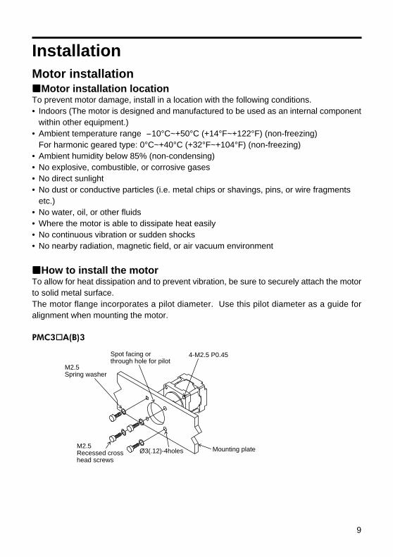
PMC3 A(B)3
M2.5Spring washer
M2.5Recessed cross head screws
Mounting plateØ3(.12)-4holes
Spot facing or through hole for pilot
4-M2.5 P0.45
InstallationMotor installation
Motor installation locationTo prevent motor damage, install in a location with the following conditions.• Indoors (The motor is designed and manufactured to be used as an internal component
within other equipment.)• Ambient temperature range -10°C~+50°C (+14°F~+122°F) (non-freezing)
For harmonic geared type: 0°C~+40°C (+32°F~+104°F) (non-freezing)• Ambient humidity below 85% (non-condensing)• No explosive, combustible, or corrosive gases• No direct sunlight• No dust or conductive particles (i.e. metal chips or shavings, pins, or wire fragments
etc.)• No water, oil, or other fluids• Where the motor is able to dissipate heat easily• No continuous vibration or sudden shocks• No nearby radiation, magnetic field, or air vacuum environment
How to install the motorTo allow for heat dissipation and to prevent vibration, be sure to securely attach the motorto solid metal surface.The motor flange incorporates a pilot diameter. Use this pilot diameter as a guide foralignment when mounting the motor.

10
PMC33A(B)1-MG
PMC33A(B)1-HG
M3Spring washer
M3Hexagonal socket screws
Mounting plate
4-M3 P0.5
Ø3.5(.14)-4holes
Spot facing or through hole for pilot
The following hardware (not supplied) is needed to mount the motor.For the installation of the MG geared type, use the supplied screws.
Select screws with a length appropriate for the thickness of the mounting plate.(Refer to the below table.)
M2.5Cross recessed head machine screws withwasher (attached)
Mounting plateØ3(.12)-4holes
Spot facing or through hole for pilot
4-M2.5 P0.45
PMC3 A(B)3
PMC33A(B)1-HG
・M2.5 Recessed cross head screws : 4・M2.5 Spring washers : 4・M3 Hexagonal socket screws : 4・M3 Spring washers : 4
Length of the screws [Unit: mm (inch)]
thickness of the mounting plate +2.5 (0.1)
thickness of the mounting plate +3.5 (0.14)thickness of the mounting plate +5 (0.2)
ModelPMC33A(B)3PMC35A(B)3
PMC33A(B)1-MG
PMC33A(B)1-HG

11
PMC33A(B)1-MG
PMC33A(B)1-HG
Spot facing or through hole for pilot23
±0.
2(.9±
.008
)
23±0.2(.9±.008)
Ø3(.12)-4holes
Ø5.5(.22)min.Shaft hole
X
X’
R0.3(.01)max.
2(.08)min.
X-X’
1.5(.059)min.Ø22+0.033 0 .87+.0013
0( )
Ø22
+0.0
33 0
.87
+.00
13 0
()
X
X-X’
Ø11.5(.45)Spot facing or through hole for pilot23
±0.
2(.9±
.008
)6±
0.2(
.2±
.008
)
23±0.2(.9±.008)
Ø3(.12)-4holes
Ø5.5(.22)min.Shaft hole
X’
R0.5(.02)max.
Ø11
.5(.
45)
2(.08)min.
2(.08)min.
Spot facing or through hole for pilot23
±0.
2(.9±
.008
)
23±0.2(.9±.008)
Ø3.5(.14)-4holes
Ø8.5(.33)min.Shaft hole
X
X’
R0.3(.01)max.
5(.2)min.
X-X’
2(.08)min.Ø22+0.033 0 .87+.0013
0( )
Ø22
+0.0
33 0
.87
+.00
13 0
()
Motor mounting plate dimensions
[unit: mm (inch)]
PMC3 A(B)3

12
Permissible thrust load [Unit: N (lb.)]
The box ( ∗ 1) represents the desired gear ratio (3.6, 7.2, 10, 20, 30, 50).The box ( ∗ 2) represents the desired gear ratio (50, 100).
Connecting the motor to the drive mechanism (Load)
Proper alignment is necessary whenconnecting the drive mechanism (load) tothe motor shaft. Use a flexible coupling.
Distance from the endof the shaft [mm (inch)]
PMC3 A(B)3
PMC33A(B)1-MG ∗ 1
PMC33A(B)1-HG ∗ 2
0
25 (5.51)9.2 (2.02)
140 (30.8)
15 (0.59)
21.9 (4.82)240 (52.8)
5 (0.2)
34 (7.49)
11.4 (2.51)
160 (35.2)
10 (0.39)
52 (11.4)
15 (3.3)200 (44.1)
Note• Inadequate alignment may reduce the life span of the motor bearings or damage the
motor shaft.• Exceeding the permissible overhung load or permissible thrust load will damage or shorten
the life span of the bearings and motor shaft.Do not exceed the permissible overhung load and thrust load as indicated in thefollowing chart.
• For geared motor, do not separate the motor and the gearhead.
Permissible overhung load [Unit: N (lb.)]
Ball screw Coupling
Stepping motor
PMC33A(B)3
PMC35A(B)3
PMC33A(B)1-MG ∗ 1
PMC33A(B)1-HG ∗ 2
1 (0.22)1.7 (0.374)10 (2.2)100 (22)

13
Driver installationDriver installation location
To prevent driver damage, install in a location with the following conditions.• Indoors (The driver is designed and manufactured to be used as an internal component
within other equipment.)Ambient temperature range 0°C~+40°C (+32°F~+104°F) (non-freezing).Install a forced-air cooling fan if ambient temperatures exceed +40°C (+104°F).
• Ambient humidity below 85%(non-condensing)• No explosive, combustible, on corrosive gases• No direct sunlight• No dust or conductive particles (i.e. metal chips or shavings, pins, or wire fragments
etc.)• No water, oil, or other fluids• Where the driver is able to dissipate heat easily• No continuous vibration or sudden shocks• No nearby radiation, magnetic field, or air vacuum environment• If the driver is installed in a switch box or other enclosed area, and near a heat source,
be sure to establish ventilation holes. The heat generated by the driver will cause theambient temperature to rise which could consequently damage the driver.
• If the driver is installed near a source of vibration, and this vibration is transmitted to thedriver, attach a shock absorber to prevent driver damage.
• If the driver is installed near a source of noise interference (i.e. high frequency weldingmachine, electromagnetic switch, etc.) install a noise filter, or connect it to a separatepower source to reduce the effect of the interference, otherwise the motor may notoperate correctly.
• Leave a space of at least 25mm (1in.). If using more than one driver, leave a space of atleast 20mm (0.8in.) between each driver. Driver heat generation will cause the ambienttemperature to rise, and if the permissible ambient operating temperature is exceeded,driver damage may result.
How to install the driverThe driver is designed to cool naturally by convection.Secure the driver to a metal plate made of steel, aluminium or other material having goodthermal conductivity.
The following hardware (not supplied) is needed to mount the driver.• M3 Screws : 4• M3 Spring washers : 4• Insulation type spacers : 4• M3 Nuts : 4

14
Driver mounting plate dimensions
Horizontal mounting Vertical mounting
Connector
Securing the driver1. Insert spring washers and M3 screws from the surface of the connector side of the
circuit board.2. Insert the spacer between the driver and the mounting plate, and secure by using M3
nuts.• Spacer size: Ø9mm (0.35in.) max. 6mm (0.24in.) min. long• Screw tightening torque: 0.5N·m (71oz-in)
[Unit: mm (inch)]
72(2.83)
66±0.3(2.6±.01)
50±
0.3(
1.97±
.01)
3(.1
2)
3(.12) Ø3.2(.13)-4holes
56(2
.2) 6(.24)min.
M3 Screw
M3 Spring washer
Driver
M3 nut
Chassis
Insulationtype spacer
15
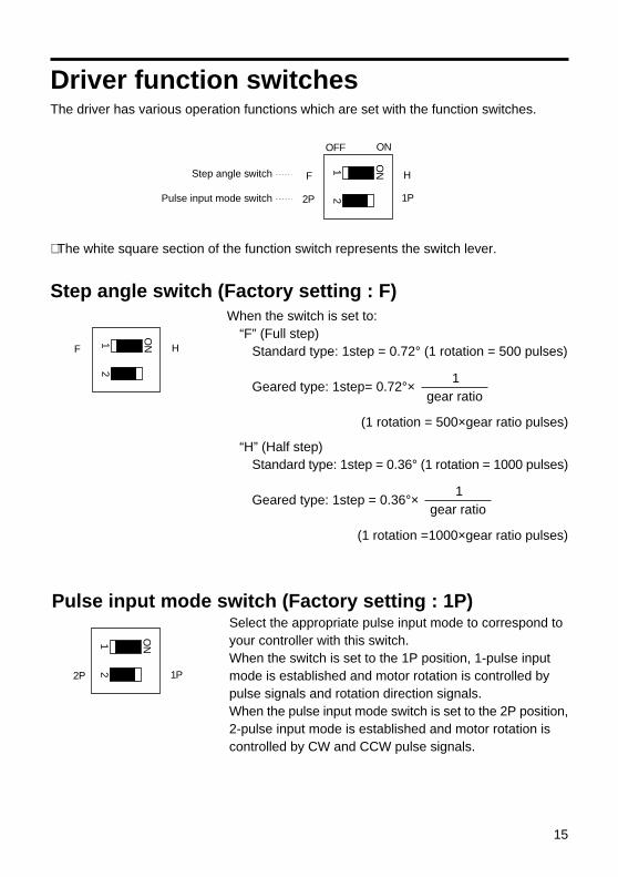
Pulse input mode switch (Factory setting : 1P)Select the appropriate pulse input mode to correspond toyour controller with this switch.When the switch is set to the 1P position, 1-pulse inputmode is established and motor rotation is controlled bypulse signals and rotation direction signals.When the pulse input mode switch is set to the 2P position,2-pulse input mode is established and motor rotation iscontrolled by CW and CCW pulse signals.
When the switch is set to:“F” (Full step)
Standard type: 1step = 0.72° (1 rotation = 500 pulses)
Geared type: 1step= 0.72°×
(1 rotation = 500×gear ratio pulses)
Driver function switchesThe driver has various operation functions which are set with the function switches.
F H
2P 1P
OFF ON
ON1
2
Step angle switch
Pulse input mode switch
∗ The white square section of the function switch represents the switch lever.
Step angle switch (Factory setting : F)
2P 1P
ON1
2
F H
ON1
2
“H” (Half step)Standard type: 1step = 0.36° (1 rotation = 1000 pulses)
Geared type: 1step = 0.36°×
(1 rotation =1000×gear ratio pulses)
1gear ratio
1gear ratio
16
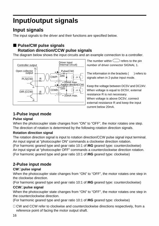
1-Pulse input modePulse signalWhen the photocoupler state changes from “ON” to “OFF”, the motor rotates one step.The direction of rotation is determined by the following rotation direction signals.Rotation direction signalThe rotation direction signal is input to rotation direction/CCW pulse signal input terminal.An input signal at “photocoupler ON” commands a clockwise direction rotation.(For harmonic geared type and gear ratio 10:1 of MG geared type: counterclockwise)An input signal at “photocoupler OFF” commands a counterclockwise direction rotation.(For harmonic geared type and gear ratio 10:1 of MG geared type: clockwise)
2-Pulse input modeCW∗ pulse signalWhen the photocoupler state changes from “ON” to “OFF”, the motor rotates one step inthe clockwise direction.(For harmonic geared type and gear ratio 10:1 of MG geared type: counterclockwise)CCW∗ pulse signalWhen the photocoupler state changes from “ON” to “OFF”, the motor rotates one step inthe counterclockwise direction.(For harmonic geared type and gear ratio 10:1 of MG geared type: clockwise)
∗ CW and CCW refer to clockwise and counterclockwise directions respectively, from areference point of facing the motor output shaft.
V0
R
R
Pulse(CW)
Rotation direction(CCW)
220Ω
220Ω
20mA max.
20mA max.
Controller outputDriver input (Internal circuit)
Open collectoroutput
CW/P.
CCW/D.
PLS(CW)
DIR.(CCW)
+
+-
-
2
1
3
4
The number within refers to the pinnumber of driver connector SIGNAL 1.
The information in the brackets ( ) refers tosignals when in 2-pulse input mode.
Keep the voltage between DC5V and DC24V.When voltage is equal to DC5V, externalresistance R is not necessary.When voltage is above DC5V, connectexternal resistance R and keep the inputcurrent below 20mA.
Input/output signalsInput signalsThe input signals to the driver and their functions are specified below.
Pulse/CW pulse signalsRotation direction/CCW pulse signals
The diagram below shows the input circuits and an example connection to a controller.

17
Pulse signal
5µsmin.
2µsmax.
90%10%
Rotation direction signal
10µsmin.
5µsmin.
2µsmax.
10µsmin.
Photocoupler ON
Photocoupler ON
Photocoupler OFF
Photocoupler OFF
2-Pulse input mode
Relation to the pulse input mode switchWhen the switch is set to the 1P position, motor rotation is controlled by pulse signals androtation direction signals.When the switch is set to the 2P position, motor rotation is controlled by CW pulse signalsand CCW pulse signals.
Pulse waveform characteristics
1-Pulse input mode
Photocoupler ON
CW pulse signal
5µsmin.
5µsmin.
2µsmax.
90%10%
CCW pulse signal10µsmin.
2µsmax.
Photocoupler ON
Photocoupler OFF
Photocoupler OFF
• The shaded area indicates when the photocoupler diode is ON. The motor moves whenthe photocoupler states changes from ON to OFF as indicated by the arrow.
• The pulse voltage is 4~5V in the “photocoupler ON” state, and 0~0.5V in the“photocoupler OFF” state.
• Input pulse signals should have a pulse width over 5µs, pulse rise/fall below 2µs, anda pulse duty below 50%.
• Keep the pulse signal in the “photocoupler OFF” state when no pulse is being input.• The minimum interval time when changing rotation directions is 10µs.• In 1-pulse input mode, leave the pulse signal at rest “photocoupler OFF” when
changing rotation directions.• In 2-pulse input mode, do not input CW and CCW pulse signals at the same time.
Inputting a pulse signal while the other pulse signal is already in the “photocouplerON” state will result in erratic motor rotation.

18
All windings off signalThe diagram below shows the input circuit and an example connection to a controller.
The number within refers to the pinnumber of driver connector SIGNAL 1.
Keep the voltage between DC5V and DC24V.When voltage is equal to DC5V, externalresistance R is not necessary.When voltage is above DC5V, connectexternal resistance R, and keep the inputcurrent below 20mA.
R
+ 220Ω
20mA max.
Controller output
Open collectoroutput
-
Driver input (Internal circuit)
C.OFFC.OFF
5
6
V0
When the all windings off signal is in the “photocoupler ON” state, the current to the motoris cut off and motor torque is reduced to zero. The motor output shaft can then be rotatedfreely by hand.When the all windings off signal is in the “photocoupler OFF” state, the motor holdingtorque is proportional to the current set by the current adjustment rotary switches. Duringmotor operation be sure to keep the signal in the “photocoupler OFF” state.This signal is used when moving the motor by external force or manual home positioningetc. is desired. If this function is not needed, it is not necessary to connect this terminal.Switching the all windings off signal from “photocoupler ON” to “photocoupler OFF” doesnot alter the excitation sequence.When the motor shaft is manually adjusted with the all windings off signal input, the shaftwill shift up to ±3.6°(geared type: ±3.6°/gear ratio) from the position set after the all windings off signal isreleased.

19
Manual detection of the home positionInput the all windings off signal, set the motor to the desired position, then release the allwindings off signal.
The number within refers to the pinnumber of driver connector SIGNAL 1.
Keep the voltage between DC5V and DC24V.When voltage is equal to DC5V, externalresistance R is not necessary.When voltage is above DC5V, connectexternal resistance R, and keep the inputcurrent below 20mA.
Half StepStandard type:When the step angle signal is in the“photocoupler ON” state, it is set to half-stepmode (0.36°/step, 1 rotation 1000 pulses)Geared type:When the step angle signal is in the“photocoupler ON” state, it is set to half-stepmode(0.36°× / step,
1 rotation 1000×gear ratio pulses)
Full StepStandard type:When the step angle signal is in the“photocoupler OFF” state, it is set to full-step mode (0.72°/step, 1 rotation 500pulses)Geared type:When the step angle signal is in the“photocoupler OFF” state, it is set to full-step mode(0.72°× / step,
1 rotation 500×gear ratio pulses)NoteWhen the step angle signal is used, the switch must be set to the F position.
1gear ratio
1gear ratio
R
+ 220Ω
20mA max.
Controller output
Open collectoroutput
-
Driver input (Internal circuit)
F / HF / H
7
8
V0
All windings off signal input
Home positionset
All windings off signal input
All windings off signal release
Photocoupler ONPhotocoupler OFF
OFF OFFON
NoteFor geared type, do not do manual detection of the home position. It may cause damagethe gearhead and may cause the following problems.• The motor makes a strange noise.• The motor does not rotates correctly.
Step angle signalThe diagram below shows the input circuit and an example connection to a controller.

20
Automatic current cutback release signalThe diagram below shows the input circuit and an example connection to a controller.
The number within refers to the pinnumber of driver connector SIGNAL 2.
Keep the voltage between DC5V and DC24V.When voltage is equal to DC5V, externalresistance R is not necessary.When voltage is above DC5V, connectexternal resistance R, and keep the inputcurrent below 20mA.
R
+ 220Ω
20mA max.
Controller output
Open collectoroutput
-
Driver input (Internal circuit)
C.UPC.UP
1
2
V0
• When the automatic current cutback release signal is in the “photocoupler OFF” state,the automatic current cutback function is activated; 0.1s. after the pulse is stopped themotor output current is automatically cut back, reducing motor and driver heat.(The factory setting for the current cutback is 50%. In order to change this, refer to theinstructions for adjusting the current at motor standstill on pages 25, 26)
• When the maximum holding torque is needed, input “photocoupler ON” signal. Theautomatic current cutback function is deactivated.
• When the automatic current cutback release signal is in the “photocoupler ON” state,the automatic current cutback function is deactivated.
• Because the motor’s holding power is proportional to the motor output current, the motor’sholding power is reduced when the current is cut back. (The motor has holding powerproportional to the current at motor standstill, which is set with the STOP potentiometer.Refer to page 24.)
NoteGenerally, automatic current cutback release signal should be set to “photocoupler OFF”to suppress heat generation in the motor and driver.

21
The excitation timing signal is output to indicate when the motor excitation (current flowingthrough the winding) is in the initial stage (step “0” at power up ).The excitation timing signal can be used to increase the accuracy of home positiondetection by setting mechanical home position of your equipment (photo-sensor etc.) tocoincide with the excitation sequence initial stage (step “0”).When connected as shown in the example connection, the signal will be “photocouplerON” at step “0”.
The excitation timing signal is output simultaneously with a pulse input each time theexcitation sequence returns to step “0”.The excitation sequence will complete one cycle for every 7.2° rotation of the motor outputshaft.When the power is turned ON, the excitation sequence is reset to step “0”.
Relation to the step angle switchWhen the switch is set to the F position:
Full step: signal is output once every 10 pulses(Standard type: 0.72°/step, Geared type: 0.72°× / step)
When the switch is set to the H position:Half step: signal is output once every 20 pulses(Standard type: 0.36°/step, Geared type: 0.36°× / step)
Timing chart when in full step mode
Output signalsThe output signals from the driver and their functions are specified below.
Excitation timing signalThe diagram below shows the output circuit and an example connection to a controller.
The number within refers to the pinnumber of driver connector SIGNAL 2.
Keep the voltage between DC5V and DC24V.Keep the current below 10mA.If the current exceeds 10mA, connect externalresistance R.
1gear ratio
1gear ratio
Controller outputDriver input (Internal circuit)
V0
R
10mA max.
TIM
3
4
+
-
Pulse
Rotation direction
Excitation timing output
1 2 3 4 5 6 7 8 9 101112
1 2
Step 11 2 3 4 5 6 7 8 9 0 1 20 0

22
ConnectionsConnecting the motor, driver and power supply• For signal lines, use twisted pair wire of AWG28 (0.08mm2) or greater, and 1m (39.4in.)
or less in length.• For power lines and when extending the motor lead wires use wires of AWG26 (0.14mm2)
or greater.• Separate the signal lines from the power lines and motor lead wires by at least 30cm
(11.8in.). Do not band place the signal lines in the same duct as, or bind them togetherwith, power lines, as this makes it easier for noise to enter the signal line, which cancause operating errors.
• Use an open collector transistor (sink type) for the controller signal output.• If electrical noise generated by the motor lead wires or other equipment causes
operational errors, shield the signal lines with conductive tape or wire mesh etc. (notsupplied).
Pressure welding of the connectors• The suitable wire size of AWG28 (0.08mm2) to AWG26 (0.14mm2) with a sheathing
having an outside diameter of 0.85mm (0.03in.)~1.05mm (0.04in.).Use a wire rated at AWG26 (0.14mm2) for the power line.
• Use the tool specified by the connector manufacturer (AMP 911790-1) for pressurewelding of the terminals.
NoteWhen pulling and inserting the connector to the driver, hold the connector itself.Otherwise, the motor and the driver may be damaged.
Driver power supplyThe input power voltage should come from a DC24V or DC36V power supply which isreinforced insulation.
The input current of the power supply is 0.7A or less.Use a power supply which will supply sufficient input current.(The current value for input power is a maximum value when connecting the drivemechanism (load) to the motor shaft.)
NoteIf the current from the power supply is insufficient the motor torque will be reduced and thetransformer may be damaged. The following abnormalities may also occur.• Erratic motor rotation during high speeds• Delayed motor start-up and stopping

23
Example connectionsConnection to user’s controller
+
-
N.C (power supply which is reinforced insulation)
GND
+24 / 36V
R1
R1
R2
R0
V0(+5V~24V)
User’s controller
R1
R1
R1
GND
SIG
NA
L1S
IGN
AL2
MO
TO
RP
OW
ER
CW / P.+
+CCW / D.
+C.OFF
+F / H
+C.UP
+TIM
BLU
RED
ORG
GRN
BLK
+24 / 36V
GND
NC
Driver( )
②
③
④
①
②
③
①
②
③
④
⑤
⑥
⑦
⑧
②
③
①
④
①
⑤
Pulse/CW pulse signal input
Rotation direction/CCW pulse signal input
DC24V or DC36V Power supply
Stepping motor
All windings off signal input
Step angle signal input
Automatic current cutback release signal input
Excitation timing Signal output
Blue
Red
Orange
Green
Black
DC POWERSUPPLY
+-
+24V±10%
GND
Note: For operations involving sudden deceleration or the driving of large inertial loads, connect a capacitor of 1000µF or more to suppress the motor’s regenerative voltage.
Input signal connectionsKeep the voltage between DC5V and DC24V.When voltage is equal to DC5V, external resistance R1 is not necessary.When voltage is above DC5V, connect external resistance R1 and keep the inputcurrent below 20mA.
Output signal connectionsKeep the voltage between DC5V and DC24V.Keep the current below 10mA.If the current exceeds 10mA, connect external resistance R2.
Turning on the powerBefore turning the power ON, be sure that the signal lines, motor lead wires, power line,and earth line are all properly connected.The power LED lights when turning on the power (The power LED keeps lighting duringturning on the power.).

24
Motor current adjustmentThe PMC driver is shipped with the motor rated current set to 0.35A/phase (and thestandstill current reduction (current cutback) ratio set to approximately 50%).It is not necessary to adjust the current under normal operating conditions. However,readjust the current setting in the following cases.To reduce motor vibration Reduce the motor running currentTo reduce temperature rise of the motor and driver Reduce the motor running current and the motorTo increase the motor’s standstill holding torque Raise the motor’s standstill current
Holding torque can be calculated using the following formulas(Holding torque is proportional to output current.)
Current cutback ratio (%)=Standstill current setting
Running current setting× 100
Relationship between the potentiometers and the currentThe relationship between the potentiometers and the current is shown below.
Motor running current(Representative values)
0.4
0.3
0.2
0.1
0
0
12
3
41 2 3
Factory setting(0.35A/phase)
Out
put c
urre
nt
A/p
hase
RUN potentiometer scale
12
3
0 1 2 3 4
STOP potentiometer scale
100
75
50
25
0
Dow
n ra
tio
%
Factory setting(50%)
Motor standstill current(Representative values)
Holding torque [N·m (oz-in)]=Maximum holding torque [N·m (oz-in)]×Current cutback ratio (%)
100

25
Adjusting the current using an ammeterWhen more precise current adjustment are necessary, make them by connecting anammeter between the driver and motor, as shown below.
+ -
RUN
STOP
F H
2P 1P
SIG
NA
L 1
C.UP+
SIG
NA
L 2
BLUREDORGGRNBLK M
OT
OR
24/36V+
GNDNC P
OW
ER
5V
SW1
(This power supply is not needed when setting only thestandstill current.)
Automatic current cutback release input Set according to the explanation below.
BlueRedOrangeGreenBlack
NC
GND+24 / 36V DC24V or DC36V+
-
DC ammeter
Stepping motor
RUN potentiometerUsed to adjust the motor’s running current
STOP potentiometerUsed to adjust the current cutback ratioat motor standstill
Step angle switch Set to “F”
Custom driver ( )
power supply
12345678
1234
12345
1
2
3
NoteWith the connections shown here, the current flowing to the ammeter is twice that ofa single phase.Therefore, the current setting (per single phase) is equivalent to half the value indicatedon the ammeter.For example, when the ammeter indicates 0.5A, the setting is 0.25A/phase.
Setting the motor running current1. Confirm that the step angle switch set to F.
F H
12
ON
2. Turn on SW1 for the C.UP automatic current cutback release input. (Do not input anyother signals)
3. After connecting the motor and DC ammeter, turn the power on.4. Set the current using the RUN potentiometer.
∗ Set the value indicated on the ammeter to twice the desired current setting (per phase).5. Turn the power off.6. Turn off SW1 for the C.UP automatic current cutback release input.

26
Setting the motor standstill current1. Confirm that the step angle switch set to F.
F H
12
ON
2. Check that nothing is connected or input to the C.UP terminal, and that the SW1 switchis turned off when using the connection shown above.
3. After connecting the motor and DC ammeter, turn the power on.4. Set using the STOP potentiometer.
∗ Set the value indicated on the ammeter to twice the desired current setting (per phase).5. Turn the power off.

27
TroubleshootingConsult the following chart if the motor is not functioning properly. If the motor is still notfunctioning properly after confirming the checkpoints below, contact your nearest salesoffice as listed at the back of this manual.
Problem
No excitation in themotor.(The motor has noholding torque and theshaft can be turnedfreely by hand.)
The motor does notrotate.
The motor does notrotate when a pulsesignal is input.
MeasuresIf the POWER LED is not On, check if thepower supply is properly connected.
When the all windings off signal is input themotor will lose all excitation (no holdingtorque). Return the all windings off signal to“photocoupler OFF”.Check the wiring configuration and continuityof the connector pressure weld. If the leadwires have been extended, check theextension connection.These potentiometers control the outputcurrent to the motor (refer to pages 24, 25,26). If they are set too low return them to thefactory set positions.
Check points1. Is the driver POWER
LED On?(If On, condition is normal)
2. Is the all windings off signalbeing input to the driver?
3. Are the driver and motorcorrectly connected?
4. Are the current adjustmentpotentiometers (RUN orSTOP) set too low?
Note: If the motor still has no torque after checking the above conditions, thedriver is probably defective.After reconfirming that the current voltage and connections are correct,contact your nearest sales office for service.
First check the 4 items above.
5. In 2-pulse input mode(pulse input modeswitch in the 2P position) iseither the pulse/CW pulseor rotation direction/CCWpulse signal input terminalalready in the “photocouplerON” state?
6. In 1-pulse input mode(pulse input modeswitch in the 1P position) isthe pulse signal connectedto the rotation direction/CCW pulse signal inputterminal?
The motor will not rotate if a pulse signal isinput when the other pulse signal inputterminal is already in the “photocoupler ON”state.Be sure to keep the pulse signal in the“photocoupler OFF” state.
Connect the pulse signal to the pulse/CWpulse signal input terminal.

28
Problem
The motor rotates inthe wrong direction.
Motor rotation iserratic.
Motor start up isunstable.
MeasuresConnect the CW pulse signal line to thepulse/CW pulse signal input terminal, andconnect the CCW pulse signal line to therotation direction/CCW pulse signal inputterminal.
If the motor rotates in a counterclockwisedirection the motor and driver are normal.Recheck the rotation direction signal levels. (“photocoupler ON” = clockwise,“photocoupler OFF” = counterclockwise)
For harmonic geared type and 10:1 of MG
geared type, due to the gear’s construction,the direction of rotation of the output shaft isopposite to the direction of rotation of themotor itself as commanded by pulse input(Refer to page 16).Connect the CW pulse signal line to therotation direction/CCW pulse signal inputterminal, and connect the CCW pulse signalline to the pulse/CW pulse signal inputterminal.
The motor will run irregularly if two pulses areinput at the same time.
Make sure the motor shaft and load aresecurely attached and properly aligned.Recheck the operating conditions, and ifnecessary lighten the load.
Check points7. In 2-pulse input mode
(pulse input mode switchin the 2P position) are theCW and CCW pulse signallines connectedbackwards?
8. In 1-pulse input mode(pulse input mode switchin the 1P position) leavethe rotation direction/CCWpulse signal input terminalunconnected and tryinputting a pulse signal tothe pulse/CW pulse signalinput terminal.
9. Is harmonic geared type orgear ratio of 10:1 of MG
geared type used?
10. While in 2-pulse inputmode (pulse input modeswitch in the 2P position)are the both of pulse/CWpulse and rotationdirection CCW pulsesignal input at the sametime?
11. Are the motor shaft andload properly aligned? Isthe load too heavy for themotor?
First check items 5, 6, 7 and 8.

29
Problem
The motor rotates toofar or not far enough.
The motor losessynchronization duringacceleration or whilerunning.
Motor vibration is veryhigh.
Motor temperature isvery high.[The temperature ofthe motor case shouldbe less than 100°C(212°F). For harmonicgeared type: less than70°C (158°F). ]
The automatic currentcutback function doesnot work.
MeasuresCheck the setting of the step angle switchlocated on the driver.
Check the controller pulse setting.
Check this by decreasing the frequency.
Check this by increasing the acceleration/deceleration time.
Check this by running the motor while themachine suspected of producing the noiseinterference is off.Try reducing the motor running current withthe current adjustment potentiometer “RUN”.If the vibration decreases after the pulsefrequency has been adjusted, this means themotor is resonating. Either adjust thefrequency or change the step angle.Also try installing the optional (soldseparately) clean damper (for double shaftmodel only).Shorten the running time or increase theresting time.Turn off the automatic current cutbackrelease input.
The temperature of the motor rise variesdepending on the pulse rate. Refer to thespeed-torque characteristics in the catalog,and operate at a lower input speed.This function does not work, and the motorcurrent is not reduced, when the pulse signalis held at “photocoupler ON”. Always return itto “photocoupler OFF”.
Turn off the automatic current cutbackrelease input.
Check points12.Does the step angle
required by yourequipment match the stepangle of the steppingmotor?
13.Is the number of pulses setto match the amount ofmotor rotation?
14.Is the starting pulsefrequency too high?
15.Is the acceleration/deceleration time tooshort?
16.Is the motor being affectedby noise interference?
17.Is the output torque toohigh?
18.Try changing the pulsefrequency.
19.Is the motor running timetoo long?
20.Is the automatic currentcutback release functioninput?
21.Try changing the pulserate.
22.Is the pulse/CW pulse orrotation direction/CCWpulse signal input“photocoupler ON”after the completion of thepulse signal?
23.Is automatic currentcutback releasefunction being input?

30
Specifications
• Maximum holding torque refers to the holding torque at motor standstill when the rated current is supplied to themotor (5-phase excitation). Use this value to compare motor torque performance. When using the motor with theincluded driver, the driver’s “Automatic Current Cutback” function at motor standstill reduces maximum holdingtorque by approximately 50%.
• The power source input current value represents the maximum current. (The input current varies according to thepulse frequency.)
Note• Do not measure insulation resistance or perform the dielectric withstand test while the motor and driver are connected.
PMC33A3PMC33B3
0.033 (4.58)9×10⁻⁷ (0.05)
PMC35A3PMC35B30.06 (8.33)
18×10-7 (0.099)
Package ModelSingle Shaft
Double ShaftMaximum Holding TorqueRotor InertiaRated CurrentBasic Step AngleShaft RunoutPerpendicularityConcentrictlyInsulation Class
Power Source
Output Current
Excitation Mode
N·m (oz-in)kg·m2 (oz-in2)
A/phase
mm (inch)mm (inch)mm (inch)
0.350.72°
0.05 (0.002) T.I.R. at top of output shaft0.075 (0.003) T.I.R.0.075 (0.003) T.I.R.
Class B [130°C (266°F)]DC24V±10% 0.7A or
DC36V±10% 0.7A0.35
•Full step (4 phase excitation): 0.72°/step•Half step (4-5 phase excitation): 0.36°/stepPhotocoupler input, Input resistance 220Ω, Input current 20mA maximumSignal voltage Photocoupler ON: +4~+5V, Photocoupler OFF: 0~+0.5VStep command pulse signal (CW step command signal at 2-pulse input mode)Pulse width: 5µs minimum, Pulse rise/fall: 2µs maximumMotor moves when the photocoupler state changes from ON to OFF.Rotation direction signal Photocoupler ON: CW, Photocoupler OFF: CCW(CCW step command signal at 2-pulse input modePulse width: 5µs minimum, Pulse rise/fall: 2µs maximumMotor moves when the photocoupler state changes from ON to OFF.)Full Step (0.72°) at “photocoupler OFF”Half Step (0.36°) at “photocoupler ON”When in the “photocoupler ON” state, the current to the motor is cut off and the motor shaft can be rotated manually.When in the “photocoupler OFF” state, the current level set by the RUN switch is supplied to the motor.When in the “photocoupler ON” state, the “Automatic Current Cutback” function at motor standstill is disabled.When in the “photocoupler OFF” state, the “Automatic Current Cutback” function at motor standstill is activated.(approximately 100ms after motor stops)Photocoupler, Open-Collector OutputExternal use condition : 24VDC maximum, 10mA maximumSignal is output every time the excitation sequence returns to the initial “0”. (Photocoupler: ON)Full step: Signal is output every 10 pulses, Half step: Signal is output every 20 pulsesAutomatic current cutback, All windings off, Pulse input mode switch
Power InputNatural Ventilation
0.1 (0.22) 0.17 (0.38)0.025 (0.06)
100MΩ minimum under normal temperature and humidity, when measured by aDC500V megger between the motor coils and the motor casing.Sufficient to withstand 0.5kV, 60Hz applied between the motor coils andcasing for one minute, under normal temperature and humidity.
-10°C~+50°C (+14°F~+122°F)0°C~+40°C (+32°F~+104°F)
Input Signal
• Pulse Signal(CW Pulse Signal)
• Rotation Direction Signal(CCW Pulse Signal)
• Step Angle Signal
• All Windings Off Signal
• Automatic Current CutbackRelease Signal
Output Signal Circuit
• Excitation Timing Signal
FunctionsIndication (LED)Driver Cooling Method
Mass
Insulation Resistance
Dielectric Strength
Ambient Temperature Range
Inpu
t Sig
nals
Outpu
t Sign
als
Motor kg (lb.)Driver kg (lb.)
MotorDriver

31
• Maximum holding torque refers to the holding torque at motor standstill when the rated current is supplied to themotor (5-phase excitation), with consideration given to the permissible strength of the gear. Use this value tocompare motor torque performance. When using the motor with the dedicated driver, the driver’s “Automaticcurrent cutback” function at motor standstill reduces maximum holding torque by approximately 50%.
• The power source input current value represents the maximum current. (The input current varies according to thepulse frequency.)
• Permissible torque is the marginal value of the mechanical strength of the gear unit. Use the product with a totaltorque (load and acceleration) less than the permissible torque.
• Maximum overhung load indicates the value measured at 10mm (0.39in.) from the tip of the gear output shaft.Note• Do not measure insulation resistance or perform the dielectric withstand test while the motor and driver are connected.
PMC33A1-MG3.6PMC33B1-MG3.60.08 (11.1)
Package ModelSingle Shaft
Double ShaftMaximum Holding TorqueRotor InertiaRated CurrentBasic Step AngleGear RatioPermissible TorquePermissible Thrust LoadPermissible Overhung LoadPermissible of Gear Shaft RotationPermissible Speed Range(Gear Output Shaft Speed)Insulation ClassPower SourceOutput Current
Excitation Mode
N·m (oz-in)kg·m2 (oz-in2)
A/phase
N·m (oz-in)N (lb.)N (lb.)
9×10⁻⁷ (0.05)0.35
Input Signal Circuit
• Pulse Signal(CW Pulse Signal)
• Rotation Direction Signal(CCW Pulse Signal)
• Step Angle Signal
• All Windings Off Signal
• Automatic Current CutbackRelease Signal
Output Signal Circuit
• Excitation Timing Signal
FunctionsIndication (LED)Driver Cooling Method
Mass
Insulation Resistance
Dielectric Strength
Ambient Temperature Range
Inpu
t Sig
nals
Outpu
t Sign
als
Motor kg (lb.)Driver kg (lb.)
MotorDriver
PMC33A1-MG7.2PMC33B1-MG7.20.16 (22.2)
PMC33A1-MG10PMC33B1-MG100.21 (29.1)
PMC33A1-MG20PMC33B1-MG200.34 (47.2)
PMC33A1-MG30PMC33B1-MG30
PMC33A1-MG50PMC33B1-MG50
0.51 (70.8)
0.2°3.6:1
0.08 (11.1)
0.1°7.2:1
0.16 (22.2)
0.072°10:1
0.21 (29.1)
0.036°20:1
0.34 (47.2)
0.024°30:1
0.0144°50:1
0.51 (70.8)
Class B [130°C (266°F)]DC24V±10% 0.7A or DC36V±10% 0.7A
0.35
10 (2.2)15 (3.3)
Same as motor
0~833r/min 0~416r/min
Opposite to motor
0~300r/min 0~150r/min 0~100r/min 0~60r/min
Same as motor
Photocoupler input, Input resistance 220Ω, Input current 20mA maximumSignal voltage Photocoupler ON: +4~+5V, Photocoupler OFF: 0~+0.5VStep command pulse signal (CW step command signal at 2-pulse input mode)Pulse width: 5µs minimum, Pulse rise/fall: 2µs maximumMotor moves when the photocoupler state changes from ON to OFF.Rotation direction signal Photocoupler ON: CW, Photocoupler OFF: CCW(CCW step command signal at 2-pulse input mode Pulse width: 5µs minimum, Pulse rise/fall: 2µs maximumMotor moves when the photocoupler state changes from ON to OFF.)Full Step at “photocoupler OFF” Half Step at “photocoupler ON”When in the “photocoupler ON” state, the current to the motor is cut off and the motor shaft can be rotated manually.When in the “photocoupler OFF” state, the current level set by the RUN switch is supplied to the motor.When in the “photocoupler ON” state, the “Automatic Current Cutback” function at motor standstill is disabled.When in the “photocoupler OFF” state, the “Automatic Current Cutback” function at motor standstill is activated.(approximately 100ms after motor stops)Photocoupler, Open-Collector Output External use condition: 24VDC maximum, 10mA maximumSignal is output every time the excitation sequence returns to the initial “0”. (Photocoupler: ON)Full step: Signal is output every 10 pulses, Half step: Signal is output every 20 pulsesAutomatic current cutback, All windings off, Pulse input mode switch
Power InputNatural Ventilation
0.16 (0.36)0.025 (0.06)
100MΩ minimum under normal temperature and humidity, when measured bya DC500V megger between the motor coils and the motor casing.Sufficient to withstand 0.5kV, 60Hz applied between the motor coils andcasing for one minute, under normal temperature and humidity.
-10°C~+50°C (+14°F~+122°F)0°C~+40°C (+32°F~+104°F)
0.2°/step 0.1°/step 0.072°/step 0.036°/step 0.024°/step 0.0144°/step0.1°/step 0.05°/step 0.036°/step 0.018°/step 0.012°/step 0.0072°/step
Full StepHalf Step
A/phaseFull StepHalf Step

32
• Maximum holding torque refers to the holding torque at motor standstill when the rated current is supplied to themotor (5-phase excitation), with consideration given to the permissible strength of the gear. Use this value tocompare motor torque performance. When using the motor with the dedicated driver, the driver’s “Automaticcurrent cutback” function at motor standstill reduces maximum holding torque by approximately 50%.
• The power source input current value represents the maximum current. (The input current varies according to thepulse frequency.)
• Permissible torque is the marginal value of the mechanical strength of the gear unit. Use the product with a totaltorque (load and acceleration) less than the permissible torque.
• Maximum overhung load indicates the value measured at 10mm (0.39in.) from the tip of the gear output shaft.Note• Do not measure insulation resistance or perform the dielectric withstand test while the motor and driver are connected.
PMC33A1-HG50PMC33B1-HG50
1.5 (213)
Package ModelSingle Shaft
Double ShaftMaximum Holding TorqueRotor InertiaRated CurrentBasic Step AngleGear RatioPermissible TorqueMaximum TorquePermissible Thrust LoadPermissible Overhung Load N (lb.)Direction of Gear Shaft RotationPermissible Speed Range(Gear Output Shaft Speed)Insulation ClassPower SourceOutput Current
Excitation Mode
N·m (oz-in)kg·m2 (oz-in2)
A/phase
N·m (oz-in)N·m (oz-in)
N (lb.)
12×10-7 (0.066)0.35
Input Signal Circuit
• Pulse Signal(CW Pulse Signal)
• Rotation Direction Signal(CCW Pulse Signal)
• Step Angle Signal
• All Windings Off Signal
• Automatic Current CutbackRelease Signal
Output Signal Circuit
• Excitation Timing Signal
FunctionsIndication (LED)Driver Cooling Method
Mass
Insulation Resistance
Dielectric Strength
Ambient Temperature Range
Inpu
t Sig
nals
Outpu
t Sign
als
Motor kg (lb.)Driver kg (lb.)
MotorDriver
PMC33A1-HG100PMC33B1-HG100
2.0 (284)
0.0144°50:1
1.5 (213)2.0 (284)
0.0072°100:1
2.0 (284)2.8 (397)
Class B [130°C (266°F)]DC24V±10% 0.7A or DC36V±10% 0.7A
0.35
100 (22)200 (45)
Opposite to motor
0~70r/min
Photocoupler input, Input resistance 220Ω, Input current 20mA maximumSignal voltage Photocoupler ON: +4~+5V, Photocoupler OFF: 0~+0.5VStep command pulse signal (CW step command signal at 2-pulse input mode)Pulse width: 5µs minimum, Pulse rise/fall: 2µs maximumMotor moves when the photocoupler state changes from ON to OFF.Rotation direction signal Photocoupler ON: CW, Photocoupler OFF: CCW(CCW step command signal at 2-pulse input mode Pulse width: 5µs minimum, Pulse rise/fall: 2µs maximumMotor moves when the photocoupler state changes from ON to OFF.)Full Step at “photocoupler OFF” Half Step at “photocoupler ON”When in the “photocoupler ON” state, the current to the motor is cut off and the motor shaft can be rotated manually.When in the “photocoupler OFF” state, the current level set by the RUN switch is supplied to the motor.When in the “photocoupler ON” state, the “Automatic Current Cutback” function at motor standstill is disabled.When in the “photocoupler OFF” state, the “Automatic Current Cutback” function at motor standstill is activated.(approximately 100ms after motor stops)Photocoupler, Open-Collector Output External use condition: 24VDC maximum, 10mA maximumSignal is output every time the excitation sequence returns to the initial “0”. (Photocoupler: ON)Full step: Signal is output every 10 pulses, Half step: Signal is output every 20 pulsesAutomatic current cutback, All windings off, Pulse input mode switch
Power InputNatural Ventilation
0.21 (0.47)0.025 (0.06)
100MΩ minimum under normal temperature and humidity, when measured bya DC500V megger between the motor coils and the motor casing.Sufficient to withstand 0.5kV, 60Hz applied between the motor coils andcasing for one minute, under normal temperature and humidity.
0°C~+40°C (+32°F~+104°F)0°C~+40°C (+32°F~+104°F)
Full StepHalf Step
A/phaseFull StepHalf Step
0~35r/min
0.0144°/step0.0072°/step
0.0072°/step0.0036°/step

33
Installing and wiring in compliance with EMC directive
IntroductionThe EMC directive (89/336EEC and 92/31/EEC)
Stepping motors from ORIENTAL MOTOR are designed to be a built in component. TheEMC directive requires that the customer’s equipment incorporated with this productshould comply with the EMC directive.The installation and wiring method for the motor and driver are the basic methods thatwould effectively allow the customer’s equipment to be compliant with the EMC directive.Final compliance of the equipment to the EMC directive varies according to theconfiguration, wiring, layout, and level of hazard of other control systems and electricalcomponents used with the motor and driver.This requires the customers to conduct the EMC measures of their equipment forverification.
Applicable standardsEMI Emission Tests EN50081-2: 1993
Radiated Emission Test EN55011: 1998
EMS Immunity Tests EN50082-2: 1995Radiation Field Immunity Test EN61000-4-3: 1996
ENV50204: 1995Fast Transient/Burst Immunity Test EN61000-4-4: 1995Conductive Noise Immunity Test EN61000-4-6: 1996
Installation and wiring procedures according to the EMC directiveIt is essential to take effective measures against the EMI from this product to theperipheral control systems and the EMS of this product. Otherwise, a serious adverseeffect may be given to the equipment functions.The following installation and wiring procedures ensure compliance of this product tothe EMC directive (applicable standards as specified on this page).
Power supplyThese products use the DC power supply input specifications.Use the optimum DC power supply (switched power supply or the like) that conformswith the EMC directive.Also, when using a transformer for the power supply, always connect a mains filter onthe input side of the transformer.
34
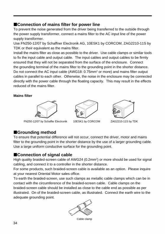
Connection of mains filter for power lineTo prevent the noise generated from the driver being transferred to the outside throughthe power supply transformer, connect a mains filter to the AC input line of the powersupply transformer.Use FN250-12/07 by Schaffner Electronik AG, 10ESK1 by CORCOM, ZAG2210-11S byTDK or their equivalent as the mains filter.Install the mains filter as close as possible to the driver. Use cable clamps or similar toolsto fix the input cable and output cable. The input cables and output cables to be firmlyensured that they will not be separated from the surface of the enclosure. Connectthe grounding terminal of the mains filter to the grounding point in the shorter distance.Do not connect the AC input cable (AWG18: 0.75mm2 or more) and mains filter outputcables in parallel to each other. Otherwise, the noise in the enclosure may be connecteddirectly with the power cable through the floating capacity. This may result in the effectsreduced of the mains filter.
Mains filter
Grounding methodTo ensure that potential difference will not occur, connect the driver, motor and mainsfilter to the grounding point in the shorter distance by the use of a larger grounding cable.Use a large uniform conductive surface for the grounding point.
FN250-12/07 by Schaffer Electronik 10ESK1 by CORCOM ZAG2210-11S by TDK
Connection of signal cableHigh quality braided-screen cable of AWG24 (0.2mm2) or more should be used for signalcabling, and connect it to a controller in the shorter distance.For some products, such braided-screen cable is available as an option. Please inquireat your nearest Oriental Motor sales office.To earth the braided-screen, use such clamps as metallic cable clamps which can be incontact with the circumference of the braided-screen cable. Cable clamps on thebraided-screen cable should be installed as close to the cable end as possible as perillustrated. On of the braided-screen cable, as illustrated. Connect the earth wire to theadequate grounding point.
Cable clamp

35
Others• To ensure that potential difference will not occur between the motor/driver and
peripheral control system equipment, earth the cable directly to the grounding point.• When the relay and magnetic switch are used together, make sure that the surge is
absorbed by the mains filter and CR circuit.• The length of the cables should be as short as possible; do not use long cables with the
excess portion wound in a bundle.• Keep the power cables such as the motor cable and power cable away from the signal
cables and connect them separately from each other as far as possible [For example,keep them 100 to 200mm (3.94 to 7.87in.) apart from each other]. Signal cables shouldonly cross the path of motor or power cables at right angle. The AC input cable andoutput cable of the mains filter should be kept away from each other.
Precautions concerning static electricityStatic electricity can make the driver malfunction or destroy it. Handle the driver carefullywhen its power is on.Always use an insulated screwdriver when adjusting the motor current with the driver’sinternal control (VR) or switch.When using a driver mounted on the current check terminals, adjust the current in thefollowing manner.1.Switch off the driver power supply.2. Insert the tester into the current check terminals.3.Switch on the driver power supply.4.Adjust the current by adjusting the internal control (VR) with an insulated screwdriver.5.Switch off the driver power supply, then remove the tester.Note: Do not approach or touch the driver with the power on.
Motor
Driver Controller
FG FG
FG
P.E.
FG FG
A A
A A
FGBraided-screen
cable
B C
Grounded panel
P.E.A: Cable clampB: Mains filterC: DC power supply
The standard length of the motor cable is 23.6in. (600mm).The length of the cable between the driver and controller is 78in. (2,000mm).
Example of motor and driver installation and wiring

2
• Please contact your nearest Oriental Motor office for further information.
Printed on Recycled Paper
Technical Support Line Tel:(800)468-3982
Available from 7:30 AM to 5:00 PM, P.S.T.
E-mail: [email protected]
www.orientalmotor.com
Headquarters and Düsseldorf Office
Tel:0211-5206700 Fax:0211-52067099
Munich Office
Tel:08131-59880 Fax:08131-598888
Hamburg Office
Tel:040-76910443 Fax:040-76910445
Tel:01256-347090 Fax:01256-347099
Tel:01 47 86 97 50 Fax:01 47 82 45 16
Tel:02-93906346 Fax:02-93906348
Tel:(02)8228-0707 Fax:(02)8228-0708
Tel:(6745)7344 Fax:(6745)9405
Tel:(03)22875778 Fax:(03)22875528
KOREA
Tel:(032)822-2042~3 Fax:(032)819-8745
Headquarters Tokyo, Japan
Tel:(03)3835-0684 Fax:(03)3835-1890
• Unauthorized reproduction or copying of all or part of this operating manual isprohibited.If a new copy is required to replace an original manual that has been damaged or lost,please contact your nearest branch or sales office.
• Oriental Motor shall not be liable whatsoever for any problems relating to industrialproperty rights arising from use of any information, circuit, equipment or deviceprovided or referenced in this manual.
• This Operating Manual is subject to change without prior notice for the purpose ofproduct improvement or changes in specifications, or to improve its general content.
• While we make every effort to offer accurate information in the manual, we welcomeyour input. Should you find unclear descriptions, errors or omissions, please contactthe nearest office.
• is a trademark of Oriental Motor Co., Ltd.All other product names and company names are the trademarks or registeredtrademarks of their respective companies. Any reference made in this operating manualto the names of products manufactured by companies other than Oriental Motor is doneso for reference purposes only and is not intended to enforce or recommend the usethereof. Oriental Motor shall not be liable in anyway whatsoever for the performance oruse of products made by other companies.
Copyright ORIENTAL MOTOR CO., LTD. 2001