compact antenna array of superdirective elements
TRANSCRIPT

HAL Id: hal-01247233https://hal.archives-ouvertes.fr/hal-01247233
Submitted on 21 Dec 2015
HAL is a multi-disciplinary open accessarchive for the deposit and dissemination of sci-entific research documents, whether they are pub-lished or not. The documents may come fromteaching and research institutions in France orabroad, or from public or private research centers.
L’archive ouverte pluridisciplinaire HAL, estdestinée au dépôt et à la diffusion de documentsscientifiques de niveau recherche, publiés ou non,émanant des établissements d’enseignement et derecherche français ou étrangers, des laboratoirespublics ou privés.
Compact Antenna Array of Superdirective ElementsAbdullah Haskou, Ala Sharaiha, Sylvain Collardey
To cite this version:Abdullah Haskou, Ala Sharaiha, Sylvain Collardey. Compact Antenna Array of Superdirective El-ements. IEEE Antennas and Wireless Propagation Letters, Institute of Electrical and ElectronicsEngineers, 2016, 15, pp.1386 - 1389. �10.1109/LAWP.2015.2510382�. �hal-01247233�

1
Compact Antenna Array of Superdirective ElementsAbdullah Haskou, Ala Sharaiha, Senior Member, IEEE, and Sylvain Collardey
Abstract—In this letter, we investigate using a two-elementparasitic (loaded) superdirective antenna as a unit-elementto achieve a compact 3D array. Four elements of a planarparasitic superdirective antenna are integrated in a compact2 × 2 array for UHF band. The array final dimensions are200 × 200 × 70mm3(0.58λ × 0.58λ × 0.2λ), and it presents amaximum simulated total directivity of 11.4dBi. The antennadimensions are significantly smaller than classical commercialarrays achieving the same directivity. The measured results arein a good agreement with the simulated ones.
Keywords—Antenna array, superdirectivity, PCB, radiation effi-ciency, directivity
I. INTRODUCTION
SOME emerging wireless technologies require accurate beampointing that can only be achieved using antenna arrays.
The main parameter determining the size of an array is thespacing between adjacent radiators, which is typically chosento be half a wavelength. Reducing the spacing introduces mu-tual coupling between the elements and, hence, a degradationof the radiation pattern and the gain of the antenna. To makeultimate use of all available degrees of freedom for a givennumber of radiators, superdirective elements must be taken intoconsideration, though at the expense of reduced bandwidth andhigh sensitivity to variations in component values.Since the early work of I. Uzkov [1], a significant research wasdone on the design of superdirective arrays [2]-[6]. Early worksfocused on the design of superdirective 3D wire antennas [2]-[3]. Two-element supergain Electrically Small Antenna (ESA)arrays were studied in [4]. Later, multiple printed end-fireparasitic superdirective ESAs were presented [5]-[6].In our previous works we have detailed the design methodol-ogy of parasitic superdirective arrays and the tradeoff betweenthe maximum directivity and radiation efficiency in [6]. Theintegration of two-element electrically small parasitic arraysin PCBs was investigated in [7] where we modify the PCBby including a slot in order to maintain the superdirectivity.Finally, the effect of the excitation cable on measuring PCB-mounted arrays was investigated in [8]. In this letter, weinvestigate using parasitic (loaded) superdirective antennasas unit-elements to realize compact 3D broadside arrays. Aparametric analysis on the inter-element distance demonstratesthe necessary tradeoff between the antenna- dimensions, -directivity and -radiation efficiency. Although this work isbased on two-element array, it can be generalized to N-elementarrays. 1 The rest of the paper is organized as follows: simula-
Manuscript received August 24, 2015; revised November 9, 2015.The authors are with IETR UMR CNRS 6164- Université de Rennes 1,
35042 Rennes Cedex, France. e-mail: ([email protected]).1This work was done with the funding of the French National Research
Agency as part of the project "SOCRATE" and the support of the "Images etReseaux" cluster of Brittany region, France.
tion results are presented in section II. Array dimensions effectis studied in section III. Results are validated via measurementsin section IV. Finally, section V provides some concludingremarks.
II. GEOMETRY AND SIMULATION RESULTS
A. Unit-Element DesignThe approaches presented in [6], was applied to design a
two-element parasitic array integrated in a PCB for 869MHzfrequency band. The array is based on an electrically smallhalf-loop antenna printed on a 0.8mm-thick Rogers RO4003(ϵr = 3.55, tan(δ) = 0.0027) substrate. Fig. 1(a) shows arraygeometry and dimensions in millimeters. In this array, excitingthe second element and loading the first one with an inductorof 4.3nH , a maximum simulated (HFSS [9]) directivity of7dBi is achieved as shown in Fig. 1(b). This directivity is1.8dB greater than Harrington’s normal directivity limit ofan antenna with the same dimensions (ka = 1.08), wherea is the radius of the smallest sphere enclosing the antennaand k = 2π/λ is the wave number [10]. The Half PowerBeam-Width (HPBW) in horizontal and vertical planes (XOYand YOZ) are respectively 76◦ and 108◦, and the Front ToBack Ratio (FBR) is 6.4dB. Furthermore, the radiation patterndoes not have any side lobes. Fig. 1(c) shows that antenna’send-fire total directivity (D(θ=90o,ϕ=90o)) is maximal aroundthe resonance frequency of 869MHz. The antenna achievesan impedance bandwidth (S11 < −6dB) of 2.3MHz anddirectivity bandwidth of (Dmax − 1dB) of 4.3MHz. Finally,Fig. 1(d) shows the antenna surface current distribution at theresonance frequency. As it can be noticed, the current on thetwo elements is on phase opposition which is the condition forhaving superdirectivity for very small inter-element distances.Due to this current opposition, the antenna presents a relativelylow simulated radiation efficiency of 45.6% (a gain of 3.6dBi).
B. 3D Array DesignFour of the end-fire antenna presented in subsection A are
arranged as shown in Fig. 2(a) where the two antennas in thesame plane are inverted to increase the distance between theradiating elements. Then, to achieve the maximum directivityin oY direction, this inversion is compensated by a 180o phaseshift in their excitation (elements 1 and 3 are excited out ofphase comparing to elements 2 and 4). The separating distance(measured between the feeding points) is 152mm on x-axisand 200mm on z-axis. Hence, the array total dimensions are200 × 200 × 70mm3. As it can be seen from the antennasimulated 3D total directivity radiation pattern given in Fig.2(b), the antenna has a directive pattern with a maximumtotal directivity of 11.4dBi. The HPBW in horizontal andvertical planes are respectively 56◦ and 48◦, and the FBR is

2
13.2dB. The radiation pattern has four side lobes with a SideLobe Level (SLL) of −8.3dBi. Fig. 2(c) shows that antenna’sbroadside total directivity (D(θ=90o,ϕ=90o)) is maximal aroundthe resonance frequency of 869MHz (the input reflectioncoefficient of the four elements are identical so only one isshown). The antenna has an impedance bandwidth of 1MHzand a directivity one of 8.7MHz. Comparing with the end-firearray, it can be noticed that the array maximum total directivityis increased by 4.4dBi, the horizontal HPBW is divided by 1.4,and vertical HPBW is divided by 2.3. The limited improvementin horizontal HPBW is due to the smaller separation in thisplane, and hence, a higher mutual coupling as it can be seenin Fig. 2(d).
(a) (b)
830 840 850 860 870 880 890 900−10
−5
0
Frequency [MHz]
S11
[dB
]
830 840 850 860 870 880 890 9000
2
4
6
8
10
12
End
−F
ire D
irect
ivity
[dB
i]
(c)
(d)
Fig. 1. End-fire array geometry and simulated parameters. (a) Geometryand dimensions, (b) 3D total directivity radiation pattern, (c) input reflectioncoefficient magnitude in dB and broadside directivity and (d) surface currentdistribution.
(a) (b)
830 840 850 860 870 880 890 900−10
−5
0
Frequency [MHz]S
11 [d
B]
830 840 850 860 870 880 890 9000
2
4
6
8
10
12
Bro
adsi
de D
irect
ivity
[dB
i]
(c)
830 840 850 860 870 880 890 900−60
−50
−40
−30
−20
−10
0
Frequency [MHz]
Sij [d
B]
S12
S13
S14
(d)
Fig. 2. Broadside array geometry and simulated parameters. (a) Geometryand dimensions, (b) 3D total directivity radiation pattern, (c) input reflectioncoefficient magnitude in dB and broadside directivity and (d) mutual couplingmagnitude in dB.
III. DISTANCE EFFECT
We vary the array distance (d) from 0.01λ to λ whilemonitoring the antenna input reflection coefficient, total di-rectivity and radiation efficiency. Fig. 3(a) shows the arraysimulated input reflection coefficient magnitude in dB as afunction of the distance. The figure shows that for d = 0.01λthe array is completely unmatched in the observed frequencyband. This is due to the high mutual coupling. As the distanceincreases the mutual coupling decreases and the array reso-nance frequency converges to the one of the unit-elements.

3
Fig. 3(b) shows the array simulated maximum total directivityand radiation efficiency as a function of the distance. For verysmall distances, due to the high mutual coupling, the appliedloads are not suitable anymore and superdirectivity effect islost, and hence, the radiation efficiency is maximal. As thedistance increases, the superdirectivity effect appears and theradiation efficiency decreases. As expected, we can note thatas the distance increases, the achieved directivity increasestill 0.7λ when it starts decreasing again [11]. Fig. 4 showsarray 2D total directivity radiation patterns in horizontal andvertical planes at the design frequency (869MHz) for severaldistances. For distances greater than 0.5λ side lobes appearin the vertical plane and as the distance increases the SLLalso increases, where increasing the distance from 0.5λ to λincreases the SLL from −12.8dBi to 6.7dBi. We chose torealize the antenna with d = 0.6λ due to a constraint on theantenna dimensions.
830 840 850 860 870 880 890 900−10
−8
−6
−4
−2
0
Frequency [MHz]
S11
[dB
]
0.01λ0.2λ0.4λ0.8λ
(a)
0 0.2 0.4 0.6 0.8 160
65
70
75
80
85
90
η rad [%
]
d/λ0 0.2 0.4 0.6 0.8 1
0
2
4
6
8
10
12
Dm
ax [d
Bi]
(b)
Fig. 3. Broadside array simulated parameters as a function of the distance.(a) Input reflection coefficient magnitude in dB and (b) total directivity andradiation efficiency.
−25
−15
−5
5
15
30
210
60
240
90
270
120
300
150
330
180 0
φ [°]
Dire
ctiv
ity [d
Bi]
0.01λ0.2λ0.4λ0.8λ
(a)
−25
−15
−5
5
15
30
210
60
240
90
270
120
300
150
330
180 0
θ [°]
Dire
ctiv
ity [d
Bi]
0.01λ0.2λ0.4λ0.8λ
(b)
Fig. 4. Broadside array simulated 2D total directivity radiation patterns as afunction of the distance. (a) Horizontal plane and (b) vertical plane.
IV. MEASUREMENT RESULTS
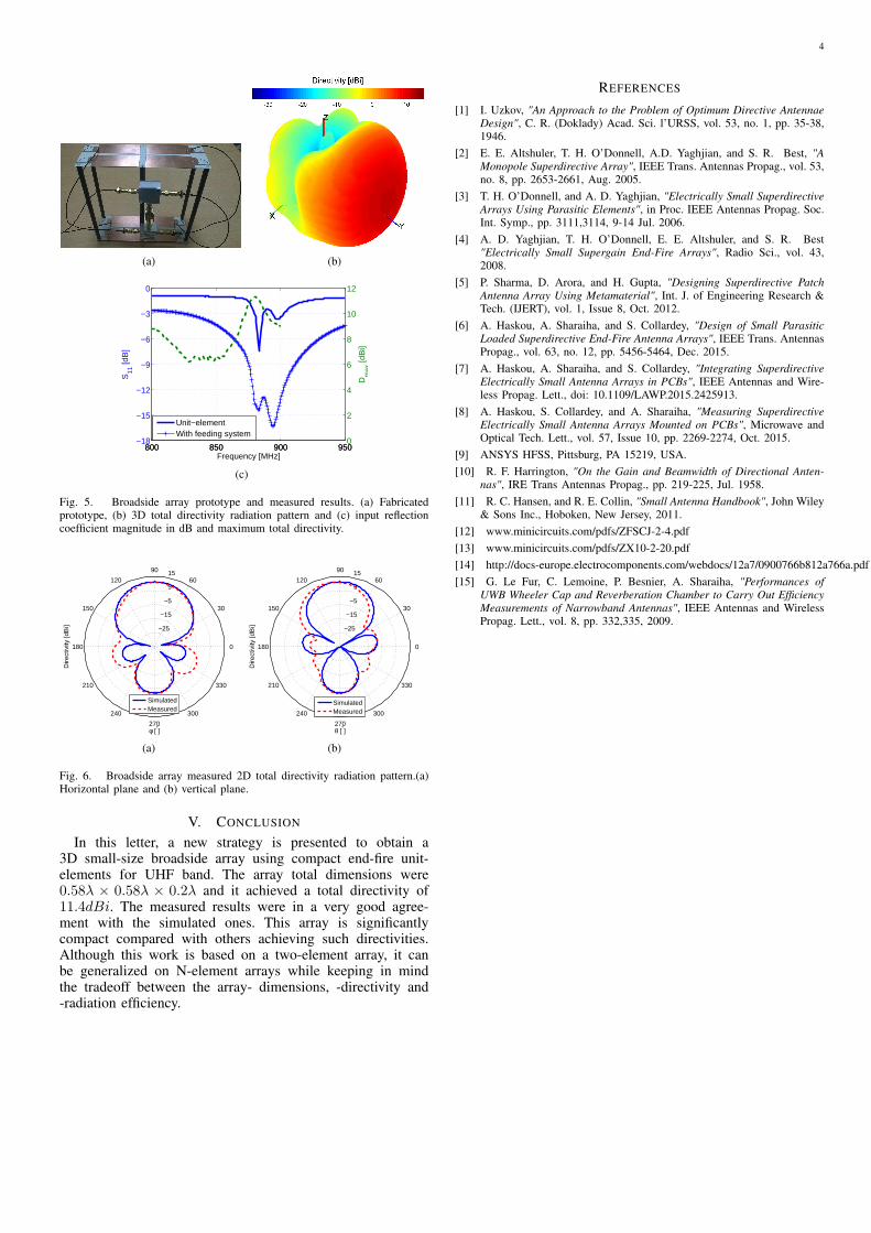
Fig. 5(a) shows a photograph of the realized prototypeof the broadside array. The feeding system is composed ofone ZFSCJ-2-4+ power splitter [12], two ZX10-2-20+ powersplitter-shifter [13] and four 30cm-long UFL cables [14]. Theantenna far-field radiation pattern was measured in SATIMOstargate (SG 32) near-field measurement system. The measured3D total directivity radiation pattern at the resonance frequencyis given in Fig. 5(b). The figure shows a maximum total direc-tivity of 11.3dBi in the broadside direction (towards oY). Fig.5(c) shows measured input reflection coefficient magnitude forthe unit-elements and the antenna with the feeding system aswell as the maximum total directivity versus frequency. Themeasured resonance frequency of the unit-elements is around883MHz (a frequency shift of 1.8%). This shift is probablydue to the antenna environment (UFL cable effect, SMAconnector and the dispersion of the commercial SMD loads).We can note that the feeding system presents an approximateinsertion loss of 3.5dB at the resonance frequency. This lossis distributed as follows: 1.5dB in the splitter, 0.6dB inthe splitter-shifter, 1dB in the UFL cable and 0.4dB in theconnectors. The antenna (without the feeding system) has animpedance bandwidth of 1.9MHz. The figure also showsthat the antenna directivity is maximal around the resonancefrequency with a directivity bandwidth of 13.5MHz. Fig. 6(a)and Fig. 6(b) show measured 2D total directivity radiationpatterns. The HPBW in both horizontal and vertical planes are56◦, the FBR is 12.4dB and SLL is −2.6dBi. The measuredpattern is in a very good agreement with the simulated one inthe main-beam direction. The small difference in the backwarddirection may be attributed to the measuring system andenvironment. The antenna radiation efficiency measured in areverberation chamber [15], after compensating the losses inthe feeding system, is about 58%, and hence. the antennameasured gain is 8.9dBi.
4
(a) (b)
800 850 900 950−18
−15
−12
−9
−6
−3
0
S11
[dB
]
Frequency [MHz]
800 850 900 9500
2
4
6
8
10
12
Dm
ax [d
Bi]
Unit−elementWith feeding system
(c)
Fig. 5. Broadside array prototype and measured results. (a) Fabricatedprototype, (b) 3D total directivity radiation pattern and (c) input reflectioncoefficient magnitude in dB and maximum total directivity.
−25
−15
−5
5
15
30
210
60
240
90
270
120
300
150
330
180 0
φ [°]
Dire
ctiv
ity [d
Bi]
SimulatedMeasured
(a)
−25
−15
−5
5
15
30
210
60
240
90
270
120
300
150
330
180 0
θ [°]
Dire
ctiv
ity [d
Bi]
SimulatedMeasured
(b)
Fig. 6. Broadside array measured 2D total directivity radiation pattern.(a)Horizontal plane and (b) vertical plane.
V. CONCLUSION
In this letter, a new strategy is presented to obtain a3D small-size broadside array using compact end-fire unit-elements for UHF band. The array total dimensions were0.58λ × 0.58λ × 0.2λ and it achieved a total directivity of11.4dBi. The measured results were in a very good agree-ment with the simulated ones. This array is significantlycompact compared with others achieving such directivities.Although this work is based on a two-element array, it canbe generalized on N-element arrays while keeping in mindthe tradeoff between the array- dimensions, -directivity and-radiation efficiency.
REFERENCES
[1] I. Uzkov, "An Approach to the Problem of Optimum Directive AntennaeDesign", C. R. (Doklady) Acad. Sci. l’URSS, vol. 53, no. 1, pp. 35-38,1946.
[2] E. E. Altshuler, T. H. O’Donnell, A.D. Yaghjian, and S. R. Best, "AMonopole Superdirective Array", IEEE Trans. Antennas Propag., vol. 53,no. 8, pp. 2653-2661, Aug. 2005.
[3] T. H. O’Donnell, and A. D. Yaghjian, "Electrically Small SuperdirectiveArrays Using Parasitic Elements", in Proc. IEEE Antennas Propag. Soc.Int. Symp., pp. 3111,3114, 9-14 Jul. 2006.
[4] A. D. Yaghjian, T. H. O’Donnell, E. E. Altshuler, and S. R. Best"Electrically Small Supergain End-Fire Arrays", Radio Sci., vol. 43,2008.
[5] P. Sharma, D. Arora, and H. Gupta, "Designing Superdirective PatchAntenna Array Using Metamaterial", Int. J. of Engineering Research &Tech. (IJERT), vol. 1, Issue 8, Oct. 2012.
[6] A. Haskou, A. Sharaiha, and S. Collardey, "Design of Small ParasiticLoaded Superdirective End-Fire Antenna Arrays", IEEE Trans. AntennasPropag., vol. 63, no. 12, pp. 5456-5464, Dec. 2015.
[7] A. Haskou, A. Sharaiha, and S. Collardey, "Integrating SuperdirectiveElectrically Small Antenna Arrays in PCBs", IEEE Antennas and Wire-less Propag. Lett., doi: 10.1109/LAWP.2015.2425913.
[8] A. Haskou, S. Collardey, and A. Sharaiha, "Measuring SuperdirectiveElectrically Small Antenna Arrays Mounted on PCBs", Microwave andOptical Tech. Lett., vol. 57, Issue 10, pp. 2269-2274, Oct. 2015.
[9] ANSYS HFSS, Pittsburg, PA 15219, USA.[10] R. F. Harrington, "On the Gain and Beamwidth of Directional Anten-
nas", IRE Trans Antennas Propag., pp. 219-225, Jul. 1958.[11] R. C. Hansen, and R. E. Collin, "Small Antenna Handbook", John Wiley
& Sons Inc., Hoboken, New Jersey, 2011.[12] www.minicircuits.com/pdfs/ZFSCJ-2-4.pdf[13] www.minicircuits.com/pdfs/ZX10-2-20.pdf[14] http://docs-europe.electrocomponents.com/webdocs/12a7/0900766b812a766a.pdf[15] G. Le Fur, C. Lemoine, P. Besnier, A. Sharaiha, "Performances of
UWB Wheeler Cap and Reverberation Chamber to Carry Out EfficiencyMeasurements of Narrowband Antennas", IEEE Antennas and WirelessPropag. Lett., vol. 8, pp. 332,335, 2009.