communication server 1000m and meridian 1 large system
TRANSCRIPT

Nortel Networks Communication Server 1000Nortel Networks Communication Server 1000 Release 4.0
Communication Server 1000M and Meridian 1Large System Maintenance
Document Number: 553-3021-500Document Release: Standard 2.00Date: September 2004
Year Publish FCC TMCopyright © 2003–2004 Nortel NetworksAll Rights Reserved
Produced in Canada
Information is subject to change without notice. Nortel Networks reserves the right to make changes in design or components as progress in engineering and manufacturing may warrant.
SL-1, Meridian 1, and Succession are trademarks of Nortel Networks.
Title page


Page 3 of 432
Communication Server 1000M and Meridian 1 Large System Maintenance
4
Revision historySeptember 2004
Standard 2.00. This document is up-issued for Communication Server 1000 Release 4.0.
October 2003Standard 1.00. This document is a new NTP for Succession 3.0. It was created to support a restructuring of the Documentation Library, which resulted in the merging of multiple legacy NTPs. This new document consolidates information previously contained in the following legacy documents, now retired:
• General Maintenance (553-3001-500)
• Fault Clearing (553-3001-510)
• Hardware Replacement (553-3001-520)
Page 4 of 432 Revision history
553-3021-500 Standard 2.00 September 2004

Page 5 of 432
Communication Server 1000M and Meridian 1 Large System Maintenance
10
Contents
About this document . . . . . . . . . . . . . . . . . . . . . . . 11Subject . . . . . . . . . . . . . . . . . . . . . . . . . . . . . . . . . . . . . . . . . . . . . . . . . . 11
Applicable systems . . . . . . . . . . . . . . . . . . . . . . . . . . . . . . . . . . . . . . . . 11
Intended audience . . . . . . . . . . . . . . . . . . . . . . . . . . . . . . . . . . . . . . . . . 12
Conventions .. . . . . . . . . . . . . . . . . . . . . . . . . . . . . . . . . . . . . . . . . . . . . 13
Related information .. . . . . . . . . . . . . . . . . . . . . . . . . . . . . . . . . . . . . . . 13
Communicating with the system . . . . . . . . . . . . . . 17Contents .. . . . . . . . . . . . . . . . . . . . . . . . . . . . . . . . . . . . . . . . . . . . . . . . 17
Overview . . . . . . . . . . . . . . . . . . . . . . . . . . . . . . . . . . . . . . . . . . . . . . . . 17
System terminal .. . . . . . . . . . . . . . . . . . . . . . . . . . . . . . . . . . . . . . . . . . 17
Maintenance telephone . . . . . . . . . . . . . . . . . . . . . . . . . . . . . . . . . . . . . 24
How to clear faults . . . . . . . . . . . . . . . . . . . . . . . . . 27Contents .. . . . . . . . . . . . . . . . . . . . . . . . . . . . . . . . . . . . . . . . . . . . . . . . 27
Fault clearing process . . . . . . . . . . . . . . . . . . . . . . . . . . . . . . . . . . . . . . 27
Using this document . . . . . . . . . . . . . . . . . . . . . . . . . . . . . . . . . . . . . . . 28
Fault indicators . . . . . . . . . . . . . . . . . . . . . . . . . . . . . . . . . . . . . . . . . . . 29
Clearing power faults . . . . . . . . . . . . . . . . . . . . . . . 37Contents .. . . . . . . . . . . . . . . . . . . . . . . . . . . . . . . . . . . . . . . . . . . . . . . . 37
Power faults .. . . . . . . . . . . . . . . . . . . . . . . . . . . . . . . . . . . . . . . . . . . . . 37
Fault clearing procedures . . . . . . . . . . . . . . . . . . . . . . . . . . . . . . . . . . . 40
Candeo power systems . . . . . . . . . . . . . . . . . . . . . . . . . . . . . . . . . . . . . 58

Page 6 of 432 Contents
553-3021-500 Standard 2.00 September 2004
Clearing common equipment faults . . . . . . . . . . . 61Contents . . . . . . . . . . . . . . . . . . . . . . . . . . . . . . . . . . . . . . . . . . . . . . . . 61
Common equipment faults . . . . . . . . . . . . . . . . . . . . . . . . . . . . . . . . . . 61
Fault clearing procedures . . . . . . . . . . . . . . . . . . . . . . . . . . . . . . . . . . . 62
Clearing network equipment faults . . . . . . . . . . . . 73Contents . . . . . . . . . . . . . . . . . . . . . . . . . . . . . . . . . . . . . . . . . . . . . . . . 73
Network equipment faults .. . . . . . . . . . . . . . . . . . . . . . . . . . . . . . . . . . 73
Fault clearing procedures . . . . . . . . . . . . . . . . . . . . . . . . . . . . . . . . . . . 74
Clearing peripheral equipment faults . . . . . . . . . . 99Contents . . . . . . . . . . . . . . . . . . . . . . . . . . . . . . . . . . . . . . . . . . . . . . . . 99
Peripheral equipment faults . . . . . . . . . . . . . . . . . . . . . . . . . . . . . . . . . 99
Fault clearing procedures . . . . . . . . . . . . . . . . . . . . . . . . . . . . . . . . . . . 100
Clearing trunk faults . . . . . . . . . . . . . . . . . . . . . . . . 113Contents . . . . . . . . . . . . . . . . . . . . . . . . . . . . . . . . . . . . . . . . . . . . . . . . 113
Trunk faults . . . . . . . . . . . . . . . . . . . . . . . . . . . . . . . . . . . . . . . . . . . . . . 113
Fault clearing procedures . . . . . . . . . . . . . . . . . . . . . . . . . . . . . . . . . . . 115
Clearing attendant console faults . . . . . . . . . . . . . 121Contents . . . . . . . . . . . . . . . . . . . . . . . . . . . . . . . . . . . . . . . . . . . . . . . . 121
Attendant console faults . . . . . . . . . . . . . . . . . . . . . . . . . . . . . . . . . . . . 121
Fault clearing procedures . . . . . . . . . . . . . . . . . . . . . . . . . . . . . . . . . . . 122
Clearing telephone faults . . . . . . . . . . . . . . . . . . . . 131Contents . . . . . . . . . . . . . . . . . . . . . . . . . . . . . . . . . . . . . . . . . . . . . . . . 131
Telephone faults . . . . . . . . . . . . . . . . . . . . . . . . . . . . . . . . . . . . . . . . . . 131
Fault clearing procedures . . . . . . . . . . . . . . . . . . . . . . . . . . . . . . . . . . . 132
Simple Network Management Protocol . . . . . . . . 149Contents . . . . . . . . . . . . . . . . . . . . . . . . . . . . . . . . . . . . . . . . . . . . . . . . 149
Introduction .. . . . . . . . . . . . . . . . . . . . . . . . . . . . . . . . . . . . . . . . . . . . . 150

Contents Page 7 of 432
Communication Server 1000M and Meridian 1 Large System Maintenance
Configuration . . . . . . . . . . . . . . . . . . . . . . . . . . . . . . . . . . . . . . . . . . . . 152
Supported MIBs . . . . . . . . . . . . . . . . . . . . . . . . . . . . . . . . . . . . . . . . . . 154
Configuration of system group MIB parameters .. . . . . . . . . . . . . . . . . 155
Traffic MIB . . . . . . . . . . . . . . . . . . . . . . . . . . . . . . . . . . . . . . . . . . . . . . 160
Community name strings . . . . . . . . . . . . . . . . . . . . . . . . . . . . . . . . . . . 160
Test Alarm utility . . . . . . . . . . . . . . . . . . . . . . . . . . . . . . . . . . . . . . . . . 162
EDT and EPT . . . . . . . . . . . . . . . . . . . . . . . . . . . . . . . . . . . . . . . . . . . . 164
Backup and restore . . . . . . . . . . . . . . . . . . . . . . . . . . . . . . . . . . . . . . . . 165
More information . . . . . . . . . . . . . . . . . . . . . . . . . . . . . . . . . . . . . . . . . 166
Proactive Voice-quality Management . . . . . . . . . . 167Contents .. . . . . . . . . . . . . . . . . . . . . . . . . . . . . . . . . . . . . . . . . . . . . . . . 167
Introduction . . . . . . . . . . . . . . . . . . . . . . . . . . . . . . . . . . . . . . . . . . . . . . 168
How voice quality monitoring works . . . . . . . . . . . . . . . . . . . . . . . . . . 169
Feature packaging . . . . . . . . . . . . . . . . . . . . . . . . . . . . . . . . . . . . . . . . . 171
Supported system types . . . . . . . . . . . . . . . . . . . . . . . . . . . . . . . . . . . . . 171
Feature implementation .. . . . . . . . . . . . . . . . . . . . . . . . . . . . . . . . . . . . 171
New voice-quality alarms . . . . . . . . . . . . . . . . . . . . . . . . . . . . . . . . . . . 180
Diagnosing and isolating voice-quality problems . . . . . . . . . . . . . . . . . 181
SNMP interface . . . . . . . . . . . . . . . . . . . . . . . . . . . . . . . . . . . . . . . . . . . 182
Heterogeneous environments . . . . . . . . . . . . . . . . . . . . . . . . . . . . . . . . 182
pbxLink connection failure detection and status reporting enhancement . . . . . . . . . . . . . . . . . . . . . 185Contents .. . . . . . . . . . . . . . . . . . . . . . . . . . . . . . . . . . . . . . . . . . . . . . . . 185
Introduction . . . . . . . . . . . . . . . . . . . . . . . . . . . . . . . . . . . . . . . . . . . . . . 185
pbxLink connection failure detection . . . . . . . . . . . . . . . . . . . . . . . . . . 186
LD 117 STAT SERV enhancement . . . . . . . . . . . . . . . . . . . . . . . . . . . 186
Final maintenance procedure . . . . . . . . . . . . . . . . 193Introduction . . . . . . . . . . . . . . . . . . . . . . . . . . . . . . . . . . . . . . . . . . . . . . 193

Page 8 of 432 Contents
553-3021-500 Standard 2.00 September 2004
Software maintenance tools . . . . . . . . . . . . . . . . . 197Contents . . . . . . . . . . . . . . . . . . . . . . . . . . . . . . . . . . . . . . . . . . . . . . . . 197
Diagnostic programs . . . . . . . . . . . . . . . . . . . . . . . . . . . . . . . . . . . . . . . 197
System features . . . . . . . . . . . . . . . . . . . . . . . . . . . . . . . . . . . . . . . . . . . 202
History file feature . . . . . . . . . . . . . . . . . . . . . . . . . . . . . . . . . . . . . . . . 203
Interactive diagnostics . . . . . . . . . . . . . . . . . . . . . . . . . . . . . . . . . . . . . 204
Hardware replacement guidelines . . . . . . . . . . . . 209Contents . . . . . . . . . . . . . . . . . . . . . . . . . . . . . . . . . . . . . . . . . . . . . . . . 209
Precautions . . . . . . . . . . . . . . . . . . . . . . . . . . . . . . . . . . . . . . . . . . . . . . 209
System cable guidelines . . . . . . . . . . . . . . . . . . . . . . . . . . . . . . . . . . . . 213
Hardware maintenance tools . . . . . . . . . . . . . . . . . 215Contents . . . . . . . . . . . . . . . . . . . . . . . . . . . . . . . . . . . . . . . . . . . . . . . . 215
Overview .. . . . . . . . . . . . . . . . . . . . . . . . . . . . . . . . . . . . . . . . . . . . . . . 215
Circuit card features . . . . . . . . . . . . . . . . . . . . . . . . . . . . . . . . . . . . . . . 216
CPU controls .. . . . . . . . . . . . . . . . . . . . . . . . . . . . . . . . . . . . . . . . . . . . 223
System alarms . . . . . . . . . . . . . . . . . . . . . . . . . . . . . . . . . . . . . . . . . . . . 227
System monitor indicators . . . . . . . . . . . . . . . . . . . . . . . . . . . . . . . . . . 229
Routine maintenance . . . . . . . . . . . . . . . . . . . . . . . 237Contents . . . . . . . . . . . . . . . . . . . . . . . . . . . . . . . . . . . . . . . . . . . . . . . . 237
Pedestal air filter . . . . . . . . . . . . . . . . . . . . . . . . . . . . . . . . . . . . . . . . . . 237
DC-power battery systems . . . . . . . . . . . . . . . . . . . . . . . . . . . . . . . . . . 238
Replacing equipment . . . . . . . . . . . . . . . . . . . . . . . 239Content list . . . . . . . . . . . . . . . . . . . . . . . . . . . . . . . . . . . . . . . . . . . . . . 239
Removing module covers and pedestal grills . . . . . . . . . . . . . . . . . . . . 241
NT1P61 Fiber Superloop Network Card . . . . . . . . . . . . . . . . . . . . . . . 243
NT1P62 Fiber Peripheral Controller Card . . . . . . . . . . . . . . . . . . . . . . 245
NT4N43 cPCI Multi-Media Disk Unit . . . . . . . . . . . . . . . . . . . . . . . . . 246
NT4N65, and NT4N66 cPCI Core Network Interface Cards . . . . . . . . 258
Contents Page 9 of 432
Communication Server 1000M and Meridian 1 Large System Maintenance
NT4N67 and NT4N68 System Utility cards . . . . . . . . . . . . . . . . . . . . . 264
NT4N64, and A0810496 Call Processor (CP PII) card . . . . . . . . . . . . 268
NT5D10 68060 Call Processor (CP) Card . . . . . . . . . . . . . . . . . . . . . . 270
NT5D12AA Dual DTI/PRI (DDP) . . . . . . . . . . . . . . . . . . . . . . . . . . . . 278
NT5D61 Input/Output Disk Unit with CD-ROM (IODU/C) . . . . . . . . 281
NT5D61 IODU/C Security Device . . . . . . . . . . . . . . . . . . . . . . . . . . . . 288
NT5D2103 Core/Network Card Cage .. . . . . . . . . . . . . . . . . . . . . . . . . 291
NT5K09 Quad Digitone Receiver .. . . . . . . . . . . . . . . . . . . . . . . . . . . . 302
NT5K10 Dual Loop Peripheral Buffer Card .. . . . . . . . . . . . . . . . . . . . 303
NT5K1106 Enhanced Peripheral Equipment Card Cage . . . . . . . . . . . 305
NT5K21AA Extended Multi - Frequency Compelled Sender/Receiver Card . . . . . . . . . . . . . . . . . . . . . . . . . . . . . 308
NT6D40, NT6D41, NT6D42, Power Supply DC . . . . . . . . . . . . . . . . . 309
NT6D65 and NTRB34 Core to Network Interface Cards .. . . . . . . . . . 310
NT7D10 Power Distribution Unit DC . . . . . . . . . . . . . . . . . . . . . . . . . 313
NT7D67CB Power Distribution Unit DC . . . . . . . . . . . . . . . . . . . . . . 318
NT7R51 Local Carrier Interface Card . . . . . . . . . . . . . . . . . . . . . . . . . 323
NT7R52 Remote Carrier Interface Card . . . . . . . . . . . . . . . . . . . . . . . . 324
NT8D01 Controller Card . . . . . . . . . . . . . . . . . . . . . . . . . . . . . . . . . . . 325
NT8D02, NT8D03, NT8D09, NT8D14, NT8D15, NT8D16Intelligent Peripheral Equipment Card . . . . . . . . . . . . . . . . . . . . . . . . . 327
NT8D04 Superloop Network Card, QPC414 Network Card . . . . . . . . 330
NT8D06, NT8D21, NT8D29 Power Supply AC . . . . . . . . . . . . . . . . . 332
NT8D17 Conference/TDS Card . . . . . . . . . . . . . . . . . . . . . . . . . . . . . . 334
NT8D22 System Monitor . . . . . . . . . . . . . . . . . . . . . . . . . . . . . . . . . . . 335
NT8D41 Dual or Quad Port Serial Data Interface card . . . . . . . . . . . . 337
NT8D46AC Thermostat Harness . . . . . . . . . . . . . . . . . . . . . . . . . . . . . 339
NT8D46AM, NT8D46DC Air Probe Harness . . . . . . . . . . . . . . . . . . . 345
NT8D52AB, NT8D52DD Pedestal Blower Unit . . . . . . . . . . . . . . . . . 348
NT8D53CA Power Distribution Unit AC . . . . . . . . . . . . . . . . . . . . . . . 350
Page 10 of 432 Contents
553-3021-500 Standard 2.00 September 2004
NT8D56AA, NT8D56AC, NT8D57 Module Power Distribution Unit . . . . . . . . . . . . . . . . . . . . . . . . . . . . . . . . . . . . 353
NT8D3503/NT8D3507 Network Module Card Cage . . . . . . . . . . . . . 355
NT8D3703 IPE Module Card Cage . . . . . . . . . . . . . . . . . . . . . . . . . . . 363
NT9D19 68040 Call Processor (CP) Card replacement insystems equipped with NT5D61 IODU/C cards .. . . . . . . . . . . . . . . . . 368
NTAG26 Extended Multi-frequency receiver . . . . . . . . . . . . . . . . . . . 373
NTBK51AA Downloadable D-Channel Daughterboard . . . . . . . . . . . 374
FIJI Card replacement .. . . . . . . . . . . . . . . . . . . . . . . . . . . . . . . . . . . . . 378
P0699798 Air Filter . . . . . . . . . . . . . . . . . . . . . . . . . . . . . . . . . . . . . . . 381
QPC43 Peripheral Signaling Card . . . . . . . . . . . . . . . . . . . . . . . . . . . . 383
QPC441 Three-Port Extender Card . . . . . . . . . . . . . . . . . . . . . . . . . . . 385
QPC471, QPC775 Clock Controller Card . . . . . . . . . . . . . . . . . . . . . . 390
QPC477 Bus Terminating Unit .. . . . . . . . . . . . . . . . . . . . . . . . . . . . . . 393
QPC659 Dual Loop Peripheral Buffer Card .. . . . . . . . . . . . . . . . . . . . 394
QPC841 Serial Data Interface Card . . . . . . . . . . . . . . . . . . . . . . . . . . . 396
Replacing an NT7D10 PDU with an NT7D67CB PDU .. . . . . . . . . . . 398
Technical Assistance service . . . . . . . . . . . . . . . . 407Contents . . . . . . . . . . . . . . . . . . . . . . . . . . . . . . . . . . . . . . . . . . . . . . . . 407
Nortel Networks Technical Assistance Centers . . . . . . . . . . . . . . . . . . 407
Services available . . . . . . . . . . . . . . . . . . . . . . . . . . . . . . . . . . . . . . . . . 410
Requesting assistance . . . . . . . . . . . . . . . . . . . . . . . . . . . . . . . . . . . . . . 413
List of terms . . . . . . . . . . . . . . . . . . . . . . . . . . . . . . 415
Index . . . . . . . . . . . . . . . . . . . . . . . . . . . . . . . . . . . . 419

Page 11 of 432
Communication Server 1000M and Meridian 1 Large System Maintenance
16
About this documentThis document is a global document. Contact your system supplier or your Nortel Networks representative to verify that the hardware and software described are supported in your area.
SubjectThis document describes maintenance for Meridian 1 and CS 1000M systems.
Note on legacy products and releases
This NTP contains information about systems, components, and features that are compatible with Nortel Networks Communication Server 1000 Release 4.0 software. For more information on legacy products and releases, click the Technical Documentation link under Support on the Nortel Networks home page:
http://www.nortelnetworks.com/
Applicable systemsThis document applies to the following systems:
• Communication Server 1000M Half Group (CS 1000M HG)
• Communication Server 1000M Single Group (CS 1000M SG)
• Communication Server 1000M Multi Group (CS 1000M MG)
• Meridian 1 PBX 51C
• Meridian 1 PBX 61C

Page 12 of 432 About this document
553-3021-500 Standard 2.00 September 2004
• Meridian 1 PBX 61C CP PII
• Meridian 1 PBX 81
• Meridian 1 PBX 81C
• Meridian 1 PBX 81C CP PII
Note: When upgrading software, memory upgrades may be required on the Signaling Server, the Call Server, or both.
System migration
When particular Meridian 1 systems are upgraded to run CS 1000 Release 4.0 software and configured to include a Signaling Server, they become CS 1000M systems. Table 1 lists each Meridian 1 system that supports an upgrade path to a CS 1000M system.
For more information, see Communication Server 1000M and Meridian 1: Large System Upgrade Procedures (553-3021-258).
Intended audienceThis document is intended for individuals responsible for maintaining Large Systems.
Table 1Meridian 1 systems to CS 1000M systems
This Meridian 1 system... Maps to this CS 1000M system
Meridian 1 PBX 51C CS 1000M Half Group
Meridian 1 PBX 61C CS 1000M Single Group
Meridian 1 PBX 61C CP PII CS 1000M Single Group
Meridian 1 PBX 81 CS 1000M Multi Group
Meridian 1 PBX 81C CS 1000M Multi Group
Meridian 1 PBX 81C CP PII CS 1000M Multi Group

About this document Page 13 of 432
Communication Server 1000M and Meridian 1 Large System Maintenance
Conventions
Terminology
In this document, the following systems are referred to generically as “system”:
• CS 1000M
• Meridian 1
The following systems are referred to generically as “Large System”:
• Communication Server 1000M Half Group (CS 1000M HG)
• Communication Server 1000M Single Group (CS 1000M SG)
• Communication Server 1000M Multi Group (CS 1000M MG)
• Meridian 1 PBX 51C
• Meridian 1 PBX 61C
• Meridian 1 PBX 61C CP PII
• Meridian 1 PBX 81
• Meridian 1 PBX 81C
• Meridian 1 PBX 81C CP PII
Related informationThis section lists information sources that relate to this document.
NTPs
The following NTPs are referenced in this document:
• Library Navigator: Communication Server 1000 Release 4.0 (553-3001-000)
• Equipment Identification (553-3001-154)
• Circuit Card: Description and Installation (553-3001-211)
• System Management (553-3001-300)

Page 14 of 432 About this document
553-3021-500 Standard 2.00 September 2004
• Features and Services (553-3001-306)
• Software Input/Output: Administration (553-3001-311)
• Telephones and Consoles: Description, Installation, and Operation (553-3001-367)
• ISDN Primary Rate Interface: Features (553-3001-369)
• Software Input/Output: System Messages (553-3001-411)
• Software Input/Output: Maintenance (553-3001-511)
• ISDN Primary Rate Interface: Maintenance (553-3001-517)
• Communication Server 1000M and Meridian 1: Large System Overview (553-3021-010)
• Communication Server 1000M and Meridian 1: Large System Planning and Engineering (553-3021-120)
• Communication Server 1000M and Meridian 1: Large System Installation and Configuration (553-3021-210)
• Communication Server 1000M and Meridian 1: Large System Maintenance (553-3021-500)
Other documentation
The following documentation is referenced in this document:
• Candeo Power System User Guide (P0914425)
• Candeo SP 48300 Power System AP6C55AA User Manual (P7000154)
Online
To access Nortel Networks documentation online, click the Technical Documentation link under Support on the Nortel Networks home page:
http://www.nortelnetworks.com/
About this document Page 15 of 432
Communication Server 1000M and Meridian 1 Large System Maintenance
CD-ROM
To obtain Nortel Networks documentation on CD-ROM, contact your Nortel Networks customer representative.

Page 16 of 432 About this document
553-3021-500 Standard 2.00 September 2004

Page 17 of 432
Communication Server 1000M and Meridian 1 Large System Maintenance
26
Communicating with the system
ContentsThis section contains information on the following topics:
Overview . . . . . . . . . . . . . . . . . . . . . . . . . . . . . . . . . . . . . . . . . . . . . . . . 17
System terminal. . . . . . . . . . . . . . . . . . . . . . . . . . . . . . . . . . . . . . . . . . . 17
Maintenance telephone . . . . . . . . . . . . . . . . . . . . . . . . . . . . . . . . . . . . . 24
OverviewYou can exchange information through system terminals and maintenance telephones. When you replace equipment, you often send commands to the system software in order to disable faulty equipment and to enable and test newly installed equipment.
The Multi User Login feature allows more than one device to interact with the system. Refer to System Management (553-3001-300) for details on using this feature.
System terminalYou can send maintenance commands and receive system messages (status and error messages) by accessing the Central Processing Unit (CPU) through an RS-232 device, such as a video display terminal (VDT) or teletypewriter (TTY).
For most systems, only the code is displayed or printed when the CPU sends system messages. For the interpretation of the code and any required action,

Page 18 of 432 Communicating with the system
553-3021-500 Standard 2.00 September 2004
refer to Software Input/Output: System Messages (553-3001-411). Systems provide the code, a plain text explanation, and required actions.
Enhanced I/O buffering (independent throughout) is provided. With this capability, devices with higher baud rates run faster than devices that are limited to slower speeds.
Access through the system terminal
When you access the system through a system terminal, a login procedure is required (see Procedure 1 on page 18). All system passwords are initially set as 0000, but you can change passwords in the Configuration Record (LD 17).
Note: If a sysload occurs before you save a new password in a data dump, the last active password remains valid.
Each system has two levels of passwords: level 1 is for general use, level 2 is for administrative use. Either password is accepted in the login procedure.
Procedure 1Access through the system terminal
1 Press the return key.
a) If the response is a period (.), you are ready to log into the system.
b) If the response isOVL111 nn TTY x or OVL111 nn SL1someone else is logged into the system. When they have logged off, press return and go to step 2 on page 19.
c) If the response isOVL111 nn IDLE or OVL111 nn BKGDyou are ready to log into the system. Go to step 2 on page 19.
d) If the response isOVL000 >you are already logged into the system. Go to step 5 on page 19.
Note: Responses vary with different Background Terminal packages.

Communicating with the system Page 19 of 432
Communication Server 1000M and Meridian 1 Large System Maintenance
2 Log into the system by enteringLOGIthen press the return key.
3 The normal response is PASS?If there is any other response, see Software Input/Output: Administration (553-3001-311).
4 Enter either the level 1 or level 2 password and press the return key.If the password is correct, the system responds with the prompt >.
5 Load a program by enteringLD xx “xx” represents the number of the program
6 Perform tasks.
7 End the program by enteringEND or ****
8 Always end the login session withLOGOBackground routines are then loaded automatically.
Local and remote access
A terminal or a modem must remain permanently connected to an SDI port in a network slot to provide a constant I/O interface to the system. Although only one device can communicate with the system at a time, many devices can be installed at local and remote locations.
When a system terminal is installed locally, it is connected directly to a serial data interface (SDI) card, located within a module. When a system terminal

Page 20 of 432 Communicating with the system
553-3021-500 Standard 2.00 September 2004
is installed at a remote location, modems (or data sets) and a telephone line are required between the terminal and the SDI card.
If a printer is connected to an SDI port (locally or remotely), you must disable XON/XOFF flow control so that no characters or signals are sent to the port, to avoid a “ping-pong” effect.
Figure 1 shows typical system terminal configurations. See “Procedure 1 on page 18” for the access procedure.
CAUTIONIf a Hayes command-set compatible (smart) modem is used at the system end, you must select the dumb mode of operation, Command Recognition OFF and Command Echo OFF, before connecting the modem to the SDI port. Refer to the modem instructions to set the mode of operation.
Figure 1Local and remote access to a system terminal
Local accesssystem terminal
Large system
modemmodem
telephone line
Remote accesssystem terminal
553-3000

Communicating with the system Page 21 of 432
Communication Server 1000M and Meridian 1 Large System Maintenance
See “Large system terminal and modem guidelines” on page 21 for further information.
Large system terminal and modem guidelines
Each Call Processor Card provides a data terminal equipment (DTE) port at J21 and a data communication equipment (DCE) port at J25 on the Core and Core/Network Module I/O panel. The designations DTE and DCE refer to the function of the port, not the type of device that connects to the port. Therefore, a modem (which is DCE) connects to the DTE port at J21, and a terminal (which is DTE) connects to the DCE port at J25.
The input/output ports on the CP card (CPSI ports) are used for access to the Core or Core/Network Module, which houses the card. The CPSI ports are active only when the Core associated with the CP card is active. Therefore, the CPSI ports should not be used as the only I/O connection for the system.
Note: For correct operation, terminals used with large systems must be set to 9600 baud, 7 data, space parity, one stop bit, full duplex, XON.
Figure 2 shows the recommended configuration for remote maintenance monitoring the system. In this configuration, a switch box is normally set to the SDI port to remotely monitor general system operation. The CPSI ports can be accessed for debugging and patch downloading (through your Nortel Networks representative).
See “Large system terminal and modem connections” in Communication Server 1000M and Meridian 1: Large System Installation and Configuration (553-3021-210) for detailed information on configuring and connecting terminals and modems with large systems.
Note: The A0377992 Black Box ABCDE-Switch, A0381391 UDS FastTalk modem, and cables required for the configuration are available through Nortel Networks.

Page 22 of 432 Communicating with the system
553-3021-500 Standard 2.00 September 2004
Modems must meet the following required specifications to be compatible with the system. Modems that meet the following recommended specifications must also meet the required specifications.
• Required: true, not buffered, 9600 baud support (required for remote Nortel Networks technical support)
• Required: CCITT V.32 or V.32bis compliance
Figure 2Modem to a switch box and SDI and CPSI ports
553-5809
Note: The A0377992 switch box and A0381391 modem can be used in this configuration.
NT8D95 cable
J21 on I/O panel
Switch box
NT8D95 cables
J21 on I/O panel
NT8D95 cable
SDI port on I/O panel
Dumb mode modem
RJ11jack
Remote end
Smart modemodem
RJ11jack
RS-232cable
Modem cable (or NT8D46)
Modem cable (or NT8D46)
Public phone network
Terminal
Core/Net 0
Rear View
Core/Net 1
Network module

Communicating with the system Page 23 of 432
Communication Server 1000M and Meridian 1 Large System Maintenance
• Recommended: the ability to adjust to lower and higher speeds, depending on line quality, while maintaining 9600 baud at local DTE
• Recommended: V.42 error correction
• Recommended: V.42bis data compression
The following models have been tested and verified as compatible with the system:
• Hayes V-series ULTRA Smartmodem 9600
• Motorola 28.8 Data/Fax modem
• UDS FastTalk V.32/42b (available through Nortel Networks)
• US Robotics Courier HST Dual Standard V.32bis
A dispatch or call back modem, normally connected to the SDI port, can be used if it meets the requirements listed above. If you want to use a modem of this type that does not meet the requirements, the modem can only be used in addition to a modem that does meet specifications.
Message format
Through the system terminal, you can enter commands that tell the system to perform specific tasks; the system performs the tasks and sends messages back to the system terminal, indicating status or errors. System messages, along with indicators such as maintenance display codes and light emitting diode (LED) indicators, identify faults in the system.
System messages are codes with a mnemonic and number, such as PWR0014. The mnemonic identifies an overlay program or a type of message. The

Page 24 of 432 Communicating with the system
553-3021-500 Standard 2.00 September 2004
number identifies the specific message. Table 2 gives an example of the format for a system message.
System messages generated from the Core Common Equipment Diagnostic (LD 135) and the Core Input/Output Diagnostic (LD 137) include the interpretation and any action required. For example, if a CPU test from LD 135 fails, the message displayed is “CCED200 CPU test failed Check the CP card.”
See Software Input/Output: Administration (553-3001-311) for a description of all maintenance commands, and Software Input/Output: System Messages (553-3001-411) for the interpretation of all system messages.
Maintenance telephoneA telephone functions as a maintenance telephone when you define the class of service as maintenance set allowed (MTA) in the Multi-line Telephone Administration program (LD 11). A maintenance telephone allows you to send commands to the system through the following maintenance overlays: LD 30, LD 32, LD 33, LD 34, LD 35, LD 36, LD 37, LD 38, LD 41, LD 42, LD 43, LD 45, LD 46, LD 60, LD 61, and LD 62.
Note: The Core Common Equipment Diagnostic (LD 135) and Core I/O Diagnostic (LD 137) are among the overlays that cannot be accessed through a maintenance telephone.
Table 2System message format
System message: PWR0014 Interpretation
PWR This message (generated by the system monitor) indicates power and temperature status or failures.
0014 This message means the system monitor failed a self-test.

Communicating with the system Page 25 of 432
Communication Server 1000M and Meridian 1 Large System Maintenance
You can test tones and outpulsing through the maintenance telephone. Specific commands for tone testing are given in the Tone and Digit Switch and Digitone Receiver Diagnostic (LD 34).
To enter commands on a maintenance telephone, you press the keys that correspond to the letters and numbers of the command (for example, to enter LD 42 return, key in 53#42##). Table 3 shows the translation from a terminal keyboard to a telephone dial pad.
See “Access through the maintenance telephone” on page 26 for the access procedure.
Table 3Translation from keyboard to dial pad
Keyboard Dial pad
1 1
A B C 2 2
D E F 3 3
G H I 4 4
J K L 5 5
M N O 6 6
P R S 7 7
T U V 8 8
W X Y 9 9
0 0
Space or # #
Return ##
* *
Note: There is no equivalent for Q or Z on a dial pad.

Page 26 of 432 Communicating with the system
553-3021-500 Standard 2.00 September 2004
Procedure 2Access through the maintenance telephone
1 Press the prime DN key.
2 Place the set in maintenance mode by entering
3 Check for busy tone by entering “return”
##
a) If there is no busy tone, go to step 5 on page 19.
b) If there is a busy tone, a program is active. To end an active program and access the system enter
****
4 Load a program by entering
5 Perform tasks.
6 Enter **** to exit the program and return the telephone to call processing mode. Background routines are then loaded automatically.
xxxx91 “xxxx” is the customer Special Prefix (SPRE) number. It is defined in the Customer Data Block and can be printed using LD 21. The SPRE number is typically “1” (which means you would enter 191).
53#xx## “xx” represents the number of the program

Page 27 of 432
Communication Server 1000M and Meridian 1 Large System Maintenance
36
How to clear faults
ContentsThis section contains information on the following topics:
Fault clearing process . . . . . . . . . . . . . . . . . . . . . . . . . . . . . . . . . . . . . . 27
Using this document . . . . . . . . . . . . . . . . . . . . . . . . . . . . . . . . . . . . . . . 28
Fault indicators . . . . . . . . . . . . . . . . . . . . . . . . . . . . . . . . . . . . . . . . . . . 29
Fault clearing processFaults clearing can be necessary through installation, maintenance and normal operation processes. When a fault must be cleared in the system, follow these steps:
• Observe and record all fault indicators. All cleared faults should be manually logged in a maintenance journal (file) for accountability and future reference purposes
• System messages, visual fault indicators, maintenance display codes, and user reports identify many problems. If the indicators are not current or seem incomplete, you may need to print the History File for previous messages, you may need to initialize the system for information on the current status, or you may need to do both.

Page 28 of 432 How to clear faults
553-3021-500 Standard 2.00 September 2004
• Look up all maintenance display codes and system messages in the Software Input/Output: System Messages (553-3001-411). The interpretation of the message or code may identify faulty equipment and tell you what action to take to clear the problem. If you cannot clear the fault through information in either of these guides, follow the process in this document to isolate and clear the fault (see “Using this document” on page 28).
• Try to test and enable disabled equipment.
• You may be able to hardware re-enable circuit cards by unseating them, then reinstalling them. You may be able to software re-enable cards by disabling them, then re-enabling them. When the cause of a fault is not clearly evident, a software test may help you identify the problem.
• Replace equipment as necessary.
When you identify faulty equipment, follow procedures in this document. When you think the fault is corrected, follow the instructions in “Final maintenance procedure” on page 193 to completely restore normal operation.
Using this documentTo use the information in this document, follow the steps below:
1 Classify the fault by the indicators present (see “Fault indicators” on page 29). When multiple faults are indicated, clear them in the following order:
— Power faults, page 37
— Common equipment faults, page 61
— Network equipment faults, page 73
— Peripheral equipment faults, page 99
— Trunk faults, page 113
— Attendant console faults, page 121
— Telephone faults, page 131

How to clear faults Page 29 of 432
Communication Server 1000M and Meridian 1 Large System Maintenance
Note: Always clear possible power faults then common equipment faults before any other type of fault.
2 Go to the chapter for clearing the type of fault identified. There is a chapter for each type of fault listed above (for example, “Clearing power faults” on page 37). As closely as possible, match the problem to a symptom listed at the beginning of the chapter.
3 Go through the procedure for clearing each possible cause of the problem until the fault is cleared.
4 When the fault is corrected, follow the instructions in “Final maintenance procedure” on page 193 to completely restore normal operation.
Fault indicatorsWhen there is a fault in the system, you may be notified by any combination of the following indicators:
• system messages
• visual fault indicators
• maintenance display codes
• user reports
Each type of indicator is described below.
System messages
System messages are codes with a mnemonic and number, such as PWR0014. The mnemonic identifies a software program or a type of message. The number identifies the specific message. Use system messages with other indicators, such as maintenance display codes and visual indicators, to identify and clear faults.
Table 4 on page 30 lists the most common fault indicating messages and the type of fault they indicate. For a complete list and interpretation of system messages, see the Software Input/Output: System Messages (553-3001-411).

Page 30 of 432 How to clear faults
553-3021-500 Standard 2.00 September 2004
Table 4System message fault indicators and related fault types
System messages Type of fault
BSD090
PWR messages
Power
BSD080, 085, 086, 103
CED messages
CIOD, CMON, and CNI messages
INI001, 002, 004, 005
IOD006, 007, 060, 061, 291–297
NWS030, 102, 103, 142
SYS messages
Common equipment
BSD081, 101, 110, 111, 121, 130, 201–203, 205–209, 600, 602
CNF messages
DTA, DTC, DTI messages
ERR020, 120, 4060
INI003, 007–012
NWS101, 141, 201–204, 301, 401
OVD021, 022, 023, 031
TDS messages
XMI messages
Network equipment

How to clear faults Page 31 of 432
Communication Server 1000M and Meridian 1 Large System Maintenance
Visual fault indicators
There are visual indicators on the system that can help you identify faults. These indicators include:
• a major or minor alarm display on the attendant console: indicates a possible power, common equipment, or network equipment fault
• circuit card light emitting diodes (LEDs): indicate that a card or a unit on a card is disabled
• column LED: indicates a fault in the column
BSD301, 401, 402
ERR4062
NWS301, 401, 501
OVD001–010, 024
XMI messages
Peripheral equipment
ERR090, 220, 270
OVD003, 008, 009, 010
TRK messages
Trunk
BSD501 Attendant console
BSD501
ERR500
MWL500
NWS501
OVD001–002, 004, 005
XMI messages
Telephone
System messages Type of fault

Page 32 of 432 How to clear faults
553-3021-500 Standard 2.00 September 2004
Table 5 lists visual indicators you may see and the types of faults they indicate.
Maintenance display codes
Maintenance displays are located on the faceplate of some circuit cards. A maintenance display shows an alphanumeric code that can indicate the status of the system and aid in fault identification. Interpretations of the maintenance display codes are listed under “HEX” in the Software Input/Output: System Messages (553-3001-411).
Each new code shown on a maintenance display overwrites the one before it. However, all codes received on common equipment displays are recorded.
Table 5Visual system fault indicators
Indicator Type of fault
Major alarm on attendant consoles
Red LED lit on column top cap
Green LED off on module power supply
Circuit breaker tripped (down)
Remote alarm
Power
Major alarm on attendant consoles
Red LED lit on CE card (other than the CPU interface card on the non-active CPU)
Common equipment
Minor alarm on an attendant console
Red LEDs lit or flashing on associated cards
Network equipment
Red LED lit on associated card Peripheral equipment
Red LED lit on trunk card Trunk
Red LED lit on associated cards Attendant console
Red LED lit on associated cards Telephone

How to clear faults Page 33 of 432
Communication Server 1000M and Meridian 1 Large System Maintenance
You can review them by printing the History File. The most recent 16 codes displayed on an NT8D01 Controller Card stay in memory. You can review them and reset the counter through the Network and Signaling Diagnostic (LD 30). You should examine previous codes, system messages, and visual indicators with the current maintenance display code to properly analyze faults.
Table 6 lists the cards with maintenance displays and the type of fault they might indicate.
Table 6Maintenance display locations and related fault types
Maintenance display Type of fault
NT6D66 24MB Call Processor Card (CP)
NT9D19 68040/48MB Call Processor
NT5D10 68060/48MB Call Processor
NT6D63 Input/Output Processor Card (IOP)
NT5D61 Input/Output Drive Unit with CD-ROM
Common equipment
NT8D01 Controller Card
NT1P62 Fiber Controller Card
NT7R52 Remote Carrier Interface Card
Peripheral equipment

Page 34 of 432 How to clear faults
553-3021-500 Standard 2.00 September 2004
User reports
Many faults reported by users, such as a damaged telephones or data sets, are obvious and can be fixed by replacing the damaged equipment.
Some faults are less obvious and may be caused by other equipment, such as a defective peripheral equipment line or trunk card. To classify the fault in these cases, check for system messages and visual fault indications. You may also need to have the user reproduce the problem so you can determine the sequence of events that led to the fault.
Table 7 lists problems users typically report.
Table 7User reported problems and related fault types
User report Type of fault
Major alarm reported by attendant
No ring on 500/2500 telephones
Power
Major alarm reported by attendant Common equipment
Minor alarm reported by attendant
Cannot transfer or conference
Cannot dial out on 500/2500 telephones
Network equipment
Trouble with calls on attendant console
Trouble with calls on 500/2500 telephones
Trouble with calls on SL-1, M1000, or digital telephones
Peripheral equipment
Trouble with a specific trunk
Continuous ringing
Trouble with calls on console and/or telephones
Trunk

How to clear faults Page 35 of 432
Communication Server 1000M and Meridian 1 Large System Maintenance
Trouble with calls
Trouble with equipment (such as handset, headset, or display)
Attendant console
Trouble with calls
Trouble with equipment (such as handset or add-on module)
Telephone
Table 7User reported problems and related fault types
User report Type of fault

Page 36 of 432 How to clear faults
553-3021-500 Standard 2.00 September 2004

Page 37 of 432
Communication Server 1000M and Meridian 1 Large System Maintenance
60
Clearing power faults
ContentsThis section contains information on the following topics:
Power faults. . . . . . . . . . . . . . . . . . . . . . . . . . . . . . . . . . . . . . . . . . . . . . 37
Fault clearing procedures . . . . . . . . . . . . . . . . . . . . . . . . . . . . . . . . . . . 40
Candeo power systems . . . . . . . . . . . . . . . . . . . . . . . . . . . . . . . . . . . . . 58
Power faultsVarious electrical voltages are required. These electrical voltages are developed and delivered by the power equipment system. Cooling and monitoring devices are interconnected with the power system. Figure 3 shows power, cooling, and monitoring equipment that may be located in a column, including:
• air probe: increases the impeller speed as the temperature goes up
• blower unit: provides cooling for the column
• module power distribution unit (MPDU): houses circuit breakers for some module power supplies
• In DC-powered systems, there is a switch on each power supply, so MPDUs are not required.
• power distribution unit (PDU): distributes power from the external source to module power supplies and houses the column circuit breaker(s)

Page 38 of 432 Clearing power faults
553-3021-500 Standard 2.00 September 2004
• module power supply: converts voltage from the PDU to the voltages needed in each type of module
• ringing generator: provides current to ring 500/2500 telephones and to light the message waiting light on the 2500 telephones
• system monitor: monitors power and temperature conditions
• thermostat: monitors column temperature
Power faults can disable ringing for 500/2500 telephones, message waiting lights on 2500 telephones, all the cards in a module, all the modules in a column, or the entire system.

Clearing power faults Page 39 of 432
Communication Server 1000M and Meridian 1 Large System Maintenance
Figure 3Internal DC power equipment
PE power supply
553-3043
PE power supply
Ringing generator
Column LED
Blower unit(with toggle switch)
Thermostat andair probe
Front of the column
CE power supply
PE power supply
Systemmonitor
Circuitbreakers
Power distribution unitin the rear
of the pedestal

Page 40 of 432 Clearing power faults
553-3021-500 Standard 2.00 September 2004
Fault clearing proceduresSystem messages with the mnemonic PWR (power) contain four fields of information about power equipment. These fields identify the type of equipment indicated (such as the blower unit) and the source of the message (system monitor, module, or module power supply) in PWR messages. Table 8 defines the fields. Figure 4 shows the power equipment identified in PWR messages.
Table 8PWR message fields
PWRxxxx (HW) (SM) (UEM) (U)
HW Hardware type, one of the following:
CRBK Circuit breaker
DCSP DC power supply
FANU Blower unit
PFTC Power fail transfer
PWSP Module power supply, including ringing generator
THSW Thermal switch
UPSA Uninterruptible power supply (UPS) alarm
XSMC System monitor card
SM System monitor (0-63) generating the message (0 is the master system monitor)
UEM Module (0-3) reporting the condition
U Number of the power supply (1-2) in the module

Clearing power faults Page 41 of 432
Communication Server 1000M and Meridian 1 Large System Maintenance
Figure 4Power equipment destinations
553-3014
Module 3Power unit 1
Column 0System monitor 0
Module 2Power unit 1Power unit 2
Module 1Power unit 1
Module 0Power unit 1
Front of the column, covers removed

Page 42 of 432 Clearing power faults
553-3021-500 Standard 2.00 September 2004
Table 9 lists common power fault indications.
Symptom:
Circuit breakers and all column LEDs off (DC power)
All the LEDs in a column are off and all circuit breakers on the PDU are tripped. You may receive message PWR0004, which indicates that the circuit breakers for the column have tripped. See “PWR” in the Software Input/Output: System Messages (553-3001-411) and use this procedure to clear the problem.
Table 9Power fault indicators
Indicator Possible indications
System messages BSD090 (Program has detected a power fault indication. Check PWR messages.)
PWR messages
Visual indicators Major alarm on attendant consoles
Red LED lit on column top cap
Green LED off on module power supply
LED lit on PFTU
Circuit breaker tripped (down)
Remote alarm
User reports Major alarm reported by attendant
No ring on 500/2500 telephones
WARNINGModules covers are not hinged; do not let go of the cover. Lift the cover away from the module and set it out of your work area.

Clearing power faults Page 43 of 432
Communication Server 1000M and Meridian 1 Large System Maintenance
Note: High room temperature can shut down the system. If all columns in a multi-column system are shut down, check for this external condition. You may need to replace one of the following:
• Air filter: P0699798
• Air probe harness: NT8D46AM
• System monitor cables
• Thermostat harness: NT8D46AC
Possible cause Action
Low batteries If a TRIP signal to the system has shut down power:
— Check the cable from the external power system.
— Check the batteries and service them as necessary.
Short circuit or damage
Look for signs of damage (such as smoke, burnt contacts, or melted insulation) that may be caused by a short circuit or misplaced equipment.
If you do not find a problem of this type, go to the next possible cause.

Page 44 of 432 Clearing power faults
553-3021-500 Standard 2.00 September 2004
Thermal overload Make sure nothing is blocking ventilation throughout the system. Allow the system to cool for a few minutes, then reset the breakers.
If the breakers trip immediately, check the thermostat harness:
— Make sure the harness is securely connected to the module below it.
— Use an ohmmeter to check the connector pins for the harness; if there is an open circuit between pins 3 and 4 or between pins 5 and 6, replace the harness.
If the breakers do not trip immediately, check the air filter:
— If the filter is dirty and undamaged, clean the filter as described in “Routine maintenance” on page 237.
— If the filter is damaged in any way, replace the filter as described in “Replacing equipment” on page 239.
If there is no problem with the air filter or if the breakers trip when reset, check the air probe harness:
— Make sure the harness is securely connected to the module below
Defective connection to system monitor
Make sure cables to connectors J5 and J6 are securely connected to the system monitor in the column.
Check the system monitor connections to each module.
If the breakers trip with all cables connected, replace the cables one at a time until the breakers stay on.
Possible cause Action

Clearing power faults Page 45 of 432
Communication Server 1000M and Meridian 1 Large System Maintenance
Symptom:
Circuit breakers on but all column LEDs off (DC power)
All the LEDs in a column are off but the circuit breakers on the PDU are not tripped. Use this procedure to clear the problem. You may need to replace one of the following:
• External rectifier
• PDU
Symptom:
Green LED off on module power supply (DC power)
The green LED is off on one of the following power supplies:
• IPE power supply: NT6D40
• CE power supply: NT6D41
Possible cause Action
DC wires not connected
If the DC wires are disconnected, connect them.
If the wires are already connected or if the column LEDs do not light when they are connected, go to the next possible cause.
WARNINGThe following test is performed on a live power connection.
No power at DC source
Make sure the rectifier is on and connected.
Make sure the rectifier is receiving power.
If there is no problem with the rectifier, go to the next possible cause.
Defective power cable
With a meter, test the field wiring connections in the PDU for DC power.
If there is no power, replace the cable.
If there is power at the connections, go to the next possible cause.
Defective PDU Replace the PDU.

Page 46 of 432 Clearing power faults
553-3021-500 Standard 2.00 September 2004
• Ringing generator: NT6D42
• CE/IPE power supply: NT6D43
You may receive a system message indicating the status of the power supply. See “PWR” in the Software Input/Output: System Messages (553-3001-411) and use this procedure to clear the problem.
Possible cause Action
Disconnected power cable
Check the power cable connection to the power supply.
If the cable is connected, check power cable connections to each module below the affected one (see Figure 5).
If all power cables are connected, go to the next possible cause.
Defective power supply
Set the switch on the power supply to OFF (down), wait at least 60 seconds, then set the switch back to ON (up).
If the LED on the power supply is still off, replace the power supply.

Clearing power faults Page 47 of 432
Communication Server 1000M and Meridian 1 Large System Maintenance
Figure 5DC power cabling in rear of column
MODULE 1
MODULE 0
Main powerconnector tonext module
Module power connectors
553-3011
Main powerconnectorto pedestal
I/O safetypanel
Rear of the column
Main powerconnector tonext module
Module power connectors
I/O safetypanel
Page 48 of 432 Clearing power faults
553-3021-500 Standard 2.00 September 2004
Symptom:
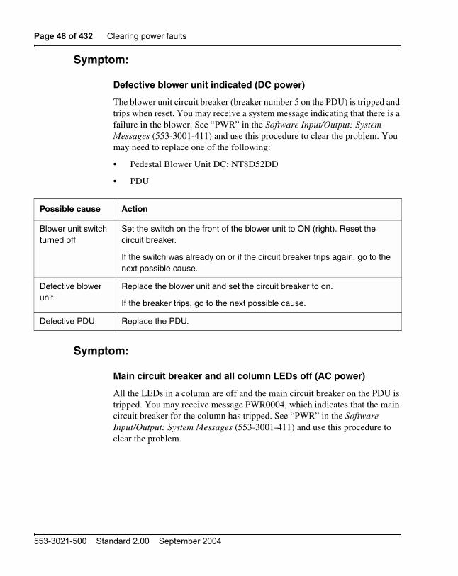
Defective blower unit indicated (DC power)
The blower unit circuit breaker (breaker number 5 on the PDU) is tripped and trips when reset. You may receive a system message indicating that there is a failure in the blower. See “PWR” in the Software Input/Output: System Messages (553-3001-411) and use this procedure to clear the problem. You may need to replace one of the following:
• Pedestal Blower Unit DC: NT8D52DD
• PDU
Symptom:
Main circuit breaker and all column LEDs off (AC power)
All the LEDs in a column are off and the main circuit breaker on the PDU is tripped. You may receive message PWR0004, which indicates that the main circuit breaker for the column has tripped. See “PWR” in the Software Input/Output: System Messages (553-3001-411) and use this procedure to clear the problem.
Possible cause Action
Blower unit switch turned off
Set the switch on the front of the blower unit to ON (right). Reset the circuit breaker.
If the switch was already on or if the circuit breaker trips again, go to the next possible cause.
Defective blower unit
Replace the blower unit and set the circuit breaker to on.
If the breaker trips, go to the next possible cause.
Defective PDU Replace the PDU.

Clearing power faults Page 49 of 432
Communication Server 1000M and Meridian 1 Large System Maintenance
High room temperature or a power surge can shut down the system. If all columns in a multi-column system are shut down, check for these external conditions. You may need to replace one of the following:
• Cooling Unit Filter Assembly: P0699798
• Air probe harness: NT8D46AM
• System monitor cables
• Thermostat harness: NT8D46AC
Possible cause Action
Short circuit or damage
Look for signs of damage (such as smoke, burnt contacts, or melted insulation) that may be caused by a short circuit or misplaced equipment.
If you do not find a problem of this type, go to the next possible cause.
Thermal overload Make sure nothing is blocking ventilation throughout the system. Allow the system to cool for a few minutes then reset the breaker.
If the breaker trips immediately, check the thermostat harness:
— Make sure the harness is securely connected to the module below it.
— Use an ohmmeter to check the connector pins for the harness; if there is an open circuit between pins 3 and 4 or between pins 5 and 6, replace the harness.
If the breakers do not trip immediately, check the air filter:
— If the filter is dirty and undamaged, clean the filter as described on page 237.
— If the filter is damaged in any way, replace the filter as described on page 239.
Page 50 of 432 Clearing power faults
553-3021-500 Standard 2.00 September 2004
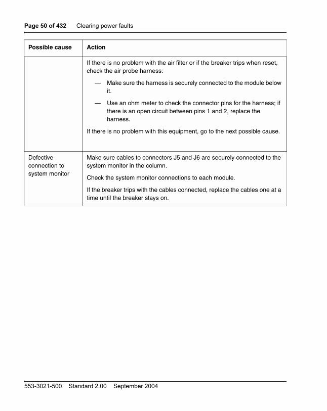
If there is no problem with the air filter or if the breaker trips when reset, check the air probe harness:
— Make sure the harness is securely connected to the module below it.
— Use an ohm meter to check the connector pins for the harness; if there is an open circuit between pins 1 and 2, replace the harness.
If there is no problem with this equipment, go to the next possible cause.
Defective connection to system monitor
Make sure cables to connectors J5 and J6 are securely connected to the system monitor in the column.
Check the system monitor connections to each module.
If the breaker trips with the cables connected, replace the cables one at a time until the breaker stays on.
Possible cause Action

Clearing power faults Page 51 of 432
Communication Server 1000M and Meridian 1 Large System Maintenance
Symptom:
Main circuit breaker on but all column LEDs off (AC power)
All the LEDs in the column are off but the main circuit breaker on the PDU is not tripped. Use this procedure to clear the problem. You may need to replace one of the following:
• PDU: NT8D53AB
• Main power cord
• UPS
Possible cause Action
Power cord not connected
If the power cord for the column is unplugged, plug it in.
If the power cord is already plugged in or if the column LEDs do not light when it is plugged in, go to the next possible cause.
WARNINGThe following tests are performed on a live power connection.
No power at outlet With a meter or test lamp, test for AC power at the outlet.
If there is no power at the outlet when AC power is supplied through a UPS unit, repair or replace the UPS following the manufacturer’s instructions.
If there is no power at the outlet when AC power is supplied through commercial service (not through a UPS), take the necessary steps to have the commercial power restored.
If there is power at the outlet, go to the next possible cause.
Defective power cord
With a meter or test lamp, test the field wiring connections in the PDU for AC power.
If there is no power, replace the power cord.
If there is power at the connections, go to the next possible cause.
Defective PDU Replace the PDU.

Page 52 of 432 Clearing power faults
553-3021-500 Standard 2.00 September 2004
Symptom:
Breaker off on MPDU (AC power)
A circuit breaker on a MPDU is tripped and trips when reset. The green LED will be off on the associated power supply:
• NT8D56AA single breaker MPDU: for NT8D29 CE Power Supply
• NT8D57AA dual breaker MPDU: for NT8D06 IPE Power Supply and NT8D21 Ringing Generator
You may receive a system message indicating the status of the breaker. See “PWR” in the Software Input/Output: System Messages (553-3001-411) and use this procedure to clear the problem.

Clearing power faults Page 53 of 432
Communication Server 1000M and Meridian 1 Large System Maintenance
Possible cause Action
Short circuit or damage
Look for signs of damage (such as smoke, burnt contacts, or melted insulation) that may be caused by a short circuit or misplaced equipment.
If you do not find a problem of this type, go to the next possible cause.
Defective module power supply (single breaker)
Unseat the associated power supply and reset the breaker.
If the breaker does not trip, replace the power supply.
If the breaker trips, replace the MPDU.
Defective module power supply (dual breaker)
If one circuit breaker is tripped on a dual MPDU:
Unseat the associated power supply (see Figure 6) then reset the breaker.
If the breaker does not trip, replace the power supply.
If the breaker trips, replace the MPDU.
If both circuit breakers are tripped:
Unseat both power supplies, then reset the breakers.
If either breaker or both breakers trip, replace the MPDU.
If the breakers do not trip, set them to OFF (down):
Reinsert one power supply then reset the associated breaker.
If the breaker trips, replace that power supply.
If the breaker does not trip, set the breaker to OFF and unseat that power supply.
Reinsert the other power supply, then reset the associated breaker.
If the breaker trips, replace that power supply.
Page 54 of 432 Clearing power faults
553-3021-500 Standard 2.00 September 2004
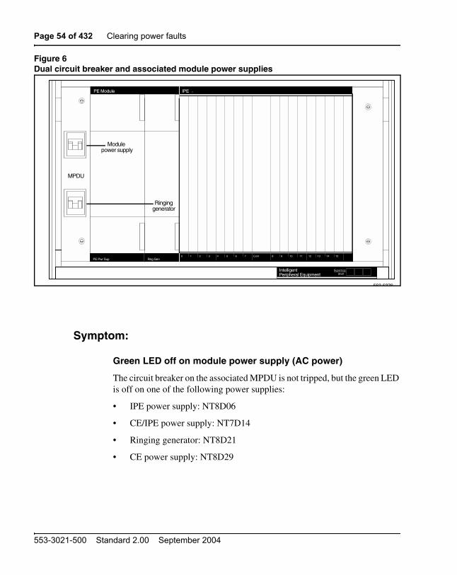
Figure 6Dual circuit breaker and associated module power supplies
Symptom:
Green LED off on module power supply (AC power)
The circuit breaker on the associated MPDU is not tripped, but the green LED is off on one of the following power supplies:
• IPE power supply: NT8D06
• CE/IPE power supply: NT7D14
• Ringing generator: NT8D21
• CE power supply: NT8D29
IntelligentPeripheral Equipment
SuperloopShelf
IPEPE Module
PE Pwr Sup Rng Gen0 2 3 4 5 6 7 Cont 9 11 12 13 151 8 14
553-5376
10
Module power supply
MPDU
Ringinggenerator

Clearing power faults Page 55 of 432
Communication Server 1000M and Meridian 1 Large System Maintenance
You may receive a system message indicating the status of the power supply. See “PWR” in the Software Input/Output: System Messages (553-3001-411) and use this procedure to clear the problem.
Possible cause Action
Disconnected power cable
Check the power cable connection between the power supply and the back of the MPDU.
If the cable is connected, check power cable connections to each module below the affected one (see Figure 7).
If all power cables are connected, go to the next possible cause.
Defective power supply
Set the circuit breaker on the associated MPDU off, then back on (see Figure 6 if there are dual circuit breakers).
If the LED on the power supply is still off, replace the power supply.
If you replace the power supply, the LED on the replacement should light and stay lit. If it does not, go to the next possible cause.
Defective MPDU Replace the MPDU.

Page 56 of 432 Clearing power faults
553-3021-500 Standard 2.00 September 2004
Figure 7AC power cabling in rear of column
553-3012
MODULE 1
MODULE 0
Main powerconnector tonext module
Main powerconnectorto pedestal
I/O safetypanel
Rear of the column
Main powerconnector tonext module
I/O safetypanel
Module power connectors
Module power connectors

Clearing power faults Page 57 of 432
Communication Server 1000M and Meridian 1 Large System Maintenance
Symptom:
Defective blower unit indicated (AC power)
The blower unit circuit breaker (located on the front of the unit) is tripped and trips when reset. You may receive a system message indicating that there is a failure in the blower. See “PWR” in the Software Input/Output: System Messages (553-3001-411) and use this procedure to clear the problem. You may need to replace one of the following:
• Blower unit: NT8D52AB
• PDU: NT8D53
Possible cause Action
Defective blower unit
Replace the blower unit and set the circuit breaker to ON (up).
If the breaker trips, go to the next possible cause.
Defective PDU Replace the PDU.

Page 58 of 432 Clearing power faults
553-3021-500 Standard 2.00 September 2004
Candeo power systemsCandeo power systems are based upon modular building blocks (rectifiers, System Manager, DC distribution, and battery connection modules) and designed to power -48 V DC applications. There are two types of Candeo systems: Large Candeo, which uses 50 A rectifiers and has a capacity of 1000 A, and Small Candeo (SP48300), which uses 30 A rectifiers and has a capacity of 300 A. The Candeo interfaces with the system through the Candeo's System Manager alarm output ports.
The Large Candeo System Manager produces a Major Alarm for the following faults:
• High voltage shut down (HVSD)
• High voltage (HV)
• Battery on discharge (BOD)
• Low voltage (LV)
• Low voltage disconnect (LVD)
• Alarm busy supply (ABSF)
• Internal fuse alarm (INT FA)
• Fuse alarm (FA)
• Rectifier fail alarm (RFA)
The Small Candeo (SP48300) System Manager produces a Major Alarm for the following faults:
• Battery fuse alarm
• High battery temperature
• High voltage shutdown (HVSD)
• Main AC fail
• Rectifier fail major (RFA major)
• Low voltage disconnect (LVD)
• High voltage (HV)
• Fuse alarm (FA)

Clearing power faults Page 59 of 432
Communication Server 1000M and Meridian 1 Large System Maintenance
• Priority low voltage disconnect
• AC input overvoltage
• Rectifier AC fail
• Remote shutdown
• System Manager SP fail
• Configuration fail
• Battery on discharge (BOD)
• Low voltage (LV)
• Very high battery temperature
For information on clearing alarms on the Candeo power systems, refer to the Candeo Power Systems User Guide (P0914425) and Candeo SP 48300 Power System AP6C55AA User Manual (P7000154).

Page 60 of 432 Clearing power faults
553-3021-500 Standard 2.00 September 2004

Page 61 of 432
Communication Server 1000M and Meridian 1 Large System Maintenance
72
Clearing common equipment faults
ContentsThis section contains information on the following topics:
Common equipment faults . . . . . . . . . . . . . . . . . . . . . . . . . . . . . . . . . . 61
Fault clearing procedures . . . . . . . . . . . . . . . . . . . . . . . . . . . . . . . . . . . 62
Common equipment faultsCommon equipment (CE) functions perform system control and switching. Common equipment can include:
• Bus Terminating Unit (BTU): provides logical termination to CPU and network buses
• Central Processing Unit (CPU): performs system call processing functions
• Call Processor (CP): performs system arithmetic and logic functions
• Data cartridge: allows access to software packages purchased
• Mass Storage Interface card (floppy disk interface card, mass storage interface card, or enhanced mass storage interface card): interface between the CPU and the mass storage unit
• Mass Storage Unit (floppy disk unit, multi drive unit, small system multi drive unit, or core multi disk unit): provides a backup for programs and data stored in system memory
• Read Only Memory (ROM) card: provides memory for the CPU on the NT6D66 Call Processor

Page 62 of 432 Clearing common equipment faults
553-3021-500 Standard 2.00 September 2004
• Serial Data Interface (SDI) card: provides ports between the CPU and external devices
• Core to Network Interface (CNI) card: links the CE bus with the three-port extender (3PE) card(s) in the network slots
• Three-Port Extender (3PE) card: extends CPU signals to the network, and between Core Network Interface (CNI) and the network.
Common equipment faults can disable the CPU or the mass storage unit and stop call processing. In addition, other types of equipment (such as network equipment) may not operate properly while there is a CE fault in the system.
Look up all system messages and maintenance display codes in the Software Input/Output: System Messages (553-3001-411) and follow the instructions given. If the fault does not clear, use the following procedures.Take any action indicated by the maintenance display codes. Continually observe and look up system messages as you perform the procedure.
Fault clearing proceduresThe following table lists common equipment fault indications. Refer to “How to clear faults” on page 27 for complete fault clearing process.
Indicator Possible indications
System messages BSD080, 085, 086, 103
CED messages
INI001, 002, 004, 005
IOD006, 007, 060, 061, 291–297
NWS030, 102, 103, 142
SYS messages
Visual indicators Major alarm on attendant consoles
Red LED lit on column top cap
Red LED lit on CE card of active CPU

Clearing common equipment faults Page 63 of 432
Communication Server 1000M and Meridian 1 Large System Maintenance
Symptom:
Fault indicated on a common equipment card
The red LED is lit or the display is indicating a fault on a common equipment card. The dual Core system will still be operating but may be limited to one CP. Make sure the normal/maintenance switch on both Call Processor cards is set to Norm.
For information on switch settings for the applicable Core cards, see Circuit Card: Description and Installation (553-3001-211). You may need to replace one of the following:
• CP card
• CP to CP cable: NTND11
Maintenance displays QPC580 CPU Interface
NT8D19 Memory/Peripheral Signaling
QPC584 Mass Storage Interface
NT9D34 Enhanced Mass Storage Interface
QPC742 Floppy Disk Interface
NTND01 ICM card
NTND10 CMA card
NT6D66, NT9D19, NT5D10 Call Processor
NT6D63 IOP card
NT5D61 IODU/C card
User reports Major alarm reported by attendant
WARNINGModule covers are not hinged; do not let go of the cover. Lift the cover away from the module and set it out of your work area.

Page 64 of 432 Clearing common equipment faults
553-3021-500 Standard 2.00 September 2004
• IODU/C card: NT5D61
• IOP card: NT6D63
• CNI card: NT6D65
• 3PE card: QPC441
• CBT card: NT6D6003

Clearing common equipment faults Page 65 of 432
Communication Server 1000M and Meridian 1 Large System Maintenance
cPCI Core/Network Card Cage AC/DC: NT4N46AA
Possible cause Action
Defective serial I/O ports
Check each SDI port by entering:
LD 37STAT TTY
If software is disabled, try to enable it (software disable, hardware disable, then try to reenable).
If the card will not enable, replace it.
If the CPU is still faulty, go to the next possible cause.
Defective IOP card Check the IOP card:
Reinstall the IOP card, test it, and enable it:
LD 137DIS IOPTEST IOPENL IOP****
If the CPU is still faulty, go to the next possible cause.

Page 66 of 432 Clearing common equipment faults
553-3021-500 Standard 2.00 September 2004
Defective CE card (lit LED)
Unseat the CP and CNI cards, then reinstall them. Make sure all cables are securely connected. If all cards do not recover, continue with this procedure.
If the display on the CP card shows a fault:
LD 135TEST CPU
If there is a problem with the test, CCED system messages will be generated.
If the LED is lit on some other CE card, check the CNI card, enter:
LD 135TEST CNI c s
where c represents the CPU 0 or 1 and s represents the card slot.
If the CPU is still faulty, replace the CE cables one at a time.
If CNI is faulty, disable the card before you out it.
If the CPU remains faulty, go to the next possible cause.
Defective backplane Replace the card cage assembly in the module.
To be able to replace the card cage, you must first switch the system to use the alternate CPU and then disable and remove all the cards in the card cage you wish to replace.
Defective serial I/O ports
Check each SDI port by entering:
LD 37STAT TTY
If software is disabled, try to enable it (software disable, hardware disable, then try to reenable).
If the card will not enable, replace it.
If the CPU is still faulty, go to the next possible cause.
Possible cause Action

Clearing common equipment faults Page 67 of 432
Communication Server 1000M and Meridian 1 Large System Maintenance
Defective IOP card Check the IOP card:
Reinstall the IOP card, test it, and enable it:
LD 137DIS IOPTEST IOPENL IOP****
If the CPU is still faulty, go to the next possible cause.
Defective CE card (lit LED)
Unseat the CP and CNI cards, then reinstall them. Make sure all cables are securely connected. If all cards do not recover, continue with this procedure.
If the display on the CP card shows a fault:
LD 135TEST CPU
If there is a problem with the test, CCED system messages will be generated.
If the LED is lit on some other CE card, check the CNI card, enter:
LD 135TEST CNI c s
where c represents the CPU 0 or 1 and s represents the card slot.
If the CPU is still faulty, replace the CE cables one at a time.
If CNI is faulty, disable the card before you out it.
If the CPU remains faulty, go to the next possible cause.
Possible cause Action

Page 68 of 432 Clearing common equipment faults
553-3021-500 Standard 2.00 September 2004
Symptom:
Floppy disk unit not operating
Note: There may be a lit LED on the Floppy Disk Unit (FDU). There may be a maintenance display code on the Floppy Disk Interface (FDI) card indicating a problem with the FDU. For information on switch settings, see Circuit Card: Description and Installation (553-3001-211). You may need to replace one of the following:
• Cable between FDU and FDI card
• Security Data cartridge: QMM42
• FDI card: QPC742
• FDU: NT8D68 or NTND15
Possible cause Action
Defective FDI card or data cartridge
Unseat the FDU and FDI card, then reinstall them. Make sure the cable between the FDU and FDI is securely connected. (In a dual CPU system, check both FDI cards.) If the FDU does not recover, continue with this procedure.
Check the FDI:
Make sure the data cartridge is securely attached.
Check switch settings; if necessary, correct the switch settings.
Try to enable the FDI (try to software disable, hardware disable, then reenable).
If you cannot load a program or the FDI is still disabled, replace it.
If necessary, replace the data cartridge.
If the FDU is still not operating, go to the next possible cause.
Defective FDU or cable
Replace the FDU. If it is still disabled, replace the cable between the FDU and FDI.

Clearing common equipment faults Page 69 of 432
Communication Server 1000M and Meridian 1 Large System Maintenance
Symptom:
IODU/C not operating
There may or may not be a lit LED on the front of the IODU/C. For more information on IODU/C, see the Communication Server 1000M and Meridian 1: Large System Upgrade Procedures (553-3021-258). For information on switch settings, see Circuit Card: Description and Installation (553-3001-211). You may need to replace one of the following:
• IODU/C: NT5D61
• cPCI Core/Network Card Cage AC/DC: NT4N46AA
Possible cause Action
Defective IODU/C (lit LED)
Unseat the IODU/C, then reinstall it. If the IODU/C does not recover, continue with this procedure.
Try to restore the hard drive from disks:
— Stat, enable, and test the CMDU part of the IODU/C card:
LD 137STAT CMDU xTEST CMDU xDIS CMDU XSYNCENL CMDU X
If the problem continues, a CIOD system message appears and the LED lights on the faceplate.
If you cannot load the program, replace the IODU/C:
— If you can load the program, test the port for the system terminal you were using.
— If the port is okay, test the cable to the system terminal.
— If the cable is okay, check the system terminal.
If the CMDU part of the IODU/C is still faulty, go to the next possible cause.

Page 70 of 432 Clearing common equipment faults
553-3021-500 Standard 2.00 September 2004
Defective IOP part of the IODU/C card
Check the IOP part of the IODU/C card:
— Reinstall the IODU/C card; test and enable the IOP part of the IODU/C card.
LD 137DIS IOPTEST IOPENL IOP
If the IODU/C is still faulty, go to the next possible cause.
Defective backplane connection to IODU/C (LED not lit)
Try to test the IODU/C by entering:
LD 137TEST CMDU x “x” represents the IODU/C card number 0 or 1
If the CMDU part of the IODU/C card is still faulty, replace the IODU/C card.
If the CMDU part of the IODU/C enables after it is moved, replace the card cage assembly in the module you took it from.
CD-ROM drive not operating
For redundant systems, remove the disk from the CD-ROM drive, place it in the CD-ROM drive of the other Core, and test operation.
If the CD-ROM drive is operational you may need to replace the IODU/C card with the faulty CD-ROM drive.
Possible cause Action
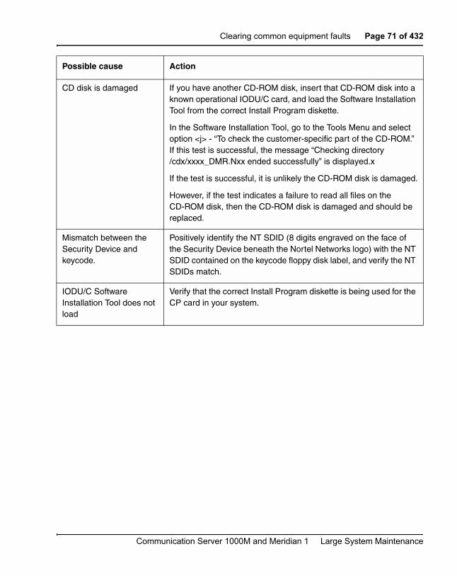
Clearing common equipment faults Page 71 of 432
Communication Server 1000M and Meridian 1 Large System Maintenance
CD disk is damaged If you have another CD-ROM disk, insert that CD-ROM disk into a known operational IODU/C card, and load the Software Installation Tool from the correct Install Program diskette.
In the Software Installation Tool, go to the Tools Menu and select option <j> - “To check the customer-specific part of the CD-ROM.” If this test is successful, the message “Checking directory /cdx/xxxx_DMR.Nxx ended successfully” is displayed.x
If the test is successful, it is unlikely the CD-ROM disk is damaged.
However, if the test indicates a failure to read all files on the CD-ROM disk, then the CD-ROM disk is damaged and should be replaced.
Mismatch between the Security Device and keycode.
Positively identify the NT SDID (8 digits engraved on the face of the Security Device beneath the Nortel Networks logo) with the NT SDID contained on the keycode floppy disk label, and verify the NT SDIDs match.
IODU/C Software Installation Tool does not load
Verify that the correct Install Program diskette is being used for the CP card in your system.
Possible cause Action

Page 72 of 432 Clearing common equipment faults
553-3021-500 Standard 2.00 September 2004

Page 73 of 432
Communication Server 1000M and Meridian 1 Large System Maintenance
98
Clearing network equipment faults
ContentsThis section contains information on the following topics:
Network equipment faults . . . . . . . . . . . . . . . . . . . . . . . . . . . . . . . . . . . 73
Fault clearing procedures . . . . . . . . . . . . . . . . . . . . . . . . . . . . . . . . . . . 74
Network equipment faultsNetwork equipment provides speech path switching and transmits and receives signaling messages from the CPU. Network equipment can include:
• conference/tone and digit switch (CONF/TDS) card: provides conference capability, all tones for the system, and multi frequency sender (MFS) functionality
• intergroup switch (IGS) card: provides speech path switching between network groups for Meridian 1 PBX 81C
• network card: provides digital switching for the system
• The NT8D04 Superloop Network Card provides the equivalent of four network loops. The NT1P61 Fiber Superloop Network card and the NT7R51 Local Carrier Interface card provide the equivalent of two network loops.
• peripheral signaling (PS) card: provides the signaling interface to the CPU and clocking

Page 74 of 432 Clearing network equipment faults
553-3021-500 Standard 2.00 September 2004
• The NTND02 Misc/SDI/Peripheral Signaling Card combines the functionality of peripheral signaling and SDI cards, as well as miscellaneous CPU functions.
• serial data interface (SDI) card: provides the interface from the CPU to an input/output (I/O) device
Network equipment faults can cause system initializations and disable conference capability or all terminal connections (such as trunks and telephones) on a loop. Defective network equipment can make functional peripheral equipment seem faulty.
Fault clearing proceduresManual continuity tests can be used to isolate superloop network card and IPE faults. For a description of manual continuity tests, see “Software maintenance tools” on page 197. See “LD 45” in the Software Input/Output: Maintenance (553-3001-511) for details on performing the tests.
Look up all system messages and maintenance display codes in the Software Input/Output: System Messages (553-3001-411) and follow the instructions given. Continually observe and look up system messages as you perform this procedure.
Replace equipment as described on page 239.
Table 10 lists common network equipment fault indications. Refer to “How to clear faults” on page 27 for complete fault clearing process.
WARNINGModule covers are not hinged; do not let go of the cover. Lift the cover away from the module and set it out of your work area.

Clearing network equipment faults Page 75 of 432
Communication Server 1000M and Meridian 1 Large System Maintenance
Symptom:
Disabled loop indicated by OVD message(NT1P61 Fiber Superloop Network Card)
An overload (OVD) system message indicates that a loop on an NT1P61 Fiber Superloop Network Card is disabled. All terminal connections on the loop are disabled. A red LED on the card may be lit or flashing. You may need to replace one of the following:
• Fiber Peripheral Controller card: NT1P62
Table 10Network equipment fault indicators
Indicator Possible indications
System messages BSD081, 101, 110, 111, 121, 130, 201–203, 205–209, 600, 602
CNF messages
DTA, DTC, DTI messages
ERR020, 120, 4060
INI003, 007–012
NWS101, 141, 201–204, 301, 401
OVD021, 022, 023, 031
TDS messages
XMI messages
Visual indicators Minor alarm on an attendant console
Red LEDs lit or flashing on cards
User reports Minor alarm reported by attendant
Users cannot transfer or conference
Users cannot dial out on 500/2500 telephones
No dial tone at all sets; no display on digital sets

Page 76 of 432 Clearing network equipment faults
553-3021-500 Standard 2.00 September 2004
• Fiber Superloop network card: NT1P61
• IPE card
• Cable between superloop network card and controller card

Clearing network equipment faults Page 77 of 432
Communication Server 1000M and Meridian 1 Large System Maintenance
Possible cause Action
Defective superloop network card
Hardware disable, then reenable, the superloop network card to initiate a self-test or executing the XNTT loop command. If the test fails, check the card status.
Check the status of the Fiber Superloop Network card:
LD 30STAT loop “loop” represents the loop number.
Check the display and take steps to resolve the problem indicated is the status report.
If you receive an OVD message, replace the superloop network card.
If the card is disabled, enable it by executing the ENLL loop command. If the response is UNEQ, install the card correctly and observe self-test.
Defective controller card
Perform the Fiber Peripheral Controller card self-test:
DSXP x “x” represents the controller number.
If the test passed, enable the card by executing:
ENXP x “x” represents the controller number.
If the test failed, check the maintenance display codes on the controller card and wait for an OVD message. In the OVD message is received, replace the card.
If there is no OVD message, go to the next possible cause.
Defective IPE card Reinsert the IPE cards one at a time. Wait for an OVD message after each card is inserted.
If the red LED lights when a card is inserted, software disable the card, then try to reenable it. If it will not enable, replace the card.
If you receive an OVD message when one of the IPE cards is inserted, replace that card.
If there is no OVD message as you insert the cards, go to the next possible cause.

Page 78 of 432 Clearing network equipment faults
553-3021-500 Standard 2.00 September 2004
Symptom:
Disabled loop indicated by OVD message(NT7R51 Local Carrier Interface Card)
An overload (OVD) system message indicates that a loop on an NT7R51 Local Carrier Interface Card is disabled. All terminal connections on the loop are disabled. A red LED on the card may be lit or flashing. You may need to replace one of the following:
• Remote Carrier Interface card: NT7R52
• Local Carrier Interface card: NT7R51
• IPE card
• Cable between superloop network card and controller card
Defective Fiber-optic span
To check the Fiber-optic span, perform loopback test across the span.
Load LD 45 and execute the XCON 6 test with Fiber Superloop Network card as the generator and detector with span looped at the Fiber Peripheral Controller card at the Fiber Remote IPE.
Check the test results and proceed accordingly.
Defective terminal equipment
Check terminal equipment (such as attendant consoles and telephones) on the disabled loop.
If you find defective terminal equipment, see the appropriate chapter (such as “Clearing attendant console faults” on page 121) to fix the fault.
Possible cause Action

Clearing network equipment faults Page 79 of 432
Communication Server 1000M and Meridian 1 Large System Maintenance
Possible cause Action
Defective Local Carrier Interface card
Hardware disable, then reenable, the superloop network card to initiate a self-test. If the test fails, replace the card. If the test passes, follow the procedure below.
Check the status of the Local Carrier Interface card:
LD 32STAT sl “sl” represents the loop number.
Check the display and take steps to resolve the problem indicated is the status report.
If you receive an OVD message, replace the superloop network card.
If the card is disabled, enable it by executing the ENLL sl command. If the response is UNEQ, install the card correctly and observe self-test.
Defective Remote Carrier Interface card
Unseat all cards on the IPE shelf except the Remote Carrier Interface card. Unseat and seat the Remote Carrier Interface card to start self-test. Observe self-test:
If the test passed, enable the card by executing:
ENXP x “x” represents the controller number.
If the test failed, check the maintenance display codes on the card faceplate and wait for an OVD message. In the OVD message is received, replace the card.
If there is no OVD message, go to the next possible cause.

Page 80 of 432 Clearing network equipment faults
553-3021-500 Standard 2.00 September 2004
Defective IPE card
Reinsert the IPE cards one at a time. Wait for an OVD message after each card is inserted.
If the red LED lights when a card is inserted, software disable the card, then try to reenable it. If it will not enable, replace the card.
If you receive an OVD message when one of the IPE cards is inserted, replace that card.
If there is no OVD message as you insert the cards, go to the next possible cause.
Defective cable To check the carrier span, perform loopback test across the span.
Load LD 45 and execute the XCON 6 test with Local Carrier Interface card as the generator and detector with span looped at the Remote Carrier Interface card at the Carrier Remote IPE.
Check the test results and proceed accordingly.
If there is no OVD message, go to the next possible cause.
Defective terminal equipment
Check terminal equipment (such as attendant consoles and telephones) on the disabled loop.
If you find defective terminal equipment, see the appropriate chapter (such as “Clearing attendant console faults” on page 121) to fix the fault.
Defective Local Carrier Interface card
Hardware disable, then reenable, the superloop network card to initiate a self-test. If the test fails, replace the card. If the test passes, follow the procedure below.
Check the status of the Local Carrier Interface card:
LD 32STAT sl “sl” represents the loop number.
Check the display and take steps to resolve the problem indicated is the status report.
If you receive an OVD message, replace the superloop network card.
If the card is disabled, enable it by executing the ENLL sl command. If the response is UNEQ, install the card correctly and observe self-test.
Possible cause Action

Clearing network equipment faults Page 81 of 432
Communication Server 1000M and Meridian 1 Large System Maintenance
Defective Remote Carrier Interface card
Unseat all cards on the IPE shelf except the Remote Carrier Interface card. Unseat and seat the Remote Carrier Interface card to start self-test. Observe self-test:
If the test passed, enable the card by executing:
ENXP x “x” represents the controller number.
If the test failed, check the maintenance display codes on the card faceplate and wait for an OVD message. In the OVD message is received, replace the card.
If there is no OVD message, go to the next possible cause.
Defective IPE card
Reinsert the IPE cards one at a time. Wait for an OVD message after each card is inserted.
If the red LED lights when a card is inserted, software disable the card, then try to reenable it. If it will not enable, replace the card.
If you receive an OVD message when one of the IPE cards is inserted, replace that card.
If there is no OVD message as you insert the cards, go to the next possible cause.
Defective cable To check the carrier span, perform loopback test across the span.
Load LD 45 and execute the XCON 6 test with Local Carrier Interface card as the generator and detector with span looped at the Remote Carrier Interface card at the Carrier Remote IPE.
Check the test results and proceed accordingly.
If there is no OVD message, go to the next possible cause.
Defective terminal equipment
Check terminal equipment (such as attendant consoles and telephones) on the disabled loop.
If you find defective terminal equipment, see the appropriate chapter (such as “Clearing attendant console faults” on page 121) to fix the fault.
Possible cause Action

Page 82 of 432 Clearing network equipment faults
553-3021-500 Standard 2.00 September 2004
Symptom:
Disabled loop indicated by OVD message(NT8D04 Superloop Network Card)
An overload (OVD) system message indicates that a loop on an NT8D04 Superloop Network Card is disabled. All terminal connections on the loop are disabled. A red LED on the card may be lit or flashing. You may need to replace one of the following:
• Controller card: NT8D01
• Superloop network card: NT8D04
• IPE card
• Cable between superloop network card and controller card
Possible cause Action
Defective superloop network card
Hardware disable, then reenable, the superloop network card to initiate a self-test. If the test fails, replace the card. If the test passes, follow the procedure below.
Disconnect the loop cable(s) to the superloop network card. Enable and test each loop on the card by entering:
LD 32ENLL loop “loop” represents the loop number.
Wait for an OVD message.
If you receive an OVD message, replace the superloop network card.
If there is no OVD message, go to the next possible cause.

Clearing network equipment faults Page 83 of 432
Communication Server 1000M and Meridian 1 Large System Maintenance
Defective controller card
Unseat all cards on the IPE shelf except the controller card. Reconnect the loop cable to the controller card and enable the card by entering:
ENXP x “x” represents the controller number.
Note: If more than one shelf is involved, follow this and subsequent procedures one at a time for each controller card.
Check the maintenance display codes on the controller card and wait for an OVD message.
If you receive an OVD message, unseat and reinstall the controller card to initiate a self-test. If the test fails, replace the card and reinsert cards on the IPE shelf.
If there is no OVD message, go to the next possible cause.
Defective IPE card Reinsert the IPE cards one at a time. Wait for an OVD message after each card is inserted.
If the red LED lights when a card is inserted, software disable the card, then try to reenable it. If it will not enable, replace the card.
If you receive an OVD message when one of the IPE cards is inserted, replace that card.
If there is no OVD message as you insert the cards, go to the next possible cause.
Defective cable Disconnect the loop cable at the controller card. (If there is more than one loop cables, disconnect them one at a time and follow the procedure below for each cable.)
Reconnect the cable(s) to the superloop network card and wait for an OVD message.
If you receive an OVD message, replace the cable.
If there is no OVD message, go to the next possible cause.
Defective terminal equipment
Check terminal equipment (such as attendant consoles and telephones) on the disabled loop.
If you find defective terminal equipment, see the appropriate chapter (such as “Clearing attendant console faults” on page 121) to fix the fault.
Possible cause Action
Page 84 of 432 Clearing network equipment faults
553-3021-500 Standard 2.00 September 2004
Symptom:
Loop disabled without OVD message(NT8D04 Superloop Network Card)
There is probably a system message indicating the loop or loops on this card are defective or disabled, but there is no overload (OVD) message indicating the card is disabled. The LED on the faceplate may be lit or flashing. You may need to replace one of the following:
• Controller card: NT8D01
• Superloop network card: NT8D04
• IPE card
• Cable between superloop network card and controller card

Clearing network equipment faults Page 85 of 432
Communication Server 1000M and Meridian 1 Large System Maintenance
Possible cause Action
Defective superloop network card
Hardware disable, then reenable, the superloop network card to initiate a self-test. If the test fails, replace the card. If the test passes, follow the procedure below.
Disconnect the loop cable(s) to the superloop network card. Try to enable each loop on the card by entering:
LD 30ENLL loop “loop” represents the loop number.
Test each loop by entering:
LOOP loop
If you receive an OVD message at this point, replace the superloop network card.
If there is no OVD message and the loops will not enable, go to the next possible cause.
Defective controller card
Unseat all cards on the IPE shelf except the controller card. Reconnect the loop cable to the controller card and enable the controller card by entering:
LD 32ENXP x “x” represents the controller number.
Note: If more than one shelf is involved, follow this and subsequent procedures one at a time for each controller card.
Check the maintenance display codes on the controller card.
If you receive an OVD message at this point, unseat and reinstall the controller card to initiate a self-test. If the test fails, replace the card. Reinsert cards on the IPE shelf.
If there is no OVD message and the loops will not enable, go to the next possible cause.

Page 86 of 432 Clearing network equipment faults
553-3021-500 Standard 2.00 September 2004
Symptom:
Disabled loop indicated by OVD message(QPC414 Network Card)
An overload (OVD) system message indicates that a loop on a QPC414 Network Card is disabled. All terminal connections on the loop are disabled. A red LED on the card may be lit. For information on switch settings, see Circuit Card: Description and Installation (553-3001-211). You may need to replace one of the following:
• Dual loop peripheral buffer (DLB) card: QPC659
• Network card: QPC414
Defective IPE card Reinsert the IPE cards one at a time.
If the red LED lights when a card is inserted, software disable the card, then try to reenable it. If it will not enable, replace the card.
If you receive an OVD message when one of the IPE cards is inserted, replace that card.
If no LEDs light and there is no OVD message as you reinsert the cards, go to the next possible cause.
Defective cable Disconnect the loop cable at the controller card. (If there is more than one cable, disconnect them one at a time and follow the procedure below for each cable.)
Reconnect the cable(s) to the superloop network card.
If you receive an OVD message at this point replace the cable.
If there is no OVD message and the loops will not enable, go to the next possible cause.
Defective terminal equipment
Check terminal equipment (such as attendant consoles and telephones) on the disabled loop.
If you find defective terminal equipment, see the appropriate chapter (such as “Clearing attendant console faults” on page 121) to fix the fault.
Possible cause Action

Clearing network equipment faults Page 87 of 432
Communication Server 1000M and Meridian 1 Large System Maintenance
• IPE card
• Cable between network card and DLB card
Possible cause Action
Defective network card
Disconnect the loop cable(s) to the network card. Enable and test each loop on the network card by entering:
LD 30ENLL loop “loop” represents the loop number.
Test each loop by entering:
LOOP loop
Wait for an OVD message.
If you receive an OVD message, replace the network card.
If there is no OVD message, go to the next possible cause.
Defective DLB card
Unseat all cards on the IPE shelf except the DLB card (if there are two shelves on the loop, disconnect the cable to connector LPY):
— Reconnect the loop cable to the DLB card.
— If you receive an OVD message, replace the DLB card and reinsert cards on the IPE shelf.
If there is no OVD message:
— Check switch settings on the DLB card; if necessary, correct the switch settings.
— If there are two shelves on the loop, go to the next possible cause.
— If there is one shelf on the loop, go to “Disabled peripheral equipment card” on page 108

Page 88 of 432 Clearing network equipment faults
553-3021-500 Standard 2.00 September 2004
Defective DLB card on second shelf (if two shelves are on the loop)
Unseat all cards on the second shelf except the DLB card. Reconnect the inter-shelf cable to the DLB card and wait for an OVD message.
If there is an OVD message, replace the DLB card and reinsert cards on the IPE shelf.
If there is no OVD message, go to the next possible cause.
Defective NT5K10 DLB card
In Dual Loop Mode
— Unseat 4 IPE cards pertaining to the defective loop or
In Single Loop Mode
— Unseat 8 IPE cards pertaining to the defective loop.
Wait for the OVD message.
If there is no OVD message, go to the defective IPE card.
If you receive an OVD message, remove the backplane access plate at the back of the EEPE shelf and replace the Dual Loop Peripheral Buffer Card.
Reinsert the IPE cards on the shelf.
Replace the backplane access plate.
Defective IPE card Reinsert the IPE cards one at a time. (If there are two shelves on the loop, follow this and subsequent procedures one at a time for each shelf.) Wait for an OVD message after each card is inserted.
If the LED lights when a card is inserted, software disable the card, then try to reenable it. If it will not enable, replace the card.
If you receive an OVD message when one of the IPE cards is inserted, replace that card.
If there is no OVD message as you reinsert the cards, go to the next possible cause.
Possible cause Action

Clearing network equipment faults Page 89 of 432
Communication Server 1000M and Meridian 1 Large System Maintenance
Symptom:
Loop disabled without OVD message(QPC414 Network Card)
There is probably a system message indicating that the loop or loops on this card are defective or disabled, but there is no overload (OVD) message indicating the card is disabled. The LED on the faceplate may be lit. For information on switch settings, see Circuit Card: Description and Installation (553-3001-211). You may need to replace one of the following:
• Dual loop peripheral buffer (DLB) card: QPC659
Defective cable between network and DLB cards
For the EEPE shelf only: remove the backplane access plate at the back of the module.
Disconnect the loop cable at the DLB card.
Reconnect the cable(s) to the network card and wait for an OVD message.
If you receive an OVD message, replace the cable.
If there is no OVD message, go to the next possible cause.
For the EEPE shelf only: replace the backplane access plate.
Defective cable between shelves (if two shelves are on the loop)
Disconnect the inter-shelf cable to connector LPX on the second shelf DLB card.
Reconnect the cable to connector LPY on the first shelf DLB card and wait for an OVD message.
If you receive an OVD message, replace the inter-shelf cable. Reinsert cards on the IPE shelf.
If there is no OVD message, go to the next possible cause.
Defective terminal equipment
Check terminal equipment (such as attendant consoles and telephones) on the disabled loop.
If you find defective terminal equipment, see the appropriate chapter (such as “Clearing attendant console faults” on page 121) to fix the fault.
Possible cause Action

Page 90 of 432 Clearing network equipment faults
553-3021-500 Standard 2.00 September 2004
• Network card: QPC414
• IPE card
• Cable between network card and DLB card
Possible cause Action
Defective network card
Test the loops on the card by entering:
LD 30LOOP loop “loop” represents the loop number.
Try to enable the loops by entering:
ENLL loop
Wait for an OVD message.
If you receive an OVD message at this point, replace the network card.
If there is no OVD message and the loops will not enable, go to the next possible cause.
Defective DLB card
Unseat all cards on the IPE shelf except the DLB card (if there are two shelves on the loop, disconnect the cable to connector LPY):
— Reconnect the loop cable to the DLB card.
— If you receive an OVD message at this point, replace the peripheral buffer card and reinsert cards on the IPE shelf.
If there is no OVD message and the loops will not enable:
— Check switch settings on the DLB card; if necessary, correct the switch settings.
— If there are two shelves on the loop, go to the next possible cause.
— If there is one shelf on the loop, go to “Disabled peripheral equipment card” on page 108.
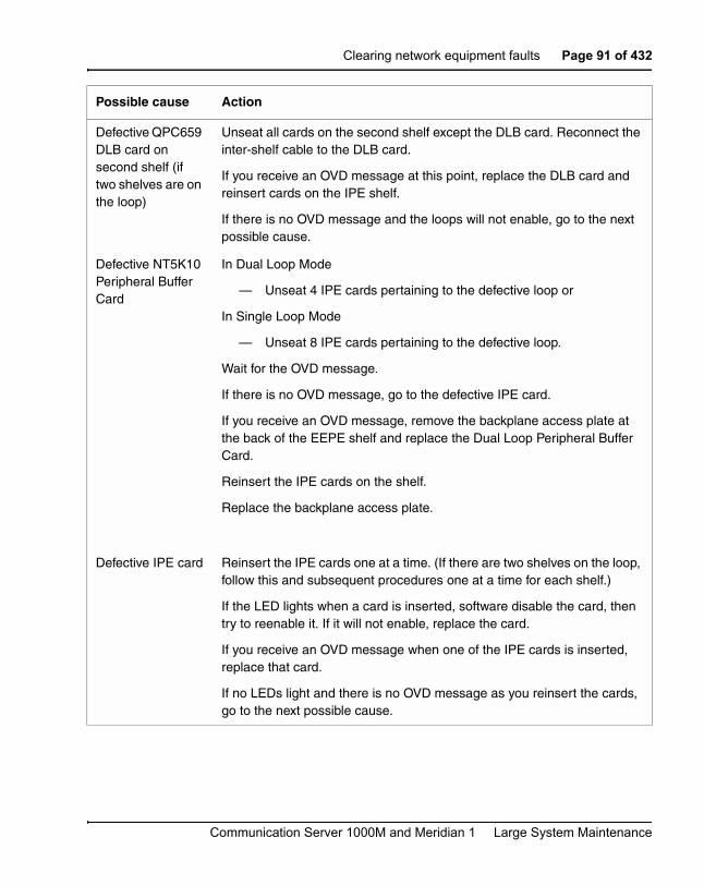
Clearing network equipment faults Page 91 of 432
Communication Server 1000M and Meridian 1 Large System Maintenance
Defective QPC659 DLB card on second shelf (if two shelves are on the loop)
Unseat all cards on the second shelf except the DLB card. Reconnect the inter-shelf cable to the DLB card.
If you receive an OVD message at this point, replace the DLB card and reinsert cards on the IPE shelf.
If there is no OVD message and the loops will not enable, go to the next possible cause.
Defective NT5K10 Peripheral Buffer Card
In Dual Loop Mode
— Unseat 4 IPE cards pertaining to the defective loop or
In Single Loop Mode
— Unseat 8 IPE cards pertaining to the defective loop.
Wait for the OVD message.
If there is no OVD message, go to the defective IPE card.
If you receive an OVD message, remove the backplane access plate at the back of the EEPE shelf and replace the Dual Loop Peripheral Buffer Card.
Reinsert the IPE cards on the shelf.
Replace the backplane access plate.
Defective IPE card Reinsert the IPE cards one at a time. (If there are two shelves on the loop, follow this and subsequent procedures one at a time for each shelf.)
If the LED lights when a card is inserted, software disable the card, then try to reenable it. If it will not enable, replace the card.
If you receive an OVD message when one of the IPE cards is inserted, replace that card.
If no LEDs light and there is no OVD message as you reinsert the cards, go to the next possible cause.
Possible cause Action

Page 92 of 432 Clearing network equipment faults
553-3021-500 Standard 2.00 September 2004
Symptom:
Disabled peripheral signaling card indicated by OVD message
There is an overload (OVD) system message indicating that a peripheral signaling card is disabled. The LED on the faceplate may be lit. You may need to replace one of the following:
• Superloop network card or network card: NT8D04, QPC414
• PS card: QPC43R
Defective cable between network and DLB cards
For EEPE shelf only: remove the backplane access plate at the rear of the module.
Disconnect the loop cable at the DLB card.
Reconnect the cable(s) to the network card.
If you receive an OVD message at this point, replace the cable.
If there is no OVD message and the loops will not enable, go to the next possible cause.
For EEPE shelf only: remove the backplane access plate at the rear of the module.
Defective cable between shelves (if two shelves on the loop)
Disconnect the inter-shelf cable to connector LPX on the second shelf DLB card.
Reconnect the cable to connector LPY on the first shelf DLB card.
If you receive an OVD message at this point, replace the inter-shelf cable. Reinsert cards on the IPE shelf.
If there is no OVD message and the loops will not enable, go to the next possible cause.
Defective terminal equipment
Check terminal equipment (such as attendant consoles and telephones) on the disabled loop.
If you find defective terminal equipment, see the appropriate chapter (such as “Clearing attendant console faults” on page 121) to fix the fault.
Possible cause Action

Clearing network equipment faults Page 93 of 432
Communication Server 1000M and Meridian 1 Large System Maintenance
• Clock controller: QPC471
• D-channel handler interface card: QPC757
Symptom:
Peripheral signaling card disabled without OVD message
The peripheral signaling card is disabled on one shelf. The LED on its faceplate may be lit. There is no overload (OVD) message indicating a fault with this card. You may need to replace one of the following:
• Superloop network card or network card: NT8D04, QPC414
• PS card: QPC43R
• Clock controller: QPC471
• D-channel handler interface card: QPC757
Possible cause Action
Defective PS card Unseat all network cards associated with the PS card.
Enable the PS card by entering:
LD 32ENPS x “x” represents the PS card number.
Wait for an OVD message.
If you receive an OVD message, replace the PS card.
If there is no OVD message, go to the next possible cause.
Defective network card
Reinsert network cards one at a time.
Wait for an OVD message after each card is inserted.
If you receive an OVD message when one of the cards is inserted, replace that card.
Reenable the PS card by entering:
LD 32ENPS x
If you do not receive an OVD message, go to the next possible cause.
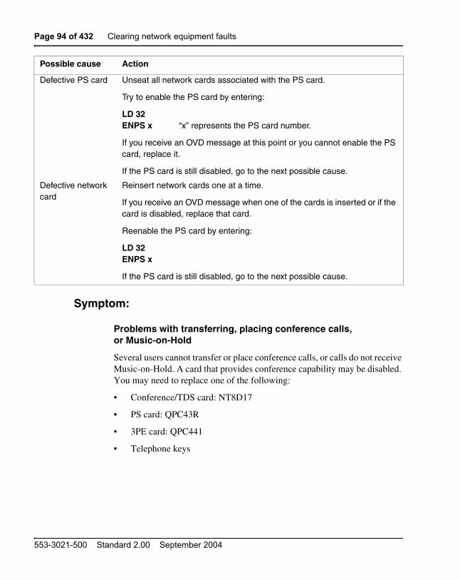
Page 94 of 432 Clearing network equipment faults
553-3021-500 Standard 2.00 September 2004
Symptom:
Problems with transferring, placing conference calls,or Music-on-Hold
Several users cannot transfer or place conference calls, or calls do not receive Music-on-Hold. A card that provides conference capability may be disabled. You may need to replace one of the following:
• Conference/TDS card: NT8D17
• PS card: QPC43R
• 3PE card: QPC441
• Telephone keys
Possible cause Action
Defective PS card Unseat all network cards associated with the PS card.
Try to enable the PS card by entering:
LD 32ENPS x “x” represents the PS card number.
If you receive an OVD message at this point or you cannot enable the PS card, replace it.
If the PS card is still disabled, go to the next possible cause.
Defective network card
Reinsert network cards one at a time.
If you receive an OVD message when one of the cards is inserted or if the card is disabled, replace that card.
Reenable the PS card by entering:
LD 32ENPS x
If the PS card is still disabled, go to the next possible cause.

Clearing network equipment faults Page 95 of 432
Communication Server 1000M and Meridian 1 Large System Maintenance
Possible cause Action
Defective conference/TDS card
If there are no messages indicating a fault on any conference loop, test each conference loop in the system by entering:
LD 38CNFC loop “loop” represents the conference loop number.
Note: See the Software Input/Output: Maintenance (553-3001-511) for other tests.
If the conference loop is disabled, try to enable it by entering:
LD 38ENLX loop “loop” represents the Conference loop, which is the odd
loop of the Conference/TDS loop pair.
Note: You must enable the card with the command ENLX. Enabling the loops with the command ENLL does not enable the hardware.
If a fault is indicated on a conference loop, replace the conference/TDS card identified.
If no faults are detected on any conference loop, go to the next possible cause.
Defective card on Network shelf
One at a time, replace the following cards until the fault clears:
— 3PE card
— PS card
If there is still a Conference problem, go to the next possible cause.
Defective telephone keys
Check the keys on any telephone with this problem. See the following Nortel Networks Publications:
— Software Input/Output: Maintenance (553-3001-511)—LD 31 tests
— Telephones and Consoles: Description, Installation, and Operation (553-3001-367)
Excessive traffic in the system
Additional conference/TDS cards may be required to handle the traffic in the system. See Traffic Measurement: Formats and Output (553-3001-450).
Page 96 of 432 Clearing network equipment faults
553-3021-500 Standard 2.00 September 2004
Symptom:
Problems placing calls on 2500 telephones and some trunks
Several users of 2500 telephones report trouble placing calls. Other users may report trouble dialing on certain trunks. A digitone receiver or a card that provides tone and digit switch capability may be disabled. You may need to replace one of the following:
• Tone Detector Card: QPC422
• Conference/TDS card: NT8D17
• DTR card: NT8D16
• Network/DTR card: NT8D18

Clearing network equipment faults Page 97 of 432
Communication Server 1000M and Meridian 1 Large System Maintenance
Possible cause Action
Defective digitone receiver
Check for disabled digitone receiver TNs by entering:
LD 34STAT
If any are disabled, try to enable them by entering:
ENLR l s c u “l s c u” represents loop, shelf, card, and unit numbers.
Test the digitone receiver by entering:
DTR l s c u
If the digitone receiver fails the test, replace it.
If the digitone receiver passes the test, go to the next possible cause.
Defective conference/TDS card
Test Tone and Digit Switch loops by entering:
LD 34TDS loop “loop” represents the loop number.
If the conference loop is disabled, try to enable it by entering:
ENLX loop “loop” represents the TDS/MFS loop, which is the even loop of the Conference/TDS loop pair).
Note: You must enable the card with the command ENLX. Enabling the loops with the command ENLL does not enable the hardware.
If a fault is indicated on a conference loop, replace the conference/TDS card identified.
If no faults are detected on any conference loop, go to the next possible cause.
Excessive traffic in the system
Additional digitone receivers or conference/TDS cards may be required to handle the traffic in the system. See Traffic Measurement: Formats and Output (553-3001-450).
Page 98 of 432 Clearing network equipment faults
553-3021-500 Standard 2.00 September 2004

Page 99 of 432
Communication Server 1000M and Meridian 1 Large System Maintenance
112
Clearing peripheral equipment faults
ContentsThis section contains information on the following topics:
Peripheral equipment faults. . . . . . . . . . . . . . . . . . . . . . . . . . . . . . . . . . 99
Fault clearing procedures . . . . . . . . . . . . . . . . . . . . . . . . . . . . . . . . . . . 100
Peripheral equipment faultsIntelligent Peripheral Equipment (IPE) provides the interface between network equipment switching and terminal equipment (such as trunks, telephones, data sets, and attendant consoles). Peripheral equipment faults can disable network and terminal equipment.
Note: For fault clearing purposes, the general term “peripheral equipment” includes intelligent peripheral equipment (IPE). When there are differences, IPE is specified.
CAUTIONNT6D71 fuse replacement F1 through F16.
For continued protection against risk of fire, replace the fuse only with a fuse of the same type and rating (125 V, 1.0 A).

Page 100 of 432 Clearing peripheral equipment faults
553-3021-500 Standard 2.00 September 2004
Fault clearing proceduresThe following table lists common peripheral equipment fault indications (many other system messages may be generated). Refer to “How to clear faults” on page 27 for complete fault clearing process.
Symptom:
Red LED lit on Fiber Peripheral Controller card
The red LED is lit on the controller card. Red LEDs on IPE cards on the same shelf may be lit. You may need to replace one of the following:
• Fiber Peripheral Controller card: NT1P62
• IPE card
• IPE card cage: NT8D3703

Clearing peripheral equipment faults Page 101 of 432
Communication Server 1000M and Meridian 1 Large System Maintenance
Possible cause Action
Defective Fiber peripheral controller card
Perform the Fiber controller card self-test by executing the DSXP x command for LD 32 to disable the card.
Execute the XPCT x command to initiate self-test.
— The maintenance display on the card shows the code for each test running (see “HEX” in the Software Input/Output: Maintenance (553-3001-511)If the tests complete successfully, the display continuously flashes.
— If the card continually fails a test, the code for that test is steadily displayed.
If the test fails, replace the card.
If the test passes but the card is still disabled, enable the card:
ENXP x “x” represents the controller number.
If the test fails, go to the next possible cause.
Defective IPE card Unseat all the cards in the shelf associated with the controller card:
— If the red LED on the controller card turns off, the fault is in one of the unseated cards.
— Reinsert the cards one at a time.
— When the controller card LED turns on again, replace the last card you inserted.
If the red LED on the controller card does not turn off when the IPE cards are unseated, reinstall the cards and go to the next possible cause.
Defective cable Test all cables to the controller card.
If you find a defective cable, replace it.
If there is no problem with the cables, go to the next possible cause.
Defective backplane
Replace the card cage assembly in the module.
Page 102 of 432 Clearing peripheral equipment faults
553-3021-500 Standard 2.00 September 2004
Symptom:
Red LED lit on Remote Carrier Interface card
The red LED is lit on only one controller card. Red LEDs on IPE cards on the same shelf may be lit. You may need to replace one of the following:
• Remote Carrier Interface card: NT7R52
• IPE card
• IPE card cage: NT8D3703

Clearing peripheral equipment faults Page 103 of 432
Communication Server 1000M and Meridian 1 Large System Maintenance
Possible cause Action
Defective Remote Carrier Interface card
Perform the remote carrier interface card self-test by removing and reinstalling the card.
Observe the self-test:
— The maintenance display on the card shows the code for each test running (see “HEX” in theSoftware Input/Output: Maintenance (553-3001-511)If the tests complete successfully, the display continuously flashes.
— If the card continually fails a test, the code for that test is steadily displayed.
If the test fails, replace the card.
If the test passes but the card is still disabled, enable the card:
ENLL sl “sl” represents the card number.
If the test fails, go to the next possible cause.
Defective IPE card Unseat all the cards in the shelf associated with the controller card:
— If the red LED on the controller card turns off, the fault is in one of the unseated cards.
— Reinsert the cards one at a time.
— When the controller card LED turns on again, replace the last card you inserted.
If the red LED on the controller card does not turn off when the IPE cards are unseated, reinstall the cards and go to the next possible cause.
Defective cable Test all cables to the controller card.
If you find a defective cable, replace it.
If there is no problem with the cables, go to the next possible cause.
Defective backplane
Replace the card cage assembly in the module.

Page 104 of 432 Clearing peripheral equipment faults
553-3021-500 Standard 2.00 September 2004
Symptom:
Red LED lit on Peripheral Controller card
The red LED is lit on only one controller card. Red LEDs on IPE cards on the same shelf may be lit. You may need to replace one of the following:
• Controller card: NT8D01BC, NT8D01AC, NT8D01AD
• IPE card
• IPE card cage: NT8D3703

Clearing peripheral equipment faults Page 105 of 432
Communication Server 1000M and Meridian 1 Large System Maintenance
Possible cause Action
Defective controller card
Remove, then, reinstall the controller card to initiate a self-test:
— The maintenance display on the card shows the code for each test running (see “HEX” in the Software Input/Output: Maintenance (553-3001-511)
— If the tests complete successfully, the display continuously flashes.
— If the card continually fails a test, the code for that test is steadily displayed.
If the test fails, replace the card.
If the test passes but the card is still disabled, test the loop by entering:
LD 30LOOP loop “loop” represents the loop number.
If the test fails, go to the next possible cause.
Defective IPE card Unseat all the cards in the shelf associated with the controller card:
— If the red LED on the controller card turns off, the fault is in one of the unseated cards.
— Reinsert the cards one at a time.
— When the controller card LED turns on again, replace the last card you inserted.
If the red LED on the controller card does not turn off when the IPE cards are unseated, reinstall the cards and go to the next possible cause.
Defective cable Test all cables to the controller card.
If you find a defective cable, replace it.
If there is no problem with the cables, go to the next possible cause.
Defective backplane
Replace the card cage assembly in the module.
Page 106 of 432 Clearing peripheral equipment faults
553-3021-500 Standard 2.00 September 2004
Symptom:
Red LED lit on dual loop peripheral buffer card
The red LED is lit on only one dual loop peripheral buffer card. Red LEDs on IPE cards on the same shelf may be lit. For information on switch settings, see Circuit Card: Description and Installation (553-3001-211). You may need to replace one of the following:
• Dual loop peripheral buffer (DLB) card: QPC659 or NT5K10
• Existing Peripheral Equipment Power Supply (EPEPS): NT5K12
• Cable between the Network Superloop card and the Enhanced Dual Loop Peripheral Buffer Card
• IPE card
• IPE card cage NT8D1303 or NT5K1106

Clearing peripheral equipment faults Page 107 of 432
Communication Server 1000M and Meridian 1 Large System Maintenance
Possible cause Action
Defective QPC659M DLB card
Test the shelf by entering:
LD 30LOOP l s “l s” represents loop and shelf numbers.
Note: If two loops are assigned to the shelf, be sure to test both.
If a defective DLB card is indicated, check the switch settings on the card. If the switch settings are correct, replace the card.
If the test fails but the DLB card does not seem to be faulty, go to the next possible cause.
Defective QPC659 DLB card
In Dual Loop Mode
— Unseat 4 IPE cards pertaining to the defective loop or
In Single Loop Mode
— Unseat 8 IPE cards pertaining to the defective loop.
Wait for the OVD message.
If there is no OVD message, go to the defective IPE card.
If you receive an OVD message, remove the backplane access plate at the rear of the EEPE shelf and replace the Dual Loop Peripheral Buffer Card.
Reinsert the IPE cards on the shelf.
Replace the backplane access plate.

Page 108 of 432 Clearing peripheral equipment faults
553-3021-500 Standard 2.00 September 2004
Symptom:
Disabled peripheral equipment card
One IPE card is disabled, the red LED on a IPE card is lit, or two or more units on a card are disabled. There is a system message indicating that the card or units on the card are disabled. Only one card on the shelf is affected. You may need to replace one of the following:
• Controller card: NT8D01BC, NT8D01AC, NT8D01AD
• Dual loop peripheral buffer (DLB) card: QPC659
• Superloop network card and network card: NT8D04, QPC414
• IPE card
Defective IPE card For the EEPE shelf only: remove the backplane access plate at the rear of the module.
Unseat all the cards in the shelf associated with the DLB card:
— If the red LED on the DLB card turns off, the fault is in one of the unseated cards.
— Reinsert the cards one at a time.
— When the DLB LED turns on again, replace the last card you inserted.
If the red LED on the DLB does not turn off when the IPE cards are unseated, reinstall the cards and go to the next possible cause.
For the EEPE shelf only: replace the backplane access plate at the rear of the module.
Defective cable Test all cables to the DLB card.
If you find a defective cable, replace it.
If there is no problem with the cables, go to the next possible cause.
Defective backplane
Replace the card cage assembly in the module.
Possible cause Action

Clearing peripheral equipment faults Page 109 of 432
Communication Server 1000M and Meridian 1 Large System Maintenance
• IPE card cage: NT8D1303, NT8D3703
Symptom:
More than one peripheral equipment card disabled
More than one IPE card, or two or more units on different cards, are disabled on the same shelf. There is a system message indicating that the cards or units on the cards are disabled. You may need to replace one of the following:
• Cable between network card and IPE shelf
Possible cause Action
Defective IPE card Replace the affected card.
Enable the card by entering:
LD 32ENLC l s c “l s c” represents loop, shelf, and card numbers.
Test the card by entering:
LD 30SHLF l s
Defective controller card or DLB card
Replace the controller card or DLB card.
Enable the IPE card by entering:
LD 32ENLC l s c
Test the card by entering:
LD 30SHLF l s
Defective network card
Replace the network card.
Test the loop by entering:
LOOP loop “loop” represents the loop number.
Defective backplane
Replace the card cage assembly in the module.

Page 110 of 432 Clearing peripheral equipment faults
553-3021-500 Standard 2.00 September 2004
• Controller card: NT8D01BC, NT8D01AC, NT8D01AD
• Dual loop peripheral buffer (DLB) card: QPC659
• Superloop network card and network card: NT8D04, QPC414
• IPE card
• IPE card cage: NT8D1303, NT8D3703
Possible cause Action
Defective controller card or DLB card
Replace the controller card or DLB card.
Enable the IPE card by entering:
LD 32ENLC l s c “l s c” represents loop, shelf, and card numbers.
Test the card by entering:
LD 30SHLF l s
Defective cable from network card
Disable the loop for the affected shelf by entering:
DISL loop “loop” represents the loop number.
Replace the cable from the network card to the IPE shelf.
Test the loop by entering:
LOOP loop
Defective network card
Replace the network card.
Test the loop by entering:
LOOP loop

Clearing peripheral equipment faults Page 111 of 432
Communication Server 1000M and Meridian 1 Large System Maintenance
Defective IPE card Replace the affected card.
Enable the card by entering:
LD 32ENLC l s c
Test the card by entering:
LD 30SHLF l s
Defective backplane
Replace the card cage assembly in the module.
Possible cause Action

Page 112 of 432 Clearing peripheral equipment faults
553-3021-500 Standard 2.00 September 2004

Page 113 of 432
Communication Server 1000M and Meridian 1 Large System Maintenance
120
Clearing trunk faults
ContentsThis section contains information on the following topics:
Trunk faults . . . . . . . . . . . . . . . . . . . . . . . . . . . . . . . . . . . . . . . . . . . . . . 113
Fault clearing procedures . . . . . . . . . . . . . . . . . . . . . . . . . . . . . . . . . . . 115
Trunk faultsTrunk cards provide the interface between the peripheral equipment buffer and various trunk facilities. This chapter specifically considers two types of trunk cards:
• E&M trunk card: provides four analog trunks, each of which can be individually configured to operate as:
— E&M signaling trunk
— Two-wire tie trunk
— Two-wire tie trunk Type V (BPO)
— DC-5 trunk
— 2280 Hz tie trunk
— Four-wire tie trunk
— Four-wire tie trunk type V (BPO)
— Four-wire tie trunk type C2 Earth-off Idle
— Paging trunk
Page 114 of 432 Clearing trunk faults
553-3021-500 Standard 2.00 September 2004
• Universal trunk card: provides eight trunks, each of which can be individually configured to operate as:
— Central Office (CO) trunk
— Direct Inward Dialing (DID) trunk
— Two-way tie, Dial Repeating (2DR)
— Two-way tie, Outgoing Automatic Incoming Dial (OAID) trunk
— Outgoing Automatic Number Identification (OANI) trunk
— Recorded Announcement (RAN) trunk
— Music trunk
— Paging trunk
• Direct Inward Dial Trunk: Provides eight trunks. The signaling supported depends on the country of operation, and can include:
— Direct Inward Dialing (DID) trunk
— Two-way Dial Repeating (2DR)
— Outgoing Automatic Number Identification
— Music On Hold Equipment
• Central Office Trunk: Provides eight trunks. The signaling supported depends on the country of operation, and can include:
— Ground Start
— Loop Start
— A-type signaling
— Loop Start Disconnect Clearing
— Loop Start Guarded Clearing
Trunk faults can cause problems (such as noise) on outside calls and can keep calls from coming in or going out.

Clearing trunk faults Page 115 of 432
Communication Server 1000M and Meridian 1 Large System Maintenance
Fault clearing proceduresTable 11 on page 115 lists common trunk fault indications. Refer to “How to clear faults” on page 27 for complete fault clearing process.
Symptom:
Trunk cannot make or receive calls(OVD message received)
You cannot make or receive calls over a trunk and an overload (OVD) system message is received. The message indicates that only the TN for this trunk has been disabled.You may need to replace one of the following:
• E&M trunk card: NT8D15
• Universal trunk card: NT8D14
• Central office trunk card: QPC218, QPC219, QPC450, QPC470
Table 11Trunk fault indicators
Indicator Possible indications
System messages ERR090, 220, 270
OVD003, 008, 009, 010
TRK messages
Visual indicators Red LED lit on trunk card
User reports Users have trouble with a specific trunk
Callers report continuous ringing
Trouble with calls on console and/or telephones
WARNINGModule covers are not hinged; do not let go of the cover. Lift the cover away from the module and set it out of your work area.
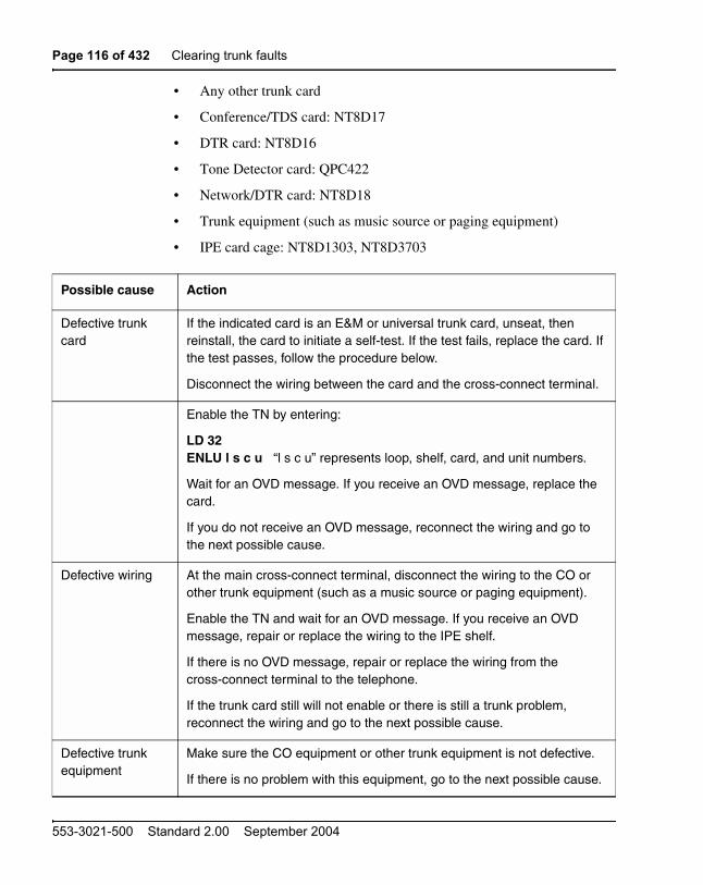
Page 116 of 432 Clearing trunk faults
553-3021-500 Standard 2.00 September 2004
• Any other trunk card
• Conference/TDS card: NT8D17
• DTR card: NT8D16
• Tone Detector card: QPC422
• Network/DTR card: NT8D18
• Trunk equipment (such as music source or paging equipment)
• IPE card cage: NT8D1303, NT8D3703
Possible cause Action
Defective trunk card
If the indicated card is an E&M or universal trunk card, unseat, then reinstall, the card to initiate a self-test. If the test fails, replace the card. If the test passes, follow the procedure below.
Disconnect the wiring between the card and the cross-connect terminal.
Enable the TN by entering:
LD 32ENLU l s c u “l s c u” represents loop, shelf, card, and unit numbers.
Wait for an OVD message. If you receive an OVD message, replace the card.
If you do not receive an OVD message, reconnect the wiring and go to the next possible cause.
Defective wiring At the main cross-connect terminal, disconnect the wiring to the CO or other trunk equipment (such as a music source or paging equipment).
Enable the TN and wait for an OVD message. If you receive an OVD message, repair or replace the wiring to the IPE shelf.
If there is no OVD message, repair or replace the wiring from the cross-connect terminal to the telephone.
If the trunk card still will not enable or there is still a trunk problem, reconnect the wiring and go to the next possible cause.
Defective trunk equipment
Make sure the CO equipment or other trunk equipment is not defective.
If there is no problem with this equipment, go to the next possible cause.

Clearing trunk faults Page 117 of 432
Communication Server 1000M and Meridian 1 Large System Maintenance
Symptom:
Trunk cannot make or receive calls (no OVD message)
You cannot make or receive calls over a trunk, but there is no overload (OVD) or other system message showing that the TN for this trunk is defective or has been disabled. You may need to replace one of the following:
• E&M trunk card: NT8D15
• Universal trunk card: NT8D14
Defective DTR, TDS, or MFS
Use the attendant console to seize trunks and audibly test for dial tone and outpulsing, or use a maintenance telephone and enter:
LD 36TRK l s c u
Note: See the Software Input/Output: Maintenance (553-3001-511) for information on using this test.
If you do not hear outpulsing, the digitone receiver, tone and digit switch, or multi frequency sender may not be sending or receiving digits and the fault will affect more than one trunk. See the procedures for clearing faults on this equipment.
If there is no problem with this equipment, go to the next possible cause.
Defective IPE shelf
Unseat the affected trunk card and enable the TN.
If you do not receive an OVD message, test superloop TNs by entering:
LD 30UNTT l s c u
Test TNs on other loops by entering:
LD 45TEST
If you receive an OVD message, replace the card cage assembly in the module.
Possible cause Action

Page 118 of 432 Clearing trunk faults
553-3021-500 Standard 2.00 September 2004
• Central office trunk card: QPC218, QPC219, QPC450, QPC470
• Any other trunk card
• Conference/TDS card: NT8D17
• DTR card: NT8D16
• Tone Detector card: QPC422
• Network/DTR card: NT8D18
• Trunk equipment (such as music source or paging equipment)
Possible cause Action
Defective trunk equipment
Make sure the CO equipment or other trunk equipment is not defective.
If there is no problem with this equipment, go to the next possible cause.
Disabled or defective TN
Test TNs on superloops by entering:
LD 30UNTT l s c u “l s c u” represents loop, shelf, card, and unit numbers.
Test TNs on other loops by entering:
LD 45TEST
If the test fails, replace the indicated item and test again.
Defective trunk card
If the card is an E&M or universal trunk card, unseat, then reinstall the card to initiate a self-test.
If the test fails, replace the card.
If the test passes, go to the next possible cause.

Clearing trunk faults Page 119 of 432
Communication Server 1000M and Meridian 1 Large System Maintenance
Defective wiring At the main cross-connect terminal, disconnect the wiring to the CO or other trunk equipment.
Enable the TN and wait for an OVD message. If you receive an OVD message, repair or replace the wiring to the IPE shelf.
If there is no OVD message, repair or replace the wiring from the cross-connect terminal to the telephone.
If the trunk card still will not enable or there is still a trunk problem, reconnect the wiring and go to the next possible cause.
Defective DTR, TDS, or MFS
Use the attendant console to seize trunks and audibly test for dial tone and outpulsing, or use a maintenance telephone and enter:
LD 36TRK l s c u
Note: See the Software Input/Output: Maintenance (553-3001-511) for information on using this test.
If you do not hear outpulsing, the digitone receiver, tone and digit switch, or multi frequency sender may not be sending or receiving digits and the fault will affect more than one trunk. See the procedures for clearing faults on this equipment.
If there is no problem with this equipment, go to the next possible cause.
Excessive traffic in the system
Additional trunk cards may be required to handle the traffic in the system. See Traffic Measurement: Formats and Output (553-3001-450).
Possible cause Action

Page 120 of 432 Clearing trunk faults
553-3021-500 Standard 2.00 September 2004

Page 121 of 432
Communication Server 1000M and Meridian 1 Large System Maintenance
130
Clearing attendant console faults
ContentsThis section contains information on the following topics:
Attendant console faults . . . . . . . . . . . . . . . . . . . . . . . . . . . . . . . . . . . . 121
Fault clearing procedures . . . . . . . . . . . . . . . . . . . . . . . . . . . . . . . . . . . 122
Attendant console faultsAttendant consoles are the operator’s interface to the system and its features. Components that can cause an attendant console fault are:
• the console itself or add-on units
• the console power supply
• the building wiring
• the cross-connect from the console to the line circuit
• the unit on the peripheral line card
• the peripheral line card
• the ringing generator
• the peripheral controller card
• the peripheral module power
• the peripheral module backplane

Page 122 of 432 Clearing attendant console faults
553-3021-500 Standard 2.00 September 2004
Attendant console faults typically affect only a single attendant. However, if more than one attendant console is affected, look for the following connections, among others:
• they are on the same line card
• they are on the same module
• they are on the same loop
• they are served by the same peripheral controller
• there is a problem with ringing or tones
Use the following software programs to isolate attendant console faults:
• LD 30 to test network loops
• LD 31 to test sets and consoles
• LD 32 to test peripheral controllers
• LD 45 to perform
— signaling tests
— manual continuity tests
Fault clearing proceduresTable lists common attendant console fault indications. Refer to “How to clear faults” on page 27 for complete fault clearing process.
Table 12Telephone fault indicators
Indicator Possible indications
System messages BSD501—The console (identified by loop, shelf, card, and unit) failed the signaling test. If the unit number is preceded by a minus sign, the console was disabled. There is a console fault or a fault on the peripheral equipment card indicated.

Clearing attendant console faults Page 123 of 432
Communication Server 1000M and Meridian 1 Large System Maintenance
Symptom:
Console cannot make or receive calls (OVD message received)
The attendant console cannot make or receive calls. There is an OVD message indicating that a TN for the attendant console has been disabled. See Telephones and Consoles: Description, Installation, and Operation (553-3001-367) for information on connecting attendant consoles. See Communication Server 1000M and Meridian 1: Large System Installation and Configuration (553-3021-210) for information on system cabling. To replace other equipment, see Communication Server 1000M and Meridian 1:
Visual indicators Red LED lit on associated cards
User reports Trouble with callsTrouble with equipment (such as handset, headset, or display)
WARNINGModule covers are not hinged; do not let go of the cover. Lift the cover away from the module and set it out of your work area.
Table 12Telephone fault indicators
Indicator Possible indications

Page 124 of 432 Clearing attendant console faults
553-3021-500 Standard 2.00 September 2004
Large System Maintenance (553-3021-500). You may need to replace one of the following:
• Attendant console
• IPE card associated with the console
• CE/PE or IPE card cage: NT8D1103, NT8D1303, NT8D3703
Possible cause Action
Defective IPE card Software disable the TN indicated by the OVD message by entering:
LD 32DISU l s c u “l s c u” represents loop, shelf, card, and unit numbers.
Disconnect the wiring between the IPE card and the cross-connect terminal.
Reenable the TN by entering:
ENLU l s c u
and wait for an OVD message.
If you receive a message indicating a problem with the card or unit, replace the card.
If you do not receive a message indicating a problem with the card or unit, reconnect the wiring and go to the next possible cause.
Defective console Disable the TN. Disconnect the wiring from the console to the jack.
Reenable the TN and wait for an OVD message.
If you do not receive an OVD message, replace the console.
If you receive an OVD message, reconnect the wiring and go to the next possible cause.

Clearing attendant console faults Page 125 of 432
Communication Server 1000M and Meridian 1 Large System Maintenance
Symptom:
Console cannot make or receive calls (no OVD message)
The attendant console cannot make or receive calls. There is no OVD message. There may be other system messages indicating that the TN for this console is defective or has been disabled. See Telephones and Consoles: Description, Installation, and Operation (553-3001-367) for information on connecting attendant consoles. See Communication Server 1000M and Meridian 1: Large System Installation and Configuration (553-3021-210) for information on system cabling.
Defective wiring Disable the TN. Disconnect the wiring between the console and the cross-connect terminal.
Reenable the TN and wait for an OVD message.
If you do not receive an OVD message, replace or repair the wiring between the console and the cross-connect terminal.
If you receive an OVD message, replace or repair the wiring between the IPE shelf and the cross-connect terminal.
If there is still a console problem, reconnect all wiring and go to the next possible cause.
Defective backplane
Disable the TN. Unseat the affected IPE card.
Reenable the TN and wait for an OVD message.
If you receive an OVD message, replace the card cage assembly in the module.
Possible cause Action

Page 126 of 432 Clearing attendant console faults
553-3021-500 Standard 2.00 September 2004
Possible cause Action
No power to console
Check the power supply and wiring to see that the console is powered up.
If there is a power supply problem, correct it.
If there is no power problem, go to the next possible cause.
Defective console Test the console by entering:
LD 31
Note: See the Software Input/Output: System Messages (553-3001-411) for information on testing consoles with LD 31.
If the console fails the test, replace it.
If the console passes the test, go to the next possible cause.
Console connected to wrong TNs
Check the cross-connect terminal to make sure the console is connected to the correct TNs.
If the console is not connected correctly, fix the wiring.
If the console is connected correctly, go to the next possible cause.

Clearing attendant console faults Page 127 of 432
Communication Server 1000M and Meridian 1 Large System Maintenance
Symptom:
Indicator or digit display not functioning properly
The attendant console operates, but some LCD indicators or digit displays are not functioning properly. See Telephones and Consoles: Description,
Disabled TN Software disable, then reenable, each TN by entering:
LD 32DISU l s c uENLU l s c u “l s c u” represents loop, shelf, card, and unit numbers.
Test TNs on superloops by entering:
LD 30UNTT l s c u
Test TNs on other loops by entering:
LD 45TEST
If there is still a console problem, go to the next possible cause.
Defective wiring Make sure wiring is properly connected and wires are not interchanged, crossed, or grounded:
— Check the wiring between the console and the cross-connect terminal.
— Check the wiring between the IPE shelf and the cross-connect terminal.
If there is a wiring problem, correct it.
Possible cause Action

Page 128 of 432 Clearing attendant console faults
553-3021-500 Standard 2.00 September 2004
Installation, and Operation (553-3001-367) for information on connecting attendant consoles.
Symptom:
Operator cannot hear or be heard properly
The attendant console operates, but the user cannot hear or be heard properly. See Telephones and Consoles: Description, Installation, and Operation
Possible cause Action
Disconnected or defective power supply
Make sure the required power supplies to the attendant console are connected and are not defective.
If there is still a console problem, go to the next possible cause.
Disabled TN Software disable, then reenable, each TN by entering:
LD 32DISU l s c uENLU l s c u “l s c u” represents loop, shelf, card, and unit numbers.
Test TNs on superloops by entering:
LD 30UNTT l s c u
Test TNs on other loops by entering:
LD 45TEST
If there is still a console problem, go to the next possible cause.
Feature not assigned
Make sure the feature or the indicator is assigned in software (see the Software Input/Output: Administration (553-3001-311)).
If there is still a console problem, go to the next possible cause.
Defective console Test the console by entering:
LD 31
(See the Software Input/Output: System Messages (553-3001-411) for information on testing consoles with LD 31.)
If the console fails the test, replace it.

Clearing attendant console faults Page 129 of 432
Communication Server 1000M and Meridian 1 Large System Maintenance
(553-3001-367) for information on connecting attendant consoles. See Communication Server 1000M and Meridian 1: Large System Installation and Configuration (553-3021-210) for information on system cabling.
Possible cause Action
Defective headset or handset
Make sure the handset or headset is plugged into the correct jack on the console.
Try another handset or headset.
If the test equipment works, replace the faulty handset or headset.
If there is still a console problem, go to the next possible cause.
Defective console Test the console by entering:
LD 31
(Follow the procedures in the Software Input/Output: Maintenance (553-3001-511) to test consoles with LD 31.)
If the console fails the test, replace it.
If the console passes the test, go to the next possible cause.

Page 130 of 432 Clearing attendant console faults
553-3021-500 Standard 2.00 September 2004
Defective IPE card Software disable each TN by entering:
LD 32DISU l s c u “l s c u” represents loop, shelf, card, and unit numbers.
Disconnect the wiring between the IPE card and the cross-connect terminal.
Reenable and test each TN by entering:
ENLU l s c u
Wait for an OVD message. If you receive a message indicating a problem with the card or unit, replace the card.
If you do not receive a message indicating a problem with the card or unit, reconnect the wiring and go to the next possible cause.
Defective wiring to console
Make sure wiring is properly connected and wires are not interchanged, crossed, or grounded:
— Check the wiring between the console and the cross-connect terminal.
— Check the wiring between the IPE shelf and the cross-connect terminal.
If there is a wiring problem, correct it.
Possible cause Action

Page 131 of 432
Communication Server 1000M and Meridian 1 Large System Maintenance
148
Clearing telephone faults
ContentsThis section contains information on the following topics:
Telephone faults . . . . . . . . . . . . . . . . . . . . . . . . . . . . . . . . . . . . . . . . . . 131
Fault clearing procedures . . . . . . . . . . . . . . . . . . . . . . . . . . . . . . . . . . . 132
Telephone faultsTelephones and terminals are the user’s interface to the system and its features. Components that can cause a telephone fault are:
• the telephone itself or add-on units
• the telephone power supply
• the building wiring
• the cross-connect from the telephone to the line circuit
• the unit on the peripheral line card
• the peripheral line card
• the ringing generator
• the peripheral controller card
• the peripheral module power
• the peripheral module backplane

Page 132 of 432 Clearing telephone faults
553-3021-500 Standard 2.00 September 2004
Telephones and terminal faults typically affect only a single user. However, if more than one telephone is affected, look for the following connections, among others:
• they are on the same line card
• they are on the same module
• they are on the same loop
• they are served by the same peripheral controller
• there is a problem with ringing or tones
Use the following software programs and tests to isolate telephone faults:
• LD 30 to test network loops
• LD 31 to test sets and consoles
• LD 32 to test peripheral controllers
• LD 45 to perform signaling tests
• Meridian Modular Telephone (M2006, M2008, M2016S, and M2616) self-test
Fault clearing proceduresTable 13 lists common telephone fault indications. Refer to “How to clear faults” on page 27 for complete fault clearing process.
Table 13Telephone fault indicators (Part 1 of 2)
Indicator Possible indications
System messages BSD501
ERR500
MWL500
NWS501
OVD001–002, 004, 005
XMI messages

Clearing telephone faults Page 133 of 432
Communication Server 1000M and Meridian 1 Large System Maintenance
Symptom:
Telephone cannot make or receive calls (OVD message received)
The telephone cannot make or receive calls. There is an OVD message indicating that the TN for only this telephone has been disabled. See Telephones and Consoles: Description, Installation, and Operation (553-3001-367) for information on connecting telephones. See Communication Server 1000M and Meridian 1: Large System Installation and Configuration (553-3021-210) for information on system cabling. You may need to replace one of the following:
• IPE card
• Telephone
• Wiring between the cross-connect terminal and the telephone
• Wiring between the IPE shelf and the telephone
• CE/PE or IPE card cage: NT8D1103, NT8D1303, NT8D3703
Visual indicators Red LED lit on associated cards
User reports Trouble with calls
Trouble with equipment (such as handset or add-on module)
WARNINGModule covers are not hinged; do not let go of the cover. Lift the cover away from the module and set it out of your work area.
Table 13Telephone fault indicators (Part 2 of 2)

Page 134 of 432 Clearing telephone faults
553-3021-500 Standard 2.00 September 2004
Possible cause Action
Defective IPE card Software disable the TN indicated by the OVD message by entering:
LD 32DISU l s c u “l s c u” represents loop, shelf, card, and unit numbers.
Disconnect the wiring between the IPE card and the cross-connect terminal.
Reenable the TN by entering:
ENLU l s c u
and wait for an OVD message.
If you receive a message indicating a problem with the card or unit, replace the card.
If you do not receive a message indicating a problem with the card or unit, reconnect the wiring and go to the next possible cause.
Defective telephone
Note: If the telephone is a Meridian Modular Telephone, enter:
LD 32IDU l s c u
If there is no response, replace the telephone.If there is an appropriate response, continue this procedure.
Disable the telephone TN. Disconnect the wiring from the telephone to the jack.
Reenable the TN and wait for an OVD message.
If you do not receive an OVD message, replace the telephone.
If you receive an OVD message, reconnect the wiring and go to the next possible cause.

Clearing telephone faults Page 135 of 432
Communication Server 1000M and Meridian 1 Large System Maintenance
Symptom:
Telephone cannot make or receive calls (no OVD message)
The telephone cannot make or receive calls. There is no OVD message or other system message indicating the TN for this telephone is defective or disabled. There may or may not be dial tone when the handset is off-hook. See Telephones and Consoles: Description, Installation, and Operation (553-3001-367) for information on connecting telephones. See Communication Server 1000M and Meridian 1: Large System Installation and Configuration (553-3021-210) for information on system cabling. To replace other equipment, see “Replacing equipment” on page 239.
Defective wiring Disable the TN. Disconnect the wiring between the telephone and the cross-connect terminal.
Reenable the TN and wait for an OVD message.
If you do not receive an OVD message, replace or repair the wiring between the telephone and the cross-connect terminal.
If there is still a problem with the telephone, reconnect all wiring and go to the next possible cause.
Defective backplane
Disable the TN. Unseat the affected IPE card.
Reenable the TN and wait for an OVD message.
If you receive an OVD message, replace the card cage assembly in the module.
Possible cause Action

Page 136 of 432 Clearing telephone faults
553-3021-500 Standard 2.00 September 2004
Possible cause Action
No power to digital telephone
Check the power supply (if one is required) and make sure it is not defective.
If there is a power supply problem, correct it.
If there is no problem with the power supply, go to the next possible cause.
Telephone connected to wrong TNs
Check the cross-connect terminal to make sure the telephone is connected to the correct TN.
If the telephone is not connected correctly, fix the wiring.
If the telephone is connected correctly, go to the next possible cause.
Disabled TN Software disable, then reenable, the telephone TN by entering:
LD 32DISU l s c uENLU l s c u “l s c u” represents loop, shelf, card, and unit numbers.
Test TNs on superloops by entering:
LD 30UNTT l s c u
Test TNs on other loops by entering:
LD 45TEST
If there is still a problem with the telephone, go to the next possible cause.
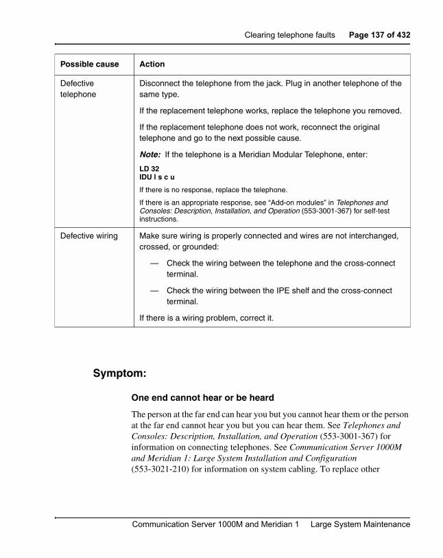
Clearing telephone faults Page 137 of 432
Communication Server 1000M and Meridian 1 Large System Maintenance
Symptom:
One end cannot hear or be heard
The person at the far end can hear you but you cannot hear them or the person at the far end cannot hear you but you can hear them. See Telephones and Consoles: Description, Installation, and Operation (553-3001-367) for information on connecting telephones. See Communication Server 1000M and Meridian 1: Large System Installation and Configuration (553-3021-210) for information on system cabling. To replace other
Defective telephone
Disconnect the telephone from the jack. Plug in another telephone of the same type.
If the replacement telephone works, replace the telephone you removed.
If the replacement telephone does not work, reconnect the original telephone and go to the next possible cause.
Note: If the telephone is a Meridian Modular Telephone, enter:
LD 32IDU l s c u
If there is no response, replace the telephone.
If there is an appropriate response, see “Add-on modules” in Telephones and Consoles: Description, Installation, and Operation (553-3001-367) for self-test instructions.
Defective wiring Make sure wiring is properly connected and wires are not interchanged, crossed, or grounded:
— Check the wiring between the telephone and the cross-connect terminal.
— Check the wiring between the IPE shelf and the cross-connect terminal.
If there is a wiring problem, correct it.
Possible cause Action
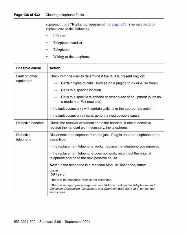
Page 138 of 432 Clearing telephone faults
553-3021-500 Standard 2.00 September 2004
equipment, see “Replacing equipment” on page 239. You may need to replace one of the following:
• IPE card
• Telephone handset
• Telephone
• Wiring to the telephone
Possible cause Action
Fault on other equipment
Check with the user to determine if the fault is present only on:
— Certain types of calls (such as on a paging trunk or a Tie trunk).
— Calls to a specific location.
— Calls to a specific telephone or other piece of equipment (such as a modem or Fax machine).
If the fault occurs only with certain calls, take the appropriate action.
If the fault occurs on all calls, go to the next possible cause.
Defective handset Check the receiver or transmitter in the handset. If one is defective, replace the handset or, if necessary, the telephone.
Defective telephone
Disconnect the telephone from the jack. Plug in another telephone of the same type.
If the replacement telephone works, replace the telephone you removed.
If the replacement telephone does not work, reconnect the original telephone and go to the next possible cause.
Note: If the telephone is a Meridian Modular Telephone, enter:
LD 32IDU l s c u
If there is no response, replace the telephone.
If there is an appropriate response, see “Add-on modules” in Telephones and Consoles: Description, Installation, and Operation (553-3001-367) for self-test instructions.

Clearing telephone faults Page 139 of 432
Communication Server 1000M and Meridian 1 Large System Maintenance
Symptom:
Noise or low volume on all calls
There is noise on the line on all calls or the volume is lower than usual on all calls. See Telephones and Consoles: Description, Installation, and Operation (553-3001-367) for information on connecting telephones. See Communication Server 1000M and Meridian 1: Large System Installation and Configuration (553-3021-210) for information on system cabling. To replace other equipment, see “Replacing equipment” on page 239. You may need to replace one of the following:
• IPE card
Defective IPE card Software disable the telephone TN by entering:
LD 32DISU l s c u “l s c u” represents loop, shelf, card, and unit numbers.
Disconnect the wiring between the IPE card and the cross-connect terminal.
Reenable and test the TN by entering:
ENLU l s c u
Wait for an OVD message. If you receive a message indicating a problem with the card or unit, replace the card.
If you do not receive a message indicating a problem with the card or unit, reconnect the wiring and go to the next possible cause.
Defective wiring to telephone
Make sure wiring is properly connected and wires are not interchanged, crossed, or grounded:
— Check the wiring between the telephone and the cross-connect terminal.
— Check the wiring between the IPE shelf and the cross-connect terminal.
If there is a wiring problem, correct it.
Possible cause Action

Page 140 of 432 Clearing telephone faults
553-3021-500 Standard 2.00 September 2004
• Telephone
• Wiring to the telephone
Possible cause Action
Defective wiring Make sure wiring is properly connected and wires are not interchanged, crossed, or grounded:
— Check the wiring between the telephone and the cross-connect terminal.
— Check the wiring between the IPE shelf and the cross-connect terminal.
If there is a wiring problem, correct it.
If there is no problem with the wiring, go to the next possible cause.
Defective telephone
Disconnect the telephone from the jack. Plug in another telephone of the same type.
If the replacement telephone works, replace the telephone you removed.
If the replacement telephone does not work, reconnect the original telephone and go to the next possible cause.
Note: If the telephone is a Meridian Modular Telephone, enter:
LD 32IDU l s c u
If there is no response, replace the telephone.
If there is an appropriate response, see “Add-on modules” in Telephones and Consoles: Description, Installation, and Operation (553-3001-367) for self-test instructions.

Clearing telephone faults Page 141 of 432
Communication Server 1000M and Meridian 1 Large System Maintenance
Symptom:
Defective indicator, digit display, or component
The telephone can place and receive calls, but one or more LED or LCD indicators, digit displays, or components (such as a handsfree unit) are not working. See Telephones and Consoles: Description, Installation, and Operation (553-3001-367) for information on connecting telephones. To replace other equipment, see “Replacing equipment” on page 239. You may need to replace one of the following:
• Power supply to telephone
• IPE card
• Telephone
Symptom:
Defective feature
The telephone can make and receive calls, but one or more of its features (such as call transfer or ring again) is not working. See Telephones and
Defective IPE card Software disable the telephone TN by entering:
LD 32DISU l s c u “l s c u” represents loop, shelf, card, and unit numbers.
Disconnect the wiring between the IPE card and the cross-connect terminal.
Reenable and test the TN by entering:
ENLU l s c u
Wait for an OVD message. If you receive a message indicating a problem with the card or unit, replace the card.
Possible cause Action

Page 142 of 432 Clearing telephone faults
553-3021-500 Standard 2.00 September 2004
Possible cause Action
Telephone has incorrect software parameters
Disconnect, then reconnect, power to the telephone to force a reset and parameter download.
If the fault is not cleared, go to the next possible cause.
No power to digital telephone
Check the power supply (if one is required) and make sure it is not defective.
If there is a power supply problem, correct it.
If there is no problem with the power supply, go to the next possible cause.
Defective telephone
Disconnect the telephone from the jack. Plug in another telephone of the same type.
If the replacement telephone works, replace the telephone you removed.
If the replacement telephone does not work, reconnect the original telephone and go to the next possible cause.
Note: If the telephone is a Meridian Modular Telephone, enter:
LD 32IDU l s c u
If there is no response, replace the telephone.If there is an appropriate response, see “Add-on modules” in Telephones and Consoles: Description, Installation, and Operation (553-3001-367) for self-test instructions.
Feature not assigned
Make sure the feature or the indicator is assigned in software (see the Software Input/Output: Administration (553-3001-311)).

Clearing telephone faults Page 143 of 432
Communication Server 1000M and Meridian 1 Large System Maintenance
Consoles: Description, Installation, and Operation (553-3001-367) for information on connecting telephones.
Symptom:
Defective add-on module
The telephone can make and receive calls, but an add-on module connected to it is not working. See Telephones and Consoles: Description, Installation, and Operation (553-3001-367) for information on connecting telephones. You may need to replace one of the following:
• Add-on module
Possible cause Action
Feature not assigned
Make sure the feature or the indicator is assigned in software (see the Software Input/Output: Administration (553-3001-311)).
If there is still a console problem, go to the next possible cause.
Defective telephone
Disconnect the telephone from the jack. Plug in another telephone of the same type.
If the replacement telephone works, replace the telephone you removed.
If the replacement telephone does not work, reconnect the original telephone and go to the next possible cause.
Note: If the telephone is a Meridian Modular Telephone, enter:
LD 32IDU l s c u
If there is no response, replace the telephone.
If there is an appropriate response, see “Add-on modules” in Telephones and Consoles: Description, Installation, and Operation (553-3001-367) for self-test instructions.

Page 144 of 432 Clearing telephone faults
553-3021-500 Standard 2.00 September 2004
• Data option card
• Power supply for add-on module
Symptom:
Cannot dial from 2500 telephone
A user cannot dial from a 2500 telephone. The condition may exist on more than one telephone and may be intermittent. The telephone may occasionally experience a “no dial tone” condition. Calls from other types of sets are not affected. See Telephones and Consoles: Description, Installation, and Operation (553-3001-367) for information on connecting telephones. See Communication Server 1000M and Meridian 1: Large System Installation and Configuration (553-3021-210) for information on system cabling. To replace other equipment, see “Replacing equipment” on page 239. You may need to replace one of the following:
• DTR card: NT8D16
• Tone Detector card: QPC422
• Network/DTR card: NT8D18
• Telephone
• Wiring to the telephone
Possible cause Action
Defective power supply for add-on module
If the add-on module requires a separate power supply, make sure it is properly connected and in working order.
If there is still a problem with the telephone, go to the next possible cause.
Defective add-on module
Replace the add-on module.
Defective data option card
If the fault is with a data add-on module, replace the data option card.

Clearing telephone faults Page 145 of 432
Communication Server 1000M and Meridian 1 Large System Maintenance
Symptom:
No ring on 500 and 2500 telephones
Both 500 and 2500 telephones do not ring. One or several sets in the same module are experiencing the problem. See Telephones and Consoles: Description, Installation, and Operation (553-3001-367) for information on connecting telephones. See Communication Server 1000M and Meridian 1: Large System Installation and Configuration (553-3021-210) for information
Possible cause Action
Defective telephone
If only one telephone is affected, replace it.
If there is still a problem with the telephone, go to the next possible cause.
Defective wiring If only one telephone is affected, make sure wiring is properly connected and wires are not interchanged, crossed, or grounded:
— Check the wiring between the telephone and the cross-connect terminal.
— Check the wiring between the IPE shelf and the cross-connect terminal.
If there is a wiring problem, correct it.
If there is still a problem with the telephone, go to the next possible cause.
Defective digitone receiver
If the condition is intermittent or more than one telephone is affected, test the digitone receivers in the system by entering:
LD 34DTR l s c u “l s c u” represents loop, shelf, card, and unit numbers of
the DTR.
Replace any units that fail the test.
If there is still a problem with the telephone, go to the next possible cause.
Excessive Digitone traffic
Additional digitone receivers may be required to handle the traffic in the system. See Traffic Measurement: Formats and Output (553-3001-450).

Page 146 of 432 Clearing telephone faults
553-3021-500 Standard 2.00 September 2004
on system cabling. To replace other equipment, see “Replacing equipment” on page 239. You may need to replace one of the following:
• Ringing generator: NT6D42, NT8D21
• IPE card
• Telephone
• Wiring to the telephone
• CE/PE or IPE card cage: NT8D1103, NT8D1303, NT8D3703
Possible cause Action
Defective telephone
If only one telephone is affected, replace it.
If there is still a problem with the telephone, go to the next possible cause.
Defective wiring If only one telephone is affected, make sure wiring is properly connected and wires are not interchanged, crossed, or grounded:
— Check the wiring between the telephone and the cross-connect terminal.
— Check the wiring between the IPE shelf and the cross-connect terminal.
If there is a wiring problem, correct it.
If there is still a problem with the telephone, go to the next possible cause.
Defective IPE card Software disable the telephone TN by entering:
LD 32DISU l s c u “l s c u” represents loop, shelf, card, and unit numbers.
Disconnect wiring between the IPE card and the cross-connect terminal.
Reenable and test the TN by entering:
ENLU l s c u
Wait for an OVD message. If you receive a message indicating a problem with the card or unit, replace the card.
If you do not receive a message indicating a problem with the card or unit, reconnect the wiring and go to the next possible cause.

Clearing telephone faults Page 147 of 432
Communication Server 1000M and Meridian 1 Large System Maintenance
Defective controller card
If several sets on different cards in the same loop are affected, replace the controller card.
If there is still a problem with the telephone, reinstall the original controller card and go to the next possible cause.
Defective ringing generator
If several sets on different cards in the same module are affected, replace the ringing generator for the shelf (even if the green LED on the unit is lit).
If there is still a problem with the telephone, reinstall the original ringing generator and go to the next possible cause.
Defective backplane
If the green LED is lit on the ringing generator and the fault persists, replace the card cage assembly in the module.
Possible cause Action
Page 148 of 432 Clearing telephone faults
553-3021-500 Standard 2.00 September 2004

Page 149 of 432
Communication Server 1000M and Meridian 1 Large System Maintenance
166
Simple Network Management Protocol
ContentsThis section contains information on the following topics:
Introduction . . . . . . . . . . . . . . . . . . . . . . . . . . . . . . . . . . . . . . . . . . . . . . 150MIBs . . . . . . . . . . . . . . . . . . . . . . . . . . . . . . . . . . . . . . . . . . . . . . . . . 150SNMP Overview . . . . . . . . . . . . . . . . . . . . . . . . . . . . . . . . . . . . . . . 151
Configuration . . . . . . . . . . . . . . . . . . . . . . . . . . . . . . . . . . . . . . . . . . . . 152
Supported MIBs . . . . . . . . . . . . . . . . . . . . . . . . . . . . . . . . . . . . . . . . . . 154MIB security. . . . . . . . . . . . . . . . . . . . . . . . . . . . . . . . . . . . . . . . . . . 155
Configuration of system group MIB parameters. . . . . . . . . . . . . . . . . . 155Print commands . . . . . . . . . . . . . . . . . . . . . . . . . . . . . . . . . . . . . . . . 159Config.ini file . . . . . . . . . . . . . . . . . . . . . . . . . . . . . . . . . . . . . . . . . . 159
Traffic MIB . . . . . . . . . . . . . . . . . . . . . . . . . . . . . . . . . . . . . . . . . . . . . . 160
Community name strings . . . . . . . . . . . . . . . . . . . . . . . . . . . . . . . . . . . 160
Test Alarm utility . . . . . . . . . . . . . . . . . . . . . . . . . . . . . . . . . . . . . . . . . 162
EDT and EPT . . . . . . . . . . . . . . . . . . . . . . . . . . . . . . . . . . . . . . . . . . . . 164
Backup and restore . . . . . . . . . . . . . . . . . . . . . . . . . . . . . . . . . . . . . . . . 165LD 43 . . . . . . . . . . . . . . . . . . . . . . . . . . . . . . . . . . . . . . . . . . . . . . . . 165LD 143 . . . . . . . . . . . . . . . . . . . . . . . . . . . . . . . . . . . . . . . . . . . . . . . 166

Page 150 of 432 Simple Network Management Protocol
553-3021-500 Standard 2.00 September 2004
Introduction
MIBs
In typical IP network devices, the operator requires a large amount of management information to properly run the device. This information is kept on the system and can be made available to network management systems through Simple Network Management Protocol (SNMP). The information itself is kept on the device (conceptually) in a database, referred to as a Management Information Base (MIB). The network management system can query the MIB through SNMP query commands (called gets), and in some cases can write into the MIB through SNMP set commands.
For the Network Management System (NMS) to communicate with the agent on a managed device, the NMS must have a description of all manageable objects the agent knows about. Therefore, each type of agent has an associated document, called a MIB Module, which contains these descriptions. MIB Module files are loaded into the NMS. MIB Modules are frequently referred to as “MIBs”. The primary purpose of the MIB module is to provide a name, structure and a description for each of the manageable objects a particular agent knows about.
The NMS uses two kinds of MIB modules:
• a generic MIB Module that describes the structure of the data that can be retrieved by the NMS
• a trap MIB Module that describes the structure of the data sent by the device agent as an SNMP trap
MIB data is arranged in a tree structure. Each object (each item of data) on the tree has an identifier, called an Object ID (OID), which uniquely identifies the variable. To prevent naming conflicts and provide organization, all major device vendors, as well as certain organizations, are assigned a branch of this tree structure (referred to as the “MIB Tree”). The MIB Tree is managed by the Internet Assigned Numbers Authority (IANA). Each object on the MIB Tree has a number and a name, and the complete path from the top of the tree down to the point of interest forms the name.

Simple Network Management Protocol Page 151 of 432
Communication Server 1000M and Meridian 1 Large System Maintenance
An SNMP MIB must be written in Abstract Notation One (ASN.1) format to conform with the SNMP standards.
SNMP Overview
CS 1000 Release 4.0 software introduces the following Simple Network Management Protocol (SNMP) features:
• Support of standard MIBs on the Call Server. See “Supported MIBs” on page 154.
• Support of the Entity MIB on the Call Server. See “Supported MIBs” on page 154.
• Configurable system group MIB values for the Call Server and synchronization of those values to the Signaling Servers and Media Cards when a data dump is performed. See “Configuration of system group MIB parameters” on page 155.
• Accessibility of Quality of Service (QoS) data through an SNMP MIB. See “Traffic MIB” on page 160.
• Configurable community name strings on the Call Server which are synchronized to the Signaling Servers and Media Cards when a data dump is performed. See “Community name strings” on page 160.
• An alarm test utility, providing the ability to manually send out a test SNMP trap from the Call Server to confirm the SNMP configuration is correct. See “Test Alarm utility” on page 162.
• The ability to import/export the EPT from the Call Server to removable media, and from the removable media back to the Call Server. See “EDT and EPT” on page 164.
CS 1000 Release 4.0 also provides enhancements to the following SNMP features:
• An increase in the number of entries allowed in the Event Preference Table (EPT) from 200 to 500. See“EDT and EPT” on page 164.
• The ability to reload the EPT from disk using an overlay command. See “EDT and EPT” on page 164.

Page 152 of 432 Simple Network Management Protocol
553-3021-500 Standard 2.00 September 2004
• New LD 117 commands to print the Event Default Table (EDT) or EPT entries, based on the severity of the system message. See “EDT and EPT” on page 164.
• Removal of community name strings from the config.ini file. See “Config.ini file” on page 159.
• Modifications to LD 143 and LD 43 for the backup/restore of the Call Server’s SNMP configuration files. See “Backup and restore” on page 165.
ConfigurationDifferent tools, such as the Command Line Interface (CLI), Element Manager, and Optivity Telephony Manager (OTM) are used to configure SNMP elements for a system, depending on the system platform (CS 1000E, CS 1000S, CS 1000M, or Meridian 1) and the network device. See Table 14.
Table 14SNMP elements and where they are configured (Part 1 of 2)
SNMP configuration of....... CLI Element Manager OTM
Call Server
Community name strings(Note 1)
Yes Yes Yes
Trap destinations Yes No No
sysgroup MIB info Yes Yes Yes
EDT/EPT edits Yes No Yes
Signaling Server
Community name strings
See Note 1. See Note 1. See Note 1.
Trap destinations No Yes No

Simple Network Management Protocol Page 153 of 432
Communication Server 1000M and Meridian 1 Large System Maintenance
sysgroup MIB info No Yes No
Media Cards
Community name strings
See Note 1. See Note 1. See Note 1.
Trap destinations No Yes See Note 2.
sysgroup MIB info No Yes See Note 2.See Note 3.
Note 1: Propagated to the Signaling Server and Media Cards on EDD.
Note 2: On a Meridian 1 (no Signaling Server), OTM is used to provision the Media Cards and other ITG devices.
Note 3: For the Meridian 1 (no Signaling Server), OTM can use the same values as for the Call Server.
Table 14SNMP elements and where they are configured (Part 2 of 2)
SNMP configuration of....... CLI Element Manager OTM

Page 154 of 432 Simple Network Management Protocol
553-3021-500 Standard 2.00 September 2004
Supported MIBsTable 15 lists the standard and enterprise-specific MIBs supported in CS 1000 Release 4.0 for each device.
Table 15Supported MIBs (Part 1 of 2)
Component Standard MIB Enterprise-specific MIB
Call Server • System group (RFC 1213)
• Interface group (RFC 2863)
• IP group (RFC 2011)
• UDP group (RFC 2013)
• TCP group (RFC 2012)
• ICMP group (RFC 2011)
• SNMP group (RFC 3418)
• Entity group (RFC 2737)(only the following two sub-groups)- Physical- General
• Trap group – Rel 4_0 Call Server trap.mib

Simple Network Management Protocol Page 155 of 432
Communication Server 1000M and Meridian 1 Large System Maintenance
MIB security
For security purposes, read and write community name strings are used to control access to all MIB data.
Configuration of system group MIB parametersCommands have been added to LD 117 to modify the parameters for MIB groups. This includes the parameters needed for the system group MIB (1.3.6.1.2.1.1). The system group provides the basic information about the identity of the system such as system name, system location, and system contact. By default, a set of variables are defined for the system group MIB,
Signaling Server
• System group (RFC 1213)
• Interface group (RFC 2863)
• IP group (RFC 2011)
• UDP group (RFC 2013)
• TCP group (RFC 2012)
• ICMP group (RFC 2011)
• SNMP group (RFC 3418)
• Trap group – Rel 4_0 Sig Server trap.mib
• Zonetrafficrpt group – zonetrafficrpt.mib
Media Card • System group (RFC 1213)
• Interface group (RFC 2863)
• IP group (RFC 2011)
• UDP group (RFC 2013)
• TCP group (RFC 2012)
• ICMP group (RFC 2011)
• SNMP group (RFC 3418)
• Trap group – Rel 4_0 IP Line trap.mib
Table 15Supported MIBs (Part 2 of 2)
Component Standard MIB Enterprise-specific MIB

Page 156 of 432 Simple Network Management Protocol
553-3021-500 Standard 2.00 September 2004
but they are also configurable in LD 117 using the commands listed in Table 16.
Both the standard MIB read-only community name string and the enterprise-specific MIB community name strings (public, admingroup2, and admingroup3) are defined by default. However, they can also be configured in LD 117.
The system group MIB parameters and the community name strings are configured on the Call Server and synchronized to the Signaling Server and the Media Cards when a data dump is performed. As well, they are synchronized when a link is established between a Signaling Server or Media Card and the Call Server.
Table 16LD 117 - Configure system group MIB parameters (Part 1 of 3)
=> Command Description
CHG NAV_SITE aa... a Change the navigation site name (for example, MyCity) where:
• aa...a = a string with maximum length of 32 characters
• default = Navigation Site Name
Note: Use a single X to clear the field.
CHG NAV_SYSTEM aa... a Change the navigation site name (for example, Station Switch) where:
• aa...a = a string with a maximum length of 32 characters
• default = Navigation Site Name
Note: Use a single X to clear the field.

Simple Network Management Protocol Page 157 of 432
Communication Server 1000M and Meridian 1 Large System Maintenance
CHG SNMP_SYSCONTACT aa... a Change the contact person name for this machine where:
• aa...a = a string with a maximum length of 100 characters
• default = System Contact
Use a single X to clear the field.
CHG SNMP_SYSLOC aa...a Change the defined physical location for this machine where:
• aa...a = a string with a maximum length of 100 characters
• default = System Location
Use a single X to clear the field.
CHG SNMP_SYSNAME aa...a Change the name assigned to this machine where:
• aa...a = a string with a maximum length of 100 characters
Default = Navigation Site Name: Navigation System Name : Hostname
Use a single X to clear the field.
CHG SNMP_SYSNAME NAV Revert the name assigned to this machine to the default name. The default name is comprised of the currently configured <NAV_SITE> : <NAV_SYSTEM> : <HOSTNAME>.
Table 16LD 117 - Configure system group MIB parameters (Part 2 of 3)
=> Command Description
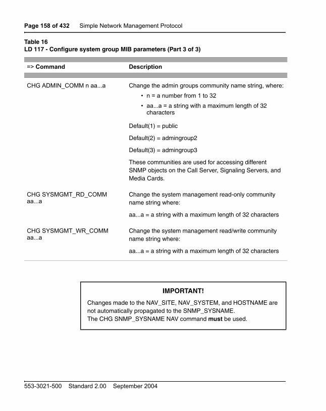
Page 158 of 432 Simple Network Management Protocol
553-3021-500 Standard 2.00 September 2004
CHG ADMIN_COMM n aa...a Change the admin groups community name string, where:
� n = a number from 1 to 32
� aa...a = a string with a maximum length of 32 characters
Default(1) = public
Default(2) = admingroup2
Default(3) = admingroup3
These communities are used for accessing different SNMP objects on the Call Server, Signaling Servers, and Media Cards.
CHG SYSMGMT_RD_COMM aa...a
Change the system management read-only community name string where:
aa...a = a string with a maximum length of 32 characters
CHG SYSMGMT_WR_COMM aa...a
Change the system management read/write community name string where:
aa...a = a string with a maximum length of 32 characters
IMPORTANT!
Changes made to the NAV_SITE, NAV_SYSTEM, and HOSTNAME are not automatically propagated to the SNMP_SYSNAME. The CHG SNMP_SYSNAME NAV command must be used.
Table 16LD 117 - Configure system group MIB parameters (Part 3 of 3)
=> Command Description

Simple Network Management Protocol Page 159 of 432
Communication Server 1000M and Meridian 1 Large System Maintenance
Note: The data dump (EDD) command saves the configurable system group MIB parameters and community name strings to a file called syscfg.db, which is saved at c:/u/db (Small Systems) or /u/db (Large Systems).
For more detailed information on configuring MIBs, see Simple Network Management Protocol: Description and Maintenance (553-3001-519).
Print commands
Printing the system group MIB parameters and community name strings is done through LD 117. See Table 17.
Config.ini file
Since the community name strings are synchronized when a link is established between a Signaling Server/Media Card and the Call Server, the IP Telephony devices no longer read the config.ini file to retrieve the community strings. Therefore the community name strings have been removed from the config.ini file.
Table 17LD 117 - Print system group MIB parameters and community name strings
=> Command Description
PRT NAV_SITE Print the navigation site name.
PRT NAV_SYSTEM Print the navigation system name.
PRT SNMP_SYSGRP Print all parameters of the MIB system group.
PRT ADMIN_COMM Print the administration group read-only community name strings.
PRT SYSMGMT_COMM Print the system management community name strings

Page 160 of 432 Simple Network Management Protocol
553-3021-500 Standard 2.00 September 2004
Traffic MIBThe Zonetrafficrpt MIB on the Signaling Server handles traffic report parameters generated on the Call Server. The SNMP manager sends an SNMP query to the Signaling Server to retrieve the Zonetrafficrpt parameters. The Signaling Server communicates with the Call Server to retrieve the information from the traffic report and respond to the SNMP query. The SNMP agent on the Signaling Server incorporates the Zonetrafficrpt MIB and handles SNMP queries to the Zonetrafficrpt MIB. The Zonetrafficrpt parameter values from the Call Server are transferred to the Signaling Server. On the Call Server, the Zonetrafficrpt parameters are accessed through LD 2 and LD 117.
The Zonetrafficrpt MIB consists of traffic parameters for a zone provisioned on the Call Server. The two sets of parameters are intra-zone parameters and inter-zone parameters. Each parameter is assigned an object ID in the MIB. For further information about the Zonetrafficrpt traffic parameters that are available, refer to Simple Network Management Protocol: Description and Maintenance (553-3001-519).
Community name stringsRead-only and read/write community name strings control access to all MIB data. A community name string is defined by default to access standard MIBs. A set of administrator community name strings is supported with read-only privileges, with the default strings of “public”, “admingroup2”, and “admingroup3”. The first and third community name strings provide access to system group MIB variables, while the second community name string provides access to all MIBs.
New commands are created in LD 117 to configure MIB community name strings for read-only access to Call Server MIBs (system group MIB objects) and for read/write access to Signaling Server/Media Card MIBs. Table 18 on page 161 lists the Call Server community name strings. Table 19 on page 162 lists the Signaling Server/Media Card community name strings.

Simple Network Management Protocol Page 161 of 432
Communication Server 1000M and Meridian 1 Large System Maintenance
Table 18Call Server community name strings
Community Name(User group)
Access privileges Interface View
Where configured
ADMIN_COMM(1)(public)
read ELAN Network system group MIB
LD 117
ADMIN_COMM(2)(admingroup2)
read ELAN Network All MIBs LD 117
ADMIN_COMM(3)(admingroup3)
read ELAN Network system group MIB
LD 117
SYSMGMT_RD_COMM(otm123)
read ELAN Network All MIBs LD 117
SYSMGMT_WR_COMM(otm321)
read/write ELAN Network CorpDir MIB LD 117

Page 162 of 432 Simple Network Management Protocol
553-3021-500 Standard 2.00 September 2004
The community name strings used by the Signaling Server and Media Cards are synchronized from the Call Server to the Signaling Server and Media Cards when a data dump is performed. As well, they are synchronized when a link is established between a Signaling Server or Media Card and the Call Server.
Test Alarm utilityA diagnostic utility has been added to the Call Server to be used for alarm testing by entering a command in LD 117. The Test Alarm utility simulates an alarm to verify that the alarms are generated correctly and sent to their configured destinations. The alarm is sent to the trap destination list configured on the system, using LD 117 and the Open Alarm feature.
The TEST ALARM command creates and sends an open_alarm (trap type 10) to the trap destination list and displays a message on the console. The alarm test utility sends a trap for any parameter specified.
Table 19Signaling Server/Media Cards community name strings
Community Name(User group)
Access privileges Interface View
Where configured
ADMIN_COMM(1)(public)
read ELAN Network system group MIB
LD 117
ADMIN_COMM(2)(admingroup2)
read ELAN Network All MIBs LD 117
ADMIN_COMM(3)(admingroup3)
read ELAN Network Zonetrafficrpt MIB
(Signaling Server only)
system group MIB
(Media Cards only)
LD 117

Simple Network Management Protocol Page 163 of 432
Communication Server 1000M and Meridian 1 Large System Maintenance
The flow of the message travels through the following:
• Event Default Table (EDT) to assign correct severity if system message is valid; otherwise, system message is assigned a severity of Info
• Event Preference table (EPT) to modify severity or suppress system message based on threshold
If the Test Alarm utility uses a valid system message and correctly sends a trap to the trap destination, the same system message, if it occurs on the system, is not guaranteed to be sent as a trap. Some system messages currently do not generate a trap. The LD 117 TEST ALARM command is described in Table 20.
Table 20LD 117 - Test alarm command
=> Command Description
TEST ALARM aaaa nnnn Generate an alarm where:
aaaa = any character sequence.However, to test how an existing system message category (for example, BUG, ERR, INI) would appear in an alarm browser, use an existing system message.
nnnnn = any numeric sequence (for example, 3458) and is optional, defaulting to 0000
The actual output on the TTY is the system message passed as the parameter; for example:
BUG1234
The actual trap sent to the trap destination list is trap type 10 with the following details:
operator description = ‘This is a test’
operator data = ‘This is a test’
error code = aaaannnn
The rest of the binding variables are NULL.

Page 164 of 432 Simple Network Management Protocol
553-3021-500 Standard 2.00 September 2004
EDT and EPTThe Event Default Table (EDT) and Event Preference Table (EPT) are repositories on the Call Server for storing system event information.
The EDT contains a list of system events that are generated on the system. Each event contains an event code, a description, and severity information. The EPT is used to override the severity of an event assigned in the EDT. The EPT can also be used to set escalation thresholds and suppression thresholds for certain event severities.
The number of entries allowed in the EPT has been increased from 200 to 500.
Additional commands are added to LD 117 to import and export an EPT file from/to removable media, to load an updated EPT file into memory, and to print the entries in the EDT and EPT. See Table 21.
Table 21LD 117 - EDT and EPT commands
=> Command Description
EXPORT EPT The EPT file stored on the hard disk (/u/db/ smpserv.db) is copied to the floppy / PC Card drive (a:/smpserv.db).
IMPORT EPT The EPT file stored on the floppy / PC Card (a:/smpserv.db) drive is copied to the hard drive (/u/db/smpserv.db).
RELOAD EPT The new/modified EPT file is loaded into memory from disk (/u/db/smpserv.db).
PRTS EPTseverity <eventID> <eventID>
The entries in the EPT can be listed based on the severity field for all entries or the specified range of entries.
PRTS EDT severity <eventID> <eventID>
The entries in the EDT can be listed based on the severity field for all entries or the specified range of entries.

Simple Network Management Protocol Page 165 of 432
Communication Server 1000M and Meridian 1 Large System Maintenance
Error messages are issued if the import or export of the EPT file was not successful.
Backup and restore
LD 43
The LD 43 commands listed in Table 22 have been modified to enable a backup and restore of the Call Server system group MIB variables, System Navigation variables, and community name strings.
Table 22LD 43 - Backup and restore commands
Command Description
EDD The Call Server system group MIB variables, System Navigation variables, and community name strings are dumped to disk as a file when this command is executed. As well, this file is backed up to the A: drive floppy (Large Systems) or to the internal Z: drive (Small Systems).
BKO The new file created to store the system group MIB variables, System Navigation variables, and community name strings is copied from the primary device to the backup (external storage) device.
RES The new file created to store the system group MIB variables, System Navigation variables, and community name strings is restored from the backup (external storage) device to the primary device.

Page 166 of 432 Simple Network Management Protocol
553-3021-500 Standard 2.00 September 2004
LD 143
Large systems
The LD 143 Large System-specific commands listed in Table 23 have been modified to enable the backup and restore of the system group MIB variables, System Navigation variables, and community name strings using floppy disks.
More informationFor more detailed information on SNMP, refer to Simple Network Management Protocol: Description and Maintenance (553-3001-519).
Table 23LD 143 - Large System backup and restore commands using floppy disks
Command Description
ABKO The new file created to store the system group MIB variables, System Navigation variables, and community name strings is backed up to floppy disks.
ARES The new file created to store the system group MIB variables, System Navigation variables, and community name strings is restored from floppy disks.

Page 167 of 432
Communication Server 1000M and Meridian 1 Large System Maintenance
184
Proactive Voice-quality Management
ContentsThis section contains information on the following topics:
Introduction . . . . . . . . . . . . . . . . . . . . . . . . . . . . . . . . . . . . . . . . . . . . . . 168
How voice quality monitoring works . . . . . . . . . . . . . . . . . . . . . . . . . . 169
Feature packaging . . . . . . . . . . . . . . . . . . . . . . . . . . . . . . . . . . . . . . . . . 171
Feature implementation. . . . . . . . . . . . . . . . . . . . . . . . . . . . . . . . . . . . . 171Task summary list. . . . . . . . . . . . . . . . . . . . . . . . . . . . . . . . . . . . . . . 171LD 117 - Configure voice-quality metric thresholds . . . . . . . . . . . . 172LD 117 - Print voice-quality metric thresholds . . . . . . . . . . . . . . . . 174LD 117 - Configure voice-quality sampling (polling) . . . . . . . . . . . 174LD 117 - Configure zone alarm-notification levels . . . . . . . . . . . . . 175LD 117 - Print zone alarm-notification levels . . . . . . . . . . . . . . . . . 180
New voice-quality alarms . . . . . . . . . . . . . . . . . . . . . . . . . . . . . . . . . . . 180
Diagnosing and isolating voice-quality problems. . . . . . . . . . . . . . . . . 181
SNMP interface . . . . . . . . . . . . . . . . . . . . . . . . . . . . . . . . . . . . . . . . . . . 182
Heterogeneous environments . . . . . . . . . . . . . . . . . . . . . . . . . . . . . . . . 182

Page 168 of 432 Proactive Voice-quality Management
553-3021-500 Standard 2.00 September 2004
IntroductionProactive Voice quality Management (PVQM) includes the following enhancements for CS 1000 Release 4.0:
• Monitoring of voice-quality metrics (for example, latency, jitter, packet loss, and R-Value) for the IP Phone and voice gateway endpoints.
• Threshold configuration (for example, Warning and Unacceptable) of voice-quality metrics in Overlay 117. Thresholds are used to classify system performance as good, poor, and unacceptable.
• SNMP alarm generation when voice-quality metric thresholds are violated on a per-call or bandwidth zone basis.
• Voice quality related SNMP alarm control, on a zone basis, by configuring Alarm Notification Levels in Overlay 117. Alarm control assists in isolating voice-quality problems and reducing network traffic.
• Recording of voice-quality metric threshold violations in Traffic Report 16. Traffic Report 16 is now accessible in Overlay 2 and SNMP MIB.
• Retrieval of Operational Measurement (OM) reports containing hourly summations of the voice-quality metrics and endpoint registration activity. R-Value information is now available in OM reports.
• Network diagnostic utilities to identify, isolate, and report network problems affecting voice quality. The diagnostic utilities are available by using the CLI or IP Phones with Phase 2 software. The utilities include Traceroute, Ping, Ethernet statistics, IP Network statistics, UNIStim/Reliable User Data Protocol (RUDP) statistics, Real-Time Control Protocol (RTCP) statistics, and Dynamic Host Control Protocol (DHCP) data.
These enhancements assist network administrators and craft persons to:
• Make informed decisions for capacity planning and Quality of Service (QoS) network engineering.
• Monitor the performance of their systems.
• Diagnose, isolate, and correct networking problems that cause deterioration in voice quality.

Proactive Voice-quality Management Page 169 of 432
Communication Server 1000M and Meridian 1 Large System Maintenance
How voice quality monitoring worksThe PVQM feature monitors voice quality by polling IP endpoints during a call, and at the end of a call, to sample the following voice-quality metrics:
• Latency - the length of time needed for information to travel through the network, value expressed in seconds
• Jitter - the variability in latency, value expressed in seconds
• Packet Loss - the number of packets lost during transmission, value expressed in percentage
• R-Value - measurement of audio quality using ITU E-Model
The sampled metrics are compared to user-configured thresholds in order to determine system performance. When sampled metrics exceed configured thresholds, statistics are generated on the system.
Note: For details on configuring metric thresholds, refer to “LD 117 - Configure voice-quality metric thresholds” on page 172.
Statistics for each metric are collected on the Signaling Server or Voice Gateway Media Card to create a Quality Detail Report (QDR). The QDR summarizes metric threshold violations into one of the following categories:
• Warning
• Unacceptable
Each summarized QDR record is added to the IP Phone Zone Traffic Report 16. The enhanced traffic report summarizes the voice quality over the reporting period on a zone-by-zone basis to allow the administrator to view the overall voice quality.
An SNMP alarm is generated when a voice-quality metric threshold exceeds Warning or Unacceptable status. For details on controlling the number of SNMP alarms generated, refer to “LD 117 - Configure zone alarm-notification levels” on page 175.
Figure 8 on page 170 illustrates PVQM within the Voice over IP (VoIP) system.

Page 170 of 432 Proactive Voice-quality Management
553-3021-500 Standard 2.00 September 2004
Figure 8Voice-quality monitoring flow diagram
Legend
1 IP Phones and endpoints are polled during a call, and at the end of a call, to extract voice-quality statistics.
2 Statistics for each metric are collected on the Signaling Server or Voice Gateway Media Card.
3 Voice-quality statistics are compared to threshold settings and a QDR is created.
4 The QDR is forwarded to the Call Server for reporting purposes.
5 An SNMP alarm is generated when voice-quality metric exceeds the Warning or Unacceptable threshold.

Proactive Voice-quality Management Page 171 of 432
Communication Server 1000M and Meridian 1 Large System Maintenance
Feature packagingMonitoring of all other voice-quality metrics is available with base CS 1000 Release 4.0 software. To enable monitoring of the R-Value audio quality metric, the Proactive Voice quality Management (PVQM) package 401 is required.
Supported system typesPVQM is supported by CS 1000 Release 4.0 and Meridian 1 systems equipped with Voice Gateway Media Cards running IP Line 4.0.
Feature implementationThe system implements this feature during an installation or upgrade to the PVQM_401 software package, available from Feature Service Level 2 - Enhanced Business Services.
Task summary list
The following is a summary of the tasks in this section:
1 LD 117 - Configure voice-quality metric thresholds.
2 LD 117 - Print voice-quality metric thresholds.
3 LD 117 - Configure voice-quality sampling (polling).
4 LD 117 - Configure zone alarm-notification levels.
5 LD 117 - Print zone alarm-notification levels.
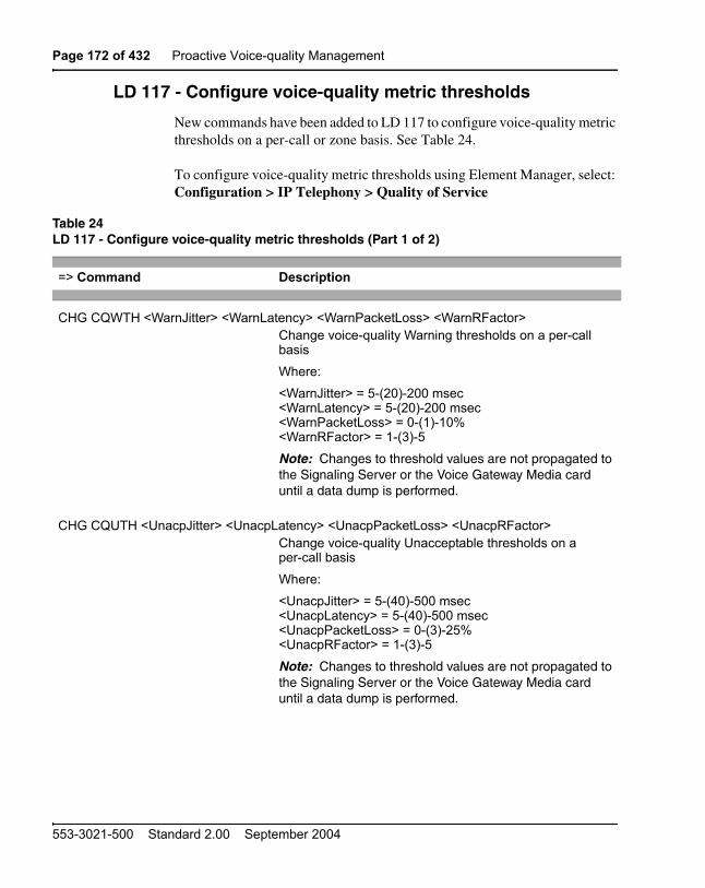
Page 172 of 432 Proactive Voice-quality Management
553-3021-500 Standard 2.00 September 2004
LD 117 - Configure voice-quality metric thresholds
New commands have been added to LD 117 to configure voice-quality metric thresholds on a per-call or zone basis. See Table 24.
To configure voice-quality metric thresholds using Element Manager, select: Configuration > IP Telephony > Quality of Service
Table 24LD 117 - Configure voice-quality metric thresholds (Part 1 of 2)
=> Command Description
CHG CQWTH <WarnJitter> <WarnLatency> <WarnPacketLoss> <WarnRFactor>Change voice-quality Warning thresholds on a per-call basis
Where:
<WarnJitter> = 5-(20)-200 msec<WarnLatency> = 5-(20)-200 msec<WarnPacketLoss> = 0-(1)-10%<WarnRFactor> = 1-(3)-5
Note: Changes to threshold values are not propagated to the Signaling Server or the Voice Gateway Media card until a data dump is performed.
CHG CQUTH <UnacpJitter> <UnacpLatency> <UnacpPacketLoss> <UnacpRFactor>Change voice-quality Unacceptable thresholds on a per-call basis
Where:
<UnacpJitter> = 5-(40)-500 msec<UnacpLatency> = 5-(40)-500 msec<UnacpPacketLoss> = 0-(3)-25%<UnacpRFactor> = 1-(3)-5
Note: Changes to threshold values are not propagated to the Signaling Server or the Voice Gateway Media card until a data dump is performed.

Proactive Voice-quality Management Page 173 of 432
Communication Server 1000M and Meridian 1 Large System Maintenance
CHG ZQWTH <WarnJitter> <WarnLatency> <WarnPacketLoss> <WarnRFactor>Change voice-quality Warning thresholds on a zone basis
Where:
<WarnJitter> = 0-(20)-100%<WarnLatency> = 0-(20)-100%<WarnPacketLoss> = 0-(20)-100%<WarnRFactor> = 0-(20)-100%
Note: Changes to threshold values are not propagated to the Signaling Server or the Voice Gateway Media card until a data dump is performed.
CHG ZQUTH <UnacpJitter> <UnacpLatency> <UnacpPacketLoss> <UnacpRFactor>Change voice-quality Unacceptable thresholds on a zone basis
Where:
<UnacpJitter> = 0-(2)-100%<UnacpLatency> = 0-(2)-100%<UnacpPacketLoss> = 0-(2)-100%<UnacpRFactor> = 0-(2)-100%
Note: Changes to threshold values are not propagated to the Signaling Server or the Voice Gateway Media card until a data dump is performed.
Table 24LD 117 - Configure voice-quality metric thresholds (Part 2 of 2)
=> Command Description

Page 174 of 432 Proactive Voice-quality Management
553-3021-500 Standard 2.00 September 2004
LD 117 - Print voice-quality metric thresholds
A new command has been added to LD 117 to print voice-quality metric thresholds. See Table 25.
LD 117 - Configure voice-quality sampling (polling)
The following command has been added to LD 117 to configure the sampling (polling) period, zone alarm-rate collection window, and the minimum number of samples to collect during the window.
To configure voice-quality sampling using Element Manager, select:
Configuration > IP Telephony > Quality of Service
Table 25LD 117 - Print voice-quality metric thresholds
=> Command Description
PRT QSTHS Print all voice-quality thresholds
Table 26LD 117 - Configure voice-quality sampling (polling)
=> Command Description
CHG SQOS <SamplePeriod> <SampleRateWindow> <MinSampleCnt>Change voice-quality sampling parameters
Where:
<SamplePeriod> = 5-(30)-60<SampleRateWindow> = 60-(300)-3600 seconds<MinSampleCnt> = 50-(100)-1000

Proactive Voice-quality Management Page 175 of 432
Communication Server 1000M and Meridian 1 Large System Maintenance
LD 117 - Configure zone alarm-notification levels
Systems that process a large number of calls potentially generate a significant number of SNMP alarms. Controlling the number of alarms by configuring zone alarm-notification levels assists in isolating voice-quality problems and reducing network traffic.
Voice-quality threshold alarms are examined for their severity relative to the alarm notification level settings. If the voice-quality threshold alarm severity exceeds the configured notification level, it generates an SNMP alarm. Otherwise it is suppressed.
Voice-quality threshold alarm notification levels can be set on a zone-by-zone basis so that some bandwidth zones can be monitored for all alarms and other zones report only serious voice-quality problems. Alarm notification levels are defined in Table 27: “Voice-quality threshold alarm notification levels” on page 175.
Table 27Voice-quality threshold alarm notification levels (Part 1 of 4)
Level Description Alarms
0 All voice-quality alarms are suppressed
None
1 Allow zone-based Unacceptable alarms
QOS0017
QOS0018
QOS0019
QOS0020
QOS0021

Page 176 of 432 Proactive Voice-quality Management
553-3021-500 Standard 2.00 September 2004
2 Allow all of the above PLUS zone-based Warning alarms
All of the above PLUS
QOS0012
QOS0013
QOS0014
QOS0015
QOS0016
Table 27Voice-quality threshold alarm notification levels (Part 2 of 4)
Level Description Alarms

Proactive Voice-quality Management Page 177 of 432
Communication Server 1000M and Meridian 1 Large System Maintenance
3 Allow all of the above PLUS per-call Unacceptable alarms
All of the above PLUS
QOS0007
QOS0008
QOS0009
QOS0010
QOS0011
QOS0021
QOS0032
QOS0033
QOS0036
QOS0037
Table 27Voice-quality threshold alarm notification levels (Part 3 of 4)
Level Description Alarms

Page 178 of 432 Proactive Voice-quality Management
553-3021-500 Standard 2.00 September 2004
4 Allow all of the above PLUS per-call Warning alarms
All of the above PLUS
QOS0001
QOS0002
QOS0003
QOS0005
QOS0006
QOS0018
QOS0019
QOS0022
QOS0023
QOS0024
QOS0025
QOS0026
QOS0027
Table 27Voice-quality threshold alarm notification levels (Part 4 of 4)
Level Description Alarms
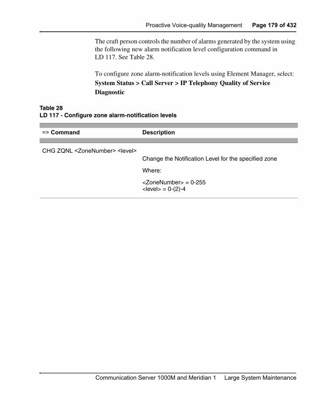
Proactive Voice-quality Management Page 179 of 432
Communication Server 1000M and Meridian 1 Large System Maintenance
The craft person controls the number of alarms generated by the system using the following new alarm notification level configuration command in LD 117. See Table 28.
To configure zone alarm-notification levels using Element Manager, select:
System Status > Call Server > IP Telephony Quality of Service Diagnostic
Table 28LD 117 - Configure zone alarm-notification levels
=> Command Description
CHG ZQNL <ZoneNumber> <level>Change the Notification Level for the specified zone
Where:
<ZoneNumber> = 0-255<level> = 0-(2)-4

Page 180 of 432 Proactive Voice-quality Management
553-3021-500 Standard 2.00 September 2004
LD 117 - Print zone alarm-notification levels
The following command has been added to LD 117 to print zone alarm-notification levels. See Table 28.
New voice-quality alarmsThis feature introduces new Warning and Unacceptable voice-quality alarms. The alarms are defined on a per-call basis or zone basis. For detailed information on QoS alarms, see What’s New for Communication Server 1000 Release 4.0 (553-3001-015).
Table 29LD 117 - Print zone alarm-notification levels
=> Command Description
PRT ZQNL <ZoneNumber> Print the Notification Level for the specified zone
Where:
<ZoneNumber> = 0-255

Proactive Voice-quality Management Page 181 of 432
Communication Server 1000M and Meridian 1 Large System Maintenance
Diagnosing and isolating voice-quality problemsNew network diagnostic utilities are accessible on IP Phones to isolate voice-quality problems. The diagnostic utilities can be run directly from the IP Phone itself, or remotely through a CLI.
Ping and Traceroute
The administrator can execute the Ping or Traceroute command from a specific endpoint with any arbitrary destination, typically another endpoint or Signaling Server.
IP Networking statistics
The administrator can view information on the packets sent, packets received, broadcast packets received, multicast packets received, incoming packets discarded, and outgoing packets discarded.
Ethernet statistics
The administrator can view ethernet statistics (for example, number of collisions, VLAN ID, speed and duplex) for the IP Phone on a particular endpoint. The exact statistics will depend on what is available from the IP Phone for the specific endpoint.
UNISTIM/RUDP statistics
The administrator can view RUDP statistics (for example, number of messages sent, received, retries, resets, and uptime) for the IP Phones.
Real time Transport Protocol statistics
The administrator can view RTP/RTCP QoS metrics (for example, packet loss, jitter, and so on) while a call is in progress.
DHCP
The administrator can view DHCP settings (for example, IP address, S1, S2, and S4 addresses) for each IP Phone.
For detailed information on network diagnostic utilities, refer to IP Phones: Description, Installation, and Operation (553-3001-368)

Page 182 of 432 Proactive Voice-quality Management
553-3021-500 Standard 2.00 September 2004
SNMP interfaceA new SNMP interface has been added to the traffic reporting system so that OTM, or any third-party system, can have a simple, standards-based interface into the system traffic reports.
For details on the new SNMP interface, refer to Simple Network Management Protocol: Description and Maintenance (553-3001-519).
Heterogeneous environmentsIn a heterogeneous environment, with a mixture of Nortel Networks equipment and third-party equipment, voice-quality monitoring, detection, and alarming are performed only on IP endpoints that have voice-quality monitoring capabilities.
For information on IP endpoints and their voice-quality capabilities in the system, refer to Table 30.
Table 30IP Endpoint and voice-quality capabilities (Part 1 of 2)
Endpoint type Voice-quality monitoring operation
Phase 0/1 IP Phones Detects jitter, packet loss, and latency (when the far end is RTCP-compliant) threshold violations.
Threshold violations are detected by polling.
Phase 2 IP Phones without PVQM package Detects jitter, packet loss, and latency (when the far end is RTCP-compliant) threshold violations.
Threshold violations are detected asynchronously by the IP Phone.

Proactive Voice-quality Management Page 183 of 432
Communication Server 1000M and Meridian 1 Large System Maintenance
Phase 2 IP Phones with PVQM package Detects jitter, packet loss, and latency (when the far end is RTCP-compliant) and R-Value threshold violations.
Threshold violations are detected asynchronously by the IP Phone.
IP Softphone 2050 Detects jitter, packet loss, and latency (when the far end is RTCP-Compliant) threshold violations.
Threshold violations are detected by polling.
CS 1000 and Meridian 1 systems with Voice Gateway Media Cards running IP Line 4.0
Detects jitter and packet loss threshold violations.
Threshold violations are detected by polling.
Third-party Gateway Not supported
Table 30IP Endpoint and voice-quality capabilities (Part 2 of 2)
Endpoint type Voice-quality monitoring operation

Page 184 of 432 Proactive Voice-quality Management
553-3021-500 Standard 2.00 September 2004

Page 185 of 432
Communication Server 1000M and Meridian 1 Large System Maintenance
192
pbxLink connection failure detection and status reporting enhancement
ContentsThis section contains information on the following topics:
Introduction . . . . . . . . . . . . . . . . . . . . . . . . . . . . . . . . . . . . . . . . . . . . . . 185
pbxLink connection failure detection . . . . . . . . . . . . . . . . . . . . . . . . . . 186Displaying pbxLink information . . . . . . . . . . . . . . . . . . . . . . . . . . . 186
LD 117 STAT SERV enhancement . . . . . . . . . . . . . . . . . . . . . . . . . . . 186pbxLink information. . . . . . . . . . . . . . . . . . . . . . . . . . . . . . . . . . . . . 187Application information . . . . . . . . . . . . . . . . . . . . . . . . . . . . . . . . . . 187
IntroductionThe pbxLink connection failure detection and status reporting enhancement provides the following functionality:
• The pbxLink connection failure detection provides a means of detecting the link status of Signaling Servers and Voice Gateway Media Cards. An alarm is generated if the pbxLink is not detected after a warm or cold start of the Call Server.
• The status reporting enhancement applies to the STAT SERV command in LD 117. This command has been enhanced to display the link status of the Signaling Server and Voice Gateway Media Cards that were configured to connect to the system. As well, the display provides information about the applications running on the Signaling Server and Voice Gateway Media Cards.

Page 186 of 432 pbxLink connection failure detection and status reporting enhancement
553-3021-500 Standard 2.00 September 2004
pbxLink connection failure detectionThe Call Server monitors the pbxLink.
The Call Server maintains a list of all known registered elements (Signaling Servers and Voice Gateway Media Cards). When a Call Server is booted, it has a 5-minute delay to enable these known elements to re-establish contact with the Call Server.
If a known element fails to register with the Call Server, an ELAN0028 alarm is generated.
If an unknown Signaling Server or Voice Gateway Media Card registers with the Call Server, an ELAN0029 alarm is generated.
Displaying pbxLink information
Element Manager
For a CS 1000S And CS 1000M, use the Element Manager System Status > Call Server > IP Telephony Services Management page to display the pbxLink information.
CLI
For a Meridian 1 system, use the LD 117 STAT SERV command at the CLI of the Call Server to display the pbxLink information.
LD 117 STAT SERV enhancementThe suite of STAT SERV (Stat Services) commands enables a technician to display link status information for elements that are registered to a Call Server.
STAT SERV can provide consolidated link status information by application type, IP address, host name, and IP Telephony node ID.

pbxLink connection failure detection and status reporting enhancement Page 187 of 432
Communication Server 1000M and Meridian 1 Large System Maintenance
Prior to CS 1000 Release 4.0, STAT SERV status information included the following:
• node ID
• host name
• IP address
• element role
• platform type
• enabled applications
• registered/unregistered endpoints, such as IP Phones and Voice Gateway Media Cards
In CS 1000 Release 4.0, the STAT SERV command has been enhanced to provide information about the pbxLink and enabled applications.
pbxLink information
The STAT SERV command provides the following pbxLink information:
• the time the pbxLink was last established
• the time the pbxLink was lost, if previously established
• the time the pbxLink last attempted to establish a connection, if the pbxLink failed to establish
Application information
If an active link to an element is established, the Call Server obtains information about the applications running on the element.
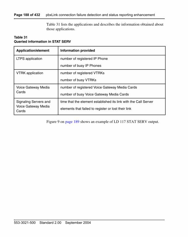
Page 188 of 432 pbxLink connection failure detection and status reporting enhancement
553-3021-500 Standard 2.00 September 2004
Table 31 lists the applications and describes the information obtained about those applications.
Figure 9 on page 189 shows an example of LD 117 STAT SERV output.
Table 31Queried information in STAT SERV
Application/element Information provided
LTPS application number of registered IP Phone
number of busy IP Phones
VTRK application number of registered VTRKs
number of busy VTRKs
Voice Gateway Media Cards
number of registered Voice Gateway Media Cards
number of busy Voice Gateway Media Cards
Signaling Servers and Voice Gateway Media Cards
time that the element established its link with the Call Server
elements that failed to register or lost their link

pbxLink connection failure detection and status reporting enhancement Page 189 of 432
Communication Server 1000M and Meridian 1 Large System Maintenance
Figure 9Sample LD 117 STAT SERV output
Commands
STAT SERV IP
TYPE
APP
NAME
NODE
xx.xx.xx.xx
xx.xx.xx
xx.xx
xx
SRV
APPS
HOSTNAME
NODE_ID
Response NODE HOSTNAME ELANIP LDR SRV APPS PBXLINK PBXLINK PBXLINK CONNECTID ID STATE DATE TIME 909 vxTarget 47.11.216.126 YES SMC LTPS LINK UP 5/06/2003 22:51:06 0x200a2128 sets: [reg - 0002] [busy - 0000] vgws: [reg - 0020] [busy - 0002] 999 IPService 47.11.216.141 N/A SS LTPS LINK UP 5/06/2003 22:51:06 0x200a2128 VTRK Sets: [reg - 0302] [busy - 0056] VTRK: [reg - 0050] [busy - 0015] 999 IPService 47.11.216.141 YES SS LTPS LINK UP 5/06/2003 22:51:06 0x200a2128 VTRK Sets: [reg - 0302] [busy - 0056] VTRK: [reg - 0050] [busy - 0015] 999 vxTarget 47.11.216.143 NO ITGP LTPS INV CONN 5/06/2003 23:18:08 0x0 999 vxTarget 47.11.216.144 NO ITGP LTPS FAILED 5/06/2003 22:51:06 0x0

Page 190 of 432 pbxLink connection failure detection and status reporting enhancement
553-3021-500 Standard 2.00 September 2004
Table 32 lists the descriptions for the fields in the STAT SERV response.
Table 32STAT SERV response fields and description (Part 1 of 3)
STAT SERV response field Description
NODE ID Identifies the related node.
Value is a number from 0 – 9999.
HOSTNAME Identifies the alias that the host has been given by the system.
Value is a string.
ELANIP Identifies the element’s IP connection to the Call Server.
Value is an IP address.
LDR Specifies if the element is the Leader for the related node.
Value is YES or NO.
SRV Specifies the element type.
Values are:
• SMC – Media Card 32-port card
• ITGP – ITG-P 24-port card
• SS – Signaling Server
APPS Specifies the application running on the element.
Values are:
• LTPS
• VTRK
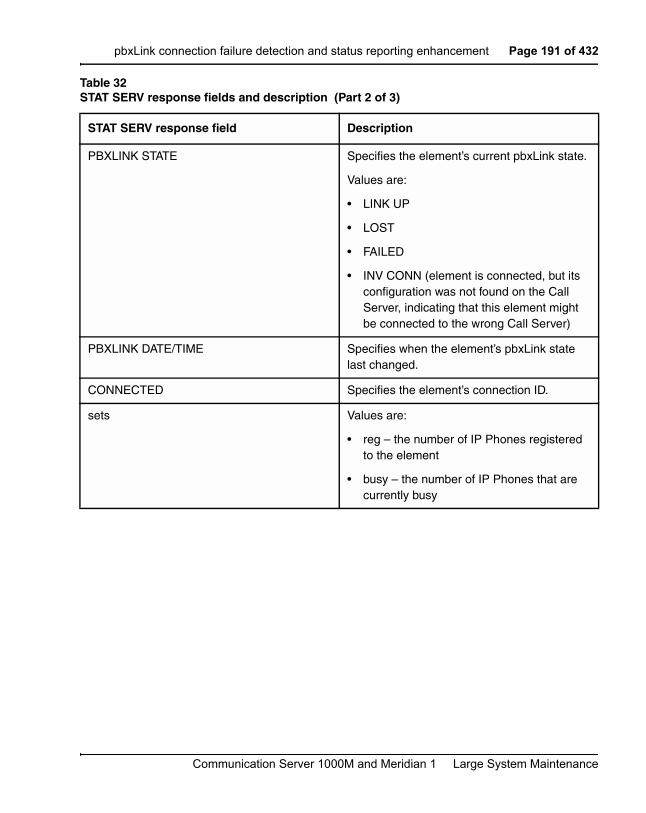
pbxLink connection failure detection and status reporting enhancement Page 191 of 432
Communication Server 1000M and Meridian 1 Large System Maintenance
PBXLINK STATE Specifies the element’s current pbxLink state.
Values are:
• LINK UP
• LOST
• FAILED
• INV CONN (element is connected, but its configuration was not found on the Call Server, indicating that this element might be connected to the wrong Call Server)
PBXLINK DATE/TIME Specifies when the element’s pbxLink state last changed.
CONNECTED Specifies the element’s connection ID.
sets Values are:
• reg – the number of IP Phones registered to the element
• busy – the number of IP Phones that are currently busy
Table 32STAT SERV response fields and description (Part 2 of 3)
STAT SERV response field Description

Page 192 of 432 pbxLink connection failure detection and status reporting enhancement
553-3021-500 Standard 2.00 September 2004
vgws Values are:
• reg – how many voice gateways (DSP resources) are configured on the element
• busy – how many voice gateways (DSP resources) are active/busy on the element
VTRK Values are:
• reg – how many VTRK channels are configured on the element
• busy – how many VTRK channels are active/busy on the element
Table 32STAT SERV response fields and description (Part 3 of 3)
STAT SERV response field Description
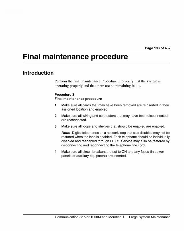
Page 193 of 432
Communication Server 1000M and Meridian 1 Large System Maintenance
196
Final maintenance procedure
IntroductionPerform the final maintenance Procedure 3 to verify that the system is operating properly and that there are no remaining faults.
Procedure 3Final maintenance procedure
1 Make sure all cards that may have been removed are reinserted in their assigned location and enabled.
2 Make sure all wiring and connectors that may have been disconnected are reconnected.
3 Make sure all loops and shelves that should be enabled are enabled.
Note: Digital telephones on a network loop that was disabled may not be restored when the loop is enabled. Each telephone should be individually disabled and reenabled through LD 32. Service may also be restored by disconnecting and reconnecting the telephone line cord.
4 Make sure all circuit breakers are set to ON and any fuses (in power panels or auxiliary equipment) are inserted.

Page 194 of 432 Final maintenance procedure
553-3021-500 Standard 2.00 September 2004
5 Clear fault indicators by entering:
LD 35 or LD 135
To clear the maintenance display in a single CPU system, enter:
CDSP
To clear the maintenance display in a dual CPU system, clear the display on one CPU by entering:
CDSP
Test the CPU by entering:
TCPU (LD 35), or
TEST CPU (LD 135)
If the response is “OK,” switch CPUs by entering:
SCPU
Clear the display on the other CPU by entering:
CDSP
To clear a major alarm indication and restore Power Fail Transfer Units (PFTUs) to normal operation, enter:
CMAJ
To clear a minor alarm indication from all attendant consoles, enter:
CMIN ALL
6 Set the midnight routine to run after you log out of the system with:
MIDN
End the session in LD 35 or LD 135 and log out of the system:
****LOGO (The midnight routine will now run.)
7 Check system messages produced when the midnight routine runs. Clear any faults indicated.

Final maintenance procedure Page 195 of 432
Communication Server 1000M and Meridian 1 Large System Maintenance
8 If there was a sysload (reload) while you were clearing a fault, reset the correct time and date by entering:
LD 2STAD (day) (month) (year) (hour) (minute) (second)
Check the time and date you entered:
TTAD
End the session in LD 2 and log out of the system:
****LOGO
9 Replace any covers you removed from modules.
10 Tag defective equipment with a description of the fault and return it to a repair center.

Page 196 of 432 Final maintenance procedure
553-3021-500 Standard 2.00 September 2004

Page 197 of 432
Communication Server 1000M and Meridian 1 Large System Maintenance
208
Software maintenance tools
ContentsThis section contains information on the following topics:
Diagnostic programs . . . . . . . . . . . . . . . . . . . . . . . . . . . . . . . . . . . . . . . 197
System features . . . . . . . . . . . . . . . . . . . . . . . . . . . . . . . . . . . . . . . . . . . 202
History file feature . . . . . . . . . . . . . . . . . . . . . . . . . . . . . . . . . . . . . . . . 203
Interactive diagnostics. . . . . . . . . . . . . . . . . . . . . . . . . . . . . . . . . . . . . . 204
Diagnostic programsDiagnostic software programs monitor system operations, detect faults, and clear faults. Some programs run continuously; some are scheduled.
Diagnostic programs are resident or non-resident. Resident programs, such as the Error Monitor and Resident Trunk Diagnostic, are always present in system memory. Non-resident programs, such as the Input/Output Diagnostic and Common Equipment Diagnostic, are used as Midnight and Background Routines or for interactive diagnostics. Non-resident programs are loaded from the system disk and are run as scheduled or upon request.
Non-resident programs are called overlay programs or loads. They are identified by a title and a number preceded by the mnemonic for load (for example, Trunk Diagnostic—LD 36).
See Software Input/Output: Administration (553-3001-311) for detailed information on all diagnostic programs.

Page 198 of 432 Software maintenance tools
553-3021-500 Standard 2.00 September 2004
Error Monitor
The Error Monitor is a resident program that continuously tracks call processing. The Error Monitor generates system messages if it detects invalid or incorrectly formatted call-processing information.
System messages generated by the Error Monitor are preceded by the mnemonic ERR, which usually indicates hardware faults, or the mnemonic BUG, which usually indicates software problems. With prompt ERRM in the Configuration Record (LD 17), you can instruct the system to print or not print ERR or BUG messages.
Refer to Software Input/Output: System Messages (553-3001-411) for help in interpreting system messages, including ERR and BUG.
Initialize Program
The Initialize Program momentarily interrupts call processing as it clears common equipment faults. It then rebuilds call-dependent data and generates system messages, with the mnemonic INI, that indicate the status of the system. This process is called an initialization.
Through an initialization, you can download firmware from the CPU to superloop network cards and controller cards. Call processing is interrupted for an additional amount of time during this process.
You can activate an initialization by pressing the manual initialize (Man Int) button on the following:
• NT6D66, NT9D19, NT5D10, or NT5D03 Call Processor Card
An initialization always occurs automatically after the System Loader program runs. An initialization often occurs when a software or firmware fault is detected and when a common equipment hardware fault is detected.
Midnight and Background Routines
In the Configuration Record (LD 17), you can select the overlay programs that will run in the Midnight Routine and Background Routine. These routines automatically perform maintenance checks. Programs included in the
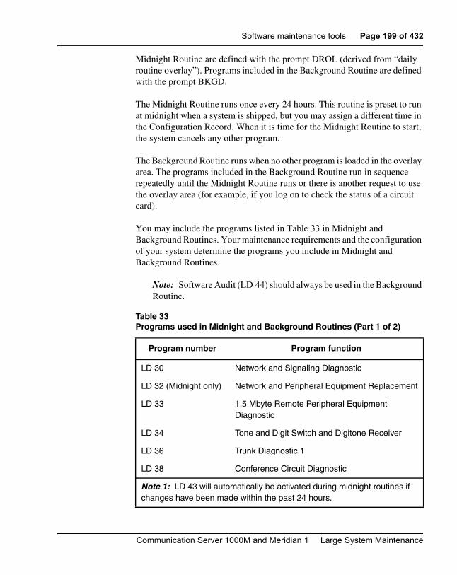
Software maintenance tools Page 199 of 432
Communication Server 1000M and Meridian 1 Large System Maintenance
Midnight Routine are defined with the prompt DROL (derived from “daily routine overlay”). Programs included in the Background Routine are defined with the prompt BKGD.
The Midnight Routine runs once every 24 hours. This routine is preset to run at midnight when a system is shipped, but you may assign a different time in the Configuration Record. When it is time for the Midnight Routine to start, the system cancels any other program.
The Background Routine runs when no other program is loaded in the overlay area. The programs included in the Background Routine run in sequence repeatedly until the Midnight Routine runs or there is another request to use the overlay area (for example, if you log on to check the status of a circuit card).
You may include the programs listed in Table 33 in Midnight and Background Routines. Your maintenance requirements and the configuration of your system determine the programs you include in Midnight and Background Routines.
Note: Software Audit (LD 44) should always be used in the Background Routine.
Table 33Programs used in Midnight and Background Routines (Part 1 of 2)
Program number Program function
LD 30 Network and Signaling Diagnostic
LD 32 (Midnight only) Network and Peripheral Equipment Replacement
LD 33 1.5 Mbyte Remote Peripheral Equipment Diagnostic
LD 34 Tone and Digit Switch and Digitone Receiver
LD 36 Trunk Diagnostic 1
LD 38 Conference Circuit Diagnostic
Note 1: LD 43 will automatically be activated during midnight routines if changes have been made within the past 24 hours.
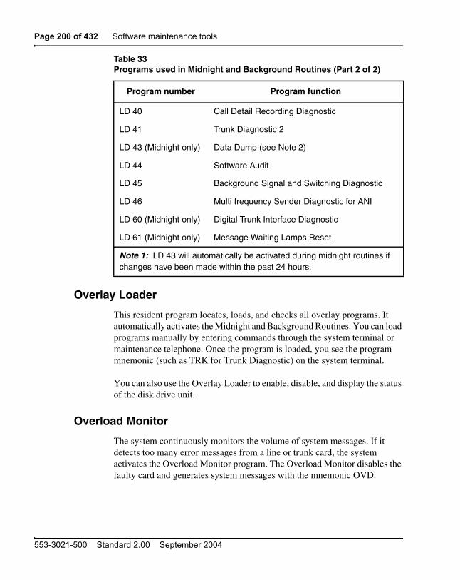
Page 200 of 432 Software maintenance tools
553-3021-500 Standard 2.00 September 2004
Overlay Loader
This resident program locates, loads, and checks all overlay programs. It automatically activates the Midnight and Background Routines. You can load programs manually by entering commands through the system terminal or maintenance telephone. Once the program is loaded, you see the program mnemonic (such as TRK for Trunk Diagnostic) on the system terminal.
You can also use the Overlay Loader to enable, disable, and display the status of the disk drive unit.
Overload Monitor
The system continuously monitors the volume of system messages. If it detects too many error messages from a line or trunk card, the system activates the Overload Monitor program. The Overload Monitor disables the faulty card and generates system messages with the mnemonic OVD.
LD 40 Call Detail Recording Diagnostic
LD 41 Trunk Diagnostic 2
LD 43 (Midnight only) Data Dump (see Note 2)
LD 44 Software Audit
LD 45 Background Signal and Switching Diagnostic
LD 46 Multi frequency Sender Diagnostic for ANI
LD 60 (Midnight only) Digital Trunk Interface Diagnostic
LD 61 (Midnight only) Message Waiting Lamps Reset
Table 33Programs used in Midnight and Background Routines (Part 2 of 2)
Program number Program function
Note 1: LD 43 will automatically be activated during midnight routines if changes have been made within the past 24 hours.

Software maintenance tools Page 201 of 432
Communication Server 1000M and Meridian 1 Large System Maintenance
Refer to Software Input/Output: System Messages (553-3001-411) for help in interpreting system messages.
Resident Trunk Diagnostic
This program automatically monitors all trunk calls and records apparent faults on each trunk. If the number of faults on a trunk exceeds the threshold for that trunk, the program generates a system message identifying the trunk and the type of fault.
A failure on a trunk may keep the trunk from detecting incoming calls. The threshold mechanism cannot detect such a failure, so this program also records how many days it has been since each trunk received an incoming call. If you suspect some incoming calls are not being processed, you can use the command LMAX in Trunk Diagnostic 1 (LD 36) to identify the trunk with the maximum idle days.
System Loader
The System Loader program loads all call-processing programs and data and starts memory-checking diagnostics. After all required programs and data have been loaded and all checks performed, the System Loader is erased from system memory, the Initialize Program runs, and normal call processing begins. This process is called a sysload or system reload.
The System Loader operates automatically on system power up or if a common equipment or power fault destroys information in the system memory. For maintenance purposes, you generally activate this program only if call processing has stopped.
Page 202 of 432 Software maintenance tools
553-3021-500 Standard 2.00 September 2004
You can start a sysload manually by pressing the reload (Rld) button on the following:
• NT6D66, NT9D19, NT5D10, or NT5D03 Call Processor Card (simultaneously press both buttons)
To minimize sysload time, you can enable the Short Memory Test capability in LD 17 (prompt SMEM). If you enable the test, only one pass of memory testing is performed on a normal reload. If any subsequent system failure causes an automatic reload, the full six-pass Memory Test is performed on all system memory.
System featuresWhen the system receives a system reload signal, the sysload occurs in two to five minutes, depending on the size of the customer database. During the sysload, the system performs a core shelf test, which includes self-tests on the CP and the IOP part of the IOP/CMDU. The results of the self-tests are displayed on the liquid crystal display (LCD) on the CP card, the hex display on the IODU/C card, and the system terminal. On the other core cards, the LED blinks three times after a successful test.
The system typically performs an initialization in under 90 seconds. You can manually initialize only the active core side.
The overlays reside in dynamic random access memory (DRAM) after they are loaded from the hard disk during an initial software load (software is shipped on redundant hard disks). Since they are always in resident memory, the overlays can be loaded quickly.
The system can diagnose faults in field replaceable units for all core hardware, including cables. In case of a failure, a message in a natural
CAUTIONDuring a sysload active calls are not disconnected and the system goes into an emergency line transfer state. Activate the System Loader only if you are specifically instructed to do so in Nortel Networks Publications.

Software maintenance tools Page 203 of 432
Communication Server 1000M and Meridian 1 Large System Maintenance
language (such as English) appears on the system terminal and on the liquid crystal display (LCD) on the CP card.
If there is a hardware fault, the system attempts a recovery. In the case of a redundant hardware failure, under certain conditions the system will attempt a graceful switchover to the core side without the failure.
Remote operation capabilities include remote access to both Core Modules or Core/Network Modules; the ability to sysload, initialize, or put the system in a split mode; and the ability to upload and download the customer database. You can access the core complex in each Core Module or Core/Network Module through the I/O ports on the CP cards.
History file featureIf you have a printer connected to the system, each system message is printed as it is received. If you do not have a printer connected, you can use the History File to store a limited number of system messages in protected memory. The contents of the file may then be printed on demand using Print Routine 3 (LD 22).
The messages stored are specified on a system basis and can be one or more of the following types:
• customer service changes (CSC)
• maintenance messages (MTC)
• service changes (SCH)
• software errors (BUG)
• initialization and sysload messages (INI and SYS)
For information on selecting the messages to be stored, see Features and Services (553-3001-306). For help with interpreting system messages, refer to Software Input/Output: System Messages (553-3001-411).
The contents of the History File are erased during a sysload or if you change the History File’s length. However, because the History File is located in protected data store, the contents survive an initialization.

Page 204 of 432 Software maintenance tools
553-3021-500 Standard 2.00 September 2004
The length of the History File is set in the configuration record (LD 17) at the size prompt under the ADAN gate opener. The maximum length of the file depends on the amount of protected data store available, which in turn depends on the number of system features that require protected data store.
If the History File is full, the first messages stored are replaced by incoming messages. If this happens, the system gives a “file overflow” message at the start of a printout so you know some information has been replaced by newer messages.
Interactive diagnosticsYou can load overlay programs, including programs called maintenance routines, into memory through the system terminal or maintenance telephone. This function is performed by the Overload Loader program.
Note: The programs used in Midnight and Background Routines are also used manually as interactive diagnostic programs (see Table 33).
Maintenance routines are used interactively with a command/response format. In this format, you enter a command that tells the system to perform a specific task. The system performs the task and sends system messages indicating the status or errors back to you.
With interactive diagnostics you can do the following:
• disable, test, and enable specific equipment
• verify that a reported fault still needs to be cleared
• verify that a repair procedure has cleared a fault
All maintenance programs and commands are described in detail in Software Input/Output: Administration (553-3001-311). For help with interpreting system messages, refer to Software Input/Output: System Messages (553-3001-411).
Manual continuity tests
You can perform manual continuity tests on superloop network cards, intelligent peripheral equipment, and Basic Rate Interface (BRI) equipment.

Software maintenance tools Page 205 of 432
Communication Server 1000M and Meridian 1 Large System Maintenance
A continuity test generates a signaling pattern at one point, monitors its progress, and checks for its detection at an end point. For example, when a superloop network card sends a signal to a controller card, the continuity test verifies the following:
• the superloop network card sent the signal
• the loop carried the signal to the controller card
• the controller card received the signal
In a point-to-point continuity test, a superloop network card or a controller card can generate or detect the test pattern. In loopback tests, one card, a superloop network card, a controller card, or a multi-purpose ISDN signaling processor (MISP) card, is both the generator and the detector. Only idle timeslots are tested in any of the continuity tests.
There are two types of loopback tests for BRI equipment. In one type of test, the pattern generated by the MISP card loops back through the digital subscriber loop (DSL) interface. In the other type of test, the pattern generated by the MISP card loops back through an S/T-interface line card (SILC) or a U-interface line card (UILC), depending on which is specified. Both types of test are accessed as Test 9, but responses to the series of prompts for Test 9 determine the loopback point.
Fifteen continuity tests can run simultaneously. When a test is completed, it stops, the status is reported, and the other tests continue running. You can check the status of any test at any time. When all the tests end, the number of tests run and any failed tests are reported to the CPU. You can display the results at any time during the procedure.
There are nine continuity test configurations. You can run each test by entering a set of prompts outlined in the Background Signaling and Switching Diagnostic (LD 45). Figure 10 on page 206 shows point-to-point configurations. Figure 11 on page 207 shows loopback configurations.

Page 206 of 432 Software maintenance tools
553-3021-500 Standard 2.00 September 2004
Figure 10Manual continuity tests: point-to-point configurations
Network
Network A Network B
Network
Network
Network B
Network A
Superloop network card to controller card
TEST 1
Controller card to superloop network card Controller
Superloop network card to superloop network card
Controller
Pattern generator Pattern detector
ControllerA
ControllerB
Controller card tocontroller card
ControllerA
ControllerB
OR
553-3008
TEST 2
TEST 3
TEST 4

Software maintenance tools Page 207 of 432
Communication Server 1000M and Meridian 1 Large System Maintenance
Figure 11Manual continuity tests: loopback configurations
Pattern generator and pattern detector
553-3009
NetworkNetworkbackplane
Network Controller
Superloop network card through backplane
TEST 5
Superloop network card through controller card
TEST 6
NetworkSpecial loopback channel *
Superloop network card through special channel
TEST 8
Controller Special loopback channel *
Controller card through special channel
TEST 7
Loopback point
* Special loopback channels are used to verify the integrity of the continuity generators and detectors. Run these tests first.
MISP DSL
BRI continuity tests:— MISP card through DSL interface— MISP card through SILC or UILC bus interface
TEST 9
MISP SILC or UILC

Page 208 of 432 Software maintenance tools
553-3021-500 Standard 2.00 September 2004

Page 209 of 432
Communication Server 1000M and Meridian 1 Large System Maintenance
214
Hardware replacement guidelines
ContentsThis section contains information on the following topics:
Precautions . . . . . . . . . . . . . . . . . . . . . . . . . . . . . . . . . . . . . . . . . . . . . . 209
System cable guidelines . . . . . . . . . . . . . . . . . . . . . . . . . . . . . . . . . . . . 213
PrecautionsTo avoid personal injury and equipment damage, review the following guidelines before handling equipment.
Power equipment
There are no user-repairable components in the power system. If a power supply fails, the complete unit must be replaced. Do not disassemble a power supply under any circumstances.
DANGER OF ELECTRIC SHOCKTo avoid the danger of electric shock, be very careful when you work with power equipment and connections. Warning notices on the equipment are displayed and must be heeded.

Page 210 of 432 Hardware replacement guidelines
553-3021-500 Standard 2.00 September 2004
Circuit cards
Handle cards as follows:
• Unpack or handle cards away from electric motors, transformers, or similar machinery.
• Handle cards by the edges only. Do not touch the contacts or components.
• Set cards on a protective antistatic bag. If an antistatic bag is not available, hand-hold the card, or set it in a card cage unseated from the connectors.
• Store cards in protective packing. Do not stack cards on top of each other unless they are packaged.
To avoid card damage from static discharge, wear a properly connected antistatic wrist strap when you work on equipment. If a wrist strap is not available, regularly touch one of the bare metal strips in a module to discharge

Hardware replacement guidelines Page 211 of 432
Communication Server 1000M and Meridian 1 Large System Maintenance
static. Figure 12 shows the recommended connection points for the wrist strap and the bare metal strips you should touch.
Figure 12Static discharge points
Wrist strap connection point Bare metal strip
553-5000
Wrist strap connection point
Bare metal strip
Power supply slot
Modulefront
Modulerear

Page 212 of 432 Hardware replacement guidelines
553-3021-500 Standard 2.00 September 2004
During replacement procedures:
• Turn off the circuit breaker or switch for a module power supply before the power supply is removed or inserted.
• In AC-powered systems, capacitors in the power supply must discharge. Wait five full minutes between turning off the circuit breaker and removing the power supply from the module.
• Software disable cards, if applicable, before they are removed or inserted.
• Hardware disable cards, whenever there is an enable/disable switch, before they are removed or inserted.
• Return defective or heavily contaminated cards to a repair center. Do not try to repair or clean them.
Data disks
Follow the precautions below to avoid damaging disks:
• Handle only the hard surface; never touch the recording surface.
• Keep disks away from strong magnetic fields.
• Avoid exposing disks to extreme heat, rapid changes in temperature, or high humidity.
• Store disks in a suitable container.
To install a disk, make sure the arrow on the label is pointing up and the rounded corner is on the bottom on the right-hand side.
CAUTIONDamage to EquipmentThe disk drive can be damaged if an upside-down disk is forced into the slot. If there is significant resistance when you try to insert a disk, remove the disk and check the position.

Hardware replacement guidelines Page 213 of 432
Communication Server 1000M and Meridian 1 Large System Maintenance
System cable guidelinesTo disconnect a cable from the Core/Network Module backplane, use the P0741489 Extraction Tool provided in the rear of the module (behind the I/O safety panel).
1 Grasp the cable connector by the strain relief tab.
2 Center the longer flat edge on the angled end of the tool between the cable connector and the wall of the shroud on the right side of the cable connector.
Note: If the straight end of the tool is notched, use that end if the connector can be accessed straight-on. If you must angle the tool at all, use the angled end.
3 Gently insert the extraction tool and gradually apply pressure while gently rocking the cable connector up and down.
4 Stop applying pressure as soon as the detent of the cable connector comes loose from the shroud.
5 Slowly remove the extraction tool and the cable connector.
CAUTIONDamage to EquipmentYou must use the P0741489 Extraction Tool to disconnect cables from the backplane shrouds in the NT5D21 Core/Network Module. Follow the procedure below to avoid bending or breaking pins when removing cable connectors from the backplane shrouds. Do not insert the extraction tool unless the cable connector is locked into the shroud. Do not force the extraction tool deeper than the detent on the cable connector.

Page 214 of 432 Hardware replacement guidelines
553-3021-500 Standard 2.00 September 2004
Before you connect cables to the backplane, visually inspect the backplane shroud connectors to make sure there are no bent pins. To connect cables:
1 Orient the cable connector so the strain relief paddle is to the right.
2 Partially insert the cable connector so its guides mate to the corresponding backplane connector.
3 Apply a small amount of pressure to push the cable connector straight into the backplane connector. You will feel a detent click when the connector seats.
CAUTIONDamage to EquipmentPins may be bent or broken if you try to insert the cable connector at an angle. Do not push the connector in any further after you hear the detent click.

Page 215 of 432
Communication Server 1000M and Meridian 1 Large System Maintenance
236
Hardware maintenance tools
ContentsThis section contains information on the following topics:
Overview . . . . . . . . . . . . . . . . . . . . . . . . . . . . . . . . . . . . . . . . . . . . . . . . 215
Circuit card features . . . . . . . . . . . . . . . . . . . . . . . . . . . . . . . . . . . . . . . 216
CPU controls . . . . . . . . . . . . . . . . . . . . . . . . . . . . . . . . . . . . . . . . . . . . . 223
System alarms . . . . . . . . . . . . . . . . . . . . . . . . . . . . . . . . . . . . . . . . . . . . 227
System monitor indicators. . . . . . . . . . . . . . . . . . . . . . . . . . . . . . . . . . . 229
OverviewThere are fault indicators and hardware features that help you perform maintenance tasks (particularly identifying and clearing faults). These maintenance tools include the following:
• circuit card features that include card level tests and status indicators
• CPU controls that allow you to control common equipment functions
• system alarms that categorize the severity of a system failure
• system monitor indicators that identify power and temperature faults

Page 216 of 432 Hardware maintenance tools
553-3021-500 Standard 2.00 September 2004
Circuit card features
Card test
A card test checks to see that a card is working correctly. Many cards perform a self-test on power-up. You can also force card-level tests through software commands.
When intelligent peripheral cards or network card share installed, the red LED on the faceplate remains lit for two to five seconds while a self-test runs. (The time required for the self-test depends on the type of card.) If the test is successful, the LED flashes three times and remains lit until the card’s software is configured and enabled, and then the LED goes out. If the LED does not follow the pattern described or operates in any other manner (such as continually flashing or remaining weakly lit), the card should be replaced.
When Core common control cards are installed, a self-test runs. If the self-test is successful, the LED flashes three times, then goes out

Hardware maintenance tools Page 217 of 432
Communication Server 1000M and Meridian 1 Large System Maintenance
Enable/disable switch
Some cards have a switch on the faceplate that enables or disables the hardware for that card.
When you remove a card, whenever possible disable the software; then, disable the hardware by setting the switch to Dis.
Hardware disable a card (set the switch to Dis) before you install it. After the card is locked into position, set the switch to Enb; then enable the card in software. Software disable and enable cards as described in the Software Input/Output: Administration (553-3001-311).
Figure 13 on page 218 shows the typical location of an Enable/Disable (ENB/DIS) switch.
LED
Many cards have one or more light emitting diodes (LEDs) on the faceplate. The LED gives a visual indication of the status of the card or of a unit on a card.
When a green LED is steadily lit, it indicates the card is operating normally. When a green LED is off, it indicates the card is disabled or faulty.
When a red LED is steadily lit, it indicates the card, or a unit on it, is disabled or faulty or unequipped. When a red LED is off and power is available to the card, it indicates the card is operating normally.
Note 1: The shape of the LED (some are round and some are rectangular) does not indicate a different function.
Note 2: The red LEDs on the NT6D65 Core to Network Interface (CNI) Cards are lit when the associated Core is inactive. This is normal operation.

Page 218 of 432 Hardware maintenance tools
553-3021-500 Standard 2.00 September 2004
Figure 13Sample enable/disable switch
553-3003
NT
Enable/Disableswitch
ENB
DIS

Hardware maintenance tools Page 219 of 432
Communication Server 1000M and Meridian 1 Large System Maintenance
Table 34 gives two examples of LED indications.
Figure 14 on page 220 shows the location of the LED on the faceplate of an Intelligent Peripheral line card.
Maintenance display code
Maintenance displays are located on the faceplate of some circuit cards. A hexadecimal code is displayed. Interpretations of the maintenance display codes are listed under “HEX” in the Software Input/Output: System Messages (553-3001-411) You should examine previous codes, system messages, and visual indicators with any current maintenance display codes to properly analyze faults.
The maintenance display on the Call Processor Card (NT6D66, NT9D19, NT5D10 or NT5D03) shows two lines of information with up to 16 characters per line. The hexadecimal code and its definition are shown on the display.
Each new code shown on a maintenance display overwrites the one before it. However, note the following:
• All codes received on common equipment displays are recorded. You can review them by printing the History File.
• The most recent 16 codes displayed on a controller card stay in memory. You can review them and reset the counter through the Network and Signaling Diagnostic (LD 30).
• The most recent 64 displays on a CP card stay in memory. You can review the displays on the active CP card through the Core Common Equipment Diagnostic (LD 135).
Table 34Sample LED indications
Type of card LED color Status
Common equipment power supply
green LED lit = operation normal
Digital line card red LED lit = disabled or not equipped

Page 220 of 432 Hardware maintenance tools
553-3021-500 Standard 2.00 September 2004
Figure 14Sample LED indicator
553-3004
NT
LEDindicator

Hardware maintenance tools Page 221 of 432
Communication Server 1000M and Meridian 1 Large System Maintenance
Table 35 lists the cards with maintenance displays and the type of information the codes indicate on each card. Figure 15 on page 222 shows the location of the maintenance display on the faceplate of a floppy disk interface card.
Table 35Circuit cards with maintenance displays
Circuit card Display indication (for all related cards)
NT6D66, NT9D19, NT5D10, NT5D03 Call Processor Card
NT5D61 IODU/C Card
NT8D01 Controller Card
NT1P62 Fiber Controller
During normal operation, display shows self-test codes and port number on which Controller Clock is tracking
NT7R52 Remote CarrierInterface Card
During normal operation, display shows self-test codes and port number on which Controller Clock is tracking

Page 222 of 432 Hardware maintenance tools
553-3021-500 Standard 2.00 September 2004
Figure 15Sample maintenance display
553-3001
Two-digitmaintenance
display

Hardware maintenance tools Page 223 of 432
Communication Server 1000M and Meridian 1 Large System Maintenance
CPU controlsSwitches and buttons on common equipment cards allow you to control CPU activity and clear common equipment faults.
Initialize button
Pressing the manual initialize (Man Int) button associated with the active CPU starts the Initialize Program. The Initialize Program clears common equipment faults and then rebuilds call-dependent data and generates system messages indicating the status of the system. This process is called an initialization. Call processing is briefly interrupted during an initialization.
Manual initialize buttons are located on the following cards:
• The initialize button is on the NT6D66, NT9D19, NT5D10, or NT5D03 Call Processor Card.
Normal/maintenance switch
There is a normal/maintenance (Norm/Maint) switch on the Call Processor Card. Figure shows the location of the switch on the Call Processor Card. In dual CPU systems you use this switch as follows to keep the dual CPUs from switching, or trying to switch, when you are testing or replacing common equipment hardware on the inactive CPU:
• On the CPU you are not testing or replacing, set the switch to Maint. This CPU is active.
• On the CPU you are testing or replacing, set the switch to Norm. This CPU will remain inactive as long as the other CPU is set to Maint.
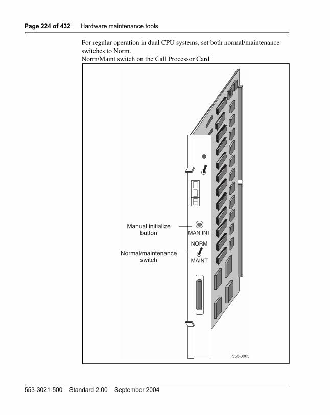
Page 224 of 432 Hardware maintenance tools
553-3021-500 Standard 2.00 September 2004
For regular operation in dual CPU systems, set both normal/maintenance switches to Norm.Norm/Maint switch on the Call Processor Card
553-3005
NT
Manual initializebutton
Normal/maintenanceswitch
MAN INT
NORM
MAINT
Hardware maintenance tools Page 225 of 432
Communication Server 1000M and Meridian 1 Large System Maintenance
Reload button
Reload (Rld or Man Rst) buttons allow you to manually activate the System Loader program. The System Loader initiates call processing and starts memory-checking diagnostics. This process is called a sysload or system reload. The reload button (Man Rst) is on the Call Processor Card.
To start a sysload, press both reload buttons simultaneously.
Figure 16 shows the location of the reload button on a QPC581 CMA Card.
CAUTIONDuring a sysload active calls are disconnected and the system goes into an emergency line transfer state. Use the reload button only if you are specifically instructed to do so in Nortel Networks Publications.

Page 226 of 432 Hardware maintenance tools
553-3021-500 Standard 2.00 September 2004
Figure 16Reload button on the changeover and memory arbitrator card
553-3006
NT
Reload buttonRLD

Hardware maintenance tools Page 227 of 432
Communication Server 1000M and Meridian 1 Large System Maintenance
System alarmsSystem alarms are based on various fault monitors and indicators. The category of the alarm—major, minor, or remote—indicates the severity of the system failure:
• A major alarm requires immediate action by the technician.
• A minor alarm requires attention, but not necessarily immediate attention, by the technician.
• A remote alarm may require attention by the technician.
Major alarms
A major alarm indicates a fault that seriously interferes with call processing. The following faults cause a major alarm:
• CPU or control bus failure
• disk system failure when attempting to load the system
• system power failure (without reserve power)
• temperature fault (excessive heat)
When there is a major alarm, the red LED at the top of the affected column lights. A major alarm also activates a display on all attendant consoles.
When a system is equipped with a power failure transfer unit, a major alarm causes designated 500/2500 telephones to connect directly to Central Office trunks; this is called a line transfer.

Page 228 of 432 Hardware maintenance tools
553-3021-500 Standard 2.00 September 2004
Minor alarms
A minor alarm indicates the system hardware or software has detected a fault requiring attention. The following faults cause a minor alarm: Automatic identification of outward dial (AIOD) trunk failure
• conference failure
• digitone receiver failure
• memory failure
• more than one fault on different line and trunk cards in one shelf (indicated on affected customer’s console only)
• network failure (indicated on affected customer’s console only)
• peripheral signaling failure
• serial data interface failure
• tone and digit switch failure
A minor alarm displays an alarm on attendant consoles in customer groups affected by the fault. (A minor alarm indication on the console is an optional feature, enabled and disabled on a customer basis through data administration procedures.)
Remote alarms
A remote alarm is an optional extension of a major alarm to another location, such as a monitoring or test center, or to an indicator, such as a light or bell. When a major alarm occurs, the system provides relay contact closure across two remote alarm lines, REMALMA and REMALMB. These lines are extended to the main distribution frame (MDF) through the system monitor to MDF cable for customer use. The relay contacts are rated at 30 V dc and 2 amps. The REMALMB line is the return or ground for the REMALMA line. Nortel Networks does not extend remote alarm lines beyond the MDF.

Hardware maintenance tools Page 229 of 432
Communication Server 1000M and Meridian 1 Large System Maintenance
System monitor indicatorsThe system monitor checks the column temperature, cooling system status, and system voltage status and controls line transfer states accordingly.
NT8D22 System Monitor
The system is equipped with the NT8D22 System Monitor, which is installed in the rear of the pedestal in each column. Table 36 lists faults monitored by this system monitor.
Note: In multiple-column systems, there is one master system monitor, located in the column with CPU 0, and multiple slave system monitors. A switch setting on each system monitor defines the master or the address of each slave.
The master system monitor checks the CPU column and periodically polls the slaves to check their status. When polled, the slaves report their status to the master. If a slave does not respond when it is polled, the master reports the address as a faulty slave.
Table 36Faults monitored by the NT8D22 System Monitor
Power faults Source
CPU condition CPU failure
Sysload (system reload)
Main power loss System input power, AC or DC
Power supply failure Common equipment power supply
Common/peripheral equipment power supply
Peripheral equipment power supply
Ringing generator
Temperature alarm Blower unit
Column temperature sensors

Page 230 of 432 Hardware maintenance tools
553-3021-500 Standard 2.00 September 2004
If a slave is removed, the master cannot communicate with higher addresses. Therefore, the master considers the removed slave and all slaves with a higher address as disabled. For example, if slave 2 is disabled, the master also reports slaves 3, 4, and up as disabled.
The system monitor reports power equipment status and faults to the CPU. (Only the master system monitor communicates with the CPU.) System messages generated by the system monitor are identified by the mnemonic PWR. Figure 17 shows the flow of messages from NT8D22 System Monitors to the system terminal.
If there is a fault, the system monitor lights the LED on the affected column.

Hardware maintenance tools Page 231 of 432
Communication Server 1000M and Meridian 1 Large System Maintenance
Figure 17NT8D22 System Monitor message flow
••
Last slavesystem monitor
553-3007
SystemCPU
Mastersystemmonitor
Systemterminal
CPU faultMain power loss
Power supply failureTemperature alarms
Fault sources to master system monitor
1st slavesystemmonitor
Fault sources to slavesystem monitor
CPU faultMain power loss
Power supply failureTemperature alarms
Serial data interface
(SDI)
Serial data interface
(SDI)

Page 232 of 432 Hardware maintenance tools
553-3021-500 Standard 2.00 September 2004
Line transfer
As an option, you can connect one or more power failure transfer units (PFTUs) to the system. Each PFTU connects up to eight designated analog (500/2500 type) telephones to Central Office trunks. If call processing stops, those analog (500/2500 type) telephones are transferred through the PFTU to the Central Office so that you still have outside connections. A line transfer occurs during the following situations:
• during a sysload (system reload)
• if there is a major power failure in a DC-powered system (as detected by the TRIP signal)
• if call processing stops because of a CPU failure
• if there is a loss of power to the column
• if there is a loss of power to the PFTU
• if the temperature in a column is too high
• if a line transfer button on the attendant console is pressed (this applies on a customer basis)
• if a line transfer switch on the PFTU is turned on
Note: If position 4 on switch 1 (SW1) is set to OFF on a system monitor, that system monitor’s column will not activate a line transfer if the temperature is too high.
Figure 18 on page 233 shows four ways multiple-column systems and PFTUs can be configured. You can configure in the following ways:
• connect all the columns in a system to a single PFTU
• connect each column to an individual PFTU
• combine connecting individual columns to individual PFTUs and multiple columns to a single PFTU
• attach additional PFTUs to a PFTU that is connected to one or multiple columns
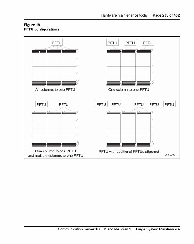
Hardware maintenance tools Page 233 of 432
Communication Server 1000M and Meridian 1 Large System Maintenance
Figure 18PFTU configurations
All columns to one PFTU One column to one PFTU
One column to one PFTUand multiple columns to one PFTU
PFTU with additional PFTUs attached553-3035
PFTU PFTU PFTU PFTU
PFTU PFTU PFTU PFTU PFTU PFTU PFTU

Page 234 of 432 Hardware maintenance tools
553-3021-500 Standard 2.00 September 2004
Main power loss
The system monitor receives status and control signals from the external power system. The system monitor then generates system messages that indicate the status of main and reserve power supplies.
You can connect a reserve (back-up) power supply to the system: either an uninterruptible power supply (UPS) for AC-powered systems or reserve batteries for DC-powered systems. If the main source of external power is lost, power to the system is maintained by the UPS or reserve batteries.
If the main power supply is lost, the system monitor generates a major alarm. The NT8D22 System Monitor also generates system messages to indicate the system is running on reserve power.
Module power supply failure
There are four types of module power supplies:
• common equipment (CE) power supply
• common/peripheral equipment (CE/PE) power supply
• Intelligent Peripheral Equipment (IPE) power supply
• ringing generator
The NT8D22 System Monitor handles complete or partial failures in a module power supply as follows:
• If the output voltage is higher than the threshold for +5 volts, the affected power supply shuts down, the column LED lights, and a system message is sent.
• If the output voltage is higher than the threshold for other than +5 volts, power for only that voltage shuts down in the affected power supply, the column LED lights, and a system message is sent.
• If the output voltage is lower than the threshold for any voltage, power for only that voltage shuts down in the affected power supply, the column LED lights, and a system message is sent.
• If the input voltage is lower than the threshold, the affected power supply shuts down and then recovers when the input level recovers.

Hardware maintenance tools Page 235 of 432
Communication Server 1000M and Meridian 1 Large System Maintenance
To help you pinpoint a power supply problem, the master NT8D22 System Monitor identifies the following:
• the column with the fault (system monitor 0–63)
• the module (0–3) in that column
• the power supply unit (1–2) in the module
Figure 19 shows the power equipment designations in a column.
Temperature alarms
Each column is cooled by a blower unit (NT8D52AB with AC power or NT8D52DD with DC power) in the pedestal. All of these systems are equipped with the NT8D22 System Monitor, which performs the following functions:
• If there is a partial or complete failure in a blower unit, the system monitor lights the column LED and generates a system message.
• If the thermostats in a column report a temperature exceeding 70 degrees C (158 degrees F), the system monitor lights the column LED, generates a system message, then, providing this condition exists for 30 seconds, shuts down power to the column in 30 seconds.
The NT8D22 System Monitor generates a system message if the air leaving the column exceeds 55 degrees C (131 degrees F). This thermal alarm may indicate a loss of air-conditioning in the room, loss of ventilation in the column, a problem with the blower unit, or a blocked air filter.

Page 236 of 432 Hardware maintenance tools
553-3021-500 Standard 2.00 September 2004
Figure 19Power equipment designations from the master NT8D22 System Monitor
553-3014
Module 3Power unit 1
Column 0System monitor 0
Module 2Power unit 1Power unit 2
Module 1Power unit 1
Module 0Power unit 1
Front of the column, covers removed

Page 237 of 432
Communication Server 1000M and Meridian 1 Large System Maintenance
238
Routine maintenance
ContentsThis section contains information on the following topics:
Pedestal air filter . . . . . . . . . . . . . . . . . . . . . . . . . . . . . . . . . . . . . . . . . . 237
DC-power battery systems . . . . . . . . . . . . . . . . . . . . . . . . . . . . . . . . . . 238
You must service batteries and air filters regularly. Follow the guidelines in this chapter to maintain batteries and air filters.
Pedestal air filterThere is an air filter in the pedestal of each column. Service the air filters once a month. For instructions on replacing the air filter, see “Replacing equipment” on page 239.
If an air filter is damaged in any way, discard it and install a new one. If a dirty air filter is not damaged, you can clean it with warm water and mild detergent. (Do not use compressed air because it may damage the filter.) When the filter is completely dry, you can reinsert it in the pedestal or store it as a spare.
Replace the battery pack every three years, even if no battery failures have occurred. For instructions on replacing the battery pack assembly, see “Replacing equipment” on page 239.

Page 238 of 432 Routine maintenance
553-3021-500 Standard 2.00 September 2004
DC-power battery systemsExternal batteries, often used with DC-powered systems, generally require regular visual inspections. They may also require charger or rectifier tests and pilot cell tests. Perform all inspections and tests according to the supplier’s instructions.
To comply with safety requirements, consult the following articles before working with any battery systems:
• Read the “Material Safety Data Sheet” that must be posted to meet Occupational Safety and Health Administration (OSHA) requirements. This article outlines appropriate reserve battery handling procedures.
• Refer to National Electric Code 645-10. This article outlines requirements that call for the installation of AC- and DC-power kill switches to battery systems in certain environments.

Page 239 of 432
Communication Server 1000M and Meridian 1 Large System Maintenance
406
Replacing equipment
Content listThis section contains information on the following topics:
Removing module covers and pedestal grills . . . . . . . . . . . . . . . . . . . . 241
NT1P61 Fiber Superloop Network Card. . . . . . . . . . . . . . . . . . . . . . . . 243
NT1P62 Fiber Peripheral Controller Card . . . . . . . . . . . . . . . . . . . . . . 245
NT4N43 cPCI Multi-Media Disk Unit . . . . . . . . . . . . . . . . . . . . . . . . . 246
NT4N65, and NT4N66 cPCI Core Network Interface Cards . . . . . . . . 258
NT4N67 and NT4N68 System Utility cards . . . . . . . . . . . . . . . . . . . . . 264
NT4N64, and A0810496 Call Processor (CP PII) card . . . . . . . . . . . . 268
NT5D10 68060 Call Processor (CP) Card . . . . . . . . . . . . . . . . . . . . . . 270
NT5D12AA Dual DTI/PRI (DDP) . . . . . . . . . . . . . . . . . . . . . . . . . . . . 278
NT5D61 Input/Output Disk Unit with CD-ROM (IODU/C) . . . . . . . . 281
NT5D61 IODU/C Security Device . . . . . . . . . . . . . . . . . . . . . . . . . . . . 288
NT5D2103 Core/Network Card Cage. . . . . . . . . . . . . . . . . . . . . . . . . . 291
NT5K09 Quad Digitone Receiver. . . . . . . . . . . . . . . . . . . . . . . . . . . . . 302
NT5K10 Dual Loop Peripheral Buffer Card. . . . . . . . . . . . . . . . . . . . . 303
NT5K1106 Enhanced Peripheral Equipment Card Cage . . . . . . . . . . . 305
NT5K21AA Extended Multi - Frequency Compelled Sender/Receiver Card . . . 308
NT6D40, NT6D41, NT6D42, Power Supply DC . . . . . . . . . . . . . . . . . 309
NT6D65 and NTRB34 Core to Network Interface Cards. . . . . . . . . . . 310
NT7D10 Power Distribution Unit DC . . . . . . . . . . . . . . . . . . . . . . . . . 313

Page 240 of 432 Replacing equipment
553-3021-500 Standard 2.00 September 2004
NT7D67CB Power Distribution Unit DC. . . . . . . . . . . . . . . . . . . . . . . 318
NT7R51 Local Carrier Interface Card . . . . . . . . . . . . . . . . . . . . . . . . . 323
NT7R52 Remote Carrier Interface Card. . . . . . . . . . . . . . . . . . . . . . . . 324
NT8D01 Controller Card . . . . . . . . . . . . . . . . . . . . . . . . . . . . . . . . . . . 325
NT8D02, NT8D03, NT8D09, NT8D14, NT8D15, NT8D16 Intelligent Peripheral Equipment Card. . . . . . . . . . . . . . . . . . . . . . . . . . . . . . . . . . 327
NT8D04 Superloop Network Card, QPC414 Network Card . . . . . . . . 330
NT8D06, NT8D21, NT8D29 Power Supply AC . . . . . . . . . . . . . . . . . 332
NT8D17 Conference/TDS Card . . . . . . . . . . . . . . . . . . . . . . . . . . . . . . 334
NT8D22 System Monitor . . . . . . . . . . . . . . . . . . . . . . . . . . . . . . . . . . . 335
NT8D41 Dual or Quad Port Serial Data Interface card . . . . . . . . . . . . 337
NT8D46AC Thermostat Harness . . . . . . . . . . . . . . . . . . . . . . . . . . . . . 339
NT8D46AM, NT8D46DC Air Probe Harness . . . . . . . . . . . . . . . . . . . 345
NT8D52AB, NT8D52DD Pedestal Blower Unit . . . . . . . . . . . . . . . . . 348
NT8D53CA Power Distribution Unit AC . . . . . . . . . . . . . . . . . . . . . . 350
NT8D56AA, NT8D56AC, NT8D57 Module Power Distribution Unit . . . . . . . . 353
NT8D3503/NT8D3507 Network Module Card Cage . . . . . . . . . . . . . 355
NT8D3703 IPE Module Card Cage . . . . . . . . . . . . . . . . . . . . . . . . . . . 363
NT9D19 68040 Call Processor (CP) Card replacement in systems equipped with NT5D61 IODU/C cards. . . . . . . . . . . . . . . . . . . . . . . . . . . . . . . . . . . . . . . . . . . . . . . . . 368
NTAG26 Extended Multi-frequency receiver . . . . . . . . . . . . . . . . . . . 373
NTAG26 Extended Multi-frequency receiver . . . . . . . . . . . . . . . . . . . 373
NTBK51AA Downloadable D-Channel Daughterboard . . . . . . . . . . . 374
FIJI Card replacement. . . . . . . . . . . . . . . . . . . . . . . . . . . . . . . . . . . . . . 378
P0699798 Air Filter . . . . . . . . . . . . . . . . . . . . . . . . . . . . . . . . . . . . . . . 381
QPC43 Peripheral Signaling Card . . . . . . . . . . . . . . . . . . . . . . . . . . . . 383
QPC441 Three-Port Extender Card . . . . . . . . . . . . . . . . . . . . . . . . . . . 385
QPC471, QPC775 Clock Controller Card . . . . . . . . . . . . . . . . . . . . . . 390
QPC477 Bus Terminating Unit. . . . . . . . . . . . . . . . . . . . . . . . . . . . . . . 393
QPC659 Dual Loop Peripheral Buffer Card. . . . . . . . . . . . . . . . . . . . . 394

Replacing equipment Page 241 of 432
Communication Server 1000M and Meridian 1 Large System Maintenance
QPC841 Serial Data Interface Card . . . . . . . . . . . . . . . . . . . . . . . . . . . 396
Removing module covers and pedestal grills
Module covers
To remove the front and rear covers from a module:
1 With a flat-blade screwdriver, turn the lock clockwise on the two locking latches (see Figure 20).
2 Simultaneously push the latches toward the center of the cover and pull the cover toward you while lifting it away from the module.
Pedestal grills
To remove the front and rear grills on the pedestal:
1 Loosen the two captive screws that secure the grill.
2 Pull the grill forward and lift it out of the base of the pedestal (see Figure 20).
Removing UK air exhaust/intake grills
Use the following procedures to remove or replace the exhaust and intake grills on United Kingdom (UK) equipment.
Air exhaust grill
The front and rear air exhaust grills are secured by Southco fasteners located underneath the front edge of the grill. Use a #1 Phillips head screwdriver and turn the fasteners 1/4-turn to release or secure the grill (see Figure 20).
DANGERModule covers are not hinged; do not let go of the cover. Lift the cover away from the module and set it out of your work area.

Page 242 of 432 Replacing equipment
553-3021-500 Standard 2.00 September 2004
Figure 20Removing the pedestal grill
Figure 21Removing air exhaust grill
553-3054
Captive screw
Captive screw
Air exhaust grill Air exhaust grillTop cap
UEM 1/4 turn fasteners
553-7375
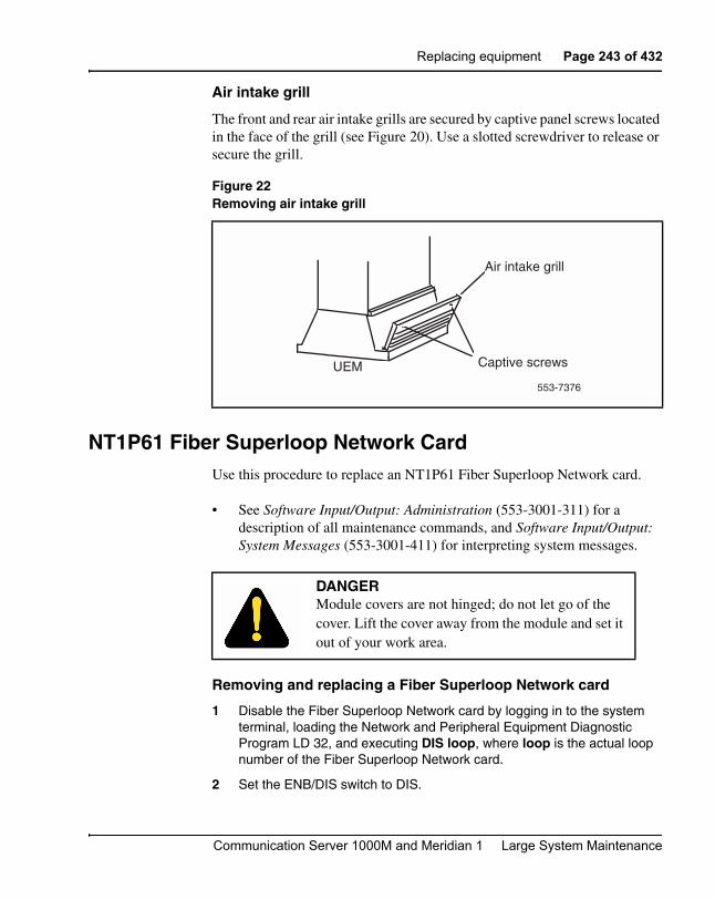
Replacing equipment Page 243 of 432
Communication Server 1000M and Meridian 1 Large System Maintenance
Air intake grill
The front and rear air intake grills are secured by captive panel screws located in the face of the grill (see Figure 20). Use a slotted screwdriver to release or secure the grill.
NT1P61 Fiber Superloop Network CardUse this procedure to replace an NT1P61 Fiber Superloop Network card.
• See Software Input/Output: Administration (553-3001-311) for a description of all maintenance commands, and Software Input/Output: System Messages (553-3001-411) for interpreting system messages.
Removing and replacing a Fiber Superloop Network card
1 Disable the Fiber Superloop Network card by logging in to the system terminal, loading the Network and Peripheral Equipment Diagnostic Program LD 32, and executing DIS loop, where loop is the actual loop number of the Fiber Superloop Network card.
2 Set the ENB/DIS switch to DIS.
Figure 22Removing air intake grill
DANGERModule covers are not hinged; do not let go of the cover. Lift the cover away from the module and set it out of your work area.
UEM Captive screws
Air intake grill
553-7376

Page 244 of 432 Replacing equipment
553-3021-500 Standard 2.00 September 2004
3 Disconnect all the Fiber-optic patchcords and the SDI/System Monitor cable from the card faceplate.
4 Unlatch the card’s locking devices by squeezing the tabs and pulling the upper locking device away from the card and pressing the lower locking device downward.
5 Pull the card out of the network module and place it into an antistatic bag away from the work area.
6 Check the replacement card and make sure that the Electro-optical packlets are already installed. If not installed, install the new packlets or remove the packlets from the faulty Fiber Superloop Network card and install them on the replacement card if you are sure that the packlets are not faulty.
7 Set the replacement card ENB/DIS switch to DIS.
8 Hold the replacement card by the card locking devices and insert it partially into the card guides in the module.
9 Pull the upper locking device away from the faceplate on the card and press the lower locking device downward and insert the card firmly into the backplane connector. Press the upper locking device firmly against the faceplate and press the lower locking device upwards to latch the card inside the module.
10 Set the ENB/DIS switch on the Fiber Superloop Network card to ENB. The Fiber Superloop Network card automatically starts the self-test.
11 Observe the red LED on the front panel during self-test. If it flashes three times and stays on, it has passed the test; go on to step 13. If it does not flash three times and then stays on, it has failed the test. Pull the card partially out of the module and reinsert it firmly into the module. If the problem persists, troubleshoot or replace the Fiber Superloop Network card.
12 Connect the SDI/System Monitor cable and the Fiber-optic patchcords to the faceplate connectors of the replacement Fiber Superloop Network card.
13 Enable the Fiber Superloop Network card by logging in to the system terminal, loading the Network and Peripheral Equipment Diagnostic Program LD 32, and executing ENLL loop, where loop is the actual loop number of the Fiber Superloop Network card.
14 Tag the defective card(s) with a description of the problem and prepare them for shipment to your equipment supplier’s repair depot.

Replacing equipment Page 245 of 432
Communication Server 1000M and Meridian 1 Large System Maintenance
NT1P62 Fiber Peripheral Controller CardUse this procedure to replace a Fiber Peripheral Controller card.
• Software Input/Output: Administration (553-3001-311) for a description of all maintenance commands, and Software Input/Output: System Messages (553-3001-411) for interpreting system messages.
Removing and replacing a Fiber Peripheral Controller card
1 Load Network and Peripheral Equipment Diagnostic Program LD 32. At the > prompt, type LD 32 and press the Enter key to access the program.
2 Type DSXP x, where x is the Fiber Peripheral Controller card, and press the Enter key to disable the card. The Fiber Peripheral Controller card is now disabled and you can remove it.
3 Disconnect all the Fiber-optic patchcords from the card faceplate.
4 Unlatch the card’s locking devices by squeezing the tabs and pulling the upper locking device away from the card and the lower locking device downwards.
5 Pull the card out of the IPE module or cabinet and place it in an antistatic bag away from the work area.
6 Check the replacement card and make sure that the Electro-optical packlets are already installed. If not installed, install the new packlets or remove the packlets from the faulty Fiber Peripheral Controller card and install them on the replacement card if you are sure the packlets are not faulty.
7 Hold the replacement card by the card locking devices and insert it partially into the card guides in the module.
DANGERModule covers are not hinged; do not let go of the cover. Lift the cover away from the module and set it out of your work area.

Page 246 of 432 Replacing equipment
553-3021-500 Standard 2.00 September 2004
8 Pull the upper locking device away from the faceplate on the card and the lower locking device downwards and insert the card firmly into the backplane connector. Press the upper locking device firmly against the faceplate and the lower locking device upwards to latch the card inside the module. The Fiber Peripheral Controller card automatically starts the self-test.
9 Observe the red LED on the front panel during self-test. If it flashes three times and stays on, it has passed the test. Go to step 11. If it does not flash three times and then stays on, it has failed the test. Pull the card partially out of the module and reinsert it firmly into the module. If the problem persists, troubleshoot or replace the Fiber Peripheral Controller card.
10 Connect the Fiber-optic patchcords to the optical connectors of the Fiber Peripheral Controller card faceplate. For a wall-mounted Fiber Remote IPE, plug the Fiber-optic span FC/PC optical connectors into the FC/PC optical connectors on the Fiber Peripheral Controller card faceplate.
11 At the prompt in the LD 32 program, type ENXP x, where x is the Fiber Peripheral Controller card, and press the Enter key to enable the card. If the uppermost red LED on the Fiber Peripheral Controller card faceplate turns off, the card is functioning correctly and is enabled. The outcome of self-test will also be indicated by LD 32 on the MMI terminal connected to the Fiber Peripheral Controller card. If the LED stays on, replace the card.
12 Tag the defective card(s) with a description of the problem and prepare them for shipment to your equipment supplier’s repair depot.
NT4N43 cPCI Multi-Media Disk UnitThe Multi-Media Disk Units (MMDUs) in the respective cores can be of any size equal to or greater than 6GB. The MMDUs do not need to be the same size since the VxWorks OS configures each MMDU to exactly 6GB, thus preserving redundancy. This feature is automatically activated during sysload.

Replacing equipment Page 247 of 432
Communication Server 1000M and Meridian 1 Large System Maintenance
Core card replacement
All cards are factory installed. If you need to replace a card, follow the guidelines below.
1 To remove a card, hold the card by the faceplate and gently pull it out of the slot.
2 To install a card, hold the card by the faceplate and gently push it into the slot until firmly seated and bolted into place.
3 Gently push forward to seat the card and lock it in place.
Never force the card into the slot. If the card gets stuck, remove it and try again.
Note: It is recommended to power down the Core Net Module when replacing a MMDU if possible. Please note that powering down the Core/Net module disables the half of the network, if assigned in the Core/Net shelf. Not all sites will easily accommodate this recommendation. Therefore, a procedure has been created to replace the MMDU without removing power from the Core/Net shelf.
4 Backup the data.
5 The MMDU to be replaced should be in the inactive core. If that is not the case, switch CPUs.
6 Use the “split” command to split the system.
7 Use "Stat CPU" to confirm the cores are split.
8 Connect terminal to the inactive side.
9 Reset the Call Processor card in the inactive side by pressing the "reset" button located on the faceplate.
10 Pay attention to the boot sequence. When the message "Press Control B to Stop" appears, press Control B to interrupt the boot sequence. The [VxWorks Boot] prompt with a flashing cursor should be on your screen. If you do not see this prompt with the flashing cursor, go back to step 9.
CAUTION WITH ESDS DEVICESTo avoid card damage from static discharge, wear a properly connected antistatic wrist strap.

Page 248 of 432 Replacing equipment
553-3021-500 Standard 2.00 September 2004
11 If possible, power down the Core/Net shelf.
12 Select the proper replacement procedure below.
Replacement procedures
Use “Procedure 1: Replace the NT4N43AA cPCI Multi-Media Disk Unit (MMDU) leaving the card cage in place” on page 248, if you have an I/O panel with an access panel and an interior cutout.
Use “Procedure 2: Replace the NT4N43AA cPCI Multi-Media Disk Unit (MMDU) by removing the card cage” on page 250, if you have an I/O panel with an access panel without an interior cutout or an I/O panel with solid metal on the left side.
Use “Procedure 3: Replace the NT4N43BA and NT4N43CA cPCI Multi-Media Disk Unit (MMDU)” on page 254,if you have an NT4N43BA or NT4N43CA cPCI Multi-Media Disk Unit (MMDU).
Procedure 1:Replace the NT4N43AA cPCI Multi-Media Disk Unit (MMDU) leaving the card cage in place
1 At the rear of the Call Processor PII (CP PII) module, remove the three cables connected to the back of the MMDU (see Figure 23 on page 257):
a. Push up the tabs and disconnect the bottom CD-ROM and Hard Drive Data Cable (NT4N92AA).
b. Push up the tabs and disconnect the middle Floppy Data Cable (NT4N93AA).
c. Squeeze the top and bottom tabs and disconnect the top Floppy, CD-ROM, and Hard Drive Power Cable (NT4N95AA).

Replacing equipment Page 249 of 432
Communication Server 1000M and Meridian 1 Large System Maintenance
2 At the front of the module, use a slotted or Phillips screwdriver to unscrew the center screws on the top and bottom of the MMDU.
Note: Some systems have MMDU screws which are captive, while some systems have MMDU screws which can be removed.
3 Use the MMDU handle to slowly pull the MMDU forward, bringing the attached cables with it.
4 Remove the MMDU unit (with the cables attached) from the card cage.
5 Remove the cables and reattach them to the new MMDU.
6 From the front of the module, bundle and feed the cables attached to the MMDU into the MMDU slot.
7 Slowly slide the MMDU three-quarters of the way into the shelf until it is supported in the shelf.
8 At the rear of the module, gently pull the attached cables through to clear the backplane edge.
9 Connect the three MMDU cables:
CAUTIONDamage to EquipmentCables are attached to the back of the MMDU.
CAUTIONDamage to EquipmentWhen you feed the cables into the MMDU slot, be very careful that the cables do not pinch or snag on either side.
CAUTIONDamage to EquipmentBe careful not to pull any cables too hard or you may dislodge them from the unit. If any cables become dislodged, remove the MMDU from the front of the module and reattach the cables.

Page 250 of 432 Replacing equipment
553-3021-500 Standard 2.00 September 2004
a. Connect the longer of the two ribbon cables to the connector labeled Floppy Drive.
b. Connect the shorter of the two ribbon cables to the slot (below the Floppy Drive) labeled IDE Secondary Channel.
c. Open the tabs and push the connector to attach the third cable to the top cable connection labeled +12, GND,GND,VCC.
10 From the front of the module, carefully slide the MMDU the remainder of the way into the slot.
11 Use a slotted or Phillips screwdriver to secure the center screws on the top and bottom of the MMDU.
Procedure 2:Replace the NT4N43AA cPCI Multi-Media Disk Unit (MMDU) by removing the card cage
1 Power down the shelf containing the card cage.
2 Disconnect the card cage cables:
a. Label and disconnect all cables from the front of the module. Tape over the contacts to avoid grounding. Tape or tie all cables to the sides so the working area in front of the card cage is totally clear.
b. If there is an I/O safety panel, remove it by turning the screws on each side. Set the cover aside.
c. Tag and disconnect all cables from the backplane to the interior of the I/O assembly.
d. Tag and disconnect all plugs, wires, and cables from the backplane.
3 Remove the card cage:
Note: Use two people to remove the Core/Net card cage because of the weight.
a. Remove the two mounting screws at the bottom rear of the card cage that secure the card cage to the module casting. You need a 1/4” nut driver to remove the screws. It is recommended that you use a magnetized screwdriver to avoid dropping the screws into the base of the UEM module.
b. Remove the front trim panels on both sides of the card cage.

Replacing equipment Page 251 of 432
Communication Server 1000M and Meridian 1 Large System Maintenance
c. Remove the three mounting screws that secure the front of the card cage to the bottom of the module. Save the screws for use with the CP PII card cage.
d. Pull the card cage forward until it is halfway out of the module.
e. Remove the orange Logic Return (LTRN) wire from the backplane bolt. Do not drop the nut or lock washer into the pedestal.
f. Remove the LTRN wire from the frame ground bolt.
g. Label and disconnect the module power connectors. These are small orange connectors plugged into the module power distribution unit (MPDU) in an AC-powered system, or connected to each other in a DC-powered system.
h. Label and disconnect the system monitor ribbon cables from J1 and J2.
i. Remove the card cage from the module. Set it on a table to allow front and back access to the MMDU.
j. Reposition the EMI shield (it looks like a brass grill) in the base of the module. Tape over the front mounting tabs to hold the shield in position. You will remove the tape later.
4 At the rear of the card cage, remove the three cables connected to the back of the MMDU (see Figure 23 on page 257):
CAUTIONDamage to EquipmentBe sure to perform the following step. If you do not tape the EMI shield in position, you will not be able to install the card cage in the module correctly.
CAUTIONDamage to EquipmentCheck for and remove any debris (such as screws) that may have fallen into the base of the UEM module.
Page 252 of 432 Replacing equipment
553-3021-500 Standard 2.00 September 2004
a. Push up the tabs and disconnect the bottom CD-ROM and Hard Drive Data Cable (NT4N92AA).
b. Push up the tabs and disconnect the middle Floppy Data Cable (NT4N93AA).
c. Squeeze the top and bottom tabs, and release the top Floppy, CD-ROM, and Hard Drive Power Cable (NT4N95AA).
5 At the front of the module, use a slotted or Phillips screwdriver to unscrew the center screws on the top and bottom of the MMDU.
Note: Some systems have MMDU screws which are captive, while some systems have MMDU screws which may be removed.
6 Use the MMDU handle to slowly pull the MMDU forward, bringing the attached cables with it.
7 Remove the MMDU unit (with the cables attached) from the card cage.
8 Remove the cables and reattach them to the new MMDU.
9 From the front of the module, bundle and feed the cables attached to the MMDU into the MMDU slot.
10 Slowly slide the MMDU three-quarters of the way into the shelf until it is supported in the shelf.
11 At the rear of the module, gently pull the attached cables through to clear the backplane edge.
CAUTIONDamage to EquipmentWhen you feed the cables into the MMDU slot, be very careful that the cables do not pinch or snag on either side.
CAUTIONDamage to EquipmentBe careful not to pull any cables too hard or you may dislodge them from the unit. If any cables become dislodged, remove the MMDU from the front of the module and reattach the cables.

Replacing equipment Page 253 of 432
Communication Server 1000M and Meridian 1 Large System Maintenance
12 Connect the three MMDU cables:
a. Connect the longer of the two ribbon cables to the connector labeled Floppy Drive.
b. Connect the shorter of the two ribbon cables to the slot (below the Floppy Drive) labeled IDE Secondary Channel.
c. Open the tabs and push the connector to attach the third cable to the top cable connection labeled +12, GND,GND,VCC.
13 From the front of the module, carefully slide the MMDU the remainder of the way into the slot.
14 Use a slotted or Phillips screwdriver to secure the center screws on the top and bottom of the MMDU.
15 Replace the card cage:
a. Check that the power harness at the right rear corner of the card cage is attached.
b. Slide the CP PII card cage halfway into the module.
16 To reconnect the card cage cables, hold the card cage firmly and make the following connections at the rear of the module:
a. In AC powered systems, connect the remaining module power connectors to J2 on the MPDU.
In DC powered systems, connect the module power connectors to each other.
b. Attach the system monitor ribbon cables:
i. Connect the ribbon cable that goes down to the pedestal to connector J1 on the backplane.
ii. Connect the ribbon cable that goes up the column to J2 on the backplane.
c. Attach the green ground wire to the frame ground bolt on the module. Use a 11/32” socket wrench to attach the wire. Remove the nut and the lock washer at the top of the bolt. Put the frame ground wire terminal over the bolt. Reinstall the top lock washer and the nut, then tighten down the nut.

Page 254 of 432 Replacing equipment
553-3021-500 Standard 2.00 September 2004
d. Attach the orange Logic Return (LRTN) wire. Remove one nut and the lock washer from the LRTN bolt at the rear of the card cage. Put the wire terminal over the bolt, reinstall the lock washer and nut, then tighten down the nut. Use a 1/4” or 2/8” socket wrench.
17 Slide the card cage all the way into the module.
18 Check the position of the EMI shield. If the EMI shield has shifted, reposition it. Remove the tape holding the EMI shield.
19 Pre-route cables NT4N88AA, NT4N88BA, and NT4N90AA before you secure the card cage:
a. Route cable NT4N88AA from COM1 on the CP PII faceplate to J25 on the I/O panel. (NT4N88AA is used to connect a terminal.)
b. Route cable NT4N88BA from COM2 on the CP PII faceplate to J21 on the I/O panel. (NT4N88BA is used to connect a modem.)
c. Route cable NT4N90AA from LAN 1 on the CP PII faceplate to J31 (top) of the I/O panel.
d. Secure the card cage to the module with the three short screws in the front and the two long screws in the rear.
Note: You need a minimum 12” long, 3/8” hex head nut driver for the two screws in the rear of the card cage.
20 Replace the trim panels on both sides of the card cage.
21 Install the screws at the back of the card cage.
22 Reconnect the LAN 1, COM1, and COM2 cables.
23 Reconnect cables, plugs, and wires to the backplane:
a. Reconnect all plugs, wires, and cables to the backplane. Cables include 3PE to cCNI Transition cables, D and E intermodule cable, and the intermodule power harness.
b. Position the I/O safety panel. Tighten the screws.
Procedure 3:Replace the NT4N43BA and NT4N43CA cPCI Multi-Media Disk Unit (MMDU)
1 Unscrew the screws that hold the MMDU in place.
2 Carefully slide the MMDU until just out of the shelf, turn the front of the MMDU to the left while supporting it with a hand.

Replacing equipment Page 255 of 432
Communication Server 1000M and Meridian 1 Large System Maintenance
3 At the rear of the MMDU, remove the three cables in the following order:
a. Disconnect the NT4N95BA power cable.
b. Disconnect the NT4N93BA cable from the floppy drive.
c. Disconnect the NT4N92BA from the CD-ROM and hard drive.
4 Replace the MMDU and attach the three cables in the following order:
a. Attach the NT4N93BA to the floppy drive on the new MMDU.
b. Attach the NT4N95BA power cable.
c. Attach the NT4N92BA to the CD-ROM and hard drive on the new MMDU.
5 Carefully slide the MMDU into the shelf. You should not experience any resistance when reinserting the cables if they are properly routed.
6 Replace the screws.
7 Insert the CD-ROM and the Install Disk in the MMDU and reset the Call Processor card using the “reset” button on the faceplate.
8 Follow the steps below only if your system is not able to reboot properly:
a. Remove and reinsert the Call Processor card (hot-swap). If the problem persists, try step b.
b. Remove and reinsert the hard disk and CD-ROM power cords. Press the "reset" button and wait for the boot sequence. If you are not successful, try step c.
c. Remove all the MMDU cables, check the backplane and see if the hard drive and/or the floppy cables are firmly connected to the board. Reconnect the MMDU cables, reset the Call Processor card and try again.
d. If you are still experiencing problems, you will have to power down the Core/Net shelf. Keep in mind, this operation causes half the network to go down and it should only be performed with customer authorization.
9 Choose "Install Software, database, CP-BOOTROM" from the Install Menu.

Page 256 of 432 Replacing equipment
553-3021-500 Standard 2.00 September 2004
10 Install the Operating Software from the Install Disk. See Communication Server 1000M and Meridian 1: Large System Upgrade Procedures (553-3021-258). Then install the Customer Database.
11 Issue the “Join CPU” command to initiate a disk-to-disk copy of the software.
Note: If you replace an NT4N43AA with a NT4N43BA/CA, use the cables that come with the NT4N43BA/CA.

Replacing equipment Page 257 of 432
Communication Server 1000M and Meridian 1 Large System Maintenance
Figure 23Location of cable connections on MMDU
GNDVCC
+ 12
GND
GND
VCC
IDE
SE
CO
ND
AR
Y C
HA
NN
EL
FL
OP
PY D
RIV
E
12
Display panel POWER(NT4N94AA cable)
Floppy, CD ROMand Hard Drive POWER
(NT4N95AA cable)
Floppy DATA(NT4N93AA cable)
CD ROM and Hard Drive DATA
(NT4N92AA cable)
Shelf power(NT4N4405 cable)
553-9130
SYS UTILTRANS
SECURITY
DISPLAYPANEL
XSM
Four cCNI Transition cards
Metal divider System UtilityTransition card
cCNITRANS
cCNITRANS
cCNITRANS
cCNITRANS

Page 258 of 432 Replacing equipment
553-3021-500 Standard 2.00 September 2004
NT4N65, and NT4N66 cPCI Core Network Interface CardsThis section describes how to replace:
• NT4N65 cPCI Core Network Interface Cards. See “Procedure 1: Replace the NT4N65 cPCI Core Network Interface (cCNI) card” on page 258.
• NT4N66 cPCI Core Network Interface Transition Cards.See “Procedure 2: Replace the NT4N66 cPCI Core Network Interface (cCNI) Transition Card” on page 259.
Procedure 1:Replace the NT4N65 cPCI Core Network Interface (cCNI) card
1 Check that the Core containing the cCNI card to be replaced is inactive:
a. The LCD/LED display panel across the top of the Core/Net module core cards has two rows of LEDs. If either of the LEDs (top = red or bottom = green) is on for any of the cards, that side is in a test or idle state.
b. If the Core containing the cCNI is active, switch cores in LD 135:
2 In LD 135, software disable the cCNI card:
3 Hardware disable the cCNI card: set the faceplate switch to DIS.
4 Use a small-bladed screwdriver to remove the screws from the cCNI card.
5 To remove the card, hold the card by the faceplate latches and gently pull it out of the slot.
6 To install the replacement card, hold the card by the faceplate latches and gently push it into the slot until the connectors make contact with the backplane.
LD 135 To load the program.
SCPU Switch.Core (if necessary).
DIS CNI c s p Disable the cCNI card, where:
c = Core number (0 or 1)s = Slot number (9 - 12)p = Port number (0, 1)
This software disables both the cCNI card and its associated cCNI Transition card.

Replacing equipment Page 259 of 432
Communication Server 1000M and Meridian 1 Large System Maintenance
7 Gently push the latches forward to set the card and lock it in place.
8 Use a small-bladed screwdriver to replace the screws on the card.
9 Hardware enable the cCNI card: set the faceplate switch to ENB.
10 Software enable the cCNI card:
Procedure 2:Replace the NT4N66 cPCI Core Network Interface (cCNI) Transition Card
To replace a cCNI Transition Card, you must software and hardware disable the NT4N65 cCNI card associated with the NT4N66 cCNI Transition Card. You must disable the cCNI from the inactive core.
1 Check that the Core containing the cCNI card to be replaced is inactive:
a. The LCD/LED display panel across the top of the Core/Net module core cards has two rows of LEDs. If either of the LEDs (top = red or bottom = green) is on for any of the cards, that side is in a test or idle state.
b. If the Core containing the cCNI Transition card is active, make the other Core active:
CAUTIONDamage to EquipmentNever force the card into the slot. It the card gets stuck, remove it and try again.
LD 135 To load the program.
ENL CNI c s p
Enable the cCNI card, where:
c = Core number (0 or 1)s = Slot number (9 - 12)p = Port number (0, 1)
This software enables both the cCNI card and its associated cCNI Transition card.
SCPU Switch.Core (if necessary).

Page 260 of 432 Replacing equipment
553-3021-500 Standard 2.00 September 2004
2 In LD 135, software disable the cCNI card:
3 At the front of the module, hardware disable the NT4N65 cCNI card: set the faceplate switch to DIS.
4 At the back of the module, use a small-bladed screwdriver to remove the screws, located on the top and bottom of the cCNI Transition cards. Be careful not to drop the screws into the Pedestal. Refer to Figure 24.
Note: cCNI Transition card replacement is more effective when all the cards are removed as a group, the card changed, and the card group replaced.
5 Remove the four screws that fasten the 3PE Termination Panel to its mounting bracket. Refer to Figure 25.
6 Move the 3PE Termination Panel carefully to the left and out of its mounting bracket.
7 Press the card faceplate latches and unseat each card. (The cables are part of the NT4N66 cCNI Transition card assembly.)
8 Remove the NT4N66 cCNI Transition cards, cables, and 3PE Termination panel as an assembly.
9 Disconnect the cCNI Transition Card cable(s) to be replaced from the 3PE Termination panel.
Note: If you remove more than one cable, label the cables to correctly reconnect them later.
10 Install the NT4N66 cCNI Transition cards, cables, and 3PE Termination panel as an assembly.
DIS CNI c s p Disable the cCNI card, where:
c = Core number (0 or 1)s = Slot number (9 - 12)p = Port number (0, 1)
This software disables both the cCNI card and its associated cCNI Transition card.

Replacing equipment Page 261 of 432
Communication Server 1000M and Meridian 1 Large System Maintenance
11 Gently push the latches forward to set the card and lock it in place
12 Place the 3PE Termination Panel into its mounting bracket.
13 Install the four screws that fasten the 3PE Termination Panel to its mounting bracket.
14 Use a small-bladed screwdriver to replace the screws on the cCNI Transition cards.
15 At the front of the module, hardware enable the NT4N65 cCNI card: set the faceplate switch to ENB.
16 Software enable the NT4N65 cCNI card:
CAUTIONDamage to EquipmentNever force the card into the slot. It the card gets stuck, remove it and try again.
LD 135 To load the program.
ENL CNI c s p
Enable the cCNI card, where:
c = Core number (0 or 1)s = Slot number (9 - 12)p = Port number (0, 1)
This software enables both the cCNI card and its associated cCNI Transition card.

Page 262 of 432 Replacing equipment
553-3021-500 Standard 2.00 September 2004
Figure 24Core/Net backplane
GNDVCC
+ 12
GND
GND
VCC
IDE
SE
CO
ND
AR
Y C
HA
NN
EL
FLO
PPY
DR
IVE
12
553-9487
SYS UTILTRANS
SECURITY
DISPLAYPANEL
XSM
cCNITRANS
cCNITRANS
cCNITRANS
cCNITRANS
3PE connection tocCNI transition card
Slot 9-0(factory installed)
cCNI Transition cards
and cables(factory installed)
3PE termination panel
9101112cCNI slots:

Replacing equipment Page 263 of 432
Communication Server 1000M and Meridian 1 Large System Maintenance
Figure 253PE Termination panel
553-9529
3PE TerminationPanel
cCNI to Termination panel
cables (factory installed)
Termination Panel to 3PE card cables
Install SDI Paddle Boardbefore connecting 3PE cables
Route the TerminationPanel to 3PE card cables
throught the Network ModuleAccess Hole

Page 264 of 432 Replacing equipment
553-3021-500 Standard 2.00 September 2004
NT4N67 and NT4N68 System Utility cardsThis section describes how to replace:
• NT4N67 cCPI System Utility Cards. See “Procedure 1: Replace the NT4N67 cPCI System Utility (SYS UTIL) card” on page 264.
• NT4N68 cCPI System Utility Transition Cards.See “Procedure 2: Replace the NT4N68 cPCI System Utility Transition (SYS UTILTRANS) card” on page 266.
Procedure 1:Replace the NT4N67 cPCI System Utility (SYS UTIL) card
1 Check that the Core containing the SYS UTIL card to be replaced is inactive:
a. The LCD/LED display panel across the top of the Core/Net module core cards has two rows of LEDs. If either of the LEDs (top = red or bottom = green) is on for any of the cards, that side is in a test or idle state.
b. If the Core containing the SYS UTIL is active, switch cores in LD 135:
2 In LD 135, split the CPU Cores:
3 In LD 135, on the inactive CP, software disable the SYS UTIL card:
4 Hardware disable the SYS UTIL card: set the faceplate switch to DIS.
5 Use a small-bladed screwdriver to remove the screws from the SYS UTI card.
LD 135 To load the program.
SCPU Switch.Core (if necessary).
SPLIT
DIS SUTL c 15
Disable the SYS UTIL card, where:
c = Core number (0 or 1)
This software disables both the cCPI System Utility card and its associated cCPI System Utility Transition card.
Replacing equipment Page 265 of 432
Communication Server 1000M and Meridian 1 Large System Maintenance
6 To remove the card, hold the card by the faceplate latches and gently pull it out of the slot.
7 To install the replacement card, hold the card by the faceplate latches and gently push it into the slot until the connectors make contact with the backplane.
8 Gently push the latches forward to set the card and lock it in place.
9 Use a small-bladed screwdriver to replace the screws on the card.
10 Hardware enable the SYS UTIL card: set the faceplate switch to ENB.
11 In LD 135, software enable the SYS UTIL card:
12 In LD 135, check status:
13 In LD 135, on the active CP, rejoin the two CP PII cards:
CAUTIONDamage to EquipmentNever force the card into the slot. It the card gets stuck, remove it and try again.
ENL SUTL c 15
Enable the SYS UTIL card, where:
c = Core number (0 or 1)
This software enables both the cCPI System Utility card and its associated cCPI System Utility Transition card.
STAT SUTL c 15
This checks the status SYS UTIL status where:
c = Core number (0 or 1)
This checks the status of both the cCPI System Utility card and its associated cCPI System Utility Transition card.
JOIN

Page 266 of 432 Replacing equipment
553-3021-500 Standard 2.00 September 2004
Procedure 2:Replace the NT4N68 cPCI System Utility Transition (SYS UTILTRANS) card
To replace a System Utility Transition Card, you must software and hardware disable the NT4N67 System Utility card associated with the NT4N68 System Utility Transition Card. You must disable the System Utility card from the inactive core.
1 Check that the Core containing the SYS UTIL TRANS card to be replaced is inactive:
a. The LCD/LED display panel across the top of the Core/Net module core cards has two rows of LEDs. If either of the LEDs (top = red or bottom = green) is on for any of the cards, that side is in a test or idle state.
b. If the Core containing the SYS UTIL TRANS card is active, make the other Core active:
2 In LD 135, split the CPU Cores:
3 In LD 135, on the inactive CP, software disable the SYS UTIL card:
4 At the front of the module, hardware disable the NT4N67 SYS UTIL card: set the faceplate switch to DIS.
5 Unseat the SYS UTIL card.
6 Remove the two cables, and the security device holder from the faceplate of the SYS UTIL TRANS card.
LD 135 To load the program.
SCPU Switch.Core (if necessary).
SPLIT
DIS SUTL c 15
Disable the SYS UTIL card, where:
c = Core number (0 or 1)
This software disables both the cCPI System Utility card and its associated cCPI System Utility Transition card.
Replacing equipment Page 267 of 432
Communication Server 1000M and Meridian 1 Large System Maintenance
7 At the back of the module, use a small-bladed screwdriver to remove the screws, located on the top and bottom of the SYS UTIL TRANS card cards. Be careful not to drop the screws into the Pedestal. Refer to Figure 24.
8 Install the replaced NT4N68 SYS UTIL TRANS card.
9 Gently push the latches forward to set the card and lock it in place
10 Use a small-bladed screwdriver to replace the screws on the SYS UTIL TRANS cards.
11 Replace the cables and security device connections to the faceplate of the SYS UTIL TRANS card.
12 Reseat the SYS UTIL card and push the latches to set the card into the backplane connector.
13 At the front of the module, hardware enable the NT4N67 System Utility card: set the faceplate switch to ENB.
14 In LD 135, on the inactive CP, software disable the SYS UTIL card:
15 In LD 135, on the inactive CP, check the SYS UTIL card status:
CAUTIONDamage to EquipmentNever force the card into the slot. It the card gets stuck, remove it and try again.
ENL SUTL c 15
Enable the SYS UTIL card, where:
c = Core number (0 or 1)
This software enables both the cCPI System Utility card and its associated cCPI System Utility Transition card.
STAT SUTL c 15
Disable the SYS UTIL card, where:
c = Core number (0 or 1)
This checks the status of both the cCPI System Utility card and its associated cCPI System Utility Transition card.

Page 268 of 432 Replacing equipment
553-3021-500 Standard 2.00 September 2004
16 On the active CP, rejoin the two CP PII cards:
Figure 26Core/Net backplane
NT4N64, and A0810496 Call Processor (CP PII) card This section describes how to replace the NT4N64, or the A0810496 Call Processor CP PII cards.
LD 135 To load the program.
JOIN
GNDVCC
+ 12
GND
GND
VCC
IDE
SE
CO
ND
AR
Y C
HA
NN
EL
FLO
PPY
DR
IVE
12
553-9487A
SYS UTILTRANS
SECURITY
DISPLAYPANEL
XSM
cCNITRANS
cCNITRANS
cCNITRANS
cCNITRANS
System Utility Transition card
3PE termination panel
9101112cCNI slots:

Replacing equipment Page 269 of 432
Communication Server 1000M and Meridian 1 Large System Maintenance
Procedure 1:Replace the NT4N64, or the A0810496 Call Processor (CP PII) card
1 Check that the Core containing the CP PII card to be replaced is inactive:
a. The LCD/LED display panel across the top of the Core/Net module core cards has two rows of LEDs. If either of the LEDs (top = red or bottom = green) is on for any of the cards, that side is in a test or idle state.
b. If the Core containing the CP PII card is active, switch cores in LD 135:
2 In LD 135, split the CPU Cores:
3 Remove all cables connected to the CPU being replaced.
4 Use a small-bladed screwdriver to remove the screws from the CP PII card.
5 To remove the card, hold the card by the faceplate latches and gently pull it out of the slot.
6 To install the replacement card, hold the card by the faceplate latches and gently push it into the slot until the connectors make contact with the backplane.
7 Gently push the latches forward to set the card and lock it in place.
8 Use a small-bladed screwdriver to replace the screws on the card.
9 Replace all cables on the replaced CP PII card.
LD 135 To load the program.
SCPU Switch.Core (if necessary).
SPLIT
CAUTIONDamage to EquipmentNever force the card into the slot. It the card gets stuck, remove it and try again.
Page 270 of 432 Replacing equipment
553-3021-500 Standard 2.00 September 2004
10 After the inactive CP reloads, and in LD 135, check status:
11 In LD 135, on the active CP, rejoin the two CP PII cards:
12 After the disk sync and memory sync completes, and in LD 135,:
13 In LD 135, verify that the replaced CP PII card can control call processing:
Note: Switch CPU back, if necessary.
NT5D10 68060 Call Processor (CP) Card Use this procedure to replace an NT5D10 68060 Call Processor (CP) card.
Software Input/Output: Administration (553-3001-311) for a description of all maintenance commands, and Software Input/Output: System Messages (553-3001-411) for interpretation of system messages.
STAT CPU
JOIN
STAT CPU To check for normal system operation.
SCPU To check replaced CP PII.
DANGERModule covers are not hinged; do not let go of the cover. Lift the cover away from the module and set it out of your work area.
CAUTIONService InterruptionAt some point in this procedure, you will be required to warm start your system, causing a momentary interruption in call processing.

Replacing equipment Page 271 of 432
Communication Server 1000M and Meridian 1 Large System Maintenance
Removing equipment
1 To access the Core during the replacement procedure, connect a terminal to the J25 port on the I/O panel in the Core Module or Core/Network Module for the CP card you are replacing. To communicate with the processor, you must use the following settings on the terminal:
9600 baud, 7 data, space parity, 1 stop bit, full duplex, XOFF
Note: If you are using only one terminal or a switch box, switch the connection from Core to Core as needed.
2 The CP card you are replacing must be in the inactive Core. Check the status of the NT5D10 Call Processor cards:
3 Set the NORM/MAINT switch on the NT5D10 Call Processor card to MAINT on the active Core.
4 Set the ENB/DIS switch on all CNI cards on the inactive Core to DIS.
5 Perform the following three steps on the inactive Core in an uninterrupted sequence:
a. Press and hold down the MAN RST button on the CP card on the inactive Core.
b. Set the NORM/MAINT switch to MAINT.
c. Release the MAN RST button.
The system is now in split mode where each Core is functioning independently and the automatic switchover has been disabled.
Installing equipment
1 Set the NORM/MAINT switch to MAINT on the replacement card.
2 Insert the Install Program diskette which corresponds with the NT5D10 Call Processor.
3 Remove the current CP card and put it in a static bag and box.
LD 135STAT CPU determine which CP card is active
If necessary, switch Cores:
SCPU switch Cores
**** exit LD 135
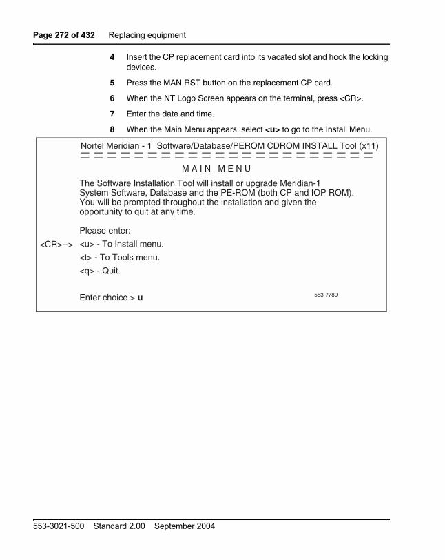
Page 272 of 432 Replacing equipment
553-3021-500 Standard 2.00 September 2004
4 Insert the CP replacement card into its vacated slot and hook the locking devices.
5 Press the MAN RST button on the replacement CP card.
6 When the NT Logo Screen appears on the terminal, press <CR>.
7 Enter the date and time.
8 When the Main Menu appears, select <u> to go to the Install Menu.
Nortel Meridian - 1 Software/Database/PEROM CDROM INSTALL Tool (x11)
M A I N M E N U
The Software Installation Tool will install or upgrade Meridian-1System Software, Database and the PE-ROM (both CP and IOP ROM). You will be prompted throughout the installation and given the opportunity to quit at any time.
Please enter:
<u> - To Install menu.
<t> - To Tools menu.
<q> - Quit.
Enter choice > u
<CR>-->
553-7780
— — — — — — — — — — — — — — — — — — — — — —— — — — — — — — — — — — — — — — — — — — — —

Replacing equipment Page 273 of 432
Communication Server 1000M and Meridian 1 Large System Maintenance
9 Insert the Keycode diskette when prompted and select <a> to continue with the keycode validation.
10 Select the following options in sequence from the Install Menu:
11 When the Install Menu appears, select the following options in sequence
12 A Status Summary is displayed indicating what was installed. Press <CR> to return to the Install Menu.
13 Remove the diskette from the IODU/C.
<g> to reinstall CP software
<y> to start installation
<a> to continue ROM upgrade
<cr> to return to the Install Menu
<e> to install CP-BOOTROM
<y> to start installation
<a> to continue with the upgrade
Nortel Meridian - 1 Software/Database/PEROM CDROM INSTALL Tool (x11)
Please insert the diskette with the keycode file into the floppydrive.
Please enter:
<a> - Continue with the keycode validation
(the keycode diskette is in the floppy drive).
<q> - Quit.
Enter Choice > a
<CR>-->
553-7729
— — — — — — — — — — — — — — — — — — — — — — — — — — — — — — — — — — — — — — — — — — — —

Page 274 of 432 Replacing equipment
553-3021-500 Standard 2.00 September 2004
14 Select the following options to quit the Install Tool:
Note: The system will reboot. Wait for the “INI” and “DONE” messages to display before continuing. It will take at least 70 seconds between the “DONE” and “INI” messages.
After the system initialization has finished (INI messages are no longer displayed on the system terminal), check for dial tone on a telephone set.
Following a successful dial tone test, perform the following basic sanity tests:
a. Make sure calls can be placed.
b. Check for error messages, line noise, chatter, or other problems. Track sources and resolve problems as necessary.
To place the system back in the redundant (normal) mode with automatic switchover capability. Perform the following five steps in uninterrupted sequence on the inactive Core (the Core with the replaced CP card):
15 Press and hold down the MAN RST button on the CP card of the inactive Core.
16 While holding down the MAN RST button, set the NORM/MAINT switch on the same CP card to NORM.
17 Enable all CNI switches in the inactive Core.
18 Release the MAN RST button.
19 Set the CP card in the active Core to NORM.
After several minutes, an “HWI533” message is issued by the active Core indicating that the inactive Core memory is being synchronized with the active Core memory.
20 Log into the system through the terminal, then check the status of the replacement CP card from the active side:
<q> to quit
<y> to confirm quit
<a> to reboot the system.
LD 135 load LD 135
STAT CPU obtain the CPU status

Replacing equipment Page 275 of 432
Communication Server 1000M and Meridian 1 Large System Maintenance
21 If there are CCED messages generated by the STAT CPU command on the replacement CP card, set the NORM/MAINT switch to MAINT, press the reload (MAN RST) button, and set the NORM/MAINT switch back to NORM. (It may take 2 to 4 minutes for memory synchronization to take place.)
After the HWI0533 message is displayed, test the replacement CP card from the active CPU:
22 Set the NORM/MAINT switch to NORM on the active CP card (if not already set).
23 Check the status of the CPUs:
STAT CPU
24 Test the CPU.
TEST CPU
25 Check the status of the CNIs:
STAT CNI
26 Switch Cores and exit the program:
27 The CP card you are replacing must be in the inactive Core. Check the status of the NT5D10 Call Processor cards:
TEST CPU the test causes a cold start on the inactive CPU
If the test results in:
CCED014 “Test failed because unable to enter SPLIT mode”
On the active CP card set the NORM/MAINT switch to NORM, and from the active side enter:
TEST CPU to test the CP card
SCPU**** exit LD 135
LD 135STAT CPU determine which CP card is active
If necessary, switch Cores:
SCPU switch Cores
**** exit LD 135

Page 276 of 432 Replacing equipment
553-3021-500 Standard 2.00 September 2004
28 Set the NORM/MAINT switch on the NT5D10 Call Processor card to MAINT on the active Core.
29 Set the ENB/DIS switch on all CNI cards on the inactive Core to DIS.
30 Perform the following three steps on the inactive Core in an uninterrupted sequence:
a. Press and hold down the MAN RST button on the CP card on the inactive Core.
b. Set the NORM/MAINT switch to MAINT.
c. Release the MAN RST button.
The system is now in split mode where each Core is functioning independently and the automatic switchover has been disabled.
Installing equipment
1 Set the NORM/MAINT switch to MAINT on the replacement card.
2 Insert disk A1 into the IOP/CMDU or CMDU.
3 Remove the current CP card and put it in a static bag and box.
4 Ensure the NORM/MAINT switch is set to MAINT, and insert the CP replacement card into its vacated slot and hook the locking devices.
5 Press the MAN RST button on the replacement CP card.
6 Select the following options in sequence from the Install Menu:
7 At the Install Menu, select the following options in sequence
<g> to reinstall CP software
<y> to start installation
<y> to continue installation
<a> to continue with ROM upgrade
<cr> to return to the Install Menu
<e> to install CP-BOOTROM
<y> to start installation
<y> to continue installation
<a> to continue with ROM upgrade
<cr> to return to the Install Menu

Replacing equipment Page 277 of 432
Communication Server 1000M and Meridian 1 Large System Maintenance
8 Remove the diskette from the IOP/CMDU or CMDU.
9 Select the following options to quit:
Note: The system will reboot. Wait for the “INI” and “DONE” messages to display before continuing. It will take at least 70 seconds between the “DONE” and “INI” messages.
After the system initialization has finished (INI messages are no longer displayed on the system terminal), check for dial tone on a telephone set.
10 Following a successful dial tone test, perform the following basic sanity tests:
a. Make sure calls can be placed.
b. Check for error messages, line noise, chatter, or other problems. Track sources and resolve problems as necessary.
To place the system back in the redundant (normal) mode with automatic switchover capability. Perform the following five steps in uninterrupted sequence on the inactive Core (the Core with the replaced CP card):
11 Press and hold down the MAN RST button on the CP card of the inactive Core.
12 While holding down the MAN RST button, set the NORM/MAINT switch on the same CP card to NORM.
13 Enable all CNI switches in the inactive Core.
14 Release the MAN RST button.
15 Set the CP card in the active Core to NORM.
After several minutes, an “HWI533” message is issued by the active Core indicating that the inactive Core memory is being synchronized with the active Core memory.
16 Log into the system through the terminal, then check the status of the replacement CP card from the active side:
<q> to quit
<y> to confirm quit
<a> to reboot the system.
LD 135 load L 135
STAT CPU obtain the CPU status

Page 278 of 432 Replacing equipment
553-3021-500 Standard 2.00 September 2004
17 If there are CCED messages generated by the STAT CPU command on the replacement CP card, set the NORM/MAINT switch to MAINT, press the reload (MAN RST) button, and set the NORM/MAINT switch back to NORM. (It may take two to four minutes for memory synchronization to take place.)
After the HWI0533 message is displayed, test the replacement CP card from the active CPU:
18 Set the NORM/MAINT switch to NORM on the active CP card (if not already set).
19 Check the status of the CPUs:
STAT CPU
20 Test the CPU.
TEST CPU
21 Check the status of the CNIs:
STAT CNI
iii. Switch Cores and exit the program:
NT5D12AA Dual DTI/PRI (DDP)Use this procedure to replace an NT5D12AA DDP card. See Software Input/Output: Administration (553-3001-311) for a description of all
TEST CPU the test causes a cold start on the inactive CPU
If the test results in:
CCED014 “Test failed because unable to enter SPLIT mode”
On the active CP card set the NORM/MAINT switch to NORM, and from the active side enter:
TEST CPU to test the CP card
SCPU**** exit LD 135
Replacing equipment Page 279 of 432
Communication Server 1000M and Meridian 1 Large System Maintenance
maintenance commands, and Software Input/Output: System Messages (553-3001-411) for interpreting system messages.
Removing the DDP card
1 Determine the cabinet and shelf location of the DDP card to be removed.
2 Disable Network Loop using Overlay 60. The command is DISL “loop number”.
The associated DCHI may have to be disabled first. The faceplate switch S1 should not be disabled until both PRI loops are disabled first.
3 If the DDP card is being completely removed, not replaced, remove data from memory. See ISDN Primary Rate Interface: Features (553-3001-369).
4 Remove cross connections at the MDF to the wall-mounted cross-connect terminal.
5 Tag and disconnect cables from the card.
DANGERModule covers are not hinged; do not let go of the cover. Lift the cover away from the module and set it out of your work area.
CAUTION WITH ESDS DEVICESThe static discharge bracelet located inside the cabinet must be worn before handling circuit cards. Failure to wear the bracelet can result in damage to the circuit cards.

Page 280 of 432 Replacing equipment
553-3021-500 Standard 2.00 September 2004
6 Rearrange Clock Controller cables, if required.
7 In the other circuit of a DDP card is in use, DO NOT remove the card.
8 Remove the DDP card if both loops are disabled. Switch S1 (faceplate switch) must be in the OFF (DIS) position before you remove the card.
9 Package and store the DDP card and cables.
Installing the DDP card
Set the option switches on the DDP circuit card before installation; see Table 2 below, where bold font indicates factory settings.
Note: SW1 (faceplate switch) must be off (DIS) when installing the DDP.SW1 on the DDP corresponds to the faceplate switch on the QPC414 Network card.
CAUTIONSystem FailureDo not route Clock Controller cables connecting the Clock Controller and DDP card through the center of the cabinet past the power harness. Instead, route them around the outside of the equipment shelves.
Table 37DDP general purpose switch settings
Switch Description S9/S15 Switch Setting
1 Framing mode off = ESFon = SF
2 Yellow alarm method off = FDLon = Digit2
3 Zero code suppression mode off = B8ZSon = AMI
4 Unused off

Replacing equipment Page 281 of 432
Communication Server 1000M and Meridian 1 Large System Maintenance
10 Run and connect the DDP cables.
11 Enable faceplate switch S1. This is the “Loop Enable” switch.
The faceplate LEDs should light for four seconds, then go out, and the OOS, DIS, and ACT LEDs should light again and stay lit.
If DDCH is installed, the DCH LED should flash 3 times.
12 Run PRI/DTI Verification Test. Refer to the ISDN Primary Rate Interface: Maintenance (553-3001-517).
13 Run PRI status check. Refer to the ISDN Primary Rate Interface: Maintenance (553-3001-517) for the PRI verification tests, DDP self-test, PRI status check, and PRI start-up test.
NT5D61 Input/Output Disk Unit with CD-ROM (IODU/C)Use this procedure to replace a faulty IODU/C card with a new IODU/C card.
See Software Input/Output: Administration (553-3001-311) for a description of all maintenance commands, and Software Input/Output: System Messages (553-3001-411) for interpreting system messages.
CAUTIONSystem FailureDo not route Clock Controller cables connecting the Clock Controller and DDP card through the center of the cabinet past the power harness. Instead, route them around the outside of the equipment shelves.
DANGERModule covers are not hinged; do not let go of the cover. Lift the cover away from the module and set it out of your work area.

Page 282 of 432 Replacing equipment
553-3021-500 Standard 2.00 September 2004
Performing a data dump
Before starting this procedure, make a backup copy of the customer database on a 4MB diskette using the data dump routine:
1 Log into the system
2 Load the Equipment Data Dump Program (LD 43). At the prompt, enter
3 When “EDD000” appears on the terminal, enter
4 When “DATADUMP COMPLETE” and “DATABASE BACKUP COMPLETE” appear on the terminal, enter
To access the Core during the replacement procedure, connect a terminal to the J25 port on the I/O panel in the inactive Core Module or Core/Network Module. To communicate with the processor, you must use the following settings on the terminal:
9600 baud, 7 data, space parity, 1 stop bit, full duplex, XOFF
If you are using only one terminal or a switch box, switch the connection from Core to Core as needed.
CAUTIONService InterruptionAt some point in this procedure the system will warm start, causing a momentary interruption in call processing.
LD 43 to load the program
EDD to begin the data dump
**** to exit the program
CAUTIONSystem FailureIf the data dump is not successful, do not continue; contact your technical support organization. A data dump problem must be corrected before proceeding.

Replacing equipment Page 283 of 432
Communication Server 1000M and Meridian 1 Large System Maintenance
Splitting the Cores
1 Verify that the disk drives are synchronized:
If the disks are synchronized, proceed with step 2 on page 283. If they are not synchronized, execute the SYNC command:
2 Verify that the clock controller associated with the faulty IODU/C is inactive. If it is not, switch clock controllers:
3 Verify that the IODU/C card you are replacing is on the inactive Core:
If the IODU/C you are replacing is on the inactive Core, proceed with step 5 on page 283. If the IODU/C you are replacing is not on the inactive Core, swap Cores and verify again:
4 Verify that the faulty IODU/C is inactive. You may need to switch IODU/Cs.
5 Set the MAINT/NORM switch on the CP card to MAINT on the active Core.
LD 137 to load the program
STAT to get the status of the disk drives
SYNC to synchronize the drives
**** to exit the program
LD 60 to load the program
SSCK to get the status of the clock controllers
SWCK to switch clock controllers (if necessary)
**** to exit the program
LD 135 to load the program
STAT CPU to check CPU status
TEST CPU to test the CPU
SCPU to swap CPUs
STAT CPU to check CPU status
LD 137STAT Get the status of IODU/C.SWAP Switch IODU/Cs (if necessary).

Page 284 of 432 Replacing equipment
553-3021-500 Standard 2.00 September 2004
6 Set the ENB/DIS switch on all CNI cards to DIS on the inactive Core.
7 Perform the following three steps in uninterrupted sequence:
a. press and hold the MAN RST button on the CP card in the inactive Core
b. set the MAINT/NORM switch on the CP card in the inactive Core to MAINT
c. release the MAN RST button
Replacing the IODU/C in a redundant system
1 Set the ENB/DIS switch on the faulty IODU/C to DIS.
2 Unhook the locking devices and remove the IODU/C.
3 Remove the round 1/2” diameter IODU/C Security Device from the black round Security Device holder on the top right corner of the IODU/C card being replaced.
4 Put the IODU/C being replaced into a static bag and box.
5 With the Nortel side facing upward, slide the Security Device between the security device holder and the holder clip in the new IODU/C card. Do not bend the clip more than necessary when inserting the Security Device. Ensure that the Security Device is securely in place.
6 Insert the new IODU/C into the following slots:
a. For NT5D21 Core/Net Modules, insert the IODU/C in slots 17,18, and 19.
7 Lock the locking devices by pushing them gently towards the faceplate. Set the ENB/DIS switch to ENB.
A blinking letter “E” and number “5” displayed indicates that a failure occurred. In that case, reseat the Security Device in its holder and reinsert the card.
8 Press the MAN RST button on the CP card.
Once the keycode is validated against the Security Device, the Install menu is displayed.

Replacing equipment Page 285 of 432
Communication Server 1000M and Meridian 1 Large System Maintenance
9 At the Install menu, select <o> to copy the software from the active Core.
Nortel Meridian - 1 Software/Database/PEROM CDROM INSTALL Tool (x11)
I N S T A L L M E N U
The Software Installation Tool will install or upgrade Meridian-1System Software, Database and the PE-ROM (both CP and IOP ROM). You will be prompted throughout the installation and given the opportunity to quit at any time.
Please enter:
<a> - To install Software, CP-BOOTROM, IOP-ROM.
<b> - To install Software, Database, CP-BOOTROM, IOP-ROM.
<c> - To install Software only.
<d> - To install Database only.
<e> - To install CP-BOOTROM only.
<f> - To install IOP-ROM only.
<g> - To reinstall CP-Software.
<o> - To copy System Software from the other Core.
<t> - To go to the Tools menu.
<k> - To install Keycode only.
For Feature Expansion, use OVL143.
<q> - Quit.
Enter choice > o
<CR>-->
553-7784
— — — — — — — — — — — — — — — — — — — — — — —— — — — — — — — — — — — — — — — — — — — — — —
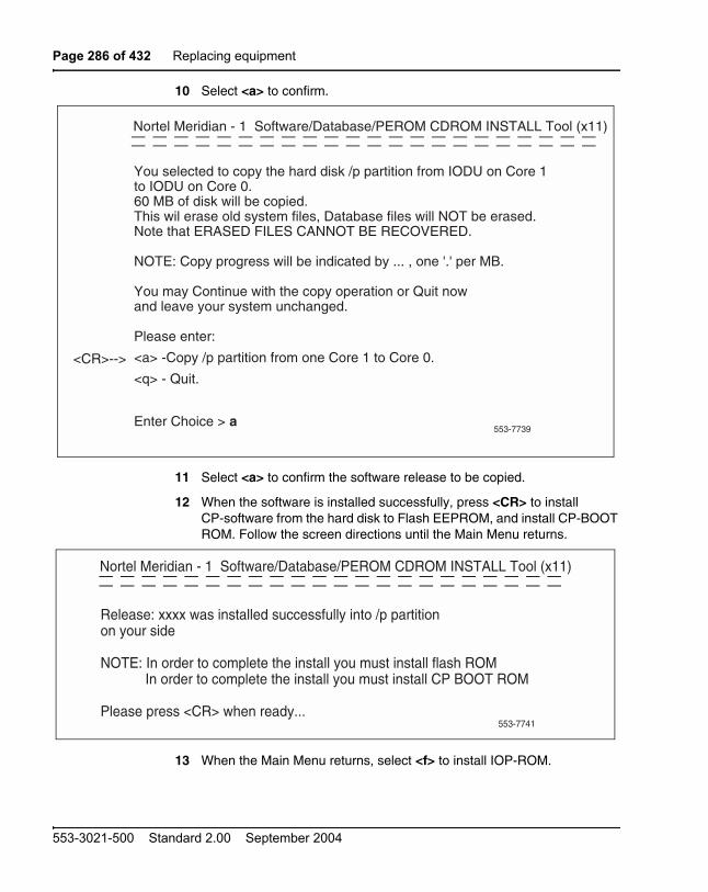
Page 286 of 432 Replacing equipment
553-3021-500 Standard 2.00 September 2004
10 Select <a> to confirm.
11 Select <a> to confirm the software release to be copied.
12 When the software is installed successfully, press <CR> to install CP-software from the hard disk to Flash EEPROM, and install CP-BOOT ROM. Follow the screen directions until the Main Menu returns.
13 When the Main Menu returns, select <f> to install IOP-ROM.
Nortel Meridian - 1 Software/Database/PEROM CDROM INSTALL Tool (x11)
You selected to copy the hard disk /p partition from IODU on Core 1to IODU on Core 0.60 MB of disk will be copied.This wil erase old system files, Database files will NOT be erased.Note that ERASED FILES CANNOT BE RECOVERED.
NOTE: Copy progress will be indicated by ... , one '.' per MB.
You may Continue with the copy operation or Quit nowand leave your system unchanged.
Please enter:
<a> -Copy /p partition from one Core 1 to Core 0.
<q> - Quit.
Enter Choice > a
<CR>-->
553-7739
— — — — — — — — — — — — — — — — — — — — — — — — — — — — — — — — — — — — — — — — — — — —
Nortel Meridian - 1 Software/Database/PEROM CDROM INSTALL Tool (x11)
Release: xxxx was installed successfully into /p partitionon your side
NOTE: In order to complete the install you must install flash ROMIn order to complete the install you must install CP BOOT ROM
Please press <CR> when ready...
553-7741
— — — — — — — — — — — — — — — — — — — — — — — — — — — — — — — — — — — — — — — — — — — —

Replacing equipment Page 287 of 432
Communication Server 1000M and Meridian 1 Large System Maintenance
14 Select <a> to continue with the IOP-ROM upgrade.
15 At the Install Menu, select the following options in sequence to copy the customer database from the redundant disk.
16 Remove the diskette from the IODU/C and select <q> to quit and reload the system.
17 Select <y> to confirm quit
18 Select <a> to reboot the system.
The system will automatically perform a sysload and system initialization during which several messages will appear on the system terminal. Wait until initialization has finished (INI messages are no longer displayed on the system terminal) before continuing.
19 In the inactive Core, enable the NT6D65 CNI cards by setting the ENB/DIS faceplate switches to ENB.
<d> to go to the Database menu
<d> to copy the database from the redundant disk
<y> to confirm installation status summary
<a> to confirm database copy
Nortel Meridian - 1 Software/Database/PEROM CDROM INSTALL Tool (x11)— — — — — — — — — — — — — — — — — — — —— — — — — — — — — — — — — — — — — — — —
You have chosen to Upgrade IOP-ROM in card slot xx fromthe context: x11xxxx to the context: x11xxxx.
This will replace old IOP-ROM with the ROM image files:"/p/os/ioprom".
You may Continue with ROM upgrade or Quit now and leave ROMunchanged.
Please enter:
<a> - Continue with ROM Upgrade.
<q> - Quit.
Enter choice > a
<CR>-->
553-7787

Page 288 of 432 Replacing equipment
553-3021-500 Standard 2.00 September 2004
20 In the inactive Core, perform the following steps in uninterrupted sequence:
a. press and release the MAN RST button
b. when SYS700 messages appear on CP LCD display, set the MAINT/NORM switch to NORM.
Within 60 seconds, the LCD will display the following messages, confirming the process.
RUNNING ROM OSENTERING CP VOTE
An “HWI534” message from the CPSI or SDI port indicates the start of memory synchronization. Within 10 minutes, an HWI533 message on the inactive Core CPSI or SDI TTY indicates the memory synchronization is taking place. Wait until the memory synchronization is complete.
21 Switch the NORM/MAINT switch on the active CP card to NORM.
22 Synchronize the disk drives:
Note: Synchronization may take up to 50 minutes.
NT5D61 IODU/C Security Device Use this procedure to replace the Security Device on the NT5D61 Input/Output Disk Unit with CD-ROM (IODU/C) Card.
The Security Device is a field removable component and is located in the upper right corner of an IODU/C card. The device does not contain feature or software release specific information, but it has a unique custom program necessary for each customer. It is intended to serve the customer through numerous upgrade and feature changes.
The Security Device is replaced only if such a replacement is suggested by maintenance and/or diagnostic programs.
LD 137 to load the program
SYNC to synchronize the drives
**** to exit the program
Replacing equipment Page 289 of 432
Communication Server 1000M and Meridian 1 Large System Maintenance
See Software Input/Output: Administration (553-3001-311) for a description of all maintenance commands, and Software Input/Output: System Messages (553-3001-411) for interpreting system messages.
Note: To replace the Security Device, a new Security Device and keycode are required. On redundant systems, the new keycode must validate against the new and existing Security Device.
Replacing the Security Device on a redundant system
The procedure begins with the validation of the new Keycode against the existing Security Device.
1 To access the Core during the replacement procedure, connect a terminal to the J25 port on the I/O panel in the inactive Core Module or Core/Network Module. To communicate with the processor, you must use the following settings on the terminal:
9600 baud, 7 data, space parity, 1 stop bit, full duplex, XOFF
Note: If you are using only one terminal or a switch box, switch the connection from Core to Core as needed.
DANGERModule covers are not hinged; do not let go of the cover. Lift the cover away from the module and set it out of your work area.
CAUTIONService InterruptionAt some point in this procedure the system will warm start, causing a momentary interruption in call processing.

Page 290 of 432 Replacing equipment
553-3021-500 Standard 2.00 September 2004
2 Use LD 135 to switch to the Core which contains the non-faulty Security Device.
3 Insert the keycode diskette into the floppy drive on the IODU/C with the non-faulty Security Device.
4 In LD 143, print the pending keycode contents. Use “KSHO F0” if your keycode is on the diskette in the floppy drive on Core 0, or “KSHO F1” if your keycode is on the diskette in the floppy drive on Core 1:
5 Perform the KDIF command. Use “KDIF F0 REC” if the keycode diskette is inserted in the floppy drive on Core 0, or “KDIF F1 REC” if the keycode is inserted in the floppy drive on Core 1:
6 Disable the inactive IODU/C:
Perform the following steps on the inactive Core.
7 Set the ENB/DIS switch on the IODU/C with the faulty Security Device to DIS.
8 Unhook the locking devices and remove the IODU/C.
9 Remove the round 1/2” diameter IODU/C Security Device from the black round Security Device holder on the top right corner of the IODU/C card.
10 Locate the round 1/2” diameter IODU/C replacement Security Device.
LD 135 to load the program
SCPU switch CPUs (if necessary)
**** exit LD 135
LD 143 to load the program
KSHO F0or KSHO F1
print the contents of the candidate keycode
KDIF F0 RECor KDIF F1 REC
to print the differences between the candidate and the current keycodes
**** to exit LD 143
LD 137 to load the program
STAT to find the status of the IODU/Cs
DIS CMDU x to disable the CMDU part of the inactive IODU/C x
DIS IOP x to disable the IOP part of the inactive IODU/C x

Replacing equipment Page 291 of 432
Communication Server 1000M and Meridian 1 Large System Maintenance
11 Make sure the 8-digit code on the Keycode diskette matches the 8-digit code on the replacement Security Device.
12 With the Nortel side facing upward, slide the replacement Security Device between the security device holder and the holder clip. Do not bend the clip more than necessary when inserting the Security Device. Ensure that the Security Device is securely in place.
13 Reinsert the IODU/C into the following slots:
— For NT5D21 Core/Net Modules, insert the IODU/C in slots 17,18, and 19.
14 Lock the locking devices by pushing them gently towards the faceplate. Set the ENB/DIS switch to ENB.
A blinking letter “E” and number “5” displayed indicates that a failure occurred. In that case, reseat the Security Device in its holder and reinsert the card.
15 Enable the IODU/C in LD 137:
16 Perform the KNEW command:
17 Reboot the system at a time that will minimize service impact.
The new keycode will not take effect until the system reboots.
NT5D2103 Core/Network Card CageTo replace a defective backplane in an NT5D21 Core/Network Module, you must replace the card cage.
Use this procedure to replace the card cage in a redundant system by maintaining system operation with the active CPU and replacing the card cage of the standby CPU. See Software Input/Output: Administration
STAT to see the status of the IODU/Cs
ENL CMDU x to enable the CMDU part of IODU/C x
ENL IOP x to enable the IOP part of IODU/C x
STAT to see the status of the IODU/Cs
**** to exit LD 137
LD 143 to load the program
KNEW HD to copy the keycode to the other Core
**** to exit the program

Page 292 of 432 Replacing equipment
553-3021-500 Standard 2.00 September 2004
(553-3001-311) for a description of all maintenance commands, and Software Input/Output: System Messages (553-3001-411) for interpreting system messages.
Removing equipment
1 To access the Cores during the replacement procedure, connect a terminal to the J25 port on the I/O panel in the rear of each Core/Network Module. You must use the following settings on the terminal:
9600 baud, 7 data, space parity, 1 stop bit, full duplex, XON
Note: If you are using only one terminal or a switch box, switch the connection from Core to Core as needed.
2 The Call Processor (CP) Card must be inactive in the card cage you are replacing.
a. Check the status of the CP cards:
b. Set the NORM/MAINT switch to MAINT on the now active CP card.
c. Connect the terminal to the port on the inactive Core.
3 Set the NORM/MAINT switch to MAINT on the CP card in the card cage you are replacing (the inactive Core). Wait 2 minutes for the system to initialize. (A series of INI messages will be seen on the terminal for the inactive Core.)
4 Disable the clock controller card and any QPC720 Primary Rate Interface or QPC472 Digital Trunk Interface (PRI/DTI) Cards in the card cage you are replacing.
DANGERModule covers are not hinged; do not let go of the cover. Lift the cover away from the module and set it out of your work area.
LD 135STAT CPU determine which CP card is active
If necessary, switch Cores:
SCPU switch Cores
**** exit LD 135

Replacing equipment Page 293 of 432
Communication Server 1000M and Meridian 1 Large System Maintenance
a. Check the status of the clock controller cards:
b. Set the ENB/DIS switch to DIS on the clock controller card in the card cage you are replacing.
c. Disable any PRI/DTI cards in the card cage you are replacing.
Note: If the PRI/DTI cards service loops that cannot be out of service, move the cards to a different module and reenable them.
5 Set the ENB/DIS switch to DIS on all CNI cards and the IODV/C in the card cage you are replacing.
6 Follow the steps below to disconnect and remove the NT8D22 System Monitor (do not turn off the blower unit in the front of the pedestals):
a. Load LD 37 and software disable the associated SDI port:
b. If the card cage you are removing is in the column with the master system monitor (should be column 0):
On the master system monitor (column 0), disconnect the RJ11 cable to J3, then the cable to J6, then pull the system monitor out of the slot.
c. If the card cage you are removing is in the column with a slave system monitor (should be column 1):
On the master system monitor (column 0), disconnect the RJ11 cable to J3, then the cable to J6, then pull the system monitor out of the slot.
LD 60SSCK x “x” is the Core (0 or 1)
If the clock controller card is active, switch to make it inactive:
SWCKDisable the clock controller card:
DIS CC x “x” is the Core (0 or 1)
DISL loop disable the network loop and the card
**** exit LD 60
LD 37DIS TTY x disable the device associated with the port
**** exit LD 37

Page 294 of 432 Replacing equipment
553-3021-500 Standard 2.00 September 2004
On column 1, disconnect the cables, then pull the system monitor out of the slot.
7 Follow the appropriate step below to turn off power to the module:
a. With AC power, set the main circuit breaker for the column to OFF (down) in the rear of the pedestal.
b. With DC power, set the switch on the NT6D41 CE Power Supply to OFF (down). Set the circuit breaker for just this module to OFF (down) in the rear of the pedestal. (All other modules in the column retain power.)
8 Follow the steps below to remove all cards from the module:
a. Tag and disconnect all cables to the front of the module. Tape over the contacts to avoid grounding. Tape or tie all cables to the sides so the working area in front of the card cage is totally clear.
b. Set the ENB/DIS switch to DIS on any cards that are not already set to disable.
c. Tag the cards so they can be returned to the same slot in the replacement card cage. Remove the cards, including the bus terminating units (BTUs) between slots 4 and 5.
9 Follow the steps below to disconnect cables to the I/O panels and backplane at the rear of the module:
CAUTIONService InterruptionIf the system monitors are not removed, the system may shut down.
DANGER OF ELECTRIC SHOCKDue to hazardous voltage in ac-powered systems, power to the entire column must be shut down. This shuts down all functions in the column including the network group in that column. Relocate essential services from this group before proceeding.

Replacing equipment Page 295 of 432
Communication Server 1000M and Meridian 1 Large System Maintenance
a. Tag and disconnect cables from the I/O panels.
b. Remove the I/O panels and the I/O safety panel over the backplane to access the rear backplane connectors.
c. Use the P0741489 Extraction Tool to disconnect cables to the backplane connectors. (See “System cable guidelines” on page 213.)
10 Follow the steps below to disengage the module:
a. Remove the two mounting screws that secure the rear of the card cage to the module.
b. Remove the front trim panels on each side of the card cage.
c. Remove the three mounting screws that secure the front of the card cage to the bottom of the module.
d. Pull the card cage halfway out of the module.
11 Follow the steps below to disconnect power and ground connections at the rear of the module:
a. Disconnect the system monitor ribbon cables to J1 and J2.
b. Disconnect the module power connectors. These are small orange connectors plugged into the module power distribution unit (MPDU) with AC power, or connected to each other with DC power.
c. Disconnect the logic ground (orange) wire from the backplane bolt.
d. Disconnect the frame ground (green) wire from the frame ground post.
12 Pull the card cage all the way out of the module.
Note: For AC-powered systems, after the card cage is out of the module you must remove the MPDU and reinstall it on the replacement card cage. The screw-heads for the MPDU are in the wall of the power supply slot.
CAUTIONService InterruptionDo not disconnect the main power connectors (large orange connectors) at the top and bottom of the module.

Page 296 of 432 Replacing equipment
553-3021-500 Standard 2.00 September 2004
13 Remove the floating power connector (the black connector) on the rear of the card cage. Using the same mounting screws and nuts, attach the connector to the new card cage.
Note: Check the orientation of the connector. Looking at it from the rear of the card cage, the upper left corner pin should be empty (no wire) and the lower right corner pin should have a wire installed. The green wire should be up.
Installing equipment
14 Set the backplane jumpers in the card cage for Core/Network 0 and Core/Network 1. The jumpers are located on the backplane, along the bottom of the front side (the side facing into the card cage assembly):
a. For Core/Network 0, verify that the jumper between card slots 14 and 15 is closed.
b. For Core/Network 1, verify that the jumper between card slots 14 and 15 is open.
15 Reposition the EMI shield (it looks like a brass grill) in the base of the module. Tape over the front mounting tabs to hold the shield in position. The tape will be removed later.
16 Slide the new card cage about halfway into the module. Hold the card cage firmly while the ground and power connections are attached at the rear of the module:
a. Attach the system monitor ribbon cables (J1 goes down to the pedestal, J2 goes up the column).
b. Attach the frame ground (green) wire to the frame ground post on the module. (A 5/16” socket wrench is needed for this operation.) Remove the nut and the lockwasher at the top of the post. Put the frame ground connector over the post. Reinstall the top lockwasher and the nut, then tighten the nut down.
CAUTIONSystem FailureIf the Core/Network Module jumpers are set incorrectly, the system will not load and operate correctly.

Replacing equipment Page 297 of 432
Communication Server 1000M and Meridian 1 Large System Maintenance
c. Attach the logic ground (orange) wire. Remove one nut and the lockwasher. Put the connector over the post, reinstall the lockwasher and nut, then tighten the nut down. (A 3/8” socket wrench is needed for this operation.)
d. Connect the module power connectors to the MPDU for AC power, or to each other for DC power.
17 Follow the steps below to install the new card cage in the module:
a. Slide the card cage the remainder of the way into the module.
b. Check the position of the EMI shield. If it has shifted, reposition it. Remove the tape holding the EMI shield.
c. Secure the card cage to the module with the three screws in the front and the two screws in the rear.
18 Replace the trim panels on both sides of the card cage.
19 Install the module power supply in the slot labeled “CE pwr sup” in the Core/Network card cage. Perform a hardware sanity check:
a. Turn on power to the module:
With AC power, set the main circuit breaker to ON (up) in the rear of the pedestal.
With DC power, set the breaker to ON (up) in the pedestal, then set the switch to ON (up) on the power supply in the module.
b. Check the LED pattern for the card cage you are installing:
— On the NT5D2103 card cage, the LEDs are on the front side of the backplane. The LEDs are in two vertical columns, one on either side of slot 12 (if necessary, remove the CNI card to view the LEDs). The LEDs on the right side of the slot apply to Core 0 and must be (from the top down) OFF-OFF-OFF-OFF. Those on the left side apply to Core 1 and must be ON-OFF-OFF- OFF.
c. Shut down power to the module again.
With AC power, set the main breaker for the column to OFF (down).
With DC power, set the switch on the power supply and the pedestal breaker for the module to OFF (down).

Page 298 of 432 Replacing equipment
553-3021-500 Standard 2.00 September 2004
20 Install the module power supply in the slot labeled “CE pwr sup” in the Core/Network card cage.Follow the steps below to reconnect cables to the backplane:
a. Reconnect all cables to the backplane connectors.
b. Route the NTND14 CNI to 3PE cables to the right side (facing the rear) of the module and tie-wrap them to the cable restraint bracket behind the I/O panel.
c. Position and secure the I/O panels.
d. Position and secure the I/O safety panel.
21 Reinstall the 3PE card. Set the ENB/DIS switch to ENB.
22 Set the ENB/DIS switch on the clock controller card to DIS. Seat the clock controller card; leave the ENB/DIS switch set to DIS and do not connect the faceplate cables.
23 Follow the appropriate step below to turn on power to the column or the module power supply:
a. With AC power, set the main circuit breaker in the pedestal to ON (up).
b. With DC power, set the breaker to ON (up) in the pedestal. Set the switch to ON (up) on the power supply in the module.
24 Follow the appropriate steps below to connect the clock controller cables:
a. For a QPC471 Clock Controller card, connect the NT8D79 cables from the primary or secondary reference to the faceplate of the clock
CAUTIONDamage to EquipmentIf you try to insert the cable connector at an angle, pins may be bent or broken.
Replacing equipment Page 299 of 432
Communication Server 1000M and Meridian 1 Large System Maintenance
controller card. For Meridian 1 PBX 81C, connect the NT8D74 cable from the NT8D36 InterGroup Module to the clock controller card.
b. For QPC775 Clock Controller Cards in Meridian 1 PBX 81C, connect the NT8D74 cable from the junctor board to the faceplate of the clock controller card. Then connect the NT8D79 cables from the primary or secondary reference to the faceplate of the clock controller card.
c. Leave the ENB/DIS switch set to DIS on QPC471 or QPC775 cards.
25 Set the NORM/MAINT switch on the CP card to MAINT. (This will keep the system in split mode when the card is reinstalled.)
26 Reinstall the CP card. As the card performs card-level power-up tests, watch the LCD display and output from the CPSI port for error messages:
a. Following the “Selftest Complete” message, watch the LCD on the CP card for the message “IOP in Slot 16.”
b. Watch the LCD for the message “Loading Disk OS.” As the system attempts to access the hard disk, watch the LCD for error messages.
c. Watch for system reload (SYS) and initialization (INI) messages on the terminal.
27 Seat all CNI cards, but leave the ENB/DIS switches set to DIS.
28 Load LD 135 and check the status of all configured CNI cards:
29 Set the ENB/DIS switch to ENB on the clock controller card.
30 Set the ENB/DIS switch to ENB on all CNI cards.
31 Press and release the MAN RST button on the CP card in the new card cage. When SYS700 messages appear on the LCD display, set the NORM/MAINT switch to NORM. Within 60 seconds, the LCD will display the following messages, confirming the process:
RUNNING ROM OSENTERING CPU VOTE
LD 135STAT CNI get the status of all configured CNIs
TEST CNI c s test each configured CNI on the inactive side
**** exit LD 135

Page 300 of 432 Replacing equipment
553-3021-500 Standard 2.00 September 2004
By the active CPU, an HWI533 message from the CPSI or SDI port indicates the memory is shadowed.
Note 1: At this point, the other Core is still active and in split mode. The Core in the new card cage is the standby (inactive) side. The memories are shadowed (synchronized), but the hard disks are not synchronized (redundancy is disabled).
Note 2: A CNI port LED may not go out if a network loop corresponding to that port is disabled.
32 Set the NORM/MAINT switch to NORM on the CP card in the active Core and perform a redundancy sanity test:
Note: Testing the CP and CNI cards can take 2 minutes or more for each test.
33 Switch Cores and test the other side:
34 Get the status of the CP cards and memories, and of the CNIs:
35 Synchronize the disk drives:
Note: Synchronization may take up to 50 minutes.
36 Test Core functions:
LD 135STAT CNI get the status of all configured CNIs
STAT CPU get the status of both Cores
TEST CPU test the inactive CP card and CP to CP cable
TEST CNI c s test each configured CNI on the inactive side
SCPU switch to Core 0
TEST CPU test the inactive CP card and CP to CP cable
STAT CPU get the status of both Cores
STAT CNI get the status of all configured CNIs
**** exit LD 135
LD 137SYNC synchronize the hard disks
LD 135TEST CPU test the inactive CP card and CP to CP cable

Replacing equipment Page 301 of 432
Communication Server 1000M and Meridian 1 Large System Maintenance
37 Clear displays, major alarms, and minor alarms:
38 Software enable, from the active side, the clock controller and PRI/DTI cards:
a. Enable the clock controller card:
b. Enable the PRI/DTI cards:
39 Follow the appropriate steps below to reinstall and check the system monitor:
a. If you replaced the card cage in the column with the master system monitor:
Reconnect the RJ11 cable to J6, then the cable to J3. Reinstall the system monitor.
TEST IPB test the backplane protocol on the inactive side
TEST CNI c s test each configured CNI on the inactive side
If all the tests pass, switch Cores and test the side that is now inactive:
SCPU switch to the other Core
TEST CPU test the inactive CP card and CP to CP cable
TEST IPB test the backplane protocol on the inactive side
TEST CNI c s test each configured CNI on the inactive side
CDSP clear the display
CMAJ clear all major alarms
CMIN ALL clear all minor alarms
SCPU switch to the other Core
CDSP clear the display
**** exit LD 135
LD 60ENL CC xTRCK aaa if necessary, set tracking
ENLL loop**** exit LD 60

Page 302 of 432 Replacing equipment
553-3021-500 Standard 2.00 September 2004
b. If you replaced the card cage in the column with the slave system monitor:
Reinstall the system monitor in column 1 first.
On the master system monitor, reconnect the RJ11 cable to J6, then the cable to J3. Reinstall the system monitor.
c. Enter:
40 Tag defective equipment with a description of the problem and package it for return to a repair center.
NT5K09 Quad Digitone Receiver Use the following procedure to replace a defective Quad DIGITONE Receiver Card.
See Software Input/Output: Administration (553-3001-311) for a description of all maintenance commands, and Software Input/Output: System Messages (553-3001-411) for interpreting system messages.
LD 37STAT XSM check the status of the system monitors
**** exit LD 37
DANGERModule covers are not hinged; do not let go of the cover. Lift the cover away from the module and set it out of your work area.
CAUTIONService InterruptionService is interrupted when a loop is disabled.

Replacing equipment Page 303 of 432
Communication Server 1000M and Meridian 1 Large System Maintenance
Removing equipment
1 Software disable the Quad DTMF Receiver by entering LD 32 DISS l s (“l s” represents loop and shelf number)
2 Remove the backplane access plate at the rear of the UEM by removing the screws on each side. Set the plate aside.
3 Unhook the locking devices on the card; pull it out of the card cage.
Installing equipment
1 Check that the plug P2 0n the replacement card is oriented in the same way as the card being replaced.
2 Insert the replacement card into the vacated slot and hook the locking devices.
3 Position the backplane access plate. Replace the screws.
4 Software enable each loop on the card by entering ENLS l s
5 End the session in LD 32 by entering ****
6 Test each loop on the card by entering LD 30 LOOP l
If there is a problem, an NWS system message will be produced and the appropriate red LED will light on the faceplate of the card.
7 End the session in LD 30 by entering ****
8 Tag defective equipment with a description of the problem and package it for return to a repair center.
NT5K10 Dual Loop Peripheral Buffer Card Use this procedure to replace a defective Enhanced Dual Loop Peripheral Buffer (IDLB) card.

Page 304 of 432 Replacing equipment
553-3021-500 Standard 2.00 September 2004
See Software Input/Output: Administration (553-3001-311) for a description of all maintenance commands, and Software Input/Output: System Messages (553-3001-411) for interpreting system messages.
Removing equipment
1 Software disable the Dual Loop Peripheral Buffer by entering LD 32DISS l s (“l s” represents loop and shelf number)
2 Remove the Backplane access plate at the rear of the UEM by removing the screws on each side. Set the plate aside.
3 Tag and disconnect cables to the card you are removing.
4 Unhook the locking devices on the card; pull it out of the card cage.
Installing equipment
1 Set option switches on the replacement card the same as on the card you removed.
To check switch settings, see Circuit card installation and testing (553-Circuit Card: Description and Installation (553-3001-211)) in the SL-1 installation and maintenance guide.
2 Insert the replacement card into the vacated slot and hook the locking devices.
3 Connect cables to the replacement card.
DANGERModule covers are not hinged; do not let go of the cover. Lift the cover away from the module and set it out of your work area.
CAUTIONService InterruptionService is interrupted when a loop is disabled.

Replacing equipment Page 305 of 432
Communication Server 1000M and Meridian 1 Large System Maintenance
4 Position the backplane access plate. Replace the screws.
5 Software enable each loop on the card by enteringENLS l s
6 End the session in LD 32 by entering ****
7 Test each loop on the card by entering LD 30 LOOP l
If there is a problem, an NWS system message will be produced and the appropriate red LED will light on the faceplate of the card.
8 End the session in LD 30 by entering ****
9 Tag defective equipment with a description of the problem and package it for return to a repair center.
NT5K1106 Enhanced Peripheral Equipment Card Cage To replace a defective NT5K1102 Enhanced Peripheral Equipment Backplane in the NT5K11 EEPE UEM, you must replace the NT5K1106 Enhanced Peripheral Equipment Card Cage Assembly. Use this procedure to replace the unit.
See Software Input/Output: Administration (553-3001-311) for a description of all maintenance commands, and Software Input/Output: System Messages (553-3001-411) for interpreting system messages.
DANGERModule covers are not hinged; do not let go of the cover. Lift the cover away from the module and set it out of your work area.

Page 306 of 432 Replacing equipment
553-3021-500 Standard 2.00 September 2004
Removing equipment
1 Disable the EEPE Enhanced Peripheral Equipment shelf by entering LD 32 DISS l s (“l s c” represents loop, shelf number)
If a second shelf is assigned to a loop, disable that shelf also by entering DISSI 1 s
— If the shelf is in single loop mode, two loops are disabled.
— If the shelf is in dual loop mode, four loops are disabled.
2 Turn off power to the UEM power supply by setting the switch on the NT5K12 Enhanced Equipment power supply to OFF(left).
3 Remove all cards from the shelf of the UEM:
a. Tag and disconnect cables to all faceplate connectors.
b. Tag cards so they can be returned to the same slot. Remove cards.
4 Disconnect cables, plugs, and wires from the back of the UEM to the backplane:
a. Remove the Backplane access plate by removing the screws on each side (see Figure 27). Set the panel aside.
b. Remove all cards from the back of the UEM.
c. Tag and disconnect cables to all faceplate connectors.
d. Tag cards so they can be returned to the same slot. Remove cards.
e. Tag and disconnect all cables from the backplane to the interior of the I/O assembly.
f. Tag and disconnect all plugs, wires, and cables to the backplane.
5 Remove the two mounting screws that secure the back of the card cage to the UEM assembly.
6 Remove the front cover plates on both sides of the card cage.
7 Remove the three mounting screws that secure the front of the card cage to the bottom of the UEM assembly. Pull the card cage out of the UEM.
8 Slide the replacement card cage into position in the UEM leaving approximately 3” clearance between the card cage and the backplane.

Replacing equipment Page 307 of 432
Communication Server 1000M and Meridian 1 Large System Maintenance
9 Reconnect cables, plugs, and wires from the UEM to the backplane:
a. Connect all cables from the interior of the I/O assembly to the backplane.
b. Position the backplane access plate. Replace the screws.
c. Connect all plugs, wires, and cables to the backplane.
Installing equipment
10 Slide the replacement card cage into position in the UEM taking care not to pinch the cables.
11 Install the three mounting screws that secure the front of the card cage to the bottom of the UEM assembly.
12 Replace the front cover plates on both sides of the card cage.
13 Install the mounting screws at the back of the card cage.
14 Reconnect cables, plugs, and wires from the UEM to the backplane:
a. Connect all cables from the interior of the I/O assembly to the backplane.
b. Connect all plugs, wires, and cables to the backplane.
c. Position the power plug access plate. Replace the screws.
15 Return cards to their slots at the rear of the UEM. Reconnect all cables to connectors.
16 Position the backplane access plate. Replace the screws.
17 Return cards to their slots at the front of the UEM. Reconnect all cables to connectors.
Figure 27EEPE access plates (rear view)
power plugaccess plate
backplaneaccess plate
553-7377

Page 308 of 432 Replacing equipment
553-3021-500 Standard 2.00 September 2004
18 Turn on power to the UEM power supply by setting the power supply switch to ON (right):
19 Enable the shelf by enteringENLS l s
If a second shelf is assigned to a loop, enable that shelf also by enteringENLS l s
End the session in LD 32 by entering ****
20 Test the shelf by testing each loop with LD 30 LOOP l s
If there is a problem, an NWS system message will be produced.
21 End the session in LD 30 by entering ****
22 Tag defective equipment with a description of the problem and package it for return to a repair center.
NT5K21AA Extended Multi - Frequency Compelled Sender/Receiver Card
Use this procedure to replace a NT5K21AA card in an IPE Modules.
Removing equipment
1 Software disable the card: LD 32 STAT l s cDIS l s c(“l s c” represents loop, shelf, and card number)
You will see “NPR011” on the system terminal when the card is disabled. Busy channels will not be disabled until the call is disconnected.
DANGERModule covers are not hinged; do not let go of the cover. Lift the cover away from the module and set it out of your work area.

Replacing equipment Page 309 of 432
Communication Server 1000M and Meridian 1 Large System Maintenance
You will see the LED light up when the card becomes disabled.
2 Unhook the locking devices on the card; pull it out of the card cage.
Installing equipment
1 Insert the replacement card into the vacated slot and hook the locking devices.
Note: When IPE cards are installed, the red LED on the faceplate remains lit for 2 to 5 seconds as a self-test runs. If the self-test completes successfully, the LED flashes three times and remains lit until the card is configured and enabled in software, then the LED turns off. If the LED does not follow the pattern described or operates in any other manner (such as continually flashing or remaining weakly lit), replace the card.
2 Software enable the card:LD 32 ENLC l s cWhen the process is complete, you will receive a system responseSTAT l s cObtain the status of the card to ensure that the card is enabled****To exit the program
3 (Optional): Test the card:LD 30 SHLF l s(“l s” represents loop, shelf number)
Note: This command tests every card on the designated shelf.
If there is a problem, an NWS system message is generated and the red LED(s) on the faceplate of the card will remain lit.
If there is no problem, exit LD 30.
4 Tag defective equipment with a description of the problem and package it for return to a repair center.
NT6D40, NT6D41, NT6D42, Power Supply DC Use this procedure to replace the following DC power supplies:
• NT6D40 PE Supply DC
• NT6D41 CE Power Supply DC

Page 310 of 432 Replacing equipment
553-3021-500 Standard 2.00 September 2004
NT6D42 Ringing Generator DC
Removing equipment
1 Set the switch on the front of the power supply to OFF (down).
2 Unhook the locking devices on the power supply; pull it out of the card cage.
Installing equipment
1 Set the switch on the replacement power supply to OFF (down).
Note: On a replacement NT6D42, set option switches the same as on the one you removed. If there is a vintage change, be sure to check Circuit Card: Description and Installation (553-3001-211) for any differences.
2 Insert the replacement power supply into the vacated slot and hook the locking devices.
3 Set the switch on the replacement power supply to ON (up). The green LED on the power supply should light and stay lit.
4 Tag defective equipment with a description of the problem and package it for return to a repair center.
NT6D65 and NTRB34 Core to Network Interface CardsUse this procedure to replace the Core to Network Interface (CNI) or Core to Network Interface 3 (CNI-3) card. See Software Input/Output: Administration (553-3001-311) for a description of all maintenance commands, and Software Input/Output: System Messages (553-3001-411) for interpreting system messages.
DANGERModule covers are not hinged; do not let go of the cover. Lift the cover away from the module and set it out of your work area.

Replacing equipment Page 311 of 432
Communication Server 1000M and Meridian 1 Large System Maintenance
Before replacing a CNI or CNI-3 card, you can test it in an unused CNI slot (in case, for example, there is a bent pin on the backplane). If the card works correctly in the new slot, you can leave it there. To switch slots:
1 The Core associated with the CNI card must be inactive:
— If you need to switch Cores:
LD 135SCPU
a. Set the NORM/MAINT switch to MAINT on the active CP card.
2 Software disable the CNI card:
3 Software configure the new slot:
4 Insert the CNI card in the new slot. Move the cables to the shrouds on the backplane to the connectors for the new slot.
5 Enable the CNI card and switch the CP cards:
DANGERModule covers are not hinged; do not let go of the cover. Lift the cover away from the module and set it out of your work area.
DIS CNI c s “c” is the CPU (0 or 1), “s” is the card slot (8–12)
**** exit LD 135
LD 17EXT x 3PE “x” is the number (0–4) of the associated 3PE
card(s)
CNI X s p delete the group(s) associated slot
CNI s p g add group(s) to new slot
**** exit LD 17
LD 43EDD datadump the new configuration
**** exit LD 43

Page 312 of 432 Replacing equipment
553-3021-500 Standard 2.00 September 2004
a. Set the NORM/MAINT switch to NORM on the active CP card.
b. LD 135ENL CNI c sSCPU****
Use the following procedure to replace a CNI card.
Removing equipment
1 The Core associated with the CNI card must be inactive:
a. If you need to switch Cores:
LD 135SCPU
b. Set the NORM/MAINT switch to MAINT on the active CP card.
2 Set the ENB/DIS switch to DIS on the CNI card you are replacing.
3 Unhook the locking devices on the card; pull it out of the card cage.
Installing equipment
1 Set the ENB/DIS switch to DIS on the replacement card.
2 Insert the replacement card into the vacated slot and hook the locking devices.
3 Set the ENB/DIS switch to ENB on the replacement card.
4 Set the NORM/MAINT switch to NORM on the active CP card.
5 Software enable and test the CNI card and configured ports on the card:
Note: Due to the need to reestablish memory shadowing and contents, the test command may take a minute or more depending on memory size. The LED on the CNI card flashes as the test runs.
ENL CNI c s “c” is the CPU (0 or 1), “s” is the card slot (8–12)
TEST CNI c sSCPU**** exit LD 135

Replacing equipment Page 313 of 432
Communication Server 1000M and Meridian 1 Large System Maintenance
If there is a problem, a CCED system message is generated (LEDs on the CNI cards stay lit on the inactive Core).
Note: If the network loop corresponding to a CNI port is not enabled, the LED for that port may not go out.
6 Tag defective equipment with a description of the problem and package it for return to a repair center.
NT7D10 Power Distribution Unit DCUse this procedure to replace the power distribution unit (PDU) for DC-powered systems.
Removing equipment
1 Disconnect the DC power at the source (not at the PDU).
2 Remove the grill on the rear of the pedestal.
3 Set all five circuit breakers on the PDU to OFF (down). Figure 28 shows the location of the PDU in the rear of the pedestal.
4 Unseat the blower unit in the front of the pedestal:
DANGERModule covers are not hinged; do not let go of the cover. Lift the cover away from the module and set it out of your work area.
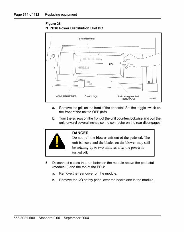
Page 314 of 432 Replacing equipment
553-3021-500 Standard 2.00 September 2004
a. Remove the grill on the front of the pedestal. Set the toggle switch on the front of the unit to OFF (left).
b. Turn the screws on the front of the unit counterclockwise and pull the unit forward several inches so the connector on the rear disengages.
5 Disconnect cables that run between the module above the pedestal (module 0) and the top of the PDU:
a. Remove the rear cover on the module.
b. Remove the I/O safety panel over the backplane in the module.
Figure 28NT7D10 Power Distribution Unit DC
DANGERDo not pull the blower unit out of the pedestal. The unit is heavy and the blades on the blower may still be rotating up to two minutes after the power is turned off.
Circuit breaker bank553-3039
System monitor
Field wiring terminal(below PDU)
PDU
Ground lugs

Replacing equipment Page 315 of 432
Communication Server 1000M and Meridian 1 Large System Maintenance
c. Disconnect the system monitor ribbon cable from the PDU.
d. Disconnect the large orange power connector (J1) from the PDU.
Note: To disconnect the power plug, you must press a latch trip on the front and rear of the plug. You may need to use a screwdriver blade against the latch trip on the front of the plug.
6 Tag and disconnect cables to the NT8D22 System Monitor. Loosen the two screws on the system monitor card and remove it from the PDU.
7 Remove the six screws that position the PDU. Carefully pull the unit straight forward and set it on the floor next to the pedestal (see Figure 29).
8 Remove the field wiring terminal block:
a. Remove the cover over the field wiring terminal block.
b. Locate the frame ground wire that runs from the field wiring terminal block to the frame ground bolt inside the pedestal. Disconnect this wire at the terminal block.
c. Carefully tag and then disconnect all input wiring to the field wiring terminal block. Take special note of any jumper wires that might be installed. It is not necessary to disconnect wiring that runs from the terminal block to the PDU.
9 Remove the four screws that secure the terminal block in place and lift it out of the pedestal.
CAUTIONDamage to EquipmentThe PDU cannot be completely removed from the pedestal until cables to the field wiring terminal block are disconnected. Label wires carefully. Improper wiring can cause system damage.

Page 316 of 432 Replacing equipment
553-3021-500 Standard 2.00 September 2004
Installing equipment
1 Install the replacement field wiring terminal block:
a. Position the replacement PDU next to the rear of the pedestal.
b. Position the replacement field wiring terminal block and replace its mounting screws.
c. Reconnect all wiring to the field wiring terminal block, including any jumpers that might have been present on the terminal block that was removed.
d. Reconnect the frame ground wire from the frame ground bolt inside the pedestal to the field wiring terminal block.
e. Replace the cover over the field wiring terminal block.
Figure 29Cabling between the PDU and the field wiring terminal block
Field wiring terminal block
(located beneaththe PDU)
553-5487
Blowerunit
PDUposition in
the pedestal
View looking down at the pedestal
Pedestal rearPDU
pulled out ofthe pedestal

Replacing equipment Page 317 of 432
Communication Server 1000M and Meridian 1 Large System Maintenance
2 Gently push the PDU into the pedestal. Replace the screws on the PDU.
Note: Be sure you push the unit straight back so the connector on the rear will seat properly with the connector for the blower unit.
3 Reconnect cables from module 0 to the PDU:
a. Attach power plug J1 and the system monitor cable.
b. Replace the I/O safety panel on the module.
c. Replace the rear cover on the module.
4 Reseat the blower unit:
a. Lift the unit slightly and slide it into the pedestal glides. Set the toggle switch to ON (right).
b. Tighten the screws on the front of the unit.
5 Insert the system monitor card into the PDU. Tighten the screws on the card. Reconnect cables to the system monitor faceplate.
6 Set all five circuit breakers on the PDU to OFF (down). Reconnect the source of DC power.
7 One at a time starting with the breaker for the blower unit, set the circuit breakers on the PDU to ON (up). Make sure the green LED lights on the power supply unit(s) in each module.
Note: On initial power up, the blower may rotate slower than expected. As the sensor detects heat, the blower will rotate more rapidly.
8 Replace the pedestal grills in the front and rear.
9 Tag defective equipment with a description of the problem and package it for return to a repair center.

Page 318 of 432 Replacing equipment
553-3021-500 Standard 2.00 September 2004
NT7D67CB Power Distribution Unit DCUse this procedure to replace the power distribution unit (PDU) for DC-powered systems.
Removing equipment
1 Disconnect the DC power at the source (not at the PDU).
2 Remove the grill on the rear of the pedestal.
3 In the rear of the pedestal, set all five circuit breakers on the PDU to OFF (down). Figure 30 shows the PDU (labeled FLTR/PWR DIST UNIT ASSY on the equipment) and the NT7D10CA System Monitor/Power Supply Assembly (labeled XSM/PWR SUPPLY ASSY on the equipment).
4 Unseat the blower unit in the front of the pedestal:
a. Remove the grill on the front of the pedestal. Set the toggle switch on the front of the unit to OFF (left).
b. Turn the screws on the front of the unit counterclockwise and pull it forward several inches (you will see the L-bracket on the rear of the unit) until the connector disengages from the rear of the PDU.
5 Disconnect cables that run between the module above the pedestal (module 0) and the PDU:
DANGERModule covers are not hinged; do not let go of the cover. Lift the cover away from the module and set it out of your work area.
DANGERDo not pull the blower unit out of the pedestal. The unit is heavy and the blades on the blower may still be rotating up to two minutes after the power is turned off.

Replacing equipment Page 319 of 432
Communication Server 1000M and Meridian 1 Large System Maintenance
a. Remove the rear cover on the module.
b. Remove the I/O safety panel over the backplane in the module.
c. Disconnect the system monitor ribbon cable from module 0.
d. Disconnect the large orange power connector (J1) from the PDU.
Note: To disconnect the power plug, you must press a latch trip on the front and rear of the plug. You may need to use a screwdriver blade against the latch trip on the front of the plug.
6 Tag and disconnect cables to the NT8D22 System Monitor faceplate.
7 Loosen the five screws that secure the NT7D10CA system monitor assembly. Pull the assembly out of the pedestal far enough to disconnect the cables to the PDU:
Figure 30NT7D67CB Power Distribution Unit DC
553-5488Filter / Power distribution unit assembly
Circuit breakers
NT7D67CB
Circuit breakers
FLTR / PWR DISTUNIT ASSY
System monitor/power supply assembly
BLO CB0
CB1
CB2
CB3
Safety cover—thefield terminal blockis behind the cover
J5J3 J6 J4
NT7D10CA

Page 320 of 432 Replacing equipment
553-3021-500 Standard 2.00 September 2004
a. Disconnect the small orange connectors (J2 on the PDU, P2 on the system monitor assembly) on the left side of the PDU.
b. Disconnect the flat white connector to the small circuit board (P1 on the PDU, J1 on the system monitor assembly) on the right side of the PDU.
8 Pull the system monitor assembly out of the pedestal along with the attached ribbon cable and set it aside until the replacement PDU is installed.
9 Remove the plastic safety cover over the terminal block on the PDU:
a. Loosen the three screws holding the cover.
b. Lift the cover up, then over the three mounting screws on the front panel of the cover.
10 Tag and disconnect all wiring to the field wiring terminal block on the PDU (see Figure 31).
CAUTIONDamage to EquipmentLabel wires carefully. Improper wiring can cause system damage.
Figure 31Field wiring terminals in the NT7D67CB PDU
553-5800
NT7D67CB FLTR / PWR DISTUNIT ASSY
BAT0,1
BAT2,3 LRTN
BATRTN0,1
BATRTN2,3
BLO CB0 CB1 CB2 CB3

Replacing equipment Page 321 of 432
Communication Server 1000M and Meridian 1 Large System Maintenance
11 Remove the PDU:
Note: When a system is shipped, a set of screws secures the leveling bracket at the rear of the PDU to protect against vibration during transit. If the shipping screws were not removed during initial installation, you must remove them now to pull the PDU out of the pedestal. Pull the blower unit all the way out of the pedestal so you can access the shipping screws on the leveling bracket.
a. Loosen the three screws that secure the PDU.
b. Remove the two vertical screws located in the rear of the PDU that hold the L-bracket to the lower pedestal.
c. Pull the PDU out of the pedestal, being careful to not chafe the cables against the pedestal.
d. Disconnect the frame ground wire from the PDU at the frame ground bolt inside the pedestal.
Installing equipment
1 Install the replacement PDU:
a. Connect the frame ground wire from the PDU to the frame ground bolt inside the pedestal.
b. Guide the connector for the power cable through the hole in the top of the pedestal (do not allow the PDU to drop).
c. Gently push the PDU into the pedestal. Position the leveling bracket (attached to the rear of the PDU) in the small opening toward the front of the pedestal. The leveling bracket will support the back of the PDU.
2 Install the NT7D10CA system monitor assembly:
a. Connect the small orange connectors (J2 on the PDU, P2 on the system monitor assembly) on the left side of the PDU.
b. Connect the flat white connector to the small circuit board (P1 on the PDU, J1 on the system monitor assembly) on the right side of the PDU.
c. Guide the connector on the free end of the system monitor ribbon cable (from J2) up through the hole in the top of the pedestal and connect it to module 0.

Page 322 of 432 Replacing equipment
553-3021-500 Standard 2.00 September 2004
d. Install and tighten the two vertical screws that attach the L-bracket to the PDU.
e. Gently push the system monitor assembly into the pedestal.
3 Tighten the screws that secure the PDU and the system monitor assembly.
4 Reconnect the remaining cables from module 0:
a. Reconnect the large orange power connector (J1).
b. Replace the I/O safety panel.
c. Replace the rear cover to the module.
5 Reconnect all external wiring to the field wiring terminal block on the PDU:
Note: All wiring to the PDU must be routed within the cable-tie saddles and under the cable restraint bar at the base of the pedestal.
a. Remove the plastic safety cover over the terminal block.
b. Connect the red BAT (–48 V) wires to the terminal block:
— for modules 0 and 1 connect to the BAT 0,1 terminal
— for modules 2 and 3 connect to the BAT 2,3 terminal
The safety ground/protective earth wires and all wiring to the block in the PDU must be neatly routed within the cable-tie saddles and under the cable restraint bar at the base of the pedestal. This ensures that there is room to install the PDU cover, safety cover, and rear grill.
c. Connect the black BATRTN (48 V return) wires to the terminal block:
— for modules 0 and 1 connect to the BATRTN 0,1 terminal
— for modules 2 and 3 connect to the BATRTN 2,3 terminal
d. Connect the orange (or white) wire to the LRTN terminal.
6 Reinstall the plastic safety cover over the terminal block.
7 Reseat the blower unit:
a. Lift the unit slightly and slide it into the pedestal glides. Set the toggle switch to ON (right).
b. Tighten the screws on the front of the unit.

Replacing equipment Page 323 of 432
Communication Server 1000M and Meridian 1 Large System Maintenance
8 Reconnect cables to the system monitor faceplate.
9 Set all five circuit breakers on the PDU to OFF (down). Reconnect the source of DC power.
10 One at a time starting with the breaker for the blower unit, set the circuit breakers on the PDU to ON (up). Make sure the green LED lights on the power supply unit(s) in each module.
Note: On initial power up the blower may rotate slower than expected. As the sensor detects heat, the blower will rotate more rapidly.
11 Replace the pedestal grills in the front and rear.
12 Tag defective equipment with a description of the problem and package it for return to a repair center.
NT7R51 Local Carrier Interface CardUse this procedure to replace a Local Carrier Interface card.
See Software Input/Output: Administration (553-3001-311) for a description of all maintenance commands, and Software Input/Output: System Messages (553-3001-411) for interpreting system messages.
Removing and replacing a Local Carrier Interface card
1 Disable the Local Carrier Interface card by logging in to the system terminal, loading the Network and Peripheral Equipment Diagnostic Program LD 32, and executing DISL loop, where loop is the actual loop number of the Local Carrier Interface card.
2 Set the ENL/DIS switch to DIS.
3 Disconnect the cable from the Local Carrier Interface card faceplate.
4 Unlatch the card locking devices by squeezing the tabs and pulling the locking devices away from the card.
DANGERModule covers are not hinged; do not let go of the cover. Lift the cover away from the module and set it out of your work area.

Page 324 of 432 Replacing equipment
553-3021-500 Standard 2.00 September 2004
5 Pull the card out of the network module and place it into an antistatic bag away from the work area.
6 Set the replacement card ENL/DIS switch to DIS.
7 Hold the replacement card by the card locking devices and insert it partially into the card guides in the module.
8 Pull the upper and lower locking devices away from the faceplate on the card and insert the card firmly into the backplane connector. Press the card locking devices firmly against the faceplate to latch the card inside the module.
9 Set the replacement card ENL/DIS switch to ENL, the Local Carrier Interface card automatically starts the self-test
10 Observe the red LED on the front panel during self-test. If it flashes three times and stays on, it has passed the test. Go to step 11. If it does not flash three times and then stays on, it has failed the test. Pull the card partially out of the module and reinsert it firmly into the module. If the problem persists, troubleshoot or replace the Local Carrier Interface card.
11 Connect the cable to the Local Carrier Interface card faceplate connector.
12 Enable the Local Carrier Interface card. Load the Network and Peripheral Equipment Diagnostic Program LD 32, and executing ENLL loop, where loop is the actual loop number of the Local Carrier Interface card.r.
13 Tag the defective card(s) with a description of the problem and prepare them for shipment to your equipment suppliers' repair depot.
NT7R52 Remote Carrier Interface CardUse this procedure to replace a Remote Carrier Interface card.
See Software Input/Output: Administration (553-3001-311) for a description of all maintenance commands, and Software Input/Output: System Messages (553-3001-411) for interpreting system messages.
DANGERModule covers are not hinged; do not let go of the cover. Lift the cover away from the module and set it out of your work area.

Replacing equipment Page 325 of 432
Communication Server 1000M and Meridian 1 Large System Maintenance
Removing and replacing a Remote Carrier Interface card
1 Load Network and Peripheral Equipment Diagnostic Program LD 32. At the > prompt, type LD 32 and press the Enter key to access the program.
2 Type DSXP x, where x is the Remote Carrier Interface card number, and press the Enter key to disable the card. The Remote Carrier Interface card is now disabled and you can remove it.
3 Unlatch the card locking devices by squeezing the tabs and pulling them away from the card.
4 Pull the card out of the IPE module or cabinet and place it into an antistatic bag away from the work area.
5 Hold the replacement card by the card locking devices and insert it partially into the card guides in the module.
6 Pull the upper and lower locking devices away from the faceplate on the card and insert the card firmly into the backplane connector. Press the card locking devices firmly against the faceplate to latch the card inside the module. The Remote Carrier Interface card automatically starts the self-test.
7 Observe the red LED on the front panel during self-test. If it flashes three times and stays on, it has passed the test. Go to step 8. If it does not flash three times and then stays on, it has failed the test. Pull the card partially out of the module and reinsert it firmly into the module. If the problem persists, troubleshoot or replace the Remote Carrier Interface card.
8 At the. prompt in the LD 32 program, type ENXP x, where x is the Remote Carrier Interface card number, and press the Enter key to enable the card. If the upper most red LED on the Remote Carrier Interface card faceplate turns off, the card is functioning correctly and is enabled. The outcome of self-test will also be indicated by LD 32 on the MMI terminal connected to the Remote Carrier Interface card. If the LED stays on, replace the card.
9 Tag the defective card(s) with a description of the problem and prepare them for shipment to your equipment suppliers' repair depot.
NT8D01 Controller CardUse this procedure to replace a controller card.

Page 326 of 432 Replacing equipment
553-3021-500 Standard 2.00 September 2004
See Software Input/Output: Administration (553-3001-311) for a description of all maintenance commands, and Software Input/Output: System Messages (553-3001-411) for interpreting system messages.
Removing equipment
1 Turn off power to the module:
— With AC power, set the associated circuit breaker on the module power supply (MPDU) to OFF (down).
Note: If there are two circuit breakers on the MPDU, the top one is associated with the module power supply, the bottom one with the ringing generator.
— With DC power, set the switch on the module power supply to OFF (down).
2 Software disable the controller card (and all cards connected to the controller):
3 Unhook the locking devices on the card; pull it out of the card cage.
Installing equipment
1 Insert the replacement card into the vacated slot and hook the locking devices.
2 Turn on power to the module:
— With AC power, set the associated circuit breaker on the MPDU to ON (up).
— With DC power, set the switch on the module power supply to ON (up).
3 Watch the controller card as it runs a series of self-tests:
DANGERModule covers are not hinged; do not let go of the cover. Lift the cover away from the module and set it out of your work area.
LD 32DSXP x “x” is the controller card number

Replacing equipment Page 327 of 432
Communication Server 1000M and Meridian 1 Large System Maintenance
— During the tests, the maintenance display on the card shows the code for each test running (see “HEX” in the Software Input/Output: System Messages (553-3001-411)). If the tests complete successfully, the display begins normal operation. If the card continuously fails a test, the code for that test is displayed.
— When IPE cards are installed, the red LED on the faceplate remains lit for 2 to 5 seconds as a self-test runs. If the self-test completes successfully, the LED flashes three times and remains lit until the card is configured and enabled in software, then the LED goes out. If the LED does not follow the pattern described or operates in any other manner (such as continually flashing or remaining weakly lit), replace the card.
4 Software enable and test the controller card (and all cards connected to the controller):
ENXP x
— If there is a problem, an NPR, NWS, or SDL system message may be produced and the red LED lights on the controller card.
— If there is no problem, exit LD 32:
****
5 Tag defective equipment with a description of the problem and package it for return to a repair center.
NT8D02, NT8D03, NT8D09, NT8D14, NT8D15, NT8D16Intelligent Peripheral Equipment Card
Use this procedure to replace the following intelligent peripheral equipment (IPE) cards:
• NT5D11 Line Side T1
• NT5D60AA CLASS Modem Card
• NT5K02 Flexible Analog Line Card
• NT5K07 Universal Trunk Card
• NT5K17 Direct Dial Inward Trunk Card
• NT5K18 Central Office Trunk Card

Page 328 of 432 Replacing equipment
553-3021-500 Standard 2.00 September 2004
• NT5K19 E&M Trunk Card
• NT5K20 Tone Detector Card
• NT5K36 Direct Inward/Direct Outward Dial Trunk Card
• NT5K48 Tone Detector Card
• NT5K70 Central Office Trunk Card
• NT5K71 Central Office Trunk Card
• NT5K72 E&M Trunk Card
• NT5K82 Central Office Trunk Card
• NT5K83 E&M Trunk Card
• NT5K84 Direct Inward Dial Trunk Card
• NT5K90 Central Office Trunk Card
• NT5K93 Central Office Trunk Card
• NT5K96 Analog Line Card
• NT5K99 Central Office Trunk Card
• NT8D02 Digital Line Card
• NT8D03 Analog Line Card
• NT8D09 Analog Message Waiting Line Card
• NT8D14 Universal Trunk Card
• NT8D15 E&M Trunk Card
• NT8D16 Digitone Receiver (DTR) Card
See Software Input/Output: Administration (553-3001-311) for a description of all maintenance commands, and Software Input/Output: System Messages (553-3001-411) for interpreting system messages.
DANGERModule covers are not hinged; do not let go of the cover. Lift the cover away from the module and set it out of your work area.

Replacing equipment Page 329 of 432
Communication Server 1000M and Meridian 1 Large System Maintenance
Removing equipment
1 Software disable the card:
You will see “NPR011” on the system terminal when the card is disabled. Busy channels will not be disabled until the call is disconnected.
2 Unhook the locking devices on the card; pull it out of the card cage.
Installing equipment
1 Set jumpers on the following replacement cards the same as on the card you removed:
NT8D14 Universal Trunk CardNT8D15 E&M Trunk Card
To check settings, see Circuit Card: Description and Installation (553-3001-211).
2 Insert the replacement card into the vacated slot and hook the locking devices.
Note: When IPE cards are installed, the red LED on the faceplate remains lit for 2 to 5 seconds as a self-test runs. If the self-test completes successfully, the LED flashes three times and remains lit until the card is configured and enabled in software, then the LED goes out. If the LED does not follow the pattern described or operates in any other manner (such as continually flashing or remaining weakly lit), replace the card.
3 Software enable the card:
ENLC l s c
a. When the process is complete, you will receive a system response.
b. Exit LD 32:
****
4 Test the card:
LD 30SHLF l s
Note: This command tests every card on the designated shelf.
LD 32DISI l s c “l s c” are loop, shelf, and card numbers
Page 330 of 432 Replacing equipment
553-3021-500 Standard 2.00 September 2004
a. If there is a problem, an NPR system message is generated and the red LED(s) on the faceplate of the card will remain lit.
b. If there is no problem, exit LD 30:
****
5 Tag defective equipment with a description of the problem and package it for return to a repair center.
NT8D04 Superloop Network Card, QPC414 Network CardUse this procedure to replace a superloop network card or network card.
See Software Input/Output: Administration (553-3001-311) for a description of all maintenance commands, and Software Input/Output: System Messages (553-3001-411) for interpreting system messages.
DANGERModule covers are not hinged; do not let go of the cover. Lift the cover away from the module and set it out of your work area.
CAUTIONService InterruptionAll services on a loop are interrupted while the loop is disabled.

Replacing equipment Page 331 of 432
Communication Server 1000M and Meridian 1 Large System Maintenance
Removing equipment
1 Check the status of each loop on the network or superloop network card:
— If the response is DSBL for the loop(s), go to step 2 on page 331.
— If there are responses other than DSBL, see “LD 32” in the Software Input/Output: Administration (553-3001-311) for an interpretation.
2 Set the ENB/DIS switch to DIS.
3 Tag and disconnect cables to the card you are removing.
4 Unhook the locking devices on the card; pull it out of the card cage.
Installing equipment
1 Set the ENB/DIS switch to DIS on the replacement card.
Note: On a replacement QPC414, set jumpers the same as on the card you removed. If there is a vintage change, be sure to check Circuit Card: Description and Installation (553-3001-211) for any differences.
2 Insert the replacement card into the vacated slot and hook the locking devices.
3 Connect cables to the replacement card.
4 Set the ENB/DIS switch to ENB on the replacement card.
5 Software enable each loop on the card:
ENLL loop
a. When the process is complete, you will receive a system response.
b. The card is tested automatically when all loops are enabled.
c. If there is a problem, an NWS system message is generated and the red LED on the faceplate of the card will flash (on the NT8D04) or be steadily lit (on the QPC414).
d. If there is no problem, exit LD 32:
****
LD 32STAT loop “loop” is a loop number

Page 332 of 432 Replacing equipment
553-3021-500 Standard 2.00 September 2004
6 Tag defective equipment with a description of the problem and package it for return to a repair center.
NT8D06, NT8D21, NT8D29 Power Supply ACUse this procedure to replace AC power supplies:
• NT8D06 PE Power Supply AC
• NT8D21 Ringing Generator AC
• NT8D29 CE Power Supply AC
Removing equipment
1 Turn off power to the module power supply:
— If there is a Module Power Distribution Unit (MPDU), set the circuit breaker(s) on the associated MPDU to OFF (down).
Note: If there are two circuit breakers on the MPDU, the top one is associated with the module power supply, the bottom one with the ringing generator (see Figure 32).
— If there is no MPDU, set the switch on the power supply faceplate to OFF (down).
2 Unhook the locking devices on the power supply. Wait at least 5 minutes, then pull the power supply out of the card cage.
DANGERModule covers are not hinged; do not let go of the cover. Lift the cover away from the module and set it out of your work area.
DANGER OF ELECTRIC SHOCKPower must discharge. Wait five full minutes before you remove the power supply from the module.

Replacing equipment Page 333 of 432
Communication Server 1000M and Meridian 1 Large System Maintenance
Installing equipment
1 Insert the replacement power supply into the vacated slot and hook the locking devices.
Note 1: If there is a switch on the power supply, set the switch to OFF (down) before you insert the power supply.
Note 2: On a replacement NT8D21, set option strapping the same as on the one you removed. If there is a vintage change, be sure to check Circuit Card: Description and Installation (553-3001-211) for any differences.
2 Turn on power to the module power supply. The green LED on the power supply should light and stay lit:
— If there is an MPDU, set the circuit breaker(s) to ON (up).
— If there is no MPDU, set the power supply switch to ON (up).
3 Tag defective equipment with a description of the problem and package it for return to a repair center.
Figure 32Dual circuit breaker and associated module power supplies
IntelligentPeripheral Equipment
SuperloopShelf
IPEPE Module
PE Pwr Sup Rng Gen0 2 3 4 5 6 7 Cont 9 11 12 13 151 8 14
553-5376
10
Module power supply
MPDU
Ringinggenerator
Page 334 of 432 Replacing equipment
553-3021-500 Standard 2.00 September 2004
NT8D17 Conference/TDS CardThe conference/TDS card provides conference functions on one loop and both tone and digit switch (TDS) and multi frequency sender (MFS) functions on a second loop. Use this procedure to replace a conference/TDS card.
See Software Input/Output: Administration (553-3001-311) for a description of all maintenance commands, and Software Input/Output: System Messages (553-3001-411) for interpreting system messages.
Removing equipment
1 Software disable the conference/TDS card:
Note: You must use the command DISX to disable both loops and all hardware functions. Disabling loops with the command DISL prevents software from using the loops but does not disable the card.
2 Set the ENB/DIS switch to DIS.
3 Unhook the locking devices on the card; pull it out of the card cage.
Installing equipment
1 Set the ENB/DIS switch to DIS on the replacement card.
2 Set option switches and jumpers on the replacement card the same as on the card you removed. If there is a vintage change, be sure to check Circuit Card: Description and Installation (553-3001-211) for any differences.
DANGERModule covers are not hinged; do not let go of the cover. Lift the cover away from the module and set it out of your work area.
LD 34 or LD 38 or LD 46DISX loop In LD 38 “loop” is the conference loop that is the
odd loop of the conference/TDS loop pair. In LD 34 and LD 46 “loop” is the TDS/MFS loop that is the even loop of the conference/TDS loop pair.

Replacing equipment Page 335 of 432
Communication Server 1000M and Meridian 1 Large System Maintenance
3 Insert the replacement card into the vacated slot and hook the locking devices. Both red LEDs should flash three times and remain lit if the card is good.
4 Set the ENB/DIS switch to ENB on the replacement card.
5 Software enable the card:
Note: You must enable the card with the command ENLX. Enabling the loops with the command ENLL does not enable the card.
6 Test each loop on the card (when each test completes, enter ****):
a. Test TDS capability:
b. Test Conference capability:
c. Test MFS capability:
d. If there is a problem, a TDS, CNF, or MFS system message is generated and the appropriate red LED lights on the card faceplate.
7 Tag defective equipment with a description of the problem and package it for return to a repair center.
NT8D22 System MonitorUse this procedure to replace the system monitor.
ENLX loop This prompt is available in LD 34, LD 38, and LD 46. Use the appropriate loop number (see step 1 on page 334 in “Removing equipment” on page 334).
LD 34TDS loop “loop” is an even loop number
LD 38CNFC loop “loop” is an odd loop number
LD 46MFS loop “loop” is an even loop number

Page 336 of 432 Replacing equipment
553-3021-500 Standard 2.00 September 2004
See Software Input/Output: Administration (553-3001-311) for a description of all maintenance commands, and Software Input/Output: System Messages (553-3001-411) for interpreting system messages.
Removing equipment
1 Remove the grill on the rear of the pedestal.
2 Tag and disconnect cables to the system monitor. Figure 33 shows the location of the system monitor in the rear of an AC-power pedestal.
CAUTIONService InterruptionBe sure to follow the steps in this procedure in the order shown. Removing the system monitor before disconnecting cables may result in loss of power and interruption of telephone service.
Figure 33NT8D22 System Monitor in an AC-power pedestal
Mounting screwSystem monitor
Main circuitbreaker
Power distributionunit—AC Mounting screws
553-3013

Replacing equipment Page 337 of 432
Communication Server 1000M and Meridian 1 Large System Maintenance
3 Loosen the two screws on the card and pull it out of the slot.
Note: If a slave is removed, the master considers that slave and all slaves with a higher address as disabled. For example, if the slave designated “XSM 2” is disabled, the master also reports slaves 3, 4, and up are disabled.
Installing equipment
1 Set option switches on the replacement card the same as on the card you removed. If there is a vintage change, be sure to check Communication Server 1000M and Meridian 1: Large System Installation and Configuration (553-3021-210) for any differences.
2 Insert the replacement card into the vacated slot and tighten the two screws on the front of the card.
3 Connect cables to the replacement card.
4 Replace the grill on the rear of the pedestal.
5 Test the system monitor:
LD 37STAT XSM
— If a single or master system monitor was replaced successfully, you will receive system message “PWR000 XSMC 00 0 0.”
— If a slave was replaced successfully, you will receive “PWR053 XSMC xx 0 0” (“x” is the system monitor address).
— If there is a problem with a slave, you will receive system message “PWR013 XSMC xx 0 0.”
— If there is no problem, exit LD 37:
****
6 Tag defective equipment with a description of the problem and package it for return to a repair center.
NT8D41 Dual or Quad Port Serial Data Interface cardThe serial data interface (SDI) paddle board attaches to the rear of the backplane in an NT6D39 CPU/Network Module. Use this procedure to replace an SDI paddle board.

Page 338 of 432 Replacing equipment
553-3021-500 Standard 2.00 September 2004
See Software Input/Output: Administration (553-3001-311) for a description of all maintenance commands, and Software Input/Output: System Messages (553-3001-411) for interpreting system messages.
Removing equipment
1 Software disable each port on the SDI paddle board:
2 Remove the rear cover on the module.
3 Remove the I/O safety panel by turning the screws on each side. Set the cover aside.
4 Set the ENB/DIS switch to the disable position (down) on the paddle board.
5 Tag and disconnect cables to the paddle board you are removing (connector J1 for port 1, connector J2 for port 2).
DANGERModule covers are not hinged; do not let go of the cover. Lift the cover away from the module and set it out of your work area.
CAUTIONLoss of DataIf the system terminal is assigned to the SDI being replaced, assign it to another port before this SDI is disabled.
LD 37DIS TTY x “x” is the number of the interface device attached to
the port
CAUTIONService InterruptionTo avoid interrupting service, set ENB/DIS switches to DIS before disconnecting or connecting cables.

Replacing equipment Page 339 of 432
Communication Server 1000M and Meridian 1 Large System Maintenance
6 Pull the paddle board out of the connector on the backplane.
Installing equipment
1 Set the ENB/DIS switch to the disable position (down) on the replacement paddle board.
2 Set option switches on the replacement paddle board the same as on the board you removed. If there is a vintage change, be sure to check Circuit Card: Description and Installation (553-3001-211) for any differences.
3 Plug the replacement paddle board into the vacated connector on the backplane.
4 Connect cables to the replacement paddle board.
5 Set the ENB/DIS switch to the enable position (up) on the replacement paddle board.
6 Replace the I/O safety panel. Replace the rear cover on the module.
7 Software enable and test each port on the paddle board:
ENL TTY xTTY x
— If there is a problem, an IOD system message is generated and the red LED lights on the faceplate of the card.
— If there is no problem, exit LD 37:
****
8 Tag defective equipment with a description of the problem and package it for return to a repair center.
NT8D46AC Thermostat HarnessUse this procedure to replace the thermostat harness located in the top cap of each column.
DANGERModule covers are not hinged; do not let go of the cover. Lift the cover away from the module and set it out of your work area.

Page 340 of 432 Replacing equipment
553-3021-500 Standard 2.00 September 2004
Removing equipment
1 Disconnect the system monitor from the circuit breaker system:
a. Remove the grill on the rear of the column pedestal.
b. Loosen the two screws on the system monitor and pull it out a few inches.
2 Disconnect power to the top cap:
a. Remove the rear cover on the module below the top cap.
b. Remove the I/O safety panel over the backplane.
c. At the top of the rear of the module, disconnect the connector from the module power harness.
d. Disconnect the pin headers on connector J2 on the backplane; disconnect the ribbon cable connector.
3 Remove the top cap:
a. Remove air exhaust grills at the front and rear of the top cap (see Figure 34). Pull forward on the two clips underneath the front edge of each grill and lift up to remove the grill.
b. Use a 5/16” socket wrench to remove the six bolts that secure the top cap and perforated panel (see Figure 35). Lift off the top cap only.
4 Remove the thermostat harness:
Note: The column LED and LED wiring are part of the thermostat harness.
a. Pull the LED ring away from the LED mounting bracket (see Figure 36). You may need to loosen it with a standard screwdriver.
b. Push the LED back completely out of the collar on the LED mounting bracket.
CAUTIONService Interruptionf the system monitor is not unseated, column operation will shut down when the thermostat harness is disconnected.

Replacing equipment Page 341 of 432
Communication Server 1000M and Meridian 1 Large System Maintenance
c. Remove the LED ring by pulling it forward over the LED. Keep the ring handy; you will use it with the replacement equipment.
d. Remove the screw that secures the perforated panel at the LED mounting bracket.
e. Slide the perforated panel slightly to the left (looking at it from the rear of the column). Lift the panel and turn it over.
Figure 34Air exhaust grills on the top cap
Figure 35Top cap assembly
Air exhaust grillAir exhaust grillTop cap
Module Clips553-5886
Mounting bolts
LED
553-3038
Screw for LED bracketon perforated panel
Top cap
Front of column

Page 342 of 432 Replacing equipment
553-3021-500 Standard 2.00 September 2004
f. Clip all cable ties that secure the thermostat harness. Be careful not to damage other wiring (such as the air probe harness).
g. Pull the LED through the rubber grommet at the front of the perforated panel.
h. Remove the screws (two each) that secure the thermostats. Remove the thermostats and wiring (see Figure 37).
Figure 36Mounting for the column LED
Figure 37Thermostat harness
Mountingbracket
LED
Collar (front)
Collar(back)
Perforated panelscrew
LEDring
553-3048
553-5884
Thermostatwiring
To connector J2
Front
Thermostats
Grommet
LED
Perforatedpanel
(bottom)

Replacing equipment Page 343 of 432
Communication Server 1000M and Meridian 1 Large System Maintenance
Installing equipment
1 Install the replacement thermostat harness:
a. Position the replacement thermostats and install the screws.
b. Push the LED through the rubber grommet.
c. Route the thermostat wiring on the perforated panel. At the rear edge of the panel, route the wires with wiring for the air probe harness. Secure loose wiring to the perforated panel with cable ties.
2 Turn the perforated panel over. Slide it slightly to the right (at the rear of the column) so it is in a secure position. Position wiring from the perforated panel so it rests in the cable well next to the orange connector at the rear of the module (see Figure 38). Position the perforated panel and install the screw that secures it at the LED mounting bracket.
a. Slide the LED ring over the LED (see Figure 39). The ring will hang loosely at this point.
b. Gently push the LED forward completely through the collar on the LED mounting bracket.
c. Push the LED ring into position over the back of the collar and tight against the LED mounting bracket.
3 Install the top cap:
a. Position the top cap and install the six bolts that secure the top cap and perforated panel.
b. Install the air exhaust grills at the front and rear of the top cap.
Figure 38Routing the thermostat harness from the top cap
Bracket
553-5889
Cable well
Top ofmodule
Orange connector
View at rear of module
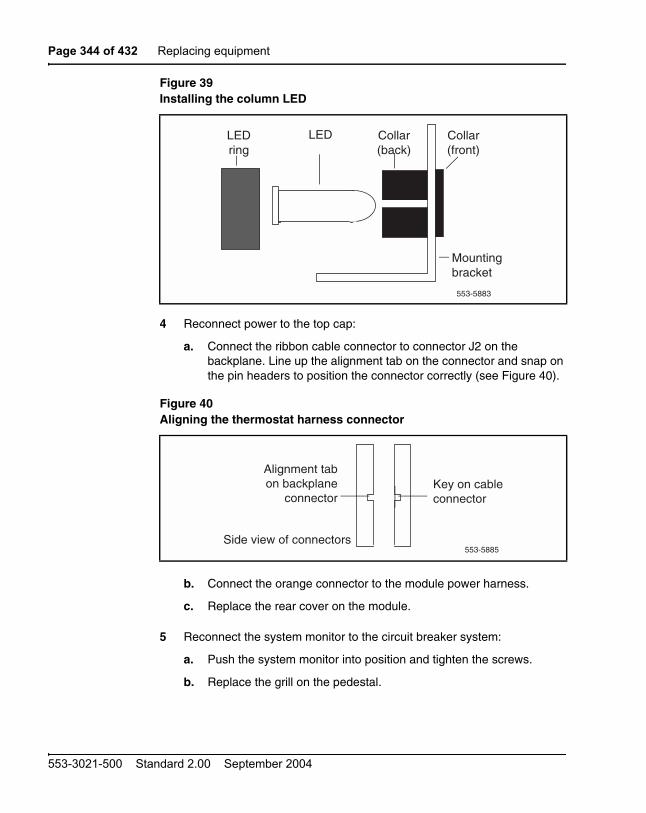
Page 344 of 432 Replacing equipment
553-3021-500 Standard 2.00 September 2004
4 Reconnect power to the top cap:
a. Connect the ribbon cable connector to connector J2 on the backplane. Line up the alignment tab on the connector and snap on the pin headers to position the connector correctly (see Figure 40).
b. Connect the orange connector to the module power harness.
c. Replace the rear cover on the module.
5 Reconnect the system monitor to the circuit breaker system:
a. Push the system monitor into position and tighten the screws.
b. Replace the grill on the pedestal.
Figure 39Installing the column LED
Figure 40Aligning the thermostat harness connector
Collar(back)
LEDLEDring
Mounting bracket
553-5883
Collar(front)
Side view of connectors
Alignment tabon backplane
connector
553-5885
Key on cableconnector

Replacing equipment Page 345 of 432
Communication Server 1000M and Meridian 1 Large System Maintenance
6 Tag defective equipment with a description of the problem and package it for return to a repair center.
NT8D46AM, NT8D46DC Air Probe HarnessUse this procedure to replace the air probe harness located in the top cap of each column.
Removing equipment
1 Disconnect the air probe harness plug:
a. Remove the rear cover on the module below the top cap.
b. Remove the I/O safety panel over the backplane.
c. At the top of the rear of the module, disconnect the orange connector from the module power harness.
2 Remove the top cap:
a. Remove air exhaust grills at the front and rear of the top cap (see Figure 41). Pull forward on the two clips underneath the front edge of each grill and lift up to remove the grill.
b. Use a 5/16” socket wrench to remove the six bolts that secure the top cap and perforated panel (see Figure 42). Lift off the top cap.
DANGERModule covers are not hinged; do not let go of the cover. Lift the cover away from the module and set it out of your work area.
Figure 41Air exhaust grills in the top cap
Air exhaust grillAir exhaust grillTop cap
Module Clips553-5886
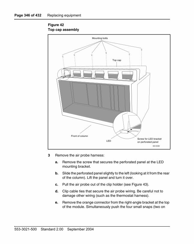
Page 346 of 432 Replacing equipment
553-3021-500 Standard 2.00 September 2004
3 Remove the air probe harness:
a. Remove the screw that secures the perforated panel at the LED mounting bracket.
b. Slide the perforated panel slightly to the left (looking at it from the rear of the column). Lift the panel and turn it over.
c. Pull the air probe out of the clip holder (see Figure 43).
d. Clip cable ties that secure the air probe wiring. Be careful not to damage other wiring (such as the thermostat harness).
e. Remove the orange connector from the right-angle bracket at the top of the module. Simultaneously push the four small snaps (two on
Figure 42Top cap assembly
Mounting bolts
LED
553-3038
Screw for LED bracketon perforated panel
Top cap
Front of column

Replacing equipment Page 347 of 432
Communication Server 1000M and Meridian 1 Large System Maintenance
each side) on the connector to release it from the bracket (see Figure 44).
Installing equipment
1 Install the replacement air probe harness:
a. Gently push the air probe into the clip holder.
b. Route the air probe wiring on the perforated panel. At the rear edge of the panel, route the wires with wiring for the thermostat harness. Secure loose cabling to the perforated panel with cable ties.
c. Turn the perforated panel over. Slide it slightly to the right (at the rear of the column) so it is in a secure position. Position wiring from the perforated panel so it rests in the cable well next to the orange connector at the rear of the module (see Figure 45).
d. Insert the orange connector into the right-angle bracket at the top of the module. Simultaneously push the four small snaps on the connector to insert it.
Figure 43Air probe harness
Figure 44Connector for the air probe harness
553-5887
Air probewiringTo orange connector
Front
Perforatedpanel
(bottom)
Air probe
553-5888
Orange connector
Push here
Push here
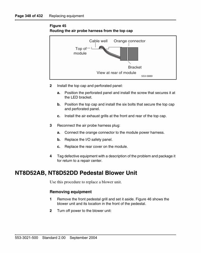
Page 348 of 432 Replacing equipment
553-3021-500 Standard 2.00 September 2004
2 Install the top cap and perforated panel:
a. Position the perforated panel and install the screw that secures it at the LED bracket.
b. Position the top cap and install the six bolts that secure the top cap and perforated panel.
c. Install the air exhaust grills at the front and rear of the top cap.
3 Reconnect the air probe harness plug:
a. Connect the orange connector to the module power harness.
b. Replace the I/O safety panel.
c. Replace the rear cover on the module.
4 Tag defective equipment with a description of the problem and package it for return to a repair center.
NT8D52AB, NT8D52DD Pedestal Blower UnitUse this procedure to replace a blower unit.
Removing equipment
1 Remove the front pedestal grill and set it aside. Figure 46 shows the blower unit and its location in the front of the pedestal.
2 Turn off power to the blower unit:
Figure 45Routing the air probe harness from the top cap
Bracket
553-5889
Cable well
Top ofmodule
Orange connector
View at rear of module

Replacing equipment Page 349 of 432
Communication Server 1000M and Meridian 1 Large System Maintenance
— With AC power, set the circuit breaker on the front of the unit to OFF (down).
— With DC power, set the toggle switch on the front of the unit to OFF (left).
3 Loosen the two screws on the front of the blower unit by turning them counterclockwise.
4 Grasp the lip at the top edge of the blower unit. Slide the unit out of the glides and onto the bottom ledge of the pedestal. Lift the unit out of the pedestal.
Note: Store the blower unit in an upright position.
Figure 46NT8D52 Blower Unit
DANGERImpellers in the blower unit do not stop instantly when the power is turned off. Wait two full minutes before you remove the unit.

Page 350 of 432 Replacing equipment
553-3021-500 Standard 2.00 September 2004
Installing equipment
1 Set the replacement blower unit on the bottom ledge of the pedestal.
2 Tilt the back of the blower unit up slightly so it will slide into the pedestal glides (you may need to lift the unit). Gently push the unit into position.
3 Tighten the screws on the front of the unit.
4 Turn on power to the blower unit:
— With AC power, set the circuit breaker to ON (up).
— With DC power, set the toggle switch to ON (right).
Note: On initial power up the blower may rotate slower than expected. As the sensor detects heat, the blower will rotate more rapidly.
5 Fit the grill into the holes in the bottom ledge of the pedestal. Push the grill back into a locked position.
6 Tag defective equipment with a description of the problem and package it for return to a repair center.
NT8D53CA Power Distribution Unit ACUse this procedure to replace the power distribution unit (PDU) for AC-powered systems.
Removing equipment
1 Turn off power at the distribution box. If the column is not hardwired, unplug the power cable.
2 Remove the grill on the rear of the pedestal. Figure 47 shows the location of the unit in the rear of the pedestal.
3 Loosen the three mounting screws that secure the field wiring access plate. Lift the plate over the screws and set it aside.
DANGERModule covers are not hinged; do not let go of the cover. Lift the cover away from the module and set it out of your work area.

Replacing equipment Page 351 of 432
Communication Server 1000M and Meridian 1 Large System Maintenance
4 Tag and disconnect wiring to the LRTN, GND, L2, and L1 connections on the right side of the field wiring terminal (see Figure 48). Push all the wires down into the empty area under the pedestal
.
5 Tag and disconnect cables to the NT8D22 System Monitor. Loosen the two retaining screws on the system monitor. Remove the card.
6 Disconnect cables to the module above the pedestal (module 0):
Figure 47NT8D53CA Power Distribution Unit AC
CAUTIONDamage to EquipmentLabel wires carefully. They must be reconnected correctly or the system may be damaged.
Mounting screwSystem monitor
Main circuitbreaker
Power distributionunit—AC Mounting screws
553-3013

Page 352 of 432 Replacing equipment
553-3021-500 Standard 2.00 September 2004
a. Remove the rear cover on the module.
b. Remove the I/O safety panel over the backplane in the module.
c. Disconnect the power plug (J1) and system monitor ribbon cable to the module.
Note: To disconnect the power plug, you must press a latch trip on the front and rear of the plug. You may need to use a screwdriver blade against the latch trip on the front of the plug.
7 Remove the six screws that position the PDU. Carefully pull the unit straight forward out of the pedestal.
Installing equipment
1 Set the main circuit breaker on the replacement PDU to OFF (down).
2 Position the replacement PDU and gently push it into the pedestal.
Note: Be sure you push the unit straight back, so the connector on the rear will seat properly with the blower unit connector. It may be easier to position the PDU if you temporarily pull the blower unit out several inches.
3 Reconnect cables to module 0:
a. Attach power plug J1 and the system monitor cable.
b. Replace the I/O safety panel.
c. Replace the rear cover.
Figure 48Connections at the field wiring terminal
J3 J5 J6 J4
553-3086
LRTN
GND
L2
L1
To LREPDU

Replacing equipment Page 353 of 432
Communication Server 1000M and Meridian 1 Large System Maintenance
4 Insert the system monitor. Tighten the screws on the card. Reconnect cables to the system monitor faceplate.
5 Connect wiring to the right side of the field wiring terminal.
6 Position the field wiring access plate over the three mounting screws. Tighten the screws.
7 Turn on power at the distribution box or plug in the power cable.
8 Set the main circuit breaker to ON (up).
9 Replace the pedestal grill.
10 Tag defective equipment with a description of the problem and package it for return to a repair center.
NT8D56AA, NT8D56AC, NT8D57 Module Power Distribution Unit
Use this procedure to replace the following module power distribution units (MPDUs):
• NT8D56AA single-breaker MPDU for the NT8D29 CE Power Supply AC
• NT8D56AC single-breaker MPDU for the NT7D14 CE/PE Power Supply AC
• NT8D57 dual-breaker MPDU for the NT8D06 PE Power Supply AC and NT8D21 Ringing Generator AC
DANGERModule covers are not hinged; do not let go of the cover. Lift the cover away from the module and set it out of your work area.
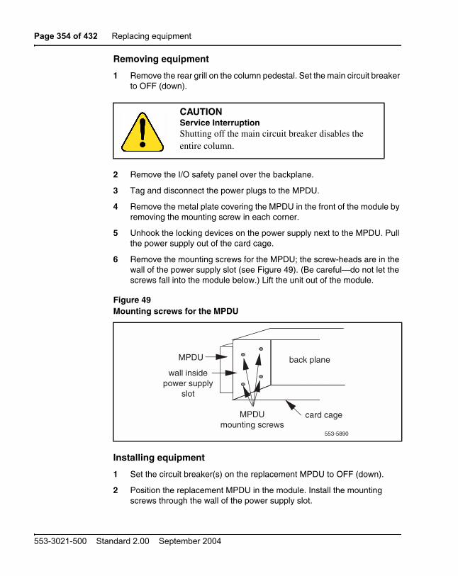
Page 354 of 432 Replacing equipment
553-3021-500 Standard 2.00 September 2004
Removing equipment
1 Remove the rear grill on the column pedestal. Set the main circuit breaker to OFF (down).
2 Remove the I/O safety panel over the backplane.
3 Tag and disconnect the power plugs to the MPDU.
4 Remove the metal plate covering the MPDU in the front of the module by removing the mounting screw in each corner.
5 Unhook the locking devices on the power supply next to the MPDU. Pull the power supply out of the card cage.
6 Remove the mounting screws for the MPDU; the screw-heads are in the wall of the power supply slot (see Figure 49). (Be careful—do not let the screws fall into the module below.) Lift the unit out of the module.
Installing equipment
1 Set the circuit breaker(s) on the replacement MPDU to OFF (down).
2 Position the replacement MPDU in the module. Install the mounting screws through the wall of the power supply slot.
CAUTIONService InterruptionShutting off the main circuit breaker disables the entire column.
Figure 49Mounting screws for the MPDU
MPDUmounting screws
MPDU
wall inside power supply
slot
553-5890
back plane
card cage

Replacing equipment Page 355 of 432
Communication Server 1000M and Meridian 1 Large System Maintenance
3 Reinsert the power supply and hook the locking devices.
4 Position the metal plate in front of the MPDU and install the mounting screw in each corner.
5 Connect the power plugs to the rear of the MPDU.
6 Position the I/O safety panel. Tighten the screws.
7 Set the circuit breaker(s) on the replacement MPDU to ON (up).
8 Reset the main circuit breaker in the column pedestal to ON (up) and replace the pedestal grill.
9 Tag defective equipment with a description of the problem and package it for return to a repair center.
NT8D3503/NT8D3507 Network Module Card CageThe NT8D3503 Network Module Card Cage uses BTUs, however, the NT8D3507 Network Module Card Cage does not use BTUs, it uses hybrid terminators that are an integral part of the backplane. To replace a defective backplane in an NT8D35 Network Module, you must replace the card cage. Use this procedure to replace the Network Module card cage.
Connect groups 1 through 7: shelf 0 to shelf 1
On the back of each Network module backplane are five connectors: A, B, C, D and E. See Figure 50 on page 357. The connectors from shelf 0 of each Network group 1 through 7 must be connected to the connectors in shelf 1 of the same Network group.
Note: In North American systems, these connections are made in the factory. In shipments outside North America, the Network shelves are shipped separately. These connections must be made in the field
DANGERModule covers are not hinged; do not let go of the cover. Lift the cover away from the module and set it out of your work area.

Page 356 of 432 Replacing equipment
553-3021-500 Standard 2.00 September 2004
This connection is NOT made for Network group 0 in the Core/Net modules.
1 Connect an NT8D99AB cable from the A connector in shelf 0 of Network group 1 to the A connector in shelf 1 Network group 1.
2 Connect the B connector in shelf 0 to the B connector in shelf 1.
3 Connect the C connector in shelf 0 to the C connector in shelf 1.
4 Connect the D connector in shelf 0 to the D connector in shelf 1.
5 Connect the E connector in shelf 0 to the E connector in shelf 1.
6 Connect the A, B, C, D, and E connectors between shelf 0 and shelf 1 for all other Network groups in the system (except group 0)
Note: All connections are made with an NT8D99AB cable.

Replacing equipment Page 357 of 432
Communication Server 1000M and Meridian 1 Large System Maintenance
Figure 50Network shelf 0 to shelf 1 backplane connections (groups 1 through 7)
Connect the Network modules to the Core/Net modules
Each Network shelf contains one 3PE card. These 3PE cards are connected to the Termination Panel in the back of the Core/Net shelves.
A
B
C
D
E
A
B
C
D
E
553-9584
Network backplane:shelf 0
Network backplane:shelf 1
NT8D99AB cable

Page 358 of 432 Replacing equipment
553-3021-500 Standard 2.00 September 2004
Figure 51 on page 358, Figure 52 on page 359 and Figure 52 on page 359 show the location of the Termination Panel and 3PE cables on the Core/Net backplane.
.
cCNI slot and port assignments
Each system contains a minimum of one and a maximum of four CNI cards. Each cCNI card contains two ports to support up to two Network groups.
Figure 513PE Termination Panel in the Core/Net module (top view)
PS
Con
fere
nce/
TD
S
Net
wor
k ca
rd
Sup
erlo
op N
etw
ork
card
NE
T
Sup
erlo
op N
etw
ork
card
NE
T
Sup
erlo
op N
etw
ork
card
Per
iphe
ral S
igna
ling
card
3-P
ort E
xten
der
card
cCN
I S
lot c
9cC
NI
Slo
t c10
cCN
I S
lot c
11cC
NI
Slo
t c12
Sys
Util
CP
PII
MM
DU
Termination Panel
cCN
I Tra
nsiti
on
cCN
I Tra
nsiti
on
cCN
I Tra
nsiti
on
cCN
I Tra
nsiti
on
Sys
Util
Tra
nsiti
on
553-9488
IGS
/FIJ
I car
d
cCNI Transition Cables(factory installed)
Port 9-0:direct connection
to cCNI Transition Card(factory installed)
NE
T
NT8D76 cables:to 3PE cards
in Network shelves(customer installed)

Replacing equipment Page 359 of 432
Communication Server 1000M and Meridian 1 Large System Maintenance
cCNI cards are identified by slot and port. Each port is assigned in software to a specific Network group. Use the System Layout Plan to determine the connections for your system.
• Each 3PE card has two faceplate connections: J3 and J4. Two cables are used for each card.
• 3PE cards in Network shelves “0” are connected to the 3PE Termination Panel in Core/Net 0.
• 3PE cards in Network shelves “1” are connected to the 3PE Termination Panel in Core/Net 1.
Figure 52Core/Net backplane (rear view)
GNDVCC
+ 12
GND
GND
VCC
IDE
SE
CO
ND
AR
Y C
HA
NN
EL
FLO
PPY
DR
IVE
12
553-9487
SYS UTILTRANS
SECURITY
DISPLAYPANEL
XSM
cCNITRANS
cCNITRANS
cCNITRANS
cCNITRANS
3PE connection tocCNI transition card
Slot 9-0(factory installed)
cCNI Transition cards
and cables(factory installed)
3PE termination panel
9101112cCNI slots:

Page 360 of 432 Replacing equipment
553-3021-500 Standard 2.00 September 2004
Figure 533PE Termination Panel (rear module view)
553-9529
3PE TerminationPanel
cCNI to Termination panel
cables (factory installed)
Termination Panel to 3PE card cables
Install SDI Paddle Boardbefore connecting 3PE cables
Route the TerminationPanel to 3PE card cables
throught the Network ModuleAccess Hole

Replacing equipment Page 361 of 432
Communication Server 1000M and Meridian 1 Large System Maintenance
Table 38 on page 361 specifies the default Network group assignments for each cCNI slot and port. These designations can be changed in software if necessary.
cCNI to 3PE Termination Panel cable connections
The cCNI slot and port connections are labeled on the 3PE Termination Panel. See Figure 54 on page 362. Each 3PE card is connected with two cables: one to J3 and one to J4. Table 38 on page 361 specifies the Network group that connects to each slot.
Connect the 3PE cables to the 3PE Termination Panels
Two NT8D76 cables connect from J3 and J4 of each 3PE faceplate to the 3PE Termination Panel. See Figure 55 on page 364.
Refer to Table 38 on page 361 for cCNI port and slot assignments. Connect shelf 0 3PE cards to the Core/Net 0 panel; connect shelf 1 3PE cards to the Core/Net 1 panel. The 3PE cables for Network group 0 are factory installed.
Table 38cCNI Network group designations
cCNI card slot
cCNI card port
3PE Termination Panel label
Connected to Network
group
c9 0 N/A (factory installed directly to the Core/Net backplane)
0
c9 1 Port 9-1 1
c10 0 Port 10-0 2
c10 1 Port 10-1 3
c11 0 Port 11-0 4
c11 1 Port 11-1 5
c12 0 Port 12-0 6
c12 1 Port 12-1 7
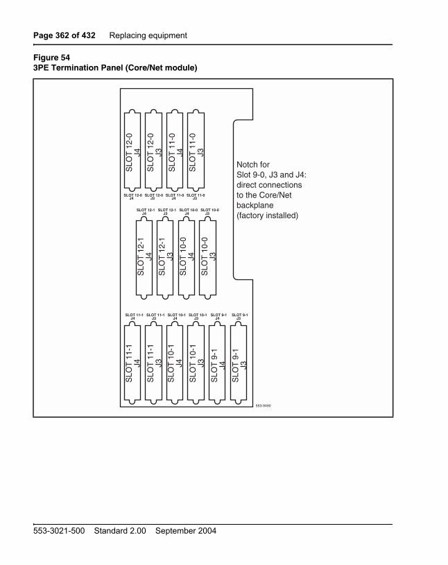
Page 362 of 432 Replacing equipment
553-3021-500 Standard 2.00 September 2004
Figure 543PE Termination Panel (Core/Net module)
SLOT 12-1 SLOT 12-1 SLOT 10-0SLOT 10-0J4 J3 J4 J3
SLOT 12-0 SLOT 12-0 SLOT 11-0 SLOT 11-0J4 J3 J4 J3
SLOT 10-1J3
SLOT 11-1J4
SLOT 11-1J3
SLOT 10-1J4
SLOT 9-1J4
SLOT 9-1J3
553-9490
Notch forSlot 9-0, J3 and J4:direct connections to the Core/Net backplane(factory installed)
SLO
T 1
2-0
J4
SLO
T 1
2-0
J3
SLO
T 1
1-0
J4
SLO
T 1
1-0
J3
SLO
T 1
2-1
J4
SLO
T 1
2-1
J3
SLO
T 1
0-0
J4
SLO
T 1
0-0
J3
SLO
T 1
1-1
J4
SLO
T 1
1-1
J3
SLO
T 1
0-1
J4
SLO
T 1
0-1
J3
SLO
T 9
-1J4
SLO
T 9
-1J3

Replacing equipment Page 363 of 432
Communication Server 1000M and Meridian 1 Large System Maintenance
Connect the Network shelf 0 3PE cards to Core/Net 0
1 Connect a NT8D76 cable of the appropriate length from J3 on the 3PE card faceplate in Network group 1, shelf 0 to the Port 9-1, J3 connection on the 3PE Termination Panel in Core/Net 0.
2 Connect a NT8D76 cable of the appropriate length from J4 on the 3PE card faceplate in Network group 1, shelf 0 to the Port 9-1, J4 connection on the 3PE Termination Panel in Core/Net 0.
3 Connect a NT8D76 cable of the appropriate length from J3 on the 3PE card faceplate in Network group 2, shelf 0 to the Port 10-0, J3 connection on the 3PE Termination Panel in Core/Net 0.
4 Connect a NT8D76 cable of the appropriate length from J4 on the 3PE card faceplate in Network group 2, shelf 0 to the Port 10-0, J4 connection on the 3PE Termination Panel in Core/Net 0.
5 Install the remaining cables according to the assignments in Table 38 on page 361.
Connect the Network shelf 1 3PE cards to Core/Net 1
1 Connect a NT8D76 cable of the appropriate length from J3 on the 3PE card faceplate in Network group 1, shelf 1 to the Port 9-1, J3 connection on the 3PE Termination Panel in Core/Net 1.
2 Connect a NT8D76 cable of the appropriate length from J4 on the 3PE card faceplate in Network group 1, shelf 1 to the Port 9-1, J4 connection on the 3PE Termination Panel in Core/Net 1.
3 Connect a NT8D76 cable of the appropriate length from J3 on the 3PE card faceplate in Network group 2, shelf 1 to the Port 10-0, J3 connection on the 3PE Termination Panel in Core/Net 1.
4 Connect a NT8D76 cable of the appropriate length from J4 on the 3PE card faceplate in Network group 2, shelf 1 to the Port 10-0, J4 connection on the 3PE Termination Panel in Core/Net 1.
5 Install the remaining cables according to the assignments in Table 38 on page 361.
NT8D3703 IPE Module Card CageTo replace a defective backplane in an NT8D37 IPE Module, you must replace the card cage. Use this procedure to replace the IPE Module card cage.

Page 364 of 432 Replacing equipment
553-3021-500 Standard 2.00 September 2004
Figure 55Example of 3PE faceplate to 3PE Termination Panel connection
CE Module Net
Common Equipment
1 2 3 4 5 6 7 8 9 10 11 12 13 14CE Pwr Sup
3-P
ort E
xten
der
Perip
hera
l Sign
aling
Network GroupShelf
Cloc
k Con
trolle
r
PRI/D
TI
553-9492
FIJI
NETW
ORK
NETW
ORK
NETW
ORK
NETW
ORK
NETW
ORK
NETW
ORK
NETW
ORK
NETW
ORK
OCM
C
Powe
rSu
pply
J3
J4
SLOT 12-1 SLOT 12-1 SLOT 10-0SLOT 10-0J4 J3 J4 J3
SLOT 12-0 SLOT 12-0 SLOT 11-0 SLOT 11-0J4 J3 J4 J3
SLOT 10-1J3
SLOT 11-1J4
SLOT 11-1J3
SLOT 10-1J4
SLOT 9-1J4
SLOT 9-1J3
SLO
T 9
-1J4
SLO
T 9
-1J3
Network Group 1, shelf 0
Termination PanelCore/Net 0
NT8D76xx cable
NT8D76xx cable

Replacing equipment Page 365 of 432
Communication Server 1000M and Meridian 1 Large System Maintenance
See Software Input/Output: Administration (553-3001-311) for a description of all maintenance commands, and Software Input/Output: System Messages (553-3001-411) for interpreting system messages.
Removing equipment
1 Software disable the controller card (and all cards connected to the controller):
2 Turn off power to the column or the module power supply and ringing generator (if equipped):
— With AC power, set the main circuit breaker for the column to OFF (down) in the rear of the pedestal.
— With DC power, set the switch on the NT6D40 PE Power Supply and NT6D42 Ringing Generator to OFF (down). Set the circuit breaker for just this module to OFF (down) in the rear of the pedestal. (All other modules in the column retain power.)
DANGERModule covers are not hinged; do not let go of the cover. Lift the cover away from the module and set it out of your work area.
LD 32DSXP x “x” is the controller card number
DANGER OF ELECTRIC SHOCKDue to hazardous voltage in AC-powered systems, power to the entire column must be shut down. This shuts down all functions in the column.

Page 366 of 432 Replacing equipment
553-3021-500 Standard 2.00 September 2004
3 Remove the NT8D22 System Monitor in the rear of the pedestal. (Do not turn off the blower unit in the front of the pedestal.)
Note: If this is the master system monitor, disconnect the RJ11 cables before you pull the system monitor out of the pedestal.
4 Remove all cards from the module:
a. Tag and disconnect cables to all faceplate connectors.
b. Tag cards so they can be returned to the same slot. Remove cards.
5 Disconnect cables, plugs, and wires from the rear of the module to the backplane:
a. Remove the I/O safety panel by turning the screws on each side. Set the cover aside.
b. Tag and disconnect all cables from the backplane to the interior of the I/O assembly.
c. Tag and disconnect all plugs, wires, and cables to the backplane.
6 Remove the two mounting screws that secure the rear of the card cage to the module.
7 Remove the front cover plates on both sides of the card cage.
8 Remove the three mounting screws that secure the front of the card cage to the bottom of the module. Pull the card cage out of the module.
Installing equipment
1 Slide the replacement card cage into position in the module. Install the mounting screws at the front of the card cage.
2 Replace the front cover plates on both sides of the card cage.
3 Install the mounting screws at the rear of the card cage.
4 Reconnect cables, plugs, and wires from the rear of the module to the backplane:
CAUTIONService InterruptionIf the system monitor is not removed, the system may shut down.

Replacing equipment Page 367 of 432
Communication Server 1000M and Meridian 1 Large System Maintenance
a. Connect all cables from the interior of the I/O assembly to the backplane.
b. Connect all plugs, wires, and cables to the backplane.
c. Position the I/O safety panel. Tighten the screws.
5 Return cards to their slots. Reconnect all cables to faceplate connectors.
6 Reinstall the system monitor. If this is the master system monitor, reconnect the RJ11 cables after it is installed.
7 Turn on power to the column or the module power supply and ringing generator:
— With AC power, set the main circuit breaker in the pedestal to ON (up).
— With DC power, set the breaker to ON (up) in the pedestal. Set the switch to ON (up) on the power supply and the ringing generator in the module.
8 Software enable and test the controller card (and all cards connected to the controller):
9 Test the shelf by testing each loop:
— If there is a problem, an NWS system message is generated.
— If there is no problem, exit LD 30:
****
10 Tag defective equipment with a description of the problem and package it for return to a repair center.
ENXP x “x” is the controller card number
**** exit LD 32
LD 30SHLF l s “l s” are the loop and shelf numbers

Page 368 of 432 Replacing equipment
553-3021-500 Standard 2.00 September 2004
NT9D19 68040 Call Processor (CP) Card replacement insystems equipped with NT5D61 IODU/C cards
Use this procedure to replace an NT9D19 68040 Call Processor (CP) card in systems equipped with NT5D61 IODU/C cards.
Note: This procedure may also be used to replace a 64 MB NT9D19 CP card with a 96 MB NT9D19 CP card.
See Software Input/Output: Administration (553-3001-311) for a description of all maintenance commands, and Software Input/Output: System Messages (553-3001-411) for interpretation of system messages.
Removing equipment
1 To access the Core during the replacement procedure, connect a terminal to the J25 port on the I/O panel in the Core Module or Core/Network Module for the CP card you are replacing. To communicate with the processor, you must use the following settings on the terminal:
9600 baud, 7 data, space parity, 1 stop bit, full duplex, XOFF
Note: If you are using only one terminal or a switch box, switch the connection from Core to Core as needed.
DANGERModule covers are not hinged; do not let go of the cover. Lift the cover away from the module and set it out of your work area.
CAUTIONService InterruptionAt some point in this procedure, you will be required to warm start your system, causing a momentary interruption in call processing.
Replacing equipment Page 369 of 432
Communication Server 1000M and Meridian 1 Large System Maintenance
2 The CP card you are replacing must be in the inactive Core. Check the status of the NT9D19 Call Processor cards:
3 Set the NORM/MAINT switch on the NT9D19 Call Processor card to MAINT on the active Core.
4 Set the ENB/DIS switch on all CNI cards on the inactive Core to DIS.
5 Perform the following three steps on the inactive Core in an uninterrupted sequence:
a. Press and hold down the MAN RST button on the CP card on the inactive Core.
b. Set the NORM/MAINT switch to MAINT.
c. Release the MAN RST button.
The system is now in split mode where each Core is functioning independently and the automatic switchover has been disabled.
Installing equipment
1 Set the NORM/MAINT switch to MAINT on the replacement card.
2 Insert the Install Program diskette which corresponds with the NT9D19 (68040) Call Processor card.
3 Remove the current CP card and put it in a static bag and box.
4 Insert the CP replacement card into its vacated slot and hook the locking devices.
5 Press the MAN RST button on the replacement CP card.
LD 135STAT CPU determine which CP card is active
If necessary, switch Cores:
SCPU switch Cores
**** exit LD 135

Page 370 of 432 Replacing equipment
553-3021-500 Standard 2.00 September 2004
6 At the Main Menu select <u> to go to the Install Menu.
— Insert the Keycode diskette when prompted and select <a> to continue with the keycode validation.
7 Select the following options in sequence from the Install Menu:
<g> to reinstall CP software
<y> to start installation
<y> to continue installation
Nortel Meridian - 1 Software/Database/PEROM CDROM INSTALL Tool (x11)
M A I N M E N U
The Software Installation Tool will install or upgrade Meridian-1System Software, Database and the PE-ROM (both CP and IOP ROM). You will be prompted throughout the installation and given the opportunity to quit at any time.
Please enter:
<u> - To Install menu.
<t> - To Tools menu.
<q> - Quit.
Enter choice > u
<CR>-->
553-7780
— — — — — — — — — — — — — — — — — — — — — —— — — — — — — — — — — — — — — — — — — — — —
Nortel Meridian - 1 Software/Database/PEROM CDROM INSTALL Tool (x11)
Please insert the diskette with the keycode file into the floppydrive.
Please enter:
<a> - Continue with the keycode validation
(the keycode diskette is in the floppy drive).
<q> - Quit.
Enter Choice > a
<CR>-->
553-7729
— — — — — — — — — — — — — — — — — — — — — — — — — — — — — — — — — — — — — — — — — — — —

Replacing equipment Page 371 of 432
Communication Server 1000M and Meridian 1 Large System Maintenance
8 At the Install Menu, select the following options in sequence
9 Remove the diskette from the IODU/C.
10 Select the following options to quit:
Note: The system will reboot. Wait for the “INI” and “DONE” messages to display before continuing. It will take at least 70 seconds between the “DONE” and “INI” messages.
After the system initialization has finished (INI messages are no longer displayed on the system terminal), check for dial tone on a telephone set.
11 Following a successful dial tone test, perform the following basic sanity tests:
a. Make sure calls can be placed.
b. Check for error messages, line noise, chatter, or other problems. Track sources and resolve problems as necessary.
12 To place the system back in the redundant (normal) mode with automatic switchover capability. Perform the following five steps in uninterrupted sequence on the inactive Core (the Core with the replaced CP card):
13 Press and hold down the MAN RST button on the CP card of the inactive Core.
14 While holding down the MAN RST button, set the NORM/MAINT switch on the same CP card to NORM.
15 Enable all CNI switches in the inactive Core.
<a> to continue with ROM upgrade
<cr> to return to the Install Menu
<e> to install CP-BOOTROM
<y> to start installation
<y> to continue installation
<a> to continue with ROM upgrade
<cr> to return to the Install Menu
<q> to quit
<y> to confirm quit
<a> to reboot the system.

Page 372 of 432 Replacing equipment
553-3021-500 Standard 2.00 September 2004
16 Release the MAN RST button.
17 Set the CP card in the active Core to NORM.
After several minutes, an “HWI533” message is issued by the active Core indicating that the inactive Core memory is being synchronized with the active Core memory.
18 Log into the system through the terminal, then check the status of the replacement CP card from the active side:
19 If there are CCED messages generated by the STAT CPU command on the replacement CP card, set the NORM/MAINT switch to MAINT, press the reload (MAN RST) button, and set the NORM/MAINT switch back to NORM. (It may take 2 to 4 minutes for memory synchronization to take place.)
After the HWI0533 message is displayed, test the replacement CP card from the active CPU:
20 Set the NORM/MAINT switch to NORM on the active CP card (if not already set).
21 Check the status of the CPUs:
STAT CPU
22 Test the CPU.
TEST CPU
23 Check the status of the CNIs:
STAT CNI
LD 135 load LD 135
STAT CPU obtain the CPU status
TEST CPU the test causes a cold start on the inactive CPU
If the test results in:
CCED014 “Test failed because unable to enter SPLIT mode”
On the active CP card set the NORM/MAINT switch to NORM, and from the active side enter:
TEST CPU to test the CP card

Replacing equipment Page 373 of 432
Communication Server 1000M and Meridian 1 Large System Maintenance
24 Switch Cores and exit the program:
NTAG26 Extended Multi-frequency receiverUse the following procedure to replace a defective NTAG26 Multi-frequency Receiver Card (XMFR) in the IPE module.
See Software Input/Output: Administration (553-3001-311) for a description of all maintenance commands, and Software Input/Output: System Messages (553-3001-411) for interpreting system messages.
Removing equipment
1 Software disable the XMFR by entering LD 32 DISS l s (“l s” represents loop and shelf number)
2 Unhook the locking devices on the card; pull it out of the card cage.
SCPU**** exit LD 135
DANGERModule covers are not hinged; do not let go of the cover. Lift the cover away from the module and set it out of your work area.
CAUTIONService InterruptionService is interrupted when a loop is disabled.

Page 374 of 432 Replacing equipment
553-3021-500 Standard 2.00 September 2004
Installing equipment
1 Insert the replacement card into the vacated slot and hook the locking devices.
2 Software enable the loop on the card by entering ENLS l s
3 End the session in LD 32 by entering ****
4 Test the loop on the card by entering LD 30 LOOP l
If there is a problem, an NWS system message will be produced and the appropriate red LED will light on the faceplate of the card.
5 End the session in LD 30 by entering ****
6 Tag defective equipment with a description of the problem and package it for return to a repair center.
NTBK51AA Downloadable D-Channel DaughterboardUse this procedure to replace the Downloadable D-Channel Daughterboard (DDCH).
See Software Input/Output: Administration (553-3001-311) for a description of all maintenance commands, and Software Input/Output: System Messages (553-3001-411) for interpreting system messages.
DANGERModule covers are not hinged; do not let go of the cover. Lift the cover away from the module and set it out of your work area.

Replacing equipment Page 375 of 432
Communication Server 1000M and Meridian 1 Large System Maintenance
Removing the DDCH Daughterboard
1 The DDCH can only be removed when it is disabled in software.
2 Both ports of the associated DDP circuit card must be disabled.
3 Disable the faceplate switch on the DDP.
4 Remove the DDP and DDCH.
Installing the DDCH Daughterboard
Note 1: Test procedures require a 24-hour minimum bit error-rate testing before being used. Refer to the Nortel Networks technical publication (NTP), ISDN PRI Description and Administration (553-2901-100) for these procedures.
Note 2: Dual DTI/PRI loops must be configured in software before defining DCH links.
Set the address for the DDCH; refer to Table 39 on page 376 for DCH mode and address select switch settings. If a DDCH is present on a DDP card then
CAUTION WITH ESDS DEVICESThe static discharge bracelet located inside the cabinet must be worn before handling circuit cards. Failure to wear the bracelet can result in damage to the circuit cards.

Page 376 of 432 Replacing equipment
553-3021-500 Standard 2.00 September 2004
an external D-Channel should NOT be connected to JC. If a DDCH is present, the LED “DCH” will light up.
1 The DDCH can be mounted on any DDP card.
2 Unpack and inspect the DDCH daughterboard.
3 Push the four stand-offs on the DDCH daughterboard into the four corresponding mounting holes on the DDP.
Note: The DDCH daughterboard mounts to mate correctly with P2 and P3 on the DDP motherboard.
Table 39DCH mode and address select switch settings
Switch Description S3 switch setting
1-4 D-Channel Daughterboard Address
See Table 40 on page 377.
5-7 For future use off
8 External DCH or Onboard DDCH
off - MSDL or DCHI card
on - Onboard DDCH Daughterboard

Replacing equipment Page 377 of 432
Communication Server 1000M and Meridian 1 Large System Maintenance
Table 40DDCH daughterboard address select switch settings
Device Addr.1 Switch Setting
02 OFF OFF OFF OFF
1 ON OFF OFF OFF
2 OFF ON OFF OFF
3 ON ON OFF OFF
4 OFF OFF ON OFF
5 ON OFF ON OFF
6 OFF ON ON OFF
7 ON ON ON OFF
8 OFF OFF OFF ON
9 ON OFF OFF ON
10 OFF ON OFF ON
11 ON ON OFF ON
12 OFF OFF ON ON
13 ON OFF ON ON
14 OFF ON ON ON
15 ON ON ON ON
Note 1: The maximum number of DCHI, MSDL, and DDCH devices in the system is 16.
The Device Addresses are equivalent to the MSDL DNUM designations. For programming information on the MSDL, refer to the Nortel Networks technical publications (NTPs) Multi-purpose Serial Data Link description 553-3001-195 and X11 input/output guide.
Note 2: Device address 0 is commonly assigned to the System Monitor.

Page 378 of 432 Replacing equipment
553-3021-500 Standard 2.00 September 2004
FIJI Card replacementFollow the steps in Procedure 4 to remove the FIJI card.
Note: When removing a FIJI card, disable the ring and set the Faceplate switch to disable before removing the FIJI.
Procedure 4Removing the FIJI card
1 Verify the status of the system clocks.
2 Switch system clocks, if it is necessary to ensure that the inactive clock is associated with the ring that includes the target FIJI card to be replaced.
3 Obtain the status of both rings.
4 Query the alarm condition for all FIJI cards.
5 Disable auto-recovery.
LD 60SSCK Get status of system clock (x=0 or 1)
LD 60SSCK Switch system clock from active to standby.****Exit
LD 39STAT RiNG x Obtain status of ring (x=0 or 1). Normal response
is Half/Half****Exit
LD 39STAT ALRM x y FULL
Query status of all alarms (active and inactive) for FIJI card in group x, side y.
****Exit
LD 39ARCV OFF Disable auto-recovery operation for ring.

Replacing equipment Page 379 of 432
Communication Server 1000M and Meridian 1 Large System Maintenance
6 Switch call processing to ring with active clock.
7 Obtain the status of both rings.
8 Disable the idle ring.
9 Confirm the ring is disabled.
10 Set the ENB/DIS switch to DIS on the target FIJI card.
11 Tag and disconnect cables to the card being removed.
12 Unhook the locking devices on the card.
13 Pull the card out of the card cage.
LD 39SWRG y Switch call processing to ring (y = 0 or 1).
LD 39STAT RING x Get status of ring on side x (x = 0 or 1).
LD 39DIS RING x Disable all FIJI cards on ring (x = 0 or 1).
LD 39STAT RING x Disable all FIJI cards on ring (x = 0 or 1).
CAUTION — Service Interruption
To avoid interrupting service, set ENB/DIS switches to DIS before disconnecting or connecting cables.

Page 380 of 432 Replacing equipment
553-3021-500 Standard 2.00 September 2004
Follow the steps in Procedure 5to install the FIJI card.
Procedure 5Installing the FIJI card
1 Set the ENB/DIS switch to DIS on the replacement FIJI card.
2 Insert the replacement FIJI card into the vacated slot.
3 Hook the locking devices.
4 Connect cables to the replacement FIJI card.
5 Set the ENB/DIS switch to ENB on the replacement FIJI card.
Note: Wait until the FIJI finishes the Self Test before proceeding. When the display indicates the Group and Shelf where the FIJI card is located, the self test is completed.
6 Software enable the ring.
7 Confirm the ring is enabled.
8 Test the replacement FIJI card.
9 Reset the threshold for switchover functionality.
LD 39ENL RING x Enable all FIJI cards on ring (x = 0 or 1).
LD 39STAT RING x Get status of ring on side x (x = 0 or 1).
TEST 360 x y z Perform 360 test on FIJI card group (x = group 0 to 7, y = side 0 or 1, z = time in 2 second intervals. Repeat this test on the next FIJI card in the ring for a complete test.
LD 39RESET Reset the threshold for switchover functionality.

Replacing equipment Page 381 of 432
Communication Server 1000M and Meridian 1 Large System Maintenance
10 Restore the ring.
11 Enable auto-recovery.
12 Confirm ring is enabled and in Half/Half state.
13 Verify status of system clocks.
P0699798 Air FilterUse this procedure to replace the air filter in the pedestal.
Note: You do not need to power down the system to perform this procedure.
1 Remove the pedestal front grill and set it aside. The air filter is directly above the blower unit in a slot in the pedestal (see Figure 56).
2 Grasp the plastic tabs on the front of the air filter. Pull the filter out of the pedestal.
3 To install a clean, dry air filter:
LD 39RSTR Restore ring.
LD 39ARCV ON Enable auto-recovery operation for ring.
LD 39STAT RING x Get status of ring (x = 0 or 1).****Exit
LD 60SSCK x Get status of system clock, where x = 0 or 1.****Exit

Page 382 of 432 Replacing equipment
553-3021-500 Standard 2.00 September 2004
a. Make sure the plastic tabs will be on the front of the filter (see Figure 57).
b. Gently push the filter into the pedestal slot until it seats fully in the back.
4 To reinstall the pedestal grill:
Figure 56Blower unit and air filter in the front of the pedestal
Figure 57Pull-tab locations on the air filter
553-3002Blower unit
Air filter
Plastic tab Plastic tab553-3049

Replacing equipment Page 383 of 432
Communication Server 1000M and Meridian 1 Large System Maintenance
a. Fit the bottom of the grill into the holes on the bottom edge of the pedestal.
b. Push the grill into a locked position against the pedestal.
c. If there are captive screws on the grill, tighten the screws.
QPC43 Peripheral Signaling CardUse this procedure to replace a peripheral signaling card.
See Software Input/Output: Administration (553-3001-311) for a description of all maintenance commands, and Software Input/Output: System Messages (553-3001-411) for interpreting system messages.
Removing equipment
1 Check the status of the peripheral signaling card:
a. If the response is DSBL, go to See “Set the ENB/DIS switch to DIS.” on page 384..
b. If the response is ENBL, enter DSPS x to disable the card, then go to step 2 on page 384.
DANGERModule covers are not hinged; do not let go of the cover. Lift the cover away from the module and set it out of your work area.
CAUTIONService InterruptionDisabling or removing a peripheral signaling card from a network shelf disables all loops on that shelf.
LD 32STAT PER x Table 41 on page 385 lists peripheral signaling
card numbers specified by “x”

Page 384 of 432 Replacing equipment
553-3021-500 Standard 2.00 September 2004
2 Set the ENB/DIS switch to DIS.
3 Unhook the locking devices on the card; pull it out of the card cage.
Installing equipment
1 Set the ENB/DIS switch to DIS on the replacement card.
2 Set the jumper plug on the replacement card the same as on the card you removed. If there is a vintage change, be sure to check Circuit Card: Description and Installation (553-3001-211) for any differences.
3 Insert the replacement card into the vacated slot and hook the locking devices.
4 Set the ENB/DIS switch to ENB on the replacement card.
5 Software enable the card and loops serviced by the card:
ENPS x
a. When the process is complete, you will receive a system response.
b. If there is a problem, an NPR system message is generated and the red LED lights on the faceplate of the card.
c. If there is no problem, exit LD 32:
****
6 Test each loop serviced by the peripheral signaling card:
LD 30LOOP loop “loop” is a loop number (see Table 41 on
page 385)
**** exit LD 30

Replacing equipment Page 385 of 432
Communication Server 1000M and Meridian 1 Large System Maintenance
7 Tag defective equipment with a description of the problem and package it for return to a repair center.
QPC441 Three-Port Extender Card Use this procedure to replace a three-port extender (3PE) card. To software disable the 3PE card:
— You must disable the associated NT6D65 Core to Network Interface (CNI) Card. Go to step 1 on page 386.
Table 41Peripheral signaling card numbers
Group/shelf
Peripheralsignaling card
Loopsdisabled/enabled
0 / 00 / 11 / 01 / 12 / 02 / 13 / 03 / 14 / 04 / 15 / 0 5 / 16 / 06 / 17 / 07 / 1
0123456789101112131415
0163248648096112128144160176192208224240
––––––––––––––––
153147637995
111127143159175191207223239255

Page 386 of 432 Replacing equipment
553-3021-500 Standard 2.00 September 2004
Note 1: In any Network Module, before you hardware disable the 3PE card you must software disable the QPC43 Peripheral Signaling Card, the QPC412 Intergroup Switch (IGS) Card, and any serial data interface (SDI) cards in the card cage.
Note 2: If you are replacing the 3PE card in the Core/Network, before you hardware disable the 3PE card you must software disable the QPC471 or QPC775 Clock Controller Card on the same CPU. Make sure the replacement card is QPC441 vintage F or later.
See Software Input/Output: Administration (553-3001-311) for a description of all maintenance commands, and Software Input/Output: System Messages (553-3001-411) for interpreting system messages.
Removing equipment
1 Software disable the 3PE. The CPU associated with the CNI card must be inactive:
a. Check the status of all configured CNI cards and the network group number of both ports on each CNI card:
STAT CNI
DANGERModule covers are not hinged; do not let go of the cover. Lift the cover away from the module and set it out of your work area.
CAUTIONService InterruptionAt some point in this procedure the system may initialize, causing a momentary interruption in call processing.

Replacing equipment Page 387 of 432
Communication Server 1000M and Meridian 1 Large System Maintenance
2 The CPU associated with the CNI card must become inactive. If you need to switch CPUs:
LD 135SCPU
3 Disable the CNI port associated with the 3PE card:
4 If the 3PE card is in the Core/Network Module, you must disable the clock controller card in that module. Check the status of the clock:
5 If the clock is active, switch the clock to make it inactive:
SWCK
6 Disable the clock:
Go to step 9 on page 389.
4 Software disable the associated peripheral signaling card:
DIS CNI c s p “c” is the CPU (0 or 1), “s” is the card slot (8–12), “p” is the port (0 or 1)
**** exit LD 135
LD 60SSCK x “x” is the CPU (0 or 1)
DIS CC x**** exit LD 60
LD 32DSPS x Table 42 on page 388 lists peripheral signaling card
numbers specified by “x”
**** exit LD 32
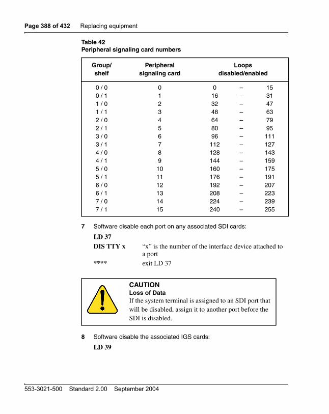
Page 388 of 432 Replacing equipment
553-3021-500 Standard 2.00 September 2004
7 Software disable each port on any associated SDI cards:
8 Software disable the associated IGS cards:
Table 42Peripheral signaling card numbers
Group/shelf
Peripheralsignaling card
Loopsdisabled/enabled
0 / 00 / 11 / 01 / 12 / 02 / 13 / 03 / 14 / 04 / 15 / 0 5 / 16 / 06 / 17 / 07 / 1
0123456789101112131415
0163248648096
112128144160176192208224240
––––––––––––––––
153147637995
111127143159175191207223239255
LD 37DIS TTY x “x” is the number of the interface device attached to
a port
**** exit LD 37
CAUTIONLoss of DataIf the system terminal is assigned to an SDI port that will be disabled, assign it to another port before the SDI is disabled.
LD 39

Replacing equipment Page 389 of 432
Communication Server 1000M and Meridian 1 Large System Maintenance
You will see ISR043 on the system terminal when the card is disabled. Busy channels will not be disabled until the call is disconnected.
9 Set the ENB/DIS switch on the 3PE to DIS.
10 Tag and disconnect cables to the 3PE.
11 Unhook the locking devices on the card; pull it out of the card cage.
Installing equipment
1 Set the ENB/DIS switch to DIS on the replacement 3PE card.
2 Set option switches on the replacement card the same as on the card you removed. If there is a vintage change, be sure to check Circuit Card: Description and Installation (553-3001-211) for any differences.
3 Insert the replacement card into the vacated slot and hook the locking devices.
4 Connect cables to the replacement card.
5 Set the ENB/DIS switch to ENB on the replacement card.
6 Enable cards.
Enable and test the CNI and 3PE cards:
If the LED on the 3PE card turns off, go to step 7 on page 389. If the LED stays lit, press the Man Int button to initialize the system.
If the 3PE card is in the Core/Network, enable the clock controller card:
If there is a problem, a CED or CCED system message is generated and the red LED lights on the faceplate of the appropriate card.
7 Check to see that all cards were enabled.
DISI IGS x “x” is the IGS card number—0 to 19
**** exit LD 39
LD 135ENL CNI c s p CPU (0 or 1). Slot 12, port 0.
**** exit LD 135
LD 60ENL CC x**** exit LD 60
Page 390 of 432 Replacing equipment
553-3021-500 Standard 2.00 September 2004
8 Check the status of the IGS card:
9 If the card is still disabled, enable it:
10 Check the status of SDI ports:
LD 37STAT
11 If any port still disabled, enable it:
12 Check the status of the peripheral signaling card:
13 If the card is still disabled, enable it:
14 Tag defective equipment with a description of the problem and package it for return to a repair center.
QPC471, QPC775 Clock Controller CardUse this procedure to replace a clock controller (CC) card.
Note: The QPC775 Clock Controller is used in Canadian and International applications. QPC775 and QPC471 cards cannot be combined in one system.
LD 39STAT IGS x “x” is the IGS card number—0 to 19
ENL IGS xx**** exit LD 39
ENL TTY x**** exit LD 37
LD 32STAT PER x Table 42 on page 388 lists peripheral signaling card
numbers
ENPS x**** exit LD 32
Replacing equipment Page 391 of 432
Communication Server 1000M and Meridian 1 Large System Maintenance
See ISDN Basic Rate Interface: Maintenance (553-3001-518) for a description of all maintenance commands, and Software Input/Output: System Messages (553-3001-411) for interpreting system messages.
Removing equipment
1 The clock controller card must be on the inactive CPU. If you need to switch the active CPU:
LD 135SCPU****
2 Disable the clock controller card:
— The card you are removing must be inactive:
LD 60
— In a single-CPU system:
— In a dual-CPU system:
DANGERModule covers are not hinged; do not let go of the cover. Lift the cover away from the module and set it out of your work area.
Disable the clock controller card.
DIS CC x “x” is the card number—0 or 1
Check the status of the clock controller card you are removing.
SSCK x “x” is the card number—0 or 1
If the clock is active, switch clocks.
SWCK switch system clock from active to standby
Make sure the card you are removing is disabled and the other clock controller card is active and in free run mode.
SSCK xTRCK FRUNDisable the clock controller card you are removing.
DIS CC x “x” is the card number—0 or 1

Page 392 of 432 Replacing equipment
553-3021-500 Standard 2.00 September 2004
3 Set the ENB/DIS switch to DIS on the card you are removing.
4 Tag and disconnect cables to the card you are removing.
5 Unhook the locking devices on the card; pull it out of the card cage.
Installing equipment
1 Set the ENB/DIS switch to DIS on the replacement card.
2 Set option switches on the replacement card. If there is a vintage change, be sure to check Circuit Card: Description and Installation (553-3001-211) for any differences.
3 Insert the replacement card into the vacated slot and hook the locking devices.
4 Connect cables to the replacement card.
5 Set the ENB/DIS switch to ENB on the replacement card.
6 Software enable the card:
ENL CC x
Note: With a vintage H clock controller card, do not issue the tracking (TRCK) or status (SSCK) commands at this time. If you do issue these commands, the system may respond with an inaccurate error condition.
— In a single-CPU system, complete the replacement procedure by exiting LD 60:
****
— In a dual-CPU system proceed with the following steps.
7 Switch CPUs:
LD 135SCPU****
CAUTIONService InterruptionTo avoid interrupting service, set ENB/DIS switches to DIS before disconnecting or connecting cables.

Replacing equipment Page 393 of 432
Communication Server 1000M and Meridian 1 Large System Maintenance
8 Activate the newly installed card and verify that it is active:
LD 60 SWCKSSCK x
9 If applicable, issue a tracking command:
Note: Set the clock source to the status it was in before the replacement procedure.
10 Verify clock switch-over and tracking:
11 Tag defective equipment with a description of the problem and package it for return to a repair center.
QPC477 Bus Terminating UnitUse this procedure to replace a bus terminating unit (BTU).
Note: Check the codes on all replacement BTUs.
TRCK aaa “aaa” is PCK for track primary clock, SCLK for track secondary clock, or FRUN for free run mode
SWCKSSCK x**** exit LD 60

Page 394 of 432 Replacing equipment
553-3021-500 Standard 2.00 September 2004
QPC477-A10 and QPC477-B10 BTUs are interchangeable in NT8D35 Network Modules.
1 Turn off power to the module:
— With AC power, set the circuit breaker on the Module Power Distribution Unit (MPDU) to OFF (down).
— With DC power, set the switch on the power supply to OFF (down).
2 Remove enough cards on both sides of the BTU to access the unit.
See Circuit Card: Description and Installation (553-3001-211) for BTU slot locations.
3 Gently pull the BTU out of the card cage.
4 Insert the replacement BTU into the vacated slot.
5 Reinstall the cards on both sides of the BTU.
6 Turn on power to the module:
— With AC power, set the MPDU circuit breaker to ON (up).
— With DC power, set the power supply switch to ON (up).
Note: As necessary, software reenable cards in the module. See the appropriate replacement procedures in this document.
7 Tag defective equipment with a description of the problem and package it for return to a repair center.
QPC659 Dual Loop Peripheral Buffer CardUse this procedure to replace a dual loop peripheral buffer (DLB) card.
DANGERModule covers are not hinged; do not let go of the cover. Lift the cover away from the module and set it out of your work area.

Replacing equipment Page 395 of 432
Communication Server 1000M and Meridian 1 Large System Maintenance
See Software Input/Output: Administration (553-3001-311) for a description of all maintenance commands, and Software Input/Output: System Messages (553-3001-411) for interpreting system messages.
Removing equipment
1 Software disable the dual loop peripheral buffer:
2 Set the ENB/DIS switch to DIS.
3 Tag and disconnect cables to the card you are removing.
4 Unhook the locking devices on the card; pull it out of the card cage.
Installing equipment
1 Set the ENB/DIS switch to DIS on the replacement card.
2 Set option switches on the replacement card the same as on the card you removed. If there is a vintage change, be sure to check Circuit Card: Description and Installation (553-3001-211) for any differences.
3 Insert the replacement card into the vacated slot and hook the locking devices.
4 Connect cables to the replacement card.
5 Set the ENB/DIS switch to ENB on the replacement card.
DANGERModule covers are not hinged; do not let go of the cover. Lift the cover away from the module and set it out of your work area.
CAUTIONService InterruptionService is interrupted when a loop is disabled.
LD 32DISS l s “l s” are the loop and shelf numbers

Page 396 of 432 Replacing equipment
553-3021-500 Standard 2.00 September 2004
6 Software enable the replacement card by enabling the shelf:
ENLS l s
— When the process is complete, you will receive a system response.
— If there is no problem, exit LD 32:
****
7 Test each shelf:
LD 30SHLF l s
— If there is a problem, an NWS system message is generated and the appropriate red LED lights on the faceplate of the card.
— If there is no problem, exit LD 30:
****
8 Tag defective equipment with a description of the problem and package it for return to a repair center.
QPC841 Serial Data Interface CardUse this procedure to replace a serial data interface (SDI) card.
See Software Input/Output: Administration (553-3001-311) for a description of all maintenance commands, and the Software Input/Output: System Messages (553-3001-411) for interpreting system messages.
DANGERModule covers are not hinged; do not let go of the cover. Lift the cover away from the module and set it out of your work area.

Replacing equipment Page 397 of 432
Communication Server 1000M and Meridian 1 Large System Maintenance
Removing equipment
1 Software disable each port on the SDI:
2 Set the ENB/DIS switch to DIS.
3 Tag and disconnect cables to the card you are removing.
4 Unhook the locking devices on the card; pull it out of the card cage.
Installing equipment
1 Set the ENB/DIS switch to DIS on the replacement card.
2 Set option switches on the replacement card the same as on the card you removed. If there is a vintage change, be sure to check Circuit Card: Description and Installation (553-3001-211) for any differences.
3 Insert the replacement card into the vacated slot and hook the locking devices.
4 Connect cables to the replacement card.
5 Set the ENB/DIS switch to ENB on the replacement card.
CAUTIONLoss of DataIf the system terminal is assigned to the SDI being replaced, assign it to another port before this SDI is disabled.
LD 37DIS TTY x “x” is the number of the interface device attached to
a port
CAUTIONService InterruptionTo avoid interrupting service, set ENB/DIS switches to DIS before disconnecting or connecting cables.

Page 398 of 432 Replacing equipment
553-3021-500 Standard 2.00 September 2004
6 Software enable each port on the card:
ENL TTY x
— When the process is complete, you will receive a system response.
— If there is a problem, an IOD system message is generated and the red LED lights on the faceplate of the card.
— If there is no problem, exit LD 37:
****
7 Tag defective equipment with a description of the problem and package it for return to a repair center.
Replacing an NT7D10 PDU with an NT7D67CB PDUUse this procedure to replace an NT7D10 PDU with an NT7D67CB PDU in DC-powered systems.
Note 1: The NT7D67CB PDU replaces the NT7D10 PDU. However, both PDUs can be used in a system.
Note 2: Conduit is not required with the NT7D67CB PDU but can be used.
Before you begin this procedure, prepare for the installation:
• Additional wire may be required (see step 1 on page 399).
• An electric drill, fitted with a .234-in. metal bit must be available.
• A Rear Mount Conduit Kit (NT7D0902) must be available
DANGERModule covers are not hinged; do not let go of the cover. Lift the cover away from the module and set it out of your work area.

Replacing equipment Page 399 of 432
Communication Server 1000M and Meridian 1 Large System Maintenance
Removing equipment
1 Check the length of existing wire to the PDU. Due to the location of the field wiring terminal block on the NT7D67CB PDU, 6 to 9 inches more length is required to reach its terminals than is required to reach those on the NT7D10 PDU.
Note 1: The existing service loop where wire enters the pedestal may have enough excess length or enough slack wire may exist in the conduit path from the power plant to allow pulling a sufficient amount through to the pedestal. Figure 61, located further on in this procedure, shows the location on the NT7D67CB PDU to which wiring must extend. If existing wiring will not reach, replace the entire wire run from the power plant. Do not splice short pieces of wire onto the end of existing wiring.
Note 2: If a QCAD321 or an NT6D53 junction box is installed on the power feed to the console, the wiring from the power plant may have to be altered as follows:
• If five #4 AWG wires are run from the power plant to the junction box (two BAT, two RTN, and one LRTN), then the junction box must not be used. The junction box must be removed and the entire wire run from the power plant to the pedestal must be replaced. Do not splice short pieces of wire onto the end of existing wiring.
• If nine #4 AWG wires are run from the power plant to the junction box (four BAT, four RTN, and one LRTN), then the junction box can be used. However, the #10 AWG wires from the junction box to the pedestal may have to be replaced to provide sufficient length. Do not splice short pieces of wire onto the end of existing wiring.
2 Disconnect DC power at the source (not at the PDU).
3 Remove the grill on the rear of the pedestal.
4 Set all five circuit breakers on the PDU to OFF (down). Figure 58 shows the NT7D10 PDU in the rear of the pedestal.
5 Unseat the blower unit in the front of the pedestal:
DANGERBefore performing these procedures, disconnect the power at the source; simply turning off the circuit breakers does not shut off power to the system monitor.

Page 400 of 432 Replacing equipment
553-3021-500 Standard 2.00 September 2004
a. Remove the grill on the front of the pedestal. Set the toggle switch on the front of the unit to OFF (left).
b. Turn the screws on the front of the unit counterclockwise and pull the unit out several inches so the connector on the rear disengages.
6 Disconnect cables to the module above the pedestal (module 0):
a. Remove the rear cover on the module.
b. Remove the I/O safety panel over the backplane in the module.
Figure 58NT7D10 Power Distribution Unit DC
DANGERThe unit is heavy and the blades on the blower may still be rotating up to two minutes after the power is turned off.
Circuit breaker bank553-3039
System monitor
Field wiring terminal(below PDU)
PDU
Ground lugs

Replacing equipment Page 401 of 432
Communication Server 1000M and Meridian 1 Large System Maintenance
c. Disconnect the system monitor ribbon cable from the PDU and from the module and set it aside for reconnection with the replacement NT7D67CB PDU.
d. Disconnect the large orange power connector (J1) from the PDU.
Note: To disconnect the power plug, you must press a latch trip on the front and rear of the plug. You may need to use a screwdriver blade against the latch trip on the front of the plug.
7 Tag and disconnect cables to the NT8D22 System Monitor card. Loosen the two screws on the card faceplate and remove it.
8 Remove the six screws that position the NT7D10 PDU. Carefully pull the unit straight out and set it on the floor next to the pedestal (see Figure 59)
9 Tag and then disconnect all wiring to the field wiring terminal block.
10 Locate the frame ground wire from the field wiring terminal block to the frame ground bolt inside the pedestal. Disconnect this wire at the ground bolt.
11 Remove the field wiring terminal block:
a. Remove the cover over the terminal block.
b. Remove the four screws that secure the terminal block and lift it out of the pedestal.
12 Move the NT7D10 PDU out of the work area.
CAUTIONDamage to EquipmentThe PDU cannot be completely removed from the pedestal until wires to the field wiring terminal block are disconnected. Label wires carefully. Improper wiring can cause system damage.

Page 402 of 432 Replacing equipment
553-3021-500 Standard 2.00 September 2004
Installing equipment
Note: The conduit attachment plate provided in the NT7D0902 Rear Mount Conduit Kit must be installed as a safety cover and to restrain wiring to the terminal block.
1 Drill two .234-in. screw holes in the rear of the pedestal (see Figure 59). The holes will be used to install the conduit attachment plate.
2 Place the NT7D67CB PDU next to the pedestal.
Figure 60 shows the PDU (labeled FLTR/PWR DIST UNIT ASSY on the equipment) and the NT7D10CA System Monitor/Power Supply Assembly (labeled XSM/PWR SUPPLY ASSY on the equipment).
Note: The NT7D09CA Pedestal has a brace that supports a leveling bracket on the rear of the PDU. There is no room for the leveling bracket in the NT7D09AA Pedestal, so the bracket must be removed before the PDU is installed.
DANGERThe NT7D67CB PDU is much heavier than the NT7D10 PDU.
Figure 59Dimensions for drilling holes on the pedestal
553-5489
Drill .234 in.diameter through
(two places)
9.13 in.
1.0 in.
.75 in.

Replacing equipment Page 403 of 432
Communication Server 1000M and Meridian 1 Large System Maintenance
3 Remove the two screws that secure the leveling bracket on the rear of the PDU. Reinstall the screws to hold the rear cover on the PDU in place.
4 Install the NT7D67CB PDU:
Figure 60NT7D67CB Power Distribution Unit DC
DANGERYou should support the PDU as far into the pedestal as you can without letting it drop to the bottom of the pedestal, but watch your hands! It becomes more difficult to support the PDU the further into the pedestal it is inserted. The PDU is held in its proper position only when the mounting screws on its faceplate are tightened.
553-5488Filter / Power distribution unit assembly
Circuit breakers
NT7D67CB
Circuit breakers
FLTR / PWR DISTUNIT ASSY
System monitor/power supply assembly
BLO CB0
CB1
CB2
CB3
Safety cover—thefield terminal blockis behind the cover
J5J3 J6 J4
NT7D10CA

Page 404 of 432 Replacing equipment
553-3021-500 Standard 2.00 September 2004
a. Connect the green frame ground wire from the PDU to the frame ground bolt inside the pedestal.
b. Guide the power cable connector through the hole in the top of the pedestal. Set the PDU in the pedestal and tighten the three screws that secure it to the pedestal.
5 Install the NT7D10CA system monitor assembly:
a. Connect the small orange connectors (J2 on the PDU, P2 on the system monitor assembly) on the left side of the PDU.
b. Connect the flat white connector to the small circuit board (P1 on the PDU, J1 on the system monitor assembly) on the right side of the PDU.
c. Connect the ribbon cable (set aside when the NT7D10 PDU was removed) to the system monitor (J2). Guide the connector on the other end of the cable through the hole in the top of the pedestal and connect it to module 0.
d. Gently push the system monitor assembly into the pedestal.
6 Tighten the screws that secure the system monitor assembly.
7 Reconnect the cables from module 0:
a. Reconnect the large orange power connector (J1).
b. Replace the I/O safety panel.
c. Replace the rear cover on the module.
8 Reconnect all external wiring to the terminal block on the PDU (see Figure 61):
a. Remove the plastic safety cover over the terminal block.
b. Connect the red BAT (–48 V) wires:
— for modules 0 and 1 connect to the BAT 0,1 terminal
— for modules 2 and 3 connect to the BAT 2,3 terminal
c. Connect the black BATRTN (48 V return) wires:

Replacing equipment Page 405 of 432
Communication Server 1000M and Meridian 1 Large System Maintenance
— for modules 0 and 1 connect to the BATRTN 0,1 terminal
— for modules 2 and 3 connect to the BATRTN 2,3 terminal
d. Connect the orange (or white) wire from the ground bus/LRE in the power plant to the LRTN terminal.
9 Position the conduit attachment plate on the rear of the pedestal (over the newly drilled holes) and secure it with two screws, nuts, and washers.
10 Reinstall the plastic safety cover over the terminal block.
11 Reseat the blower unit:
a. Lift the unit slightly and slide it into the pedestal glides. Set the toggle switch to ON (right).
b. Tighten the screws on the front of the unit.
c. Replace the front pedestal grill.
12 Insert the system monitor card. Tighten the screws on the card faceplate. Reconnect cables to the system monitor.
13 Set all five circuit breakers on the PDU to OFF (down). Reconnect the source of DC power.
Figure 61Field wiring terminals in the NT7D67CB PDU
553-5800
NT7D67CB FLTR / PWR DISTUNIT ASSY
BAT0,1
BAT2,3 LRTN
BATRTN0,1
BATRTN2,3
BLO CB0 CB1 CB2 CB3
Page 406 of 432 Replacing equipment
553-3021-500 Standard 2.00 September 2004
14 One at a time, starting with the breaker for the blower unit, set the circuit breakers on the PDU to ON (up). Make sure the green LED lights on the power supply unit(s) in each module.
Note: On initial power up the blower may rotate slower than expected. As the sensor detects heat, the blower will rotate more rapidly.
15 Replace the rear pedestal grill.
16 Tag defective equipment with a description of the problem and package it for return to a repair center.

Page 407 of 432
Communication Server 1000M and Meridian 1 Large System Maintenance
414
Technical Assistance service
ContentsThis section contains information on the following topics:
Nortel Networks Technical Assistance Centers . . . . . . . . . . . . . . . . . . 407
Services available . . . . . . . . . . . . . . . . . . . . . . . . . . . . . . . . . . . . . . . . . 410
Requesting assistance . . . . . . . . . . . . . . . . . . . . . . . . . . . . . . . . . . . . . . 413
Nortel Networks Technical Assistance CentersTo help customers obtain maximum benefit, reliability, and satisfaction from their CS 1000E systems, Nortel Networks provides technical assistance in resolving system problems. Table 43 lists the centers that provide this service.
Table 43Customer Technical Services (Part 1 of 3)
Location Contact
Nortel Networks Global Networks Technical Support (GNTS) PO Box 833858 2370 Performance Drive Richardson, TX 75083 USA
North America
Telephone: 1 800 4NORTEL

Page 408 of 432 Technical Assistance service
553-3021-500 Standard 2.00 September 2004
Nortel Networks Corp.P.O. Box 4000250 Sydney StreetBelleville, OntarioK8N 5B7 Canada
North America
Telephone: 1 800 4NORTEL
Nortel Service Center - EMEA EMEA
Telephone: 00 800 8008 9009 or+44 (0)870 907 9009
E-mail: [email protected]
Nortel Networks1500 Concord TerraceSunrise, Florida 33323USA
BrazilTelephone: 5519 3705 7600E-mail: [email protected]
English Caribbean Telephone: 1 800 4NORTEL
Spanish Caribbean Telephone: 1 954 858 7777
Latin AmericaTelephone: 5255 5480 2170
Table 43Customer Technical Services (Part 2 of 3)
Location Contact

Technical Assistance service Page 409 of 432
Communication Server 1000M and Meridian 1 Large System Maintenance
Network Technical Support (NTS) Asia PacificTelephone: +61 28 870 8800
Australia Telephone:1800NORTEL (1800 667835) or +61 2 8870 8800E-mail: [email protected]
People’s Republic of ChinaTelephone: 800 810 5000E-mail: [email protected]
JapanTelephone: 010 6510 7770E-mail: [email protected]
Hong Kong Telephone: 800 96 4199E-mail: [email protected]
TaiwanTelephone: 0800 810 500E-mail: [email protected]
IndonesiaTelephone: 0018 036 1004
MalaysiaTelephone: 1 800 805 380
New ZealandTelephone: 0 800 449 716
Philippines Telephone: 1 800 1611 0063 or 632 917 4420
SingaporeTelephone: 800 616 2004
South KoreaTelephone: 0079 8611 2001
Thailand:Telephone: 001 800 611 3007
Table 43Customer Technical Services (Part 3 of 3)
Location Contact
Page 410 of 432 Technical Assistance service
553-3021-500 Standard 2.00 September 2004
Services availableServices available through the Technical Assistance Centers include:
• diagnosing and resolving software problems not covered by support documentation
• diagnosing and resolving hardware problems not covered by support documentation
• assisting in diagnosing and resolving problems caused by local conditions
There are several classes of service available. Emergency requests (Class E1 and E2) receive an immediate response. Service for emergency requests is continuous until normal system operation is restored. Non-emergency

Technical Assistance service Page 411 of 432
Communication Server 1000M and Meridian 1 Large System Maintenance
requests (Class S1, S2, and NS) are serviced during normal working hours. Tables 44 and 45 describe the service classifications.
Table 44Technical service emergency classifications
Class Degree of failure Symptoms
E1 Major failure causing system degradation or outage
System out-of-service with complete loss of call-processing capability.
Loss of total attendant console capability.
Loss of incoming or outgoing call capability.
Loss of auxiliary Call Detail Reporting (CDR) in resale application.
Call processing degraded for reasons such as trunk group out-of-service:
• 10% or more lines out-of-service
• frequent initializations (seven per day or more)
• inability to recover from initialization or SYSLOAD
• consistently slow dial tone (eight seconds or more delay)
E2 Major failure causing potential system degradation or outage
Standby CPU out-of-service.
Frequent initializations (one per day or more).
Disk drive failure.
Two sets of disks inoperative.

Page 412 of 432 Technical Assistance service
553-3021-500 Standard 2.00 September 2004
Except as excluded by the provisions of warranty or other agreements with Nortel Networks, a fee for technical assistance may be charged, at rates established by Nortel Networks. Information on rates and conditions for services are available through Nortel Networks sales representatives.
Table 45Technical services non-emergency classifications
Class Degree of failure Symptoms
S1 Failure that affects service Software or hardware trouble directly and continuously affecting user's service or customer's ability to collect revenue.
Problem that will seriously affect service at in-service or cut-over date.
S2 Intermittent failure that affects service
Software or hardware faults that only intermittently affect service.
System-related documentation errors that directly result in or lead to impaired service.
NS Failure that does not affect service
Documentation errors.
Software inconsistencies that do not affect service.
Hardware diagnostic failures (not defined above) that cannot be corrected by resident skills.
Test equipment failures for which a backup or manual alternative can be used.
Any questions concerning products.

Technical Assistance service Page 413 of 432
Communication Server 1000M and Meridian 1 Large System Maintenance
Requesting assistanceCollect the information listed in Table 46 before you call for service.
Table 46Checklist for service requests
Name of person requesting service
Company represented
Telephone number
System number/identification
Installed software generic and issue (located on data disk)
Modem telephone number and password (if applicable)
Seriousness of request(see Tables 44 and 45)
Description of assistance required

Page 414 of 432 Technical Assistance service
553-3021-500 Standard 2.00 September 2004

Page 415 of 432
Communication Server 1000M and Meridian 1 Large System Maintenance
418
List of terms3PE card
QPC441 Three-Port Extender Card
BTU QPC477 Bus Terminating Unit
CBT Core Bus Terminator
CE Common Equipment
CE/PE Common/Peripheral Equipment
CMA cardChangeover and Memory Arbitrator Card
CMDU cardCore Multi Disk Unit Card
Conference/TDS cardNT8D17 Conference/Tone and Digit Switch Card
CNI Core to Network Interface
CP Call Processor
CPU Central Processing Unit

Page 416 of 432 List of terms
553-3021-500 Standard 2.00 September 2004
DLB card QPC659 Dual Loop Peripheral Buffer Card
DTR card Digitone Receiver Card
Network/DTR cardNT8D18 Network/Digitone Receiver Card
FDI cardQPC742 Floppy Disk Interface Card
FDU NT8D68 Floppy Disk Unit
FN card QPC579 CPU Function Card
IF card QPC580 CPU Interface Card
IOP Input/Output Processor
IPE Intelligent Peripheral Equipment
MDU NT8D69 Multi Disk Unit
MSI cardQPC742 Mass Storage Interface Card
IPE Intelligent Peripheral Equipment
PS card QPC43 Peripheral Signaling Card
ROM cards Read Only Memory Cards
SBE QPC215 Segmented Bus Extender Card

List of terms Page 417 of 432
Communication Server 1000M and Meridian 1 Large System Maintenance
SDI cardsSerial Data Interface Cards
UPSUninterruptible Power Supply

Page 418 of 432 List of terms
553-3021-500 Standard 2.00 September 2004

Page 419 of 432
Communication Server 1000M and Meridian 1 Large System Maintenance
Index
Numerics3PE (Three-Port Extender) Cards
in Core Module Card Cage replacement, 298installing, 389removing, 385
3PE (three-port extender) cards, 62
500/2500 telephonesmajor alarms and, 227PFTU connection to CO trunks, 232
AA0321130 Fan Units
removing, 243
A0378252 Battery Pack Assemblyremoving, 243
access, local/remotedescribed, 19to system terminals, 20
accessing systemCPU (central processing unit), 17from maintenance telephones, 24
acronym definitions, 415
add-on module problems, 143
Air Filtersinstalling, 381removing, 381
air filters, pedestalblocked, 235servicing, 237
air probe, 37
Air Probe Harnessesinstalling, 347removing, 345
alarm displays, 31
alarms, system, 227
Analog Line Cardsinstalling, 329removing, 328
Analog Message Waiting Line Cardsinstalling, 329removing, 328
antistatic bags, 210
antistatic wrist straps, 210
attendant console alarm indications, 227, 228
attendant console faultscallout/callin problems, 123, 125equipment overview, 121indicator or digit display problems, 127list of symptoms, 121operator cannot hear or be heard, 128typical system messages for, 31, 122typical user-reported problems for, 35, 123typical visual fault indicators for, 32, 123
BBackground Routines
described, 198programs used in, 199

Page 420 of 432 Index
553-3021-500 Standard 2.00 September 2004
backplanesjumpers, 296
Battery Pack Assemblyremoving, 243
battery pack assembly, option 21Eroutine maintenance, 237
battery systems, DC-power, 238
BKGD prompt, 199
blower unit problems, 48, 57
Blower Unitsin PDU replacement, 313, 317, 318, 322, 399,
405installing, 350removing, 348
blower units, 37
BTU (Bus Terminating Unit)removing and installing, 393
BTU (bus terminating unit), 61
BUG messages, 198
Ccables
connecting, 214in PDU replacement, 314, 317, 318, 321, 400,
404removing, 213
call processingInitialize Program effect on, 198sysload effect on, 225system initialization effect on, 223
call processor (CP) card, 270, 368
callscaller cannot hear or be heard, 135callout/callin problems, 115, 117, 123, 125,
133, 135conferencing problems, 94no-ring problems (500 or 2500 models), 145placement problems (2500 telephones and
some trunks), 96transfer problems, 94, 141volume or noise problems, 139
captive screws, 241
Card CagesIPE Module, 365
cards, circuitenable/disable switch, 217excessive error messages from, 200LEDs, 217maintenance displays, 221maintenance features, 216
cards, reseating/reenabling, 28
CBT (Core Bus Terminator) Cardsremoving and installing, 310
CC (Clock Controller) Cardsin 3PE Card replacement, 386, 387in Core Module Card Cage replacement, 292,
298, 301installing, 392removing, 391
CCED system messages3PE Card replacement, 389CNI Card replacement, 313CP Card replacement, 275, 278, 372
CED system messages3PE Card replacement, 389
Central Office Trunk Cardsremoving, 327, 328
CE Power Supply AC, 332
CE Power Supply DC, 309
changeover card reload button location, 226
circuit breaker off, 42, 48, 52

Index Page 421 of 432
Communication Server 1000M and Meridian 1 Large System Maintenance
circuit breakersIPE Module Card Cage replacement, 365, 367MPDU replacement, 354, 355PDU replacement, 318, 323Power Supply AC replacement, 332
Circuit cards, handling, 210
clock controller (CC) card, 390
CMDU (Core Multi Disk Unit), 61
CMDU (Core Multi Drive Unit)in CP Card replacement, 276removing, 310
CNF system messages, 335
CNI (Core Network Interface) cards, 62
CNI (Core to Network Interface) Cards, 310in 3PE Card replacement, 385, 386, 389in Core Module Card Cage replacement, 298,
299installing, 312removing, 312
CNI-3 card, 311
columns, configuring PFTUs with, 232
commandsentering on maintenance telephones, 25LMAX, 201
common equipment faultsequipment overview, 61floppy disk problem, 68list of symptoms, 61maintenance display codes/locations for, 33,
63procedures for clearing, 62typical fault indicators, 62typical system messages for, 30, 62typical user-reported problems for, 34, 63typical visual fault indicators for, 32
communicating with system, 17
conference call problems, 94
Conference/TDS Cardsinstalling, 334removing, 334
Conference/TDS cardsinstalling, 334removing, 334
configurations, equipmentcolumns with PFTUs, 232, 233remote maintenance monitoring, 21
CONF/TDS (conference/tone and digit switch) cards, 73
continuity testsfor peripheral equipment fault clearance, 100for trunk fault clearance, 115
continuity tests, manualdescribed, 204loopback configurations, 207point-to-point configurations, 206
controller card problems, 102, 104
Controller Cardsinstalling, 326removing, 325, 326
cooling system temperature alarms, 235
Core card cage, 291
Core Module Card Cagesinstalling, 296
Core Modules, option 61C/81, 203
Core/Network Card Cagesinstalling, 296
Core/Network Module backplanesdisconnecting cables from, 213
core to network interface (CNI) card, 311
CP (call processor), 61
CP (Call Processor) card ports, 21
CP (Call Processor) Cardsin Core Module Card Cage replacement, 292,
299installing, 271, 276, 369removing, 271, 368
CPIO ports, 21
Page 422 of 432 Index
553-3021-500 Standard 2.00 September 2004
CPU (central processing unit), 61accessing, 17downloading firmware from, 198line transfer on failure of, 232
CPU controls, 223
CTS, contacting, 407
Ddata cartridges, 61
data disks, precautions, 212
DCE ports, 21
DC-power battery systems, 238
definitions of terms and acronyms, 415
diagnostics, interactive, 204
diagnostic software programs, 197
dial pad, terminal keyboard translation to, 25
Digital Line Cardsinstalling, 329removing, 328
Direct Dial Inward Trunk Cardsremoving, 328
Direct Inward Dial Trunk Cardsremoving, 327, 328
Direct Outward Dial Trunk Cardsremoving, 328
disabling circuit cards, 217
disks, precautions, 212
DLB (Dual Loop Peripheral Buffer) Cardsinstalling, 395removing, 395
downloading firmware, 198
DROL prompt, 199
DTE ports, 21
DTI (Digital Trunk Interface), 292
DTR (Digitone Receiver) Cardsinstalling, 329removing, 328
dual CPU systems, 223
dual loop peripheral buffer card problems, 106
Dual Port SDI Paddle Boardsinstalling, 339removing, 338
EE&M Trunk Cards
installing, 329removing, 328
E&M trunk cards, 113
EMI shield, 296
enable/disable switchesdescribed, 217location, 218
enabling circuit cards, 217
equipment replacement, 28
ERR messages, 198
ERR mnemonic, 198
ERRM prompt, 198
Error Monitor program, 198
Extraction Tool, 213
FFan Units
removing, 243
fault clearingbasics, 27final maintenance procedure, 193order for clearing multiple, 28
faultsmaintenance display indications, 221major alarms, 227minor alarms, 228NT8D22 System Monitor, 229, 230trunk, 201
fibre peripheral controller card problems, 100

Index Page 423 of 432
Communication Server 1000M and Meridian 1 Large System Maintenance
field wiring terminal blocks, 315, 316, 320, 322, 352, 353, 401, 405
final maintenance procedure, 193
firmware, 198
Flexible Analog Line Cardsremoving, 327
floppy disk problem, 68
floppy disks, 61
Gglossary, 415
grills, removing, 241
Hhandsfree unit problems, 141
hardware maintenance tools, 215
History File, 33described, 203maintenance display codes, 219
HWI0533 messages in CP Card replacement, 275, 278, 372
IIGM (InterGroup Module), 299
IGS (InterGroup Switch) Cardsin 3PE Card replacement, 386, 388, 390
IGS (intergroup switch) cards, 73
INI messages, 299
initialize buttondescribed, 223Initialize Program and, 198
Initialize Program, 198
installingConference/TDS cards, 334NT5D12AA Dual DTI/PRI Card, 280NT5K09 Quad Digitone Receiver, 303, 374NT5K10 Dual Loop Peripheral Buffer Card
(IDLB), 304NT5K1106 Enhanced Peripheral Equipment
Card Cage, 307
intelligent peripheral card self-test, 216
intelligent peripheral equipment (IPE) cards, 327
interactive diagnostics, 204
IOD system messagesSDI Paddle Board replacement, 339SDI replacement, 398
IOP (I/O Processor) Cardsremoving, 310
I/O processor (IOP/CMDU) cardremoving, 281
IPE (Intelligent Peripheral Equipment) Cardsinstalling, 329removing, 327
IPE Module Card Cagesinstalling, 366removing, 365
Jjumpers
in IPE Card replacement, 329
junction box in PDU replacement, 399
Kkeyboard to dial pad translation, 25
LLD 11 (Multi-Line Telephone Administration), 24
LD 17 (Short Memory Test), 202
LD 17 programCNI Card replacement, 311for passwords, 18

Page 424 of 432 Index
553-3021-500 Standard 2.00 September 2004
LD 21 program, 26
LD 22 (Print Routine 3), 203
LD 30 (Network and Signaling Diagnostic), 219
LD 30, for reviewing and resetting maintenance display codes, 33
LD 30 programDLB replacement, 396IPE Module Card Cage replacement, 367Peripheral Signaling Card replacement, 384
LD 32 program3PE Card replacement, 390Controller Card replacement, 326DLB replacement, 395in 3PE Card replacement, 387IPE Card replacement, 329IPE Module Card Cage replacement, 365Network Card replacement, 331Peripheral Signaling Card replacement, 383
LD 34 programConference/TDS Card replacement, 334, 335
LD 35, for clearing fault indicators, 194
LD 36 Trunk Diagnostic, 201
LD 37 program3PE Card replacement, 388, 390Core Module Card Cage replacement, 293, 302SDI Paddle Board replacement, 338SDI replacement, 397System Monitor replacement, 337
LD 38 programConference/TDS Card replacement, 334, 335
LD 39 program3PE Card replacement, 388, 390
LD 43 programCNI Card replacement, 311
LD 44 (Software Audit), 199
LD 45 (Background Signaling and Switching Diagnostic), 205
LD 46 programConference/TDS Card replacement, 334, 335
LD 60 program3PE Card replacement, 389CC replacement, 391, 393Core Module Card Cage replacement, 293, 301in 3PE Card replacement, 387
LD 135 (Core Common Equipment Diagnostic), 24, 219
LD 135, for clearing fault indicators (system options 51C, 61C and 81), 194
LD 135 programSecurity Device replacement, 2903PE Card replacement, 387, 389CC replacement, 391, 392CNI Card replacement, 311, 312Core Module Card Cage replacement, 292,
299, 300CP Card replacement, 271, 275, 369
LD 137 (Core Input/Output Diagnostic), 24
LD 137 programCore Module Card Cage replacement, 300IODU/C Card replacement, 288
LDnnfor isolating attendant console faults, 121for isolating telephone faults, 131
LED (light emitting diode)described, 217indications, 219location, 220module power supply failures, 234temperature alarms, 235
LED on controller cards, 102, 104
LED on fibre peripheral controller cards, 100
LEDs, 31all off, 42, 45, 48, 51defective, 141green off on module power supply, 45, 54
LEDs in Thermostat Harness replacement, 340, 343
Line Cardsinstalling, 329removing, 327, 328

Index Page 425 of 432
Communication Server 1000M and Meridian 1 Large System Maintenance
Line Side T1removing, 327
line transfermajor alarms causing, 227situations causing, 232sysloads and, 202, 225system monitor and, 229
LMAX command, 201
loading software programsOverlay Loader, 200
Local Carrier Interface cardremoving/replacing, 323
locking latches, 241
login procedures, 18
loopback testsconfigurations, 207described, 205
Mmaintenance
routine, 237
maintenance display codescircuit cards/faults indicated, 221described, 219display location, 222for common equipment faults, 33, 63for peripheral equipment faults, 33
maintenance mode, 26
maintenance routines, interactive, 204
maintenance telephonesdescribed, 24loading overlay programs, 204translation from keyboard to dial pad, 25
major alarmsdefined, 227faults causing, 227
manual continuity testsdescribed, 204loopback configurations, 207point-to-point configurations, 206
mass storage interface cards, 61
mass storage units, 61
MDU (Multi Disk Unit), 61
memory arbitrator card reload button location, 226
Memory/Peripheral Signaling Cards, 335
memory shadowing, 312
MFS system messages, 335
Midnight Routinesdescribed, 198programs used in, 199
minor alarmsdefined, 227faults causing, 228
mnemonics, 23
modemsoption 61C/81
compatibility specifications, 22
guidelines, 21switch box/SDI/CPIO port connections, 22
module power distribution unit (MPDU), 37
module power supply, 38
MPDU (Module Power Distribution Unit)in Power Supply AC replacement, 332installing, 354removing, 354
MPDU (module power distribution unit), 37
MTA (maintenance set allowed) COS, 24
Multi User Login feature, 17
Music-on-Hold problems, 94
Nnetwork card cage, 355
Page 426 of 432 Index
553-3021-500 Standard 2.00 September 2004
Network Cardsinstalling, 331removing, 330, 331
network cards, 73
network equipment faultscall placement problems, 96call placement problems (2500 telephones and
some trunks), 96call transfer problems, 94conference call problems, 94list of symptoms, 73loops disabled, 75, 78, 82, 84, 86, 89Music-on-Hold problems, 94OVD messages for disabled loops, 75, 78, 82,
86, 92peripheral signaling card problems, 92, 93procedures for clearing, 74typical system messages for, 30, 75typical user-reported problems for, 34, 75typical visual fault indicators for, 32, 75
noise problems, 113, 139
no-ring problems (500 or 2500 models), 145
normal/maintenance switchesdescribed, 223
NPR system messagesController Card replacement, 327IPE Card replacement, 330Peripheral Signaling Card replacement, 384
NT1P61 Fibre Superloop Network cardremoving/replacing, 243
NT1P61 Fibre Superloop Network Cards, 75
NT1P62 Fibre Peripheral Controller Card, 245
NT1P62 Fibre Peripheral Controller cardremoving/replacing, 245
NT5D12AA Dual DTI/PRI Cardsinstalling, 280removing, 279
NT5D20 I/O Processor Cardsremoving, 281
NT5K09 Quad Digitone Receiver, 243installing, 303, 374removing, 303, 373
NT5K10 Dual Loop Peripheral Buffer Card (IDLB), 303
installing, 304removing, 304
NT5K1106 Enhanced Peripheral Equipment Card Cage, 305, 308
installing, 307removing, 306, 308, 309
NT6D40 Power Supply DC, 281
NT6D41 Power Supply DC, 309
NT6D42 Power Supply DC, 309
NT6D43 Power Supply DC, 309
NT6D63 I/O Processor Cardsremoving, 310
NT6D64 Core Multi Drive Unitsremoving, 310
NT6D65 Core to Network Interface Cards, 310installing, 312removing, 312
NT6D6003 Core Bus Terminator Cards, 310
NT6D6008 Core Card Cagesinstalling, 296
NT6D66 Call Processor (CP) card ports, 21
NT7D10 Power Distribution Unit DCinstalling, 316removing, 313
NT7D14 Power Supply ACinstalling, 333removing, 318
NT7D67CB Power Distribution Unit DCinstalling, 321removing, 318replacing NT7D10 with, 398
NT7R51 Local Carrier Interface Card, 323
NT7R51 Local Carrier Interface Card), 78

Index Page 427 of 432
Communication Server 1000M and Meridian 1 Large System Maintenance
NT7R52 Remote Carrier Interface Card, 324
NT8D01 Controller Cardsinstalling, 326removing, 326
NT8D02 Intelligent Peripheral Equipment Cardsinstalling, 329removing, 327
NT8D03 Intelligent Peripheral Equipment Cardsinstalling, 329removing, 327
NT8D04 Superloop Network Cardsinstalling, 331removing, 331
NT8D06 Power Supply ACinstalling, 333removing, 332
NT8D09 Intelligent Peripheral Equipment Cardsinstalling, 329removing, 327
NT8D14 Intelligent Peripheral Equipment Cardsinstalling, 329removing, 327
NT8D15 Intelligent Peripheral Equipment Cardsinstalling, 329removing, 327
NT8D16 Intelligent Peripheral Equipment Cardsinstalling, 329removing, 327
NT8D17 Conference/TDS Cardsinstalling, 334removing, 334
NT8D19 Memory/Peripheral Signaling Cards, 335
NT8D21 Power Supply ACinstalling, 333removing, 332
NT8D22 System Monitorsinstalling, 337removing, 336
NT8D29 Power Supply ACinstalling, 333removing, 332
NT8D41 Dual Port Serial Data Interface Paddle Boards
installing, 339removing, 338
NT8D46AC Thermostat Harnessesinstalling, 343removing, 340
NT8D46AM Air Probe Harnessesinstalling, 347removing, 345
NT8D46DC Air Probe Harnessesinstalling, 347removing, 345
NT8D52AB Pedestal Blower Unitsinstalling, 350removing, 348
NT8D52DD Pedestal Blower Unitsinstalling, 350removing, 348
NT8D53AB Power Distribution Unit ACinstalling, 352removing, 350
NT8D56AA Module Power Distribution Unitsinstalling, 354removing, 354
NT8D56AC Module Power Distribution Unitsinstalling, 354removing, 354
NT8D57 Module Power Distribution Unitsinstalling, 354removing, 354
NT8D04 Superloop Network Cards, 73, 82, 84
Page 428 of 432 Index
553-3021-500 Standard 2.00 September 2004
NT8D22 System Monitordescribed, 229message flow, 231module power supply failures, 234power unit designations from master, 236temperature alarms, 235
NT8D3703 IPE Module Card Cagesinstalling, 366removing, 365
NT9D19 Call Processor Cardsinstalling, 271, 276, 369removing, 271, 368
NT9D1102 Core/Network Card Cagesinstalling, 296
NT9P61 Fibre Superloop Network Card, 243
NTBK51AA DDCH Daughterboardsinstalling, 375removing, 375
NTND02 Misc/SDI/Peripheral Signaling Card, 74
NWS system messagesController Card replacement, 327DLB replacement, 396IPE Module Card Cage replacement, 367Network Card replacement, 331
Ooption 21E battery pack assembly, 237
option 61C/81software maintenance tools, 202
outpulsing, testing, 25
OVD mnemonic, 200
Overlay Loader program, 200
overlay programsaccessible through maintenance telephones, 24options 61C/81, 202overview, 197
Overload Monitor program, 200
PP0699798 Air Filters
installing, 381removing, 381
P0741489 Extraction Tool, 213
packaging, 210
Paddle Boardsinstalling, 339removing, 338
passwords, 18
PDU (Power Distribution Unit), 398AC, 350DC, 313, 318
PDU (power distribution unit), 37
pedestal air filtersblocked, 235servicing, 237
Pedestal Blower Unitsinstalling, 350removing, 348
pedestal grills, removing, 241
PE Power Supply AC, 332
PE Power Supply DC, 309
peripheral equipment faultscontroller card problems, 100, 102, 104disabled cards, 108, 109dual loop peripheral buffer card problems, 106list of symptoms, 99maintenance display codes/locations for, 33procedures for clearing, 100red LED on controller cards, 102, 104red LED on dual loop peripheral buffer cards,
106red LED on fibre peripheral controller cards,
100typical system messages for, 31typical user-reported problems for, 34typical visual fault indicators for, 32

Index Page 429 of 432
Communication Server 1000M and Meridian 1 Large System Maintenance
peripheral signaling card problemswith/without OVD message, 92, 93
Peripheral Signaling Cardsin 3PE Card replacement, 386, 387, 390installing, 384removing, 383
PFTU (power failure transfer unit)500/2500 telephones and, 232configuring with columns, 232, 233major alarms, 227
point-to-point continuity testsconfigurations, 206described, 205
power distribution unit (PDU), 37
power distribution unit (PDU) for DC-powered systems, 313, 318
power failuresexternal power system, 234module power supplies, 234NT8D22 System Monitor, 229
power faultsblower unit problems, 48, 57circuit breaker off, 42, 48, 52equipment overview, 37LEDs off, 42, 45, 48, 51, 54list of symptoms, 37procedures for clearing, 40typical system messages for, 30typical user-reported problems for, 34typical visual fault indicators for, 32
power plugsin Core Module Card Cage replacement, 295in PDU replacement, 315, 319
Power SuppliesAC, 332DC, 309warning, 209
power suppliesDC-power battery systems, 238equipment designations from master system
monitor, 236module, 234monitoring of, 229NT8D22 System Monitor
designations from master, 236option 21E battery pack assembly, 237
power supply, 38
printers, 20
printingHistory File contents, 203
PS (peripheral signaling) cards, 73
PWR mnemonic, 230
PWR system messages, 337
PWRxxxx system messages, 40
QQPC43 Peripheral Signaling Cards
installing, 384removing, 383
QPC414 Network Cards, 86, 89installing, 331removing, 331
QPC441 Three-Port Extender Cardsinstalling, 389removing, 385
QPC471 Clock Controller Cardsinstalling, 392removing, 391
QPC477 Bus Terminating Units, 393
QPC513 Serial Data Interface Cardsinstalling, 397removing, 397
QPC659 Dual Loop Peripheral Buffer Cardsinstalling, 395removing, 395

Page 430 of 432 Index
553-3021-500 Standard 2.00 September 2004
QPC775 Clock Controller Cardsinstalling, 392removing, 391
QPC841 Serial Data Interface Cardsinstalling, 397removing, 397
RRear Mount Conduit kit, 398, 402
reload (Rld or Man Rst) buttoncircuit card location, 226
REMALMA/B remote alarm lines, 228
remote alarmsdefined, 227described, 228
Remote Carrier Interface cardremoving/replacing, 324
remote maintenance monitoring equipment configuration, 21
removingConference/TDS cards, 334Network Cards, 330NT1P61 Fibre Superloop Network card, 243NT1P62 Fibre Peripheral Controller card, 245NT5K09 Quad Digitone Receiver, 303, 373NT5K10 Dual Loop Peripheral Buffer Card
(IDLB), 304NT5K1106 Enhanced Peripheral Equipment
Card Cage, 306, 308, 309Superloop Network cards, 330
removing/replacingLocal Carrier Interface card, 323Remote Carrier Interface card, 324
replacingbattery pack, 237circuit cards
enable/disable switch, 217NT1P61 Fibre Superloop Network cards, 243NT1P62 Fibre Peripheral Controller card, 245
resident diagnostic software programs, 197
Resident Trunk Diagnostic program, 201
ring again problems, 141
ringing generator, 38
Ringing GeneratorsAC, 332DC, 310
ROM (read only memory) cards, 61
routine maintenance, 237
Ssafety precautions
battery systems, 238
SBE (Segmented Bus Extender) Cardsin 3PE Card replacement, 386
SDI (serial data interface) cards, 62, 74
SDI (Serial Data Interface) Cards and portsin 3PE Card replacement, 388, 390installing, 397removing, 397
SDI (Serial Data Interface) Paddle Boardsinstalling, 339removing, 338
SDI (serial data interface) ports/cards, 19
SDL system messages, 327
self-testsCP/IOP cards, 202intelligent peripheral cards, 216
serial data interface (SDI) card, 396
Short Memory Test program, 202
slaves in System Monitor replacement, 337
SMEM prompt, 202
software programsas maintenance tools, 197loading, 201
SPRE (Special Prefix) numbers for maintenance mode, 26
static discharge, 210

Index Page 431 of 432
Communication Server 1000M and Meridian 1 Large System Maintenance
Superloop Network Cardsinstalling, 331removing, 331
Superloop Network cardsremoving, 330
sysloadsHistory File contents and, 203line transfers, 232minimizing time required for, 202options 61C/81, 202System Loader program, 201, 202
SYS messages, 299
system, communicating with, 17
system initializationInitialize Program, 198manual, 223options 61C/81, 202
System Loader programdescribed, 201Reload button and, 225system initialization, 198
system messagesfor attendant console faults, 31, 122for common equipment faults, 30, 62format, 23for network equipment faults, 30, 75for power faults, 30, 40for telephone faults, 31, 132for trunk faults, 115History File storage of, 203module power supply failures, 234NT8D22 System Monitor, 230Overload Monitor and, 200peripheral equipment faults, 31temperature alarms, 235
System Monitorin Core Module Card Cage replacement, 293,
301in IPE Module Card Cage replacement, 366,
367in PDU replacement, 317, 319, 321, 351, 353,
401, 404installing, 337in Thermostat Harness replacement, 340, 344removing, 336
system monitors, 38
system passwords, 18
TTDS system messages, 335
Technical Assistance Centers, 407
telephone faultsadd-on module problems, 143caller cannot hear or be heard, 135callout/callin problems, 133, 135dialing problems (2500 model), 144equipment overview, 131features inoperative, 141indicator/display/component problems, 141list of symptoms, 131no-ring problems (500 or 2500 models), 145typical system messages for, 31, 132typical user-reported problems for, 35, 133typical visual fault indicators, 133typical visual fault indicators for, 32volume or noise problems, 139
temperature, high columnalarms generated by, 235
temperatures, high columnline transfers, 232
terminals, systemcommunicating with CPU, 17option 61C/81 guidelines, 21SDI port connection, 19translation from keyboard to dial pad, 25

Page 432 of 432 Index
553-3021-500 Standard 2.00 September 2004
testscircuit card, 216manual continuity, 204
Thermostat Harnessesinstalling, 343removing, 340
thermostats, 38
Tone Detector Cardsremoving, 328
tone testing, 25
top capsin Air Probe Harness replacement, 345, 348in Thermostat Harness replacement, 340, 343
Trunk Cardsinstalling, 329removing, 328
trunk faultscallout/callin problems, 115, 117equipment overview, 113list of symptoms, 113procedures for clearing, 115typical system messages for, 31, 115typical user-reported problems for, 34, 115typical visual fault indicators for, 32, 115
trunksmonitoring, 201
UUniversal Trunk Cards
installing, 329removing, 327, 328
universal trunk cards, 113
user reports, 34for attendant console faults, 35, 123for common equipment faults, 34, 63for network equipment faults, 34, 75for peripheral equipment faults, 34for power faults, 34for telephone faults, 35, 133for trunk faults, 34, 115
Vvisual fault indicators, 31
for attendant console faults, 32, 123for common equipment faults, 32, 62for network equipment faults, 32, 75for peripheral equipment faults, 32for power faults, 32for telephone faults, 32, 133for trunk faults, 32, 115
volume or noise problems, 139
Wwrist straps, 210


Family Product Manual Contacts Copyright FCC notice Trademarks Document number Product release Document release Date Publish
Nortel Networks Communication Server 1000
Communication Server 1000M and Meridian 1Large System Maintenance
Copyright © 2003–2004 Nortel NetworksAll Rights Reserved
Information is subject to change without notice. Nortel Networks reserves the right to make changes in design or components as progress in engineering and manufacturing may warrant.
SL-1, Meridian 1, and Succession are trademarks of Nortel Networks.
Publication number: 553-3021-500Document release: Standard 2.00Date: September 2004Produced in Canada