communication cradle crd 7734 - opticon usa cradle crd 7734 the crd 7734 is a communication and...
TRANSCRIPT

Communication Cradle
CRD 7734
The CRD 7734 is a communication and charging cradle designed for the OPL 7734 scanner. This cradle receives data from the OPL 7734 via wireless communication and complies with IEEE802.15.4. Specifications Manual

Opticon CRD 7734
Specifications Manual
2
All information subject to change without notice.
Document History Model Number: CRD 7734 Specification Number: SS07035
Edition: 1A Original Spec Number: SS07038
Date: 2007-05-21
Copyright 2007 Opticon. All rights reserved. This manual may not, in whole or in part, be copied, photocopied, reproduced, translated or converted to any electronic or machine readable form without prior written consent of Opticon.
Limited Warranty and Disclaimers PLEASE READ THIS MANUAL CAREFULLY BEFORE INSTALLING OR USING THE PRODUCT.
Serial Number A serial number appears on all Opticon products. This official registration number is directly related to the device purchased. Do not remove the serial number from your Opticon device. Removing the serial number voids the warranty.
Warranty Unless otherwise agreed in a written contract, all Opticon products are warranted against defects in materials and workmanship for two years after purchase. Opticon will repair or, at its option, replace products that are defective in materials or workmanship with proper use during the warranty period. Opticon is not liable for damages caused by modifications made by a customer. In such cases, standard repair charges will apply. If a product is returned under warranty and no defect is found, standard repair charges will apply. Opticon assumes no liability for any direct, indirect, consequential or incidental damages arising out of use or inability to use both the hardware and software, even if Opticon has been informed about the possibility of such damages.
Packaging The packing materials are recyclable. We recommend that you save all packing material to use should you need to transport your cradle or send it for service. Damage caused by improper packaging during shipment is not covered by the warranty.
Trademarks Trademarks used are the property of their respective owners.
Opticon Inc. and Opticon Sensors Europe B.V. are wholly owned subsidiaries of OPTOELECTRONICS Co., Ltd., 12-17, Tsukagoshi 4-chome, Warabi-shi, Saitama, Japan 335-0002. TEL +81-(0) 48-446-1183; FAX +81-(0) 48-446-1184
SUPPORT USA Europe
Phone: 800-636-0090
Email: [email protected] Email: [email protected]
Web: www.opticonusa.com Web: www.opticon.com

Opticon CRD 7734
Specifications Manual
3
Contents 1. Abstract ....................................................................................................................................... 6 2. Overview...................................................................................................................................... 6 3. Physical Features ....................................................................................................................... 6
3.1. Dimensions ......................................................................................................................... 6 3.2. Weight ................................................................................................................................. 6 3.3. Color.................................................................................................................................... 6
4. Environmental Specifications ................................................................................................... 6 4.1. Operating Temperature and Humidity ................................................................................. 6 4.2. Storage Temperature and Humidity .................................................................................... 6
5. Controls....................................................................................................................................... 7 6. Electrical Specifications ............................................................................................................ 7
6.1. AC Adaptor.......................................................................................................................... 7 6.1.1. Input Specifications....................................................................................................................7
6.2. Operating Indicators............................................................................................................ 8 6.2.1. LED Indicator .............................................................................................................................8 6.2.2. Specification...............................................................................................................................8
7. Communication Settings ........................................................................................................... 9 7.1. Baud Rate Settings ............................................................................................................. 9
7.1.1. If DIPSW1 is OFF ......................................................................................................................9 7.1.2. If DIPSW1 is ON ........................................................................................................................9 7.1.3. Configuration Using DIP Switches...........................................................................................10
8. Interface Specifications ........................................................................................................... 11 8.1. RS-232C Interface ............................................................................................................ 11
8.1.1. Settings and Communication...................................................................................................11 8.1.2. Handshaking ............................................................................................................................13
8.2. USB Interface Specifications............................................................................................. 19 8.2.1. Interface Circuit ........................................................................................................................20
8.3. IEEE 802.15.4 ................................................................................................................... 20 8.3.1. Radio Equipment .....................................................................................................................20 8.3.2. Frequency Band.......................................................................................................................20
9. Cable and Connector ............................................................................................................... 21 9.1. RS-232C Cable ................................................................................................................. 21

Opticon CRD 7734
Specifications Manual
4
9.1.1. Pin Assignment ........................................................................................................................21 9.1.2. Connector.................................................................................................................................21
9.2. USB Cable ........................................................................................................................ 21 9.2.1. Connector.................................................................................................................................21 9.2.2. Pin Assignment ........................................................................................................................21
10. Serial Number and Labeling .................................................................................................... 22 11. Packaging Specifications ........................................................................................................ 23
11.1. Individual Packaging Specification.................................................................................... 23 11.2. Collective Packaging Specification ................................................................................... 24
12. Durability ................................................................................................................................... 25 12.1. Static Electricity................................................................................................................. 25 12.2. Shock ................................................................................................................................ 25
12.2.1. Drop Test (without packaging) .................................................................................................25 13. Reliability................................................................................................................................... 25 14. Regulatory Compliance ........................................................................................................... 26
14.1. Product Safety................................................................................................................... 26 14.2. EMC .................................................................................................................................. 26 14.3. RoHS................................................................................................................................. 26 14.4. R&TTE .............................................................................................................................. 26 14.5. Radio Law ......................................................................................................................... 26
15. Safety......................................................................................................................................... 27 15.1. Shock ................................................................................................................................ 27 15.2. Temperature Conditions.................................................................................................... 27 15.3. Foreign Materials .............................................................................................................. 27 15.4. Other ................................................................................................................................. 27
16. Mechanical Drawings ............................................................................................................... 28
Table of Figures Figure 1: Baud rate settings ......................................................................................................... 9 Figure 2: DIP switch diagram...................................................................................................... 10 Figure 3: Interface circuit ............................................................................................................ 12 Figure 4:Character format (same for both sending and receiving) ............................................. 12 Figure 5: Communication format ................................................................................................ 12 Figure 6: No handshaking .......................................................................................................... 13 Figure 7: Busy/Ready ................................................................................................................. 14 Figure 8: Handshake: Busy/Ready............................................................................................. 15

Opticon CRD 7734
Specifications Manual
5
Figure 9: Signal timing................................................................................................................ 15 Figure 10: Handshake: Modem .................................................................................................. 16 Figure 11: ACK/NAK ................................................................................................................... 18 Figure 12: ACK/NAK—No response........................................................................................... 19 Figure 13: Interface circuit .......................................................................................................... 20 Figure 14: Labeling (for OF1CR7734N)...................................................................................... 22 Figure 15: Individual packaging.................................................................................................. 23 Figure 16: Collective packaging.................................................................................................. 24 Figure 17: Mechanical drawing................................................................................................... 28 Figure 18: Detailed view ............................................................................................................. 28

Opticon CRD 7734
Specifications Manual
6
1. Abstract This manual provides specifications for the CRD 7734 communication cradle.
2. Overview The CRD 7734 is a communication and charging cradle designed for the OPL 7734 scanner. This cradle receives data from the OPL 7734 via wireless communication and complies with IEEE802.15.4.
Data can be transmitted through an RS-232C or USB interface.
The lithium-ion battery built into the OPL 7734 cradle can be charged by setting the OPL 7734 in this cradle.
The CRD 7734 complies with RoHS.
3. Physical Features 3.1. Dimensions
W 80.0 x D 116.5 x H 50.76 mm
3.2. Weight 110 g (max.) excluding the AC adapter and cable
3.3. Color Black
4. Environmental Specifications 4.1. Operating Temperature and Humidity
Temperature: 0 to 40° C
Humidity: 25 to 85%
4.2. Storage Temperature and Humidity Temperature: -20 to 60° C
Humidity: 20 to 90%

Opticon CRD 7734
Specifications Manual
7
5. Controls Item Name Specifications Remarks
CPU 16 bits CMOS CPU Control Section
Clock Frequency 14.74 MHz
FLASH ROM 256 KB for BIOS/DATA External Memory SRAM 32 KB (no back-up) for WORK/DATA
Frequency 2400 MHz to 2483.5 MHz
Wireless spec. IEEE 802.15.4 compliant
Transmission power
-3 dBm (0.5 W)
Comm. distance 30 m May differ depending on the environments.
Baud rate 115.2 kbps
Wireless Section
Antenna 1/4λ (surface-mounted type)
6. Electrical Specifications Scanner power charge: DC 6 V
6.1. AC Adaptor
6.1.1. Input Specifications
Parameter Value Remarks
Power supply voltage DC 6 V/750 mA
Current consumption 125 mA (max.) 400 mA (max.)
When not charging the scanner. When charging the scanner.

Opticon CRD 7734
Specifications Manual
8
6.2. Operating Indicators
6.2.1. LED Indicator The cradle uses three types of LEDs to indicate its status.
LED Position Color Indications
Power LED
Left Red LED lights when the main power supply is on.
Green LED blinks while data is in the communication line. Transmission LED
Center Red LED blinks when the cable is detached, the host is
waiting for data transmission, and when the COM port is closed. The LED does not react when there is no DTR signal in the line when using RS-232C. If using USB, port will not be closed unless COM control setting is configured to hardware flow.
Scanning ID
Right Blue Led lights when the cradle ID is registered. It blinks while the registration is in process.
6.2.2. Specification
LED Position Color Blinking Period
Green 200 ms Data Comm.
Center
Red 500 ms
Cradle ID Right Blue 500 ms

Opticon CRD 7734
Specifications Manual
9
7. Communication Settings 7.1. Baud Rate Settings
7.1.1. If DIPSW1 is OFF Receive baud rate setting information from the scanner and configure the settings.
7.1.2. If DIPSW1 is ON Use software on the host to configure the settings through RS-232C interface.
CTS Line
DSR Line Baud Rate
Edge 0 pulses 115.2 kbps
Edge 1 pulse 57.6 kbps
Edge 2 pulses 38.4 kbps
Edge 3 pulses 19.2 kbps
Edge 4 pulses 9600 bps
Edge 5 pulses 4800 bps
Edge 6 pulses 2400 bps
Figure 1: Baud rate settings
Please refer to the Lite Link Control specification manual from Parallax, Inc. for details.

Opticon CRD 7734
Specifications Manual
10
7.1.3. Configuration Using DIP Switches • DIPSW1: Configure baud rate settings to LITE LINK CONTROL. This setting
is only enabled when using the RS-232C interface.
• DIPSW2: For manufacturing use only. Do not use this setting.
• DIPSW3: For manufacturing use only. Do not use this setting.
• DIPSW4: Disable the host to detect DTR signals.
• DIPSW5: Default setting. The settings of FLASH are set to the default.
• DIPSW6: Configure to the software upgrade mode. This setting will enable you to change the software using the RS-232C interface.
DIPSW settings are available only when the cradle is turned ON. All settings are configured to OFF by default. To set the DIP switches:
Parameter DIP Switch
SW1 SW2 SW3 SW4 SW5 SW6
LITE LINK CONTROL ON X X X OFF OFF
Manufacturing Only X ON X X OFF OFF
Manufacturing Only X X ON X OFF OFF
IGNORE DTR X X X ON OFF OFF
INITIAL SETUP X X X X ON OFF
DOWNLOAD MODE X X X X X ON
X = N/A
Figure 2: DIP switch diagram

Opticon CRD 7734
Specifications Manual
11
8. Interface Specifications The wireless interface of the CRD 7734 complies with IEEE802.15.4.
• Communication configuration: Maximum of 8 cradles to 1 cradle • Operation mode in communication: peer to peer • Encryption: Encryption available in CTR mode
The CRD 7734 supports RS-232C and USB interfaces.
The CRD 7734 acknowledges the interface automatically by monitoring the interface power supply.
8.1. RS-232C Interface
8.1.1. Settings and Communication DIPSW5 of the CRD 7734 is set to ON by default.
Parameter Setting
Baud rate 9600 bps
Start/stop bits 1 bit
Data bits 8 bits
Parity bits No parity
Handshaking BUSY/READY
ACK/NAK No ACK/NAK
CTS timeout Indefinitely
You can change the communication condition using the menu barcode.
a) Signal Level
Signal Name I/O RS-232C Level (V)
Mark/OFF Space/ON
TxD OUT -5 to -15 +5 to +15
RxD IN -3 to -15 +3 to +15
RTS OUT -5 to -15 +5 to +15
CTS IN -3 to -15 +3 to +15
DSR IN -3 to -15 +3 to +15

Opticon CRD 7734
Specifications Manual
12
b) Interface Circuit
Figure 3: Interface circuit
c) Character Format
Figure 4:Character format (same for both sending and receiving)
d) Communication Format
Figure 5: Communication format

Opticon CRD 7734
Specifications Manual
13
8.1.2. Handshaking Communication settings on the cradle can be configured by using the menu or command listed below. Information on communication settings configuration is sent from the cradle to the cradle. Wireless interface flow control can be configured in the same way
Handshaking Menu/Command
No handshake P0 (Default)
BUSY/READY P1
MODEM P2
NO ACK/NAK P5 (Default)
ACK/NAK P3
ACK/NAK NO RESPONSE P4
a) No Handshaking The cradle attempts the communication regardless of the state of the host computer. RTS is always enabled for the cradle.
Figure 6: No handshaking

Opticon CRD 7734
Specifications Manual
14
b) BUSY/READY The cradle and the host computer notify each other of their state and whether they can receive data with BUSY/READY through an RTS line. They can communicate state to each other through a CTS line when connected as in the following figure.
Figure 7: Busy/Ready
The cradle stays ON (is able to receive data) except while it is transmitting data via IrDA or RS-232C interfaces. The cradle checks the CTS line before transmitting data. When it is ON, the cradle transmits data. When it is OFF, the cradle waits for it to turn ON within a set time. When the CTS line is not ON within a specified period, the cradle will blink the red LED to indicate it. The Flow Control timeouts are as follows, and the default setting is “indefinitely“ (I0). (The communication LED is not blinking.)
Flow Control Time Out Menu/Command
Indefinitely I0
100 ms I1
200 ms I2
400 ms I3

Opticon CRD 7734
Specifications Manual
15
Figure 8: Handshake: Busy/Ready
CTS, TXD Signal Timing When the CTS line (RTS signal of the host) is turned OFF while sending a TXD signal, the cradle transmits one character and waits. When the CTS signal is turned ON while transmitting a character, the character will be transmitted.
Figure 9: Signal timing
Note: When using loopback (wire connection) for RTS, CTS line of the cradle in this setting, No handshake is not enabled.

Opticon CRD 7734
Specifications Manual
16
c) MODEM The cradle turns CTS line ON before transmitting data. Other processes are the same as BUSY/READY.
Figure 10: Handshake: Modem
d) No ACK/NAK After data has been transmitted, the cradle transmits ACK to the host to notify the transmission status on the wireless communication line.
* Between the cradle and the host: No control.
Control Level Notes ACK/NAK Protocol
Scanner and Host Regardless of the host status.
Data
Transmission Status
Cradle Scanner
Center LED: Green Light Blinks Green Light with GR Buzzer OK ACK Transmission Receive ACK
Center LED: Red Light Blinks Red Light with NG Buzzer NG NAK Transmission Receive NAK
* Between the cradle and the host: BUSY/READY or MODEM
Control Level Notes ACK/NAK Protocol
Scanner, Cradle and Host Monitors CTS line of the host.

Opticon CRD 7734
Specifications Manual
17
CTS Line Status
Cradle Scanner
Center LED: Green light blinks Green light with GR buzzer OK ACK transmission Receive ACK
Center LED: Red light blinks Red light with NG buzzer NG
Timeout transmission Receive timeout
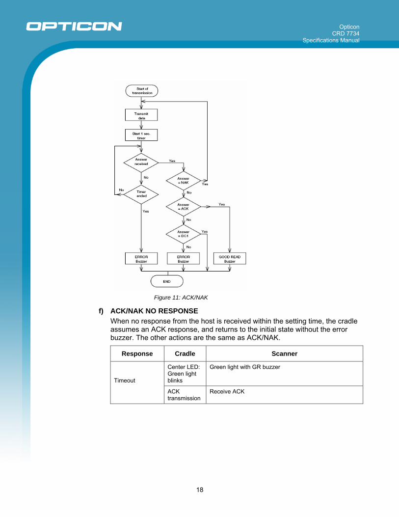
e) ACK/NAK After data has been transmitted, the cradle expects to receive one of the following responses from the host:
Control Level Notes ACK/NAK Protocol
Scanner, Cradle and Host Monitors response from the host.
Response Cradle Scanner
Center LED: Green light blinks Green light with GR buzzer ACK
ACK transmission Receive ACK
Center LED: Red light blinks Red light with NG buzzer NAK
NAK transmission Receive NAK
Center LED: Red light blinks Green light DC1
DC1 transmission Receive DC1
Center LED: Red light blinks Red light with ERROR buzzer Timeout
Timeout transmission Receive timeout
ACK/NAK timeout Menu / Command
Indefinitely (default) XI4
100 ms XI5
500 ms XI6
1000 ms XI7
Opticon CRD 7734
Specifications Manual
18
Figure 11: ACK/NAK
f) ACK/NAK NO RESPONSE When no response from the host is received within the setting time, the cradle assumes an ACK response, and returns to the initial state without the error buzzer. The other actions are the same as ACK/NAK.
Response Cradle Scanner
Center LED: Green light blinks
Green light with GR buzzer Timeout
ACK transmission
Receive ACK

Opticon CRD 7734
Specifications Manual
19
ACK/NAK timeout Menu / Command
Indefinitely (default) XI4
100 ms XI5
500 ms XI6
1000 ms XI7
Figure 12: ACK/NAK—No response
8.2. USB Interface Specifications The CRD 7734 supports a USB 1.1 full-speed interface. (Use EEPROM ver. 1.1)
To use the USB interface, it is necessary to install the virtual COM port (VCP) driver manufactured by Future Technology Devices Intl. Ltd. on the host computer.
The application on the host computer communicates data by accessing the VCP. The VCP is supported by the following operating systems:
• Microsoft Windows 98/98SE
• Microsoft Windows 2000/ME/XP/Vista
• MacOS 10.3

Opticon CRD 7734
Specifications Manual
20
Please refer to the instruction manual for detailed guidelines for installing the VCP driver.
The USB interface does not support USB bus power.
8.2.1. Interface Circuit
Figure 13: Interface circuit
8.3. IEEE 802.15.4
8.3.1. Radio Equipment The electromagnetic wave absorption (2.4 GHz) used by this product is also shared by various other devices. Therefore, baud rate and communication distance may be negatively impacted, or their communications may be disconnected, by other devices using the same absorption rate. Baud rate and communication distance are affected by obstacles, wave conditions, or a device at the other end. This product is equipped with an antenna. Bringing this product too close to a metallic object may affect communication. Anticipated interference distance is 10 m or less.
8.3.2. Frequency Band This product uses the 2.4 GHz frequency band. Scientific, medical, and industrial devices, including microwaves, wireless security (camera) systems and W-LAN use the same frequency band as this scanner. Other radio stations also use this frequency for mobile object identification, including local private radio stations that require a license (for example, manufacturing lines at factories), specific power-saving radio stations requiring no license, and amateur radio stations. Interference from other devices may affect the communication speed or communication range of this cradle or vice versa.

Opticon CRD 7734
Specifications Manual
21
9. Cable and Connector A dedicated RS-232C cable and a dedicated USB cable will be packaged with the CRD 7734.
9.1. RS-232C Cable Cable model no.: B04009-05
9.1.1. Pin Assignment
Pin Signal Remarks
1 RTS Flow control output
2 CTS Flow control input
3 TXD Data transmission to the host
4 RXD Data transmission from the host
5 NC Open (not connected)
6 GND
7 NC Open (not connected)
8 DSR Detection of interface
9 NC Open (not connected)
10 NC Open (not connected)
– FG
9.1.2. Connector 10-pin modular jack
9.2. USB Cable Cable model no.: B03006-11
9.2.1. Connector USB Type B Connector
9.2.2. Pin Assignment
Pin Signal Comment
1 VBUS Interface detection
2 -DATA
3 +DATA
4 GND

Opticon CRD 7734
Specifications Manual
22
10. Serial Number and Labeling The following labels are affixed to the specified location on the cradle.
Figure 14: Labeling (for OF1CR7734N)
Opticon CRD 7734
Specifications Manual
23
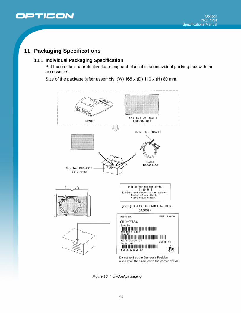
11. Packaging Specifications 11.1. Individual Packaging Specification
Put the cradle in a protective foam bag and place it in an individual packing box with the accessories.
Size of the package (after assembly: (W) 165 x (D) 110 x (H) 80 mm.
Figure 15: Individual packaging
Opticon CRD 7734
Specifications Manual
24
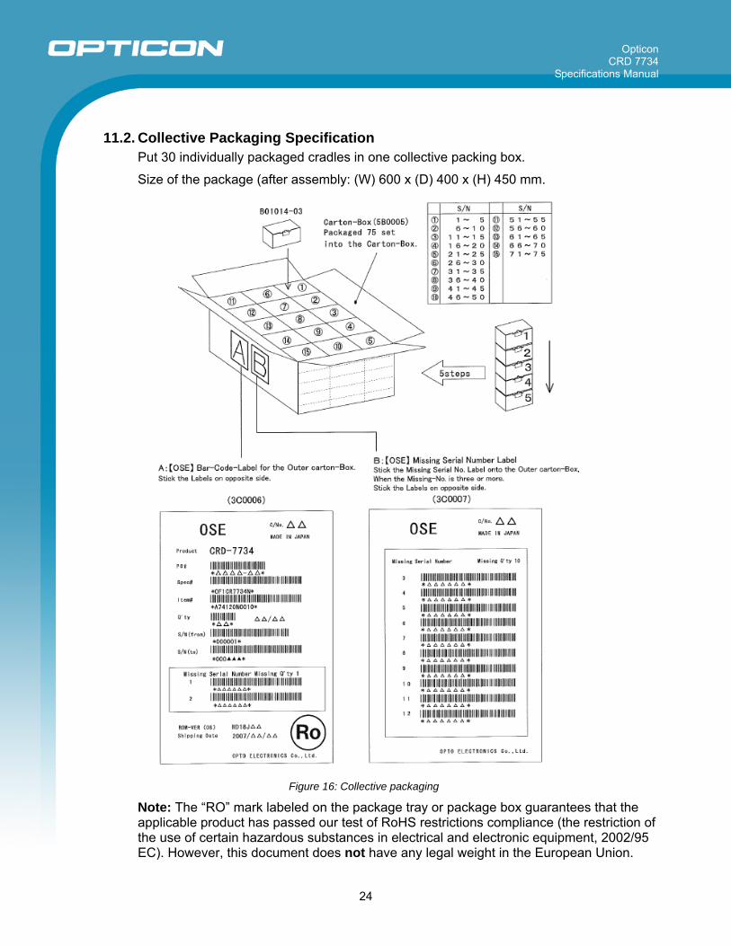
11.2. Collective Packaging Specification Put 30 individually packaged cradles in one collective packing box.
Size of the package (after assembly: (W) 600 x (D) 400 x (H) 450 mm.
Figure 16: Collective packaging
Note: The “RO” mark labeled on the package tray or package box guarantees that the applicable product has passed our test of RoHS restrictions compliance (the restriction of the use of certain hazardous substances in electrical and electronic equipment, 2002/95 EC). However, this document does not have any legal weight in the European Union.

Opticon CRD 7734
Specifications Manual
25
12. Durability 12.1. Static Electricity
Air discharge (No malfunction): ±8 kV max.
Air discharge (No destruction): ±15 kV max.
Indirect discharge (No malfunction): ±8 kV max.
Conditions Measurement environment: Use electrostatic testing device compliant with IEC 61000-4-2
Built up and discharged 15 kV of static electricity on the cradle surface 50 times.
Discharge resistance: 330 Ω
Capacitor charging: 150 pF
12.2. Shock
12.2.1. Drop Test (without packaging) No malfunction occurred after the following drop test. Drop Test: Drop the cradle from a height of 75 cm onto a concrete floor (once on each of 6 sides). Conditions • Tested units with scratches or dents on the casing pass the drop test.
• All tested units must operate correctly without malfunctions.
13. Reliability MTBF (Mean Time Between Failures) of the current-carrying parts is 62,100 hours.
The power supply terminals have an expected MTBF of 1,000,000 contacts.
The estimate of MTBF and product life cycle is based on standard operation of the product within the recommended temperature range and without extreme electronic or mechanical shock.
The MTTR (Mean Time To Repair) of this product is one hour.

Opticon CRD 7734
Specifications Manual
26
14. Regulatory Compliance 14.1. Product Safety
EN60950-1: 2001
IEC60950-1: 2001
14.2. EMC EN55022
EN55024
VCCI Class B: This is a Class B product, to be used in a domestic environment based on the Technical Requirement of the Voluntary Control Council for Interference from Information Technology Equipment (VCCI). If this is used near a radio or television receiver in a domestic environment, it may cause radio interference. Please install and use the equipment according to the instruction manual.
FCC Part 15 Subpart B Class B: This device complies with part 15 of the FCC Rules. Operation is subject to the following two conditions: (1) this device may not cause harmful interference, and (2) this device must accept any interference received, including interference that may cause undesired operation.
14.3. RoHS RoHS: The restriction of the use of certain hazardous substances in electrical and electronic equipment, 2002/95 EC.
14.4. R&TTE This cradle conforms to the following standards of the Radio and Telecommunications Terminal Equipment (R&TTE) directive from the EU.
EN300 328
EN301 489
14.5. Radio Law The cradle qualifies as radio equipment for low-power radio stations (2.4 GHz band advanced data communication systems) as specified in the Radio Law 38-24-1.
The cradle has obtained the Certification for Construction Design of Specified Radio Equipment. It does not have a radio station license in Japan.
The following activities are prohibited under the Radio Law:
• Remodeling and disassembly
• Peeling off the certificate label

Opticon CRD 7734
Specifications Manual
27
15. Safety Handle this product carefully. Do not deliberately subject it to any of the following.
15.1. Shock Do not throw or drop the scanner.
Do not drop or put heavy items on this product or its cable.
15.2. Temperature Conditions Do not use the cradle at temperatures outside the specified range.
Do not use near heat sources such as radiators, heat registers, stoves, or other types of devices that produce heat.
Do not use in areas exposed to direct sunlight for long periods of time.
Do not pinch or forcibly bend the cable, especially at very low temperature.
15.3. Foreign Materials Do not use the cradle near water or other liquids, as well as in extremely high humidity.
Do not immerse the cradle in liquids.
Do not use in dusty environments.
Do not subject the cradle to chemicals.
Do not insert foreign substances into the device.
15.4. Other Do not plug/unplug the connectors before disconnecting the power.
Do not attempt to disassemble, modify or update this device.
Do not use near microwaves, medical devices, or RF-emitting devices.
The cradle may not perform properly in environments when placed near a flickering light, such as a computer monitor, television, etc. Do not use in the reach of blinking lights such as CRT.
The cradle may be damaged by voltage drops.

Opticon CRD 7734
Specifications Manual
28
16. Mechanical Drawings
Figure 17: Mechanical drawing
Figure 18: Detailed view