communication cabling system standards
TRANSCRIPT
Townsville Campus Townsville Qld 4811 Australia Telephone (07) 4781 4111 International +61 7 4781 4111 www.jcu.edu.au
Document Number: Comm-Infra-20130801
Date: 5rd October 2017
Communication Cabling
System Standards
Intent To specify the communication cabling system standards at James Cook University.
Audience All staff and contractors working with communication cabling.
Contents Communication Cabling System Standards ........................................................................................................... 1
Intent .................................................................................................................................................................. 1
Audience ............................................................................................................................................................. 1
Contents ................................................................................................................................................................. 2
Part 1 - General ....................................................................................................................................................... 4
1.1 Introduction .................................................................................................................................................. 4
1.2 Authorization ................................................................................................................................................ 4
1.3 Applied Standards and James Cook University Requirements ..................................................................... 4
Part 2 - James Cook University Communication Cabling Special Requirements. ................................................... 5
2.1 Optical fibre cable, connectors and patch cords .......................................................................................... 5
2.1.1 Optical fibre. .......................................................................................................................................... 5
2.1.2 Optical fibre core quantities .................................................................................................................. 5
2.1.3 Optical fibre connectors ........................................................................................................................ 5
2.1.4 Optical fibre patch cords........................................................................................................................ 5
2.1.5 Blown Fibre ............................................................................................................................................ 6
2.2 Twisted Pair (TP) cable (STP/UTP) and Telecommunications outlets (TOs) ................................................. 6
2.2.1 TP cable category requirement ............................................................................................................. 6
2.2.2 TP cable termination scheme ................................................................................................................ 6
2.2.3 Backbone Cabling ................................................................................................................................... 6
2.2.4 Horizontal cabling and Wall Outlets ...................................................................................................... 7
2.2.5 Patch panels ........................................................................................................................................... 7
2.2.6 Patch cords ............................................................................................................................................ 7
2.3 Communications Rooms ............................................................................................................................... 7
2.3.1 New Buildings ........................................................................................................................................ 7
2.3.2 Size of communication rooms. .............................................................................................................. 8
2.3.3 Arrangement layout of cabinet/rack (Building Distribution, Floor Distribution) ................................. 12
2.3.4 Internal Rack Cabling ........................................................................................................................... 18
2.3.5 Rack Cable Entry .................................................................................................................................. 26
2.3.6 Vertical cable position ......................................................................................................................... 28
2.3.7 Front and rear mounting rails .............................................................................................................. 28
2.3.8 Cable slack ........................................................................................................................................... 28
2.3.9 Communications Racks ........................................................................................................................ 28
2.3.10 Power ................................................................................................................................................. 29
2.3.11 Reserved Space .................................................................................................................................. 29
2.3.12 Compliance Checklist ......................................................................................................................... 30
2.3.13 Request for Variation to Standard ..................................................................................................... 31
2.4 Communications Earth ............................................................................................................................... 32
2.5 Labeling ....................................................................................................................................................... 32
2.5.1 Material and size.................................................................................................................................. 32
2.5.2 Telecommunication outlets ................................................................................................................. 33

2.5.3 Rack ...................................................................................................................................................... 33
2.5.4 Optical fibre ......................................................................................................................................... 34
2.5.5 Label size .............................................................................................................................................. 36
2.6 Testing ........................................................................................................................................................ 37
2.6.1 Horizontal UTP cabling ......................................................................................................................... 37
2.6.2 Optical fibre cabling ............................................................................................................................. 37
2.6.3 Outdoor voice UTP backbone cabling .................................................................................................. 37
2.6.4 Indoor Riser Voice UTP cabling ............................................................................................................ 37
2.7 Outdoor & Wall Cabling .............................................................................................................................. 38
2.7.1 Conduit ................................................................................................................................................ 38
2.7.2 Cable and conduit supports ................................................................................................................. 38
2.7.3 Skirting ducts ....................................................................................................................................... 39
2.7.4 Cable pits ............................................................................................................................................. 39
2.7.5 Trenching ............................................................................................................................................. 40
2.7.6 Cable in trenches ................................................................................................................................. 40
2.7.7 Backfilling trenches .............................................................................................................................. 40
2.8 Administration ............................................................................................................................................ 41
2.8.1 Documents ........................................................................................................................................... 41
2.8.2 Recording ............................................................................................................................................. 41
2.9 Installer and System Warranty ................................................................................................................... 41
2.10 Recommended Documents ...................................................................................................................... 41
2.11 Terms and Abbreviations .......................................................................................................................... 42
Part 3 - Acknowledgements .................................................................................................................................. 43
Part 4 - Document Information ............................................................................................................................ 44

Part 1 - General
1.1 Introduction The purpose of this document is to set the communications cabling standards for installation and alterations including data, voice, video conferencing and security at James Cook University. It is based on Balanced Twisted Pair Technology and Optical Fibre Cabling Technology.
Our vision for the network is:
The Local Area Network provided to the Students, Staff and Researchers at James Cook University is pervasive and seamless, providing effortless and reliable access to networked data resources from within James Cook University and around the world. The Local Area Network enables the University to enhance its standing as a leading Tropical Learning and Research Institution.
Information Communications Technology Directorate provide a Local Area Network that forms the cornerstone of the outstanding communication systems integrated into Learning, Teaching, Research and Engagement. The inherent flexibility and robustness of the Local Area Network enables exceptional service and efficiency that is espoused by Students, Academic Staff, Professional Staff and Industry Peers.
As the network, cabling forms the backbone of the network and is an essential component, adherence to standards during installation and modification is critical. The scope of this document will include the installations, extensions and modifications of existing cabling within the campus.
This document provides Standards, Requirements and Recommended Documents that provide all aspects of planning, design, installation, testing and administration of cabling system technology for James Cook University.
1.2 Authorization All permanently installed data and voice cabling inside buildings and between buildings is part of the University communications infrastructure administered by ICT (Information Communication Technology Directorate).
Any proposed alteration to the cabling standard must be submitted to the Head, ICT Infrastructure Services Section for approval.
1.3 Applied Standards and James Cook University Requirements All Structured Cabling work shall be installed in strict compliance with the James Cook University Communications Cabling Infrastructure specifications and to the latest Australian standards as listed below. The installer must be capable of providing a minimum 15-year manufacturer’s warranty on all installations.
For existing buildings on the Douglas Campus, compliance with the latest TE Connect specification is applicable (available at www.adckrone.com.au).
For existing buildings on the Cairns Smithfield Campus, compliance with the latest Molex standard is applicable (available www.molexpn.com).
International standards shall be referred to where there is no applicable Australian Standard.
In the case of conflicting specifications, the higher specification will be adopted. The Head, ICT Infrastructure Services Section, JCU must approve any deviation from these standards.
AS/NZS 3080: 2013 or later
"Telecommunications installations – Integrated telecommunications cabling systems for commercial premises" shall be conformed to for the communication cabling of James Cook University.
AS/CA S009:2013
"Installation requirements for customer cabling" shall be mandatory for the communication cabling of James Cook University.
AS/NZS 3084:2017 or later
"Telecommunications installations – Telecommunications pathways and spaces for commercial premises" shall be conformed to the communication spaces of James Cook University.
Current TE Connect standards
For TE Connect standards (refer te.com/enterprise). Douglas Campus Only.
Current Molex standards
For Molex Standards (refer www.molexpn.com). Smithfield Campus Only.
Part 2 - James Cook University Communication Cabling Special Requirements.
2.1 Optical fibre cable, connectors and patch cords
2.1.1 Optical fibre.
All installations of optic fibre will be OS1 Single-mode. All installations shall follow the existing Infrastructure pathways if available and must be specified in the planning stages in consultation with the Head, ICT Infrastructure Services Section, JCU.
2.1.2 Optical fibre core quantities
Optical fibre cable shall be installed with a minimum of 12-core single-mode between any two-termination points (Racks). Smaller configurations may be considered for use in low-density buildings after consultation with the Head, ICT Infrastructure Services Section, JCU.
2.1.3 Optical fibre connectors
University Campus infrastructure is installed using SC connectors.
The SC connector shall comply with AS/NZS 3080: 2013 or later.
2.1.4 Optical fibre patch cords
Color of Optical fibre patch cords
Single-mode: YELLOW
Multimode: Orange OM1-OM2, Light Blue OM3
2.1.5 Blown Fibre
All new fibre connections to and between buildings and from the main building entry point to floor distributors shall be completed using blown fibre in Direct Install (DI) blown fibre duct.
New DI duct between Major network nodes shall contain 19 tubes.
New DI duct to and between other buildings and to floor distributors shall contain at least seven tubes.
The specifications for the fibre cores remain as specified elsewhere in this document.
All tubes in a DI duct are to be terminated on a Tube Management Panel (TMP) mounted on the rear rails of cabinet where possible. As described in section 2.3.4 Internal Rack Cabling.
All fibres are to be terminated as specified in section 2.3.4 Internal Rack Cabling
All DI duct is to be labeled in every pit and every cabinet with designations supplied by ITR.
All unused tubes are to be sealed with end caps.
Bare tubes to be retained by Velcro straps, not less than 6mm wide.
All inter-floor or inter-communications closet cabling shall utilize optic fibre connectivity. The standard 12-core single-mode shall apply.
All cabling shall be supported to and within the rack via cable trays. NO cabling or tubing is to be attached to cabinet mounting rails.
2.2 Twisted Pair (TP) cable (STP/UTP) and Telecommunications outlets (TOs) In all cases, the use of cable ties is not permitted for securing cable (Fibre and Copper).
Where Category 6 is specified in this document, this will include Category 6a (ISO/IEC: 11801:2002 Class EA).
With the distribution of the document, (April 2017) the minimum accepted cable shall be Category 6A shielded construction (STP).
All cabling shall be supported to and within the rack via cable trays. NO cabling is to be attached to cabinet mounting rails.
All external cable, conduit-in-slab cable or cable likely to be subject to prolonged exposure to water shall be of moisture barrier construction.
2.2.1 TP cable category requirement
All new TP cabling for all campuses shall be installed using Category 6a STP products (ISO/IEC: 11801:2002 Class E). Termination of Category 6a STP cables on spare ports of existing Category 5 panels is acceptable for older installations. Where spare Category 5 panel ports are not available Category 6a STP products shall be used.
2.2.2 TP cable termination scheme
TP cable termination scheme shall be the T568A. (Refer AS/NZS 3080: 2013 Annex ZA).
2.2.3 Backbone Cabling
The communications cabling between Building Distributor and Floor Distributor shall be installed with a minimum of 50% spare capacity above project requirements to allow for future expansion.
The building Fibre Distributors shall NOT be connected in daisy chain configuration but directly cabled to the principal Building Distribution Rack, on the ground floor of the building.
All external cable, conduit in-slab cable or cable likely to be subject to prolonged exposure to water shall be of moisture barrier construction
2.2.4 Horizontal cabling and Wall Outlets
Quantity of Wall Outlets
In office space, 2 per workstation.
In laboratory space, 2 per computer workspace + 20%.
Wireless Access Points, 2 per unit.
Consideration must be given to providing Wall Outlets for:
Data Projectors, Cameras, Wireless Access points, Door Access Controllers, video displays, Building Management Systems ETC.
Category of Wall Outlets
For new buildings or complete rewiring, Category 6a STP shall be used.
All external cable, conduit in-slab cable or cable likely to be subject to prolonged exposure to water shall be of moisture barrier construction
2.2.5 Patch panels
Category 6a STP patch panels must be used.
For new buildings or complete rewiring, Category 6a STP patch panels shall be used.
All Category 6a STP patch panels shall be of 24-port capacity on a single row.
The telephony integration panel may be of 48-port construction.
2.2.6 Patch cords
Category 6a STP patch cords must be used.
Color of patch cords
General purpose
Blue: For Ethernet use.
Special purpose
Yellow: For Analogue Telephone services.
2.3 Communications Rooms Any variation to the standards detailed in this document must be submitted to the Head, ICT Infrastructure Services Section, JCU. The form in section 2.3.12 must be submitted for approval with details of the requested variation. The checklist in Section 2.3.13 will be used to assess compliance with these cabling standards.
2.3.1 New Buildings
All new buildings are required to have at least two separate entry points for communications cabling. Each entry point shall have at least two 100mm conduits that enter the building with clear access to the building’s “service space”.
Where the likelihood the usage of the building will be for multiple tenancies, three 100mm conduit shall be provide via each alternate direction into the common riser space. (Six conduits in total)
Conduits that enter a communications room must be outside the communications cabinets and a cable support installed.
All buildings are required to be connected back to the local fibre network precinct via two geographically diverse paths.
All buildings are required to be provided with copper cabling for analogue services. This must be connected back to the existing campus cabling interconnects.

All communications rooms shall be finished with products that minimize dust and ingress of pests. All rooms shall have enclosed ceilings.
All communications rooms shall be provided with ventilation or air-conditioning capable of maintain a stable air temperature of 25 degrees Celsius, 80% Relative Humidity or less as measured at the front of the rack with all doors closed. In new buildings the main communications room must be provided with a standalone air-conditioner The minimum height floor to ceiling for all communications rooms shall be a minimum 2400 millimeters.
A minimum of 1 communications room per floor shall be provided
The communications rooms are primarily dedicated to communications services. Any additional services that require installation in the communications rooms must be discussed with the Head, ICT Infrastructure Services Section, JCU. This includes Building management, Security systems, Door access, ETC.
No Electrical switch boards or UPSs shall be located with the communications room unless directly related with the communications infrastructure and must be approved by the Head, ICT Infrastructure Services Section, JCU..
Cabinet doors within the communications room shall be operable without restriction by door frames or walls surrounding the enclosure.
All communications room shall be keyed to the communications master system and shall have a proximity card access system installed.
2.3.2 Size of communication rooms.
The following diagrams show the minimum clear space allowable for a communications room/closet. Relative dimensions are taken from:
AS.CA S009:2013: Installation requirements for customer cabling, Section 13.6 and Appendix D.
Managing the work Environment and Facilities, code of practice, December 2011, Section 2.1.
2.3.2.1 Smaller rooms.
This diagram shows the minimum space to be allocated to a communications cabinet.
Notes for smaller rooms:
900mm clear access is required to the side of the cabinets.
Cabinets require 200mm clearance to the wall and 300mm clearance to the door.
The minimum clear access to the sides of the cabinet must be 600 mm. (Corner of cabinet to wall.)
The door on the cabinet must be able to be opened to at least 104 degrees without impedance. (Calculated by the leading edge of the door moving 200mm beyond 90 deg)
The door to the room must be of sufficient width to allow the cabinet to be removed from the room. (800mm minimum.)
The door to the room must be of sufficient height to allow removal of the cabinet. (Minimum of 2100mm.)
Wall mounted equipment is only allowed in the green locations as shown. (EG, BMS, Door Access) and must maintain 900mm clearance to Rack.
2.3.2.2 Larger Rooms.
This diagram shows the restricted space surrounding communications racks in larger rooms. When more than two cabinets are required a large room is required. It is not acceptable to mount three cabinets against a wall.
Notes for larger rooms:
The entry to the room must provide 1200mm clearance to the cabinets.
The rear of the cabinets must have 900mm clearance.
Wall equipment must not extend into these spaces, unless it is over 2100mm above floor level.
The door on the cabinet must be able to be opened to 104 degrees without impedance. (Calculated at the edge of the door moving 200mm beyond 90 degrees)
The door to the room must be of sufficient width to allow the cabinet to be removed from the room. (800mm minimum.)
The door to the room must be of sufficient height to allow removal of the cabinet. (Minimum of 2100mm.)
900mm clear floor space required at the end of the racks.
Racks must not have a gap between the racks. Racks must be secured together.
2.3.2.3 Wall clearances.
This diagram shows the restricted wall space surrounding communications racks.
Notes for wall clearances:
No items may be mounted on the walls above the reserved floor space, below 2100mm.
Any roof mounted equipment must not be above the rack if it reduces the clearance above the rack.
Wall equipment must not extend into these spaces, unless it is over 2100mm above floor level.
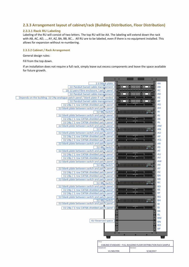
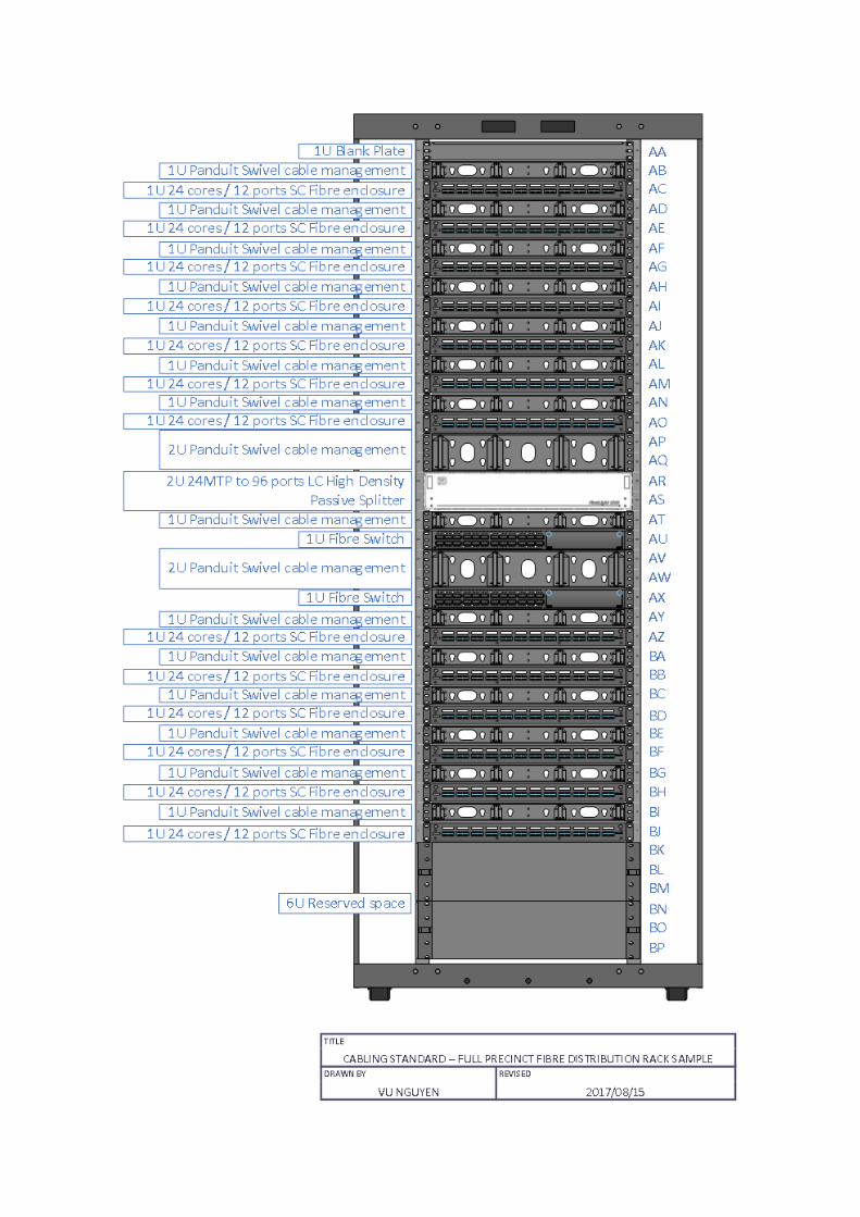
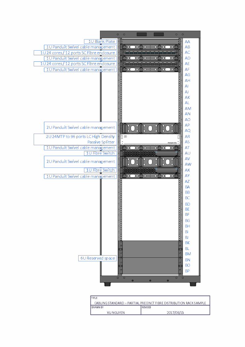
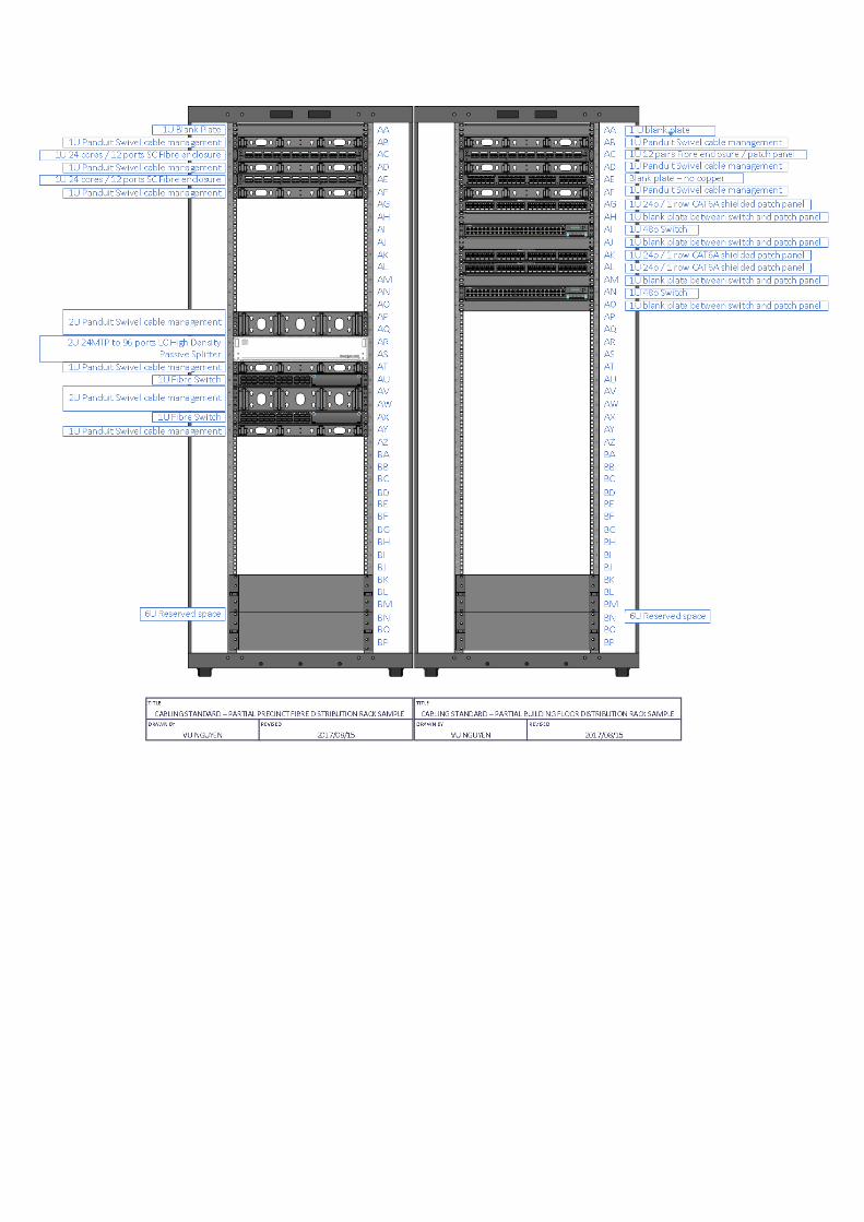
2.3.3 Arrangement layout of cabinet/rack (Building Distribution, Floor Distribution)
2.3.3.1 Rack RU Labeling Labeling of the RU will consist of two letters. The top RU will be AA. The labeling will extend down the rack with AB, AC, AD, …, AY, AZ, BA, BB, BC... All RU are to be labeled, even if there is no equipment installed. This allows for expansion without re-numbering.
2.3.3.2 Cabinet / Rack Arrangement
General design rules:
Fill from the top down.
If an installation does not require a full rack, simply leave out excess components and leave the space available for future growth.
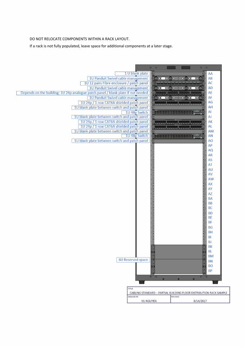
DO NOT RELOCATE COMPONENTS WITHIN A RACK LAYOUT.
If a rack is not fully populated, leave space for additional components at a later stage.
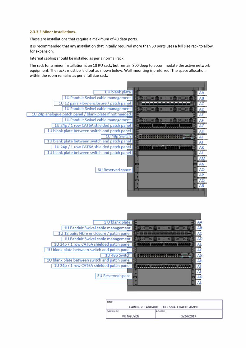
2.3.3.2 Minor Installations.
These are installations that require a maximum of 40 data ports.
It is recommended that any installation that initially required more than 30 ports uses a full size rack to allow for expansion.
Internal cabling should be installed as per a normal rack.
The rack for a minor installation is an 18 RU rack, but remain 800 deep to accommodate the active network equipment. The racks must be laid out as shown below. Wall mounting is preferred. The space allocation within the room remains as per a full size rack.
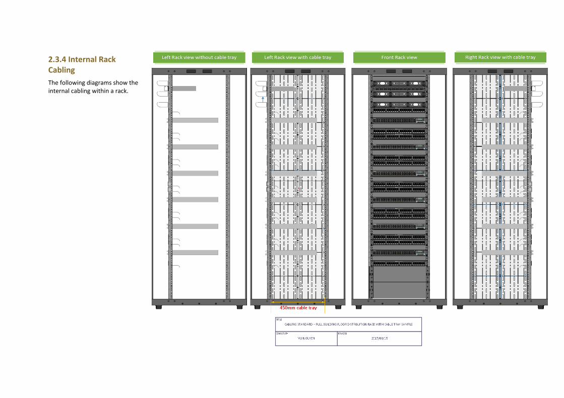
2.3.4 Internal Rack Cabling
The following diagrams show the internal cabling within a rack.

2.3.4.1 Notes for Internal Rack Cabling
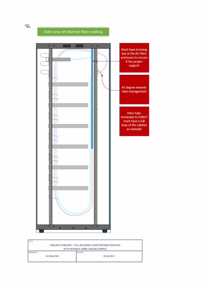
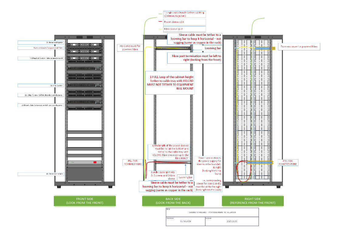
Fibre cabling, The sheath of a DI tubing cable must be removed no closer than 300mm to the commencement of the bend at the bottom of the rack. The fibre cable and tubing must be secured to the Cable tray by Velcro straps at no more than 500mm intervals. All DI tubing must pass through or terminate on a tube management panel The Tube management panel is mounted inward at 45 degrees so the terminal points are accessible from within the cabinet. All DI tubing terminating on the tube management rail must be capped. All tubes terminating on a FOBOT must have a full loop within the cabinet. This allows the FOBOT to be removed from the cabinet and placed on a table during fibre termination work. Tubes between the Tube management panel and a FOBOT must be secured separately from the incoming DI fibre, using Velcro straps. The initial DI tubing must be installed so that an additional DI tube can be installed without relocation.
DI and tubing MUST NOT be tethered to 19”mounting rails
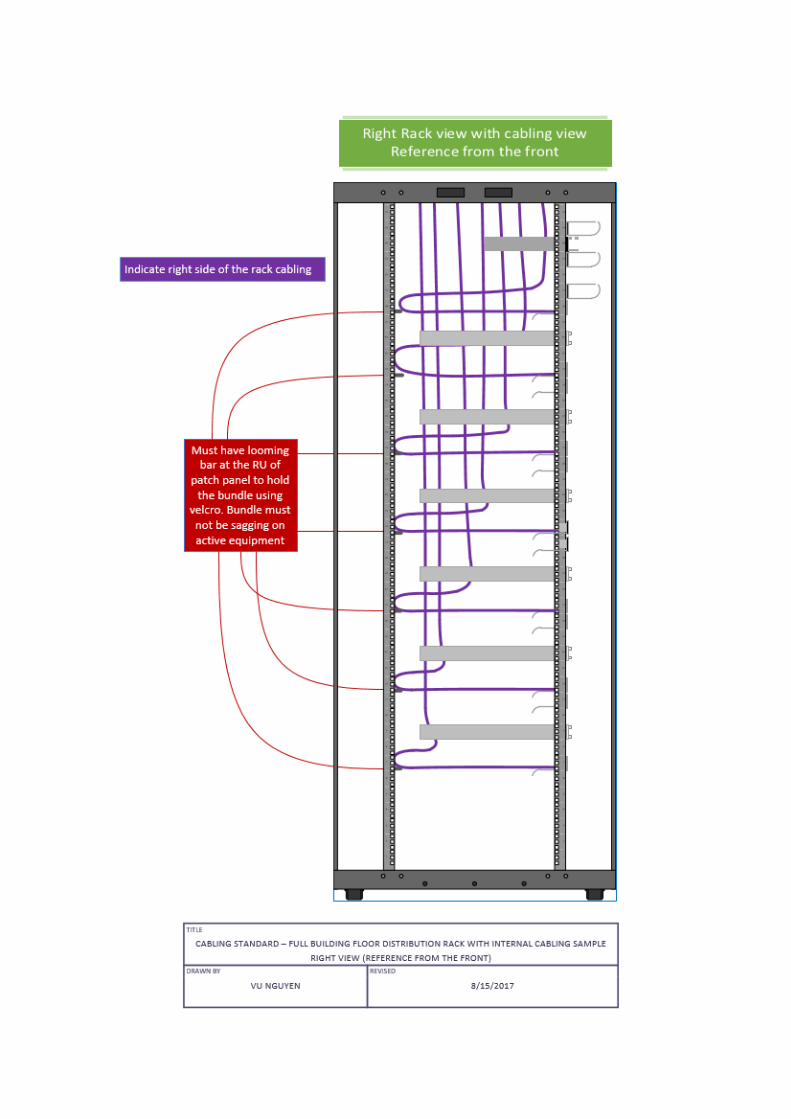
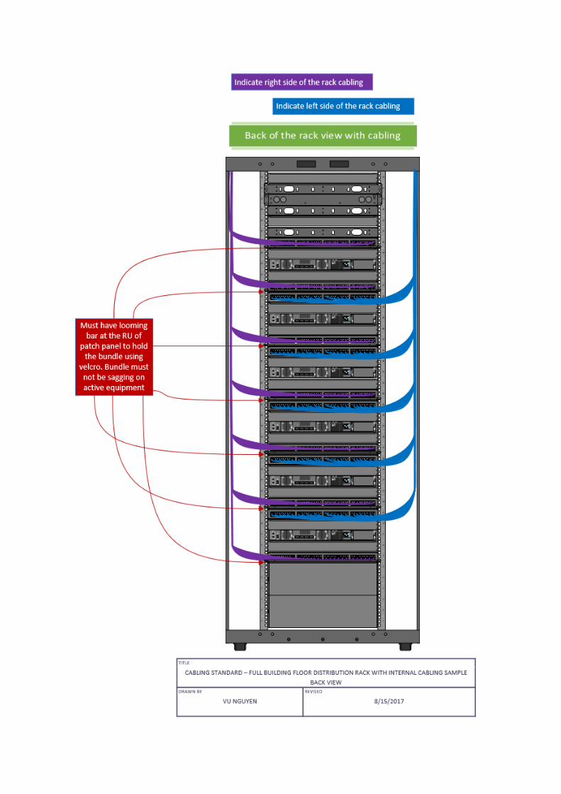
Copper Cabling The initial eight cable looms shall be located to the right-hand cable tray. For a high density rack to cable looms (9 – 12) shall be tethered to the left-hand cable tray The cabling shall be secured to the rack at random intervals between 200 - 300mm with 6mm or wider Velcro straps. Random Lay In bundles of not more than 24 cables and Combing is not permitted. The cabling must enter the top of the rack and the bundles be secured to the cable tray at 50mm between centers.
The cable looms are not be allowed to sag into the space allocated to switching or other electronic equipment. Looms shall be supported at the rear of the rack by heavy duty lacing bars installed on the rear 19” rack rails.
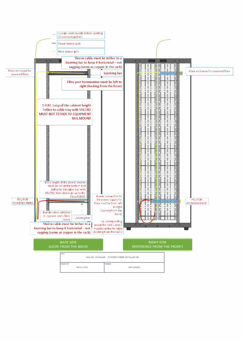
Powered Fibre Cabling ,,,,,,
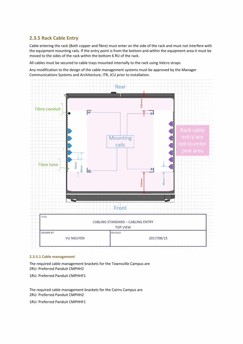
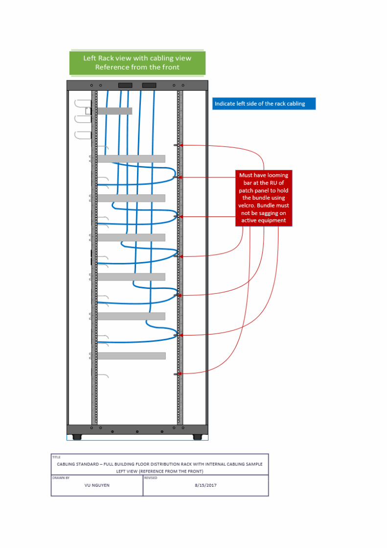
2.3.5 Rack Cable Entry
Cable entering the rack (Both copper and fibre) must enter on the side of the rack and must not interfere with the equipment mounting rails. If the entry point is from the bottom and within the equipment area it must be moved to the sides of the rack within the bottom 6 RU of the rack.
All cables must be secured to cable trays mounted internally to the rack using Velcro straps
Any modification to the design of the cable management systems must be approved by the Manager Communications Systems and Architecture, ITR, JCU prior to installation.
2.3.5.1 Cable management
The required cable management brackets for the Townsville Campus are 2RU: Preferred Panduit CMPHH2
1RU: Preferred Panduit CMPHHF1
The required cable management brackets for the Cairns Campus are 2RU: Preferred Panduit CMPHH2
1RU: Preferred Panduit CMPHHF1
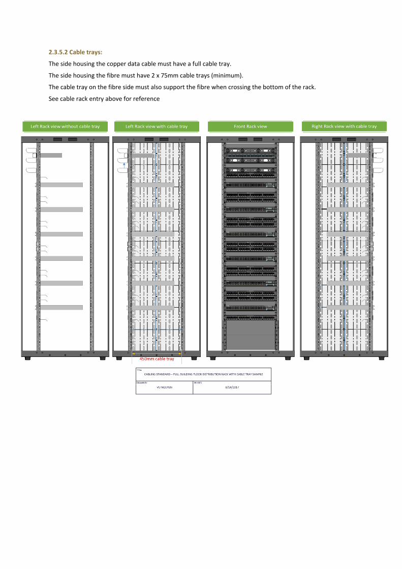
2.3.5.2 Cable trays:
The side housing the copper data cable must have a full cable tray.
The side housing the fibre must have 2 x 75mm cable trays (minimum).
The cable tray on the fibre side must also support the fibre when crossing the bottom of the rack.
See cable rack entry above for reference
2.3.6 Vertical cable position
Vertical cable within a cabinet shall NOT protrude into the active equipment area (between mounting rails). Should the cable enter the rack from below, it must clear the space between the mounting rails within the bottom 6 RU of the rack.
2.3.7 Front and rear mounting rails
All communication cabinets shall be supplied with front and rear mounting rails.
The mounting rails shall be installed to provide a minimum 150 mm space at the front of the rack and 100mm at the rear of the rack. See diagram ‘Top of Rack views’ section 3.4
2.3.8 Cable slack
All slack cable shall be stored near the rack: No coils are permitted for copper cable.
UTP cable: 1m slack. Optical fibre cable: 2m slack at each end.
The slack cable must be left in the ceiling or under the floor.
All cabling within a rack shall be secured to cable trays and no slack shall exist within the rack.
2.3.9 Communications Racks
Racks shall be secured to the floor to prevent tipping of the cabinet.
The front and back of the rack shall have vented doors.
Both front and back doors must be lockable.
Side panels must be provided and attached to any accessible side. If two racks are joined the internal side panels are to be let off. Any side against a wall is not required to have a panel or door attached.
Rack Dimensions Notes
800mm (w) x 800mm (d) Minimum dimensions for a communications rack. All diagrams show this dimension rack.
600mm wide racks Only acceptable for 18RU racks. 600mm wide racks must be 800mm deep.
1000mm deep racks and 1200mm deep racks.
Acceptable. The additional depth will require a corresponding increase in the depth of the room.
The capacity of a communications rack is limited by the available space for patching, fibre termination and active equipment to support the patching. The following table provides the maximum number of ports to be allocated to a Rack.
Number of outlets supported. Cabinet size and detail
0-48 Outlets 18RU floor mounted cabinet, minimum 800 mm deep.
49-192 Outlets 1 x 42RU 800x800mm Cabinet
193 + Outlets 1 additional 42RU 800x800mm cabinet per 192 outlets or part thereof. Refer HD Rack

2.3.10 Power
2.3.10.1 Rack Power Supply
All racks must be provided with two 15A circuits, dedicated to the racks. These must be mounted in close proximity to the rack, allowing power to be isolated without contacting the rack.
Outlets must be wall mounted switched, 15A outlets. (Recommended Clipsal 56C315)
In all new buildings the ground floor communications room must be equipped with a distribution board that supplies power to all communications rooms in the building. This board is to have two supplies, ‘A’ and ‘B’. A is to be supplied from a building UPS (if applicable) or a direct feed from the building supply. The ‘B’ supply is to be provided with a generator backup changeover in the event of a power failure (if available). The ‘B’ supply must also allow for the insertion of a rack mounted UPS of sufficient capacity to maintain the active network equipment in the event of a power failure until the generator is on-line.
Surge Diversion must be provided on all power circuits.
2.3.10.2 Power Distribution Units (PDU)
A minimum of two power rails must be provided within the racks. Each rail must be supplied from a separate circuit from the switchboard. These circuits must be dedicated to the communications cabinets.
The rack power rails shall be connected to the power circuits by an industrial captive type plug socket.
2.3.10.4 Location of PDU Power Rails must be mounted at the position shown on the internal cabling diagram. If the cabinet is mounted with only side access the power rail outlets face toward the front of the rack. If the rack has rear access the power rail outlets must face the rear of the rack.
2.3.11 Reserved Space
The top 2 RU on the front of the cabinet is to be covered by a 1U blanking plate and a 1U cable management.
The bottom 6RU of a cabinet shall be covered by a blanking plate. (2 x 3RU Plates.)
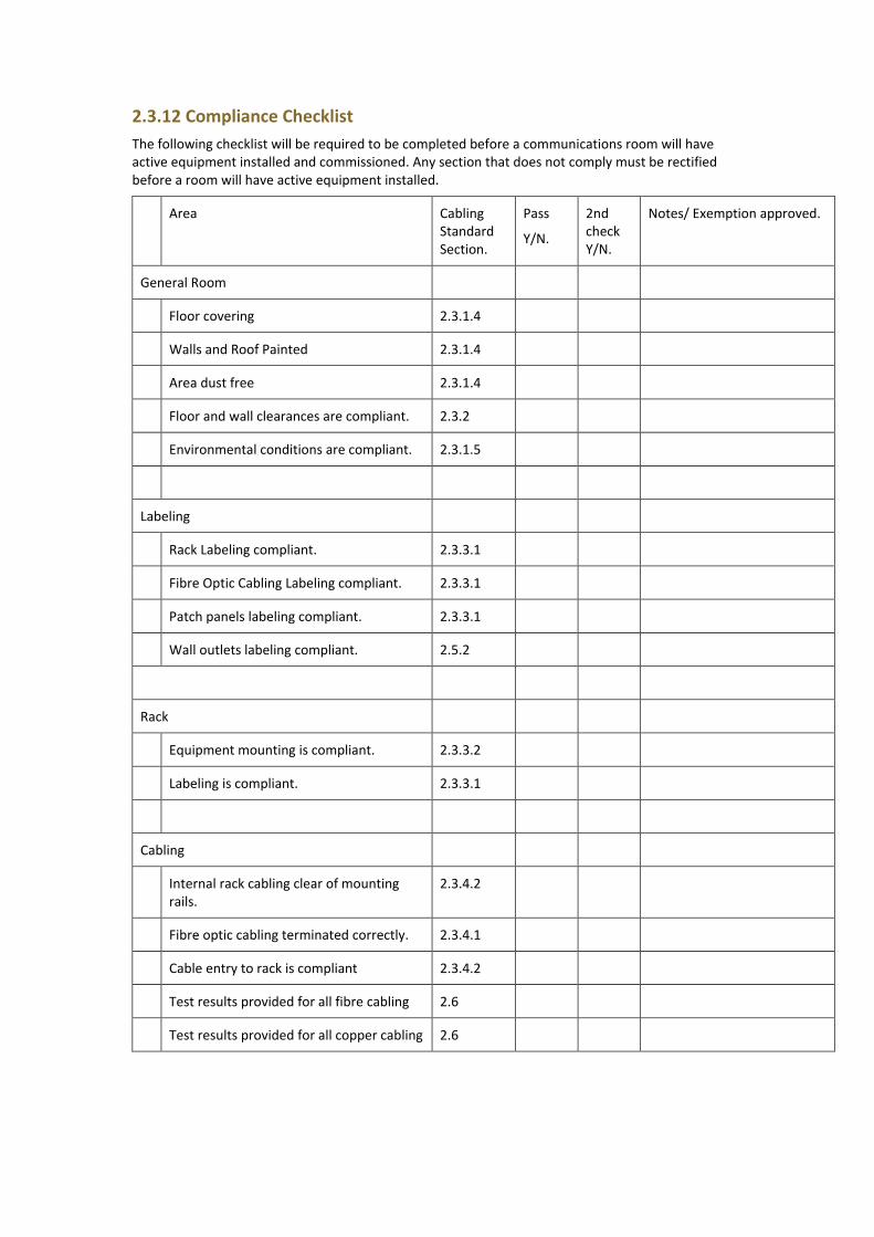
2.3.12 Compliance Checklist
The following checklist will be required to be completed before a communications room will have active equipment installed and commissioned. Any section that does not comply must be rectified before a room will have active equipment installed.
Area Cabling Standard Section.
Pass
Y/N.
2nd check Y/N.
Notes/ Exemption approved.
General Room
Floor covering 2.3.1.4
Walls and Roof Painted 2.3.1.4
Area dust free 2.3.1.4
Floor and wall clearances are compliant. 2.3.2
Environmental conditions are compliant. 2.3.1.5
Labeling
Rack Labeling compliant. 2.3.3.1
Fibre Optic Cabling Labeling compliant. 2.3.3.1
Patch panels labeling compliant. 2.3.3.1
Wall outlets labeling compliant. 2.5.2
Rack
Equipment mounting is compliant. 2.3.3.2
Labeling is compliant. 2.3.3.1
Cabling
Internal rack cabling clear of mounting rails.
2.3.4.2
Fibre optic cabling terminated correctly. 2.3.4.1
Cable entry to rack is compliant 2.3.4.2
Test results provided for all fibre cabling 2.6
Test results provided for all copper cabling 2.6
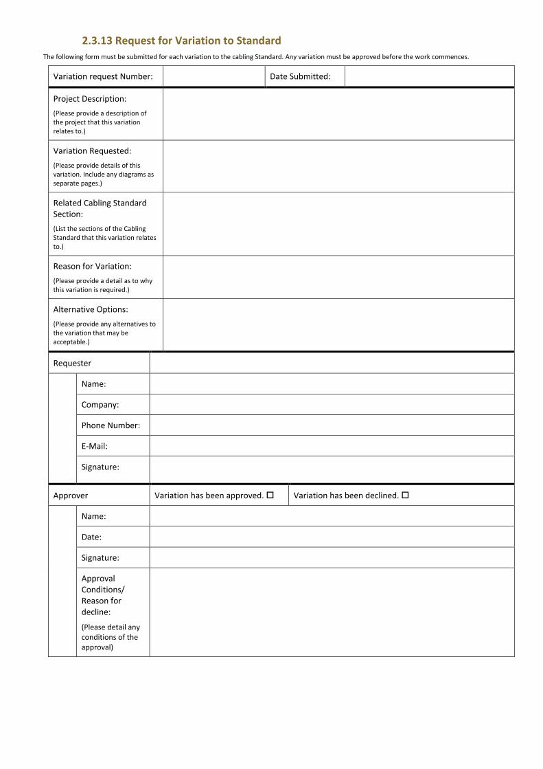
2.3.13 Request for Variation to Standard The following form must be submitted for each variation to the cabling Standard. Any variation must be approved before the work commences.
Variation request Number: Date Submitted:
Project Description:
(Please provide a description of the project that this variation relates to.)
Variation Requested:
(Please provide details of this variation. Include any diagrams as separate pages.)
Related Cabling Standard Section:
(List the sections of the Cabling Standard that this variation relates to.)
Reason for Variation:
(Please provide a detail as to why this variation is required.)
Alternative Options:
(Please provide any alternatives to the variation that may be acceptable.)
Requester
Name:
Company:
Phone Number:
E-Mail:
Signature:
Approver Variation has been approved. Variation has been declined.
Name:
Date:
Signature:
Approval Conditions/ Reason for decline:
(Please detail any conditions of the approval)
2.4 Communications Earth A communication earth system shall be provided to each rack (Refer AS/ANZ 3000, AS/CA S009:2013 & AS/NZS 3080:2013 or latest revision).
2.5 Labeling
2.5.1 Material and size.
Laminated (p-touch) labeling is to be used at Wall outlets, Rack, Patch panel and Cable.
316 Stainless steel or better with laser etched letters tag for optical fibre cable and copper trunk cable.
Large size labels would be preferred.
2.5.1.1 Cairns
Building Numbers
All building numbers will consist of a “C” followed by building identifier (Precinct and two numbers). EG CE01 or CB02. Do not use one number in the building identifier, EG CE1 or CB7
Floor Numbers
The Ground floor is designated as ‘0’.
Communication Room Designation
Communication Rooms on the floor is numbered starting from “1”: 1, 2, 3,... If there is only 1 room on the floor, the default label “1” shall be applied.
Rack count identification in the same room
The rack count using letters starting with “A”: A, B, C, D. If there is only 1 rack, the default “A” label shall be applied.
Rack RU Identification
The labelling runs from the top of the rack to the bottom. It consists of two Letters commencing with ‘AA’ in the progression: AA, AB, AC, AD … AZ, BA, BB, BC…
2.5.1.2 Townsville
Building Numbers.
All building numbers will consist of a “T” followed by three numbers. EG T001 or T500. Do not use “T” followed by one or two numbers, EG T1 or T27.
Floor Numbers.
The Ground floor is designated as ‘0’.
Communication Room Designation
Communication Rooms on the floor is numbered starting from “1”: 1, 2, 3,... If there is only 1 room on the floor, the default label “1” shall be applied.
Rack count identification in the same room
The rack count using letters starting with “A”: A, B, C, D. If there is only 1 rack, the default “A” label shall be applied.
Rack RU identification
The labelling runs from the top of the rack to the bottom. It consists of two Letters commencing with ‘AA’ in the progression: AA, AB, AC, AD … AZ, BA, BB, BC…
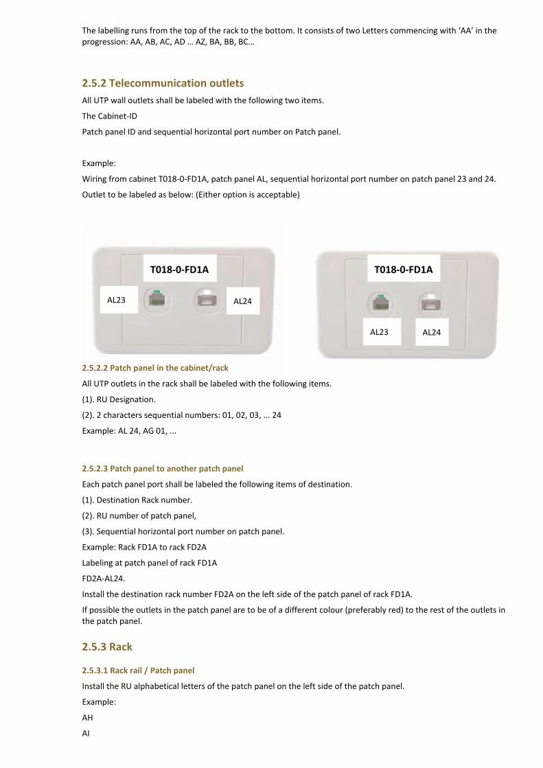
2.5.2 Telecommunication outlets
All UTP wall outlets shall be labeled with the following two items.
The Cabinet-ID
Patch panel ID and sequential horizontal port number on Patch panel.
Example:
Wiring from cabinet T018-0-FD1A, patch panel AL, sequential horizontal port number on patch panel 23 and 24.
Outlet to be labeled as below: (Either option is acceptable)
2.5.2.2 Patch panel in the cabinet/rack
All UTP outlets in the rack shall be labeled with the following items.
(1). RU Designation.
(2). 2 characters sequential numbers: 01, 02, 03, ... 24
Example: AL 24, AG 01, ...
2.5.2.3 Patch panel to another patch panel
Each patch panel port shall be labeled the following items of destination.
(1). Destination Rack number.
(2). RU number of patch panel,
(3). Sequential horizontal port number on patch panel.
Example: Rack FD1A to rack FD2A
Labeling at patch panel of rack FD1A
FD2A-AL24.
Install the destination rack number FD2A on the left side of the patch panel of rack FD1A.
If possible the outlets in the patch panel are to be of a different colour (preferably red) to the rest of the outlets in the patch panel.
2.5.3 Rack
2.5.3.1 Rack rail / Patch panel
Install the RU alphabetical letters of the patch panel on the left side of the patch panel.
Example:
AH
AI
T018-0-FD1A
AL23 AL24
T018-0-FD1A
AL23 AL24
AL
AM
2.5.3.2 Rack
Label shall be installed in the middle top at the rack with the following format:
Building number – Floor – FD Communication Room Designation Rack Count identification
Example:
T018 – 0 – FD 1 A
Additional racks in the same room will be suffixed with an alphabetic symbol ie B, C, D
Examples:
Rack: T018-0-FD3A, T004-1-FD1A, T003-0-FD5A
Note: Ground floor will be ‘0’ for the Floor number and Cairns may replace the letters “FD” with “BD”..
2.5.4 Optical fibre
2.5.4.1 Label size, material and format
Size: In patch panel, the size of label no less than 3. cm x 2.5 cm at 1 RU patch panel.
Material: On the cable, laser etched 316 stainless steel tag must be used.
Format:
- Cable path format must be: CABINET DESIGNATION<>CABINET DESIGNATION.
- Pit connection format must be: Pit number-pit number-pit number-etc in 3 characters format
- Floor connection format must be: F<floor number>-pit number (if requires)-F<floor number>-etc
- Each optical fibre cable shall be tag in the pit and near the FOBOT at both end with cable path, pit path using pit numbers and must also be labeled “Optical Fibre – Caution” with a contact phone number for ICT, in order to indicate the optical fibre identity.
Please confirm with ICT if you are unsure.
2.5.4.2 Campus optical fibre cable and patch panel
Label the following information in the patch panel and on the cable near the patch panel.
Patch panel format and example:
Cable tag format and example:
If the cable has been spliced, then the destinations must be labeled at either end of patch panel and cable to show the final termination point.
Splice information shall be labeled at patch panel indicating the cable number and cores spliced.
2.5.4.3 Indoor optical fibre cable and patch panel
Label the following information in the patch panel and on the cable near the patch panel.
Patch panel format and example:
Cable tag format and example:
In the example: The fibre from the ground floor 500 go out to pit number 500 and then go pass the first floor before going to the fourth floor cabinet.
2.5.4.4 In pits - Campus optical fibre cable
See 2.5.4.2 Campus optical fibre
2.5.4.5 In special areas such as corridors, ceiling spaces, etc. –
See 2.5.4.2 Campus optical fibre
2.5.4.6 Powered fibre
Due to the nature of where powered fibre going to be, please confirm with ICT about labeling of any new run including equipment labeling.
The basic format are as below:
For extender unit: (using outdoor rated label)
<Building / Structure>-<level>-PWF (stands for Powered Fibre)-C<colum number the AP is on in 3 characters format)
For the Outdoor WAP / Camera: It has the follow format: (using outdoor rated label)
<Building / Structure>-<level>-WAP (for wireless access point) / CAM (for camera)-C<colum number the AP is on in 3 characters format)
For inside cabinet label (each connection must be label separately even if they use the same FOBOT)
<Cabinet designation>-PF-C<colum number the AP is on in 3 characters format)
For inside cabinet DC supply cable part of powered fibre run (each connection must be label separately even if they come out of the same Power supply) - Laminated (p-touch) labeling is to be used
For powered fibre cable: similar to 2.5.4.2 using stainless steel tag near the FOBOT, inside the PITs and near the extender end.
<Cabinet designation>-PF-C<colum number the AP is on in 3 characters format)
2.5.5 Label size
In patch panel, the size of label no less than 3. cm * 2.5 cm at 1 RU patch panel.
2.5.5.1 Campus copper cable and patch panel
For format and material, please see 2.5.4.1
If the cable has been spliced, then the destinations must be labeled at either end of patch panel and cable to show the final termination point.
Splice information shall be labeled at patch panel indicating the cable number and pairs spliced.
2.5.5.2 Indoor copper cable and patch panel
Patch Panel format and example:
Cable tag format and example:
2.5.5.3 In pits - Campus copper cable
2.6 Testing
2.6.1 Horizontal UTP cabling
Cable installations shall be tested and conform to manufacturer specifications or ANSI/EIA 568 Category 6a STP, whichever is greater.
Krone testing specifications can be found at Krone Field Performance Testing.
2.6.2 Optical fibre cabling
All fibre installations shall be tested using an Optical Time Domain Reflectometer (OTDR) in both directions and comply with AS/NZS 3080: Latest Revision.
2.6.3 Powered Optical fibre cabling
All fibre installations shall be tested
2.6.3 Outdoor voice UTP backbone cabling
Test shall confirm to AS/ACIF S008: Latest Revision.
2.6.4 Indoor Riser Voice UTP cabling
Test shall confirm to AS/ACIF S008: Latest Revision.
2.7 Outdoor & Wall Cabling Underground and Wall Cabling shall be reticulated in the existing campus pit and conduit system. Contractors shall contact with the Project Officer to determine space availability within existing conduits and appropriate routes.
Cables intended for underground use shall be suited for the purpose.
2.7.1 Conduit
Non-Metallic Conduits (PVC) and Fittings must be installed as per AS/CA S009:2013.
2.7.1.1 Size
Conduits shall be a minimum of two 100mm diameter ID as per Telstra specification.
2.7.1.2 Type
Unless otherwise specified, use heavy duty conduit. Associated fittings shall be of the same material as specified for the conduit. The color of these conduits shall be white.
2.7.1.3 Joints
Use cemented joints. Adopt the manufacturer’s recommended procedure for making joints.
2.7.1.4 Wall boxes
Standard size wall boxes shall be of the same material as the conduit. Where special size boxes are specified and where such boxes are not obtainable in UPVC, use prefabricated metal boxes.
2.7.1.5 Fittings
Use inspection-type fittings in accessible and exposed locations.
2.7.1.6 Conduit setting
Where possible, have conduits pre-formed by the manufacturer. At site, use correctly sized springs to form sets in UPVC conduit. Bends shall be of large radii and, after setting, shall maintain effective diameter and shape. Reject conduit sets distorted by kinks, wrinkles, flats or heating.
2.7.1.7 Expansion joints
Install flexible couplings where structural expansion joints occur in buildings and in straight runs not embedded in wall chases or floor slabs. Space the flexible couplings in straight runs at intervals of not more than 4m. Install conduit saddles close to the flexible coupling in a manner which allows free movement for expansion and contraction.
2.7.1.8 Mechanical damage
In situations where the conduit is exposed to mechanical damage and external to buildings, provide mechanical protection to UPVC conduit at a height of not less than 3m above ground or platform level.
2.7.2 Cable and conduit supports
2.7.2.1 Support system
Bends, connectors, trays, ladders, brackets, catenary wires and other supports necessary to make a complete cable or conduit support system shall be of the same manufacture and sized to adequately support the installed cable.
2.7.2.2 Steel trays
Galvanize after manufacture to AS 1650. Powder Coated, galvanizing not permitted
Minimum thicknesses are as follows:
For trays up to 150mm wide 1.0mm
For trays from 150mm wide to 300mm wide 1.2mm
For trays over 300mm wide 1.6mm
The folded edge shall be a minimum height of 20mm radii.
The slotting on steel trays shall be normal or reverse with no burrs or sharp edges on the side where cables are attached.
2.7.2.3 Clearance
Maintain at least 200mm clearance from hot water pipes and 500mm clearance from boilers or furnaces.
2.7.3 Skirting ducts
Unless otherwise stated, use 2 channel duct, providing metallic shielding, approved by the University, and capable of supporting 8-way modular outlets (RJ-45) and faceplates. If the skirting duct houses electrical sockets (GPO’s) then the duct must be installed by a certified electrician specified by Facilities Management Office, JCU.
2.7.4 Cable pits
Pit Size: Pits shall be at least 600 x 300 x 600mm deep, unless otherwise specified.
The completed pit installation must include a 150mm x 150mm concrete collar around the pit, finishing flush with the ground and top of the pit.
100mm yellow metal guard posts must be installed on diagonally opposite corners finishing 1.2 meters above the ground. The posts must be set 600mm below ground into a 200mm bore with concrete.
Requirement: Provide draw-in pits where shown on drawings. The sizes shown refer
to the inside dimensions.
Maintenance Access Hole Construction: Walls and bottom shall be rendered brickwork, 75mm thick concrete moulded. Incorporate an additive to render or concrete to prevent the ingress of water.
Plastic pits: Plastic pits can be used in grassed and foot pass way areas only. It is not used on roadways.
The word “COMMS” or “COMMUNICATIONS” shall be molded into the lid where used for communications.
The pits shall be bedded with a minimum of 100mm gravel aggregate.
Drainage holes: Provide each pit with a drain hole in the base, positioned to drain into a drainage pit.
Drainage pits: Provide a drainage pit filled with rubble, graded away from each cable pit for 2000mm.The minimum size of the drainage pit shall be 300mm wide by 300mm deep.
2.7.5 Trenching
Requirement: Excavation plans must be submitted to the Manager, Infrastructure Services P&D Estate Directorate, JCU prior to excavation.
Roadways: Do not excavate roadways and driveways. These areas are to be under bored. Locate other services before proceeding with trenching. Locations of existing services can be obtained from the Manager, Infrastructure Services P&D Estate Directorate, JCU.
Specification references: Protection of persons and property - preliminaries, service trenches - groundwork and excavation in public areas groundwork.
Existing surfaces: Saw cut existing concrete or bitumen surfaces in a straight-line to a depth of 75mm before excavation is commenced. Lift and store paving slabs for later reinstatement.
Excavation: After excavation, clear trenches of sharp projections. Installation depth must be referred to ITR when rock is encountered in the excavation.
Excavation commences beyond site: Notify and obtain approval from the University before excavation. Carry out the excavation to the University’s requirements.
Reinstate the surface to the match existing. Approval must be obtained from appropriate authorities prior to excavations beyond site boundaries.
2.7.6 Cable in trenches
Draw cords: Provide polypropylene draw cords in all conduits.
Cable tracing: Provide a tracing cable in all buried conduits.
Sand: Provide clean sand around cables and conduits installed underground. The sand is to be flooded with water to achieve maximum compaction levels.
Underground roadways: Under roadways and areas subject to traffic movement, install cables in a duct or conduit extending to not less than 1m on either side of the sealed surface or trafficable area and encase in concrete having a minimum cover thickness of 100mm.
Sealing ducts conduits: Seal the buried entries to ducts and conduits with a pliable AND non-setting waterproof compound. Seal spare ducts or conduits immediately after installation and seal the others after the cable installation.
2.7.7 Backfilling trenches
Garden areas: Backfill the top 150mm of the trench with topsoil.
Lawn areas: Re-loam the top 150mm and re-turf trenches passing through existing lawns.
Excess soil: Remove from the site unless otherwise directed.
Existing assets: Reinstate existing surfaces and assets distributed or removed as a result of the excavation of trenching.
Concrete surfaces: Reinstate concrete surfaces to the original level using approved reinforcing steel, keyed to the existing and laid to prevent reinstalled concrete from subsiding and cracking.
Bitumen surfaces: For existing bitumen surfaces, camber the reinstated surface so that the edges are flush and the centre is 10mm above the existing pavement. Fill the top 150mm below the bitumen surface with mechanically compacted finely crushed gravel. Prime coat the existing bitumen edges of the trench with bitumen prior to laying 75mm minimum of hot pre-mix bitumen to the finished cambered surface. If it can be shown that hot pre-mix is not available, cold pre-mix will be accepted.
2.8 Administration
2.8.1 Documents
All communication cabling planning works and requirements shall be fully documented prior to any work commencing. When the work is finished, those documents shall be completed with details required by each specification. The documents are to include test results, cable pathways, space etc. Electronic as well as hard copies of all final documentation and test results must be provided at the completion of the project. Any hard copies shall be presented in a hardbound folder. We require a copy of the data that will be supplied to the manufacturer’s warranty program for certification. The data will generally consist of:
Full test results for all copper and fibre cable runs
Raw electronic results from the tester in tester format such as: .flw, .sdf or .mdb files
Full plot data enabled
An explanation when cables IDs are missing out of a sequence
As-built drawings
2.8.2 Recording
Diagrams shall be kept of both indoor and outdoor infrastructure as per AS/NZS 30808.3. Commission and Acceptance
The contractor shall supply commissioning and preliminary test data to the Project Officer not less than seven (7) days before acceptance tests are scheduled to commence. ONLY PASS test results will be acceptable (No marginal test results will be accepted).It will NOT be deemed complete until such time as those documents and commissions have been accepted by the Project Manager.
2.9 Installer and System Warranty 2.9.1 The installer shall have either an ACMA General Premises Cabling License (GPC) or ACMA Open Cabling Registration (OCR) with current endorsements and have a current vendor certification for the installed equipment.
2.9.2 The installer shall provide a minimum 15 year vendor warranty for components, installation and applications for the installed system. The installer shall provide test reports verifying the performance of the installed product and manufacturer certification. Any variations to the standard and installations at additional sites will be at the discretion of the Head, ICT Infrastructure Services Section, JCU.
2.10 Recommended Documents Communication Cabling Manual 2007
Especially in the following parts:
AS/NZS 3080: 20130 or latest revision - "Telecommunications installations – Integrated Telecommunications cabling systems for commercial premises"
"SAA/SNZ HB 29:2007 or latest revision "Telecommunication Cabling Handbook"
AS 3084 : 2017 or latest revision - "Telecommunications installations - Telecommunications pathways and spaces for commercial buildings
AS/NZS ISO/IEC 61935.1:2006 or latest revision “Testing of balanced communication cabling.”
AC/CA S009:2013 or latest revision "Installation requirements for customer cabling”.

2.11 Terms and Abbreviations All terms and abbreviations used in this document are defined in the AS/ZS 3080:2013 Standard or latest revision.
Building Distributor The communications rack where the cable entering the building is terminated.
Floor Distributor The communications racks that provide connectivity to the wall outlets on a floor.
Main communications room. The room on the ground floor that houses the Building distributor.
Fibre Network Precinct A location on the campus that is allocated to provide fibre connections to multiple buildings. This location will house distribution switches and UPS power. It also has diverse redundant paths to the core of the network.

Part 3 - Acknowledgements This document has been used and adapted for use at James Cook University with permission from Russell Cook, Communications Manager, ITS, The University of Sydney.
Special thanks to:
Mr. Patrick Attard Manager, Educational Services & Tech. Support Australia/NZ Siemon
Company, Member of Working Group for CT 001 Standard Australia.
Mr. Barney Tomasich RCDD/LAN Specialist
Market Development Manager- Structured Cabling Systems Anixter Australia.
Australian Representative on the International ISO/IEC JTC1/SC25/WG3
"Customer Premises Cabling" Committee.
Mr. Steven Judges Managing Director, C & G Technologies.
Mr. Bob Olde Telecommunication Manager, ITS, The University of Sydney.
Mr. Bob West Senior Network Analyst, ITS, The University of Sydney.
Thanks also to:
Mr. David Marrett, Mr. Victor Fang, Mr. John McQueen, Ms. Jenny Sayers, Dr. Leo
Goorevich, Ms. Annie Zhang, Mr. David Leal, Mr. Tim Nicolson and Mr. Keith Ross, ITS, The University of Sydney.

Part 4 - Document Information Standards Delegates:
Head, ICT Infrastructure Services Section, JCU.
Telephone enquiries relating to this document:
+61 7 478 14876 Head, ICT Infrastructure Services Section, JCU.
+61 7 478 14545 ICT, JCU Office
Approval Details
Standards sponsor: Head, ICT Infrastructure Services Section, JCU
Approval authority: Director, Information Communications Technology
Version no: 17-1
Date for next review: November 2018
Modification History
Version no.
Approval date Implementation date
Details
17-1 05/10/2017 05/10/2017
11-1 08/05/2011 09/05/2011
10-2 24/10/2010 25/10/2010
10-1 01/08/2010 02/08/2010
08-1 04/09/2008 05/09/2008