communication & works department government of …
TRANSCRIPT

2020
MARKET RATE SYSTEM (MRS)
COMMUNICATION & WORKS DEPARTMENT GOVERNMENT OF KHYBER PAKHTUNKHWA
TECHNICAL SPECIFICATIONS BOOK – 1
(ENGINEERING MATERIALS)

Page 1 of 267
CHPATER - 1 DEFINITION AND TERMINOLOGIES .......................................................................... 4
1.1 INTRODUCTION ...................................................................................................................................... 4 1.2 SCOPE ................................................................................................................................................... 7 1.3 DEFINITION OF TECHNICAL TERMS ...................................................................................................... 7 1.4 MEANING AND INTENT OF THESE SPECIFICATIONS ............................................................................ 11 1.5 RATES TO COVER ALL CHARGES ....................................................................................................... 12 1.6 SITE WORK .......................................................................................................................................... 12 1.7 ABBREVIATIONS .................................................................................................................................. 12 1.8 CONVERSION FACTOR ........................................................................................................................ 14 1.9 CONSTRUCTION EQUIPMENT GENERAL REQUIREMENT .................................................................... 17 1.10 FIELD TEST LABORATORY FOR QUALITY CONTROL ......................................................................... 18
CHPATER - 2 WATER ........................................................................................................................... 19
2.1 USE ..................................................................................................................................................... 19 2.2 SOURCE .............................................................................................................................................. 19 2.3 QUALITY .............................................................................................................................................. 19 2.4 TESTS .................................................................................................................................................. 19 2.5 STORAGE ............................................................................................................................................ 19 2.6 MEASUREMENTS ................................................................................................................................. 20 2.7 RATE ................................................................................................................................................... 20 2.8 PAYMENT ............................................................................................................................................ 20
CHAPTER - 3 CEMENTING MATERIALS – CLAY, LIME, CEMENT & GYPSUM .......................... 21
3.1 CLAY ................................................................................................................................................... 21 3.2 LIME .................................................................................................................................................... 21 3.3 PORTLAND CEMENT ........................................................................................................................... 25 3.4 GYPSUM .............................................................................................................................................. 31
CHAPTER 4 CLAY BRICKS AND TILES ......................................................................................... 33
4.1 CLAY BRICKS ...................................................................................................................................... 33 4.2 CLAY TILES ......................................................................................................................................... 41
CHAPTER – 5 SPECIAL TILES ............................................................................................................. 58
5.1 CERAMIC / PORCELAIN FLOOR AND WALL TILES .............................................................................. 58 5.2 RUBBER FLOOR TILES ....................................................................................................................... 60 5.3 TERRAZZO TILES ................................................................................................................................ 66 5.4 CEMENT CONCRETE FLOOR TILE ...................................................................................................... 69 5.5 CONCRETE INTER-LOCKING ROOF TILES .......................................................................................... 73 5.6 GLAZED TILES .................................................................................................................................... 74 5.7 SLATE ROOF TILES ............................................................................................................................. 75
CHAPTER – 6 AGGREGATE AND INERT MATERIALS .................................................................... 78
6.1 GENERAL ............................................................................................................................................ 78 6.2 AGGREGATE FOR CEMENT – SAND MORTAR .................................................................................... 81 6.3 SURKHI ................................................................................................................................................ 84 6.4 FINE AGGREGATE FOR CEMENT CONCRETE ..................................................................................... 84 6.5 COARSE AGGREGATE ........................................................................................................................ 88 6.6 CINDERS .............................................................................................................................................. 91 6.7 BRICK BALLAST .................................................................................................................................. 92
CHAPTER – 7 STONE ............................................................................................................................ 94
7.1 GENERAL ............................................................................................................................................ 94
Communication & Works Department, KPK Techincal Specifications for Engineering Materials

Page 2 of 267
7.2 STONE FOR MASONRY ...................................................................................................................... 103 7.3 STONE METAL FOR ROAD WORK .................................................................................................... 104 7.4 CAST STONE ..................................................................................................................................... 106
CHAPTER – 8 TIMBER AND ARTIFICAL WOOD/ BOARDS .......................................................... 109
8.1 GENERAL .......................................................................................................................................... 109 8.2 LOGS AND SQUARES SOURCE ......................................................................................................... 116 8.3 SLEEPERS ......................................................................................................................................... 116 8.4 ARTIFICIAL WOOD/BOARDS ............................................................................................................. 118
CHAPTER – 9 PAINTS, VARNISHES AND DISTEMPERS .............................................................. 125
9.1 PAINTS .............................................................................................................................................. 125 9.2 VARNISHES ....................................................................................................................................... 132 9.3 DISTEMPER OR WATER PAINT ................................................................................................................ 135
CHPATER - 10 METALS AND ALLOYS (FERROUS AND NON-FERROUS) ............................. 137
10.1 FERROUS METALS ............................................................................................................................ 137 10.2 NON-FERROUS METALS ................................................................................................................... 145
CHAPTER – 11 COAL ........................................................................................................................ 151
11.1 ORIGIN ............................................................................................................................................... 151 11.2 CLASSIFICATION OF COAL................................................................................................................ 151 11.3 VARIETIES OF COAL ......................................................................................................................... 151 11.4 COAL RESOURCES OF PAKISTAN .................................................................................................... 152 11.5 MAIN USES OF COAL ........................................................................................................................ 155 11.6 QUALITY ............................................................................................................................................ 155 11.7 SIZE OF COAL .................................................................................................................................... 155 11.8 GRADES OF COAL ............................................................................................................................. 155 11.9 METHOD OF DRAWING SAMPLE ........................................................................................................ 156 11.10 CONDITION UNDER WHICH CHEMICAL ANALYSIS IS TO BE CARRIED OUT .................................... 156
CHAPTER – 12 BITUMEN AND TAR ................................................................................................ 157
12.1 BITUMEN ........................................................................................................................................... 157 12.2 TAR ................................................................................................................................................... 161
CHPATER - 13 SANITARY APPLIANCES AND FITTINGS ........................................................... 165
13.1 DEFINITION ........................................................................................................................................ 165 13.2 WATER CLOSET ................................................................................................................................ 165 13.3 FLUSHING CISTERN .......................................................................................................................... 168 13.4 LAVATORY BASIN / WASH HAND BASIN .......................................................................................... 169 13.5 SINK .................................................................................................................................................. 172 13.6 CP (CHROMIUM PLATED) SOAP DISH ............................................................................................... 175 13.7 CP (CHROMIUM PLATED) TOILET PAPER HOLDER .......................................................................... 175 13.8 CP (CHROMIUM PLATED) TOWEL RAIL ............................................................................................ 175 13.9 MIRROR ............................................................................................................................................. 176 13.10 TOOTH BRUSH HOLDER WITH TOOTH PASTE DISH .................................................................... 176 13.11 PLATE GLASS SHELVES WITH CP GUARD RAILS ....................................................................... 177 13.12 C.P. (CHROMIUM PLATED) HANGER ............................................................................................ 177 13.13 ONE HOLE MIXER ......................................................................................................................... 177 13.14 CP SHOWER AND CP ARMS ........................................................................................................ 178 13.15 URINAL .......................................................................................................................................... 178 13.16 BATH TUBS ................................................................................................................................... 180 13.17 BATH TUB FOR HOSPITALS ........................................................................................................... 180
Communication & Works Department, KPK Techincal Specifications for Engineering Materials

Page 3 of 267
13.18 MISCELLANEOUS .......................................................................................................................... 182 13.19 SOIL PIPES .................................................................................................................................... 182
CHPATER - 14 PIPES ........................................................................................................................ 186
14.1 CAST IRON PIPES AND FITTINGS ...................................................................................................... 186 14.2 GALVANIZED IRON PIPES AND FITTINGS .......................................................................................... 189 14.3 MILD STEEL (MS) PIPES ................................................................................................................... 193 14.4 PLASTIC PIPING SYSTEM .................................................................................................................. 199 14.5 REINFORCED CONCRETE SEWER PIPE, STORM DRAIN AND CULVERT, CONFORMING TO ASTM
C76-14 205
CHAPTER – 15 MISCELLANEOUS .................................................................................................. 217
15.1 ASBESTOS CEMENT SHEETS ........................................................................................................... 217 15.2 FLAT ASBESTOS CEMENT SHEETS .................................................................................................. 217 15.3 CORRUGATED ASBESTOS CEMENT SHEETS ................................................................................... 218 15.4 BAILIES ............................................................................................................................................. 219 15.5 BAMBOOS ......................................................................................................................................... 219 15.6 WATER PROOF BUILDING PAPER .................................................................................................... 220 15.7 FLAT STEEL SHEET .......................................................................................................................... 220 15.8 CORRUGATED STEEL SHEETS ......................................................................................................... 221 15.9 FIRE BRICKS ..................................................................................................................................... 222 15.10 MATTING ....................................................................................................................................... 223 15.11 GLASS ........................................................................................................................................... 223 15.12 CARBON STEEL BARS FOR CONCRETE REINFORCEMENT.......................................................... 231 15.13 HIGH STRENGTH STEEL BARS FOR PRE-STRESSING CONCRETE .............................................. 238 15.14 UNCOATED STRESS-RELIEVED STEEL WIRE FOR PRESTRESSED CONCRETE .......................... 244 15.15 CEMENT CONCRETE PRODUCTS .................................................................................................. 248 15.16 POLYSTYRENE THERMAL INSULATION ......................................................................................... 254 15.17 POLYETHYLENE SHEETING FOR CONSTRUCTION ........................................................................ 258 15.18 ASPHALT ROLL ROOFING FELT ................................................................................................... 263
Communication & Works Department, KPK Techincal Specifications for Engineering Materials

Page 4 of 267
CHPATER - 1 DEFINITION AND TERMINOLOGIES
1.1 Introduction
1.1.1 Preamble
The Specifications have been formulated for building construction keeping in view that following types of activities are being carried out in the Department.
i) Construction of buildings and allied infrastructure.
ii) Maintenance/renovation All the above aspects of construction, Maintain and renovation have been covered in these Specifications.
1.1.2 Standards
These Specifications describe the requirements and procedures for execution of work items to achieve required workmanship and quality. The materials to be used shall conform to specification and testing procedures as laid down in the relevant sections. Samples of materials for laboratory tests and their subsequent approval shall be utilized according to these references. The American Society for Testing and samples materials for laboratory tests and their subsequent approval shall be utilized according to these references.
1.1.3 Manpower
Contractor shall also provide skilled manpower in adequate number, who can perform execution with quality and workmanship control in accordance with the requirements of the work item.
1.1.4 Equipment Number and kind of Equipment required for different items of work shall be planned by the contractor keeping in view the workmanship required by a particular item and the quantity of finished item required to be carried out in eight hours shift. The Engineer In charge shall approve such planning or any changes shall be proposed for guidance of the Contractor. However, this procedure shall not relieve the Contractor of his contractual obligations pertaining to performance and maintenance of project.
1.1.5 Alternative Equipment
While a few of these specifications may provide that equipment of a particular size and type is to be used to perform portions of the work, it is to be understood that the deployment and use of new or improved equipment is to be encouraged. The Contractor may request, in writing, permission from the Engineer In charge to use equipment of a different size or type in place of the equipment specified or recommended in these chapters. The Engineer In charge before considering or accepting such request may require the Contractor to furnish, at his own expense, evidence to satisfy him that the equipment proposed for use by the Contractor is capable of producing work equal to or better in quality than, that which can be produced by the equipment specified. If such permission is granted by the Engineer In charge, it shall be understood that such permission is granted for the purpose of testing the quality of work actually produced by such equipment and is subject to continuous attainment of results which,
Communication & Works Department, KPK Techincal Specifications for Engineering Materials

Page 5 of 267
in the opinion of the Engineer In charge, are equal to or better than that which can be obtained with the equipment specified. The Engineer In charge shall have the right to withdraw such permission at any time when he determines that the alternative equipment is not producing work of equal quality, to that which can be produced by the equipment specified. Upon withdrawal of such permission by Engineer In charge, the Contractor will be required to use the equipment originally specified and shall, in accordance with the directions of the Engineer In charge, remove and dispose off or otherwise remedy, at his own expense, any defective or unsatisfactory work produced with the alternative equipment. Neither the Employer nor the Contractor shall have any claim against each other, for either the withholding or the granting of permission to use alternative equipment, or for the withdrawal of such permission. Nothing in this clause shall relieve the Contractor of this responsibility for furnishing materials or producing finished work of the quality specified in these specifications.
1.1.6 Storage of Materials Articles or materials to be supplied or incorporated in the work shall be stored in such a manner as to ensure the preservation of their quality and fitness for the work, and facilitate inspection, with no or minimum hazard to road users.
1.1.7 Defective Materials
All materials which the Engineer In charge has determined as not conforming to the requirements of the drawings and specifications will be rejected whether in place or not. They shall be removed immediately from the site of the work. No rejected material, the defects of which have been subsequently corrected, shall be used in the work, unless approval in writing has been given by the Engineer In charge. Upon failure of the Contractor to comply with any order of the Engineer In charge made under the provisions in this clause, the Engineer in charge shall have authority to cause the removal of rejected material and to deduct the cost thereof from any payments due or to become due to the Contractor.
1.1.8 Trade Names and Alternatives For convenience in designation on the plans or in the specifications, certain articles or materials to be incorporated in the work may be designated under a trade name or the name of a manufacturer and the catalogue information. The use of an alternative article or material that is of equal quality and of the required characteristics for the purpose intended will be permitted, subject to the following requirements. The responsibility of proof as to quality and suitability of alternatives shall be upon the Contractor and he shall furnish all information necessary as required by the Engineer in charge. The Engineer in charge shall be the sole judge as to the quality and suitability of alternative articles or materials and his decision shall be final. Whenever the specifications permit the substitution of a similar or equivalent material or article, no tests or action relating to the approval of such substitute material will be made until the request for the substitution is made in writing by the Contractor accompanied by complete data as to the quality of the material or article proposed. Such request shall be made well in time to permit approval without delaying the work. 1.1.9 Testing
Unless otherwise specified, all tests shall be performed in accordance with the methods mentioned in the sections and shall be arranged by the contractor under the supervision of the Engineer in charge or his designated representative at site or in lab. When desired by the Engineer in charge, the Contractor shall furnish, without charge, samples of all materials entering into the work and no material shall be used prior to approval by the Engineer in
Communication & Works Department, KPK Techincal Specifications for Engineering Materials

Page 6 of 267
charge. Samples of material from local sources shall be taken by or in the presence of the Engineer in charge, otherwise the samples will not be considered for testing. 1.1.10 Utility Lines
The Contractor shall conduct his operations, make necessary arrangements take suitable precautions and perform all required works incidental to the protection of and avoidance of interference with power transmission, telegraph, telephone and natural gas lines, oil lines, water and sewerage mains and other utilities within the areas of his operations in connection with his contract and the Contractor shall save harmless and indemnify the Employ in respect of all claims, demands, proceedings, costs, charges and expenses whatsoever arising out of or in relation to any such interference.
1.1.11 Safety Precautions
The contractor shall adequately provide for the safety, health and welfare or persons and for the prevention of damage to works, materials and equipment for the purpose of or in connection with the Contract.
1.1.12 Inspection
The Departmental Engineers and consultant (where employed) shall at all times, have safe access to the work during its construction, and shall be furnished with every reasonable facility for ascertaining that the materials and the workmanship are in accordance with the requirements and intentions of these Specifications, the Special Provisions, and the plans/drawings. All works done and all materials furnished shall be subject to inspection by Engineer-in-charge. The inspection of the work or materials shall not relieve the Contractor of any of his obligations to fulfil his contract as prescribed. Work and materials not meeting such requirements shall be made good and unsuitable work or materials may be rejected, notwithstanding that such work or materials have been previously inspected by the Engineer in charge or that payment therefore has been included in a progress estimate.
1.1.13 Removed of Rejected and Unauthorized Works
All works, which have been rejected, shall be remedied, or removed and replaced by the contractor in an acceptable manner and not compensation, will be allowed to him for such removal, replacement or remedial work. Any work done beyond the lines and grades shown on the plans or established by the Engineer in charge or any extra work done without written authority will be considered as unauthorized work and will not be paid for. Upon order of the Engineer in charge, unauthorized work shall be remedied, removed, or replaced at the Contractor’s expenses, if he refuses or delays. Upon failure of the Contractor to comply promptly with any order of the Engineer in charge made under this item, the Employer may cause rejected or unauthorized work to be remedied, removed, or replaced and to deduct the costs from any payment due or to become due to the Contractor.
1.1.14 Alternative Methods of Construction
Whenever the plans or specifications provide that more one specified methods of construction or more than one specified type of construction equipment may be used to perform portions of the work and leave the selection of the method of construction or the type of equipment to be used up to the Contractor, it is understood that the Employer does not guarantee that every such method of construction or type of equipment can be used successfully throughout all or any part of my project. It shall be the Contractor’s responsibility to select and use the
Communication & Works Department, KPK Techincal Specifications for Engineering Materials

Page 7 of 267
alternative or alternatives, which will satisfactorily perform the work under the conditions encountered.
1.1.15 Conformity with contract Documents and Allowable Deviations
Work and materials shall conform to the lines, grades, cross sections, dimensions and material requirements, including tolerances, shown on the plans or indicated in the specifications. Although measurement, sampling and testing may be considered evidence as to such conformity, the Engineer in charge shall be the sole judge as to whether the work or materials deviate from the plans and specifications, and his decision relating to any allowable deviations there from shall be final.
1.2 Scope
The Standard Specifications is a part of contract documents which shall be read in conjunction with the following contract documents which are mutually explanatory to one another and mentioned hereunder, with the order of precedence as given in the Condition of Contract.
i). Contract Agreement (Latest Edition) ii). Addenda. iii). Letter of acceptance iv). Additional conditions v). Drawings. vi). Specifications. vii). The bid and Appendices as Annexures.
1.3 Definition of Technical Terms
Whenever in these specifications or in other documents pertaining to the contract, the following terms and abbreviations appear, their intent and meaning shall, unless specially stated otherwise, be interpreted as given below: Aggregate: Inert material such as sand, shingle, broken stone, or
broken bricks which, when bound together by an added matrix, forms a conglomerated mass, as in concrete or bituminous paving mixtures. The term coarse aggregate is employed for aggregate retained on US Standard Sieve No. 4 (4.75mm) for concrete and sieve No. 8 (2.38mm) for bituminous paving mixtures.
Alignment: The position and direction given to the centerline of a
road in plan or profile. Alignment (horizontal): The position and direction of centerline of a road in plan. Alignment (vertical): The position and direction of centerline of a road in
profile. Back fill: Material used to replace or the act of replacing material
removed during construction, also may denote material placed or the act of placing material at the back of abutments, retaining walls or similar structures.
Ballast: Gravel, Broken stone, Broken Brick etc.
Communication & Works Department, KPK Techincal Specifications for Engineering Materials

Page 8 of 267
Bitumen: The by-product of the distillation of or evaporation of crude petroleum either by natural process or in a refinery; the basic constituents of an Asphalt essentially consist of hydro-carbons. It is characteristically solid to semi solid, black to dark brown in colour, is adhesive, and melts or softens on the application of heat.
Borrow: Suitable material used primarily for road embankment. Borrow area: A place, outside the right of way, unless otherwise
specified, from which fill material will be obtained for construction of embankment etc.
Calendar day: Every day shown on the calendar. C.B.R. (California bearing ratio): An empirical measure of the bearing capacity of a sub-
grade, sub-base, base or pavement expressed as a percentage of the bearing capacity of a standard sample of crushed stone.
Chipping: Crushed angular stone fragments of single size
materials having nominal size between 2 mm (0.08 in) and 25 mm (1 inch).
Contract and contract document: The written agreement between the Department and the
contractor setting forth the obligations of eh parties there under, including, but not limited to, the performance of the work, the furnishing of labour and materials, and the basis of payment. The Contract Documents include the invitation for tenders, the tender, notice of award, form of contract, contract bond, general conditions and special conditions, general specifications, supplemental specifications, special specifications plan, addenda, directives, change orders and supplemental agreements that are required to complete the Work, all of which constitute one instrument.
Contract item (pay item): A specifically described unit of work for which a unit price
is provided in the tender. Contract time: The number of working days or calendar days allowed
for completion of the contract, including authorized time extensions. In case a calendar date of completion is shown in the tender, in lieu of the number of working in calendar days the work contemplated shall be completed by that date.
Contractor: The person, firm or corporation with whom the contract
has been made by the employer, or to whom the contract has been assigned.
Compaction: i) General
The process of inducing a closer packing of particles by mechanical means.
Communication & Works Department, KPK Techincal Specifications for Engineering Materials

Page 9 of 267
ii) Soil The highest part of a curved surface such as an arch, or a carriage way in cross section commonly at or near the center.
Dry density: The weight of material after drying it to constant weight at 105oC (221oF) contained in a unit volume.
Dry density (maximum): The dry density of soil obtained by a specified amount of
compaction at the optimum moisture content. Engineer-in-Charge: The duly authorized representative of the Government
as in charge of the work at site/acting directly or through his designated representative who is responsible for supervision of the work (where the term “The Engineer” is used in this document, it should be taken to mean Engineer In charge).
Embankment: The work built above the natural ground by the
deposition of material to support pavement structure. Equipment: All machinery and equipment, together with the
necessary supplies for up keep and maintenance, and also all tools and apparatus necessary for the proper construction and acceptable completion of work.
Expansion Joints: A space between two rigid parts of the same structure,
formed to allow small relative movements to occur without the development of serious stresses, with or without provision of means to preserve functional continuity.
Force majeure: An unexpected and disruptive event, which may operate
to excuse a party from a contract or part thereof. Free haul: The maximum distance upto which excavated material
is transported without extra charge. Gallon: Unless otherwise specified, the work “gallon” used in the
specification designates the imperial gallon (4.546 liters) and not U.S. gallon (3.785 liter)
Gradient: The rate of rise or fall with respect to the horizontal plane
along the centerline of a road or bridge. Grading: a) The proportions by weigh, of particle sizes in a
granular material. b) The operation of bringing the profiles to the required grades.
Gravel: Waterborne stones of irregular shape and size occurring in natural deposits, with or without some finer material.
Haul (lead): The total distance through which material is transported.
Communication & Works Department, KPK Techincal Specifications for Engineering Materials

Page 10 of 267
Joint filler: A strip of compressible material used to fill the space in an expansion joint.
Overhaul: The distance of the Haul in excess of the free Haul. Retaining wall: A wall constructed to resist lateral pressure from the
adjoining ground, or to maintain in position a mass of material usually the road embankment.
Safety fence: a) A fence erected to prevent vehicles from leaving the
carriageway at a dangerous place. b) A fence erected for the safety of pedestrians. c) A fence on a highway to prevent any specified type of traffic from leaving the part of highway appropriate to its use.
Section (cross): A vertical section at right angles to the center line, showing the elevation of the ground.
Section (longitudinal): A vertical section showing the elevation of the ground
usually along the center line. Site Engineer: The onsite representation of the contractor duly
authorized to receive and execute all instructions of the Engineer-in-Charge and to supervise and direct all of the contractor’s construction operations in all phases of the work.
Soil: Any naturally occurring loose or soft deposit, forming
part of the earth’s crust and resulting from weathering or break down of rock formations.
Special specifications: Additions and revisions of the General and
Supplemental Specifications covering conditions peculiar to an individual project.
Specifications: A general term applied to all direction, provisions and
requirements pertaining to the performance of the work. Sub-contractor: An individual firm or corporation to whom the contractor
sublets part of the work. Substructure: All of that part of the structure below the bearings of
simple and continuous spans, skewtacks of arches and tops of footings of rigid frames, together.
Superstructure: The entire structure except the substructure. Supplemental specifications: Additions and revisions to the General specifications that
are adopted subsequent to issuance of the printed book. Surety: The corporation, partnership or individual, other than the
Contractor, executing a Tender Guarantee furnished by the Contractor.
Communication & Works Department, KPK Techincal Specifications for Engineering Materials

Page 11 of 267
Tender: The bid or offer made by a bidder, on the prescribed form, to perform the works and to furnish the labour and materials at the prices quoted.
Tender document: The approved form on which the Department requires
Tenders to be prepared and submitted for the work. Tender guarantee: The security furnished with a Tender to guarantee that
the bidder will enter into a contract if his Tender is accepted, and includes the specified forms on which the Contractor shall furnish required information and to his ability to perform and finance the work.
Ton: The work “Ton” used in the specifications designates the
long ton of 2240 lbs. Tonne (metric ton): Equivalent to 10000 Kilograms (2204 lbs). Water table: The level at which ground water would finally stand in an
un-pumped borehole, well or other depression, when equilibrium has been reached.
Weep hole: A small aperture or pipe through a retaining wall or
abutment which, by using as a drain, prevents the accumulation of water.
Work: The work shall mean the furnishing of all labour,
materials, equipment and other incidentals necessary or convenient to the successful completion of the project and the carrying out of all the duties and obligations imposed by the Contract.
Working day: A working day shall be any day on which the Contractor
can physically and legally execute the work. Working drawings: Stress sheets, shape drawings, execution plans, work
plans, framework plans, plans for bending of reinforcing steel, or any other supplementary plans, or similar data which the contractor is required to submit to the Engineer-in-Charge for approval.
Zone (safety): A raised pavement or platform, or a guarded area so
sited in a carriageway as to divide the stream or traffic and to provide a safety area for pedestrians.
1.4 Meaning and Intent of these Specifications
These specifications shall be used-as a guide for drawing up the contract documents. If any
doubt or dispute arises as to the meaning and intent of any portion of the specifications and
drawings, the decision thereupon will lie with the Engineer-in-charge only, and will be recorded
in writing; this decision will be subject to an appeal, in writing (within 7 days of such decision
being intimated to the contractor) to the next higher officer, who shall have the power to correct
Communication & Works Department, KPK Techincal Specifications for Engineering Materials

Page 12 of 267
any error, omission or discrepancies in the specifications and drawings and whose decisions
in the matter under dispute or doubt shall he final and conclusive.
1.5 Rates to Cover all Charges
The Rates to be entered in the contract schedule shall in all cases provide for work duly and
properly completed in accordance with the specifications and drawings, incorporated in the
contract documents or with such modifications of the same as may be directed in writing by
the Engineer-in-charge during the currency of the work. The said Rate shall, unless it is
specifically stated to the contrary in the contract, include and cover the cost of management,
labour and materials required to complete the works in accordance with the contract. Payment
for supply of any materials shall he made only if in separate contract is drawn up for the
purpose or it has been clearly, stipulated in the contract.
1.6 Site work
The Site of each work shall be clearly defined in the contract documents. Note—Site of work
is at times very extensive. In such cases it should be defined precisely specifying the exact
limits.
1.7 Abbreviations
AASHTO American Association of State Highway and
Transportation Officials
ASTM American Society for Testing and Material.
AWG American Wire Gauges.
AWPA American Wood Preservers Association.
BS British Standard Code of Practice
ACI American Concrete Institute.
FHWA U.S. Federal Highway Administration.
PCA Portland Cement Association
Wt Weight.
Lb Pound
R.L. Reduced level.
R.O.W. Right of Way
in. Inch
ft. Foot
Yd. Yard
Ltr. Liter.
Mm Millimeter
Cm Centimeter
M Meter
Km Kilometer
m2 Square Meter
m3 Cubic Meter.
Ha Hectare (10,000 m2)
Kg Kilogram
N Newton oC Degree Centigrade/Degree Celsius oF Degree Fahrenheit
Psi Pounds per Square inch.
Kg/cm2 Kilogram per Square Centimeter.
Communication & Works Department, KPK Techincal Specifications for Engineering Materials

Page 13 of 267
Communication & Works Department, KPK Techincal Specifications for Engineering Materials

Page 14 of 267
1.8 Conversion Factor
Commonly used conversion factors and certain constants are listed below:
1. Length
Km m mm mile Yard ft In
1 1000 106 0.6214 1094 3281 3.937x10
4
10-3
1 1000 6.214x10⁻⁴
1.0936 3.281 39.37
10-6
10-3
1 6.214x10⁻⁷
1.094x10⁻³
3.28x10⁻³
3.937x10⁻²
1.6094 1609.4 1.609x10⁶ 1 1760 5280 63360
9.144x10⁴ 0.9144 914.41 5.682x10
-4 1 3 36
3.048x10⁻⁴
0.3048 304.8 1.894x10⁻⁴
0.3333 1 12
2.54x10⁻⁵
0.0254 25.4 1.578x10⁻⁵
2.778x10⁻²
8.333x10⁻²
1
2. Area
Km2 m
2 cm
2 mm
2 Sq.mile acre yd
2 ft
2 in
2
1 10-6
1010
1012
0.38612
247.11 1.196x1
06
1.076x1
07
1.550x10
10-6
1 104 10
6 3.86x10
-7
2.471x1
0-4
1.196 10.764 1550
10-10
10-4
1 100 3.86x10⁻¹¹
2.471x1
0-8
1.16x10⁻⁴
1.076x1
0-3
0.155
10-12
10-6
10-2
1 3.86x10⁻¹³
2.471x1
0-10
1.196x1
0-6
1.076x1
0-5
1.550x10
2.59 2.59x1
06
2.59x10¹⁰
2.59x10¹²
1 639.96 3.097x1
0-6
2.788x1
0-7
4.01x10
4.047x1
0-3
4047 4.047x1
07
4.047x1
09
1.563x1
0-3
1 4840 43560 6.273x1
8.36x10⁻⁷
0.8361 8361 8.36x10⁵
3.228x1
0-7
2.066x1
0-4
1 9 1296
9.29x10⁻⁸
9.29x1
0-2
929 92900 3.587x1
0-8
2.296x1
0-5
0.1111 1 144
6.45x10⁻¹⁰
6.45x1
0-4
6.4516 645.16 2.491x1
0-10
1.594x1
0-7
7.716x1
0-4
6.944x1
0-3
1
3. Volume
m3 dm
3
(litre) cm
3 (ml) vd
3 ft
3 in
3 UK
gallon US
gallon
1 103 10
6 1.3079 35.311 6102 219.97 264.17
10-3
1 103 1.308x10
-3
3.35x10-
2
61.02 0.22 0.2642
10-6
10-3
1 1.308x10⁻⁶
3.531x10⁻⁵
6.102x10⁻²
2.199x10⁻⁴
2.642x10⁻⁴
Communication & Works Department, KPK Techincal Specifications for Engineering Materials

Page 15 of 267
0.7646 764.6 7.646x10⁵
1 27 46650 168.19 201.99
2.832x10⁻²
28.32 2.832x10⁻⁴
3.704x10⁻²
1 1728 6.229 7.481
1.639x10⁻⁵
1.639x10⁻²
16.387 2.144x10⁻⁵
5.787x10⁻⁴
1 3.605x10⁻³
4.329x10⁻³
4.546x10
-3
4.546 4.546x10³
5.946x10⁻³
0.1605 277.42 1 1.2008
3.785x10⁻³
3.785 3.785x10³
4.951x10⁻³
0.1337 231 0.8327 1
4. Weigh
5. Pressure, Stress and Modulus of Elasticity
MN/m2 Mpa kN/m
2 kPa Kp Kgf/cm
2 Ton/ft
2 psi lbf/in
2 psf lbf/ft
2
1 1000 10.197 9.320 145.04 20886
0.001 1 1.019x10⁻²
0.0093 0.14504 20.886
9.807x10⁻²
98.07 1 0.9139 14.223 2048.1
0.1073 107.3 1.0942 1 15.562 2240
6.895x10⁻³
6.895 7.031x10⁻²
6.426x10⁻²
1 144
4.788x10⁻⁵
4.788x10⁻²
4.883x10⁻⁴
4.464x10⁻⁴
6.944x10⁻³ 1
6. Density
Tonne (Mg)
kg g UK ton US ton Cwt lb Oz
1 1000 106 0.9842 1.1011 19.66 2.205x10
3
3.527x10⁴
10-3
1 1000 9.842x1
0-4
1.101x1
0-3
1.966x1
0-2
2.2046 35.274
10-6
10-3
1 9.842x1
0-7
1.101x1
0-6
1.966x1
0-5
2.204x10⁻³
3.527x10⁻²
1.016 1016 1.016x10⁶
1 1.12 20 2240 35840
0.9081 908.1 9.08x10⁵ 0.8928 1 17.856 2000 32000
5.085x1
0-2
50.85 5.085x10⁴
0.05 0.0560 1 112 1792
4.536x1
0-4
0.4536 453.6 4.46x10-
4
5x10⁻⁴
8.92x10-
3
1 16
2.835x1
0-5
2.835x1
0-2
28.349 2.79x10-
5
3.125x1
0-5
5.580x1
0-4
6.25x10
-2 1
Tonne/m3
Mg/m3
g/cm3
Kg/m3 Lb/in
3 UK ton/vd
3 US ton/vd
3 pcf Lb/ft
3
1 1000 0.03613 0.75247 0.8428 62.43
10-3
1 3.613x10⁻⁵
7.525x10⁻⁴
8.428x10⁻⁴
6.243x10⁻²
Communication & Works Department, KPK Techincal Specifications for Engineering Materials

Page 16 of 267
7. Force and Weight
Temperature Power
Kelvin (K) = (tF + 459.67) 1.8 1 hp (horse
power)
= 745.700W(J/s)
tc + 273.15 1 hpf/s = 1.35582W
Celsius (C) = (ft. – 32) /1.8
Fahrenheit (F) = (tc x 1.8) + 32
Viscosity, Kinematics Densities (At 20oc) G/Cm3
1 m2/s = 10.7639 ft2/s pure Water 0.99820
1 cSt (Centistokes) = 5.58001 in2/h Sea Water 1.04
= 1 mm2/s Mercury 13.564
= 10-6 m2/s Kerosene (approx.) 0.80
1 ft2/h = 0.092903 m2/h Paraffin wax (M.p. 52-520C) 0.912
1 in2/s = 645.16 mm2/s Microcrystalline wax 0.915 (M.P. 52-
52oC)
27.680 27680 1 20.828 23.328 1.728x10³
1.3289 1.328x10³ 4.801x10
-2 1 1.12 82.955
1.1865 1.186x10³ 4.287x10
-2 0.8929 1 74.074
1.602x10⁻²
16.019 5.787x10⁻⁴
1.205x10⁻²
1.35x10⁻²
1
MN KN N Kgf Tonf Lbf
1 1000 106 1.0196x10
5 100.4 2.248x10
5
10-3
1 103 101.96 0.1004 224.82
10-6 10-3
1 0.10196 1.004x10⁻⁴
0.2248
9.807x10⁻⁶
9.807x10⁻³
9.807 1 9.842x10⁻⁴
2.2048
9.964x10⁻³ 9.964 9964 1016 1 2240
4.448x10⁻⁶
4.448x10⁻³
4.448 0.45455 4.464x10⁻⁴
1
Communication & Works Department, KPK Techincal Specifications for Engineering Materials

Page 17 of 267
1.9 Construction Equipment General Requirement
1.9.1 General
The equipment to be used on the work shall be such as can give the specified and required results conforming to specifications. Unless restricted to a specific type or types, by the Specifications. Drawings, special Provisions of the Engineer-in-charge, the equipment combination and number of units to be used on the work shall be such as the Contractor selects for obtaining the specified and required results.
1.9.2 Equipment Condition and Approval
All equipment required to be used in construction of the project or in any stipulated portions of a project, shall be on the site in first class working condition and shall have been approved by the Engineer in charge before construction of any particular item of work is started. The number of units, the sizes, etc. of all equipment shall be adequate to ensure completion of work within the time specified in the contract. No equipment shall be removed from the site without written approval of the Engineer in charge. All equipment, tools, and machinery used shall be maintained in a satisfactory working condition throughout the required period of their use. Any plant or equipment or portion thereof, which becomes worn or defective shall be immediately repaired or replaced to the satisfaction of the Engineer in charge.
1.9.3 Construction Equipment
Various categories of construction equipment shall include but not limited to the items listed below:
➢ Tractors fitted with front blades ➢ Excavator ➢ Vibrating compactors ➢ Trucks ➢ Tractor trolleys ➢ Cement concrete paving equipment ➢ Batching plant and equipment ➢ Concrete Mixers ➢ Concrete Spreaders ➢ Finishing machine ➢ Longitudinal Finisher ➢ Joint compound hearing & placing equipment ➢ Concrete vibrators ➢ Transit mixer ➢ Concrete pumps ➢ Lift ➢ Water pumps ➢ Bulldozer ➢ Forklift ➢ Jackhammer ➢ Construction machinery Spare parts ➢ Bar Bending Machine ➢ Vibrating Roller ➢ Stone Crusher ➢ Ladder ➢ Wheel Barrows ➢ Chisel
Communication & Works Department, KPK Techincal Specifications for Engineering Materials

Page 18 of 267
1.9.4 Special Equipment Where a special type of or plant or equipment is specified for a particular operation, the Contractor may, with the written approval of the Engineer in charge, use alternative equipment provided that he satisfies the Engineer in charge at his own risk and cost that he can achieve the required results within the time schedule. If the Contractor does not achieve the result to the satisfaction of the Engineer in charge, the Engineer in charge will require him to revert to the originally specified special equipment for the satisfactory completion of the work.
1.9.5 Contractors Responsibility
The approval of number of units, the sizes or particular type, by the Engineer in charge does not absolve the Contractor of the responsibility of timely and satisfactory completion of the work.
1.10 Field Test Laboratory for Quality Control
1.10.1 General
The contractors employed on the construction or improvement of roads, bridges or other road structures shall be required to provide and maintain during execution of work (for quality control) a field test laboratory properly equipped with approved equipment and furniture to carry all the tests indicated in the relevant sections of these specifications. Contractors shall also be required to employ necessary qualified technical staff as approved by the Engineer-in-charge to carry out the specified tests and maintain its record in a manner approved by the Engineer in charge. The laboratory shall be provided with equipment specified by the Engineer-in-charge for various tests. The contractor shall also make arrangements of electric power supply, water supply and drainage for the field test laboratory.
1.10.2 Location
The laboratory shall be located in the project area at the site of work, approved by the Engineer in charge. It shall be housed in a temporary building or a double fly tent, spacious enough to accommodate laboratory equipment and furniture and allowing enough space for performing tests.
1.10.3 Cost
The cost of the provision and maintenance of field test laboratory, pay of laboratory staff, and
labour and cost of materials for testing and cost of stationery etc., shall be borne by the
contractor. The contractor shall allow the Engineer in charge or his staff to use the field test
laboratory for carrying out quality control tests. There will be no direct payment for these
services and the costs thereof are considered as included in the unit rate respective items of
work, unless provided otherwise
Communication & Works Department, KPK Techincal Specifications for Engineering Materials

Page 19 of 267
CHPATER - 2 WATER
2.1 Use
Water as a construction material has a wide range of utility and is in general used for:
a) Cleaning and washing,
b) Preparation of clay and in all types of mortar and concrete,
c) Soaking bricks before use in pucca masonry,
d) Curing mortars and concretes,
e) Staunching, puddling and compacting earthen embankments, and
f) Miscellaneous industrial and manufacturing processes.
2.2 Source
Water shall be obtained from an approved source.
2.3 Quality
Water fit for drinking is generally suitable for use on all types of construction jobs. It should be
free from organic or inorganic impurities, earth, salts and any other substance likely to cause
efflorescence or interference with setting of mortars or otherwise prove harmful to work. Even
traces of tannic acid and sugar are harmful to concrete. Marsh water containing humic acid or
free carbonic acid is harmful but water containing dissolved carbonic acid is not. Effluents from
sewerage works, gas and printing works can be detrimental while effluents from oil refineries,
breweries acid soap factories may or may not be harmful. Water containing acids, sulphates,
chlorides, carbon dioxide are harmful and should not be used. Sea water, though not
particularly detrimental to the strength of concrete should not be used on account of the danger
of corrosion of reinforcement and efflorescence. Contamination in water can be detected by
inspection, taste and smell: if contamination is suspected water should be tested in a
laboratory before its use is permitted.
2.4 Tests
The following field tests may be carried out to determine the quality of water:
a. Tests for acidity or alkalinity. Litmus paper test is the simplest test and gives a fairly
good & approximation of the quality of water.
b. Sulphate, the water is acidified with dilute sulphuric acid and then a little barium
chloride solution is added. Formation of white precipitate indicates the presence of
sulphates. This should be compared with the local tap water similarly treated.
c. Carbon dioxide. By adding a few drops of dilute hydrochloric acid, a rapid evolution of
carbon dioxide will. take place.
2.5 Storage
Water is required to be stored at the Site of Work in watertight tanks or containers in sufficient
quantity so that work is not held up at any stage for want of water. These storages shall be
covered, so that no dust or impurities are imparted to the water. Long storage should be
avoided, to eliminate stagnation and weed growth.
Communication & Works Department, KPK Techincal Specifications for Engineering Materials

Page 20 of 267
2.6 Measurements
a) Water shall be measured in bulk; the unit of measurement shall be 1000 gallons, 100
Cft Rate or 1000 liters.
b) The unit rate shall include procurement, delivery and storage at Site of Work to be
defined in the Conditions of Contract.
2.7 Rate
The unit rate shall be full compensation for supplying of water, its transportation and storage etc. complete including all incidentals.
2.8 Payment
Payment shall be made under:
Pay item Number Description Unit
2.8.1 Supply of Water of Specified Quality
Per 1000 Liters.
Communication & Works Department, KPK Techincal Specifications for Engineering Materials

Page 21 of 267
CHAPTER - 3 CEMENTING MATERIALS – CLAY, LIME, CEMENT &
GYPSUM
3.1 Clay
3.1.1 Description This section covers the quality of clay intended for use in preparing mud mortar, manufacturing of bricks and filling under floor. 3.1.2 Source Clay shall be obtained from good earth containing 20 to 30% fine sand.
3.1.3 Quality Clay shall not contain more than 0.5% soluble salts; more than 0.2% sulphate; and more than
4% organic contents. It shall not contain any gravel, coarse sand; roots of grass and plant.
3.1.4 Preparation for Bricks and Bricks Tiles
Clay before use shall be dug up and left to weather for a week. It shall be thoroughly watered, turned over for at least 48 hours and tempered until free from lumps and it is stiff. Any stone found shall be picked up by. The tempring shall be done in a pug mill, or by treading. When ready for moulding, the clay shall be of such consistency (plasticity index 7 to 10 for hand moulding) so as to give a homogenous bricks or tiles. 3.1.5 Measurement Clay shall be measured in bulk. The unit of measurement shall be one hundred cubic feet or one cubic meter. 3.1.6 Rate The unit rate shall include excavation, loading, unloading and carriage of clay, if any up to the Site of Work to he defined in the Conditions of Contract. 3.1.7 Payment
Payment for supply of clay shall be made under
Pay item Number Description Unit
3.1.7.1 Supplying of clay of specified quality
Per 100 cubic feet or cubic meters.
3.2 Lime
3.2.1 Description This section covers supplying of un-slaked “stone lime” or “kankar lime” for construction work from an approved source. 3.2.2 Source
Communication & Works Department, KPK Techincal Specifications for Engineering Materials

Page 22 of 267
Stone, fat or white lime shall be manufactured from lime stone containing at least 90% pure carbonate of lime. Lime stone shall be obtained from an approved source. Kankar lime shall be burnt from good quality kankar modules having a blue grey fracture free from sand grains. The kankar shall be quarried from an approved source. 3.2.3 Classification Lime may he classified in two main groups, namely Non-hydraulic Limes and Hydraulic Limes.
a. The Non-hydraulic Limes
The non-hydraulic limes depend solely upon the absorption of carbon dioxide from the
atmosphere for setting and hardening. These may be of the following two kinds.
i. High Calcium Lime
Also called stone, white or fat lime. it contains from 95 % upwards of calcium. Oxide. It exhibits
a high degree of plasticity and sets and hardens slowly entirely on absorption of carbon dioxide
from the atmosphere. it is most suitable for plastering when used for mortar, however, it should
be gauged with a proportion of cement.
ii. Poor Lime.
It is relatively impure lime containing from about 10% to 40% of impurities insoluble in acid,
otherwise it possesses the general properties of rich lime though to a lesser degree.
b. Hydraulic Limes.
The hydraulic limes set and harden under water due to the presence of constituents like silica
and alumina which enable them to be independent of atmosphere. These limes are obtained
from kanker or clayey limestones. Properties of hydraulic limes depend upon the proportion of
clay present which may vary from 5 to 30%. The larger the proportion of clay, the more
sluggish the slaking and the greater the hydraulic property. Hydraulic Limes are suitable for
works under water and for all positions where strength is required as they have much less
tendency to shrink or crack than non-hydraulic limes. Semi-hydraulic limes contain silica and
alumina in proportions intermediate between non-hydraulic and hydraulic Limes.
3.2.4 Calcination Calcination may be affected by two methods, namely, Intermittent burning and Continuous
burning.
a) The Intermittent burning method consists in firing and burning a. kiln full of a mixture
of limestone and fuel each time. The complete operation of filling, burning, cooling and
emptying the kiln takes a week. The quality of lime produced is generally good but the
method is laborious and uneconomical from, the point of view of fuel consumption.
b) The Continuous burning system can be followed in three main types of kilns as follows:
Communication & Works Department, KPK Techincal Specifications for Engineering Materials

Page 23 of 267
i. A vertical kiln in which a mixture of limestone is charged in alternate layers into the top
of the kiln, the lime being removed gradually from the bottom. The lime suffers from
the disadvantage of being mixed with ash which must be removed if a good quality of
lime is required.
ii. A kiln in which the limestone and fuel are separate, the fuel being burnt in external
furnaces. This type or kiln should he used when pure lime is required.
iii. A Rotary Kiln consists of a sloping rotating cylinder of up to 200 feet length. These
kilns are heated by injecting air and, bel at the lower end, combustion takes place in
the cylinder and the hot gases pass out to a chimney. The. limestone introduced is
converted to quicklime while passing clown the length of the kiln.
3.2.4.1 Storage
Lime is stored in dry and weatherproof sheds in compact heaps so as to expose as small an
area as possible to air to prevent air slaking. It should he used as fresh as possible because
long storage results in deterioration.
3.2.4.2 Calcination of Stone Lime
The limestone shall be broken into pieces so that it will pass through a ring of 2$ diameter
before placing it in the kiln. For firing the kiln, coal, charcoal; wood or screened cinders shall
be used (as specified in the Conditions of Contract); under no circumstances shall upla (cow
dung) be used. The lime when slaked shall be free from unburnt lumps and shall increase to
not less than 1.8 times its original bulk. In drawing it from the kiln care shall be taken to remove
as much ash as possible.
3.2.4.3 Calcination of Kankar Lime
The Kankar lime shall be broken up to 2" gauge and shall be burnt in the same way, as
specified in the paragraph 4 above. The kankar when burnt shall be carefully handpicked so
as to exclude all over and under burnt pieces and shall then be ground fine and passed through
a screen of 12 X 12 meshes to the square inch.
3.2.5 Quality The lime shall be of first-class quality free from admixture of coarse sand or cinders
3.2.6 Storage Lime shall be stored in dry and weather proof sheds, in a compact heap so as to expose to air as small an area as possible, in order to prevent air slaking. Lime shall not be stored for a long time after burning but be used as fresh as possible. 3.2.7 Measurement Stone lime shall be measured by weight before slaking. The unit of measurement shall one kilogram. Kankar lime shall be measured in bulk before slaking. The unit of measurement shall be one hundred cubic feet or one cubic meter. 3.2.8 Rates
Communication & Works Department, KPK Techincal Specifications for Engineering Materials

Page 24 of 267
The unit rate shall include furnishing, grinding and screening, of lime as per above
specifications, delivery, stacking and slaking at Site of Work to be defined in the Conditions of
Contract.
3.2.9 Payment Payment shall be made under:
Pay item Number Description Unit
3.2.9.1 Supply of stone lime of specified quality
Per Kilogram
3.2.9.2 Supply of Kankar lime of specified quality
Per 100 cubic feet or cubic meters
Communication & Works Department, KPK Techincal Specifications for Engineering Materials

Page 25 of 267
3.3 Portland Cement
3.3.1 Varieties of Cement Cements in common use are of the following types:
3.3.1.1 Ordinary Portland Cement It is manufactured by intimately mixing together calcareous and argillaceous and/or other silica
and alumina or iron oxide bearing materials; burning them at a clinkering temperature and
grinding the resulting clinker so as to produce a cement capable of complying with British
Standard Specification No. 12, 1958. No materials other than gypsum (or its derivatives) or
water, or both, shall be added after burning. To comply with B.S. EN 197-1: 2011, the
requirements of (i) Fineness of grinding (ii) Chemical Composition (iii) Strength (iv) Setting
time and (v) Soundness should be as described in standard. This is used normally for all
ordinary mortars and concrete.
3.3.1.2 Rapid Hardening or High early Strength Cement Rapid Hardening Portland Cement is a true Portland cement complying with the B.S. EN 197-
1: 2011, but made with such refinements in manufacture as to produce superlative quality. Not
only is it notable for high early strength but also its ultimate strength is considerably greater
than that of an ordinary Portland cement.
3.3.1.2 Quick Setting Cement When cement is required to be placed under running water it is necessary that it should start setting within a few minutes after being mixed with water and that it should complete its setting action within half an hour and become hard. Such cements contain a higher percentage of alumina which hydrates quickly to form calcium aluminate and calcium alumino-ferrite. They also contain smaller percentage of retarder. It is very difficult to work with a quick setting cement as all the mixing and placing of concrete has to be done before the initial setting starts. 3.3.1.3 Low Heat Cement In large masses of concrete, the hydration of cement continues for a long period and generally
the rate of generation of heat is more than could be dissipated ordinarily. In order to avoid the
installation of complicated devices for conducting the heat from the interior to the exterior,
cements with Low Heat of. Hydration are used. These cements contain a lower percentage of
tricalcium silicate, the constituent which hydrates quickly, and a higher percentage of dicalcium
silicate that hydrates slowly. Thus, low heat cements are virtually those that have a very slow
and a controlled rate of hydration. The proportion of tricalcium aluminate is also reduced. The
composition of ordinary cement and low heat cement is shown below:
3.3.1.4 High Alumina Cement This cement has a high proportion of aluminates, usually well over 35 per cent. It develops
strength very rapidly and becomes as strong in 24 bouts as ordinary cement does in 28 days.
Type of Cement 2CaO. SiO2 2CaO. SiO2 2CaO2. Al2O3
Ordinary Cement 40 p.c. 30 p.c. 10 p.c.
Low Heat Cement 30 p.c. 40 p.c. 7 p.c.
Communication & Works Department, KPK Techincal Specifications for Engineering Materials
Page 26 of 267
The setting action is mainly due to the formation or calcium aluminates which are first to
hydrate in any cement. A rapid process of hydration is necessarily accompanied by an equally
rapid liberation or heat, which is not desirable at ordinary temperatures. In fact, it is necessary
that with any cement (i) the gaining in strength with age (ii) the corresponding Fate of hydration
(iii) the liberation and the dissipation of heat during the curing period should all balance in such
a way that concrete does not shrink and develop cracks subsequently. Tricalcium aluminate
is liable to high volume changes after setting which is necessarily a disadvantage in using high
alumina cement. High alumina cement is manufactured by calcinating a mixture of lime and
bauxite. It is more resistant to attack by sulphurous acids and also to the action of frost.
3.3.1.5 Portland Blast Furnace Cement Blast furnace stag is used to the extent of 60 to 65 per cent in making cement. It is ground
with clinker but before it is mixed with clinker for grinding, the slag has to be crushed to a
granulated form. Virtually slags are rapidly cooled (igneous) rocks and when finely ground,
blast furnace slag, in particular, possesses cementing properties. Usually one ton of blast
furnace slag is produced as a by-product in the manufacture of every ton of pig iron. Blast
furnace slag contains all the basic elements of cement, viz, silica, alumina and lime; their exact
proportions depend upon the basic or acidic type of the slag used in the blast furnace. The
cement produced from the blast furnace slag possesses the same properties as the normal
setting cement. It is equally strong and durable and its use is economical as it is a waste
product of the iron industry. However, if an excess or sulphides is present in slags their cement
develops a tendency to disintegrate on exposure to the weather. This is a usual drawback in
using slag freely.
3.3.1.6 Colored Cement Colours are imparted to ordinary cements by mixing colouring matter to it in the form of mineral
pigments. Usually 5 to 10 per cent of the colouring matter is added to obtain the required
shade. The mineral oxides used as pigments are rather costly. Iron oxide, gives red, yellow or
brown colour, chromium oxide gives green colour; cobalt gives blue colour. For black or brown
colour manganese dioxide is used. White cement is prepared with raw materials almost free
from iron; it is the normal setting or ordinary cement, except for the absence of any colour but
white.
3.3.1.7 Special Varieties Besides the above-mentioned varieties there are certain types of cement which can be
obtained by adding materials like calcium chloride or Pozzolanic sands to ordinary cement.
i) Calcium Chloride and Cement.
Calcium chloride acts as an accelerator and the rate of development of strength is increased
by the addition of about 2% of calcium chloride to the ordinary cement. A higher per cent of
calcium chloride causes excessive shrinkage of concrete and 'at the same time it is detrimental
to the reinforcement of R.C.C. work. Cements to which chlorides are added show better setting
and hardening properties in cold water.
ii) Pozzolana Cement.
Communication & Works Department, KPK Techincal Specifications for Engineering Materials
Page 27 of 267
The name Pozzolana is derived from Pozzuoli, a town in Italy on the Bay of Naples, near
Mount Vesuvius. The sand around this town when mixed with hydrated lime was found to
possess hydraulic properties. These sands are of volcanic origin. The siliceous spray which
once issued from the volcano suddenly cooled and came down as drops and droplets which
formed these sands. Pozzolanic materials have varying composition. Lime and magnesia
contents are very low, usually 2 to 10 %, while silica is present even to the extent of from 40
to 60%, The rest is made up of oxides of alumina and iron.
3.3.2 Sampling For carrying out tests mentioned above it is essential that the sample for the test should be taken with considerable care. It should be taken within one week of the delivery of the cement, stored in a dry and clean air tight container and tested within 4 weeks of delivery. It should be at least 151bs in weight and truly representative of the consignment, or part of a consignment sampled. It should consist of a mixture of at least 12 equal sub-samples taken from places evenly Paced throughout the consignment, or part of a consignment sampled. Sub-samples of bulk cement should be taken from the bulk container or Containers during filling or emptying. For cement in bags; drums or other packages, not more than one sub-sample should be taken from any one bag, drums or other package. Where there are fewer than 12 bags, drums or other packages to be sampled, one sample should be taken from earth. The cement be sampled and tested to verify compliance with this section in accordance with Practice ASTM C183. 3.3.3 Tests 3.3.3.1 Description Determine the applicable properties enumerated in this section in accordance with following test methods:
• Chemical Analysis – Test Method ASTM C114.
• Strength – Test Method ASTM C109.
• Fineness by Air Permeability – Test Method ASTM C204.
• Heat of Hydration – Test Method ASTM C186.
• Autoclave Expansion – Test Method ASTM C151
• Time of Setting by VI cat Needles – Test Method ASTM C191. 3.3.3.2 Fineness of Grinding The principal result of finer grinding is to hasten the early development of strength. Final
strength may also be increased provided favorable curing conditions arc maintained over a
period of time. Another advantage of finer grinding is the reduction of the amount of bleeding
of concrete or mortar in which the cement is used.
3.3.3.3 Chemical Composition The purpose of this test is to determine:
i. Lime saturation factor
ii. Alumina iron ratio
iii. Loss on ignition
iv. Insoluble residue
v. Magnesia and sulphuric anhydride in a given sample of cement.
Communication & Works Department, KPK Techincal Specifications for Engineering Materials

Page 28 of 267
3.3.3.4 Strength The purpose of this test is to determine the tensile and compressive strength of a given sample
of cement.
3.3.3.5 Setting time Cement is tested for (i) Initial setting time and (ii) Final setting time. It is; necessary that the
selling time should be sufficient to allow freshly mixed Mortar or concrete to be deposited and
worked in position. Any disturbance after the initial setting has commenced is fatal to the
strength of the set mortar or concrete. As. the setting and hardening of the cement compound
depends upon the presence of water, precaution should be taken against drying until the
setting action is completed. Vicat apparatus method is usually employed to determine the
setting time.
3.3.3.6 Soundness The purpose of the soundness test is to determine if there is anything in the cement that will
cause disintegration of the concrete or mortar in which the cement is used This test is carried
out by the Li-Chatelier apparatus; the cement is subjected to an increased rate of hydration
and its behavior observed.
3.3.4 Rejection
1. The cement shall be rejected if it fails to meet any of the requirements of this section. 2. Retest, before using, cement remaining in bulk storage for more than 6 months or
cement in bags in local storage in the custody of a vendor for more than 3 months after completion of tests and reject the cement if it fails to conform to any of the requirements of this section. Cement so rejected shall be the responsibility of the owner for record at the time of resampling for retest.
3.3.5 Packaging and Package Marking When the cement is delivered in packages, the words “Portland Cement,” the type of cement, the name and brand of the manufacturer, and the mass of the cement contained therein shall be plainly marked on each package. When the cement is an air-entraining type, the words “air-entraining” shall be plainly marked on each package. Similar information shall be provided in the shipping documents accompanying the shipment of packaged or bulk cement. All packages shall be in good condition at the time of inspection. 3.3.6 Storage Cement must be stored in a weatherproof shed or godown. The storage of Portland cement
has never been free from difficulties and as the cement of today is more finely ground than
ever, the difficulties of storing without damage arc increasing. Portland cement has a great
avidity for water and will' readily absorb moisture from the atmosphere or from damp materials
in contact with it. The absorption by cement of 1 percent or 2 percent of water has no
appreciable effect but further amounts of absorption retard the hardening of the cement and
reduce its strength. If the absorption exceeds 5 percent the cement is, for all purposes, ruined.
The more finely cement is ground, the more active it is, and consequently the more rapidly
does it absorb moisture from damp surroundings; naturally the finely ground, modern cements
are more susceptible to damage than the cements of twenty years ago. The best method of
storage is that adopted by the cement manufacturers, viz., in bulk; and bins of loose cement
Communication & Works Department, KPK Techincal Specifications for Engineering Materials

Page 29 of 267
6 feet or more in depth can lie intact for longer than a year with no more damage than the
formation of a crust about two -inches thick which must be removed before the cement is taken
for use. It need hardly be added, that the walls and 11nor or the cement bin must be damp-
proof. Hence, if prolonged storage of cement. is seen to be unavoidable it is better to empty it
from the sacks and stock it in as deep a heap as possible in a building of which the walls and
Floor are nonporous and damp-proof, the latter being preferably of concrete, or of timber
raised by a foot or so from the ground with an airspace below. When cement is stored in sacks
absorption of moisture takes' place from the air through the sack on all sides which are not in
contact with other sacks. It is then only a matter of time before sufficient water is absorbed to
injure the cement. Indications of damage by storage are given by the cement becoming lumpy
and when this happens the lumps should be screened out unless they are soft enough to be
crumbled between the fingers. When stored in sacks in. a shed such as would be used by a
contractor, the strength (as averaged at all. ages) may decrease as follows, the figures
showing the percentage compressive strength (of a mixture of I part of cement to 5 parts of
aggregate) as compared with the cement before storage:
➢ Cement as received fresh 100percent.
➢ Cement after 3 months storage 80 percent.
➢ Cement after 6 months storage 72 percent.
➢ Cement after 1-year storage 60 percent.
➢ Cement after 2 years storage 46 percent.
Thus, the cement after two years storage has less than half the strength or the original cement.
Multiple paper sacks have been found quite suitable packing for transport of materials by rail
or road and are strong enough for shipping in ocean lines while as a means of protection from
atmospheric moisture they are superior to jute sacks.
The following precautions should be taken if cement has to be stored in sacks; -
a) Reduce the time of storage as much as possible.
b) The sacks should be stacked closely on a damp-proof floor or on timber raised a foot
or so from the ground with air space below. There, should be a similar air space
between the stack and walls and roof of the building, which should have sound
weatherproof walls and roof.
c) To avoid bursting of bags and setting under pressure the height of the stacks should
be limited to 8 bags.
3.3.7 Quality of Cement Cement shall conform in respect of chemical composition, manufacture, fineness of grinding,
strength, setting time and soundness to the British Standard Specifications mentioned below:
a. Ordinary Portland Cement B.S. EN 197-1: 2011
b. Rapid Hardening B.S. EN 197-1: 2011
c. Portland Blast Furnace B.S. EN 197-1: 2011
d. Low Heat Portland B.S. B.S. EN 197-1: 2011
e. High Alumina BS EN 14647:2005
Communication & Works Department, KPK Techincal Specifications for Engineering Materials

Page 30 of 267
3.3.8 Rage Cement shall be stored in a dry place on a raised platform and guarded from sun, wind and
rain in a waterproof shed or godown. Cement bags shall be stacked on a damp proof floor or
on timber raised at least one foot from the ground with air space below. There shall be similar
air space between the stack and walls and roof of the building. The maximum height of shall
not exceed eight bags.
3.3.9 Measurement Cement shall be measured by weight. The unit of measurement shall be one metric ton (tonne). 3.3.10 Rate The unit rate for supply of cement, at site of work shall be full compensation for cost of cement, octroi charges, unloading from wagons/trucks, transportation to site of work, and its storage in godown. 3.3.11 Payment Payment for supply of cement, when specifically called for in bid schedule, shall be made under:
Pay item Number Description Unit
3.3.11.1 Supply of Portland cement of specified quality.
Per metric ton
Communication & Works Department, KPK Techincal Specifications for Engineering Materials

Page 31 of 267
3.4 Gypsum
3.4.1 Description This specification covers gypsum, calcium sulfate combined with two molecules of water in crystalline form and having the approximate chemical formula CaSO
4.2H
2O.
3.4.2 Sampling 3.4.2.1 Bulk When gypsum is shipped in bulk, samples of approximately 5 lb. (2 kg) each shall be taken at regular intervals during the complete loading or unloading of the carrier, in such a way as to accumulate not less than 200 lb. (90 kg) of material and to represent correctly the percentages of both the coarse particles and the fines in the shipment. This material shall be broken to pass a 1-in. (25.0-mm) sieve, thoroughly mixed, and reduced by quartering to provide not less than a 1-lb (0.5-kg) sample for the laboratory.
3.4.2.2 Packages When gypsum is shipped in packages, not less than 1% of the packages shall be sampled. Samples shall be taken from both the surface and the center of the packages. These samples shall then be broken, mixed and quartered in accordance with Section 3.4.2.1 of these specifications. 3.4.2.3 Laboratory Samples Each laboratory sample shall be placed immediately in an airtight container and shipped to the laboratory for testing. 3.4.3 Test Methods
1. The chemical composition of gypsum shall be determined in accordance with Test Methods ASTM C 471.
2. The physical properties of gypsum shall be determined in accordance with Test Methods ASTM C 472.
3.4.4 Inspection Inspection of the gypsum shall be agreed upon between the purchaser and the supplier as part of the purchase agreement. 3.4.5 Rejection Gypsum that fails to conform to the requirements of this specification may be rejected. Rejection shall be reported to the producer or supplier promptly and in writing. The notice of rejection shall contain a statement documenting how the gypsum has failed to conform to the requirement of this specification.
3.4.6 Certification When specified in the purchase agreement, a manufacturer’s or supplier’s report shall be furnished at the time of shipment certifying that the product is in compliance with this specification.
Communication & Works Department, KPK Techincal Specifications for Engineering Materials

Page 32 of 267
3.4.7 Packaging and Package Marking
1. Gypsum shall be shipped either in packages or in bulk. 2. The following information shall be legibly marked on each package or on a tag of
suitable size attached thereto: a. Name of manufacturer. b. Description of material c. Net or gross weights, or both, of the package.
3. When shipped in bulk, a card containing the required information in accordance with 3.4.7.2 shall be conspicuously placed in the carrier.
3.4.8 Storage The gypsum shall be stored in such a manner as to permit easy access for proper inspection and identification of each shipment, and in a suitable weather-tight building that will protect the gypsum from dampness and minimize ware house set. 3.4.9 Measurement Gypsum shall be measured by weight. The unit of measurement shall be one metric ton (tonne).
3.4.10 Rate The unit rate for supply of gypsum, at site of work shall be full compensation for cost of cement, octroi charges, unloading from wagons/trucks, transportation to site of work, and its storage in godown.
3.4.11 Payment Payment for supply of gypsum, when specifically called for in bid schedule, shall be made under:
Pay item Number Description Unit
3.4.11 Supply of Gypsum of specified quality.
Per metric ton
Communication & Works Department, KPK Techincal Specifications for Engineering Materials

Page 33 of 267
CHAPTER 4 CLAY BRICKS AND TILES
4.1 Clay Bricks
A clay brick is a building unit made of a size that can be conveniently handled with one hand, rectangular. in form and of such proportions that the length equals twice the width plus one mortar joint whilst the depth is less than the width. It is, however, termed a tile when it is used for special purposes such as canal lining, roof covering, etc. In such cases the sizes in use are 12"x6”x2", 12”x6"x 11" and 9" x 9" X 2” or any other size to give a desired decorative shape. 4.1.1 Clay 4.1.1.1 Selection of Clay The clay for brick making should conform to Specifications. An excess of silica in clay causes the brick to be brittle. Presence of limestone or chalk acts-chemically in burning as flux causes the particles of brick to unite, producing greater molecular strength and in small quantities diminishing contraction. An excess of calcium carbonate causes the bricks to melt in burning and. lose their shape Magnesia in clay tends to give a yellowish lint to the bricks. Oxide of iron lends the bricks its peculiar red colour. But if it occurs in clays as iron purities it should be removed carefully; otherwise it will oxidize in the brick, crystallize and split it to pieces. Salt in excess causes the brick to warp and twist and in addition causes efflorescence when the brick work is exposited to weather Clay should never be obtained from a locality Where there are white ants; 4.1.1.2 Tests for good brick clay The brick making quality of clay is usually ascertained by making brick out of the given clay and treating it exactly as other bricks are treated, by firing it in a brick kiln. If the brick does not come up to the required standard, chemical analysis will suggest what might be added to improve the clay. 4.1.1.3 Preparation of Clay The clay is dug up and left to weather. The stones and roots, etc. are picked out carefully by hand or by screening. It is then thoroughly watered, repeatedly turned over and tempered for at least 48 hours before use until it is homogeneous and stiff enough for molding. Soft clay may be tempered by tread mg. Machinery has, however, made it possible to crush and grind and temper much harder material obtained from the older geological formations in which clay has been consolidated into shale by earth pressure. When soil is too clayey, sand or chopped straw may be added to improve its quality. 4.1.1.4 Molding The object of molding is to give the clay a definite shape. It may be done in the following different ways: - 1) Hand Molding Hand molding requires clay to be soft and easy to work. An iron mould without top or bottom, about 1/10th bigger in size in all directions than that of the required bock (as clay shrinks about one tenth in all directions) is placed over a stock board with a fillet formic a projection fixed upon it. The purpose of the fillet is to form a frog in the brick. The mould is either wetted or
Communication & Works Department, KPK Techincal Specifications for Engineering Materials
Page 34 of 267
sanded so as to prevent the surface of the raw, brick from adhering to its sides. The moulder then dashes and presses a clot of tempered clay, which Inc has immediately before kneaded with his hands and from which lie has removed any stone which may have escaped previous detention, He then takes the stoke which is usually a pine fillet about 16’x 11"x3/8" and draws and pushes off superfluous clay over and above the level of the sides of the mould. The mould is then lifted up leaving behind the benk on the ground for drying. 2) Mechanical Molding Mechanical molding is carried out either by wire-cut process or by press-molding process. i) Wire Cut Process Derives its name from the fact that the clay is extruded in the form of rectangular column and cut into the proper size by means of wire stretched on a frame. The extrusion machine takes the form of a cylindrical barrel with a central shaft extending the greater part of its length. This shaft carries either a series of blades set at an angle (pug mill) or a continuous work (auger machine) to force the clay forward to the tapered mouth piece on the extremity of which is the die that gives the clay column its shape. Stiffer clay can be used in this process than that required for hand molding. ii) Press Molding In Press Molding process clay is used in a still stiffer condition than in the wire cut process. It is forced into mold forming clots which have roughly the shape of a brick. These clots are then automatically brought under a press which gives them the exact shape and size required. 4.1.1.5 Drying After molding the process of drying commences. The object of drying is to evaporate the superfluous moisture without damaging the brick and to render it sufficiently hard to be handled without injury and to enable the raw. brick to possess the requisite strength to withstand the pressure caused by stacking in the kiln during the process of burning. Immediately after molding the raw brick is placed on. its bed on a drying floor which is slightly convex; the bricks are then sprinkled with sand to absorb superfluous moisture. After one day's exposure the raw bricks are placed on their sides in parallel lines with about; half an inch of space between them. When they are sufficiently hard to stand four to six feet high piling, they are built up in open stacks to allow them to dry quickly, the bricks so dried are also termed 'Sundried bricks'. 4.1.1.6 Burning The objects of burning are to drive the water from the clay and thus cause it to lose its plasticity and lo fuse the constituents into a homogeneous body so as to impart strength and durability to the brick. The operation of burning is conducted in a kiln. Kilns may be classified into the following three categories. 1) Intermittent kilns These are chambers of brickwork either round or rectangular, with grates in the side walls and an arrangement of flues leading to a stack which draws the hot gases from the fires through the bricks to be burnt. The bricks from the driers are set in the kiln, the entrances (wickets) are bricked up and sealed with clay, fires are lighted and their heat gradually increased until the necessary temperature is reached and held for a certain time (soaking time) When the
Communication & Works Department, KPK Techincal Specifications for Engineering Materials

Page 35 of 267
whole kiln is allowed to cool. This process is more expensive than the continuous kilns and is used for producing small quantities of bricks. 2) Continuous Kiln The continuous kiln was invented by Hoffmann in 1862. It consists of a series of connected chambers in a circular or more commonly rectangular arrangement, which allows the fire to be led gradually round the whole circuit, burnt bricks being drawn and raw bricks start in the chambers furthest from the fire. The continuous kilns are much more economical in fuel than intermittent kilns because the (bells dropped in through feed holes in the roof and burns among the bricks and because a large part of the heat set free by the burnt bricks in cooling from red heat to a temperature At which they can be handled is used in heating the air passing to the fires and in drying and warming the newly set raw bricks. 3) Car Tunnel Kilns In this type of kiln, the bricks arc moved through stationery fire on cars travelling on rails. A kiln car has a deck made of fire bricks and metal aprons on either side run in channels filled with sand to seal the bottom of the tunnel and prevent the wheels and axles of the cars from being damaged by the fire. Car tunnel kilns arc usually about 300 feet long and the very considerable weight of the cars loaded with bricks is moved by a hydraulic ram which pushes a fresh Car into the kiln every hour or so. The cars of burnt bricks are pulled out at the opposite end and unloaded outside the kiln, the working conditions thus being far better than in any other types of kilns where the drawers have to. work inside the chambers which may be unpleasantly hot. 4.1.2 Classification of Bricks Bricks as they come from the kiln are stored and stacked in stacks of one or two thousand separately, accordingly as they are First Class, Second Class, third class (under burnt or 'pilla' and over burnt or Jhama). Classes categorize bricks according to their compressive strength and absorption test. Two classes are covered and the class requirements are shown below.
Designation Minimum Compressive Strength
Maximum Water absorption by 1-hr, %
Average of 5 Bricks
individual Average of 5 Bricks individual
1st Class 2000 1750 17.0 20.0
2nd Class 2000 1750 25.0 28.0
4.1.3 Properties of Bricks The main properties that are of practical significance are outlined below: — 4.1.3.1 General Physical Characteristics A good clay brick should have a line, compact in uniform texture. It should be sound, hard and well burnt, and should give a metallic tinkle when struck with a hammer or another brick it should be of uniform colour and free from cracks, fissures, holes, air bubbles, lumps, pebbles and stones and particles of lime, etc. It should not contain soluble salts in excess of 0.5 %.
Communication & Works Department, KPK Techincal Specifications for Engineering Materials

Page 36 of 267
4.1.3.2 Size Bricks required in building for architectural work usually measure 9" x 4 1/2" x 2 1/2." so that every four courses laid in mortar measure a foot in height. Brick used for road work as soling measure 9" x 4 1/2" x 3 " as no mortar is used in their laying. Bricks used in irrigation works, for canal lining and similar uses besides the above two dimensions measure 10" x 4 7/8". Bricks used for special works shall measure according to the special needs. 4.1.3.3 Compressive strength The average compressive strength of a good clay brick varies from 2000 to 3000 lbs. per square inch. 4.1.3.4 Water absorption This test is significant as it gives an index of the durability of the clay brick. This test is carried out in the laboratory in the following manner: — The weights of samples of bricks are taken: —
i. When dry at room temperature; ii. After immersion in water at room temperature for 24 hours; iii. After boiling in water for 5 hours and cooling in water overnight.
In each case the weight of water absorbed is expressed as percentage of the corresponding weight of dry bricks. Water absorption by dry weight of an average first-class brick varies from 10 to 15 percent and that of a second-class brick varies from 15 to 25 percent. Saturation coefficient is the ratio of the absorption in (ii) above by immersion in (cold) water to the absorption in (iii) above by immersion in boiling water. Saturation coefficient is used in conjunction with other properties of the bricks to assess their frost resistance. Water absorption and saturation coefficient of bricks are not constant for any one type of brick. Like strength they vary from brick to brick in the same group and make. 4.1.3.5 Clay for bricks a. Clay for bricks shall conform to specifications No, 3. b. The clay as selected and approved shall be thoroughly watered, repeatedly turned over
for at least 42 hours and tempered until homogeneous and stiff enough for moulding. Any stone found shall be picked out by hand. The tempering shall be done in a pug mill, or by treading. When ready for molding the clay shall be of such consistency (Plasticity Index 7 to 10 for hand moulding) so as to give a homogeneous brick, which shall not bulge or become misshapen in anyway.
4.1.3.6 Frogging
Unless otherwise specified, one bearing face of each brick may have a recess or panel frog and deep frogs. The recess or panel frog shall not exceed 3/8 in. (9.5 mm) in depth and no part of the recess or panel frog shall be less than ¾" (19.1 mm) from any edge of the brick. 4.1.4 Handling of Raw Bricks The raw bricks handled for drying and then taken to kiln for burning shall be handled with great care so that the corners or edges or other parts of the bricks are not damaged. 4.1.5 Types of Bricks 4.1.5.1 Second Class Bricks
Communication & Works Department, KPK Techincal Specifications for Engineering Materials
Page 37 of 267
Second class bricks shall be as well burnt as first class, or slightly over burnt but not vitrified in any part and must give a clear ringing sound when struck. In this class of bricks slight irregularities in size, shape, or colour will be accepted but not such as to give irregular or uneven courses when used. Second Class bricks may have slight chips or flaws. They shall not absorb more than I/4th their weight of water alters one hour's immersion. Their compressive strength shall not be less than 2000 Ibs per sq. inch. 4.1.5.2 Third Class or Under burnt or Pilla Bricks These bricks are not so fully burnt as first or second-class bricks. Any defects in uniformity or shape must not be such as to cause difficulty in obtaining uniform courses with their use. The use of third-class bricks is prohibited except as substitutes for sundried bricks. 4.1.5.3 Jhama Bricks Jhama bricks are bricks so over burnt as to get vitrified or distorted and are Useless for exact work. They may be broken up for ballast provided the vitrified mass has not become porous or spongy in the process of being over burnt. 4.1.5.4 Sundried Bricks Sundried bricks shall be unburnt bricks. Any defects in uniformity or shape must not be such as to cause difficulty in obtaining uniform courses with their use. 4.1.6 Stacking The bricks shall be sorted and arranged in stacks of one or two thousand as specified. Each stack shall be 10 courses high and two bricks thick so that at least one ands of every brick arc visible. At least two feet space between the slacks shall he left for the purpose of inspection. Each class of bricks shall be stacked separately. 4.1.7 Sampling The bricks or tiles required for carrying out the tests laid down in these specifications shall be taken by one of the methods given below: — 4.1.7.1 Sampling bricks or tiles in motion Whenever practicable samples shall be taken whilst the bricks or tiles are being moved; for example, during loading or unloading. In this case the bricks or tiles shall be taken at random from each of a number of convenient portions of the consignment& batch. The portion chosen should be small enough in relation to the whole to provide the minimum number of samples specified below. 4.1.7.2 Sampling bricks or tiles from a stack Samples shall be taken each at random from a stack of bricks or tiles. The number of bricks required for the tests shall be taken from across the top of the stack, the sides accessible and from the interior of the stack by opening the trenches from the top. Whichever method is employed a sample of 50 bricks/tiles shall be taken at random from every consignment of 50,000 bricks/tiles or part thereof. The samples thus taken shall be stored in a dry place not in contact with the ground until the tests are made. The bricks for tests shall be taken at random from the sample. 4.1.7.3 Selection of Test Specimens
Communication & Works Department, KPK Techincal Specifications for Engineering Materials

Page 38 of 267
For the purpose of these tests, full-size brick shall be selected by the purchaser or by his authorized representative Specimens shall be representative of the whole lot of units from which they are selected and shall include specimen’s representative of the complete range of colors, textures and sizes in the shipment and shall be free of dirt, mud, mortar, or other foreign materials unassociated with the manufacturing process. 4.1.7.4 Number of Specimens 1) Brick
For compressive strength and absorption test at least ten brick shall be selected from each lot of 50,000 bricks or fraction thereof. For lots of more than 500,000 bricks, five individual bricks shall be selected from each 100,000 bricks or fraction thereof contained in the lot. In no case shall less than ten bricks be taken. Additional specimens may be taken at the discretion of the purchaser. 2) Identification
Each specimen shall be marked so that it may be identified at any time. Markings shall cover not more than 5% of the superficial area of the specimen. 4.1.7.5 Weight Determination 1) Drying
Dry the test specimens in a ventilated oven at 230 to 239oF (110 to 115oC) for not less than 24 h and until two successive weights at intervals of 2 h show an increment of loss not greater than 0.2% of the last previously determined weight of the specimen. 2) Cooling
a) After drying, cool the specimens in a drying room maintained at a temperature of 75 ±
15o
F (24 ± 8o
C), with a relative humidity between 30 and 70%. Store the units free from drafts, unstacked, with separate placement, for a period of at least 4 h and until the
surface temperature is within 5o
of the drying room temperature. Do not use specimens noticeably warm to the touch for any test requiring dry units. The specimens shall be stored in the drying room with the required temperature and humidity maintained until tested.
b) An alternative method of cooling the specimens to approximate room temperature shall be permitted as follows: Store units, unstacked, with separate placement, in a ventilated room maintained at a
temperature of 75 ±15°F (24 ± 8°C), with a relative humidity between 30 and 70 % for a period of 4 h and until the surface temperature is within 5° of the ventilated room temperatures, with a current of air from an electric fan passing over them for a period of at least 2 h. The specimens shall be stored in the ventilated room with the required temperature and humidity maintained until tested.
4.1.7.6 Weight and Report Weigh five dry full-size specimens. The scale or balance used shall have a capacity of not less than 3000 g and shall be sensitive to 0.5g. Report results separately for each brick with the average for five bricks or more.
Communication & Works Department, KPK Techincal Specifications for Engineering Materials

Page 39 of 267
4.1.8 Testing 4.1.8.1 Compressive Strength 1) Test Specimens i) Brick The test specimens shall consist of dry half brick the full height and width of the unit, with a length equal to one half the full length of the unit ± 1 in. (25.4 mm), except as described below: If the test specimen, described above, exceeds the testing machine capacity, the test specimens shall consist of dry pieces of brick, the full height and width of the unit, with a length not less than one quarter of the full length of the unit, and with a gross cross-sectional area
perpendicular to bearing not less than 14 in.2
(90.3 cm2
). Test specimens shall be obtained by any method that will produce, without shattering or cracking, a specimen with approximately plane and parallel ends. Five specimens shall be tested. 2) Capping Test Specimens All specimens shall be dry and cool before any portion of the capping procedure is carried out. If the surface, which will become bearing surfaces during the compression test, are recessed or paneled, fill the depressions with a mortar composed of 1 part by weight of quick-hardening cement conforming to the requirements for Type III cement of Specification C 150, and 2 parts by weight of sand. Age the specimens at least 48 h before capping them. Cap the test specimens using one of the two procedures described in i) and ii). i) Gypsum Capping
Coat the two opposite bearing surfaces of each specimen with shellac and allow to dry thoroughly. Bed one of the dry shellacked surfaces of the specimen in a thin coat of neat paste of calcined gypsum (plaster of paris) that has been spread on an oiled nonabsorbent plate, such as glass or machined metal. The casting surface plate shall be plane within 0.003" (0.076mm) in 16" (406.4mm) and sufficiently rigid; and so, supported that it will not be measurably deflected during the capping operation. Lightly coat it with oil or other suitable material. Repeat this procedure with the other shellacked surface. Take care that the opposite bearing surfaces so formed will be approximately parallel and perpendicular to the vertical axis of the specimen and the thickness of the caps will be approximately the same and not exceeding 1/8" (3.18mm). Age the caps at least 24h before testing the specimens. NOTE -A rapid-setting industrial type gypsum, such as Hydrocal or Hydro stone, is frequently used for capping. ii) Sulfur-Filler Capping
Use a mixture containing 40 to 60 weight % sulfur, the remainder being ground fire clay or other suitable inert material passing a No. 100 (150-µm) sieve with or without plasticizer. The casting surface plate requirements shall be as described in 6.8.1.2.1. Place four 1-in. (25.4-mm) square steel bars on the surface plate to form a rectangular mold approximately ½" (12.7mm) greater in either inside dimension than the specimen. Heat the sulfur mixture in a thermostatically controlled heating pot to a temperature sufficient to maintain fluidity for a reasonable period of time after contact with the surface being capped. Take care to prevent overheating, and stir the liquid in the pot just before use. Fill the mold to a depth of ¼" (6.35mm) with molten sulfur material. Place the surface of the unit to be capped quickly in the liquid, and hold the specimen so that its vertical axis is at right angles to the capping surface. The thickness of the caps shall be approximately the same. Allow the unit to remain
Communication & Works Department, KPK Techincal Specifications for Engineering Materials

Page 40 of 267
undisturbed until solidification is complete. Allow the caps to cool for a minimum of 2 h before testing the specimens. 3) Procedure
i. Test brick specimens flatwise (that is, the load shall be applied in the direction of the depth of the brick). Test structural clay brick specimens in a position such that the load is applied in the same direction as in service. Center the specimens under the spherical upper bearing within 1/16 in. (1.59 mm).
ii. The testing machine shall conform to the requirements of practices E4. iii. The upper bearing shall be a spherically seated, hardened metal block firmly attached
at the center of the upper head of the machine. The center of the sphere shall lie at the center of the surface of the block in contact with the specimen. The block shall be closely held in its spherical seat, but shall be free to turn in any direction, and its perimeter shall have at least ¼" (6.35 mm) clearance from the head to allow for specimens whose bearing surfaces are not exactly parallel. The diameter of the bearing surface shall be at least 5 in. (127.00 mm). Use a hardened metal bearing block beneath the specimen to minimize wear of the lower platen of the machine. The bearing block surfaces intended for contact with the specimen shall have a hardness not less than HRC60 (HB 620). These surfaces shall not depart from plane surfaces by more than 0.001 in. (0.03 mm). When the bearing area of the spherical bearing block is not sufficient to cover the area of the specimen, place a steel plate with surfaces machined to true planes within ± 0.001 in. (0.03 mm), and with a thickness equal to at least one third of the distance from the edge of the spherical bearing to the most distant corner between the spherical bearing block and the capped specimen.
iv. Apply the load, up to one half of the expected maximum load, at any convenient rate, after which, adjust the controls of the machine so that the remaining load is applied at a uniform rate in not less than 1 nor more than 2 min.
4) Calculation and Report
Calculate the compressive strength of each specimen as follows: Compressive strength, C = W/A Where
C = Compressive strength of the specimen, lb/in2 (kg/cm2) (Pa.104). W= Maximum load, lbf, (or kgf)(or N), indicated by the testing machine, and A = Average of the gross areas of the upper and lower bearing surfaces of the
specimen, in.2 (or cm2).
Note When compressive strength is to be based on net area (example: clay floor tile), substitute for A in the above formula the net area, in in.2 (or cm2), of the fired clay in the section of minimum area perpendicular to the direction of the load. 4.1.8.2 Absorption 1) Accuracy of Weighting i) Brick The scale or balance used shall have a capacity of not less than 2000g, and shall be sensitive to 0.5g. ii) Test Specimens
Communication & Works Department, KPK Techincal Specifications for Engineering Materials

Page 41 of 267
a) Brick The test specimens shall consist of half brick conforming to the requirements of 4.1.7.5 Five specimens shall be tested. iii) 1-Hr Submersion Tests a) Dry & Cool
Dry and cool the test specimens in accordance with 4.1.7.5 and 4.1.7.5 and weigh each one. b) Saturation
Submerge the dry, cooled specimen without preliminary partial immersion, in clean water (soft distilled or rain water) at 60 to 86°F (15.5 to 30°C) for 1 hr. Remove the specimen, wipe off the surface water with a damp cloth and weigh the specimen. Complete weighing of each specimen within 5 min. after removing the specimen from the bath. c) Calculation & Report
Calculate the absorption of each specimen as follows: Absorption, % = 100(Ws – Wd)/Wd Where Wd = Dry weight of the specimen, and
Ws = Saturated weight of the specimen after submersion in cold water. i. Report the cold-water absorption of each specimen rounded to the nearest 0.1%. ii. Calculate the average cold-water absorption of all the specimens tested, and report to
the nearest 0.1%. 4.1.9 Measurement Measurement of bricks shall be in numbers. The unit of measurement shall be one thousand. If more than 10% bricks in the stacks do not conform to the specification, the whole consignment will be rejected but if it is less than 10% the batch may be accepted but below specification bricks rejected. 4.1.10 Rate
The unit rate shall be full compensation for supply of bricks including loading, transportation to site of work, unloading and stacking including all incidentals etc. complete. 4.1.11 Payment
Payment shall be made under:
Pay item Number Description Unit
4.1.11.1 Supply of 1st class Bricks of specified quantity.
Per 1000 Nos.
4.1.11.2 Supply of 2nd class Bricks of specified quantity.
Per 1000 Nos.
4.2 Clay Tiles
Fires shall conform to clause No. 7 above for quality. The size shall be (i) 12" x 6" x 2”; (ii) 12" x 6" x 1 1/4" (iii) 9"x 4 1/2" x 2"; (iv) 9" x 9" or as specially specified.
Communication & Works Department, KPK Techincal Specifications for Engineering Materials

Page 42 of 267
4.2.1 Rectangular Clay Tiles 4.2.1.1 Description This specification covers clay tiles intended for use in roofing, flooring or where specified. 4.2.1.2 Clay
i. The clay for tiles making should conform to chapter 3 of these specifications. Clay should never be obtained from a locality where there are white ants.
ii. If the tile does not come up to the required standard, chemical analysis will suggest what might be added to improve the clay.
4.2.1.3 Classes Classes classify tile according to their compressive strength and water absorption value.
i. 1st Class Tile intended for use where high compressive strength is desired. ii. 2nd Class Tiles intended for use where moderate compressive strength is permissible.
4.2.1.4 Physical Properties 1) Physical Property Requirements
The tiles shall conform to the physical requirements for the classes specified as prescribed in table below. For the compressive strength requirements in Table 1, test the unit with the compressive force perpendicular to the bed surface of the unit, with the unit in the stretcher position.
Designation
Minimum Compressive Strength
Maximum Water Absorption by 5-hr Boiling, %
Maximum Saturation Coefficient
Average of 5 tile
Individual Average of 5 tile
Individual Average of 5 tile
Individual
1st Class 3000 (20.7)
2500 (17.2)
17.0 20.0 0.78 0.80
2nd Class 2500 (17.2)
2200 (15.2)
22.0 25.0 0.88 0.90
2) Absorption Alternate
The saturation coefficient requirement does not apply, provided the 24–h cold water absorption of each unit of a random sample of five tile does not exceed 8.0%. 3) Strength
When tiles are required having strengths greater than prescribed by this specification, the purchaser shall specify minimum strength. 4) Size
The size of tile shall be 12"x6"x2", 12"x6"x1¼", 9"x4½"x1½", 9"x4½"x2" or as specially specified. The maximum permissible variation in dimensions of individual units shall not exceed as given below.
Communication & Works Department, KPK Techincal Specifications for Engineering Materials

Page 43 of 267
Specified Dimension, in.
Maximum permissible Variations from Specified Dimension, plus or minus, in. (mm)
Upto 2” 3/32 (2.4)
From 4” to 6” 3/16 (4.8)
From 8” to 12” 5/16 (7.9)
4.2.1.5 Sampling 1) Selection of Test Specimens
For the purpose of these tests, full-size tile, or solid masonry units shall be selected by the purchaser or by his authorized representative Specimens shall be representative of the whole lot of units from which they are selected and shall include specimen’s representative of the complete range of colors, textures and sizes in the shipment and shall be free of dirt, mud, mortar, or other foreign materials unassociated with the manufacturing process. 2) Number of Specimens i) Tiles
For the weight determination and for compressive strength and absorption test, at least five tiles shall be selected from each lot of 250 tons (226.8 Mg) or fraction thereof. For larger lots, five additional specimens shall be tested for each 500 tons (453.6 Mg) or fraction thereof. In no case shall less than five tiles be taken. Additional specimens are taken at the discretion of the purchaser. ii) Identification
Each specimen shall be marked so that it may be identified at any time. Markings shall cover not more than 5% of the superficial area of the specimen. 3) Weight Determination i) Drying
Dry the test specimens in a ventilated oven at 230 to 239oF (110 to 115oC) for not less than 24 h show an increment of loss not greater than 0.2% of the last previously determined weight of the specimen. ii) Cooling
After drying, cool the specimens in a drying room maintained at a temperature of 75±15o
F
(24±8o
C), with a relative humidity between 30 and 70%. Stone the units free from drafts, unstacked, with separate placement, for a period of at least 4 h and until the surface
temperature is within 5o
of the drying room temperature. Do not use specimens noticeably warm to the touch for any test requiring dry units. The specimens shall be stored in the drying room with the required temperature and humidity maintained until tested. An alternative method of cooling the specimens to approximate room temperature shall be permitted as follows: Store units, unscathed, with separate placement, in a ventilated room maintained ac a temperature of 75 ±15°F (24±8°C), with a relative humidity between 30 and 70 % for a period of 4 h and until the surface temperature is within 5° of the ventilated room temperature, with a current of air from an electric fan passing over them for a period of at least
Communication & Works Department, KPK Techincal Specifications for Engineering Materials

Page 44 of 267
2 h. The specimens shall be scored in the ventilated room with the required temperature and humidity maintained until tested. 4) Weighing and Report i) Weigh
Weigh five dry full-size specimens. The scale or balance used shall have a capacity of not less than 3000 g and shall be sensitive to 0.5g. ii) Report Report results separately for each unit with the average for five units or more. 4.2.1.6 Tests 1) Compressive Strength i) Test Specimens a) Tile
Test five dry tiles specimen in a bearing bed length equal to the width ±1 in. (25.4 mm); or test full-size units. ii) Capping Test Specimens All specimens shall be dry and cool within the meaning of 7-1.7.3.1 and 7-1.7.3.2 before any portion of the capping procedure is carried out. If the surface, which will become bearing surfaces during the compression test are recessed or paneled, fill the depressions with a mortar composed of 1 part by weight of quick-hardening cement conforming to the requirements for Type III cement of Specification C 150, and 2 parts by weight of sand. Age the specimens at least 48 h before capping them. Where the recess exceeds r/2 in. (12.7 mm), use a tile or tile slab section or metal place as a core fill. Cap the test specimens using one of the two procedures described in these specifications iii) Gypsum Capping
Coat the two opposite bearing surfaces of each specimen with shellac and allow to dry thoroughly. Bed one of the dry shellacked surfaces of the specimen in a chin coat of neat paste of calcined gypsum (plaster of parar) that has been spread on an oiled nonabsorbent place, such as glass or machined metal. The casting surface place shall be plane within 0.003 in. (0.076 mm) in 16 in. (406.4 mm) and sufficiently rigid; and so, supported that it will not be measurably deflected during the capping operation. Lightly coat it with oil or ocher suitable material. Repeat this procedure with the ocher shellacked surface. Take care chat the opposite bearing surfaces so formed will be approximately parallel and perpendicular to the vertical axis of the specimen and the thickness of the caps will be approximately the same and not exceeding 1¼" (3.18mm). Age the caps at least 24h before testing the specimens. NOTE: Rapid-setting industrial type gypsum, such as Hydrocal or Hydro stone, is frequently used for capping. iv) Sulfur-Filler Capping
Use a mixture containing 40 to 60 weight % sulfur, the remainder being ground fire clay or other suitable inert material passing a No. 100 (150-pm) sieve with or without plasticizer. The
Communication & Works Department, KPK Techincal Specifications for Engineering Materials

Page 45 of 267
casting surface plate requirements shall be as described in these specifications. Place four 1" (25.4mm) square steel bars on the surface plate to form a rectangular mold approximately ½" (12.7mm) greater in either inside dimension than the specimen. Heat the sulfur mixture in a thermostatically controlled heating pot to a temperature sufficient to maintain fluidity for a reasonable period of time after contact with the surface being capped. Take care to prevent overheating, and stir the liquid in the pot just before use. Fill the mold to a depth of ¼" (6.35mm) with molten sulfur material. Place the surface of the unit to be capped quickly in the liquid, and hold the specimen so that its vertical axis is at right angles to the capping surface. The thickness of the caps shall be approximately the same. Allow the unit to remain undisturbed until solidification is complete. Allow the caps to cool for a minimum of 2h before testing the specimens. v) Procedure
Test tile specimens flatwise (that is, the load shall be applied in the direction of the depth of the tile). Test structural clay tile specimens in a position such that the load is applied in the same direction as in service. Center the specimens under the spherical upper bearing within 1/16" (1.59mm). The testing machine shall conform to the requirements of practices E4. The upper bearing shall be a spherically seated, hardened metal block firmly attached at the center of the upper head of the machine. The center of the sphere shall lie at the center of the surface of the block in contact with the specimen. The block shall be closely held in its spherical seat, but shall be free to turn in any direction, and its perimeter shall have at least ¼" (6.35mm) clearance from the head to allow for specimens whose bearing surfaces are not exactly parallel. The diameter of the bearing surface shall be at least 5" (127mm). Use a hardened metal bearing block beneath the specimen to minimize wear of the lower platen of the machine. The bearing block surfaces intended for contact with the specimen shall have a hardness not less than HRC60 (HB 620). These surfaces shall not depart from plane surfaces by more than 0.001 inch (0.03mm). When the bearing area of the spherical bearing block is not sufficient to cover the area of the specimen, place a steel plate with surfaces machined to true planes within ± 0.001 inch (0.03mm), and with a thickness equal to at least one third of the distance from the edge of the spherical bearing to the most distant corner between the spherical bearing block and the capped specimen. Speed of Testing-Apply the load, up to one half of the expected maximum load, at any convenient rate, after which, adjust the controls of the machine so that the remaining load is applied at a uniform rate in not less than 1 nor more than 2 min.
vi) Calculation and Report
Calculate the compressive strength of each specimen as follows; Compressive strength C = W/A Where C = Compressive strength of the specimen, lb/in2 (kg/cm2) (Pa.104). W = Maximum load, lb/f, (kg/f)(or N), indicated by the testing machine, and A = Average of the gross areas of the upper and lower bearing surfaces of the specimen,
in2 (cm2). Note: When compressive strength is to be based on net area (example: clay floor tile), substitute for A in the above formula the net area, in in2 (cm2), of the fired clay in the section of minimum area perpendicular to the direction of the load. 2) Absorption i) Accuracy of Weighing a) Tile
Communication & Works Department, KPK Techincal Specifications for Engineering Materials

Page 46 of 267
The balance used stall be sensitive to within 0.2 % of the weight of the smallest specimen tested. ii) Test Specimens a) Tile
The specimens for the absorption test shall consist of five tiles or three representative pieces from each c these five tiles. If small pieces are used, take two from the shell and one from an interior web, the weight of each piece being not less than 227g. The specimens shall have had their rough edges or loose particles ground off and, if taken from tile the have been subjected to compressive strength tests, specimen shall be free of cracks due to failure in compression. iii) 5-Hr and 24-Hr Submersion Tests a) Dry & Cool
Dry and cool the test specimens in accordance with these specifications, and weigh each one. b) Saturation Submerge the dry, cooled specimen without preliminary partial immersion, in clean water (soft distilled or rain water) at 60 to 86°F (15.5 to 30°C) for the specified time. Remove the specimen, wipe off the surface water with a damp cloth and weigh the specimen. Complete, weighing of each specimen within 5 min after removing the specimen from the bath. c) Calculation & Report Calculate the absorption of each specimen as follows: Absorption, % = 100(Ws – Wd)/Wd Where
Wd = Dry weight of the specimen, and Ws = Saturated weight of the specimen after submersion in cold water.
Report the cold-water absorption of each specimen rounded to the nearest 0.1%. Calculate the average cold-water absorption of all the specimens tested, and report to the nearest 0.1%. iv) 1-Hr, 2-Hr and 5-Hr Boiling Tests a) Test Specimens
The test specimens shall be the same five specimens used in the 5h or 24h cold-water submersion test where required and shall be used in the state of saturation existing at the completion of that test. b) Procedure Return the specimen that has been subjected to the cold-water submersion to the bath, and subject it to the building test as described in these specifications. Submerge the specimen in
Communication & Works Department, KPK Techincal Specifications for Engineering Materials

Page 47 of 267
clean water (soft, distilled or rain water) at 60 to 86oF (15.5 to 30oC) in such a manner that water circulates freely on all sides of the specimen. Heat the water to boiling, within 1 h, boil continuously for specified time, and then allow to cool to 60 to 86oF (15.5 to 30oC) by natural loss of heat. Remove the specimen, wipe off the surface water with a damp cloth, and weight the specimen. Complete weighing of each specimen within 5 min after removing the specimen from the bath. If the tank is equipped with a drain so that water at 60 to 86oF (15.5 to 30oC) passes through the tank continuously and at such a rate that a complete change of water takes place in not more than 2 min, make weighing at the end of 1 h. c) Calculation and Report Calculate the absorption of each specimen ads follows: Absorption, % = 100(Wb – Wd)/Wd Where:
Wd = dry weight of the specimen, and Wb = saturated weight of the specimen after submersion in boiling water.
Report the boiling water absorption of each specimen, rounded to the nearest 0.1%. Calculate the average boiling water absorption of all the specimens tested, and report to the nearest 0.1%. d) Saturation Coefficient
Calculate the saturation coefficient of each specimen as follow: Saturation coefficient = Ws
2 – Wd/Wb5 - Wd
Where:
Wd = dry weigh of the specimen. Ws
2 = saturated weight of the specimen after 24-h submersion in cold water, and Wb
5 = saturated weight of the specimen after 5-h submersion in boiling water. Report the saturation coefficient for each specimen, rounded to the nearest 0.01. Calculate the average saturation coefficient of all the specimens tested, and report to the nearest 0.01. 4.2.1.7 Stacking
The tiles shall be sorted and arranged in stacks of one or two thousand as specified. Each course shall be 20 courses high and two tiles thick so that at least one end of every tile is visible. At least three feet space between the stacks shall be left for each inspection. 4.2.1.8 Measurement
Measurement of tiles shall be in numbers. The unit of measurement shall be one thousand. If more than 10% tiles in the stacks do not conform to the specification, the whole consignment will be rejected but if it is less than 10% the batch may be accepted but below specification tiles rejected. 4.2.1.9 Rate The unit rate shall be full compensation for supply of tiles including loading, transportation to site of work, unloading and stacking including all incidentals etc. complete.
Communication & Works Department, KPK Techincal Specifications for Engineering Materials

Page 48 of 267
4.2.1.10 Payment
Payment shall be made under:
Pay item Number Description Unit
4.2.1.10 Supply of 1st class Tiles of specified quantity.
Per 1000 Nos.
4.2.1.10 Supply of 2nd class Tiles of specified quantity.
Per 1000 Nos.
4.2.2 Clay Roofing Tiles
Clay roofing tiles shall be either hand moulded or machine moulded or as specified. 4.2.2.1 Materials 1) Clay It shall conform to chapter 3 of these specifications. 2) Water
It shall conform to chapter 1 of these specifications. 4.2.2.2 Manufacturing Roofing lifts shall he manufactured from well prepared clay and properly burnt.
4.2.2.3 Properties 1) Quality The tiles shall be free from fire cracks, true in shape, dense, tough, shall show a clean fracture
when broken and shall be well burnt throughout.
2) Color The color of the tiles shall be uniform throughout and as specified.
3) Nibs Tiles shall have not less that (a) two nibs of not less than 3/4 in. width at the base, measured across the tiles or (b) one continuous nib. The projection of the nib shall be not less than £ in. and not more than 4 in. The hanging side of the nib shall be such that the tile will support itself when suspended vertically from a batten. 4) Size The nominal size of standard tiles shall be 10 ins x 6 ins. with a permissible plus or minus variation not exceeding 1/8 in. on the width and length. 5) Thickness
Communication & Works Department, KPK Techincal Specifications for Engineering Materials

Page 49 of 267
Tiles shall not be less than 3/8 in. not more than 5/8 in. thick. 6) Camber The longitudinal camber, of tiles shall be not less than half their thickness and not greater than half their thickness plus 1/8 in. 7) Nail hole Two nail holes shall be provided. The holes shall be pierced so that their centers shall be not less than 1 in not more than 1% ins. from the side of the tile and not less than £ in.: not more than 5/8 in. from the Underside of the nib and shall be not less than 3/16 in. not more than 1/4 in. in diameter. 4.2.2.4 Sampling The tiles required for carrying out the tests laid down in this standard shall be taken by one of the methods given below: — 1) Sampling tiles in motion Whenever practicable samples shall be taken whilst the tiles are being moved, for example, during loading or unloading. In this case a-tile shall be taken at random from each of a number of convenient portions of the consignment or batch; the portions chosen should be small enough, in relation to the whole, to provide the minimum number of samples specified below. 2) Sampling tiles from a stack
Samples shall be taken out at random from a stack of tiles. The number of tiles required for the test shall be taken from across the top of the stack, the sides accessible and from the interior of the stack by opening trenches from the top. Whichever method is employed a sample of 25 tiles shall he taken a random from every consignment of 10,000 tiles or part thereof, 4.2.2.5 Transverse Strength Test The average breaking load, applied along the width of the tile midway between the supports, not less than 1751bs, when determined in the manner described in these specifications. 4.2.2.6 Water Absorption Test The average water absorption, when determined in the manner described in these specifications shall not exceed 10.5 per cent. 4.2.2.7 Rejection If the tiles taken in accordance with the clause 'Sampling' fail to meet any of the requirement of this standard, the consignment from which the tiles were sampled May be rejected. 4.2.2.8 Eaves-tiles and Top Course Tiles Have tiles and Top Course tiles shall be 6£ ins. wide and 7f ins. long with- a plus variation not exceeding 1/8 in. on the width and 1/4 in. on the length. They shall have two nail holes and not less than two nibs or one continuous nib
Communication & Works Department, KPK Techincal Specifications for Engineering Materials

Page 50 of 267
4.2.2.9 Tile and-a-half Tiles Tile and-a-half tiles shall be 9" ins. wide and 10" ins. long with plus variation not exceeding 1/4 in. on the length and 3/16 in. on width. They shall have not less than two nail holes and not less than three nibs or one continuous nib. 4.2.2.10 Hip Tiles They shall be made so that the sides AF and CD shall be parallel to the uncut edges of the abutting plain tiles with a tolerance of. The diameter of nail holes shall be not less than and not more than 3/8 in. The lengths of the lines 'XD and XF shall be 10" with a plus variation of 1/4 in. and the angle AFE and CPE shall be 90° with a tolerance of 1/2°.The lengths of the lines AF and CD for all hip tiles shall be not less than 8 ins., whilst the length of time BC shall be not less than I in. and not more than-1 £ ins. Angular hip tiles shall be made so that the lower edges FE and ED shall, when laid be horizontal and shall extend the lines of adjacent courses of plain tiles with a variation not exceeding 114 in. either way. 4.2.2.11 Round Pattern Hip Tiles It shall be made on similar lines to angular hip tiles except that on plan the lines FE and CI) will be rounded about E2 and on section will be rounded about Y2. 4.2.2.12 Angular and Round Pattern Hip Tiles It shall be of Such shapes that when laid they shall lie reasonably well in the same planes as those adjoining courses of plain tiles on each side and shall fit reasonably well on the hip tile below. 4.2.2.13 Bonnet Hip Tiles It shall be designed so as to allow room for bedding to nil up the space between one hip tile and the next, but as they have a smaller dihedral angle than that of angular hip tiles for the same pitch of roof they will not lie in the same planes as the adjoining plain tiles on 'each side. Table 4.2 shows variants which shall apply to angular and round pattern hip tiles but not to bonnet hip tiles.
Pitch of roof Dihedral Angle Angles EXF and EXD Tolerances
42 and 421/2 136 Minus 3
401/3 11/2
45 and 471/2 1291/2 Minus 3
39 11/2
50 and 521/2 123 Minus 3
363/4 11/2
4.2.2.14 Valley Tiles The various patterns of valley tiles are illustrated in fig. 6. They shall he of such a shape that when laid they shall lie reasonably well in the same planes us those of the adjoining-courses of plain tiles on each side and shall fit reasonably well on the valley tile below. They shall not be holed for nailing. They shall be designed so that the sides AF and CD shall be parallel to the uncut edges of the abutting plain tiles with a tolerance of 1/4 in. and the line BE shall be the centre line of the valley where the two sides meet. The point DP shall be 3£*from the point 0 and not less than I in from D2 nor less than 2 in from D3 whilst the point Fp shall be similarly placed along the line P2 to F3 in relation to the point R. Both these points Dp and Fp shall be
Communication & Works Department, KPK Techincal Specifications for Engineering Materials

Page 51 of 267
not less than I I J ins. measured in straight lines from the point B. The upper edge of the valley tile may be curved, provided that the curve does not pass inside the straight lines DD3, D3D2, D2E, EF2, F2F3 and F3F. Angular Valley Tiles shall be made so that the lengths of the lines CO and AR shall be 10$ ins. with 'a plus variation of 1/4 in., whilst the angles BBC, EBA, BED2, BEF2, COD2 and ARF2 shall be 90°, with a tolerance of 14°. The lines AB and BC shall be not less than 3/8 in, nor more than 1£ ins., whilst the lines AF, CD shall be not less than 9j ins.
Table 4.21 sets out the variants for angular valley tiles. Pitch of roof Dihedral Angle Angles BCP and
BAF Tolerances
42 and 421/2 139 3
131 ±11/2
45 and 471/2 1321/2 ±3
1291/2 ±11/2
50 and 521/2 126 3
128 ±11/2
Rounded Valley Tiles shall be designed on similar lines to angular valley tiles except that the angle FYD will be rounded about Y2. 4.2.2.15 Ridge Tiles The various patterns of Ridge Tiles are illustrated in figs. 7 to 10. They shall be either 12 ins. or 18 ins. long with a tolerance of j in. and shall be not less than 5/8 in-thick. They may have capped joints if required, but the effective covering capacity for length shall remain as stated herein. 1) Half-round ridges
Half-round ridges shall be made so that the internal diameter XXZ shall he not less than 71 ins.
2) Segmental ridges
Segmental ridges shall be of such a diameter that the chords of half are XYZ shall be not less than 5 ins. 3) Plain angle ridges
Plain angle ridges shall be designed so that each wing shall be not less than 51 ins. wide measured internally from X to Y and Y to Z. 4) Hog back ridges Hog back ridges shall have an internal girth of not less than I I" ins., measured along the line XYZ. 4.2.2.16 Vertical Angle Tiles The various patterns of Vertical Angle Tiles are illustrated in these specifications. These tiles are made 'right handed' and left handed'. An angle tile which provides the larger area on the right side when fixed shall be known as *right handed* and that which provides, the larger area
Communication & Works Department, KPK Techincal Specifications for Engineering Materials

Page 52 of 267
on the left shall be known as. 'left handed'. Alternatively, these tiles may be made large' or 'small'. All Vertical Angle Tiles shall be of such shapes that when laid they shall lie -reasonably well in the sarru planes as those of the adjoining courses of plain tiles on each side, and shall tit reasonably well on the angle tile below. The lower edges shall continue the line of the plain tiles with which they are to be fixed with a tolerance of i in the sides AF and CD shall be parallel to the uncut edges or the abutting plain tiles with a tolerance of i in. They shall be not less than 10 ins not more than 10" ins, long kind the nail holes shall be not less than 9g ins. and not More than 9 ins: from the lower edge or the tile when measured at right angles, whilst the diameter of the nail holes shall be not less than 1 in more than 1”. 1) Square Angle Tiles Square Angle Tiles shall have three nail holes two in the larger side and one on the smaller side. 2) Hexagonal and Octagonal Angle Tiles Hexagonal and Octagonal Angle Tiles shall have two nail holes in the larger side only. 3) External Angle Tiles External Angle Tiles shall be made so that the angles BAF, BCD, AFE and CDE shall be with a tolerance of 1±°. Below table gives the variants for handed external angle tiles and table T 4.23 the variants for large and small.
Type Angles in degrees Length in inches
small DE Ge Tolerance
Dihedral BED & BEF
DE EF EF
Rectangular 911/2 80 1 ±11/2
31/4 31/4 61/2 61/2 ±1/4
Hexagonal 1211/2 84 ±11/2
2 2 51/4 51/4 +11/4
Octagonal 1361/2 851/2
2 2 51/4 51/4 ±1/4
Internal vertical angle tiles shall be designed on the same general lines in regard to shape sand sizes as corresponding external angle tiles except that when the camber shall be reversed, the finished surface shall be on the opposite side of the tile and the nail holes shall be at the other end. 4.2.2.17 Stacking
The tiles shall be sorted and arranged in stacks of one or two thousand as specified. Each course shall be 40 tiles high and two tiles thick so that at least one end of every tile is visible. At least three feet space between the stacks shall be left for each inspection. 4.2.2.18 Measurement
Measurement of tiles shall be in numbers. The unit of measurement shall be one thousand. If more than 10% tiles in the stacks do not conform to the specification, the whole consignment will be rejected but if it is less than 10% the batch may be accepted but below specification tiles rejected.
Communication & Works Department, KPK Techincal Specifications for Engineering Materials

Page 53 of 267
4.2.2.19 Rate
The unit rate shall be full compensation for supply of tiles including loading, transportation to site of work, unloading and stacking including all incidentals etc. complete. 4.2.2.20 Payment
Payment shall be made under:
Pay item Number Description Unit
4.2.2.20 Supply of Miscellaneous Clay Roofing tiles of specified quantity.
Per 1000 Nos.
4.2.3 Allahabad Roof Tiles 4.2.3.1 Materials 1) Clay It shall conform to chapter 3 of these specifications. 2) Water It shall conform to chapter 1 of these specifications. 4.2.3.2 Manufacture Allahabad Tiles as flat, semi hexagonal, half round, ridge tile and ridge half round Stile shall be manufactured from well prepared clay and properly burnt. 4.2.3.3 Size of Tile The length of tile shall he 15 ins. Breadth at front and back faces shall be 10” and 12" respectively. Side studs shall be 1 ½” high 12" long and ¾” wide. These shall form the integral part of the tile.
4.2.3.4 Semi-Hexagonal Tiles Overall length of hexagonal tile shall be 15 ins. with a tolerance of 1/2 in. The base width at front face and side AB of the tile shall be 5 ins. and 3, 3 ins. respectively. Two triangular studs shall be provided on both sides of the tile at a distance of 12 ins; from the front face as describe in specifications. The overall height of the tile shall be 4 ins. and 3 ¼” at the front and back faces respectively. The back-face section shall be uniform up, to studs as to form 3/4 in, recesses in the lower edges for fittings of flat tile. 4.2.3.5 Half-round Tile Overall length of the half round, tile shall be 15 ins. Base widths and Overall height at the front face shall be 5 ins. and 4 ins. respectively. To a distance of 3 ins from back face, a recess 3/4 ins shall be provided in the lower edges to fit in the flat tile. The overall height in this length of 3 ins. from back face shall be 3.25". 4.2.3.6 Ridge-half-round Tile
Communication & Works Department, KPK Techincal Specifications for Engineering Materials

Page 54 of 267
Ridge-half-round tile shall be uniform in section throughout its lengths. The section shall be the same as that of front face of the half round tile. The pitch angle shall vary between 45 to 600 according to the pitch of the roof. 4.2.3.7 Ridge Tiles
The width of ridge tiles shall be 10". Length of sides DM, MN shall be 7" each. The section of the tile shall be the same as that of flat tile. The pitch angle shall vary between 60o to 45o according to the pitch of the roof. A ridge half round tile with the base width as 3" and overall height as 2" shall be mounted over the flat ridge tile forming its integral part. 4.2.3.8 Quality It shall be of uniform color, free from cracks, twisting and other imperfections. Tiles shall ring clear when struck. 4.2.3.9 Thickness It shall not be less than 3/8 ins. nor more than 5/8 ins. thick 4.2.3.10 Colour It shall be of dark-red Color. 4.2.3.11 Test It shall not absorb more than 1/6th its weight of water when immersed for one-hour. 4.2.3.12 Stacking The tiles shall be sorted and arranged in stacks of one or two thousand as specified. Each course shall be 60 tiles high and two tiles thick so that at least one end of every tile is visible. At least three feet space between the stacks shall be left for each inspection. 4.2.3.13 Measurement
Measurement of tiles shall be in numbers. The unit of measurement shall be one thousand. If more than 10% tiles in the stacks do not conform to the specification, the whole consignment will be rejected but if it is less than 10% the batch may be accepted but below specification tiles rejected. 4.2.3.14 Rate
The unit rate shall be full compensation for supply of tiles including loading, transportation to site of work, unloading and stacking including all incidentals etc. complete. 4.2.3.15 Payment Payment shall be made under:
Pay item Number Description Unit
4.2.3.15.1 Supply of Allahabad roofing Tiles of specified quantity.
Per 1000 Nos.
Communication & Works Department, KPK Techincal Specifications for Engineering Materials

Page 55 of 267
4.2.4 Mangalore Roof Tiles 4.2.4.1 Materials 1) Clay It shall conform to chapter 3 of these specifications. 2) Water
It shall conform to chapter 1 of these specifications. 4.2.4.2 Manufacture Mangalore tiles Shall be Manufactured as flat pattern tiles with suitable keying and projections front well-prepared made from double channeled 'Basel Mission Pattern' and properly burnt. 4.2.4.3 Size The size shall be 9" x 14” Keying. 4.2.4.4 Thickness
It shall not be less than 3/8 in, nor more than 5/8 in, thick. 4.2.4.5 Quality
shall be of uniform color, free from crack, twisting nod other imperfections. Tiles shall ring early when struck.
4.2.4.6 Test It shall not absorb more than 1/6th its weight of water when immersed for one-hour.
4.2.4.7 Stacking
The tiles shall be sorted and arranged in stacks of one or two thousand as specified. Each course shall be 60 tiles high and two tiles thick so that at least one end of every tile is visible. At least three feet space between the stacks shall be left for each inspection.
4.2.4.8 Measurement Measurement of tiles shall be in numbers. The unit of measurement shall be one thousand. If more than 10% tiles in the stacks do not conform to the specification, the whole consignment will be rejected but if it is less than 10% the batch may be accepted but below specification tiles rejected. 4.2.4.9 Rate The unit rate shall be full compensation for supply of tiles including loading, transportation to site of work, unloading and stacking including all incidentals etc. complete. 4.2.4.10 Payment
Communication & Works Department, KPK Techincal Specifications for Engineering Materials

Page 56 of 267
Payment shall be made under:
Pay item Number Description Unit
4.2.4.10.1 Supply of Mangalore roofing Tiles of specified quantity.
Per 1000 Nos.
4.2.5 Sialkot Pattern Roof Tiles 4.2.5.1 Materials 1) Clay It shall conform to chapter 3 of these specifications. 2) Water
It shall conform to chapter 1 of these specifications. 4.2.5.2 Manufacture Sialkot tiles shall be manufactured as flat, elevator and ridge ventilator tiles from well prepared clay and properly burnt. 4.2.5.3 Size of Tile The size of tiles shall be 13”X 12 ¾”. The sizes of side groove, central groove and the studs shall be fixed as these specifications. 4.2.5.4 Thickness The tile shell not be less than 3/8 in. nor more than 5/8 in. thick.
4.2.5.5 Elevator The various dimensions of the elevator shall be as given in specifications
4.2.5.6 Ridge ventilator The section or the ridge tile shall be the same as that of flat tile. Pitch Angle shall be between
60 to 45 as specified. 4.2.5.7 Quality The tile shall be of uniform color, free from cracks, twisting and other imperfections. Tile shall ring clearly when struck. 4.2.5.8 Test The tile shall not absorb more than 1/6th its weight of water when immersed for one hour. 4.2.5.9 Stacking
Communication & Works Department, KPK Techincal Specifications for Engineering Materials

Page 57 of 267
The tiles shall be sorted and arranged in stacks of one or two thousand as specified. Each course shall be 60 tiles high and two tiles thick so that at least one end of every tile is visible. At least three feet space between the stacks shall be left for each inspection. 4.2.5.10 Measurement Measurement of tiles shall be in numbers. The unit of measurement shall be one thousand. If more than 10% tiles in the stacks do not conform to the specification, the whole consignment will be rejected but if it is less than 10% the batch may be accepted but below specification tiles rejected. 4.2.5.11 Rate The unit rate shall be full compensation for supply of tiles including loading, transportation to site of work, unloading and stacking including all incidentals etc. complete. 4.2.5.12 Payment
Payment shall be made under:
Pay item Number Description Unit
4.2.5.12.1 Supply of Sialkot pattern roof tiles of specified quantity.
Per 1000 Nos.
Communication & Works Department, KPK Techincal Specifications for Engineering Materials

Page 58 of 267
CHAPTER – 5 SPECIAL TILES
5.1 Ceramic / Porcelain Floor and Wall Tiles This Section includes definitions, characteristics and marking requirements for ceramic tiles generally used for floor and wall surfaces. Ceramic tiles also include the corresponding accessories e.g. edge, corner and skirting tiles and beads and other pieces. This section applies to tiles of the best first quality. 5.1.1 Definitions
Ceramic Tiles: Thin slabs made from clays, silica, fluxes, colorings and
other mineral raw materials, generally used as coverings for floors, walls or facades. They are prepared by grinding, sieving, mixing, moistening, etc. and are shaped by pressing, extruding, casting or other processes, usually at room temperature. They are then dried and subsequently fired at a high temperature. Tiles can be glazed (GL), unglazed (UGL) or engobed and are incombustible and unaffected by light.
Glaze: A vitrified covering which is practically impermeable
Engobe: A clay-based covering with a matt finish which can be
permeable or impermeable.
Once-Fired: Glazed before firing.
Twice-Fired: Glazed after a first firing then fired a second time.
Extruded tile (shaping a): Tiles whose body is shaped in the plastic state in an
extruder, the column obtained being cut into tiles of predetermined lengths.
Split Tile (Spaltplatten): Formed as double tiles which are separated after firing
to obtain single tiles. They can be glazed or unglazed and have characteristic parallel ridges on the back.
Quarry Tiles: Tiles that are cut in succession from a single extruded
column, are either pressed or not pressed and are sometimes glazed.
Dust Pressed Tile (Shaping B): Tiles formed from a body reduced to powder or small
grains and shaped in moulds at high pressure. They may be glazed or unglazed.
Cast Tile (Shaping C): The body is cast into a mould or on to a porous refractory
batt which absorbs the water. They can be glazed or unglazed.
Water Absorption (E): The water absorption (% by mass) measured in
accordance with EN 99.
Communication & Works Department, KPK Techincal Specifications for Engineering Materials

Page 59 of 267
Coordinating Size: The size of coordinating dimension (see ISO 1803).
Nominal Size: The size used to describe the product.
Work Size: The size of a tile specified for manufacturing to which the
actual size has to conform within specified permissible deviations.
Actual Size: The size obtained by measuring a tile in accordance with
EN 98.
Tolerance: The difference between the permissible limits of size.
Sizes: NOTE: These are only defined for rectangular tiles. If the
sizes of non-rectangular tiles are required, they are defined by the smallest rectangle into which they will fit.
Modular Sizes: This covers tiles and sizes based on M (see ISO 1006/1
where M=100mm), 2M, 3M and 5M and also their multiples or subdivisions, except for tile with a surface area of less than 9000mm2.
Non-modular Sizes: The sizes commonly sold in CEN countries, excluding
those that are based on M. 5.1.2 Characteristics Characteristics of ceramic tiles should meet to these specifications. 5.1.3 Marking and Specification 5.1.3.1 Marking
Ceramic tiles and/or their packaging shall be marked as follows:
a) With the manufacturer’s trademark and/or a suitable works marks and the country of origin;
b) With their quality; c) With a reference to the European/national standards with which they comply; d) With the nominal size and work size, modular (M) or non-modular, e.g. M 100mm x
100mm (W=98mm x 98mm) or 152mm x 152mm (W=152.4mm x 152.4mm) e) With the nature of the tile surface, i.e. whether glazed or unglazed.
5.1.3.2 Specification
A brief specification shall be supplied which shall include the following:
a) The description of the tile, e.g. split, dust pressed etc.; b) The number of the relevant standard, e.g. EN 121; c) The classification as given in this standard. d) The nominal size and the work size; e) The nature of the tile surface: whether glazed or unglazed.
5.1.4 Ordering, Sampling and Acceptance Conditions
Communication & Works Department, KPK Techincal Specifications for Engineering Materials

Page 60 of 267
When an order is placed, items such as size, thickness, nature of surface, colour, relief and any special properties shall be agreed by the parties concerned. Reference shall be made to the individual product standards which deal with the appropriate tolerances, requirements and acceptance conditions for each product group. Sampling and basic for acceptance are described in a separate standard (EN 163).
Dimensions Symbol Modular Non-modular
Coordinating dimension C W + J N2 + J or W + J
Nominal dimension N1 W + J –
N2 – N2 ~ W
Work dimension W W W
Joint width J J J
Water absorption
Group-I Group-Iia Group-IIb Group-III
Shaping E ≤ 3% 3% < E≤ 6% 3% < E ≤ 6% E > 10%
A Group-AIEN 121
Group-AIIa EN 186
Group-AIIb EN 187
Group-AIIIEN 188
B Group-BI EN 176
Group-BIIa EN 177
Group-BIIb EN 178
Group-BIIIEN 159
C Group-CI ….. Group-CIIa ….. Group-CIIIb ….. Group-CIII
5.1.5 Measurement Measurement of tiles shall be in numbers. The unit of measurement shall be one thousand. If more than 10% tiles in the stacks do not conform to the specification, the whole consignment will be rejected but if it is less than 10% the batch may be accepted but below specification tiles rejected. 5.1.6 Rate
The unit rate shall be full compensation for supply of tiles including loading, transportation to site of work, unloading and stacking including all incidentals etc. complete. 5.1.7 Payment
Payment shall be made under:
Pay item Number Description Unit
5.1.7.1 Supply of Tiles
Per 100 Nos.
5.2 Rubber Floor Tiles
This specification covers requirements for the compound and physical characteristics of rubber floor tile. 5.2.1 Classification
a) Rubber floor tile covered by this specification shall be classified as:
Class I – Homogeneous Rubber Floor Tile i. Solid Color
Communication & Works Department, KPK Techincal Specifications for Engineering Materials

Page 61 of 267
ii. Through Mottled Class II – Laminated Rubber Floor Tile
i. Solid Color Wear Layer ii. Mottled Wear Layer
b) The tile in a) may have either smooth, embossed, or molded pattern wearing surfaces. 5.2.2 Ordering Information
Purchaser shall state whether this specification is to be used, select the preferred options permitted herein, and include the following information in the invitation to bid or purchase order.
i. Title, number, and date of this specification. ii. Class, color, pattern, and wearing surface. iii. Quantity, in square feet, square metres, or cartons. iv. Size required v. Thickness required vi. Overall thickness, if molded pattern tile is specified vii. Base thickness, if molded pattern tile is specified viii. Resistance to chemicals. ix. Lot formation, if other than as specified in ANSI/ASQCZ1.4 – 1993. x. Sampling, if other than as specified in ANSI/ASQCZ1.4 – 1993. xi. Statement requesting certification, if certification of compliance is required. xii. Packing requirements, if other than as specified. xiii. Palletization, if required. xiv. Marking required, if other than specified. xv. Other requirement.
5.2.3 Material and Manufacture 5.2.3.1 Material
The polymeric binder of the rubber floor tile shall have been vulcanized, such that it becomes thermoset. The rubber floor tile made from this compound shall be resistant to neutral pH cleaners. 5.2.3.2 Color, Pattern, and Wear Layer Surface The color, pattern, and wear layer surface, as applicable, shall be as specified in the contract. 5.2.3.3 Homogeneous Rubber Floor Tile The surface coloring or mottling shall be uniform throughout the entire thickness of the rubber floor tile. 5.2.3.4 Layered Rubber Floor Tile
i. The surface color or mottling need not extend through the entire thickness of the rubber floor tile, but must extend throughout the entire thickness of the wear layer.
ii. The wear layer must have a minimum thickness of 0.040 in. (1.0mm) when measured in accordance with Test Method ASTM F410.
iii. The appearance of the rubber floor tile, after removing 0.020 in. (0.51mm) of the wear layer thickness, shall compare favorably in appearance with the rubber floor tile original appearance. The removal of the wear layer may be accomplished by any suitable method.
Communication & Works Department, KPK Techincal Specifications for Engineering Materials

Page 62 of 267
5.2.4 Performance Requirement 5.2.4.1 Hardness The rubber floor tile shall have a durometer hardness of not less than 85 (shore, type A) when tested in accordance with Test Method ASTM D 2240. 5.2.4.2 Static Load Limit When tested in accordance with Test Method ASTM F 970, with an applied load of 125 lb (56.7 kg), the residual indentation shall not be greater than 0.005 in. (0.127mm). 5.2.4.3 Resistance to Short-Term Chemical Exposure When tested in accordance with Test Method ASTM F925, the rubber floor tile shall have no more than a slight change in surface dulling surface attack, or staining when exposed to the following chemicals:
a. White vinegar (5% acetic acid) b. Rubbing alcohol (70% isopropyl alcohol) c. Sodium hydroxide solution (5% NaOH) d. Hydrochloric acid solution (5% HCI) e. Sulphuric acid solution (5% H2SO4) f. Household ammonia solution (5% NH4OH) g. Household bleach (5.25% NaOCI) h. Disinfectant cleaner (5% active phenol)
5.2.4.4 Resistance to Heat When tested in accordance with Test Method ASTM F1514, the color change of the rubber floor tile shall have an average E not greater than 8.0 after 7 days exposure to 158oF (70oC). 5.2.4.5 Abrasion Resistance When tested in accordance with Test Method ASTM D 3389 and with the abrader equipped with H-18 wheels and a load of 500 g, the maximum material loss shall not exceed 1 gram after 1000 cycles. 5.2.4.6-Dimensional Stability When tested in accordance with Test Method ASTM F2199, the dimensional change of the rubber floor tile in both the machine direction (MD) and the across machine direction (AMD) shall not exceed 0.15%. 5.2.5 Dimensions and Permissible Variations
5.2.5.1 Overall Thickness Unless otherwise specified, the molded pattern rubber floor tile shall have a minimum thickness of 0.080 in. (2 mm) and shall be measured for overall thickness at the thickest cross-sectional area of the tile. The thickness of the molded pattern shall be uniform throughout the tile.
Communication & Works Department, KPK Techincal Specifications for Engineering Materials

Page 63 of 267
5.2.5.2 Base Thickness Molded pattern rubber floor tile base thickness shall be measured at the thinnest cross-sectional area of the tile. The thinnest cross-sectional area shall be uniform throughout the tile. 5.2.5.3 Thickness Tolerances Thickness shall be as specified in the contract or order. A total tolerance of ±0.005 in. (±0.127mm) for smooth rubber floor tile or +0.015/-0.005 in. (+0.381/-0.127mm) for molded and embossed pattern rubber floor tile, from the specified thickness shall be permitted in the base thickness alone or in combination with the overall thickness, when measured in accordance with test Method ASTM F-386 for smooth and molded pattern rubber floor tile and Test Method ASTM F373 for embossed pattern rubber floor tile. In case of molded and embossed pattern rubber floor tile, overall thickness and base thickness shall be reported. 5.2.5.4 Size Rubber floor tiles are available in a variety of sizes and shall be specified. The following permissible tolerances shall be permitted per tile when measured in accordance with Test Method ASTM F2055.
a. Up to and including 12 by 12 in. = ±0.016 in. (±0.4mm). b. Larger than 12 by 12 in. and up to and including 24 by 24 in. = ±0.018 in.
(±0.45mm). c. Larger than 24 by 24 in. = ±0.020 in. (±0.5mm).
5.2.5.5 Squareness When tested in accordance with Test Method ASTM F2055, the out of squareness of the rubber floor tile shall not exceed 0.010 in. (0.254mm) 5.2.5.6 Quality of Cut (Joint Tightness) When tested in accordance with Test Method ASTM F511, the maximum width opening between the rubber floor tile edges shall not exceed 0.005 in. (0.127mm). The maximum width opening between the rubber floor tile corners shall not exceed 0.005 in. (0.127mm). The edges of the rubber floor tile shall not have burrs or nicks. 5.2.6 Workmanship, Finish, and Appearance
i. The rubber floor tile furnished in accordance with this specification shall be an acceptable match to approved samples shall be free of defects which adversely affect performance or appearance. Such defects include: blemishes, indentations, cracks, blisters, breaks in corners or edges, and delamination.
ii. Unless otherwise specified in the contract or order, the back or bonding surface of the rubber floor tile shall be buffed, roughened, rubbed, grooved, or otherwise modified to improve the adhesive bond of the rubber floor tile, but in no case shall the thickness of the thickness of the tile be decreased to the extent that any depression or groove on the bonding surface be perceptible, under any circumstances, on the exposed surface.
5.2.7 Sample for Test Sampling for testing physical characteristics listed in these specifications shall be agreed upon by the purchaser and manufacturer as part of the procurement document.
Communication & Works Department, KPK Techincal Specifications for Engineering Materials

Page 64 of 267
5.2.8 Inspection Inspection of the rubber floor tile for defects that would adversity affect performance shall be agreed upon by the purchaser and the manufacturer as part of the procurement documents. 5.2.9 Certification When specified in the purchase order or contract, a manufacturer’s certification and any other documents required to substantiate certification shall be furnished to the purchaser that the product was manufactured to meet this specification. 5.2.10 Product Marking
i. Unless otherwise specified in these specifications, shipping containers shall be marked
with the name of the material as defined by the contract or order under which the shipment is made, the size thickness, the pattern number, the quantity contained therein, and the name of the manufacturer.
ii. When product sample sets, sample set cover cards, marketing and technical literature reference this specification, the complete product classification information relative to this specification shall be included.
5.2.11 Packaging and Packing Unless otherwise specified in these specifications, the rubber floor tile shall be packaged in accordance with normal commercial practice and packed to ensure acceptance by common carrier and to provide protection against damage during normal shipping, handling and storage. 5.2.12 Measurement
Measurement of tiles shall be in numbers. The unit of measurement shall be one thousand. If more than 10% tiles in the stacks do not conform to the specification, the whole consignment will be rejected but if it is less than 10% the batch may be accepted but below specification tiles rejected. 5.2.13 Rate The unit rate shall be full compensation for supply of tiles including loading, transportation to site of work, unloading and stacking including all incidentals etc. complete. 5.2.14 Payment Payment shall be made under:
Pay item Number
Description Unit
5.2.14.1 Supply of Class-I Homogeneous Rubber Floor Tiles (Solid Colour) of specified quality
Per 1000 Nos.
5.2.14.2 Supply of Class-I Homogeneous Rubber Floor Tiles (Through mottled) of specified quality
Per 1000 Nos.
5.2.14.3 Supply of Class-II laminated Rubber Floor Tiles (solid colour wear layer) of specified quality
Per 1000 Nos.
Communication & Works Department, KPK Techincal Specifications for Engineering Materials

Page 65 of 267
5.2.14.4 Supply of Class-II laminated Rubber Floor Tiles (mottled wear layer) of specified quality
Per 1000 Nos.
Communication & Works Department, KPK Techincal Specifications for Engineering Materials

Page 66 of 267
5.3 Terrazzo Tiles
This Section specifies requirements for hydraulically pressed terrazzo floor and wall tiles. 5.3.1 Designation for Ordering Tiles
1. When placing an order or making an enquiry, tiles shall be designated by referring to
the following: ➢ The number of this Section of these specifications. ➢ The size of the aggregate in the facing layer. ➢ The size and thickness of tile. ➢ The shape of tile if other than square. ➢ The finish of the tiles.
The color of tiles and the type of aggregate shall be designated by referring to the manufacturer’s sample.
2. The sizes of the terrazzo aggregate for the purpose of ordering tiles shall be described as follows: ➢ Up to 5mm ➢ Up to 12 mm ➢ Up to 25 mm ➢ Random ➢ Pebble marble
Selection of aggregate sizes shall take into consideration the finished thickness of the tile. 5.3.2 Materials 5.3.2.1 Cement The cement shall be ordinary white or colored Portland cement complying with the requirement of chapter 3 of these specifications. 5.3.2.2 Pigments Pigments used shall normally comply with the requirements of BS 1014. Other pigments may be used by agreement between the Engineer-in-charge and the supplier, but most pigments not covered by BS 1014 may fade, especially if exposed to sunlight and weathering. 5.3.2.3 Aggregate 1) Facing Layer
The aggregate shall consist of good quality marble, or other natural stone of similar characteristics, of adequate hardness, angular in shape as distinct from elongated and flaky. Aggregate shall not contain clay, iron oxide, pyrites or other harmful foreign matter in such a form or in sufficient quantity to affect adversely the bond or strength, or cause surface failure. Aggregate should preferably be graded and it is important to avoid high fines or dust content. 2) Base Layer
Communication & Works Department, KPK Techincal Specifications for Engineering Materials

Page 67 of 267
The aggregate shall consist of naturally occurring materials complying with the requirements of these specifications of these specifications, such as crushed or uncrushed gravel, or crushed stone, with natural sand, crushed stone sand or crushed gravel sand. 5.3.2.4 Additives or Admixtures
Additives or admixtures other than pigments may be incorporated by agreement between the Engineer-in-charge and the supplier, in special circumstances. 5.3.2.5 Manufacture
i. The tile shall be vibrated to an extent which allows the entrapped air to escape to the surface and compacts the aggregate at the wearing face and it shall be hydraulically pressed with a pressure depending on the area of the tile but sufficient to mould the facing to the backing and to enable the tile to meet the performance tests specified in this standard.
ii. The base layer shall consist of not less than 3 and not more than 3½ parts of aggregate as specified in specifications of these specifications, proportioned by weight.
iii. The facing layer shall be such as to provide a minimum wearing thickness of 6 mm after grinding.
iv. The period between pressing and grinding shall be sufficient to enable the tile to meet the performance requirement specified in this standard.
v. The surface treatment shall be by grinding. Any slight surface imperfections shall be filled by grouting with a neat cement paste colored to match the original mix and well worked into the surface.
5.3.2.6 Shape
Tile shall be square with flat tope and of rectangular cross section. Other shapes may be supplied by agreement between the Engineer-in-charge and the supplier. 5.3.2.5 Dimensions
i. The dimensions of square tiles shall be as given in Table.
Length of each side: work size in mm Thickness work size in mm
150 ± 1 200 ± 1 225 ± 1 300 ± 1 400 ± 1 500 ± 1
15 ± 3 20 ± 3 20 ± 3 30 ± 3 35 ± 3 40 ± 3
ii. Other sizes and thickness may be supplied by arrangement between the Engineer-
in-charge and the supplier. 5.3.2.8Tolerances A 2mm tolerance has been allowed for the lengths of tile-sides and a 6mm tolerance for tile-thickness. Nevertheless, for each delivery of tiles, the tolerances shall not exceed 1mm for lengths and 3mm for thickness between tile and tile. 5.3.2.9 Finish
Communication & Works Department, KPK Techincal Specifications for Engineering Materials

Page 68 of 267
By agreement between the Engineer-in-charge and the supplier, tiles shall be supplied either:
➢ ground and grouted, or ➢ ground, grouted and re-ground to a fine grit finish for floors and walls, or ➢ ground, grouted and high polish finished for walls.
5.3.2.10 Freedom from defects or Flaws
➢ The aggregate shall be evenly distributed. ➢ The face shall be free from projections, depressions, flakes and crazes. ➢ The edges of the tile shall be perpendicular to the surface. The planes of the
upper and lower surfaces of the tile shall be parallel and adjacent vertical edges of square tiles shall be at right angles to each other.
➢ All arises shall be sharp and true. 5.3.2.11 Uniformity of Colour The overall colour of tiles shall be practically uniform in any one delivery, except where special random effects are ordered. 5.3.2.12 Age at Testing The minimum age at testing shall be 28 days. 5.3.2.13 Water Absorption
The tile sample shall comply with the following requirements as per BS EN 4131:
i. Water absorption by tile-face: No single result shall be more than 0.4 grams/cm2. ii. Total absorption: No single result shall be more than 8%.
5.3.2.14 Transverse Strength
Transverse strength of single result shall not be less than 3 N/mm2 (435 Psi) as per BS EN 4131. 5.3.2.15 Independent Tests
If the Engineer-in-charge or his representative requires independent tests, the sample shall, at the option of the Engineer-in-charge or his representative, be taken before or immediately after delivery, and the tests shall be carried out in accordance with the requirements of the British Standard on the written instructions of the Engineer-in-charge or his representative. If the supplier so desires, he or his representative shall be present at the sampling. 5.3.3 Sampling
i. Samples for independent tests shall be taken at random by the Engineer-in-charge or
his representative at the time of delivery, identified and marked by the supplier, at the rate of 3 tiles from the first 100 tiles or less and 2 further tiles from each additional 200 tiles or part thereof in each delivery.
ii. Before testing, each tile so sampled shall be carefully examined for damage. Any tile which is found to be damaged shall be rejected and another tile sampled from the bulk delivery in its place.
Communication & Works Department, KPK Techincal Specifications for Engineering Materials

Page 69 of 267
5.3.4 Age at Delivery
The tiles shall not be delivered until a period of at least 7 days after pressing has elapsed. 5.3.5 Measurement
Measurement of tiles shall be in numbers. The unit of measurement shall be one thousand. If more than 10% tiles in the stacks do not conform to the specification, the whole consignment will be rejected but if it is less than 10% the batch may be accepted but below specification tiles rejected. 5.3.6 Rate
The unit rate shall be full compensation for supply of tiles including loading, transportation to site of work, unloading and stacking including all incidentals etc. complete. 5.3.7 Payment
Payment shall be made under:
Pay item Number Description Unit
5.3.7.1 Supply of Terrazzo tiles of specified quality
Per 1000 Nos.
5.4 Cement Concrete Floor Tile
5.4.1 Use Precast Cement concrete floor tiles are now being used extensively for paving floors of modem buildings. They provide clean, sanitary and fire-resisting flooring material. They are easy to maintain and can be conveniently replaced. 5.4.2 Manufacture Concrete tiles are manufactured either by dry process or wet process. The farmer is the better
process partly owing to its simplicity and partly because the outlines of the designs in tiles can
be more clearly defined by this proem than by the wet process. Tiles with smooth face finish
ore generally manufactured by the wet process and those with recessed designs; mosaic or
tessellated patterns are manufactured by the dry process.
5.4.2.1 Dry Process It involves two types of mixtures; the "facing" and the "backing". The facing can be one part of suitable cement color and 8 to 20 parts of cement, according to the staining power of the color used. U is advisable to use the best color with the greatest staining power. As the color tends to weaken the strength of the concrete the less the color added to the cement the better the result. A still better result is obtained if the facing mixture is not made of cement and color only but a quantity of finely ground quartz or clean sharp silica sand screened to pass No. 100 sieve is added. Usually 2 parts of cement and one part of quartz of sand are mixed and the required cement color added to this mixture. Thus, a colored cement mixed in the proportion of 1 to 12 would consist of one part of color to 4 parts of ground quartz or sand and 8 parts of
Communication & Works Department, KPK Techincal Specifications for Engineering Materials

Page 70 of 267
cement. This is slightly damped after being thoroughly mixed in its dry state so that if a quantity of it is dropped from a height of 12 inches no dust escapes from the materials. Care must be taken not to add too much water; otherwise the facing mixture will adhere to the polished steel plate during the processing. The bucking mixture consists usually of 3 parts (or 21 parts) of clean sharp sand to I part of cement, with us mud’s water added as the materials will take without distortion. 5.4.2.2 Wet Process This involves three types of mixtures, namely (a) the facing, (b) the dry backing and The being
mixture consists or the same materials as used in the dry process, except that a good deal of
water is added so that the consistency of the mixture is that of thin syrup: The dry backing
mixture consists of the same materials as the backing mixture for the dry process except that
very little water is added to it—just sufficient to make the mixture earth damp. The wet backing
mixture is the same as the dry backing except that it contains more water though less than
that used for the backing mixture in the dry process.
5.4.3 Types Conon concrete tiles may be divided into three types, namely, pattern tiles, single color tiles and tiles with special aggregate lacing (Mosaic). 5.4.3.1 Pattern-Tiles 1) Dry Process Suppose that a two-colored tile Is to be made with a green base and a red star pattern in the centre. The facing mixtures, i.e. one red, the other green, and the backing mixtures will be prepared as described under dry process. Following are the different operations involved in the process of manufacture. The polished steel plate known as the matrix (usually plain but sometimes with a raised design on it, or a mosaic like raised design, to give the finished tile the appearance of mosaic) is placed in one of the mould boxes so that its surface is about l/4 below the top edges of the mould box as shown in the sketch. A stencil (generally made of brass strips) for the required design is then placed in the mould box, its knife-like edges resting firmly on the surface of the steel plate (Matrix) and is held in position by the sides and studs. In one of the two steel plates of the stencil is the star pattern and in the other the back ground is cut out. The first of the two stencil plates are placed over two studs of the stencil so that the cut open star in this plate coincides exactly with the star of the stencil. This plate keeps the star gap open, covering the background completely. The red color of the facing mixture is then evenly distributed over the star portion through a sieve so as to avoid lumps getting in. The first plate is then removed and replaced by the second. This covers the star portion of the stencil keeping the back ground open. The green color facing mixture is filled in as above and the second stencil plate is then removed. The facing mixture having been filled in, the stencil is lifted out of the mould box. This operation is the only one that requires skill, or at least cam; if care is not taken lo lilt the stencil evenly the clear lines of the pattern in the surface of the tile will not be maintained. The mould box is now lifted up and the steel plate automatically sinks to the bottom of tile mould box. The latter is then filled with backing mixture and levelled off. A press stamp is then placed on top of the mould box and the latter pushed under the head tamper Pressure is applied and the mould box pulled forward away from the press bad. The method of removing the pressed tile from the mould box varies with the different kinds of presses. In some cases, the tile is pushed but of the mould box, in others the mould box is drawn upwards over Mb tile. As soon as the tile is free from the mould box; a steel pallet is placed on top of the tile (which is readily the underside as it is pressed face downwards) and by a special arrangement all the three (the steel plate, the tile and the pallet) are turned over.
Communication & Works Department, KPK Techincal Specifications for Engineering Materials

Page 71 of 267
Then the Steel plate is lifted up and the tile, resting on its pallet, is placed on wooden racks holding four to six tiles. 2) Wet process Practically the same plant is used for "Wet" process as in the dry process with the exception of the apparatus used for filling in the facing mixture. Instead of using sieve boxes for sifting the dry facing mixtures into the various compartments of the stencil, specially shaped ladles are used by means of which the wet facing mixtures are poured in those compartments. The steel plate is placed in the mould box exactly as is done in the dry process. The stencil is placed in position in the same way and mixture (a) of various colors is poured into the several compartments of the stencils by means of the ladles already mentioned. The mould box is lightly lapped and the stencil -withdrawn vertically. Next mixture (b) is sifted into the mould box to the depth of about ball* an inch. This tends to absorb a certain amount of surplus moisture from mixture (a). The mould box is then filled with _mixture (c) and levelled off. The remainder of the operation is practically the same as the dry process. 5.4.3.2 Single Color Tiles Single color Tiles arc always hydraulically pressed and manufactured in the same fashion as pattern tiles 1) Terrazzo Tiles The surface finish of tiles in which aggregates are exposed to obtain the surface finish is made very much like the pigment tile except that other materials arc chosen for the surface layer. In. making these tiles the surface layer consists of some specially selected aggregate, usually crushed marble or granite or prepared aggregate, mixed in the proportion of I part of cement to 2 parts of aggregate. The facing aggregate should be well graded from 1/4 to 'A maximum size down to material that will just be retained on a sieve having 8 meshes per linear inch. The facing material is mixed rather wet and the backing dry. The final finish is given by grinding the surface with Sand on a wheel and polishing with carborundum wheels. It is importer that the Mould is always filled exactly to the same level and that the same pressure is applied to each tile. If this is not done, tiles of varying thicknesses will be produced and they complicate the work of the tile setter. Various kinds of hardeners and admixtures are often used to give the tiles greater strength and harder wearing surface. 2) Workshop It is essential that the manufacture of colored cement floor tiles should be carried on in a well-constructed and properly ventilated building which should be free from draught and the direct rays of the sun. A plant with an output of 90 sq. yds. per day would require approximately 1500 sq. ft. area for manufacturing and stacking the freshly made tiles; 50'x30' are good dimensions. To that must be added the storing room for the finished tiles which should also be free from draught and direct light. 3) Curing Although it has a very important bearing on the strength and soundness of concrete, the subject of curing in relation to concrete products has not received proper attention in our country. Careless or improper curing will defeat all the efforts made to, obtain the best results. Tiles should be completely immersed in water as soon as they are hard enough to be handled safely. (Generally, after 6 to 8 hours of moulding). With a thin product such as a tile, made with semi-dry concrete, it is practically certain that a very brief total immersion in water say of 12 hours, will cause the water to soak right through the tile. After this the tiles should be kept
Communication & Works Department, KPK Techincal Specifications for Engineering Materials

Page 72 of 267
moist resting on their edges in nicks for one week. It is safer to keep the tiles under cover for one week more before their curing is considered complete. 4) Polishing Polishing the mosaic or inlaid tiles is done after thorough curing. Various types of machines are available for the purpose. Before polishing, the mosaic or inlaid tiles are levelled off on smoothing and levelling machine and are retouched with fluid binding cement. They arc then placed in the recesses provided in the revolving table of the polishing machine. The polishing stone or block (generally a piece of carborundum) is held in a special holder and is kept in contact with the tiles by the application of light pressure by the workman; a jet of water continually ploys on the revolving tiles. Polishing starts with a very coarse type of carborundum stone and finishes with the finest type to get a good polish. 5) Size The common sizes of cement concrete tiles are (i) 6"x6" (ii) 8"x8" (iii) 9"x9" and (iv) 12"x 12".
The 9" x 9"and 12" x 12" sizes are used primarily in large floor areas such as hotels and club
lobbies and store rooms. The smaller sizes are used in bathrooms, kitchen floors and walls.
5.4.3.2 Cement Concrete Tiles Cement concrete tiles shall be obtained from an approved source. If manufactured depart-mentally through a contractor, the method of manufacture shall be approved by the Engineer-in-charge. 5.4.4 Quality Tiles shall be hydraulically pressed and fully cured. They shall be uniform in color, tree from cracks and other defects like efflorescence and crazing, the arises to be sharp and true. Pattern tiles shall bear the approved pattern on their faces. Mosaic tiles shall have polished surfaces. The constituent materials shall be as specified by the Engineer-in-charge. 5.4.5 Shape Tiles shall be Iruc and even on face aim of even thickness throughout. The hacks shall he with bond under-cut key sufficient to ensure a gaud grip of the fixing medium. For wall tiling, tiles shall have holes formed in the edges to take galvanized or copper cramps. 5.4.6 Size The size of the tile shall be as specified. 5.4.7 Test A fully dried tile when immersed in water for any length of time shall not absorb water more than 2.5 per cent of the weight of dry tile. 5.4.8 Measurement The measurement of tiles shall be in numbers. The unit or measurement shall be one hundred.
5.4.9 Rate
Communication & Works Department, KPK Techincal Specifications for Engineering Materials

Page 73 of 267
The unit rate shall include the cost of tile, sorting, packing and delivery in stacks, at Site of Work, to be defined m the Conditions of Contract. Table No. (5.1) Table Showing Mixes For Colours
Color desired Commercial name of colors for use in cement
Pounds of colors required for each bag of cement to secure Light shade
Medium Shade
Greys, blue-black and black
GermaiHown lamp black or Carbon black or black.
4 1
Oxide of manganese or
1 2
Mineral black 1 2
Blue Ultramarine blue 5 9
Brownish red to dull brick red
Red oxide of iron 5 9
Bright red to vermillion
Mineral turkey use 5 9
Red sandstone to purplish Red
Indian Red 5 9
Brown to reddish-brown
Metallic brown (oxide)
Bull, colonial tint and yellow
Yellow ochre or yellow oxide
1 4
Green Chromium oxide or 5 5
1 Greenish blue ultramarine 6
Only first quality lamp black shall be used. Carbon black is of light Weight and requires very thorough mixing. Black oxide or mineral black is probably advantageous for general use. For black, use 11 pounds of oxide for each bag of cement.
5.5 Concrete Inter-Locking Roof Tiles 5.5.1 Composition Concrete roof tiles shall be manufactured from cement and aggregate conforming to specifications. 5.5.2 Pigment The pigment incorporated in tiles shall be as per instructions of the Engineer-in-charge. 5.5.3 Quality Tiles shall be true to shape, even on face and of even thickness, shall interlock and shall be free from cracks and other defects. On being fractured, the interior of the tile shall show uniform structure. 5.5.4 Color The color of the tile shall be as specified. 5.5.5 Nibs
Communication & Works Department, KPK Techincal Specifications for Engineering Materials
Page 74 of 267
In case the tile has two nibs, these shall be not less than wide and 1$' thick at the base. In case the tile has one nib, this shall be not less than 2" wide and ¥ thick at the base. The Nibs measured from the underside of the tile shall be not less than %" and not more than 3/4". There shall be at the lower edge of each tile one projection that shall reasonably fit into profile of the tile immediately below. 5.5.6 Size The size of the tile shall be 15"x9" or as specified. 5.5.7 Thickness The tile shall be not less than 3/8” and not more than 9/16" thick except in inter-locking portion which shall be not less than 5/16” thick and the side lap shall be not less than 1". 5.5.8 Sampling The Engineer-in-charge may select 25 sample tiles from every batch of 10.000 tiles. 5.5.9 Transverse Strength Test The average breaking load applied along with the width of tile-between the supports clear span of 10' shall not be less than 145 lbs. and 200 lbs. for wet and dry conditions respectively. 5.5.10 Measurement The measurement of tile shall be in numbers and unit of measurement shall be one hundred. 5.5.11 Rate The unit rate shall include the cost of tile, sorting, packing, delivery and stacking at Site of Work, to be defined in the Conditions of Contract.
5.6 Glazed Tiles
5.6.1 Materials The body materials are Ball Clay, China Clay, China Stone and Flint. 5.6.2 Manufacture The manufacture of glazed tile involves two processes; the first process being the preparation of body material, shaping the tile and initial firing, the result being known as "Biscuit" and the second of coating the biscuit with glaze decoration and final filing. The clays and China Stone of body materials are decomposed granite, silica and alumina with alkalies and sodium potassium. *Mc flint is incorporated to produce intense whiteness. Because of its small contraction and to control shrinkage and shape, each of the clay is mixed with water separately, until it reaches a creamy consistency. The flint is calcite condition, in the shape of white brittle calcite stone. These stones are ground with water in iron cylinders lined with granite sells to prevent the cud coming in contact with the material. The clays and flint are made into slurry, mixed together, sieved, passed over electromagnets that extract fine particles of iron. The slurry known as "slip" is run to a storage lank. The water is extracted from the slip by pressure in fitter presses, changing the liquid to plastic clay. The packs or clay leaving the presses are dried in ovens where the lust drop of the moisture is driven off. The
Communication & Works Department, KPK Techincal Specifications for Engineering Materials

Page 75 of 267
dry clay slabs are crushed to-dust, moistened slightly so that the dust will bind under pressure but remain sufficiently dry to puss through wire gauze sieves. The dust is formed into tiles in heavy presses having dies, a little larger than the finishing size, to allow any shrinkage in the backing process. The Tiles are then packed in boxes which are placed in kilns and tired for 10 days until a heat of 1200° C is reached; live days arc allowed for cooling. Tiles are then taken out, sorted and stored. 5.6.3 Glazing Glazes are of two Kinds, i. e. earthenware glaze and color enamels. The earthenware glazes are white and cream colored only. Color enamels are of two types, i. e. with bright or glossy surface and those with eggshell vellum, or mat surface. The glaze is applied as a liquid to the face of the tiles; these being absorbent suck out the moisture, leaving the glaze as a powdery crust on its face. Tiles are laid on a separate 'shelf or crank on a fire clay truck which is passed on rails into gas heated tunnel oven 'where the glaze is fused. The oven is about 75 yards long and the heat zone is 10 yards long near its middle: The truck is propelled through the oven at a speed of / inch per minute. Different glazes fuse at different temperatures and are obtained by careful positioning on the trucks, the tiles needing most heat being placed at the highest level. Cooling begins soon after the tiles have passed the heat zone and continues until the tiles are delivered at the far end of the tunnel. 5.6.4 Composition Glazed tiles shall be manufactured from ball, clay, china clay, china stone and flint fired to not less than 1200° C. 5.6.5 Quality The tiles shall he fully glazed on the face uniform in color, free from crocks and other defects; the arises to be sharp and true, 5.6.6 Shape Tiles shall he true and even on face and of even thickness throughout. The backs shall be with bond under cut, key sufficient to ensure a good grip of the rising medium. For wall tiling, the tiles shall have holes formed in the edges to take galvanized or copper damps. 5.6.7 Throating, Mortises, etc. All throating, mortises and staling shall conform in the requirements of tiles. 5.6.8 Measurement The measurements of tiles shall be in numbers. The unit of measurement shall be one hundred. 5.6.9 Rate
The unit rate shall include the cost of tiles conforming to above specifications, sorting, packing delivery and stacking at Site of Work, to be defined in the Conditions of Contract.
5.7 Slate Roof Tiles
5.7.1 Introduction
Communication & Works Department, KPK Techincal Specifications for Engineering Materials

Page 76 of 267
The use of slate titer for roofing has many disadvantages. The tiles are expensive because of their high cost of carriage from the quarry to the site. These require a stronger roof construction capable of bearing their heavier weight and higher wind resistance as compared to other roofing material. The case with which slate tiles get broken or deranged by the action of wind and frost make them a very inconvenient roofing material. Slate tiles for roofs are, therefore, not to be used unless architectural considerations admit of no other type of materials more suitable 5.7.2 Types The slate roof tiles ate of two types, i. e. rectangular slate tiles and eternite slate tiles. 5.7.3 Size The sizes of rectangular slate tiles are 24 x12; 20 x 10" la x g. The size of eternite tile is given in specification. 5.7.4 Slate Roof Tiles 5.7.5 Source The slates shall be obtained from an approved source. 5.7.6 Size The size of slate tiles shall be as specified. 5.7.7 Quality Slate tiles shall be flat, properly squared to the specified size, shall be tough, hard, sonorous on being struck, rough to touch, free from flaws or cracks, non-absorbent and of uniform thickness. Tiles shall have holes formed as 'specified. 5.7.8 Grain The grains of the tiles shall run longitudinally and not transversely. 5.7.9 Colour The colour of the tile shall be as specified. 5.7.10 Thickness Tiles shall not be less than 3/8" nor more than 5/8” thick. 5.7.11 Nails Nails shall be of copper or of non-rusting composition 5.7.12 Nailing Batten Nailing battens shall be of deodar Wood complying with Specifications for timber and shall not be of a section less than 11/2 & 11/2"
Communication & Works Department, KPK Techincal Specifications for Engineering Materials

Page 77 of 267
5.7.13 Measurement The measurement of tiles shall be in numbers and the unit of measurement shall be one hundred. 5.7.14 Rate The unit rate shall include the cost of tile nails for fixing, the tile, sorting, stacking and delivery of tiles at site of Work, to be defined in the Conditions of Contract.
Communication & Works Department, KPK Techincal Specifications for Engineering Materials

Page 78 of 267
CHAPTER – 6 AGGREGATE AND INERT MATERIALS
6.1 General
6.1.1 Definition
Aggregates are inert materials mixed with cementing materials and water to produce concrete
and mortar.
6.1.2 Classification
Aggregates arc classified into fine and coarse. The term fine aggregate or sand is used to
designate aggregates in which the maximum size of particles is 3/16". All aggregates above
this size arc designated as coarse aggregates.
6.1.3 Source
All aggregates can be divided according to their source into three groups: —
6.1.3.1 Natural Source
Natural sources are river beds, pits deposits, dunes seabed and beaches. Aggregates
obtained front natural sources are. Gravel, Bajri, Shingle and Sand, etc.
6.1.3.2 Products obtained by crushing stones or bricks
Granite Trap Rock (a name that has been applied to any dark coloured fine grained igneous
rock), lime stone and hard sand stone are the most common rocks from which aggregates are
manufactured; aggregates are also manufactured by breaking good 1st class bricks. These
means of manufacture are employed only when the product is found to be more economical
than naturally available materials.
6.1.3.3 Industrial Products
Aggregates obtained from industrial process are blast furnace stag, cinder and light weight aggregates manufactured from Shale. These products are used in areas where they are readily available and arc economical or where special structural requirements dictate their use. 6.1.4 Requirements
Aggregates have to conform to the following requirements: —
6.1.4.1 Cleanliness
The aggregates should be free from injurious amounts of clay, salt, alkali, organic matter,
shale, loam, soft flaky particles and other deleterious substances. Aggregates when not
obtained clean states are invariably washed before use. All deleterious substances shall not
Communication & Works Department, KPK Techincal Specifications for Engineering Materials

Page 79 of 267
exceed 5% in fine aggregates and shall not exceed 3% in course aggregates. The extant of
these impurities are determined by various field and laboratory tests.
6.1.4.2 Shape
Manufactured aggregate should be sharp, angular and of hard grains, approximately cubical
in size and those-: obtained from natural sources should be rounded, well-shaped and, of hard
grains.
6.1.4.3 Size To obtain high crushing strength of concrete the maximum size of aggregate should be as
large as conveniently possible. But it should not be normally greater than one-fourth in plain
concrete and ones fifth in reinforced concrete of the smallest dimension in the structure. The
maximum size of aggregate may be up to 6 ins, for mass concrete, but a size of up to 9 ins.
has also-been used in dams. Aggregate of this size requires carefully designed mixes to avoid
segregation and it is probably, wise to limit the maximum size to 3 ins.: Large stones which
arc embedded in mass concrete works are called "plums" Plums should be sound and hard.
The spacing between two plums or a plum and the outer surface should not be less than, six
inches. Fdf heavily reinforced members the nominal maximum size of aggregate should be
1/4 in. less, than the minimum distance between the reinforcement-bars or the minimum cover
of concrete-over the reinforcement whichever is less, provided that the concrete can be placed
without difficulty so as to surround all reinforcement thoroughly and to fill corners of the form
work. Maximum size of aggregate recommended for various types of construction are
tabulated below:
Type of Section Size of Section
21/2” to 6” 6” to 12” 12” to 30” 30” or over
Reinforced Wall, beams and columns ½” to ¾” ¾” to ½” 11/2” to 3” 3” to 6”
Unreinforced walls or mass concretes ¾” to 1” 11/2” to 3” 3” to 6” 6”
Heavily Reinforced slabs ¾” to 1” 11/2” 11/2” to 3” 3” to 6”
Lightly reinforced or unreinforced slabs ¾” to 11/2” 11/2” to 21/2” 11/2” to 3” 3” to 6”
6.1.4.4 Grading
Aggregates are required to be graded into different sizes and mixed in desired proportions for
producing mortar and concrete of specified quality and strength. The graded aggregate is one
that contains all sizes of particles between extremes of limits proportioned to produce a dense
and economical mixture, which will use minimum of cement per unit volume to give required
strength. The aggregates are graded into nominal sizes by sieving and their fineness Modulus
determined. The fineness Modulus Is calculated by dividing by, 100, the sum of the total,
percentages retained on designated sieves in the standard sieve Analysis. A smaller value of
the fineness modulus indicates the presence of large proportions of fine particles.
6.1.4.5 Durability Aggregates should be hard to resist grinding action; tough to withstand impact and sound to remain whole during changes in weather conditions. The resistance to grinding action is determined by Los Angles Abrasion Test. The soundness test is carried out by means of
Communication & Works Department, KPK Techincal Specifications for Engineering Materials

Page 80 of 267
Sodium Sulphate, Test. Crushing strength test is carried out to determine the strength. The specific gravity test is required to determine the density. 6.1.4.6 Storage
Storing on dusty, muddy or grassy spots, should he have avoided. Dumps must be protected
from exposure to dust. Old steel sheets or wooden planks may be used as platforms for
storage. Oil large works storage bins are usually used.
6.1.4.7 Miscellaneous Information 1. Weight in Ibs/sft
Fine and dry river sand (loose) 90
Medium 95
Coarse 100
Burnt Clay ballast 70
Beach or river shingle ¾” to ¼” 100
Gravel Coarse, loose, unscreened 115
Broken brick 2” to ¼” gauge 80
Broken stone 100
Stone screening ¾” to ½” 90
Broken granite 2” to ¾” 105
Granite chipping ¼” down 95
Coke Breeze 1” down 45
Clinker hard furnace 1” to ¼” 70
Pumice stone 40
Blast furnace slag 11/2” to ¾” 90
Honey comb slag 40
2. Percentage Voids
Sand (moist and fine) 43
Sand (coarse) 35
Sand (mixed mist) 38
Sand (mixed dry) 30
Stone screenings 58
Broken stone 1” and under 46
Broken stone 2” and under 45
Broken stone 21/2” and under 41
3. Specific Gravity Trap 2.9
Granite 2.7
Slate 2.7
Gravel 2.66
Sand 2.65
Limestone 2.60
Sandstone 2.40
Communication & Works Department, KPK Techincal Specifications for Engineering Materials

Page 81 of 267
6.1.4.8 Bulking of Sand
The volumetric expansion of sand due to moisture content is called Bulking. Pinar sands hulk
more than coarser verities. As the moisture increases and the sand becomes fully saturated it
occupies dm same volume us dry sand.
% Moisture by Weight % Buying by Volume
Fine Medium Coarse
5 38 29 18
10 32 22 12
15 22 12 2
20 10 ….. …..
27 ….. ….. …..
6.2 Aggregate for Cement – Sand Mortar 6.2.1 Description
This specification covers aggregate for use in cement sand mortars. 6.2.2 Test Methods
1. ASTM C 40 Test Method for Organic Impurities in fine Aggregate for concrete. 2. ASTM C 87 Test Method for Effect of Organic Impurities in Fine Aggregate on Strength
of Mortar. 3. ASTM C 88 Test Method for Soundness of Aggregates by Use of Sodium Sulfate or
Magnesium Sulfate. 4. ASTM C 117 Test Method for Materials Finer than 75-µm (NO.200 sieve) in Mineral
Aggregates by Washing. 5. ASTM C 123 Test Method for Lightweight Pieces in Aggregate. 6. ASTM C 128 Test Method for Specific Gravity and Absorption of Fine Aggregate. 7. ASTM C 136 Test Method for Sieve Analysis of Fine and Coarse Aggregates. 8. ASTM D 75 Practice for Sampling Aggregates.
6.2.3 Materials Aggregate for use in cement mortar shall consist of natural sand or manufactured sand. Manufactured sand is the product obtained by crushing stone, gravel, or air-cooled iron blast-furnace slag specially processed to ensure suitable gradation. 6.2.4 Grading Aggregate for use in masonry mortar shall be graded within the following limits, depending upon whether natural sand or manufactured sand is to be used:
Sieve Size Percent Passing
Natural sand Manufactured sand
4.75-mm No.4 100 100
2.36-mm No.8 95 to 100 95 to 100
Communication & Works Department, KPK Techincal Specifications for Engineering Materials
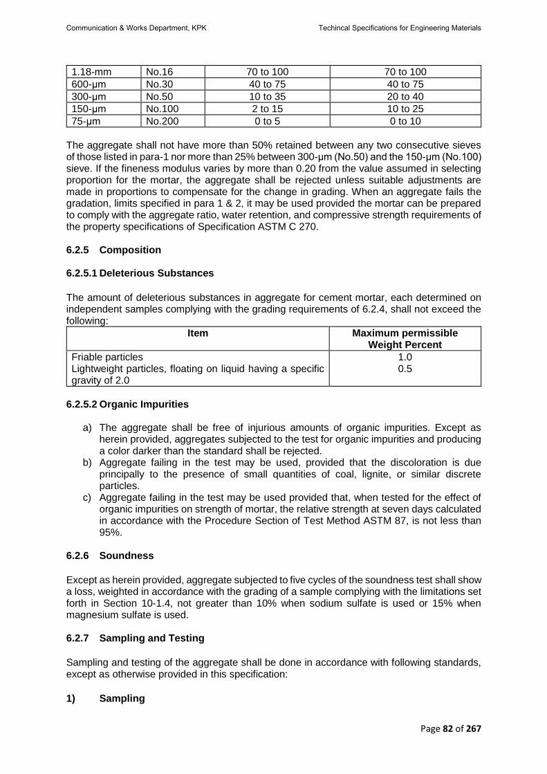
Page 82 of 267
1.18-mm No.16 70 to 100 70 to 100
600-μm No.30 40 to 75 40 to 75
300-μm No.50 10 to 35 20 to 40
150-μm No.100 2 to 15 10 to 25
75-μm No.200 0 to 5 0 to 10
The aggregate shall not have more than 50% retained between any two consecutive sieves of those listed in para-1 nor more than 25% between 300-μm (No.50) and the 150-μm (No.100) sieve. If the fineness modulus varies by more than 0.20 from the value assumed in selecting proportion for the mortar, the aggregate shall be rejected unless suitable adjustments are made in proportions to compensate for the change in grading. When an aggregate fails the gradation, limits specified in para 1 & 2, it may be used provided the mortar can be prepared to comply with the aggregate ratio, water retention, and compressive strength requirements of the property specifications of Specification ASTM C 270. 6.2.5 Composition 6.2.5.1 Deleterious Substances
The amount of deleterious substances in aggregate for cement mortar, each determined on independent samples complying with the grading requirements of 6.2.4, shall not exceed the following:
Item Maximum permissible Weight Percent
Friable particles Lightweight particles, floating on liquid having a specific gravity of 2.0
1.0 0.5
6.2.5.2 Organic Impurities
a) The aggregate shall be free of injurious amounts of organic impurities. Except as herein provided, aggregates subjected to the test for organic impurities and producing a color darker than the standard shall be rejected.
b) Aggregate failing in the test may be used, provided that the discoloration is due principally to the presence of small quantities of coal, lignite, or similar discrete particles.
c) Aggregate failing in the test may be used provided that, when tested for the effect of organic impurities on strength of mortar, the relative strength at seven days calculated in accordance with the Procedure Section of Test Method ASTM 87, is not less than 95%.
6.2.6 Soundness
Except as herein provided, aggregate subjected to five cycles of the soundness test shall show a loss, weighted in accordance with the grading of a sample complying with the limitations set forth in Section 10-1.4, not greater than 10% when sodium sulfate is used or 15% when magnesium sulfate is used. 6.2.7 Sampling and Testing
Sampling and testing of the aggregate shall be done in accordance with following standards, except as otherwise provided in this specification:
1) Sampling
Communication & Works Department, KPK Techincal Specifications for Engineering Materials
Page 83 of 267
Practice ASTM D 75 2) Sieve Analysis and Fineness Modulus Method ASTM C 136 3) Amount of Material Finer Than (75-Μm) No.200 Sieve Method ASTM C 117-95 4) Organic Impurities Test Method ASTMC C 40. 5) Effect of Organic Impurities on Strength Test Method ASTMC C 87. 6) Friable Particles Test Method ASTMC C 142. 7) Lightweight Constituents Test Method ASTMC C 123. 8) Soundness Test Method ASTMC C 88. 6.2.8 Storage
Aggregate for cement-sand mortar shall be stacked on a brick, wooden or other suitable platform so as to adequately protect it from dust and other admixtures. 6.2.9 Rate
The unit rate shall include furnishing aggregate as per specification, delivery and stacking at site of work. 6.2.10 Payment
Payment shall be made under:
Pay item Number
Description Unit
6.2.10.1 Supply of Aggregate for cement-sand mortar of specified quality.
Per 100 cubic feet.
Communication & Works Department, KPK Techincal Specifications for Engineering Materials

Page 84 of 267
6.3 Surkhi
6.3.1 Description
Surkhi is used as a substitute for sand in mortar and has almost the same function as sand. It also imparts some strength and hydraulicity. Surkhi is made by grinding burnt bricks, brick bats: or burnt clay to powder. Surkhi shall be first class, that is made by pounding or grinding fully burnt first class bricks or bats. Surkhi shall, on no consideration, be ground from over-burnt or under-burnt bricks and hits or from clay burnt by unapproved methods or obtained from kiln linings. 6.3.2 Quality and Storage
Surkhi shall be free from any admixture of clay, dust or foreign matter and shall be stacked a
brick, wooden or other suitable platform so as to be adequately protected from such
admixtures.
6.3.3 Fineness
Surkhi shall be of such fineness that it passes through a screen of 12 x 12 meshes to the
square inch, but does not pass one of 50 x 50 meshes to the square inch. For work that is to
remain permanently under water after construction the I2x12 mesh screen shall he replaced
by one of 8 X 8 meshes ton square inch.
6.3.4 Measurement
Surkhi shall be measured in bulk. The unit of measurement shall be one hundred cubic feet.
6.3.5 Rate
The unit rate shall include furnishing, grinding and screening Surkhi as per above specification
and delivery and stacking at Site of Work to be defined in the Conditions of Contract.
6.4 Fine Aggregate for Cement Concrete
6.4.1 Description
This specification defines the requirements of grading and quality of fine aggregate (other than lightweight or heavyweight aggregate) for use in concrete. 6.4.2 Source
Fine Aggregate shall be obtained from an approved source.
6.4.3 Methods of Test & Sampling
1. ASTM C 40 Test Method for Organic Impurities in fine aggregates for concrete. 2. ASTM C 87 Test Method for Effect of Organic Impurities in Fine Aggregate on Strength
of Mortar. 3. ASTM C 88 Test Method for Soundness of Aggregates by Use of Sodium Sulfate or
Magnesium Sulfate.
Communication & Works Department, KPK Techincal Specifications for Engineering Materials

Page 85 of 267
4. ASTM C 117 Test Method for Materials Finer than 75-μm (No.200 sieve) in Mineral Aggregates by Washing.
5. ASTM C 123 Test Method for Lightweight Pieces in Aggregate. 6. ASTM C 136 Test Method for Sieve Analysis of Fine and Coarse Aggregates. 7. ASTM C 142 Test Method for Clay Lumps and Friable Particles in Aggregates. 8. ASTM C 666 Test Method for Resistance of Concrete to Rapid Freezing and
Thawing’s. 9. ASTM D 75 Practice for Sampling Aggregates. 10. ASTM D 3665 Practice for Random Sampling of Construction Materials.
6.4.4 Grading
Fine Aggregate shall consist of well graded sand, stone screening or other inert material of
similar characteristics, or a combination of these. The whole of it shall pass through 3/16-inch
sieve and 2 to 10 per cent through sieve No. 100.
6.4.4.1 Sieve Analysis
a) Fine aggregate, except as provided in (b) and (c) shall be graded within the following
limits:
Sieve (Specification E 11) Percent Passing
9.5-mm 3/8-in. 100
4.75-mm No.4 95 to 100
2.36-mm No.8 80 to 100
1.18-mm No.16 50 to 85
600-μm No.30 25 to 60
300-μm No.50 5 to 30
150-μm No.100 0 to 10
b) The fine aggregate shall have not more than 45% passing any sieve and retained on
the next consecutive sieve of those shown in (a), and its fineness modulus shall not be less than 2.3 nor more than 3.1.
c) Fine aggregate failing to meet these grading requirements shall meet the requirements of this section provided that the supplier can demonstrate to the purchaser or specifier that concrete of the class specified, made with fine aggregate under consideration, will have relevant properties at least equal to those of concrete made with the same ingredients, with the exception that the reference fine aggregate shall be selected from a source having an acceptable performance record in similar concrete
Note: Fine aggregate that conforms to the grading requirements of a specification, prepared by another organization such as a state transportation agency, which is in general use in the area, should be considered as having a satisfactory service record with regard to those concrete properties affected by grading. 6.4.5 Deleterious Substances The amount of deleterious substances in fine aggregate shall not exceed the limits prescribed in specifications.
Communication & Works Department, KPK Techincal Specifications for Engineering Materials

Page 86 of 267
6.4.5.1 Organic Impurities
a) Fine aggregate shall be free of injurious amounts of organic impurities. Except as
herein provided, aggregates subjected to the test for organic impurities and producing a color darker than the standard shall be rejected.
b) Use of a fine aggregate failing in the test is not prohibited, provided that the discoloration is due principally to the presence of small quantities of coal, lignite, or similar discrete particles.
c) Use of fine a aggregate failing in the test is not prohibited, provided that, when tested for the effect of organic impurities on strength of mortar, the relative strength at 7-days, calculated in accordance with Test Method ASTM C 87, is not less than 95%.
Fine aggregate for use in concrete that will be subject to wetting, extended exposure to humid atmosphere, or contact with moist ground shall not contain any materials that are deleteriously reactive with the alkalies in the cement in an amount sufficient to cause excessive expansion of mortar or concrete, except that if such materials are present in injurious amounts, use of the fine aggregate is not prohibited when used with a cement containing less than 0.60% alkalis calculated as sodium oxide equivalent (Na2O+0.658K2O) or with the addition of a material that has been shown to prevent harmful expansion due to the alkali-aggregate reaction. 6.4.6 Soundness
a) Except as provided in b) and c), fine aggregate subjected to five cycles of the
soundness test shall have a weighted average loss not greater than 10% when sodium sulfate is used or 15% when magnesium sulfate is used.
b) Fine aggregate failing to meet the requirements of a) shall meet the requirements of this section provided that the supplier demonstrates to the purchaser or specifier that concrete of comparable properties, made from similar aggregate from the same source, has given satisfactory service when exposed to weathering similar to that to be encountered.
c) Fine aggregate not having a demonstrable service record and failing to meet the requirements of a) shall be regarded as meeting the requirements of this section provided that the supplier demonstrates to the purchaser or specifier it gives satisfactory results in concrete subjected to freezing and thawing test (see Test Method ASTM C 666).
6.4.7 Storage
Fine aggregate shall be stacked on a brick, wooden or other suitable platform so as to
adequately protect it from dust and other admixtures. Fine aggregate shall be measured in
bulk. The unit of the measurement shall be one hundred cubic feet.
6.4.8 Measurement The quantity of aggregate of shall be measured by volume. The unit of measurement shall be 100 cubic feet or cubic meter. 6.4.9 Rate and Payment The unit rate per unit of measurement shall be full compensation for furnishing and stockpiling all aggregates including all labour, equipment, tools and incidentals necessary to complete the work prescribed in this Section. Payment shall be made under:
Communication & Works Department, KPK Techincal Specifications for Engineering Materials

Page 87 of 267
Pay item Number Description Unit
6.4.9.1 Fine Aggregate Per 100 cubic feet.
Communication & Works Department, KPK Techincal Specifications for Engineering Materials
Page 88 of 267
6.5 Coarse Aggregate
6.5.1 Description This specification covers coarse aggregate, other than lightweight aggregate, for use in concrete. Coarse aggregate shall consist of gravel, crushed gravel, crushed stone, air-cooled blast furnace slage, conforming to the requirements of this specification. 6.5.2 Grading Coarse aggregates shall conform to the requirements prescribed in specifications for the size number specified. 6.5.3 Deleterious Substances
a) Except for the provision of c), the limits given in specifications shall apply for the class
of coarse aggregate designated in the purchase order or other document. If the class is not specified, the requirements for Class 3S, 3M, or 1N shall apply in the severe, moderate, and negligible weathering regions, respectively.
b) Coarse aggregate for use in concrete that will be subject to wetting, extended exposure to humid atmosphere, or contact with moist ground shall not contain any materials that are deleteriously reactive with the alkalies in the cement in an amount sufficient to cause excessive expansion of mortar or concrete except that if such materials are present in injurious amount, the coarse aggregate is not prohibited when used with sodium oxide equivalent (Na2O+0.658K2O) or with the addition of a material that has been shown to prevent harmful expansion due to the alkali-aggregate reaction.
c) Coarse aggregate having test results exceeding the limits specified in specifications shall be regarded as meeting the requirements of this section provided the supplier demonstrates to the purchaser or specifier that concrete made with similar aggregate from the same source has given satisfactory service in the absence of a demonstrable service record, provided that the aggregate produces concrete having satisfactory relevant properties.
6.5.4 Method of Sampling and Testing Sample and test the aggregates in accordance with the following methods, except as otherwise provided in this specification. Make the required tests on test specimens that comply with requirements of the designated test methods. It is not prohibited to use the same test specimen for sieve analysis and for determination of material finer than the 75-μm (No.200) sieve. The use of separated sizes from the sieve analysis is acceptable for soundness or abrasion tests, however, additional test specimen preparation is required. For other test procedures and the evaluation of potential alkali reactivity, when required, use independent test specimens. 1) Sampling ASTM Practice D 75 and Practice D 3665. 2) Grading and Fineness Modulus Test Method ASTM C 136. 3) Amount of Material Finer Than 75-Μm (No.200) Sieve Test Method ASTM C 117.
Communication & Works Department, KPK Techincal Specifications for Engineering Materials

Page 89 of 267
4) Organic Impurities Test Method ASTM C 40. 5) Effect 0f Organic Impurities on Strength Test Method ASTM C 87. 6) Soundness Test Method ASTM C 88. 7) Clay Lumps and Friable Particle Test Method ASTM C 142. 8) Coal and Lignite Test Method ASTM C 123, using a liquid of 2.0 specific gravity to remove the particles of coal and lignite. Only material that is brownish-black, or black, shall be considered coal or lignite. Coke shall not be classed as coal or lignite.
9) Bulk Density (Unit Weight) Of Slag Test Method ASTM C 29/C 29M. 10) Abrasion of Coarse Aggregate Test Method ASTM C 131 or Test Method ASTM C 535. 11) Freezing and Thawing Procedure for making freezing and thawing tests of concrete are described in Test Method ASTM C 666. 12) Chert Test Method ASTM C 123 is used to identify particles in a sample of coarse aggregate lighter than 2.40 specific gravity, and Guide C 295 to identify which of the particles in the light fraction are chert. 6.5.5 Storage
Coarse aggregate shall be stacked on a brick, wooden or other suitable platform so as to
adequately protect it from dust and other admixtures. Each type and size of aggregate shall
be stacked separately.
6.5.6 Measurement The quantity of aggregate of shall be measured by volume. The unit of measurement shall be 100 cubic feet or cubic meter.
Communication & Works Department, KPK Techincal Specifications for Engineering Materials

Page 90 of 267
6.5.7 Rate and Payment The unit rate per unit of measurement shall be full compensation for furnishing and stockpiling all aggregates including all labour, equipment, tools and incidentals necessary to complete the work prescribed in this Section. Payment shall be made under:
Pay item Number
Description Unit
6.5.7.1 Supply of Coarse Aggregate for cement concrete of specified quality.
Per 100 cubic feet.
Communication & Works Department, KPK Techincal Specifications for Engineering Materials

Page 91 of 267
6.6 Cinders
6.6.1 Description Cinders are produced as waste materials from steam boilers using bituminous coal. They are hard, vitreous., granular, porous and light in weight. Cinders weigh about 45 lbs. per cubic foot. They are used in buildings for floor and roof construction where there is no wetting and drying or freezing and thawing. They are commonly used in making a lightweight concrete building block. The cost is low since they are a waste material and may usually be bad for the hauling. Cinder shall be obtained from an approved source. Only clean furnace clinker of coat, i. e. residue from furnaces of steam boilers, etc., using coal fuel only shall be used and any admixture of wood ash shall cause the whole of the cinder to be rejected. Cinder produced from coal containing an excessive amount of Sulphur or other injurious chemicals shall not be used at all. 6.6.2 Quality and Storage Cinder shall be free from any admixture of clay, dust, vegetation, or any foreign matter and
shall be stacked on brick, wooden 01 other suitable platform so as to be adequately protected
from such admixtures.
6.6.3 Fineness
Cinders shall be ground in mile and screened so that the whole of it shall pass through a
screen of 12x 12 meshes to the square inch but does, not pass one of 50x 50 meshes to the
square inch.
6.6.4 Use
Cinder shall be used as a substitute for sand or Surkhi only when it is specified or allowed by
the Engineer-in-charge.
6.6.5 Measurement
The quantity of aggregate of shall be measured by volume. The unit of measurement shall be 100 cubic feet or cubic meter. 6.6.6 Rate and Payment The unit rate per unit of measurement shall be full compensation for furnishing and stockpiling all aggregates including all labour, equipment, tools and incidentals necessary to complete the work prescribed in this Section. Payment shall be made under:
Pay item Number
Description Unit
6.6.6.1 Supply of Cinder of specified quality. Per 100 cubic feet.
Communication & Works Department, KPK Techincal Specifications for Engineering Materials

Page 92 of 267
6.7 Brick Ballast
6.7.1 Description
The work covered in this section consists of supplying coarse aggregate which shall consist of brick ballast having clean, hard, tough durable pieces free from injurious amounts of soft, friable, thin, elongated, or laminated pieces, soluble salts, organic or other deleterious matter. 6.7.2 Source Brick ballast shall be made from 1st class or over burnt bricks. 6.7.3 Grading
It shall be uniformly graded from coarse to fine within the limits specified in specifications. 6.7.4 Quality
Unless otherwise specified elsewhere it shall conform to the following requirement:
i. Percentage wear by Los Angeles Not more than 45 Abrasion test at 500 Revolutions (AASHO-T-96).
ii. Soundness of Aggregate by Not more than 5 freezing and thawing (AASHTO-T-103) Max. percentage loss on 15 cycles.
iii. Soundness of Aggregate by use of Sodium Not more than 8 Sulphate or Magnesium Sulphate (AASHTO-T-104) Max. percentage loss on 5 cycles.
6.7.5 Impurities The deleterious matter in brick ballast shall not exceed the following: Clay Lumps 0.25%
Grade 3” 2” 1 ½” 1” ¾” ½” 3/8” No. 4 No. 10
No. 16
3 100 97-100
97-100
40-75 0-5
5 100 95-100
85-100
60-90 30-60 0-6
6 100 97-100
75-95 0-5
8 100 97-100
60-90 40-65 20-45 6-22 0-6
9 100 95-100
75-100
35-70 5-30 0-7
10 100 60-85 30-60 10-35 0-5
11 95-100
0-30 0-6
12 100 95-100
30-65 0-15
Communication & Works Department, KPK Techincal Specifications for Engineering Materials

Page 93 of 267
13 100 90-100
0-10 0-2
16 100 80-100
35-60
0-10 0-5
The above gradations represent the extreme limits for the various sizes indicated, which will be used in determining the suitability for use of coarse aggregate from all sources of supply. For any grade from any one source, the gradation shall be held reasonably uniform and not subject to the extreme percentage of gradation specified above. 6.7.6 Stocking Aggregate The stockpile sites, as staked by the Engineer, shall be prepared by clearing, burning of all trees, stumps, bush and debris. The floor for each stockpile shall be comparatively uniform in cross section. The completed stockpiles shall be neat and regular in form shall be made to occupy the smallest feasible areas. Only when ordered by the Engineer shall the height of the piles or their average depth be more than 6 feet. The side slopes shall not be flatter than 1½:1. To avoid segregation of the various sizes in each stockpile, the aggregate shall be deposited in uniform layer or lifts not exceeding 1 foot in thickness. The aggregate shall be placed in each lift by trucks or other types of hauling units. Stockpiling from a conveyor belt will not be permitted. The piles shall be so located and so constructed that no intermingling of grading will occur. 6.7.7 Measurement It shall be measured in bulk. The unit of measurement shall be one hundred cubic feet. 6.7.8 Rate and Payment
The unit rate shall be full compensation for furnishing brick ballast in well graded and clear state as per above specification at site of work, including loading, transportation, unloading and stacking at site of work to be defined in the bid schedule. Payment shall be made under:
Pay item Number
Description Unit
6.7.8.1 Supply of Brick Ballast of specified Gradation. Per 100 cubic feet.
Communication & Works Department, KPK Techincal Specifications for Engineering Materials

Page 94 of 267
CHAPTER – 7 STONE
7.1 General
7.1.1 Stone as a Building Material Stone is a high-class building material, and where permanency of structure is required, it
continues to enjoy superiority over bricks and all other rival materials. It has satisfactorily stood
the test of time. When properly selected, it weathers well and does not involve heavy
maintenance costs. These qualities have always been the deciding factors in its favor for use
in permanent engineering work.
7.1.2 Geological Classification
Hocks are classified according to their geological formation in the following three groups: —
1) Igneous Rocks Igneous rocks are formed by the rapid cooling of the molten material from inside the earth and
are volcanic in their origin. These rocks are generally strong and durable. Granite and Traps
belong to this group.
2) Sedimentary Rocks
Sedimentary rocks or aqueous rocks are formed by the consolidation of particles of decayed
rocks which have been deposited by streams of water. Limestone and sandstone are typical
examples of such rocks.
3) Metamorphic Rocks Metamorphic rocks are either igneous or sedimentary rocks which have undergone structural changes m the form and colour due to intense pressure or heat, or both. These rocks are hard and durable. Slates, marbles and schist are examples of metamorphic rocks. 7.1.3 Scientific Classification of Stone
Building stones arc classified under the following categories, depending upon their
composition
1) Siliceous Stone
Its base or principal constituent is silica, e. g. sandstone, trap, granite, etc.
2) Argillaceous Stone Its base is clay, e. g. laterite, slate, etc.
3) Calcareous Stone Its base is lime or carbonate of calcium, i.e., limestone, marble, etc.
Communication & Works Department, KPK Techincal Specifications for Engineering Materials

Page 95 of 267
7.1.4 Source
Stone is obtained from rock by means of quarrying. The term quarrying is generally applied to
the art of extracting stone of various types for general building works, etc. The area where the
extraction takes place is termed as quarry.
7.1.5 Location of Quarry
The exact location of quarry is done after carrying out sonic exploratory work to have an idea
of the underlying rock and the over burden to be removed to reach it. The following factors
usually determine the location of the quarry.
a) Availability of the desired building stone at or near the surface of the ground.
b) Proximity of the quarry to the existing communication lines.
c) The possibility of arranging the drainage for quarry pit at a very low cost.
d) Availability of suitable sites for the location of power station, stone crusher and stone
dressing and cutting machinery, etc.
7.1.6 Methods of Quarrying
The method of quarrying depends on the structure and nature of the rock and the purposes
for which the stone is intended to be used. There are two principal methods of quarrying in
use; namely, quarrying by hard tools and quarrying by blasting.
7.1.6.1 Quarrying by hard Tools
Quarrying by bard tools, such as crow-bars, jumper, pick-axes, feathers and wedges is
generally employed for quarrying in soft rocks, stratified-and cleavable types and in beds of
shingle deposits.
7.1.6.2 Quarrying by Machine Quarrying by Machine When the quarrying is carried out on a large scale the following
mechanical means are employed: —
1) Channeling
Channeling machines consist essentially of reciprocating saws or drills so operated as to cut
grooves of any desired depth, and up to a maximum of 40 feet length. The machine is capable
of moving on the rock surface. For softer stone, saws arc used to cut large blocks from the
rock mass.
2) Cutting
The culling of stone is done with the aid of either circular saws or reciprocating saws and the
stone block is mounted on trolley which brings the stone before the-saw machine. The use of
abrasives is very important in cutting a stone. Machinery is also used for plaining and,
polishing the finished surface of stone blocks and paving sets.
Communication & Works Department, KPK Techincal Specifications for Engineering Materials

Page 96 of 267
3) Breaking
Breaking the cut pieces and quarry spoils into road metal concrete aggregate or railway
ballasts is done by means of a jaw crusher, a gyratory crusher or impact crushing machine.
To have effective crushing some form of automatic feed device is also installed. Sometimes
two stage crushing gives better results. Subsequent to crushing, materials are screened and
sorted out according to grades or sizes. Screen can be fixed, movable or rotary type.
4) Lifting
For lifting large blocks, for handling and cutting and transportation bf the material from the
quarry, crane and derrick pool used are conveniently mounted on trollies or wagon. v. Drilling.
Holes arc drilled in rock by rotary type or percussion type power drills. Deep holes require
impact drilling machines.
7.1.6.3 Quarrying with Blasting
The quarrying of hard and compact stone is carried out with the use of explosives in a
systematic manner. The aim of blasting is to loosen and lo separate ns much rock as possible
out of the rock muss and not lo shutter the rock into pieces. Blasting is also adopted to reduce
the larger boulders into smaller ones which are more convenient and handier Sized. This is
usually termed as secondary blasting. The various singes involved in the method of quarrying
by blasting are given below: —
1) Boring holes into the rock
Great skill and experience are required for the location of the exact spots in the rock mass
where the intended explosion should take place to produce the desired effects. Such spots
having been located, holes are bored by hand tools consisting or hammer and a short iron rod
with a chiseled edge. The size of the holes usually varies from# in. to U ins. diameter. When
stones are required in large quantities hand drilling may be replaced by machine drilling. Use
of water is made to facilitate drilling operations. The rock powder and mud created during
drilling are removed by a scraper or a spoon or by a blast of compressed air.
2) Charging with explosives
The next operation is to charge the hole with an explosive. Before filling the explosives, it is
quite essential that the hole should be thoroughly dry. There are several varieties of explosives
used for the purpose, like blasting powder or gunpowder dynamite or nitro-glycerin, gun cotton
or nitrocellulose, cordite.
3) Blasting powdery gunpowder.
It consists of 70 to 75 psi is by weight of saltpeter (KNO3) and 15 parts of charcoal with 10 to
15 parts of Sulphur, and generates the desired explosives force. This is considered to be a
weak explosive and loosens fairly large blocks in soli stones.
Communication & Works Department, KPK Techincal Specifications for Engineering Materials

Page 97 of 267
4) Dynamite or Nitro-glycerin
It has a high explosive value and is available in the form of cartridges. Its cartridge form makes
it especially suitable for use under wet conditions and heavy work.
5) Gun Cotton or Nitrocellulose
It is much more powerful than dynamite and great care has to be taken in storing and using it.
6) Cordite
It is the most commonly employed form of explosive. It is readily available in the form of
cartridges and sticks. It is slow burning but stronger and more economical than dynamite or
blasting powder. It is also suitable for use tinder water. In modern practice, however, liquid
oxygen is preferred to all other explosives.
7) Tamping
Tamping is necessary to prevent the reaction of the explosives along the blasting hole itself.
When the explosive is being put into the hole and before the tamping is a fuse of sufficient
length is inserted. Tamping consists of filling up the hole with specially prepared stiff sandy
clay which is tamped each time a little quantity is put into a small depth in the hole. A brass
rod called the tamping bar is used for the purpose of tamping. Tamping has to be done very
carefully and at the same time very skillfully to render the explosive very effective. Sometimes
a priming needle of about 1/16 in. diameter is inserted in the tamping material which is
removed after the tamping is over. The fuse is then introduced to admit of the explosive being
fired. Sometimes a small quantity of gunpowder is poured into the hole to connect the
explosive to the end of the fuse at the top.
8) Firing The fuse is kept of a sufficient length to allow the person firing it enough time to retreat to a
safe distance before the explosion of the charge takes place. Two or more holes or groups of
holes may be connected with a common fuse for firing simultaneously. The number of holes
fired each time should be recorded to make sure later if any charge has failed to explode. A
dull sound of a muffled character indicates the liberation of a large mass of stone from the
parent rock. Electrically operated firing devices are also adopted to create the spark needed
for the explosion. This is a safe method and a number of explosions can be controlled from
one place in a series. Detonators are commonly used for this purpose.
9) Secondary Blasting When large blocks of stones arc liberated from the initial blasting Operation, they are again
broken to smaller pieces by a secondary Wasting operation,
7.1.6.3.1 Directions for Blasting The following directions for blasting with dynamite and high explosives should be followed:
Communication & Works Department, KPK Techincal Specifications for Engineering Materials
Page 98 of 267
a) Blasting operations must be carried out under the supervisions of a competent person during fixed hour of the day, preferably during the mid-day luncheon hour or at the close of the working day.
b) Danger Bags should be prominently displayed and all the people except those who have actually to light the fuses must be removed to a safe distance of not less than 200 yards.
c) All fuses must be cut to the lengths required before being inserted into the holes. d) The number of charges to be fired and the actual number of shots heard mast be
compared and the quarryman in charge, most satisfy himself by examination that all charges have exploded before quarryman are permitted to approach the-scene. Under no circumstances is the withdrawal of an unexploded charge to be permitted; the tamping and Charges should be flooded with water and the hole marked in a distinguishing manner. Another hole-should be jumped at a distance of about 18 inches from the old hook and fired in the usual way. The results should be carefully examined by the quarryman in charge and the operation continued until the original charge is exploded.
e) For making the hole in an explosive cartridge to take detonator, only hardwood should be used and only wooden tempers should be used for tampering explosive charge. On no account should any metal implements be used.
f) After firing an explosive charge sufficient time must be allowed to elapse before men are allowed to return to work within the danger zone: otherwise asphyxiation from carbon monoxide fumes may occur.
g) Some explosives are very dangerous in frosty weather. If work cannot he suspended during frosty weather special precautions must be taken to keep the explosive cartridges at a Sale temperature.
h) When cartridges sweat these should not be handled with hare hands. 7.1.6.3.2 Mis Fires
Mis-fires are sources of great danger. If it is suspected that a port of the blast has failed to fire
or is delayed allow sufficient time to pass before entering the danger zone. When fuse and
blasting caps ore used, a sale time (at leak an hour) should be allowed. The quarryman-in-
charge should at once report to this next superior all cases of mis-fire, the cause of the same
and the step taken by him in connection therewith.
7.1.6.3.3 Precautions against Mis Fires
The following precaution should be taken against mis-fires.
a) The safety fuse (lighting end) should be cut obliquely with a knife.
b) All sawdust must be cleaned out of the detonator; this can be done by blowing down the detonator and tapping the open end. No instrument must be inserted into the detonator for this purpose.
c) After inserting the fuse in the detonator, it should be fixed by means of the nippers.
d) If there is water present, or if the borehole is damp, the junction of the fuse and the detonator must be made watertight by means of tough grease, white lead or tar.
e) The detonator should be inserted into the cartridge so that about one-third of the copper tube is Ica exposed outside the explosive. The safety fuse outside the detonator should be securely tied in position in the cartridge. Waterproof fuse only should be-used in damp boreholes or when water is present in the borehole.
f) If a mis-fire has been found due to the defective fuse, detonator or dynamite, the whole quantity or box from which the defective article was taken must be returned to the office for inspection.
Communication & Works Department, KPK Techincal Specifications for Engineering Materials

Page 99 of 267
7.1.6.3.4 Storage of Explosives A special magazine for the storage of explosives should be constricted and the following rules
observed there:
a. The magazine should at all times be kept scrupulously clean. High explosives, like dynamite, should be stored in a dry, clean, well-ventilated bullet proof and fireproof building on an isolated site, at least 150 ft away from any other building or thoroughfare and a quartet of a mile away from any working kiln or furnace.
b. No unauthorized person is at any lime to be admitted into the magazine. c. The person in charge of the magazine is to take care that the magazine is well and
securely locked. d. The magazine is on no account to be opened during, or on the approach of, a
thunderstorm, and no person should remain in the vicinity of the magazine during such a storm.
e. Magazine shoes without nails should be kept at all times in the magazine, and a wooden tub or cement trough about one' foot high and 18 in diameter, filled with water should be fixed near the door of the magazine.
f. Persons entering the magazine must put on the magazine shoes provided for the purpose and be careful:
i. not to put their foot on the clean floor unless they have the magazine shoes on;
ii. not to allow the magazine shoe to touch the ground outside the clean floor; and
iii. not to allow any dirt or grit to fall on the clean floor. iv. Persons with bare feet will before entering the magazine dip their feet in
water and then step directly from the tub over the barrier (if there is one) onto the clean floor.
v. A brush or broom should be kept in the lobby of the magazine for clearing out the magazine on each occasion it is opened, for the receipt, delivery or inspection of explosives.
vi. No matches or inflammable materials should be allowed inside the magazine. Light should be obtained from 'an electric storage battery lantern.
vii. No person having articles of steel or iron on him is to be allowed to enter the magazine.
viii. Oily cotton rags waste, and articles liable to spontaneous ignition should not be taken into the magazine.
ix. Workmen or menials should be examined before they enter the magazine to sec that they have none of the articles mentioned in rules (Ix), (x) and (xi) on their person. All other persons shall have no such articles on their person.
x. No tools or implements other than those of copper, brass, gunmetal or wood should he allowed inside the magazine. Tools should he used only with great gentleness and care.
xi. Boxes of explosives should not be thrown clown or dragged along the floor and should be stacked on wooden trestles. Where there are white ants, the legs of the trestles should rest in shallow copper lead or brass howls containing water. In hot countries open boxes or dynamite should never be exposed to the direct rays of the sun,
xii. Empty boxes should not be kept in the magazine, nor should any loose packing materials be about.
Communication & Works Department, KPK Techincal Specifications for Engineering Materials
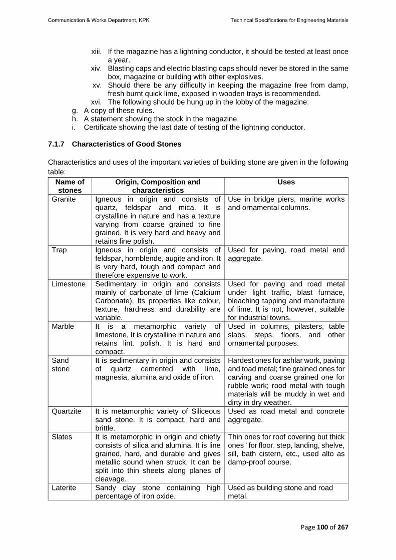
Page 100 of 267
xiii. If the magazine has a lightning conductor, it should be tested at least once a year.
xiv. Blasting caps and electric blasting caps should never be stored in the same box, magazine or building with other explosives.
xv. Should there be any difficulty in keeping the magazine free from damp, fresh burnt quick lime, exposed in wooden trays is recommended.
xvi. The following should be hung up in the lobby of the magazine: g. A copy of these rules. h. A statement showing the stock in the magazine. i. Certificate showing the last date of testing of the lightning conductor.
7.1.7 Characteristics of Good Stones
Characteristics and uses of the important varieties of building stone are given in the following
table:
Name of stones
Origin, Composition and characteristics
Uses
Granite Igneous in origin and consists of quartz, feldspar and mica. It is crystalline in nature and has a texture varying from coarse grained to fine grained. It is very hard and heavy and retains fine polish.
Use in bridge piers, marine works and ornamental columns.
Trap Igneous in origin and consists of feldspar, hornblende, augite and iron. It is very hard, tough and compact and therefore expensive to work.
Used for paving, road metal and aggregate.
Limestone Sedimentary in origin and consists mainly of carbonate of lime (Calcium Carbonate), Its properties like colour, texture, hardness and durability are variable.
Used for paving and road metal under light traffic, blast furnace, bleaching tapping and manufacture of lime. It is not, however, suitable for industrial towns.
Marble It is a metamorphic variety of limestone, It is crystalline in nature and retains lint. polish. It is hard and compact.
Used in columns, pilasters, table slabs, steps, floors, and other ornamental purposes.
Sand stone
It is sedimentary in origin and consists of quartz cemented with lime, magnesia, alumina and oxide of iron.
Hardest ones for ashlar work, paving and toad metal; fine grained ones for carving and coarse grained one for rubble work; rood metal with tough materials will be muddy in wet and dirty in dry weather.
Quartzite It is metamorphic variety of Siliceous sand stone. It is compact, hard and brittle.
Used as road metal and concrete aggregate.
Slates It is metamorphic in origin and chiefly consists of silica and alumina. It is line grained, hard, and durable and gives metallic sound when struck. It can be split into thin sheets along planes of cleavage.
Thin ones for roof covering but thick ones ' for floor. step, landing, shelve, sill, bath cistern, etc., used alto as damp-proof course.
Laterite Sandy clay stone containing high percentage of iron oxide.
Used as building stone and road metal.
Communication & Works Department, KPK Techincal Specifications for Engineering Materials

Page 101 of 267
7.1.8 Data for Building Stones of Good Quality
Kin
d o
f S
ton
e
We
igh
t p
ou
nd
s
per
cu
.ft.
Co
mp
ress
ive
Str
en
gth
Sh
ea
rin
g
Str
en
gth
Mo
du
lus o
f
Ru
ptu
re
p.s
.i
Mo
du
lus o
f
ela
sti
cit
y P
.S.J
Co
eft
. o
f.
exp
en
sio
n p
er
deg
.F.
Ab
so
rpti
on
of
wa
ter
perc
en
t
of
we
igh
t o
f
sto
ne
Granite range Average
160-170 165
15000-26000 20200
1800-2800 2300
1200-2200 1600
5.0-9.8 7.5
_ 0.40
_ 0.5
Sandstone range Average
135-150 140
6700-19000 12500
1200-2500 1700
500-2200 1500
1.00-7.70 3.30
0.55
5.0
Limestone range Average
140-180 160
3200-20000 9000
1000-2200 1400
250-2700 1200
4.00-14.70 8.40
0.45
7.7
Marble range Average
160-180 170
10300-16100 12600
1000-1600 1300
850-2300 1500
4.00-12.60 8.20
0.45
0.4
Slate range Average
170-180 175
14000-3000 15000
- -
7000-11000 8500
13.90-16.20 14.00
0.58 0.5
Trap Average
185 20000 - - - - -
7.1.9 Methods of Preserving Stone
Stone must be protected against deterioration to prolong the life of the structure and to stop
the lilac work from becoming unsightly. The most common methods are:
a. Painting, and
b. Plastering
Various paints, oil and chemical solutions can be, applied to protect. stone from deterioration.
These treatments-have to be renewed periodically, say after every 5 to 10 years. The more
successful of such methods, of treatment have been the application of boiled linseed oil,
paraffin, soap and alum solutions, silicate of lime or Ransom’s process. Before the application
of any of these treatments, the surface must be brushed, cleaned and made completely dry.
Boiled linseed oil is brushed on in one or two coals followed by a coat or dilute ammonia in
warm water. The latter application unities the discolouration produced by the oil. Melted
paraffin may be applied by brush and then forced into the pores of the stone by heating the
surface to a temperature of about 60°C. Sometimes paraffin is mixed with a solution or
creosote and naphtha to prevent organic growth on the stone. Ransom’s process consists of
filling potassium or sodium chloride into the' pores of the stone by repeated applications or the
solution by brush. After completely drying the surface, a coat of calcium chloride is applied,
which produces a strong lime silicate cement which is not soluble in water. The use of paint is
not recommended »s U never gives the desired shade of the stone and - has to be renewed
quite frequently, which makes it a costly treatment. In spite of the high preservative qualities
of coal tar or bitumen, their black colour does not permit of their use on face work. In
atmospheres charged with Sulphurous or carbonic acids, the use of a solution of barium
Communication & Works Department, KPK Techincal Specifications for Engineering Materials

Page 102 of 267
hydrate BaCh" known as "Baryta" is helpful 'when applied in three coats on stones where the
cause of decay is the formation of-crystals of calcium sulphates. The formations of barium
sulphate on the surface due to the application of "Baryta" give an insoluble surface to the
stone, which is not affected by the atmosphere. "Szerelmeys" Stone Liquid" consists of silicate
of sodium or potassium in combination with chloride of calcium and barium and is applied in
two or three coats. Before applying the liquid, generally a preliminary coat-of some bituminous
liquid is given. None of these methods is cheap enough to make the use of the preservatives
possible in ordinary buildings. Also, under the normal climatically conditions prevailing in West
Pakistan, preservation of stone is generally not required.
Communication & Works Department, KPK Techincal Specifications for Engineering Materials

Page 103 of 267
7.2 Stone for Masonry
7.2.1 Description This specification covers stone intended for use in stone masonry work. 7.2.2 Physical Properties
Stone shall be hard, tough, compact, durable having uniform colour and free from faults and cleavage. Stone for Ashlers masonry shall be free of seams, laminations and minerals which by weathering would cause decoloration or deterioration stone should conform to the following standards:
a. Unit weight 140 lbs./cft. (Min.) b. Compressive strength 12500 psi (Min.) c. Modulus of rupture 1200 psi (Min.) d. Water absorption 7.7% (Max.) per wt. of stone.
7.2.3 Sampling & Test Method
a. ASTM – C-97 Test Methods for Absorption and Bulk specific gravity (unit weight) of dimension stone.
b. ASTM – C-170 Test Method for Compressive Strength of Dimension Stone. c. ASTM – C-99 Test Method for Modulus of Rupture of Dimension Stone.
7.2.4 Size and Shape
Each stone shall be free from depressions and projections that might weaken it or prevent it from being properly bedded, and shall be of such shape as will meet both architecturally and structurally the requirements for the class of masonry specified. In general stones shall have thickness of not less than 125mm (5") width of not less than 1½" time their respective widths. Where headers are required their lengths shall be not less than the width of the widest adjacent stretches plus 300mm (12"). At least 50 percent of the total volume of the masonry shall be of stone having a volume of at least 0.03cu.m. (1-cu.ft.). 7.2.5 Dressing and Cutting
The stone shall be dressed to remove any thin or weak portions. All visible edges shall be free from chipping. Face stones shall be dressed to provide bed and joint lines with a maximum variation from true lines as follows:
a. Random rubble masonry (1½") b. Course rubble masonry (2nd Class) (¾") c. Course rubble masonry (1st Class) (1/4") d. Ashlars masonry (1/16")
7.2.6 Bed Surfaces Bed surface of face stones shall be normal to the faces of the stone for about 75mm (3") and this point may depart from normal not be exceed 25mm (25mm (1") in 300mm (12") for ashlar masonry and 50mm (2") in 300mm (12"), for all other classes. 7.2.7 Joint Surfaces
Communication & Works Department, KPK Techincal Specifications for Engineering Materials

Page 104 of 267
In all classes except ashlar masonry, the joint surfaces for face stone shall form an angle with the bed surface of not less than 45 degree. In ashlar masonry, the joint surface shall be normal to the bed surfaces. They shall also be normal to the exposed faces of the stone for at least 50mm (2"), from which point they may depart from normal not be exceed 25mm (1") in 300mm (12"). The corners at the meeting of the bed and joint lines shall not be rounded in excess of 38mm (1½") in case of Random rubble masonry. Course rubble masonry & Ashlar masonry shall have no rounding. 7.2.8 Bedding
Rubble stone shall be evenly bedded and shall be quarried in as large blocks as will permit of
being handled. No stone shall measure less than one-third, of a cubic foot.
7.2.9 Stacking
Stacking stone should be done on even ground. The length and breadth of the stack shall be
in multiples of 10 and the height may vary from 2 ft. to 5 ft.
7.2.10 Measurement
Stone shall be measured in bulk; the unit of measurement shall be one hundred cubic feet.
Actual stone contents shall he obtained by, multiplying the stack measurement with a factor
of 0.75.
7.2.11 Rate The unit rate shall be full compensation for furnishing stone for a particular class of masonry conforming to the stone specifications and attacking at site of work including quarrying, dressing, loading, transportation and unloading etc. complete in all respects. 7.2.12 Payment
Payment shall be made under:
Pay item Number
Description Unit
7.2.12.1 Supply of Stone for Random Rubble Masonry of specified quality.
Per 100 cubic feet.
7.2.12.2 Supply of Stone for Course Rubble Masonry (1st Class) of specified quality.
Per 100 cubic feet.
7.2.12.3 Supply of Stone for Course Rubble Masonry (2nd Class) of specified quality.
Per 100 cubic feet.
7.2.12.4 Supply of Stone for Ashlar of specified quality. Per 100 cubic feet.
7.3 Stone Metal for Road Work
a. Stone metal shall be procured from an approved source.
b. Stone metal shall be broken from hard durable tough sync of uniform texture. Only tot
stone available at the quarry shall be used. Where metal has been broken from water-
borne boulders, no individual boulder shall weigh less than 8 lbs.
Communication & Works Department, KPK Techincal Specifications for Engineering Materials

Page 105 of 267
7.3.1 Gauge Stone shall be broken in the gauge specified. The broken Witt shall have sharp edges and clean fractured faces. 7.3.2 2.5” Gauge Stone metal of 2 1/2” inches gauge shall pass a 2" internal diameter ring in one direction and
on dimension or any stone shall be greater than 3.
7.3.3 1.5” Gauge Stone metal of 1/4 inches gauge shall all pass through a ring of 1 % internal diameter in one & reaction and no dimension of any stone shall exceed 2" in length. 7.3.4 Sifting Stone metal, when sifted through a screen -made of ¼” diameter bar spaced 3/4 centre to
centre, shall yield not less than 5% and not more than 10% by volume of fine material or "bajri",
Where required, the contractor shall so sift the stone, stacking the fine material and the metal
separated.
7.3.5 Supply Included in Rate but not Screening Unless otherwise specified the cost of this sifting or screening is not include in the rate in
supply of stone metal and shall be paid for separately as screening. The supply of fine material
however, included in the rate and this material will not be paid for in addition to the metal.
7.3.6 Stockings Metal shall be stacked at roadside clear of formation width in continuous stacks leaving in
such gaps for drainage as are ordered by the Engineer-in-charge. The stacks shall be made
on the ground and shall be to the template supplied by the Engineer-in-charge. Where metal
has stacked to such template, the Engineer-in-charge shall have the option of selecting one
length of in each furlong and getting it restocked in his presence and basing his
measurements, for the entire mi; on the average of the results obtained from such restacking.
Stacking shall be commenced at the farthest from the source of supply and shall proceed
continuously. Stacks shall be normally 30 feet from the centre line of the road and parallel to
it.
7.3.7 Measurements
The measurement stone metal shall be by volume. The unit of measurement shall) one
hundred cubic feet.
7.3.8 Rate
The unit rate shall include the cost of stone metal conforming to the above spite delivery and
stacking at Site of Work to be donned in the Conditions of the Contract.
Communication & Works Department, KPK Techincal Specifications for Engineering Materials

Page 106 of 267
7.4 Cast Stone
7.4.1 Description
Any material manufactured with aggregate and cementitious binder and intended to resemble in appearance, and be used in a similar way to, natural stone. Cast stone is either homogeneous throughout or consists of a facing material and backing concrete. 7.4.2 Materials 1) Binders and Binder Constituents Cast stone shall be made using one of the following binders complying with the appropriate standard:
a. Ordinary and Rapid-hardening Portland Cement. It shall conform to chapter 3 of these specifications Type-III
b. Portland Blast Furnace Cement. It shall conform to chapter 3 of these specifications Type-II
c. Sulphate Resisting Portland Cement. It shall conform to chapter 3 of these specifications Type-V
2) Aggregates
a. Natural Fine Aggregates It shall conform 6.4 of these specifications.
b. Natural Coarse Aggregates It shall conform to 6.5 of these specifications. 7.4.3 Two Parts Mixes
When cast stone is made from separate facing and backing mixes: a. the facing shall have a minimum thickness of 20mm at any point; b. a bond between the facing ad backing mixes shall be made either by a mechanical
key or by inter-diffusion. 7.4.4 Dimensional Deviations and Slenderness Ratio
The maximum dimensional deviations from the stated work size lengths and widths shall be as follows: up to and including 2m +0 mm
-5mm above 2m +0mm
-10mm The minimum mean thickness of any section shall be as follows: Maximum length Minimum mean thickness up to 1.0m 50mm 1.0 to 1.5m 90mm above 1.5m 120mm Note. For ribbed units the dimensions should be agreed between the purchaser and the supplier.
Communication & Works Department, KPK Techincal Specifications for Engineering Materials

Page 107 of 267
7.4.5 Surface Finish
The colour and texture of the exposed face of cast stone shall be agreed between supplier, manufacture and Engineer-in-charge. The supplier should on request supply a sample of representative size for the approval of the Engineer-in-charge. 7.4.6 Compressive Strength
Either the average crushing strength of three cubes sampled and tested shall be not less than 25 N/mm2 (3625 Psi) or the average rebound of specimens sampled and tested shall be not less than 25%. 7.4.7 Drying Shrinkage When tested as described in British Standard BS 1217:1975 Appendix B and adopting the sampling procedure described in 11-3.9, the following maximum limits shall apply: a) The homogeneous units or to facing concretes: 0.04% b) The difference between the averages of the shrinkages of facing and backing concretes: 0.02% 7.4.8 Initial Surface Absorption
Grade A: < 0.25 mL/ (m2. s) at 10 min and
< 0.10 mL/ (m2. s) at 1 h. Grade B: 0.25 mL/ (m2. s) to 0.50 mL/ (m2. s) and
< 0.10 mL/ (m2. s) to 0.2mL/ (m2. s) at 1 h. 7.4.9 Sampling 7.4.9.1 General
The purchaser (or his representative) may select at random from each consignment of 250 units (or part thereof) any three units suitable for carrying out the tests required. 7.4.9.2 Sampling for Compressive Strength Test
When strength testing in accordance with British Standard BS 1217:1975 Appendix A No.A.2 is specified, three cubes of 100mm size shall be made from the facing and three more cubes from the backing mix where applicable, with compaction as used in making the unit. Three (or six) cubes shall be made for each consignment of 250 units (or part thereof). 7.4.9.3 Sampling for Drying Shrinkage Test 1) Homogeneous Saw one specimen from each of the three units measuring 75+5mm x 75+5mm x 215+15mm and fix surface strain gauge points to the weathering face with a gauge length of 200+10mm according to British Standard BS 2028:1968 Appendix E. 2) Facing and Backing Mixes Use either a whole unit or saw one prism 75+5mm x 215+15mm x the complete thickness from each of the three units and fix on to the weathering and opposite faces surface strain gauge reference points with a gauge length of 200+10mm.
Communication & Works Department, KPK Techincal Specifications for Engineering Materials

Page 108 of 267
7.4.9.4 Cube Crushing Test For each consignment three cubes of 100mm size shall be made from the facing mix and three more cubes from the backing mix, where applicable. Cubes shall be compacted in the same way as the finished cast stone. 7.4.10 Testing 1. Determination of Compressive Strength In accordance with Appendix A of
BS1217. 2. Determination of Drying Shrinkage In accordance with Appendix B of
BS1217. 3. Determination of Initial Surface In accordance with Absorption Appendix
C of BS1217. 7.4.11 Marking
The following particulars shall be clearly marked on the delivery note, drawing, invoice or supplier’s certificate supplied with a consignment of cast stone products:
a) the name, trade mark or other means of identification of the manufacturer; b) whether the product is homogeneous or two-part; c) the grade of surface absorption, i.e. A or B.
7.4.12 Measurement
Stone shall be measured by volume; the unit of measurement shall be one hundred cubic feet or cubic meter. Actual stone content shall be obtained by multiplying the stack measurement with a factor 0.75. 7.4.13 Rate
The unit rate shall be full compensation for furnishing stone for a particular class of masonry conforming to the stone specifications and stacking at site of work including quarrying, dressing, loading, transportation and unloading etc. complete in all respects. 7.4.14 Payment Payment shall be made under:
Pay item Number
Description Unit
7.4.14.1 Supply of Cast Stone of specified quality.
Per 100 cubic feet or Cubic meter.
Communication & Works Department, KPK Techincal Specifications for Engineering Materials

Page 109 of 267
CHAPTER – 8 TIMBER AND ARTIFICAL WOOD/ BOARDS
8.1 General
8.1.1 Definition The word "Timber" is derived from Saxon word "Timberian" meaning to build. It signifies wood of sufficient size, suitable for Engineering purposes and is applied to trees. measuring not less than 2 feet in girth. When wood forms part of a living tree it is called standing timber; when the tree is felled it is called rough timber; when the bark is removed and the tree is hewn roughly it is called log; and when it is sawn into various marketable sizes such as planks, sleepers. battens, beams. posts. etc. the wood is called can voted timber. 8.1.2 Age of A Tree A tree contains in section a number of rings consisting of cellular tissue and woody fiber arranged in distinct concentric circles or rings round the pith generally formed at the rate of one in every year. These are formed by the deposition of-sap below the bark. Thus, the number of annual rings indicates the age of the tree. 8.1.3 Time for Felling The best time for felling trees is mid-summer or mid-winter when the sap is at its minimum in quantity. The timber is liable to decay if felled in spring or autumn when the trees contain their maximum quality of sap due to its vigorous growth. There is too much sup wood in young trees and therefore they are not felled till full growth is attained. However, if full grown trees are allowed to stand longer valuable heart wood is spoiled and later the timber becomes brittle and loses elasticity. Good timber trees generally attain maturity in anywhere between 40 to 100 years. 8.1.4 Defects in Timber Several natural defects occur in all kinds of timber caused by the nature of the soil upon which the trees grow as well as by the changes to which it is subjected wink growing or after felling. These defects should be avoided or removed as far as possible during conversion for use. The following are the most common defects in timber: -
a) Star shakes. They radiate from the center of the tree und widen tan at the edges. They are caused by defective shrinkage of timber.
b) tearl shakes. They arc cracks or pits which run through the con: of the tree. c) Upsets. These appear as defects of the gram and result from violent shocks during
fctling and handling. d) Twisted Timber. Certain parts of a tree sometimes get twisted up during its growth.
Timber from such trees cannot be used in any work. e. Knots. e) Knots are either alive or dead. When small in number alive knots are not as harmful
as dead knots. f) JUt in Timber. It is decomposition or putrefaction of timber generally occasioned by
dampness and it is preceded by the emission of gases chiefly carbonic acid and hydrogen.
There are two kinds of rot, namely, dry rot and wet rot. Dry-rot is the decomposition of the substance of felled or dead ‘timber by the attach of various fungi. Favorable conditions for generation are a moist, warm and confined atmosphere. Wet-rot occurs when the gases evolved cannot escape and the tissue of the wood, especially the sappy portions, are
Communication & Works Department, KPK Techincal Specifications for Engineering Materials

Page 110 of 267
decomposed'. Wet rot may occur while the tree is standing, whereas dry rot occurs only when the wood is dead. 8.1.5 Characteristics of Good Timber The quality of timber depends upon (a) the treatment the tree has received (b) the timber and age of felling, and (c) the nature, of the soil in which it has gown. The following are some principal features which are characteristics of good, strong and durable timber: -
a) Firm adhesion of fiber, hard and compact medullary rays. b) Narrow annular rings. They indicate slow growth; wide annular rings generally indicate
weak and soft limber. c) Uniform texture; straight in fibers and dark in colour. d) Sweet smell, hard and shining appearance at a freshly cut surface. Bad smell or a doll
chalky appearance is a sign of bad timber. e) Stannous ring. Dull. heavy sound indicates decay. f) Absence of woolliness at a freshly cut surface. It will not clog the teeth of saw with
loose fibers. g) Freedom from sap wood, alive or dead knots, flows, shakes or blemishes of any kind.
8.1.6 Preservation and Storage of Timber The most important methods of preserving timber are (I) Seasoning (2) Free Circulation of air (3) Painting with protective materials. If these three methods are employed properly, the timber is likely to be protected and preserved for a very long time. 8.1.6.1 Seasoning A freshly felled tree always contains sap both in sap wood and heart wood. Seasoning of timber consists in excluding all the sap and moisture so that it. will not decay by fermentation of the sap, or warp or bend owing to uneven expansion or contraction of the moist timber with a rise or fall in temperature. Seasoned timber works easily under the saw and retains its size and shape even after it leaves the hands of carpenters and joiners. The strength of timber is about doubled by proper seasoning. Timber becomes less in bulk and weight due to seasoning. Timber fit for carpentry is seasoned when it loses 1/5th of its weight and fit for joinery when about 1/3rd of its weight has been lost after felling. Seasoning is carried put either by natural process or by artificial means. 1. Natural Air Seasoning It is carried out by stacking timber with spaces in between so that there is free circulation of air, but at the same time protecting it from the sun and rain. It should be kept clear of the ground by a foot or two, supported on dampproof bearers. The limber should be turned frequently. Irregular drying will cause splitting. This is the best but a slow method of seasoning. It takes 2 to 4 years before the timber is suitable for carpenters' or joiners' work. 2. Natural Watch Seasoning It consists in totally immersing limber in water, preferably in a running stream for 2 to 3 weeks soon after felling. It is then taken. out and carefully dried and seasoned in the aforesaid manner with free access of air. Partial immersion in water is very harmful. It is a quick process and renders timber less liable to warp and crack but, on the other hand, weakens the timber. Salt water makes timber hard and durable but the timber will have a tendency to absorb moisture.
Communication & Works Department, KPK Techincal Specifications for Engineering Materials

Page 111 of 267
3. Seasoning by Boiling in Water This is a very quick method of seasoning but it is pretty expensive. It causes less shrinkage but reduces the strength and elasticity of timber. Seasoning by steaming has more or less the same effect as boiling and, in addition, it prevents dry rot. 4. Hot Air Seasoning or Dedication It consists in stacking timber in chambers and exposing it for about 3 days to a current of hot air which dries up the sap. It makes timber brittle and bleaches highly coloured timber. 5. McNeil's Process This is the best method of artificial seasoning as it has no injurious effect upon the appearance and strength of timber. It consists in exposing the timber to a moderate heat in a moist chamber charged with various gases produced by the combustion of fuel. Timber is rendered harder and denser. The process is costly but it prevents dry rot entirely. 6. Smoke Drying This consists in drying timber over a fire of straw or twig. Heat is applied gradually to prevent splitting. It renders timber harder, more durable and worm-proof. This process is generally adopted for bending planks in boat building. 8.1.6.2 Painting with Projective Materials Protection against moisture is afforded by oil paints provided the limber is perfectly dry. In case the wood is not dry, painting up of the outer surface confines the moisture within the body of the timber which ultimately causes rot. The paint must be renewed from time to time. In cases where wooden sleepers have to be buried in earth or a certain pan or the wooden structure is sunk in ground, it is generally coated with pitch or tar which protects it against dry rot and attack by termite and other wood boring insects. One of the good methods of preservation is creosoting. That is to say, dipping the wood in a solution or creosote at a very high pressure. The creosote enters the body of the wood and protects it from dry rot, fungus and such other defects. Wooden sleepers used on railway lines is one of the examples of creosoted timber used in engineering works. In addition to creosote, there are a number of other preservatives such as Celenre, Celprif, Mycomort, Antisclbar, Colron, Flutol, Solignum, etc., to suit every type of job. 8.1.6.3 Storage Timber should be stacked in crosswise layers under a temporary roof to protect it from the sun and rain. There should be enough space between different layers of the timber for free circulation of air: For this purpose, small blocks are sometimes placed to separate one layer from the other. The ground should be dry and preferably paved to avoid the growth of weeds or fungus. The stacks should be raised on sleepers which may be of wood or iron and carefully levelled. 8.1.7 Types and Usages Various timbers available in Pakistan and their uses are described below: -
Communication & Works Department, KPK Techincal Specifications for Engineering Materials

Page 112 of 267
Species Brief Description Uses
Chirpinus Long folia (CHIR, CHILL)
A large tree of lower Himalayas from Kashmir eastwards, which grows at a height of between 1,500 to 5,000 feet above sea level. Its sapwood is creamy white, heartwood light red when fresh, ageing to light reddish bun; with darker reddish lines of resin channels. It is a soft wood, rather coarse, uneven in texture, not durable in exposed positions, „, but can be fairly readily treated with a preservative. It is available in West Pakistan in the form of logs and sleepers. It is easy to work bid it is liable to surface and end cracks unless protected against too rapid drying.
Constructional works, cheap furniture; planking and packing cases, bailies and electric poles, etc.
DEODAR It is the most important soil wood of West Pakistan, Found, in Himalayan ranges between 4000 to 7000 elevation. It is yellowish brown in colour. Its heartwood is strong and durable due to natural preservatives iii it. It is easy to season and work ant retains its shape well.
Being light and moderately strong, it Is used for structural work, railway sleepers, railway carriage wagons, planking; shingles, pattern making and cheap furniture, etc.
Fir & Spruce abils. Find row pica. Morinds (PARTAL)
It is a very large evergreen tree of the higher Himalayas which is found at an elevation of between 7000 to 11000 ft. in Northern West Pakistan. Its wood is almost white with a reddish or yellowish tinge, ageing to a pale reddish buff. Its heartwood is not distinct. The wood is lustrous, straight-grained with medium fine and even texture, but only moderately. durable under cover. It is liable to be attacked by white ants and fungus and is not easy to treat with a preservative even under pressure. It is easy to season and work.
It is used for fruit' cases, packing cases, shingles, foot rules, picture frame, mouldings and sleepers. Selected material is suitable tor aero plane work if quick conversion and seasoning is carried out to avoid fungus attack.
Sisso-Dalbergia (SHISHAM)
It is a large tree of plain areas as well as the sub-Himalayas forests growing at an altitude of about 300011 or less. It is largely planted along the canals and roadsides in West Pakistan. Its sapwood is pale brownish-white and heartwood is golden brown to dark brown with deeper brown streaks. The wood is dull with interlocked grain and medium emirs’ texture. It is easy to season but hard to work. It keeps its
It is chiefly used for flooring, paneling, furniture sports goods., turnery and wheel-work; when peeled it can be made into beautifully grained plywood panels.
Communication & Works Department, KPK Techincal Specifications for Engineering Materials

Page 113 of 267
shape well it' properly seasoned and takes on a fine finish.
Mulberry-Moras Alba (TOOTTUTI)
It is moderately sized tree of the irrigated plantations of Northern Pakistan. Its supply is limited. Its sapwood is yellowish white. Its heart-wood golden brown when freshly cut becoming much darker on exposure. The wood is lustrous, straight grained, medium coarse and of uneven texture. It is porous and durable under cover and strong, tough and elastic. If seasoned well, it works easily to a clean finish and turns and curves well.
It is used for tennis and bad-Minton rackets, hockey sticks and other sports goods and furniture. It is a good substitute for imported ash.
Babul-Acacia Arabica (KIKAR)
It is moderately sized evergreen tree thriving in hot dry weather which attains a large size in Southern Pakistan. Its sapwood is whitish and heartwood pinkish when fresh, ageing to reddish brown. It is straight-grained and has a coarse texture. It is very durable both in exposed positions and in contact with water. Its heartwood is not attacked by white ant or other insects. If seasoned well it is hard to work but lakes a smooth finish.
It is suitable for posts, wheel-works, agricultural implements, tent pegs, cane crushers, railway keys (excellent for char-coal and firewood)
Teak (SAGWANS)
It is a large-deciduous tree grown in East Pakistan, its size varying with the locality. It is also imported from Burma and India. Large teak plantations have been started in the hill tracts for Chittagong Division in East Pakistan. The trees are, however, at present young and immature and not fit for high class work. Its sapwood is narrow, pale yellowish brown and its heartwood dark golden yellow, turning dark brown with age; the colour and markings. of the heartwood vary considerably with locality. The wood gives a rough oily feel and a characteristic odour. It is straight-grained, coarse and of uneven texture with clear annular rings and one of the most durable woods in the world. It is extremely sturdy tinder the most trying conditions and superior to every other wood in the world for
keeping. its shape.
It is used for doors, windows and other structural work, ship building, furniture, planning, railway carriages and wagons, carving, flooring, electric casing etc., and is suitable for veneering and ornamental work.
Shorea Tobusla (SAL)
It is a large and common tree of the sub-Himalayan forests of East Pakistan and its supplies are
It is used extensively for house constructions, structural work and sleepers.
Communication & Works Department, KPK Techincal Specifications for Engineering Materials

Page 114 of 267
abundantly available. Its sapwood is pure brownish-white and heartwood dark reddish brown. The wood is dull, heavily interlocked and or 'mahout texture. Its heartwood IN extremely durable. A naturally durable wood, not usually attacked by white ants,it requires very slow and careful seasoning and is difficult to work though very durable
Dandrocalamus Strict (BAMBOO)
A strong and flexible tree found in East Pakistan.
It is used for scaffolding, crafts, roofing and furniture, etc.
Magnifiers Indica (MANGO)
A fruit bearing tree and is found almost all over Pakistan; having grey hard wood.
It is used for planks, boats, well curbs door panels.
Pinus Excises (KAIL)
An evergreen tree, moderately hard, durable and close-grained. It is found in the Himalayas.
It is used for furniture, house building and Railway sleepers, etc.
8.1.8 Source Timber shall be procured from an approved source. 8.1.9 Quality
a) Timber shall be of good quality, felled not less than two years before use for carpentry and four years for joinery and shall be properly seasoned.
b) Timber shall be uniform in texture, straight in fiber, free from open shakes, bore holes, fungus attack rots, dots, decay, warp, twist, spring or crook and all other defects and blemishes,
8.1.10 Physical Properties
The given species of the timber shall possess following properties: -
Trade Name
We
igh
t (l
bs./
cft
)
Ten
sil
e s
tre
ss in
ben
din
g
Shear
Compression Modulus of elasticity in
1000 lbs/sq.in.
Ho
rizo
nta
l
Alo
ng
Gra
ins
Pa
rall
el to
gra
in
Pe
rpen
dic
ula
r to
gra
in
Fir, Partal 29 1100 85 120 850 230 1340
Babul, Kikar 52 2600 220 315 1600 930 1540
Deodar 35 1450 100 145 1100 380 1350
Kail Blue Pine
32 950 80 115 750 240 970
Chir 36 1200 90 130 900 320 1390
Sal (M.P) 50 2400 135 190 1500 650 1800
Teak 42 2300 140 200 1500 630 1600
Shisham 49 2140 150 815 1310 640 1231
Communication & Works Department, KPK Techincal Specifications for Engineering Materials

Page 115 of 267
8.1.11 Sampling & Test Method
Sampling and testing shall be done in accordance with ASTM D143, and these shall conform to the standard as defined in 8.1.10. 8.1.12 Sapwood
a) Sapwood shall not be permissible in hard wood thresholds and projecting window sills. b) Sapwood shall not be permissible in hard wood joinery unless properly treated with a
suitable preservative. c) In soft wood joinery which is ordered as selected for staining discoloured sap wood
shall not be permissible in surfaces which are intended to receive the final decoration. d) In all other uses sap wood including discoloured sap wood if sound shall be permitted.
8.1.13 Knots
a) Exposed surfaces of hard wood sills shall be free from knots other than isolated sound
tight knots not exceeding ¾" in diameter. b) In joinery, which is ordered as Selected for staining all surfaces intended to receive
final decoration shall be free from knots. c) Glazing bars shall be free from all knots other than sound knots appearing on one
surface only and not exceeding ¼" diameter in, the web and ½" diameter elsewhere. d) Loose or decayed dead knots shall not be permissible in any joinery and shall be cut
out and plugged properly. e) In all other cases sound and tight knots including knot clusters which appear on any
surface shall be permitted subject to a maximum of: i. One live knot measuring 14" to 2" across the, major diameter per 2 feet length, i.e. a
max of four 2" knots per 8 feet length and five such knots in 10 feet length. (Smaller live knots shall be tolerated provided they are not so numerous or so ground as to affect unduly the strength of the sawn out turn therefrom).
ii. One dead knot measuring ½" to 1" across the major diameter per 3 feet length, i.e. three such knots per nine feet length and four such knots in twelve feet length (Dead knots below ½" diameter shall, however, be considered as negligible).
8.1.14 Shakes
a) Straight splits or shakes shall be permissible in the ends up to a total for both ends of ½” per foot of length at the time of passing.
b) Timber shall not be spongy or in brittle condition. 8.1.15 Measurement and Rate
a) The timber shall be measured in bulk. The unit of measurement shall be one cubic
foot.
b) The unit rate shall include procurement of wood (Timber) conforming to above specifications, delivery and stacking at Site of Work, to be defined in the Conditions of Contract. The unit rate shall be full compensation for supply of timber conforming to the above specifications including loading, transportation, unloading and delivery and stacking at site of work.
8.1.16 Payment Payment shall be made under: -
Communication & Works Department, KPK Techincal Specifications for Engineering Materials

Page 116 of 267
Pay item Number
Description Unit
8.1.16.1 Supply of Timber in Logs of Specified Quality.
Per cu. ft or cu. m
8.1.16.2 Supply of Timber in Sleepers of Specified Quality.
Per cu. ft or cu. m
8.2 Logs and Squares Source
Logs or squares shall be obtained from an approved source.
a) Round logs shall not be of size less than 10' in length and 60" in girth. b) Logs shall not be longer than 35 feet in length. Tapered logs shall not be less than 54
inches in girth at the small end. c) Squares shall be of the size not less than 10 in length and 15" x 15" in cross section.
Quality d) Logs or squares shall conform to the specifications for Timber (General).
The timber in logs shall be measured in bulk. The unit of measurement shall be one cubic foot. The procedure for taking measurements shall be as follows: -
a) Bark must he removed at the middle of the logs where the girth measurements will normally be taken,
b) Girth measurements shall exclude hark, knots and projections at the middle of the logs, c) Length measurements shall be reduced for cut, split, Star-shakes, tapered or burnt
ends. The ends shall be preferably sawn square. Roughhewn squares shall not be accepted.
d) The girth shall be taken in the middle of the accepted length of the log. In the case of tapered logs or logs having a bulge, large knots or projections at the middle, the mean shall be taken of measurement at the big end, small end and the centre of the log. The requisite girth shall, however, be obtained by reducing the length of the log not below the minimum permissible. For example, ila log is 20 feet long and the girth is 55 inches at the centre, i. e. 10 feet from the butt end, this log would be to specification if the centre girth was 60 inches at 7feet from the butt. In cases like this the log would be accepted as 14 feet long and 60 inches girth.
e) The cubical contents will be calcined-d by multiplying length by (G2/4). Where G is the girth at the middle of the log or the mean girth. In measuring the girth of round logs, W and below in actual size will be ignored; above 'hand below I" will read to the next inch, e.g. 5 feet 684" in actual girth will be taken as 5 feet 6 ins, and 5 feet 63/a ins. in actual girth will be as 5 ft. 7 ins. In measuring the length of logs, fraction of a foot must be in multiples of 3 ins. length measurements should read, for example, 20 feet 0 ins, 20 feet 3 ins. 20 feet 6 ins. 20 feet 9 ins. and 21 feet 00 ins. Lengths between 3 inches to be taken to the lowest 114 foot, e.g.: a log 20 feet 5 ins. will be accepted as 20 feet 3 ins. Logs must be put out on skids or supports in order that they can be freely rolled for inspection.
8.3 Sleepers
8.3.1 First Class Sleepers
a) Sleepers shall be obtained from toga cut sound nature trees duly approved by the Engineer-in-charge.
b) Wood in sleepers shall conform to the specifications fir Timber (General).
Communication & Works Department, KPK Techincal Specifications for Engineering Materials

Page 117 of 267
8.3.1.1 Quality
a) Sleepers shall be straight and out of winding with faces square to one another. A max of 1/8” winding shall be permitted.
b) The wood in sleepers shall be free from sapwood, heart shakes, serious cracks 3" end splits shall however be permitted for B.C. only in case when the sleepers are full or over in length.
c) Sleepers shall be properly seasoned and free from insect attack, fungus attack, rot, etc. Max spring allowed is 2" for B.G. and H* For M.G. and N.G. sleepers.
d) Sleepers shall be free from any defect near the rail seat which might interfere with the driving or screwing of spikes.
e) Sleepers shall not have large, unsound or starred heart. Tight boxed heart shall be permitted under the following conditions: —
i. For broad-gauge timber up to and including 7" depth, at one end only, provided the
centre-head is not more than I 'A" within that section. ii. For narrow-gauge timbers above 7" depth (i) At both ends (irrespective of the position
of the centre-heart in the timber), provided the heart line is not visible on more than one broad face of a sleeper and if both ends are clamped.
iii. At one end only (irrespective of the position of the centre-heart in the timber provided the end with the centre heart is clamped.)
8.3.1.2 Wane I" wane shall be permitted in standard sections only, i.e. 10" x 5", 8" x 41/2”, and 7" x 41/2” in case of B.G. M.G. and N.G. sleepers respectively. 8.3.1.3 Knots A max of 2 tight knots 2" in diameter (away from the spike holes of Rails) shall be permitted within 6" from the centre °trails. Away from the rail scat a tight knot measuring up to 3" shall be permitted for broad-gauge sleepers and up to 2' roc-meter and narrow-gauge sleepers. 8.3.1.4 Twisted fiber (For chir only). Percentage of fiber that shall run through the whole of sleeper: -
a) On either breadth face — 20% (To be within this limit the fiber starting from the top corner at one end of the sleeper shall finish at above 2* froth the bottom corner at the other end).
b) On either depth face 20% (To be within this limit the fiber starting from the top corner at one end of the sleeper shall finish at above 1" from the bottom corner at the other end).
8.3.1.5 Dimension
a) Dimensions of broad-gauge sleepers shall he 9' x 10" x 5" at the time of presentation. 30 % of the supply may be accepted in sizes up to 8'-9" x 9" x 43/4 ".
b) Dimensions of meter gauge sleepers shall be 6' x 8" x 41/2" at the time of presentation. 30% of the supply may be accepted in sizes up to 5'-9" x 7" x 4".
c) Dimensions of narrow-gauge sleepers shall be 5' x 7" x 41/4" at the time of presentation. 30 % of the supply may be accepted in sizes up to 4'- 9" x 6" x 4".
Communication & Works Department, KPK Techincal Specifications for Engineering Materials
Page 118 of 267
8.3.1.6 Tolerance in measurements
a) A tolerance oft 'h' shall be permissible in width and thickness, i.e. 41/4" will count as 51/4" and 9'/4" will be counted as 10" and 51/4" shall count as 5" and 101/4" as 10".
b) The length shall be measured in multiple of 3" i.e. to the lowest.1/4 foot. A sleeper 9'-5" shall be accepted as 9'-3". and a sleeper 10'-41" shall be accepted as 10’-9".
c) Discretion may be used by the passing officer in passing a sleeper in cases where points which are not mentioned in the above items.
8.3.2 Second- and Third-Class Sleepers Second class sleepers shall be serviceable for the main line, but is one which contains 25% more defects than the first-class sleepers. Third class sleepers shall be those in which the defects are so pronounced that they cannot he used on main lines but can be used only in sidings or in buildings in case of deodar sleepers.
8.4 Artificial Wood/Boards
8.4.1 Chipboard 8.4.1.1 Description
This specification covers chipboard manufactured under pressure from particles of wood other lingo-cellulosic materials and a binder and intended for use in wood rakes showcases wall panelling etc. 8.4.1.2 Classification
Six types of chipboard are specified in terms of their strength and moisture resistance. In order to avoid confusion with grade numbers of the other types of particleboard, the six types of wood chipboard carry the prefix ‘C’. They are designated C1, C1A, C2, C3, C4, and C5, and are described below. Their mean quality levels, which shall not be used in design calculations without appropriate reduction factors (grade stresses and modification factors for structural wood chipboard are given in BS 5268: Part-2). They are distinguished either by their properties and/or by their intended use as follows: -
1. C1. Wood chipboard that is intended for general use. 2. C1 A. Wood chipboard that has slightly higher mean quality levels for a number of
properties. 3. C2. Wood chipboard that has enhanced mechanical properties. Although such boards
are primarily suitable for the loads encountered in joisted or floating floors in domestic applications, they may also be suitable for other applications, depending on design conditions. Unless suitable protection is provided, these boards shall not be used in situations where their moisture content would exceed 18% for prolonged periods after installation.
4. C3. Wood chipboard that has major improvements in moisture resistance and increases in mechanical performance over type C1. Such board recovers an acceptable strength on reconditioning after exposure to water and/or high humidity for limited periods. It does not necessarily resist prolonged exposure to weather, attack by microorganisms or persistent damp conditions.
5. C4. Wood chipboard that has the same degree of moisture resistance as C3, but with a specified impact resistance.
Communication & Works Department, KPK Techincal Specifications for Engineering Materials
Page 119 of 267
6. C5. Wood chipboard that has the same moisture resistance properties as C3 and C4 chipboard, but with enhanced mechanical properties. It is intended for structural use where full structural design or prototype testing is required.
8.4.1.3 Sampling, Conditioning and Test
Sampling, conditioning and test shall be performed in accordance with BS 5669: Part-1: 1989. 8.4.1.4-Dimensional Tolerance
Each board shall be rectangular and shall have straight, square edges. When measured in accordance with clause 7 of BS 5669: Part 1: 1989, the appropriate dimensional tolerances shall apply for each board. Note 1. The dimensions of boards are closely related to moisture content. If after leaving the factory the moisture content increases, the boards will expand. On drying out to the moisture content present at dispatch from the factory the dimensions may not contract to their original values. For this reason, the measurement of thickness, length, width and flatness for the purpose of verifying compliance with the requirements is normally applied at or prior to dispatch from the factory. Note 2. Where boards are provided with special or profiled edges, for example tongued and grooved, the area of the board is defined by the net length and width of the top face or the board excluding the additional width of the profile. 8.4.1.5 Strength, Elasticity, Swelling, Resistance to Impact and Extractable
Formaldehyde Content
The quality of production for each type of chipboard shall be maintained at such a level that the mean values for the properties for boards up to 50 mm in thickness, when tested in accordance with BS:5669: Part-1, shall be not inferior to, or greater than in the case of thickness swelling, the mean values for the type of board. The strength values shall not be used for structural design purposes without appropriate reduction factors. The variability of quality levels shall be not greater for each type of board. If, however, a greater mean value indicates an improvement in quality (other than for thickness swelling) proportional increases in values of between board standard deviation, oB, within-board standard deviation oW and mean range shall be permitted. Within-board standard deviation (oW) and between-board standard deviation (oB) for bending strength and modulus of elasticity. The time required to carry out the tests for tensile strength perpendicular to the plane of the board after the cyclic test, and for extractable formaldehyde content is too long to allow these two tests to be used in routine quality control procedures. Manufactures shall therefore measure these properties at appropriate intervals in order to provide assurance of compliance to customers. 8.4.1.6 Freedom from Foreign Matter The boards shall be free from metal and stone particles which might cause injury to operatives and/or excessive damage to woodworking tools. 8.4.1.7 Moisture Content
When tested in accordance with clause 9 of BS 5669: Part 1: 1989 the moisture content of the boards on leaving the place of manufacture shall be not less than 5% and not more than 13%.
Communication & Works Department, KPK Techincal Specifications for Engineering Materials

Page 120 of 267
8.4.1.8 Thermal Conductivity
When tested in accordance with BS 874: Section 2.1 thermal conductivity shall be not greater than 0.14 w/ (m.k). 8.4.1.9 Surface Spread of Flame
When tested in accordance with BS 476: Part 7, then surface spread of flame on the board shall be not inferior to that specified for class 3.
8.4.1.10 Marking Each board shall be clearly and indelibly marked by the manufacture, either by direct printing or by an adhesive label, with the following information: -
a) The manufacture’s name, trade mark or identification mark;
b) The type of board, i.e. C1, C1A, C2, C3, C4 and C5.
In addition, all boards shall be colour coded at the time of manufacture by applying a coloured stripe to either the two long or two short edges of the board. The stripes shall be at least 25 mm wide and applied near diagonally opposite corners. The code for each type of board shall be as follows: -
Type Code
C1 Black
C1A Two black stripes, separated by not less than 25 mm
C2 Red
C3 Green
C4 Red and green, separated by not less than 25 mm
C5 Yellow and green, separated by not less than 25 mm
8.4.1.11 Measurement
The unit of measurement shall be sq. feet or sq. meter. 8.4.1.12 Rate and Payment
The unit rate shall be full compensation for supply of board conforming to the above specifications including loading, transportation, unloading and delivery and stacking at site of work. Payment shall be made under: -
Pay item Number
Description Unit
8.4.1.12.1 Supply of Chipboard of Specified Quality.
Per sq. ft or sq. m
Communication & Works Department, KPK Techincal Specifications for Engineering Materials

Page 121 of 267
8.4.2 Gypsum Board and Foild Backed Gypsum Board 8.4.2.1 Description
This specification covers gypsum wallboard and foiled back gypsum wallboard intended that is to be used for walls, ceilings or partitions and affords a surface suitable to receive decoration. 8.4.2.2 Materials and Manufacture
a) Gypsum wallboard shall consist of a noncombustible core, essentially gypsum,
surfaced with paper bonded to the core. b) Aluminum foil shall be bonded to the back surface of foil-backed gypsum wallboard. c) Gypsum wallboard. Type X (Special Fire-Resistant), designates gypsum wallboard
complying with this specification that provides not less than 1-h fire-resistance for boards 5/8 in. (15.9 mm) thick or ¾-h fire-resistance for boards ½ in. (12.7 mm) thick, applied parallel with and on each side of load bearing 2 by 4 wood studs spaced 16 in. (406 mm) on centers with 6d coated mails, 1-7/8 in. (48 mm) long, 0.0915-in (2-3 mm) diameter shank, ¼-in. (6.4-mm) diameter heads, spaced 7 in. (178 mm) on center with wallboard joints staggered 16 in. (406 mm) on each side of the partition and tested in accordance with Test Methods E 119.
d) Gypsum wallboard shall have a flame spread index of not more than 25 when tested in accordance with Test Method E 84.
8.4.2.3 Physical Properties
a) Specimens shall be tested in accordance with Test Methods C 473. b) Specimens shall be taken from the samples obtained in accordance with the
specifications. c) Flexural Strength – The specimens shall be tested face up and face down. The
average breaking load shall be not less than the following.
Thickness in. (mm)
Method A Bearing
Edges Perp to Panel Length
Method A Bearing
Edges Par to Panel Length
Method B Bearing
Edges Perp to Panel Length
Method B Bearing Edges
Par to Panel Length
lbf (N) lbf (N) lbf (N) lbf (N)
¼ (6.4) 50 (222) 30 (89) 46 (205) 16 (71)
5/16 (7.9) 65 (289) 25 (111) 62 (276) 21 (95)
3/8 (9.5) 80 (356) 30 (133) 77 (343) 26 (116)
½ (12.7) 110 (489) 40 (178) 107 (476) 36 (160)
5/8 (15.9) 150 (667) 50 (222) 147 (654) 46 (205)
¾ (19.0) 170 (756) 60 (267) 167 (743) 56(249)
d) Humidified Deflection – The specimens shall have an average deflection of not more
than the following.
Thickness in. (mm) Deflection eights of an inch (mm)
¼ (6.4) Not applicable
5/16 (7.9) Not applicable
Communication & Works Department, KPK Techincal Specifications for Engineering Materials

Page 122 of 267
3/8 (9.5) 15 (48)
½ (12.7) 10 (32)
5/8 (15.9) 5 (16)
¾ (19.0) 5 (16)
e) Core, End, and Edge Hardness – The specimens shall have an average hardness of
not less than 15 lbf (67 N) when tested by Method A and 11 lbf (49 N) when tested by Method B.
f) Nail Pull Resistance – The specimens shall have an average nail-pull resistance of not less than the following: -
Thickness in. (mm) Method A lbf (N) Method B lbf (N)
¼ (6.4) 40 (178) 36 (160)
5/16 (7.9) 50 (222) 46 (205)
3/8 (9.5) 60 (267) 56 (249)
½ (12.7) 80 (356) 77 (343)
5/8 (15.9) 90 (400) 87 (387)
¾ (19.0) 100 (445) 97 (432)
1. Foil-Backed Gypsum Wallboard
a) Foil-backed gypsum wallboard shall meet all of the requirements for gypsum
wallboard. In addition, aluminum foil shall be bonded to the back surface. b) When tested in accordance with Test Methods E 96 (Desiccant Method), the
performance of foil-backed gypsum wallboard shall be not more than 0.30 perm (17 ng/Pa-s-m2) for the condition of 50% relative humidity on the face of the board, and 0% relative humidity on the foil-covered back side of the board.
8.4.2.4 Dimensions and Permissible Variations
a) The measurement of mortar, if required, shall be done by volume. The unit of
measurement shall be 100 cubic feet. b) Thickness, width, length, and end squarencess shall be determined shall be
determined in accordance with Test Methods C 473. c) Thickness – The nominal thickness shall be ¼, 5/16, 3/8, ½, 5/8, or ¾ in. (6.4, 7.9, 9.5,
12.7, 15.9 or 19.0mm), with permissible variations in the nominal thickness of +1/64 in. (+0.8 mm) from the nominal thickness.
d) Width – the nominal width shall be 48 in. (1220 mm), with width up to 54 in. (1370 mm) permitted with a permissible variation of 3/32 in. (2.4 mm) under the specified width.
e) Length – The nominal length and permissible variation shall be as follows:
Thickness in. (mm) Length ft (mm) Variation in. (mm)
¼ (6.4) 4 to 12 (1220 to 3660) + ¼ (6.4)
5/16 (7.9) 4 to 14 (1220 to 4270) + ¼ (6.4)
3/8 (9.5) 4 to 16 (1220 to 4880) + ¼ (6.4)
½ (12.7) 4 to 16 (1220 to 4880) + ¼ (6.4)
5/8 (15.9) 4 to 16 (1220 to 4880) + ¼ (6.4)
¾ (19.0) 4 to 16 (1220 to 4880) + ¼ (6.4)
Communication & Works Department, KPK Techincal Specifications for Engineering Materials
Page 123 of 267
8.4.2.5 Workmanship, Finish and Appearance
The surfaces of gypsum wallboard shall be true and free from imperfections that would render the wallboard unfit for use with or without decoration. 8.4.2.6 Sampling
a) When required by the purchase agreement, samples of gypsum wallboard shall be
taken at the place of manufacture or at the destination. If the samples are taken other than at the place of manufacture, such samples shall be taken within 24 h or the receipt of the material unless otherwise specified in the purchase agreement.
b) At least 0.25% of the number of gypsum wallboards in a shipment, but not less than three boards, shall be so selected as to be representative of the shipment and shall constitute a sample for purpose of tests by the purchaser or user.
8.4.2.7 Inspection
Inspection of the gypsum wallboard shall be agreed upon between the purchaser and the supplier as part of the purchase agreement. 8.4.2.8 Rejection
Rejection of gypsum wallboard that fails to conform to the requirements of this specification shall be reported to the producer or supplier promptly and in writing. The notice of rejection shall contain a statement documenting how the gypsum wallboard has failed to conform to the requirements of this specification. 8.4.2.9 Certification
When specified in the purchase agreement, a producer’s or supplier’s report shall be furnished at the time of shipment certifying that the product is in compliance with this specification. 8.4.2.10 Packaging and Package Marking
Unless otherwise required by the purchase agreement, each board or package shall have legibly marked thereon the following: the thickness; the name of the producer or supplier; the brand name (if any); and the ASTM designation for the product. 8.4.2.11 Shipping, Handling and Storage
a) Wallboard shall be shipped so as to be kept dry. b) Gypsum wallboard shall be stored so as to be kept dry. Where necessary to store
gypsum wallboard outside, it shall be stacked off the ground, supported on a level platform, and fully protected from weather and direct sunlight exposure.
c) Gypsum wallboard shall be neatly stacked flat with care taken to prevent sagging or damage to edges, ends, and surfaces.
8.4.2.12 Measurement
The unit of measurement shall be sq. feet or sq. meter.
Communication & Works Department, KPK Techincal Specifications for Engineering Materials

Page 124 of 267
8.4.2.13 Rate and Payment
The unit rate shall be full compensation for supply of board conforming to the above specifications including loading, transportation, unloading and delivery and stacking at site of work. Payment shall be made under: -
Pay item Number
Description Unit
8.4.2.13.1 Supply of Gypsum Board of Specified Quality.
Per sq. ft or sq. m
Communication & Works Department, KPK Techincal Specifications for Engineering Materials

Page 125 of 267
CHAPTER – 9 PAINTS, VARNISHES AND DISTEMPERS
9.1 Paints
9.1.1 General 9.1.1.1 Description
This specification covers supplying paint of prescribed quality from an approved source intended for use in painting the structural steel, woodwork or any other structure or surfaces, or as specified. It shall be packed in strong containers plainly marked with the weight per liter, the volume of the paint contents in liters, the colour, lot batch and exact types of paint. The name and address of manufacturer and date of manufacture should also be marked on the container. Any container not so marked shall not be accepted for use. No paint shall be used after one year of its manufacture. 9.1.1.2 Use Paints are used to preserve materials from decay due to the actions of weather. i.e., heat, gases, moisture. etc., and also to improve their appearance. 9.1.1.3 Composition Paints essentially consist of: a. Base, b. Vehicle, c. Pigment, d. Drier and e. Thinner. 1. Base The base of paint is the principal constituent forming its body. It also possesses binding properties. Zinc white, white lead, and red lead are the common materials used as base. Sometimes iron-oxide and graphite are also used. The base forms an opaque layer to obscure the surface of the material to be painted. A lead paint is affected by atmospheric action and is, therefore, not suitable for final coats of paints. But it is quite suitable for painting iron and steel work as it sticks quite well and gets as a good protective. White Zinc is unaffected by weathering, but is costly. It is an oxide of Zinc. For interior work Lithophone is largely used as while paint. 2. Vehicle The function of a vehicle is to contain all the materials of a paint and to allow them to be applied on the surface to be painted. it is also responsible for the protective qualities and durability of the paint. The vehicle usually contains both volatile and non-volatile constituents. The volatile or Solvent portion facilitates application and contributes through its evaporation, to drying of the paint, but it has no permanent part in the paint film. The non-volatile portion is frequently referred to as the binder since it remains as an integral part of the paint film to bind the pigment particles together. 3. Linseed oil It is obtained from flaxseed is the most widely used vehicle in making paints. Wood oil, cotton seed oil and soya bean oil are also used in some places. Linseed oil contains adds which react readily with oxygen and harden by forming a thin film. Raw linseed oil does not dry quickly and is not fit for external work. Pale boiled linseed oil is better than raw linseed oil. But to have best results and to dry the paint quickly and successfully in the form of a thin and a uniform homogeneous film, refined and double boiled linseed oil only is used, it is quite
Communication & Works Department, KPK Techincal Specifications for Engineering Materials

Page 126 of 267
suitable for external work. Boiling makes the oil thicker and get darker in colour. Raw oil is thin and when mixed with a suitable drier it is used for making delicate thin paints for interior woodwork. Besides linseed oil some of most commonly used vehicles art mentioned below: -
a) Synthetic resin formulations such as vinyl resin, chlorinated rubber, and phenolic resin vehicle arc frequently used where paint films are subjected to chemical solutions or to pro longed immersion under water.
b) Nitrocellulose lacquer is often used as vehicle where very rapid drying is needed. c) Resins and drying oils are emulsified will, wager go limo the vehicle in some decorative
paints. d) At times Portland cement and lime have also been used to form the vehicles for cement
paints and white wash respectively. 4. Pigments These form the colouring matter used for giving the required tint or shade to the paints. They are solids in a very fine state of division and usually of the colloidal dimensions. These fine particles have a reinforcing effect on the thin film of the paint. The dried film of linseed oil cracks on hardening and the pigments lessen these cracks. It is, therefore, necessary that the particles of the pigment should be in a completely wetted condition and fully dispersed in the vehicle. The best pigments are those that do riot change their colour when exposed to heat, sun's rays or. acid-laden atmosphere. Most pigments fail to satisfy this requirement. The common pigments are basic carbonate white lead, zinc oxide for white colour, titanium dioxide, lithophone for lamp black, soot and charcoal black for black colour, Venetian red, red lad iron oxide, chrome orange and Indian red for red colour; burned amber, raw and burned sienna for brown colour; chrome green for green colour: Prussian blue and ultramarine for blue colour; ochre and chronic yellow, zinc yellow, iron oxide, for yellow colour. Powdered metals like aluminum, copper, bronze, etc., are also used as metallic pigments. Factors entering into the selection of a pigment are colour, opacity, particle size, compatibility with other ingredients, resistance to light, heat, alkali, acid and the cost. 4. Drier
The function of a drier is to absorb oxygen from the air and to supply it to linseed oil which hardens, as explained above. Driers are usually compounds of metals like lead, manganese, cobalt, etc., dissolved in a volatile liquid. Driers have a tendency to destroy the elasticity of the paint and, therefore, should not be used in excess, as this would cause the paint to peel off in scales. Driers are also termed as plasticizers. 5. Thinners This acts as a solvent for the purpose of thinning the paints and thus imparts better covering power to them, so that the paint could be spread uniformly on a surface. It also gives proper consistency to paint. The common thinning agents used are petroleum spirit, turpentine and naphtha. The thinner evaporates and dries the oil consequently. 9.1.2 Method of Testing 9.1.2.1 General Normally the paint manufacturers certificate regarding the specifications of the paints and enamels shall be accepted as enough evidence to ensure conformity with these specifications. The engineer-in-charge may, however, at his discretion take a sample and test according to the following tests. Any paint or enamel, which, although inspected and approved at the point of manufacture, hardens in the containers so that it cannot be readily broken up with the paddle
Communication & Works Department, KPK Techincal Specifications for Engineering Materials

Page 127 of 267
to a smooth, uniform painting consistency, will be rejected. Any paint too thick for proper brush application, though otherwise according to specifications will be rejected. 9.1.2.2 Tests
1. Drying Time The mixed paint shall be brushed out on a clean non-absorbent surface, say a piece of glass 150mm x 150mm (6"x6"), and exposed in a vertical position in a well-ventilated room at 35oC to 40oC (95oF to 104oF). The painted surface is illuminated by a diffused daylight for at least six hours during the dry period. The paint when tested in the above manner should not become “surface dry” in less than 8 hours and should become “Hard Dry” in not more than 24 hours. Paint is “surface dry” when clean, dry silver sprinkled on the surface of the paint and allowed to remain for about one minute, can be removed with a camel-hair brush without injury to the paint film. Paint is “hard dry” when a second coat of paint could be satisfactorily applied over it.
2. Color, Opacity, Finish and Consistency The paint film, prepared as mentioned in 9.1.2.2(1) should after drying for 48 hours match in color, opacity and finish (i.e. glass, smoothness of surface, freedom from runs and sectors etc.) a film prepared in the same way at the same time from an agreed sample. 3. Fastness of Color to Exposure
Direct exposure (i.e. gloss not intervening) to bright summer sunlight for 100 hours is usually a sufficiently good test for fastness of color to exposure. In the absence of such sunlight the paint film may be exposed to standard lamp for 80 hours. The change of color of the direct paint film, when tested as described above should not be greater than that of a film of an agreed sample tested in the same way at the same time. 9.1.2.3 Test Standards Various raw materials required for manufacture of paint shall be tested according to Annual Book of ASTM standards Volume 06.01. 9.1.3 Miscellaneous Properties 9.1.3.1 Keeping properties The paint when stored in the original scaled containers should retain its properties for a period of not less than.12 months. 9.1.3.2 Consistency Consistency is a term applied to correct working 'with the brush. A paint which is too thick will drag or streak, while too thin a paint will tear. A suitable consistency may he obtained by using paste paint and a thinner in equal volumes. 9.1.3.3 Spreading powers The spreading power of paint is the area which can be covered with one gallon of material. It varies very much with the material, with the surface to be painted and the number of the coats. The first coat on wood has a considerably smaller spreading power than the second, and for
Communication & Works Department, KPK Techincal Specifications for Engineering Materials

Page 128 of 267
a given paint the spreading power is greater on plaster than on wood and greater on metal Marron plaster. In fact, as a rough guide, the spreading power of paint may be taken as twice as great on metal as on wood. Spreading power of some of the paints in given in the following table: -
Type of Paint Spreading power
Zinc oxide, mixed into paint 700 to 1,000 sq. yds/cwt
White lead, mixed into paint 500 to 550
Red oxide, mixed into paint 900 to 1,200
Red lead, mixed into paint 560 to 590
Washable distemper, two coats inside 250 to 26
Washable distemper, two coats outside 150 to 10
Ceiling white, one coat 350 to 400
Water paint one coat 480 to 550
Ready – mixed paints in oil First coat on wood or plaster Second coat Finishing coat
50 to 55 Sq. yds/gallon 60 to 65 75 to 85
Ready – mixed paint in turpentine When used on an oil coat
85 to 90
Undercoating, ready for use The ordinary flattening type
85 to 90
Varnishes Easy bodied type Full-bodied type
90 to 100 85 to 90
Enamel Easy-bodied type Full-bodied type Aluminum paint Emulsion paint, on bare plaster
75 to 80 85 to 90 130 to 140 60 to 80
9.1.3.4 Durability The chief cause of disintegration of paint is the oxidation of the vehicle. Oxidation is essential for drying but it does not stop when paint is hard dry and an elastic resinous film is formed. Oxidation goes of slowly until the film becomes hard and brittle when disintegration sets in. 9.1.4 Special Varieties of Paints In recent years besides ordinary oil borne paints, described above, certain special paints have been developed, they are a. Rubber Paints, b. Alkali resisting primers, c. Plastic emulsion or Latex paints, d. Imitation stone paints. 9.1.4.1 Rubber Paints They are of three kinds: - 1. Oxidized Robber Paints These are available as undercoats and finishes for internal work and as stoving paint. The first of these consists of a solution of oxidized rubber to which oil and pigments are added to form a paste for grinding, after which white spirit is added to produce final consistency. Application is by brush, roller or spray, and the paint can be obtained in either in ft mt or gloss finish. The
Communication & Works Department, KPK Techincal Specifications for Engineering Materials
Page 129 of 267
second type is stewed at temperatures of up to 220'0 for use on chimneys, radiators, retorts, stack-pipes and similar sites. It is resistant to heat, acids, alkalis, solvents, water and corrosive atmospheres Pale colors in these paints are not recommended. 2. Cyclited Rubber Paints They are based on cyclized or isomerized rubber; the rubber is plasticized and dissolved in white spirit or produced as small chips which are quickly and easily dissolved in turpentine, pigments (non-metallic or metallic) being added as required. These paints resist chemical attack, especially that of organic or concentrated mineral acids. They have a herd high' gloss and can be applied by spraying methods; they withstand heat up to 200° C; but acquire a yellowish tinge at temperatures above 120° C, they can be used on wood and oh metals and adhere well to concrete or wood floors; it is even possible to use them us abrasive-resistant materials. 3. Chlorinated Rubber Paints They are made from the solution of raw rubber in carbon tetra-chloride, chlorine gas being passed through the solution: the chlorinated rubber is dissolved in a solvent and the addition of plasticizers and pigment produce the paint. A paint of this kind cannot be thinned with white spirit, special solvents being necessary. They become touch dry in 16 minutes and finally dry in 24 hours. They are flexible hard and durable. These paints are resistant to acid, alkali, chlorine, corrosion, salts and water vapours. They are used in factories, docks, coastal areas and in ships, but are not suitable for use on external wood work since they entrap moisture in the wood.
i. Alkali-resisting Primers, these primers are designed for use with alkaline materials
such as hydrated or semi-hydraulic limes, anhydrous plasters, concrete renderings
and asbestos-cement products where damp conditions obtain. These circumstances
lead to attack of the alfcyde present in linseed oil and produce its saponification, and
pigments, such as Prussian blue, Brunswick green and some yellow, are also attacked.
Primers based on rung oil containing phenolic coumarin resins or Chlorinated rubber
will resist this attack. If the wall has not dried out, a porous type pf primer should be
used to permit escape of water vapours and the finishing coat should also be porous.
I f drying out is complete an impervious primer should be used. The liability of a wall to
cause alkali attack can be tested by scraping off a small amount of plaster and pulling
it in a saucer, mixing it with B. D. H. Universal Indicator and leaving it for 15 minutes
to stand. If the indicator turns to a blue or green colour the wall is alkaline, if pink or
orange, the plaster is acid. It is not recommended that priming should be carried out
following the trowel,
ii. Plastic Emulsion or Latex Paints. They consist of polymer latex, a plasticizer and a stabilizer and thickening agent, together with colouring pigments. Paints of this kind are used internally for decorating non-absorbent surfaces such as tone-plaster, or cement-asbestos sheeting. Occasionally they are used on wood but not on metal. They are easily applied by brush or roller but are not suitable for external use. The most commonly used plastic emulsion paints are polyvinyl acetate (PVA) based; PVA being a synthetic resin. They range from matt to oil-gloss finish; the fiat and egg-shell gloss types being best for damp walls since the glossier types are apt to blister if used in this way. All PVA based paints will resist alkali attack; they are; however, acid is the liquid state and may, therefore, foster the corrosion of iron and steel. For this mason, these paints should not be used in steel paint kettles. They work easily, are free from persistent smell while drying and dry: rapidly. They are not suitable for situation where maximum protective action is required. The paint in the can will not withstand frost and
Communication & Works Department, KPK Techincal Specifications for Engineering Materials

Page 130 of 267
in this respect resembles distemper. They can be washed from 3 to 7 days after application, the best surfaces on which to apply them are brick, retarded semi-hydrate plaster or renderings, softer surfaces such as ungauged lime plaster or smooth hard surfaces such as highly-troweled Keene's 'cement are likely to cause trouble and special primers should be used in such eases. Further notes on emulsion paints arc given below: -
1. Paints of this kind should not be applied to soft or friable-surfaces such as old lime
plasters or lime washes; even more care is needed in the preparation of such surfaces than is necessary with oil-gloss paints. Emulsion paints are not recommended for use in situations where condensation may occur such as in kitchens and bathrooms nor on highly troweled smooth plasters.
2. Emulsion paints will not adhere to oily or greasy surfaces. 3. The use of such paints on difficult surface may be facilitated by the use of a suitable
oily primer. 4. Some emulsion paints are not suitable for external use on brickwork or renderings
although polyvinyl acetate (PVA) -emulsion paints can sometimes be so used in off-white or fawn colours showing some sheen; they should only be applied in very dry weather.
5. Certain emulsion paints can be applied to notoriously difficult surfaces such as asbestos cement sheeting and sonic of the PVA variety can even he applied over old hard bituminous coatings.
6. The probable life of these paints on exterior surfaces is intermediate between that of oil-hound distempers (shortest) and oil-gloss paints (longest); used internally, the life of emulsion paints should equal that of normal oil paints.
4. Imitation Stone Paint It is a mixture of granular stone and/or pigment in a drying oil or emulsion medium, preferably an alkali-resistant. 9.1.5 Paint for Iron Work The iron work to be painted may be either above water or under water. The materials to be used and the specifications to he followed are different for each and act given below: — 9.1.5.1 Painting of iron work above water 1. Material to be used Grey Graphite paint has been found to be the most suitable and should invariably be used. Green or Red Graphite paints should not be permitted and as far as possible darker shades of the Grey should be adopted in preference to the very light shades, as they afford greater protection. Graphite itself being black, the further the shade removed from black the further is the composition of the paint removed from that of graphite paint. Very dark shades, however, are not pleasing to the eye and a suitable mean should be carefully selected between light grey and dark grey. In cases where special colour scheme is in vogue, suitable paints may be applied. 2. Quantity required With careful work on smooth iron about LE lbs. of paint should do for 100 sq. ft. per coat; when the work is rough or broken into a number of small surfaces, somewhat larger quantities would be required.
Communication & Works Department, KPK Techincal Specifications for Engineering Materials

Page 131 of 267
3. Number of coats On new work three coats should be applied but on old work it is sufficient to give two coats only. It is advisable, though not essential, that coats should vary slightly in shade so that the number of coats actually applied can be easily counted. 9.1.5.2 Paints for iron work which remains under water 1. Materials to be used For this kind of work the following mixture known as khanki Mixture has been found to be useful: - Coal tar 84 Lbs. Mineral Pitch 10 Lbs. Slaked white lime 9 I Lbs. Kerosene oil 9 Lbs. 112 Lbs. = 1 cwt The mixture should be prepared by heating Pitch and Coal tar separately, before mixing Them. together over a fire, stirring well and adding the slaked lime gradually while stirring. Kerosene should be added stirring well into the mixture after it has been removed away from the fire. Care should be taken to see that the mixture is not overheated; 350 °to 450° is the correct temperature for mixing. The pitch scales off if the mixture is burnt. 2. Quality repaired The average covering capacity of the mixture is about 2,500 sq. ft. per cwt. 3. Number of coats to he applied Two or three wilts an: sufficient. 9.1.6 Supply of Paint and Storage Readymade paints are available from approved makers, packed in scaled tins, bearing the hatch number of production and its date of manufacture. Only such quantities should be stored as can be utilized within one year of manufacture. 9.1.7 Paints Source Paints shall he procured from an approved source, packed in sealed tins, bearing the batch number of production and its date of manufacture. No paint shall be used alter one year of its manufacture. 9.1.8 Quality The paint shall be thoroughly ground to a condition that stirring readily produces a smooth uniform mixture of such a consistency that it works well under the brush and satisfies the following requirements: -
a) Paint shall become surface dry in not less than 8 hours and hard dry in not more than 24 hours when tested in the manner explained in the introduction.
b) The paint after complete removal or any surface skin, shall be well -mixed by shaking and/or shirring as may be necessary. Two coats of the mixed paint shall
Communication & Works Department, KPK Techincal Specifications for Engineering Materials

Page 132 of 267
then be applied by brushing on to a smooth, clean, non-absorbent surface. The first coat shall be allowed to dry thoroughly before the application of the second one. The agreed sample shall be treated in the same way and at the same time, and the two surfaces after drying for 48 hours shall match in colour, opacity and finish (i.e. gloss, brightness, smoothness of 'surface, freedom, from runs and specks).
c) The change of the colour of the paint film, when exposed to the direct exposure of bright summer sunlight for 100 hours shall not be greater than that of a film of an agreed sample tested in the same manner and at the same time.
d) The paint shall not contain more than 0.5 per cent of water. e) The flash point shall not be below 90°F or 32.3°C. Measurement. f) Paints shall be measured in bulk. The unit of measurement shall be one gallon.
9.1.9 Measurement Paints shall be measured in bulk. The unit of measurement shall be one gallon. 9.1.10 Rate The unit rate shall include supply of paint conforming to above specifications at the Site of Work, to he defined in Conditions of Contract. 9.1.11 Payment
Payment shall be made under: -
Pay item Number
Description Unit
9.1.11.1 Supply of Paint of Specified Quality. Per Liter
9.2 Varnishes
9.2.1 General 9.2.1.1 Definition Varnish is a more or less viscid liquid (usually a solution of resinous matter in an oil or volatile liquid) which when spread upon a surface. dries either by evaporation or chemical action, Forming a hard-lustrous coating capable of resisting to an appreciable Wont the action of air and moisture. 9.2.1.2 Use Varnishes are used to brighten the appearances of the grains in wood, to render painted surfaces more brilliant to protect them from atmospheric action. 9.2.1.3 Preparation of Varnishes 1. Varnish for iron work and outdoor works
In about 2 lbs. of tar oil £ Ib. of asphaltum is dissolved with an equal quantity of pounded resin. This is heated in an iron kettle and mixed thoroughly. Care is taken to prevent contact with flame. It is used when cold.
Communication & Works Department, KPK Techincal Specifications for Engineering Materials

Page 133 of 267
2. Varnish for coalman work 3 Lbs. of lump resin is powdered and placed in a tin can; 24 pints of spirit of turpentine is then added and the mixture shaken well occasionally for a day or two. Five quarts of boiled linseed oil, or Tung oil is then added and the mixture shaken well together and allowed to stand in a warm room till it is clear. The clear portion is decanted and used or reduced with spirits of turpentine until of the proper consistency. This varnish is intended for protecting surfaces exposed to weather. The following are good recipes for Varnishes: - Resin 2 parts Europe linseed oil 2 parts Spirit of turpentine 1 part Copal 3 parts Oil of turpentine 5 parts Linseed oil 2 parts Amine resin 2 Lbs. Litharge 1 oz. Sugar of lead 1 oz. Spirit of Turpentine 51/2 quarts Linseed oil 7 quarts Pale shellac 71/2 parts Mastic 61/2 parts Spirit of Wine 10 parts 1. French Polish A good French polish suitable for Pakistani climate can be made with the following ingredients: - Methylated spirit (12 bottles) 3 gallons Shellac Black (chapati kali lakh) 3 Lbs. Oil banum (isesa) ½ Lbs. Gamboge (Revanching shiro) ½ Lbs. Copal or Sandarach (chaurusa) ½ Lbs. Gum benzon (lobana) ½ Lbs. The gums are pounded fine and added to the spirit. The mixture is agitated until the gums are dissolved. A warm bath aids the operation. The following is an excellent wood or furniture polish: - 16 qts linseed oil 1-pint muriatic acid 2 qts spirit of wine the oil to be heated and the whole mixed up 1 qt of vinegar 1 qt turpentine 1 qt copal varnish 2. Brass Lacquer Pale shellac 1 Lb. Gamboge 1 oz Cape altes 3 oz Alcohol 2 gallons 3. Gold Lacquer Pale shellac ¾ Lb.
Communication & Works Department, KPK Techincal Specifications for Engineering Materials

Page 134 of 267
Sandarach (copal) 31/2 Lb. Turmeric 1 Lb. Gamboge 21/2 ozs Alcohol 2 gallons 4. Wax Polish Where a dull polish which will not destroy the natural colour and grain of teak or shisham is required, wax polishing should be done. Wax Polish can be prepared in the following way. to bees-wax add 2 parts of boiled linseed oil and heat over a slow tire. When dissolved and still warm add one part al-turpentine. 5. Stopping Out Wax Woodwork which has to be painted, varnished or polished must have all holes, inequalities and defects filled with stopping-out wax. Stopping-out wax should be prepared as follows: — Put a cupful of common shellac in an iron pot and a teaspoon of powdered resin, a piece of bees-wax (the size of half a walnut) and a teaspoonful of powdered lemon chrome or other colouring matter to match the finished work; the wax will not take a stain afterwards. Heat until the whole is melted and stir with a stick till thoroughly mixed. The mixture can he made into sticks by rolling between hoards whilst still 'plastic. 9.2.1.4 Varnish Source
a) Varnishes shall be procured from an approved source. 9.2.1.5 Quality
a) Varnish shall be clear and transparent suitable for use on interior or exterior work as specified and shall give a uniform and glossy coating free from runs and specks.
b) Varnish shall become surface dry in not more than 6 hours for interior and 8 hours for exterior work and hard dry in not more than 18 hours.
c) The loss in weight on heating in a suitable oven after placing on a metal dish, at a temperature of 105o to 110oC for 3 hours shall not exceed 50%.
9.2.1.6 Composition Unless otherwise specified, it shall be the best English Copal. 9.2.1.7 Colour It shall be extra pale, pale, or ordinary as specified in the Conditions of Contract. 9.2.1.8 Supply and Storage The readymade varnish shall be packed in sealed tins and shall bear the batch number of production and the date of manufacture. No varnish shall be used after one year of its manufacture. 9.2.2 Measurement It shall be measured by Volume when in liquid form and by weight when in solid form. The unit of measurement shall be one gallon and one Lb. respectively.
Communication & Works Department, KPK Techincal Specifications for Engineering Materials

Page 135 of 267
9.2.3 Rate The unit rate shall include supply of varnish conforming to above specification's at Site of Work, to be defined in Conditions of Contract. 9.2.4 Payment
Payment shall be made under: -
Pay item Number
Description Unit
9.2.4.1 Supply of Varnishes of Specified Quality.
Per Liter
9.3 Distemper or Water Paint
9.3.1 Introduction Every distemper contains: -
a) A base, which is casein, glue or starch, b) A thinning agent, which is water or water and oil emulsion, and c) A pigment, as described in the section on Paints.
Casein is mixed with hydrated lime to form a paint in combination with desired pigment. Casein requires a preservative to he mixed with. Water emulsion in oil and synthetic resin are also used in making these paints. They are suitable only for interior decorative work, as they cannot stand exposure to weather. They should be used only in dry climates as they yield poor results in a wet locality. To get the full advantage out of them, it is necessary to have a priming coat as recommended by makers. The oil bound water paint or distemper is usually available in the form of a soft mass or paste which can be thinned with water at the time of using it. Oil free distemper are, however, available in the form of powder which has to be mixed with water to form a colouring liquid of required consistency. Both those varieties are washable i.e., once they are applied and they get hardened, the surface can be washed by gentle rubbing. Inferior types of distemper are also manufactured by mixing a pigment in glue, or a' mixture of starch and glue. These distempers are not washable. 9.3.2 Types of Distempers 9.3.2.1 Oil-Free Washable Distemper Oil-free washable distemper is a mixture of casein with borax, lime or similar material to render it soluble during application, with alkali-resistant pigments and extenders; this material is sold as paste or powder and it mixed with water at site. 9.3.2.2 Oil-Bound Distempers for External Use
They are similar to 9.3.2.1 but have a more durable binding medium. 9.3.2.3 Soft Distemper (Non-Washable)
These distempers have pigmented powdered chalk with glue size as a binding agent.
Communication & Works Department, KPK Techincal Specifications for Engineering Materials

Page 136 of 267
9.3.2.4 Plastic Emulsion or Latex Paints
They consist of polymer latex, a plasticizer and a stabilizer and thickening agent, together with colouring pigments. They are easily applied by brush or roller but are not suitable for external use. The most commonly used plastic emulsion paints are polyvinyl acetate (PVA) based; PVA being a synthetic, resin. They range from matt to oil-gloss finish; the flat and egg-shell gloss types being best for damp walls since the glossier types are apt to blister if used in this way. All PVA based paints will resist alkali attack; they are, however, acid in the liquid state and, may, therefore, foster the corrosion of iron and steel. For this reason, these paints should not be used in steel paint kettles. 9.3.3 Distemper Source Distemper shall be obtained from an approved Source. 9.3.4 Quality When thoroughly mixed and applied it shall give a uniform colour free from runs and specks. 9.3.5 Storage Distemper shall be stored in sealed tins and only in such quantities as shall be consumed within one year of its manufacture. 9.3.6 Measurement Distemper shall he measured by volume when in liquid form and by weight when in solid form. The unit of measurement shall be one gallon and one lb. respectively. 9.3.7 Rate The unit rate shall include famishing distemper conforming to above specifications at Site of Work, to be defined in the Conditions of Contract. 9.3.8 Payment
Payment shall be made under: -
Pay item Number Description Unit
9.3.8.1 Supply of Distemper of Specified Quality. Per Liter
Communication & Works Department, KPK Techincal Specifications for Engineering Materials

Page 137 of 267
CHPATER - 10 METALS AND ALLOYS (FERROUS AND NON-FERROUS) 10.1 Ferrous Metals 10.1.1 Iron The chief ores used for producing Iron are red or brown haematite (ferric oxide), brown haematitic in the form of ferric hydroxide, magnetite (ferric tetraoxide) and siderite (ferrous carbonate), or other ores rich in iron. The various forms of iron are Pig iron, Cast iron, Wrought iron and Steel. 10.1.2 Pig Iron Pig iron is the name given to the crude metal resulting from the smelting of iron ores and is so called because it is cast into ingots called pigs. Smelting takes place in blast furnaces which are charged with a mixture of iron ore and coal; the burning fuel reduces the ore to molten metallic iron which tickles down to the base of the furnace; molten impurities in the form of slag float on the metallic iron and are tapped off at a point high up in the iron chamber, the molten form being drawn off at the bottom of the furnace and run into moulds to form pig iron on cooling. Carbon monoxide and carbon dioxide gases are released during the smelting process. Pig iron is the raw material used for the manufacture of ferrous metals such as cast iron, wrought iron and steel. 10.1.3 Cast Iron Cast iron is made from pig iron in a blast furnace known as, a cupola. It may contain about 3.5 per cent of carbon in addition to small amounts of manganese, sulphur and phosphorous; the silicon content can be between 0.35· and 4.25 per cent. Cast iron has a fibrous crystalline structure and is much stronger in compression than wrought iron and steel. It is, however, weaker in tension and is markedly brittle and does not absorb shocks. It does not possess the properties of ductility and malleability and cannot be forged or rolled like steel. The specific gravity of cast iron varies from 7.0 to 7.5. It is used for all types of castings. 10.1.3.1 Moulding In the process of moulding a core of hallow space is formed. Special foundry sand usually green, sand, dry sand or loam possessing the necessary properties of adhesion and refractory nature is used for the purpose. Pure silica sand. With very small quantities of alumina, magnesium and lime gives best results. The pattern is placed in the moulding box and filled around with the foundry sand. To facilitate the removal of the pattern, the mould is made lip of two or more parts called core boxes or flasks. The pattern is then taken out leaving behind a hollow core for the metal to be poured in. Feeding openings are provided in the mould to connect the core for pouring in the metal. Sand moulds can be used once only and for the next casting another has to be made. Where a number of articles of identical shape are to be cast, metal moulds are made and can be used repeatedly, but they have the disadvantages such as sudden cooling, difficultly in allowing air bubbles to escape, etc. 10.1.3.2 Casting After the core is ready in the mould, the molten metal, specially prepared to suit the requirements, is poured in, with the aid of ladles, until every part of it is filled. Pipes are cast in a vertical position and are then spun with a centrifugal motion. This gives a uniform density of texture to the material:
Communication & Works Department, KPK Techincal Specifications for Engineering Materials

Page 138 of 267
10.1.3.3 Injection Moulding In This case the molten metal is forced under great pressure into the mould. This is also called Die Casting. After the casting is cooled and has solidified it is taken out from the mould. It is then cleaned with a wire brush or a sand blast, and water. The irregularities on the surface of the casting are removed by filing and sometimes by chipping. A defective casting is detected by a dull and deadening sound when gently struck with a small hammer. This indicates blow holes and air bubbles in the body of the casting. A good casting should not have any cracks or rough surfaces. 10.1.3.4 Pattern Making Patterns of the articles to be prepared by the moulding process have to be made first. These are made slightly oversize so that after the shrinkage of the moulded article on solidifying exact dimensions are obtained. The pattern is made either of well-seasoned wond, metal or Plaster of Paris. Sharp corners and angles are avoided generally in the castings. 10.1.4 Wrought Iron It is made from the refining of pig iron by submitting the latter to the action of slags rich in iron oxide at a temperature above the melting point of pig iron but below that of pure iron. During manufacturing operations much of the included slag is squeezed out of the metal, but some remains and it is this that gives the metal its characteristic fibrous structure. The final product is practically pure iron with fibres of slag running through it. Wrought iron is the purest form of iron available on the commercial market. A good variety or wrought iron contains the following percentages of its constituents: 99.5 of iron less than 0.1 of carbon, 0.1 of silicon, 0.01 sulphur, 0.07 phosphorus and 0.03 of manganese. The remaining is slag in small quantities. Wrought iron is tough and can resist shocks and strain. It forges easily in either the cold or the hot condition and is not hardened by quenching like steel. As it can be very easily welded it is used-very widely in ornamental ironwork. It is very malleable and ductile. lts ultimate tensile Strength ranges between 19 to 24 tons per sq. incl. unC elastic limit between 12 to 14 tons per sq. inch. Its yield point is 14 tons per sq. inch. Izod impact value 44 feet-lb and BrinelFs hardness number 105. It melts at about 2800 Fº but it cannot be cast in moulds. Wrought iron is used for making pipes, chains, boiler plates, sheets, grills, nails and wires, etc. 10.1.5 Steel Pig iron is the raw material used in the manufacture of steel. The process consists of refining pig iron by oxidation so that only the requisite quantity of carbon remains. Steel contains carbon from anything below 0.25 per cent to 1.5 per cent. Carbon occurs in the form or iron carbide, Fe3C, compound of iron and carbon. The chief types of steel used in building and structural engineering are (l) Mild Steel (2) High tensile structural steel, (3) High tensile structural steel, (fusion welding quality), (4) Pre-stressed steel, and (5) Steel alloys. 10.1.5.1 Alloy Steel Alloy steels may be defined as carbon steels to which a definite percentage of some special element has been added in order to produce particular characteristics. The more important alloy steels are nickel steel, chrome steel, nickel-chrome steel, chrome-vanadium steel, manganese steel, silicon steel, tungsten and high-speed tool steels. The characteristics of these alloys are as following: -
Communication & Works Department, KPK Techincal Specifications for Engineering Materials

Page 139 of 267
10.1.5.2 Nickel Steel Nickel steel for constructional work contains from 2 to 4 percent, of nickel and from 0.20 to 0.50 percent, of carbon. The addition of nickel increases the ultimate tensile strength and gives a higher ratio of yield point to ultimate strength without reducing the ductility. Thus a 3 percent nickel steel with 0.3 percent carbon, in the normalized condition, will have an ultimate tensile strength of about 40 tons per square inch, a yield point of over 22 tons per square inch, and an elongation of about 25 percent. Nickel steel withstands shop treatment better than hard carbon steel of equal strength, cracks develop more slowly and its resistance to fatigue is greater.it is less liable to corrosion. The melting point of nickel steel is lower than that of ordinary carbon steel and castings made from it are freer from blow holes. It can be forged but not welded. A 0.35 percent Carbon, 0.55 percent Manganese, 3 percent Nickel, Steel oil-hardened at 860 ºC and tempered at 600 ºC will have an ultimate strength of about 50 tons per square inch, a yield point of 40 tons per square inch and an elongation of 25 percent. Such steel is suitable for engine parts. High nickel alloys with 20 to 30 percent Nickel is almost unaffected in length by temperature changes. It is used in precise surveying and levelling instruments and for clock pendulums, etc. 10.1.5.3 Chromium Steels Chromium steels containing 0.5 to 2 percent of chromium and 0.3 to 1.5 percent of carbon, is very hard and has a high tensile strength combined with a considerable degree of toughness and resistance to wear and abrasion. They also resist corrosion particularly when the percentage of chromium is high. The material can be used in the form of casting or forgings. High carbon steels (0.8 to 1.10 percent, carbon) containing 1.0 to 1.6 percent, of chromium are used for the balls, rollers and races in ball and roller bearings. Chromium steel containing 1.3 to 1.5 percent, carbon and about 0.5 percent, chromium is used for files. 10.1.5.4 Stainless Steel Stainless steel contains from 12 to 14 percent, of chromium, the other constituents being more or less normal. When the steel is in a hardened condition, after suitable heat treatment, it will resist atmospheric and other corrosion. It is an air hardening steel but may also be successfully hardened by quenching in oil. A steel containing 0.4 percent of carbon and about 13 per cent of chromium, air hardened from about 900ºC. will have an ultimate tensile strength of about 100 tons per square inch, but a very small elongation. Tempered from 600ºC, the ultimate strength will be about 60 tons per square inch with an elongation of about 15 percent. Stainless steel may be forged or hot rolled at temperatures above 1000ºC. It can only be machined or worked cold in a softened condition, produced by annealing about 800ºC. A stainless-steel containing 0.10 percent or less of carbon is sometimes termed as restless iron. This material has a considerably less tensile strength that the stainless steels with higher carbon percentages, is softer and more malleable. It is easier to machine and can be stamped and pressed. Stainless steel is used for cutlery, pump rams, valves and other parts where resistance to corrosion is necessary. The softer verifies are used for turbine blades, tubes, drop forgings, etc. a corrosion resisting alloy steel, called Staybrite Steel containing about 18 percent, chromium and 8 percent Nickel. Remains practically unaffected by acids which attack ordinary stainless steel. 10.1.5.5 Nichel-Chromium Steel The addition of nickel and chromium, in combination to carbon steels produces Nickel Chromium Steel, an alloy steel of great tensile strength, a high yield ratio, ductile yet hard and wear resisting. Ordinary nickel-chrome steel may contain from 1 to 3 percent of Nickel and from 0.5 to 1.25 percent of Chromium. All hardening Nickel-Chrome Steels used where very
Communication & Works Department, KPK Techincal Specifications for Engineering Materials

Page 140 of 267
high tensile strength is required in large masses may contain from 3.5 to 4.5 percent Nickel and from 1.1 to 1.75 percent Chromium, air-hardened from 820ºC will have an ultimate strength of about 110 tons per square inch and elongation of over 10 percent. Tempered at 600ºC the ultimate strength would be over 60 tons per square inch, with an elongation of about 20 percent. Nickel-Chromium Steels are difficult to machine. This must be done with a steel in a softened condition and the material heat tested afterwards. They can only be forged at temperatures above the hardening temperature. they are used in motorcar construction for transmissions of gears where great strength combined with hardness is required and for that armour plates and projectiles. 10.1.5.6 Chrome-Vanadium Steel The addition of vanadium to chrome steels improves their strength and toughness and increases their resistance to shock and fatigue. The amount of vanadium usually added is from 0.10 to 0.30 percent, vanadium oil-quenched from 870ºC and tempered at 650ºC will have an ultimate strength of about 65 tons per square inch and an elongation of over 18 percent. Vanadium steels have excellent mechanical properties. They are used for crankshafts, gears, etc. 10.1.5.7 Manganese Steel These steels contain from 11 to 14 percent of Manganese and from 1 to 1.5 percent of Carbon. They can be cast easily, filling the mould well. After casting and cooling slowly, the material is exceedingly brittle but when reheated to over 1000ºC and quenched in water, it becomes very ductile and tenacious. Its properties are improved by hot working followed by quenching when an ultimate strength of over 60 tons per square inch, with an elongation of 50 percent in 8 inches can be obtained; the yield ratio, however, is low. Owing to low yield point the material tends to flow under certain conditions, particularly in compression. Annealing makes it brittle. The effect of heat treatment is the reverse of that obtained in the case of carbon steels. It is therefore, it possible to soften it; that is why it cannot be machined. It is difficult to roll or forge into any but simple shapes. It is specifically useful where great strength and hardness combined with ductility are required. It offers great resistance to wear and abrasion and the resistance increases with the severity of the service. It therefore, forms an excellent material for rails and railway crossings and the jaws of the stone and ore crushers. 10.1.5.8 Silicon Steel A valuable alloy steel can be obtained by increasing the percentage of Silicon normally present in carbon steel. The material thus obtained may be divided into two classes, 1 percent silicon steel and 4 percent silicon steel. The 1 per cent Silicon Steel is used for. High Tensile ship plates. The addition of the Silicon raises the ultimate strength and still more the yield ratio, without diminishing the ductility. A 0.27 C Steel containing 1.122 percent Silicon would have an ultimate strength of about 44 tons per square inch, a yield point of about 29 to square inch, and elongation of about 27 percent in 8 inches. The 4 percent Silicon Steels containing from:3.5 to 4.0 percent of silicon, 95 to 96 percent of pure iron, and less than 0.25 percent of impurities, form valuable materials for magnetic work, the eddy current and hysteresis losses being less than half of the best charcoal iron. So, it is widely used in electrical transformers. A product termed Silico manganese steel, 0.4 to 0.5 percent Carbon; 1.5 to 2.0 percent Silicon; 0.7 to 0.9 percent Manganese is chiefly used for motorcar springs. 10.1.5.9 Copper Steel
Communication & Works Department, KPK Techincal Specifications for Engineering Materials

Page 141 of 267
The addition of a small percentage of copper to mild steel is found to increase its resistance to corrosion to a marked degree. To resist atmospheric corrosion the best percentage of copper appears to be from 0.2 to 0.3; to resist acids the percentage should be increased to 0.5 to 0.7. These percentages have no. deleterious. effect on the mechanical properties of the material. Several "high grade” mild copper steels, suitable for structural purposes, have been introduced recently. A properties include typical. example contains 0.15 percent Carbon; 0.5 to 0.8 percent Copper; 0.4 percent Chromium. Its mechanical tenacity of 33 to 39 tons per square inch, ·the lower yield point at 22.8 tons per square inch; minimum elongation of 20 percent and reduction in area of 45 to 68 percent. The finished product is very uniform, readily weld able and highly resistant to corrosion. 10.1.5.10 Steel for High-Speed Tools The tip of modern high-speed tools usually runs near red heat. The cutting edge nevertheless retains its hardness and sharpness; this property is called red-hardness. There are a number of brands of steel which possess this quality. These alloys contain tungsten, chromium, cobalt, molybdenum and vanadium in different proportions. To produce their characteristics property these steels must be hardened by heating to a temperature approaching the melting point (1200 to 1300ºC) and cooled fairly rapidly in a blast of air or by quenching in oil. A more certain heat treatment is to heat the tool in a salt-bath furnace kept at constant temperature by an electric current. When removed from the bath a thin film or fused sail adheres to the tool which prevents oxidisation; this film dissolves off during quenching. After quenching the tool is reheated to 580 to 600ºC held for about five minutes and then cooled in air: This treatment increases both the hardness and the toughness of the steel. The initial high temperature is necessary to bring about the solution of the tungsten and other elements which then form hard carbides. After the first quenching the steel has a certain amount of austenite which changes to martensite, a very hard confluent, during the second heal treatment. The cause of the red-hardness is not definitely known, but is probably due to the. structural stability conferred on the martensite by particles of complex carbides of tungsten, chromium, and vanadium. These steels may be forged at a temperature of about 1100ºC, and if annealed at 800ºC and cooled very slowly, they are then soft enough to be machined. Two interesting alloys used for cutting tools, which possess the property of red-hardness are Stellate and Tungsten Carbide Alloy. Stellate has 60 percent Co; 22 percent Mo, 11 percent Cr; 2 percent Mn; 3 percent Fe. Tungsten Carbide Alloy has either 4 percent Carbon and 96 percent W, or 6 percent Carbon; 87 percent Wand; 6 percent Co. the latter is one of the hardest metals available; such alloys may replace high-speed tool steel just as the latter has replaced plain carbon steel tools. 10.1.6 Milling Operations To give steel products the required shape following operations are carried out: - a) Ingot Mould Casting: Prepared steel in the molten condition is poured into metal moulds called ingot moulds. The molten metal can also be used directly to obtain· steel ca5ting. The solidified metal from an ingot mould is termed an ingot. The ingots are stored for further use. b) Rolling: Before the ingot is used for milling operations, it has to be uniformly heated to working temperatures. Alter heating it is passed through chilled roils to reduce its size. As a result of this me crystals formed in the ingots during cooling are drawn out into threads and tile steel gets a fibrous texture. The ingot is made to pass through the rollers many times and each time it gets reduced in section. Rounds, flats, angles, squares, tees, channels and I-sections are all obtained by this method of rolling. Sheets are also similarly rolled. c) Drawing: The round sections of roiled metal can be further drawn into wire by passing them through holes or successively smaller diameters.
Communication & Works Department, KPK Techincal Specifications for Engineering Materials
Page 142 of 267
d) Gorging and Dressing: Forging consists of shaping a hot piece of steel with the aid of a dye, or a series of successive strikes, under a power hammer. The metal is kept in the die for the required shape of the article and is pressed into it under a hammer. The milling operations improve the quality of steel also; above all the steel becomes ductile. 10.1.7 Heat Treatment By the term Heat Treatment is to be understood those processes in which the steel is first heated to a definite temperature and then cooled in some particular way with the object of obtaining the material with certain definite physical characteristics. The four processes included under this heading are a) Normalizing b) Annealing c) Case Hardening d) Tempering The properties of steel, particularly of those steels containing a high percentage of carbon can be profoundly modified by heat treatment. The heating should be done slowly and thoroughly, great care being taken to attain a uniform degree of heat throughout the mass. The duration of the heating depends chiefly on the time necessary to attain this uniform temperature; the larger the charge the longer the time. The rate and manner of cooling depends on the quality of steel it is desired to produce. For rapid cooling, the steel would be quenched in a bath of water, for less rapid cooling in a bath of oil. Air cooling is still less rapid, slow cooling is affected by allowing the charge to remain in the furnace while the temperature of the latter gradually diminishes. Thin objects must be cooled not so rapidly as thick ones and high carbon steels require slower cooling than low carbon steels. Unless otherwise stated, the temperature mentioned in the following paragraphs has reference to plain carbon steels. Alloy steels are similarly heat treated but the critical temperature depend on the chemical composition of the material. a) Normalising In this process the steel is heated to a temperature which exceeds its upper critical range, but not more than 50ºC. It is maintained at this temperature for about 15 minutes and then allowed to cool freely in the air. The object of normalising is to re-establish the normal condition of the material after the vicissitudes of manufacture. During the various processes to which the steel must be subjected, it is heated to a high temperature and often allowed to cool as it may, which may well result in large coarse grain, yielding weak material. In a casting there are internal stresses due to shrinkage while cooling and forging the internal structure gets badly distorted, the material being in a state of strain due to mechanical causes. The effect of normalising is to refine the grain, i.e. to produce small crystals and to remove the internal strains, leaving the steel in its best condition. b) Annealing The purpose of annealing are firstly to remove internal stresses, secondly to soften material and thirdly to refine the grain. To anneal, the material is heated to an appropriate temperature (depending on the effect desired) and kept at this temperature for some hrs even days, then allowed to cool slowly, usually in the furnace. The material thus annealed has a lower tenacity but greater ductility than un-annealing material and usually, a much reduced resistance to shock. Too rapid a cooling after annealing diminishes the ductility and too slow a cooling produces a weak and brittle material. To remove internal stresses, steel castings are usually annealed at about the normalising temperature: strain-hardened material can be softened by annealing at temperatures below the lower critical range. In order to refine the grain the material can be heater to a temperature exceeding the upper critical range (50ºC above) as in
Communication & Works Department, KPK Techincal Specifications for Engineering Materials
Page 143 of 267
normalising, and not cooled too slowly. If kept long-at such high temperatures and then cooled slowly, there is a tendency for the grains to grow in size, with a consequent weakening of tile material. c) Case Hardening To harden streel it is healed to a temperature exceeding the lower critical range by about 50ºC, say to about 750°C, and then cooled rapidly by immersing it in a suitable medium (water, oil or air), depending on the rate of cooling required. d) Tempering For ordinary engineering purposes quenched steel is much too hard and brittle and requires to be tempered. To temper steel, it is reheated after hardening to a temperature below the lower critical range (i.e. to a temperature not exceeding say 700ºC) and then allowed to cool. This diminishes the hardness and increases the toughness of the material. The degree of softening required is regulated by the temperature to which the steel is reheated, the rate of cooling does not matter. Regarding the relative advantages of normalised and hardened and tempered steels. It is established that for given ultimate strength and ductility (as shown lay the elongation and reduction in area in a tension test) a properly hardened and tempered steel will be much tougher than a normalised steel: that is to say, the resistance to shock of the hardened and tempered steel will be much greater than that of the normalised steel. 10.1.8 Corrosion of Iron and Steel Corrosion of metals is primarily electrochemical in nature. The ideal conditions. for its propagation are the presence of moisture, oxygen and acid or saline conditions. Thus, very pure water attacks iron and steel only in the presence of oxygen and the action proceeds very slowly; and it tends to choke itself owing to the low water solubility of the oxides which are formed. In saline conditions, the rate of corrosion is very much faster. The electrolytic theory of corrosion is now universally accepted as explaining the mechanism of the process. This theory postulates that when a salt, such as zinc sulphate, is dissolved in water the molecules split up or dissociate to some extent, some of the salt takes the form of zinc ions carrying positive electric charges and accompanying each zinc ion is a sulphate ion carrying negative charges thus: These ions are thought to be atoms, or groups of atoms, carrying electric charges as indicated. a) The attack on iron by acid A good example of this action is that of an imperfectly copper coated piece of iron immersed in a dilute sulphuric acid. The iron, copper and acid system act like a small electrolytic cell or battery and electric current is generated. The iron (which is attacked) is the anode and the copper (which is not attacked) is the cathode. If the hydrogen liberated is deposited all the cathode it slows down the process of attack and the system is said to be polarized; if the hydrogen is given off as bubbles and escapes through the acid which is usually the case, the corrosion is continuous and the action proceeds until the iron is totally destroyed. b) Attack by Natural Water Most natural waters are slightly acidic in character and sometimes contain minute quantities of saline matter. They also contain dissolved oxygen which is necessary for corrosion to proceed. Their action is thus very similar to that described above for sulphuric acid solutions though it is naturally slower.
Communication & Works Department, KPK Techincal Specifications for Engineering Materials

Page 144 of 267
c) Atmospheric Attack Sulphurous acids present in the air of large towns together with the carbonic acid which is always present to some extent in the atmosphere and atmospheric moisture combine. to make corrosion possible. The critical humidity for iron corrosion is 65 percent; above it the process continues at a rapid rate. Places situated at or near the coast are especially susceptible to iron corrosion on account of the appreciable amounts of salt contained in the coastal atmospheres. 10.1.9 Protective Measures In order to prevent the metallic products from corrosion, surface treatment is essential. Surface treatment consists of a) Metallic Coating and b) Metallic Coating and Painting. Before any surface treatment is applied iron as well as steel should be scraped and wire brushed to remove mill scale and rust. But where he metal is pitted and rust lies inside the pockets the only safe method of cleaning is by spraying the metal with steel grit; if the grit fails to clear the pits, sand should be shot. The initial cost is high but for a long term point of view it is economical. It is essential that all the rust is removed and as soon as the surface is ready for treatment it should be applied without delay 10.1.9.1 Metallic Coating 10.1.9.1.1 Electroplating This term is generally describes the deposits of any metal or metal alloy on another metal or alloy by means of electric current. The coating thus obtained vary in their protective power, durability and decorative value from metal to metal and on the general conditions (atmosphere, wear, etc.) in which they are used. The more important metals deposited electrolytically as coatings for decorative or protective purposes are silver, gold, nickel, chromium, copper, tin, zinc and cadmium. Zinc and cadmium are used particularly for the protection of iron and steel against corrosion. 10.1.9.1.2 Chromium-plating Before chromium-plating any material it should be highly polished and free from scratches or other surface blemishes. A thick coat of copper should be applied first, then one of nickel and finally the chromium. 10.1.9.1.3 Galvanizing In this treatment for rust prevention the material is dipped in a bath of molten zinc. The superfluous zinc is allowed to drip off and the residue forms a protective coating. Where it is inadvisable to heat the thing that has to be treated because of the danger of warping or loss of temper, the zinc may be electrically deposited. 10.1.9.1.4 Sherardizing This process consists essentially in the formation of a zinc-iron alloy directly with the surface of the metal being treated. There is practically no alteration in the size of the metal after treatment. It is, therefore, possible to sherardize screw threads and moving parts after machining.
Communication & Works Department, KPK Techincal Specifications for Engineering Materials

Page 145 of 267
The case with hot galvanising is, however, different. The surface produced by it has a matt texture, grey in colour and it is eminently suited as a base for paint. It can be lacquered to prevent the grey matt surface from showing finger and grease marks and can be buffed and polished. Flaking of the zinc alloy surface is impossible provided the work is properly carried out. It will also stand considerable rough handling. 10.1.9.2 Metallic Coating and Painting For all types of protection, the priming coat should be red lead, except aluminium or sprayed zinc coatings which require zinc chromate paint. Red or white-lead based paints are not suitable for use on sprayed zinc coating, Bitumen, or tar-based paints may contain phenolic constituents and should, therefore, be avoided for such use. Red oxide of iron, zinc chromate, zinc oxide or titanium-dioxide paints are all suitable not only for use on sprayed zinc coatings but also on other protective coatings. For structure, remaining continuously under water Khanki mixture has been used with appreciably satisfactory results. 10.2 Non-Ferrous Metals The principal non-ferrous metals are copper, zinc, lead, nickel, tin, aluminium and chromium. Other non-ferrous metals are tungsten, manganese, cobalt, molybdenum, titanium vanadium, etc., they are principally used as alloying metals. 10.2.1 Copper Next in importance to steel is copper. It weighs 550 Ibs. per cubic ft. and has a reddish colour. It is malleable and ductile and can be rolled and drawn. It melts at about 1950°F. Copper does not corrode in dry air. It has a high thermal and electrical conductivity. It is very widely used for making electrical wire, cables, etc. 10.2.2 Alloys of Copper 1. Brass This is an alloy of copper and zinc in proportions varying from 70 % of copper and 30% zinc to 85% copper and 15% zinc. Brass resists, corrosion quite well. It can be rolled into sheets, turned into tubes, drawn into wires and cast into moulds. 2. Bronze This is an alloy of copper, zinc and tin. All bronzes contain about 80 per cent copper. The addition of tin-up to 20 percent imparts hardness and strength to copper. Phosphorous-bronze contains about 1 per cent of phosphorous. 10.2.3 Zinc lt is a very soft metal. It resists oxidation on exposure to weather. It is principally used for galvanizing and for alloying. It weighs about 430 lbs. per cubic ft. and melts at 480°F, Zinc oxide is extensively used for painting. 10.2.4 Lead
Communication & Works Department, KPK Techincal Specifications for Engineering Materials

Page 146 of 267
It is a very soft and non-corrodible metal having a very low strength. It is malleable and ductile and can be drawn into wires. Lead is widely used in making alloys in plumbing works paints, roofing covering, etc. it is widely used in the making of type metals in printing presses. Lead melts at 625ºF and has a weight of 700 per cubic ft. 10.2.5 Tin It is a white lustrous metal occurring in a nature as an oxide ore. It is extracted by melting, and refining. Tin is highly resistant to corrosion. It is a very soft and weak metal, extensively used for tin plating, and for making alloys. It has a melting point of about 450°F and weighs about 450 Ibs. per cubic ft. 10.2.6 Alloys of Tin and Lead 10.2.6.1 Solders A very common process of joining lead pipes, tin plates, galvanized iron and copper is by soldering. A solder is an alloy with a melting point lower than that of the metals to be jointed. A solder has an important property of wetting the two surfaces to be joined. A flux is generally added to clean the surfaces to be jointed to develop adhesion. Zinc chloride, ammonium chloride and resin are the common alloys used. The metals to be soldered should be heated to a temperature near about the melting point of the solder to enable tin to adhere and flow. The common types of solders used are (i) soft solders containing equal proportions of lead and tin (ii) fine solders containing 60% tin and 40% lead and (Hi) the wiping solders used by plumbers which contains 40% tin and 60% lead, and |(iv) a 20-80 tin and lead alloys which gives a solder for jointing metals where strength is required. (In all the above solders 2 to 3 percent of antimony is also used). 10.2.6.2 White metal ln the case of metals required for bearings of moving parts, it is necessary that one of them should be of a softer metal. The white metal is an alloy of tin, lead and antimony with copper, all in varying proportions. The bearing metals accommodate themselves for any defect in the alignment of bearings. After wearing away, the bearing could be replaced by suitable white metal. 10.2.6.3 Fusible Alloy Fusible alloys of lead and tin could be made to melt at a temperature of about 350º F. The addition of bismuth reduces this temperature to about 200ºF and that of bismuth and cadmium brings it down to even 150º F. Fusible alloys are largely used as safety measures in controlling the rise of temperatures. 10.2.7 Aluminium Aluminium occurs very widely as an oxide Al2O3 on the surfaces of the earth. Clays contain more than 25 to 30 per cent of alumina. The oxide ore which yields aluminium on a commercial scale is Bauxite. After the ore is purified the metal is extracted by an electrolytic process. Aluminium weighs 165 Ibs. per cubic ft and melts at about 1150º F. It is very soft and ductile. Aluminium is largely used for electrical works. It can he powdered to a great fineness which helps it to act as a pigment in paints. Commercial aluminium is hard and tough and is used for making sheets, plates, bars, wires and various structural parts.
Communication & Works Department, KPK Techincal Specifications for Engineering Materials

Page 147 of 267
10.2.7.1 Aluminium Alloys Aluminium forms alloys well with silica, zinc, copper nickel, tin and chromium. Aluminium steel gives a very good type of a light structural material. Commercial aluminium contains silicon and manganese which impart their hardening properties to the alloy. The most important alloy of aluminium is "Duralumin" or "DuraJ”. lt contains 4 percent copper, less than 1 percent of manganese and magnesium and the balance is aluminium; generally, iron and silicon are also present to the extent of about 0.5 percent. It is as strong as mild steel and can receive heat treatment quite well. 10.2.8 Mild Steel Composition Mild steel shall contain copper between 0.2 % to 0.5 % and shall not contain more than 0.06 % of Sulphur or Phosphorus. 10.2.8.1 Quality All finished mild steel shall be well and cleanly rolled. It shall be free from cracks, surface flaws, laminations, rough, jagged and imperfect edges and all other defects and shall be finished in a workman-like manner. 10.2.8.2 Tensile and Elongation Tests The tensile breaking strength or all plates sections and flat bars shall range between 28 to 33 tons per square inch. Elongation shall not be less than 20 % for steel of 3/8·inch thickness and upwards and not less than 16 percent for steel of smaller thickness. For plates, sections and bars under 0.25-inch-thick, cold bend tests only shall be necessary. For round and square bars other than rivet bars, the requirements shall be as above, except that for bars under 3/8-inch-thick, cold bend tests shall only be required. Elongation shall not be less than 20 10 24 percent, according to the form of test piece used. For rivet bars the tensile breaking strength shall lie between the limits of 25 to 30 tons. per square inch with an elongation of not less than 26 to 30 percent according to the form of test piece used. 10.2.8.3 Yield Point The yield point of Mild Steel shall be at least 14.75 tons per square inch for plate sections and bars over 12" thick. For thin test pieces it shall range between 35 to 16 tons per square inch. 10.2.8.4 Cold Bend Tests For bend tests, except in the case of round bars 1 inch in diameter and under, the test piece when cold shall withstand, without fracture, being doubled either by pressure or by blows from hammer until the internal radius is not greater than 11 times the thickness of the test piece and the sides are parallel. In the case of round bars, 1 inch·in diameter and under, the internal radius of the bend shall not be greater than the diameter of the bar. For sections having flanges less than 2 inches wide these bend tests may be made on the flattened section. 10.2.8.5 Rivets Manufactured rivets, selected from bulk, shall confirm the following requirements: - a) The rivet shanks shall be bent cold and hammered until the two parts of the shank touch without fracture on the outside of the bend
Communication & Works Department, KPK Techincal Specifications for Engineering Materials

Page 148 of 267
b) The rivet heads shall be flattened while hot without cracking at the edges, the head shall be flattened until its diameter is 2 times the diameter of the shank. 10.2.8.6 Young’s Modulus The value of E for steels used in structural works shall be of the order of 30x106 ils. Per square inch. 10.2.8.7 Measurement The mild steel products shall unless otherwise specified be measured by weight. The unit of measurement shall be one Ton. 10.2.8.8 Rate The unit rate shall include furnishing mild steel products confirming to above specification at site of work to be cleaned in the condition of contract. 10.2.9 High Tensile Structural Steel 10.2.9.1 Composition High tensile steel shall contain no more than 0.3 percent of carbon for material other than rivet bars and not more than 0.3 percent of carbon for rivet bars; not more than 0.5 percent sulphur or phosphorus; copper may be present upto 0.6 percent. 10.2.9.2 Quality All finished steel shall be well and cleanly rolled. It shall be free from cracks, surface flaws, lamination, rough, jagged and imperfect edges and all other defects and shall be finished in a workman like manner. 10.2.9.3 Tensile and Elongation Tests For. plates, sections and flat bars the tensile breaking strength shall range between 37 to 43 tons per square inch. Elongation shall not be less than 18 percent. For steel of 3/8 inch thickness and upwards and not less than 14 percent for steel of smaller thickness. For thickness of less than 2-inch old bend test only required. For round and square bars tensile strength shall between 37 to 43 tons per square inch. Elongation shall not be less than 18 to 22 percent depending upon the form of test piece used. For rivet bars the breaking strength shall lie between 30 to 35 tons per square inch with an elongation of not less than 22 to 27 percent depending upon the form of test piece used. 10.2.9.4 Yield Point For plates, sections and flat bars yield point for different thickness shall range between 23 tons per square inch for a thickness of ¼ inch to 19 tons per square inch for a thickness of over 21 inches. For round and square bars yield points shall range between 23 tons per square inch for bars of diameter or side of square one inch or less to 19 tons per square inch for thickness over 21 inches. 10.2.9.5 Cold Bend Tests For bend tests, except in the case of round bars 1 inch in diameter and under the test piece when cold shall withstand, without fracture being doubled over either by pressure or by blows
Communication & Works Department, KPK Techincal Specifications for Engineering Materials

Page 149 of 267
from a hammer, until the internal radius is not greater than 12 times the thickness of the test piece, and the sides are parallel. In the case of round bars, 1 inch in diameter and under, the internal radius of the bend shall be not greater than the diameter of the bar. For sections having flanges less than 2 inches wide these bend tests may be made on the flattening section. 10.2.9.6 Rivet Bars The test piece shall withstand, without fracture, being doubled over either by pressure or by Blows from a hammer and closed flat. 10.2.9.7 Other Respects In all other respect, High tensile structural steel products shall conform to specifications for mild steel (MS). 10.2.10 High Tensile Structural Steel (Fusion Welding Quality) a) Composition It shall not contain more than the following percentages of impurities: -
• Carbon 0.23 percent
• Silica 0.35 percent
• Manganese* 1.80 percent
• Chromium optional 1.00 percent
• Nickel optional 0.50 percent
• Sulphur 0.06 percent
• Phosphorus 0.06 percent The combined percentages of manganese and chromium shall not exceed 2 percent. Copper may also be present up to 0.80 percent. 10.2.10.1 Quality The finished material shall be sound and free from harmful segregation of impurities and from cracks, surface flaws and laminations. It shall also have a workman like finish and shall not have been hummer dressed. 10.2.10.2 Tensile Stress and Elongation Tests For plates tensile breaking strength shall be between 37 to 43 tons per square inch for thickness of test piece upto ¾ inch, between 35 to 41 tons per square inch upto 1 inch and between 33 to 39 tons per square inch for sections over one inch. Elongation shall not be less than 14 percent for sections below 3/8 inch thick and upwards. For sections, round and flat bars, the tensile breaking stress range shall be between 35 to 41 tons per square inch for sections upto 1 inch thick and between 33 and 39 tons per square inch for sections over 1 inch thick. The elongation shall not be less than 14 percent for sections less than 3/8 inch thick. For sections 3/8-inch-thick and over it shall not be less than 18 to 22 percent depending upon the type of test piece used. 10.2.10.3 Yield Point
Communication & Works Department, KPK Techincal Specifications for Engineering Materials

Page 150 of 267
For plates yield point shall range between 23 tons per square inch for section below 3/8-inch-thick to 19 tons per square inch for sections one inch thick and upwards. For section, round and flat bars yield point shall range between 21 tons per square inch for section upto ¾ inch thick to 19 tons per square inch for sections over ¾ inch thick. 10.2.10.4 Cold Bend Test For bend tests, except in the case of round bars 1 inch in diameter and under, the test piece when cold shall withstand, without fracture, being double over either by pressure or by blows from a hammer until the internal radius is not greater than 1½ times the thickness of the test piece and the sides are parallel. In the case of round bars, 1 inch in diameter and under, the internal radius of the bend shall not be greater than the diameter of the bar. For sections having flanges less than 2 inches wide these bend tests may be made on a flattened section. 10.2.10.5 Other Respects In all other respects it shall confirm to specifications for mild products.
Communication & Works Department, KPK Techincal Specifications for Engineering Materials

Page 151 of 267
CHAPTER – 11 COAL
11.1 Origin
Coal is of organic origin, formed from the remains of vegetation such as trees, herbs, shrubs, vanes and other plant materials, that flourished millions of years ago, during the periods or widespread uniformly mild moist climate. From this variety of vegetation and its complex carbon compounds come a great assortment of coals, from peat, brown coal and lignite to the hardest kind of anthracite. The character of coal depends upon the nature of the original plant debris, the extent and character of its decay and weathering before burial and upon the geological vicissitudes consequently undergone. Geological forces determine the density and heat value of the coal.
11.2 Classification of Coal
Coals are classified according to rank i.e. according to their degrees of metamorphism or progressive alteration in the natural series from Lignite to Anthracite: The basic scheme of classification is according to fixed carbon and heat value calculated to the mineral-matter-free basis. The higher rank coals are classified according to carbon on dry basis and the lower rank coals according to the Btu. on the moist basis. Classification of a few famous varieties of coals is given below (F.C. Volatile matter).
Class Group Limit of fixed carbon (F.C) or Btu. mineral-matter-free basis
Requisite physical properties
Lignite (1) Lignite (2) Brown coal
Moist Btu. Less than 8300 Moist Btu. Less than 8300
Consolidated unconsolidated
Sub-bituminous
(1) Sub-bituminous
(2) Sub-bituminous
(3) Sub-bituminous
(A) Moist Btu. 11000—13000 (B) Moist Btu. 9500—11000 (C) Moist Btu. 8300—9500
Bituminous (1) Low volatile (2) Medium
volatile (3) High volatile (4) High
Volatile (5) High volatile
Dry F.C 78—86% Dry VM 14—22% Dry F.C. 69—78% Dry VM 31—31% (A) Dry F.C. less than 69% Dry VM more than 31% and moist Btu 14000 or more (B) Moist Btu. 13000—14000 (C) Moist Btu. 11000—13000
Anthracitic (1) Meta-anthracite
(2) Anthracite (3) Semi-Anthracite
Dry F.C. 98% or more Dry VM 2% or less Dry F.C 92—98% Dry VM 2—8% Dry F.C 86—92% Dry VM 8—14%
11.3 Varieties of Coal
11.3.1 Peat It is a loose and light variety representing the first stage of decomposition. It is a dark brown or black residue, produced by the partial decomposition and disintegration of mosses, sedges
Communication & Works Department, KPK Techincal Specifications for Engineering Materials

Page 152 of 267
trees and other plants. It is exceedingly friable and is variable in quality. Its colour is yellowish to brown and black, and the dry weight 7 to 60 lb./eft. Air dried peat is 8 to 18 times as bulky as coal for the same evaporating effect, is easily kindled, burns freely, and gives quick intense heat. A typical percentage analysis of air-dried manufactured peat is; moisture 25.61, ash 4.61, volatile matter 48.51, fined carbon 21.3, Sulphur 0.25, heat value 7040 Btu/lb. Illuminating gas, producer gas and a variety of valuable by-products can be made from peat. 11.3.2 Lignite Lignite is a low-rank brown to black coal in which the original plant components are discernible. It shows a brown streak and disintegrates rapidly upon exposure. It burns with smoke and is largely soluble in alkalies. It contains 66 to 75 per cent of carbon. 11.3.3 Sub Bituminous Coal It is a low-rank banded, black coal with commonly visible woody layers. It disintegrates when exposed to the air, but fairly slowly. It has a brown streak and smokes when it burns. It is non-coking and insoluble in alkalies. 11.3.4 Bituminous Coal It is a medium to high rank black, usually banded, coal with coking qualities poorly developed in highly volatile coals but well developed in coals of medium to low volatility. It weathers slightly or not at all. It is insoluble in alkalies and shows black streak when fresh. It smokes when it burns. Three of its common varieties are: -
i. Normal banded coal. ii. Cannel coal, which is an unbanned coal with silky luster, grossly conchoidal fracture
and I with large' proportion of waxy 'components mainly in the form of spore exines iii. Splint coal, a dull, faintly stricted coal opaque in thin sections and with somewhat
metallic ring when sharply struck. Neither cannel nor splint coal usually possesses coking properties. The later contains 75 to 90 per cent of carbon.
11.3.5 Anthracite It is a high-rank coal of dense rocklike texture, a glassy luster and conchoidal fracture. Although faintly banded, banding does not determine breakage. It has a black streak, does not coke and burns with a non-luminous flame. It contains 90 to 93 per cent carbon and is produced by further action of heat and pressure upon bituminous coal.
11.4 Coal Resources of Pakistan
Soft shales and clays belonging to the various divisions of the Eocene Age contain the math deposits of coal in Pakistan. Coal of no earlier times, except insignificant stringers in the Jurassies, has been reported so far. Peat lignite deposited under the mantle of Recent to sub-Recent alluvium has been lately reported from East Pakistan. The Tertiary coal measures of Western Pakistan are mainly confined to the Salt Range in Rawalpindi, Sargodha Peshawar, 1-1yderabad.and Quetta Divisions. Many of the Eocene Coals are lignite, often of the Cannel type, non-coking, sometimes banded and bright. Most of the coal seams are either shallow water marginal deposits in brackish water lagoons or accumulations of drifted vegetal matter deposited in estuaries and deltas. The tertiary coal scams are characterized by marked physical and chemical variation in different area. In West Pakistan the coal out crops occur mainly in the abrupt scraps facing the plain of Jhelum in the eastern part or the Salt Range in the steer') and high scraps immediately below the crest of the Trans. Indus ranges, overlooking
Communication & Works Department, KPK Techincal Specifications for Engineering Materials

Page 153 of 267
the Indus plains in the Mianwali District. Besides this, there are distinctly two workable seams, both occurring in the Ranikot stage of the tower Eocene. The seam in the Eastern Salt Range called the Dandot seam, is slightly younger than the one called the markerwal seam in the Trans-Indus Range. 11.4.1 Dandot, Rawalpindi Division
The dandot scam underlies lime-stone which forms an extensive plateau covering over 200sq. miles. The coal fields in the area have reserves to the tune of 75.46 million tons. The seams are generally thin and lenticular and shale partings are common. Broadly they fall into lignite to sub-bituminous rank, generally in the cannel groups of non-coking variety. At places they are rich in resinous matter.
Locality Moisture Ash Volatile Matter less Moisture
Fixed Carbon
Fuel Ratio
Sulphur
Dandot Seam
5.87 12.44 48.65 38.04 0.87 2
Dandot Pidh
4.44 16.48 40.38 38.70 0.95 6
11.4.2 Makerwal, Sargodha Division (Trans-Indus Range)
The thickness of the seam varies from 4 ft. to 8 ft. and to a maximum of 12 ft. Coal seams continue to crop out in the scrap slopes from Mallakhel to kalabagh. Proved reserved available from the present mine working are of the order of 1.7 million tons. Coals from these areas vary in quality, usually having high though variable contents of moisture, ash, Sulphur and resin. Better quality selected eats from certain areas show coking properties on distillation.
Locality Moisture Volatile Matter Fixed Carbon Ash Total
Mine 1. 2.90 42.34 36.96 17.90 100.00
Mine 2. 3.04 43.43 44.29 9.24 100.00
Sulphur percentage: 6.35 (Mine 1) 5.90 (Mine 2) Sp. Gravity: 1.440 (Mine 1) 1.338 (Mine 2)
11.4.3 Peshawar division The productive coal bearing areas in Peshawar Division totals about 12 sq. miles along the strike. A thin seam rapidly varying from 1 to 2 1/2 ft. has been worked. Assuming an average thickness of 1 1/2 ft. extending over 12 sq. mild, the reserves would be approximately 2.6 million tons. 11.4.4 Quetta Division
Coal seams here are usually more than two in number, separated by strata of shale. The
teams are generally thin, intercalated with clay and limestone bands. Khost, Sharigh and
Harnai cost fields. The coal hearing strata runs from 25 to 30 miles. There are three seams
one above the other 11/2 to 2ft. 2 to 3 ft, and 1 1/2 ft. thicknesses. All the three include thin
shally intercalations.
Communication & Works Department, KPK Techincal Specifications for Engineering Materials

Page 154 of 267
Locality Moisture Ash Vol. matter less moisture Fixed Carbon Fuel ratio
Khost 2.29 9.68 41.45 46.52 1.12
Sharigh 6.80 4.80 40.80 47.60 1.17
The coal is of lignite to sub-bituminous rank. In places it has been reported to be suitable for steam-raising purposes. Sharigh coal is usually regarded as better grade lump coal. Coting variety has been reported from a few selected localities. 11.4.5 Mach, Quetta Division There are a number of thin varying from a few inches to 3 1/2 feet in different areas of Mach. The seam invariably contains shale and sometimes a few inches thick. The coal is usually powdery and friable.
Description Moisture Volatile Ash F.C Total Sp. g Sulphur
3-34 ft seam
11.58 40.56 8.96 38.50 100 1.373 5
1 ft 9.40 90.50 11.94 38.10 100 1.323 4.27
11-If 7.86 36.96 16.38 38.80 100 1.490 5.00
11.4.6 Sor Range Area, Quetta Division Two coal seams occur in this area by a variable thickness or strata. They include an upper seam, 2 1/2 ft to 2 1/2ft. thick and lower scam 4 to 5ft. thick. The reserves would be nearly 5 million tons.
Moisture Volatile Ash Fixed carbon
7.46 to 12.84 4494 to 47.28 5.20 to 8.90 34.42 to 40.65
Sulphur usually varies up to 4% B. The U = 9137.8 11.4.7 Digari Coal Field Quetta Division Of the three seams of Digari coal fields two have been worked; the lower seam is 5 ft. thick and the upper 2 ½ feet thick; the two are separated by 30 to 46 ft. of shale and sand stones. The coat of this area is of good quality, being of a highly volatile lignitic variety with varying Sulphur contents of up to 4%. Lump and slack arc equally mixed however, the ratio can be altered by improved mining. 11.4.8 Jhimpir And Meting Seam in Hyderabad Division Soft brown lignite occurs near Jhimpir and Meting. The seam is very thin and lenticular in nature, varying from 9" to 2 ½ in thickness occurring at a depth of 50 to 70 ft. below the surface. The coal is generally soft in nature and lignite with high moisture and Sulphur contents. 11.4.9 East Pakistan Lignite, Brown coal has been found in fields extending from Sylhet to Tippers. The thickness of the seams varying from 2 feet to 8 feet and they are covered by about 12 feet of river silt.
Moisture and volatile matter Fixed Carbon Ash Calorific Value
59.56% 24.52% 18.02% 9600
Communication & Works Department, KPK Techincal Specifications for Engineering Materials

Page 155 of 267
It burns with a smell of peat and does not appear to be very Sulphurous. Note. Twenty to Twenty-five tons of indigenous coal of 10000 to 12,000 B the, U, is required in order to burn one lac. Bricks, of 9"x 4 1/2" x 3".
11.5 Main Uses of Coal
a) Steam raising b) Coking c) Oas making d) Industrial manufacturing process
11.5.1 Coal for steam raising Since the development of forced draught, mechanical stokers and 'modern boiler plant, the range of coal for steam raising has been greatly widened and every type of coal from free, burning to strongly coking is being used. 11.5.2 Coking Coal The essential properties of coking coal are that it will produce strong hard coke suitable for metallurgical purposes; and this is best obtained. from coals which combine a high coking power into a relatively low percentage of volatile matter. For metallurgical purpose, the' coke must he low in Sulphur and phosphorus and this restriction removes a number of otherwise suitable coals from consideration. 11.5.3 Gas making coal For gas making it is desirable that coal used forms a good coke, and at the same time has a high volatile content to ensure a high yield of gas. With the advent of continuous vertical retorts and the steaming of the charge, however, the range of the coals which can be successfully carbonized has widened in the direction or lower coking power. 11.5.4 Manufacturing teal There are many types of furnaces and kilns used in industry and the design of the installation usually determine the type of coal used. Generally, a coal of moderately high volatile matter is required for furnaces of reverberatory type; but where a high local temperature. is required lower volatile coals are most suited; but these need more draughts. For producer gas manufacture, the best fuels are the non-coking or weakly coking coals. The fusion temperature of the ash should be reasonably high unless the producer is of the slagging type.
11.6 Quality
All coal to be supplied to PWR shall conform to the specified grades.
11.7 Size of coal
The coal to be supplied shall be free from stone or other foreign matter. Steam coal shall be of large size screened over 2” mesh screen and consignments shall not contain more than 10% coal below 2" in size. Rubble coal shall be double screened between 1/2" to 2" size.
11.8 Grades of coal
The grades of coal supplied shall be determined as follows: -
Communication & Works Department, KPK Techincal Specifications for Engineering Materials

Page 156 of 267
11.8.1 Coal from Raniganj seams If the ash and moisture contents thereof: -
i. Do not exceed 17.5% Scl. Gr. 'A' ii. Exceed 17.5 % but do not exceed 19 % Scl Gr B iii. Exceed 19% but do not exceed 24% Grade I iv. Exceed 24% but do not exceed 28 % Grade II
11.8.2 Coal from any other seams If the ash contents thereof
i. Do not exceed 15% Scl Gr 'A' ii. Exceed 15% but do not exceed 17% Scl Gr 'B' iii. Exceed 17% but do not exceed 20% Grade 1 iv. Exceed 20% but do not exceed 24% Grade II v. Exceed 24% but do not exceed 28 % Grade III vi. Exceed 28 % but do not exceed 35 % Grade Ill B
Minerals having an ash content in excess of 35 % shall not be vendible as coal.
11.9 Method of drawing sample
a) Sample shall be preferably taken direct from wagon. b) Shovelfuls shall be taken from different points of the bulk, e.g. top, middle bottom sides
and sides of the wagon. A total bulk of 1 % may be taken initially. c) Shovelful so extracted shall be dumped on a dean floor and large lumps broken down
to the size of a man's fist and mixed well leaving a round heap. d) This heap shall be divided into four equal portions, rejecting two opposite ones, which
may be sent to the stock. e) Lumps in the remainder shall be broken to a maximum size corresponding to a large
walnut, and heap divided into four equal portions, rejecting two opposite ones as before.
f) Remaining sample shall be broken up to pass £" mesh and process of mixing and dividing repeated.
g) The above operations of breaking, mixing and dividing shall be continued till approximately 2 IDS are left. This shall be packed in an airtight tin and dispatched for analysis.
11.10 Condition under which chemical analysis is to be carried out
All analysis of high moisture coal shall be carried out on 72 such samples after equilibrating under the conditions given below for 48 hours: -
a) Atmospheric Temp-40°C ± 2oC b) Relative humidity 60% ± 2% c) The specific gravity of sulphuric acid shall be maintained at 1.27 d) The ash contents shall be determined at a temperature between 775°C and 800°C.
Communication & Works Department, KPK Techincal Specifications for Engineering Materials

Page 157 of 267
CHAPTER – 12 BITUMEN AND TAR
12.1 Bitumen
12.1.1 Introduction Bitumen’s are mixtures of natural pyrogeneous hydrocarbons and non-metallic derivatives soluble in carbon disulphide which may be gaseous, liquid viscous or solid. Natural and naturally occurring bitumen’s or bitumen prepared from natural hydro-carbons or from derivatives of natural hydrocarbons by distillation, oxidation or cracking crude or viscous oil containing a low percentage of volatile products, possessing agglomerating properties and substantially soluble in carbon di-sulphides are known as asphaltic bitumen’s. 12.1.2 Types of Bitumen They are of various types as described below. 12.1.2.1 Steam refined Asphaltic Bitumen It is made by straight distillation of suitable crude oils or residues 'from crude oil, the more volatile products having been distilled off leaving the required grade of asphaltic bitumen as an end product such as Mexphalte 80/100, Spramex 180/200. 12.1.2.2 Blown Asphaltic Bitumen It is also known as oxidized bitumen and is produced by blowing air through molten steam refined asphaltic bitumen with the result that the characteristics of bitumen gradually change as the blowing is continued. The effect of blowing is to raise the melting point for given penetration and to lower the ductility. Blown asphaltic bitumen has better weathering property than steam refined type and is more suitable for exposure to sun's rays for long period, the examples of blown grades are Mexphalte R 115/15, Mexphalte R 85/25, etc. 12.1.2.3 Pitch type asphaltic bitumen It is made by distillation of residues from cracking plants at a lower melting point for the same penetration as steam refined type. It is also characterized by rapid fall in viscosity with increase in temperature. That is to say, at high temperature it is more fluid than other grades and is more brittle at low temperatures. The combination of brittleness and low melting point makes it suitable as a substitute for coal and tar pitch and as a binder for the production of coat Example is Mexphalt DH 70/75. 12.1.2.4 Cut Back It is a mixture of straight run asphaltic bitumen and a volatile solvent such as Kerosene. Or 13 Creosote; it is Shelspra B. S., Shelmac R. C. 3. Cut back has the advantage over straight run asphaltic bitumen in that it can be brought: to working consistency at a much lower temperature. When cut back is applied to stone aggregates the Kerosene evaporates in a few hours leaving the stone well coated with bitumen. Cut back is sufficiently fluid to coat every piece of aggregate and allows sufficient time for the coated Material to spread all the required thickness and consolidation before the mixture sets up. 12.1.2.5 Emulsion It is a liquid in which a substantial amount of Bitumen is suspended in water in a finely divided and stable state with small percentage of soap. The typical example of asphaltic bitumen
Communication & Works Department, KPK Techincal Specifications for Engineering Materials

Page 158 of 267
emulsions is "Colas", This is used for surface dressing and grouting work only. As soon as it comes in contact with road surface the water evaporates rapidly and leaves a layer or asphaltic bitumen on the road. It is generally used in cold season when other bitumen’s cannot be maintained at temperatures of application or there is no heating arrangement. 12.1.3 Tests The following tests are carried out to measure and assess the various properties associated with the use of bitumen. 12.1.3.1 Specific gravity (AASHTO Designation T-228) It is usually expressed at 25°C or 77°F and is needed for (i) volume/ weight conversions (ii) controlling uniformity of supply and identifying bituminous materials. 12.1.3.2 Penetration (AASHTO Designation T-49) It determines the hardness or consistency of the bitumen and Is measured with an instrument known as penetrometer the penetrometer measures the distance (in units of hundreds of a centimeter) to which a standard needle penetrates into the bitumen under specified conditions of loading, time and temperature, the usual combination being 100 grams, 5 seconds, and 25°C (77°F). The softer the bitumen the greater is the penetration value. 12.1.3.3 Penetration index It is a scale derived empirically from the relationship between the penetration at different temperatures. it gives an indication of the temperature susceptibility of bitumen. High indices indicate 'bitumen’s having a low temperature susceptibility and little brittleness, whereas a very low figure (below 1’. 5) would indicate temperature susceptible bitumen. 12.1.3.4 Softening point (AASHTO Designation T-53) The temperature at which the bitumen reaches a certain degree of softness is its softening point. When bitumen is heated it gradually gets softer and softer. So much so that it starts flowing readily, 'but at no stage of the heating process is there a point of critical temperature, at which it suddenly changes from a solid to a liquid; it has, therefore, no true melting point and any test of the melting or softening point is merely arbitrary. 12.1.3.5 Ductility (AASHTO Designation T-51) It is a measure of the distance in cms that a standard briquette of bitumen at a temperature, of 25°C (77°F) can be drawn out without breaking when the' ends are pulled apart at a rate of 5 cms per minute. This test helps in indicating the adaptability of the bituminous material in connection with certain usages and differentiating blown petroleum asphalts from nature or residual asphalts etc. 12.1.3.6 Solubility (AASHTO Designation T-44) It determines the amount of impurities present in the bitumen. 12.1.3.7 Ash content (AASHTO Designation T-111) It is chiefly of value for detecting the presence of mineral matter in the bitumen and is carried out by igniting (or heating strongly) a known quantity of bitumen and recording the percentage of incombustible residue.
Communication & Works Department, KPK Techincal Specifications for Engineering Materials

Page 159 of 267
12.1.3.8 Volatility (AASHTO Designation T-47) It determines the loss of weight of the bitumen when, heated under standard conditions in an oven for five hours at 163 °C (325 °F): It usually follows the determination of the softening point, penetration and ductility of the residue to give an indication of the effects of heat On the bitumen and to show the presence of any volatile Constituents in the original bitumen. Other things being equal. The littiminous substance showing the smallest percentage pf volatile matter will prove most weatherproof on exposure; The cut backs usually have a large Percentage of volatile constituents. 12.1.3.9 Viscosity (AASHTO Designation T-72) It gives a relative indication of the consistency of the cut back and is primarily used for grade discrimination and production control. 12.1.3.10 Distillation (AASHTO Designation T-78) It shows the volatility of the flux used in the manufacture of the cut back and will give some indication of type of cut back and the rate at which it will 'set' or 'cure'. 12.1.3.11 Flash point (AASHTO Designation T-48, T-79) It shows the temperature at which the cutback will evolve vapours which ignite upon contact with flame wider certain arbitrary test conditions. Flash point should be at least. 500F higher than the max: temperature to which the bituminous substance will be subjected in process of blending or utilization. 12.1.4 Various Types of Bitumen’s with their Characteristics and usages
Bit
um
en
’s
wit
h
co
mm
erc
ial
nam
es
Pe
ne
tra
tio
n
at
25
0c
So
lub
ilit
y in
carb
on
dis
ulp
hid
e
Sp
ec
ific
gra
vit
y
Me
ltin
g
Po
int
in 0
C
Ap
pli
cati
on
tem
pera
tur
e i
n 0
F
Us
es
1 2 3 4 5 6 7
(A) Straight Grades i. Mexaphalte
20/3020/30 Over 99 %
1.3/1.07 59/69 375 this is used in hot mix specifications or where use hard bitumen is indicated and expansion joints In cement concrete construction.
ii. Mexphalte
30/4030/40 Over 99% 1.02/1.06 55/64 350-375 This is used for grouting work in road constructions.
Communication & Works Department, KPK Techincal Specifications for Engineering Materials

Page 160 of 267
iii. Mexphalte
80/100 80/100
Over 99% 1.01/1.05 47/54 350-375 This is used as binding and surface dressing material in road construction. .The traffic resistance and adhesive properties are good.
iv. Spremex 180/200 180/200
Over 99% 1.01/1.04 37/43 350-375 It is generally used in tropics it is also used for light surface dressing, in cold climates and for the manufacture of bituminous emulsions.
(B) Cut Back
i. Shelmac B.S
120/150 __ __ __ 275-300 It is used as a binder in road construction work and as a water proofing material.
ii. Shelspra B.S
__ __ __ __ 300 It is used in the "pre-coated chiping carpet' type of road construction and as a water proofing material.
(c) Emulsions
i. Colas __ __ __ __ Applied Cold
It is used for surface dressing and grouting in road construction.
Communication & Works Department, KPK Techincal Specifications for Engineering Materials

Page 161 of 267
(It is also used in cold season when other bitumen’s cannot he maintained at their temperature of application or there is no arrangement of heating.)
ii. Colamix __ __ __ __ Applied Cold
It is used for pre-coated stone. carpet construction. It can be used with damp aggregate.
12.1.5 Measurement
The supply of bitumen shall be measured by weight. The unit of measurement shall be one ton. 12.1.6 Rate
The unit rate shall be full compensation for supplying specified grade of bitumen at site of work. 12.1.7 Payment
Payment shall be made under: -
Pay item Number Description Unit
12.1.7.1 Bitumen Per Ton
12.2 Tar
12.2.1 Description Tar is a black or dark-brown bituminous material obtained as a condensate in the destructive distillation of organic substances such as bituminous coal, petroleum and wood. It is principally bitumen of liquid to semi-solid consistency which yields pitch as residue when fractionally distilled. 12.2.2 Types 12.2.2.1 Coal Tar It is produced by the destructive distillation of bituminous coat.
Communication & Works Department, KPK Techincal Specifications for Engineering Materials

Page 162 of 267
12.2.2.2 Coke Oven Tar It is a variety of Coal Tar obtained as a by-product from the destructive distillation of bituminous coal in the production of Coke. 12.2.2.3 Oil Gas Tar It is a petroleum Tar produced by cracking oils at high temperature in the production of oil gas. 12.2.2.4 Water Gas Tar It is a petroleum tar produced by cracking oils at high temperature in the production of carbureted water gas. 12.2.2.5 Refined Tar It is produced from Crude tar by distillation to remove water and to produce a residue of the desired consistency, Refined tar may also be produced by blending tar residue with a tar distillate. Tar refined in quality and consistency for use in paving is called a road tar. 12.2.2.6 Pitches They are black or dark brown solid cementitious residues which gradually liquify when heated and which are produced by distilling of the volatile constituents from tar. 12.2.3 Tests Test for road tars are in general very similar to those applied to asphaltic material. However, even though the same property is being measured in many a case, the methods of testing differ in detail from those applied to asphalts. 12.2.3.1 Engler Specific Viscosity (ASTM Designation T 54) The time in seconds for 50 milligrams of road tar to flow through the standard orifice, of the Engler Viscosimeter at a specified temperature, when divided by the time in seconds for 50 milligrams of water to flow through the same orifice at 77° F is termed as specific viscosity. 12.2.3.2 Float Test (ASTM Designation D 139 T 50) Float test is applied to measure the consistency of tar materials which are too soft for the penetration test and too viscous at the desired test temperature for viscosity test. It is also a useful consistency test in those cases where the quantity of material to be tested is small. This test has been used to indicate temperature susceptibility since the test results somewhat dependent on this property in the normal case. This test is also used to measure the consistency of the heavier grade of road tar. 12.2.3.3 Specific Gravity (ASTM Designation D 70) The specific gravity of road tar is needed for billing and shipping purposes. It is also a property reflecting it make up indicating the amount of free carbon. 12.2.3.4 Total Bitumen (ASTM Designation D 4)
Communication & Works Department, KPK Techincal Specifications for Engineering Materials

Page 163 of 267
The method of test for total bitumen is the same as that applied to asphalts for determination of solubility, except that for tars carbon disulphide is always used. The -soluble portion is bitumen by definition, whereas insoluble portion is principally free carbon. 12.2.3.5 Distillation Test (ASTM Designation D 20) As in the case Of Cut flacks and road oils, the distillation test on tars is performed to determine the nature and amount of both the distillate and the residue from distillation. However, - the test applied to tar is carried out in a smaller, glass flask than that used for asphaltic materials and the Condenser is air cooled rather than water cooled. The temperature of the vapor rather than of the liquid in the flask is measured and the distillation results are expressed as a percentage by weight of the total material rather than as a percentage by volume of the. Total distillate. 12.2.3.6 Softening Point Test (ASTM Designation D 872) The softening point test applied as a measure of the consistency of residues from the distillation of tar is the same as that applied to asphalts. It should be noted that the residues from the distillation, of road tars are rather hard materials, as indicated by their softening point values. 12.2.3.7 Sulphonation Index (ASTM Designation D 812) The Sulphonation index test is applied to the total distillate from a road tar or to that fraction of distillate, distilling between 300° and 355°C. In this test 5 ± 0.1 gram of the distillate is reacted With Sulphuric acid under conditions that will sulphonate the distillate to completion. The Sulphonation index is obtained by dividing the milliliters of unsulphonated residue by the weight in grams of the sample and multiplying this quotient by the percentage by-weight of the distillation in the tar. Thus, the Sulphonation index is the milliliters of unsulphonated residue per 100 grams of tar. It is a measure of the amount of saturated. hydrocarbons present in the total distillate. Since hydrocarbons derived from tar are essentially unsaturated, the test is an identifying one with respect to these materials. Hydrocarbons from asphaltic sources, on the other hand, are largely saturated. Thus, placing a limitation to Sulphonation index limits, i.e., the. amount of solvent or flux from petroleum which the tar refiner might use in blending operations is fixed. 12.2.3.8 Water contents (ASTM Designation D 95 T. 55) This method of test is applied to road tar is the same as that for asphaltic materials. 12.2.4 Measurement
The supply of tar shall be measured by weight. The unit of measurement shall be one ton. 12.2.5 Rate
The unit rate shall be full compensation for supplying specified grade of tar at site of work. 12.2.6 Payment
Payment shall be made under: -
Communication & Works Department, KPK Techincal Specifications for Engineering Materials

Page 164 of 267
Pay item Number Description Unit
12.2.6.1 Tar Per Ton
Communication & Works Department, KPK Techincal Specifications for Engineering Materials

Page 165 of 267
CHPATER - 13 SANITARY APPLIANCES AND FITTINGS 13.1 Definition Any appliance fitted to an appropriate system for the collection and discharge of foul and waste
matter is termed a sanitary appliance or fitting. The materials used for the manufacture of
sanitary appliances and fittings are to be durable, impervious, corrosion resistant with smooth
surface that can easily be cleaned.
13.2 Water Closet A water closet consists of a pan, a seat, a flushing cistern and flush pipe. In a combination of
installations where it is desirable to ensure rapid refilling of flushing cisterns, flushing troughs
are used instead of independent flushing cisterns. Water closets are of following types.
• Pedestal type. A water closet in which the contents of the pan are removed by a
flushing of water discharged into the pan is known as the pedestal type.
• Pedestal type Syphonic water closet. It is water closet in which the contents of the pan
are removed by syphon and flushing cistern is replaced in some cases by regulating
valve.
• Corbel type water closet this type of water closet is supported on brackets so that the
floor below shall be left free for cleaning.
• Squatting type water closet. Its pan is fixed in the floor and the top of the pan is in level
with the floor. It is also known as the Asiatic pattern water closet.
13.2.1 Pan It is made as ceramic ware in one piece of any material which is durable, impervious and corrosion resistant. The common colours of the pan are white, yellow, green, blue, pink and ivory. The materials commonly used for the manufacture of pans and their corresponding weights are given below: -
Material Weight in Lbs.
Caneware No. 1 24
Caneware No. 2 28
Earthenware 24
Fireclay 45
Heavy earthenware 32
Stoneware 45
Vitreous 32
The pans are commonly of pedestal type, corbel type and squatting type for fixing to the floor,
to the wall and in the floor respectively. In case of siphonic water closet the pan is of siphonic
large water area and deep seal. The bowl of the pan is kept sufficiently large so as to prevent
Communication & Works Department, KPK Techincal Specifications for Engineering Materials

Page 166 of 267
soiling of the surrounding floors in reasonable use. It is provided with a flushing rim so
designed as to discharge complete component of the flow at each flush and also scour
effectively the inside of the bowl-Ordinarily the length of the pan is 16 inches and 20.5 inches
for earthenware type and 25 inches for heavy fire clay type. For schools and nurseries 14 in.
12 ins. And 10 ins. Long size may be adopted. The important dimensions for pedestal type
water closet are given below: -
No. Important Dimensions “ S “ trap “ P “ trap
1 Overall height 16 ins. 16 ins.
2 Distance from end of trap to
floor
¾ in.
3 Overall length 20.5 ins. Minimum 25 ins.
Max
20.5 ins. Minimum 25 ins.
Max
4 Angle of outlet 180 degree 104 degree
5 Floor fixing holes 2 No – ¼ in. diameter 2 No – ¼ in. diameter
Each pan has one trap “ S “ or “ P “ as a separating fitting. The minimum water seal is kept as
2”.
13.2.1.1 Pan Source
The pan shall be of an approved manufacture.
13.2.1.2 Composition
The pan shall be made as ceramic ware in one piece of materials, as specified.
13.2.1.3 Quality of Pan
Each pan shall show good workmanship without dents or faults. The surface and colour shall
be uniform, corrigible, non-plumber ferrous, free from discolouration and hoperfections.
13.2.1.4 Colour of Pan
a) The colour of the pan shall be as specified.
b) The type of the pan shall be as specified.
c) The size of the pan shall be as specified.
d) The trap shall be either S or P types as specified.
For the manufacture and quality it shall conform to the above specifications for the pan. Each
trap shall have a circular opening of 2 inches i/d for connection of anti-siphonage pipe.
13.2.2 Foot rest
The foot rest shall be supplied along with the squatting type pan. For manufacture and quality,
the foot rest shall conform to above specifications of the pan. For Orisa pattern squatting type
pane, the foot rest shall be an integral part of the pan.
Communication & Works Department, KPK Techincal Specifications for Engineering Materials

Page 167 of 267
13.2.3 Measurement and Rate
The measurement of the pan shall be in numbers, the unit of measurement shall be unity. The
unit rate shall include the cost of pan, trap and foot rests for squatting type, the sorting packing
and delivery at site of work, to be defined in the Conditions of Contract.
13.2.4 Seat
Seat shall be of an approved manufacture.
13.2.4.1 Composition of seat
Seat shall be manufacture from “ Phenal “ or “ Amino “ plastic.
13.2.4.2 Quality od seat
Seat shall be made in one piece. It shall be thoroughly cured, free from blisters. The surface
shall be highly polished, impervious and hygienic.
13.2.4.3 Type of seat
Seat shall be closed or open pattern.
13.2.4.4 Shape of seat
The shape of the seat be in conformity with the type of pan specified. The underside of the
seat shall be flat and shall not be recessed. For closed pattern seat the hinging devices shall
be either of good quality non-ferrous metal or any other corrosion resistant material.
13.2.4.5 Bolts for seat
The bolts shall be of non-ferrous material, 21 inches in length. Two bolts shall be provided
with each seat.
13.2.4.6 Buffers for seat
Seat shall be provided with rubber buffers of 1” x 1-1/2” size and 3/8” thickness. The buffers
shall be rigidly attached to the seat. The metal in contact with buffers shall be non-ferrous, the
cover of the seat for closed pattern shall have buffers not less than 2 in number.
13.2.4.7 Colour of seat
The colour of the seat shall be black or as specified.
13.2.4.8 Measurement of seat
The measurement of the seat shall be in number. The unit of measurement shall be unity
Communication & Works Department, KPK Techincal Specifications for Engineering Materials

Page 168 of 267
13.2.4.9 Rate of seat
The unit rate shall include the cost of seat, two bolts, buffers, cover for closed pattern, sorting,
packing and delivery at site of work, to be defined in the Condition of Contract.
13.3 Flushing Cistern Flushing cisterns are made from materials which are non-corrigible or protected against
corrosion. These are either high level or low-level type. The materials generally used for the
manufacture of high-level type are cast iron or pressed steel. The low-level type is usually
manufactured from the materials as are used for pan and have the same colours. The cistern
has a capacity of 2.5 to 3 gallons.
Flushing cisterns are commonly of valve less type and thus prevent the waste of water. The
working parts provide smooth working and efficiency. The cistern is so constructed that water
cannot flow down the flush pipe except when the flush is properly delivered. The underside of
the bend in flush pipe is kept at such a height that no water runs down the flush pipe when,
after temporarily closing the water pipe, the water level is raised to the overflow level. The
water line is kept 21 inches below the top level of the cistern. The cantilever brackets, one
cover, one flush pipe and one ball valve with its component parts are also required to complete
3 cisterns.
13.3.1 Flushing cistern source
Cistern shall be obtained from approved source
13.3.2 Composition of flushing cistern
High level cistern shall be manufactured from cast iron or pressed steel. Low level type shall
be of the same manufacture as the pan. The low level cistern shall conform to specification of
pan.
13.3.3 Capacity
The capacity of the cistern shall be as specified;
13.3.4 Quality
Cistern shall be soundly constructed and shall be free from defects affecting its utility. The
ferrous parts shall be painted with corrosion resistant pant. It shall discharge at the high rate
of 2 gallons I not more than 5 seconds when fitted with high level flush pipe and at rate of 2
gallons is not more than 6 seconds when fitted with low level type.
13.3.5 Colour
For low level flushing cistern, the colour shall be as specified for the pan.
13.3.6 Brackets
Communication & Works Department, KPK Techincal Specifications for Engineering Materials

Page 169 of 267
Brackets shall be of iron painted or white porcelain enamelled. The length of the bracket shall
be such as to enable 4 inches embedding in the wall or fixed to the wall with the help of screws.
13.3.7 Cover
For composition and quality the cistern cover shall conform to corresponding specified of the
cistern. Either screw or bolts shall be provided for fixing the cover to the cistern
13.3.8 Flush pipe
Flush pipe shall be of ¼ inch internal diameter. It shall be manufactured either from steel or
non-ferrous materials. The steel pipe shall be either galvanized or chromium plated as
specified both internally and externally. Moulded rubber cone shall be provided for connection
with pan.
13.3.9 Measurement
The measurement of cistern shall be in numbers. The of measurement shall be unity.
13.3.10 Rate
The unit rate shall include the cost cistern ball valve and its component parts, flushing
mechanism, cover, brackets, flash pipe, sorting, packing and delivery at site of work, to be
defined in the Condition of Contract.
13.4 Lavatory Basin / Wash Hand Basin
The lavatory basin is made as ceramic ware, in one piece, of a material which is durable,
impervious and corrosion resistant. The common size of lavatory are 24” x 20”, 25” x 20",25"
X 18",22" x 16,27" x 21",27" x 22", 30" x 22", 27" x 19", 20"· x 18", 20" x 19”, 26” x 14”, 18" x
11”, 20" x 12”, 23' x 12”, 15" x 15” and 21“ x 27“. For angle lavatory basins the common sizes
are 24“x 18“, 27“x 20“, 30“x 22“and 21“x 21“.
The following are made an integral part of the basin: -
Overflow, soap trays or sinking holes for pillar taps, waste outlet, plug chain stay, back skitting
to recieve splash back and stud bolts for brackets. Brackets are required for ordinary lavatory
basin and pedestal is supplied with pedestal lavatory basin. Rubber or vulcanite plug with
chain, one or two pillar taps waste coupling for combine supply waste fittings are essential
fittings of a lavatory basin.
The materials commonly used for the manufacture of lavatory basin along with the weight of
two standard sizes are given below;
Materials Size 22 in x 16 in 25 in x 18 in
Earthenware 24 lb 30 lb
Fire Clay 45 lb 58 lb
Communication & Works Department, KPK Techincal Specifications for Engineering Materials

Page 170 of 267
Heavy Earthenware 32 lb 40 Ib
Stoneware 32 lb 40 lb
Viterous China 32 lb 40 lb
The common colours of lavatory basins are white, yellow, green, blue, pink and ivory.
13.4.1 Lavatory basin source
Lavatory basin shall be of approved manufacture.
13.4.2 Lavatory basin Composition
Lavatory basin shall be made as ceramic ware in one piece of material as specified.
13.4.3 Manufacture
Each lavatory basin shall be fired at such a temperature as to produce a satisfactory fused
clay.
13.4.4 Quality of wash basin
Each lavatory basin shall show good workmanship without dents and faults. The surface and
color shall be uniform, non-corrigible, non-plumber ferrous, free from discolouration and
imperfections. The basin shall be so designed as to control slopping.
13.4.5 Colour
Colour of the lavatory basin shall be as specified.
i. The type of the lavatory basin shall be as specified
ii. The size of the lavatory basin shall be as specified.
iii. Overflow shall be either of open weir type with removable grating or of a slot type as
specified. The slot for overflow shall be 2.5 inches long and 3 inch deep. It shall be so designed
as to facilitate cleaning.
13.4.6 Soap tray or sinking
Soap tray or sinking shall be so provided as to drain into basins.
13.4.7 Tip Hole
Tap hole shall be square to fit pillar taps shall be bevelled around the openings. They shall be
so situated as to allow supply pipes to be clear of waste and vent pipes and shall have enough
space to prevent the users striking the head on the tap.
13.4.8 Waste Hole
Communication & Works Department, KPK Techincal Specifications for Engineering Materials

Page 171 of 267
Waste hole shall have a minimum diameter of 2 inches. The outlet shall be bevelled or rebated.
The hole shall be square in shape and each side shall be 11” length.
13.4.9 Plug Chain and Stay hole
Plug shall be of rubber. The diameter of the plug shall be such so as to fit snugly in the waste
hole. The chain shall be of brass, chromium plated, one end fixed to the plug and other held
in the chain stay hole. The position of the stay hole shall not be lower than the overflow slot.
13.4.10 Back Skirting
Back skirting shall be true to receive splash back.
13.4.11 Pillar Taps
Pillar tap shall be manufactured from gun metal and shall be chromium plated. These shall be
of screw down type with jam nut. Internal diameter of pipe shall be ½”.
13.4.12 Combined supply and Waste Fitting
Combined supply and waste fitting shall comprise of ½” combined taps with discharge nozzle
and 1-1/2” pop up waste. Waste outlet shall be screwed 1-1/4” to B.S. pipe make. All of these
things shall be of gun metal with chromium plating.
13.4.13 Brackets
Brackets shall be of painted iron or white porcelain enamelled. The length of bracket shall be
such as to enable 4 inches embedding in the wall or fixed to the wall with the help of screws.
13.4.14 Stud Slots
Stud slot shall be monolithically cast with the lavatory basin. These shall receive the brackets
on the inside of the lavatory, shall be so situated that the brackets remain 2” away from the
face. These shall not exceed 1” in dia, 5/16” in height and shall be 12” from the back of the
basin to the centre of side. The site studs shall be 2-1/2” x 5” x 5/8” and centre of stud shall
be 12” from the back of basin.
13.4.15 Pedestals
Pedestals in pedestal lavatory shall conform to the corresponding specifications of the lavatory
basin for composition, manufacture and quality. It shall be completely recessed at the back for
the reception of supply waste pipes. It shall be such that the basin is tightly and adequately
supported and shall be so arranged that the height from the floor to the top of the rim of the
basin is 31”.
13.4.16 Measurement
The measurement of the lavatory basin shall be in numbers. The unit of the measurement
shall be unity.
Communication & Works Department, KPK Techincal Specifications for Engineering Materials

Page 172 of 267
13.4.17 Rate
The unit rate shall include the cost of the lavatory basin, pillar taps or combined supply and
waste fitting as specified; brackets or pedestals as specified, plug chain, sorting, packing and
delivery at site of work to be defined on the Conditions of Contract.
13.5 Sink Sinks are devices used for washing utensils, vegetables and cleansing bed pans etc. they are
of the following types: -
• Sinks with integral drainers.
• Sinks without drainers.
• Tub and sink set.
The common colours are white, yellow, green, blue, pink and ivory. Sinks are categorized as
below with respect to their uses.
13.5.1 Domestic Sinks
Commonly used as pantry sink, it is meant for washing household utensils. It is made as
ceramic ware in one piece of material which is durable, impervious and corrosion resistant,
with imperishable leadless glazed finish. It is also made of stainless steel. An integral draining
board is also incorporated. The overflow is usually combined with the waste and is of the open
weir type. The plug for the waste outlet is secured by chain. The common sizes of the domestic
sinks are 24” x 18’ X 10”, 24” x 21” x 10”, 24” x 24” x 18” and 30” x 30” 18”. The tap holes are
provided in the back edge and are 1-1/2” square, set at 45 degree and spaced at 7” between
centres. The water is held in the sink by a rubber or vulcanite plug fixed in the waste pipe
when required. The waste fitting flanges are 3-3/8 inches diameter, the tail 3-1/4 inches long,
screwed with 1-1/2 inches B.S. parallel thread and the siding flange or backnut of 3-1/4
diameter. The overflow slot is 3” x ¾”. Waste holes are rebated or bevelled and are made to
receive the waste fittings. Taps are ½” diameter made from gun metal and are chromium
plated.
13.5.2 Crockery Sink
They are used in hotels and restaurants for washing crockery utensils. They are manufactured from teak wood jointed with a mixture of white and red lead. Stainless steel or brass is' also used for their manufacture. The sides of the sinks manufactured from teak wood are held together with long galvanized iron bolts & the bases are screwed to the sides with brass screws.
13.5.3 Pantry Sink
It is a small sink used for washing silver and glassware and is constructed of such materials
as will minimise damage. Aluminium is not used for pantry sinks owing to the possibility of
damage to silverware due to chemical action.
Communication & Works Department, KPK Techincal Specifications for Engineering Materials

Page 173 of 267
13.5.4 Utensil Sink
It is a large sink for the cleansing of cooking utensils. It is made of galvanized or hard wearing
and corrosion resistant metal, with outlet in the base, a useful size being about 36” x 24” x 8”.
Both supply and waste pipe connections are larger than those used for most other types of
sinks to enable quick changes of hot water to be made.
13.5.5 Vegetable Sink
It is meant for washing vegetables by hand. It is made of fireclay, stoneware or earthenware
of a size sufficient to deal with the amount of vegetable to be prepared and washed. It is
provided with a standing waste outlet for running water and is fitted with a perforated guard
round the waste, or, removable basket, or, cage, to reduce the amount of solid matter passing
through the waste pipe.
13.5.6 Fire Clay Sink
.It is commonly used in laboratories and is made of fireclay, fired at a' temperature necessarily
to produce a satisfactorily fused glaze. It has a white glaze inside. It has a combined overflow
and two tap holes.
13.5.7 Bed Pan Sink
It is commonly used for cleaning bed pans and urine bottles in hospitals and dispensaries.
Fire clay or any material which is durable, impervious and corrosion resistant is used for its
manufacture. It is fitted with water jet fitting, flushing system and jet controlling device. Jet
control is of such type as can be operated by foot, knee and elbow.
13.5.8 Macintosh sink
It is commonly used in hospitals and hotels, etc., for cleaning waterproof draw sheets for bed.
It is a combination of smk and slab. The materials like fireclay or stoneware ·are used for its
manufacture. It is provided with a flushing cistern and a hand spray attached to the flexible
tubing.
13.5.9 Slop Sink
Il is commonly used in hospitals. It is made of glazed fireclay and is filled with a trap. a flushing
rim and upstanding skirting. A hinged metal grill is provided above the flushing rim and a hard
wood is set on the front edge of the rim. The sink is fitted with a flushing cistern for effective
cleansing and with taps to discharge hot and cold water over the sink. The taps are so
arranged as to enable them to discharge simultaneously into a bucket and to allow the latter
to be moved freely without damage to the sink or to the taps.
13.5.10 Sink Source
e) Sink shall be of an approved manufacture.
f) The type shall be as specified..
Communication & Works Department, KPK Techincal Specifications for Engineering Materials

Page 174 of 267
g) It shall be made as ceramic ware in one piece of materials as specified, except for
crockery sink
13.5.11 Manufacture of sink
Sink shall be fired at such a temperature as to produce satisfactory fused clay. Crockery sink
shall be manufactured as specified.
13.5.12 Quality
Each sink shall show workmanship without dents or faults. The surface and colour shall be
uniform, non-corrigible, non-ferrous, free from discolouration and imperfections.
13.5.13 Colour of sink
Colour shall be as specified.
13.5.14 Size of sink
Size shall be as specified.
13.5.15 Pillar Types
Pillar types shall he manufactured from gun metal and shall be chromium plated. These shall
be of screw down type with jam nut. Internal diameter of the tap shall be ½”.
13.5.16 Tap hole for sink
Tap holes shall be square to fit pillar taps, sand shall be bevelled around the openings. They
shall be so situated as to allow pipes to be clear of waste and vent pipes
13.5.17 Waste Hole for sink
Waste hole shall have a minimum diameter of 2-1/2”. The outlet shall be bevelled or rebated,
tap hole shall be square in shape at each side shall be of 1” length.
13.5.18 Brackets for sinks
Brackets shall be painted iron or white porcelain enamelled. The bracket shall be either of a
such a length as to enable 4” embedding in the wall or shall be such as to be foxed to the wall
with the help of screws.
13.5.19 Measurements
The measurements of sink shall be in numbers. The unit of measurement shall be unity.
13.5.20 Rate The unit rate shall include the cost of the sink, pillar taps, two brackets, plug and chain, sorting,
packing and delivery at site of work to be defined in the conditions of contracts.
Communication & Works Department, KPK Techincal Specifications for Engineering Materials

Page 175 of 267
13.6 CP (chromium plated) Soap Dish
13.6.1 Source and Type
C.P. Soap dish shall be of an approved best quality and type manufactured in Pakistan.
13.6.2 Composition
It shall be made of best quality materials duly chromium plated in accordance with the latest
specifications as approved.
13.6.3 Quality
It shall be of best quality and show good workmanship. The surface and colour should be
uniform non-corrodible, free from discoloration and imperfections.
13.6.4 Size
The size of the CP Soap dish shall be as approved or as specified.
13.7 CP (chromium plated) Toilet Paper Holder 13.7.1 Source and Type
The C.P. Toilet Paper holder shall be of an approved best quality and type manufactured in
Pakistan.
13.7.2 Composition
It shall be made of best quality materials duly chromium plated in accordance with the latest
specifications as approved.
13.7.3 Quality
It shall be of best quality and show good workmanship. The surface and colour should be
uniform non-corrodible, free from discolouration and imperfections.
13.7.4 Size
The size of the toilet paper holder shall be as approved or as specified.
13.8 CP (chromium plated) Towel Rail
13.8.1 Source and Type
C.P. Towel Rail shall be of an approved best quality and type manufactured in Pakistan.
13.8.2 Composition
Communication & Works Department, KPK Techincal Specifications for Engineering Materials

Page 176 of 267
It shall be make of best quality iron pipe duly chromium plated in accordance with the latest
specifications as approved.
13.8.3 Quality
It shall be of best quality and show good workmanship smooth surface and colour should be
uniform non-corrodible, free from discolouration and imperfections.
13.8.4 Size
It shall be of 3/4" dia x 24" long (19mm dia x 600mm long).
13.9 Mirror
13.9.1 Source and Type
Mirror shall be of best quality made in Belgium or local as specified make with Chromium
plated screws.
13.9.2 Composition
It shall be made of best quality materials in accordance with the latest British Standard
Specifications as approved.
13.9.3 Quality
It shall be of best quality and show good workmanship and surface should be uniform and free
from imperfections and distortion.
13.9.4 Size
Size of the mirror shall be 24" x 18" x 1/4" (600x450*6mm) or as specified.
13.10 Tooth Brush Holder with Tooth Paste Dish 13.10.1 Source and Type
Tooth brush holder with tooth paste dish shall be of best quality and type manufactured in
Pakistan as approved.
13.10.2 Composition
Tooth brush holder with tooth paste dish shall be made of Stainless Steel.
13.10.3 Quality
Each tooth brush holder shall be of best quality and show good workmanship. The surface
and colour should be uniform, non-corrodible, free from discoloration and imperfections.
Communication & Works Department, KPK Techincal Specifications for Engineering Materials

Page 177 of 267
13.10.4 Size
Size of the tooth brush holder shall be as approved.
13.11 Plate Glass Shelves with CP Guard Rails
13.11.1 Source and Type
Plate glass shelves with C.P guard rails shall be of an approved best quality and type
manufactured in Pakistan as approved.
13.11.2 Composition
It shall be made of best quality materials in accordance with the latest specifications as
approved.
13.11.3 Quality
It shall be best quality and show good workmanship. The surface and colour should be
uniform, non-corrodible, free from discoloration and imperfections.
13.11.4 Size
It shall be of the size 24" x 5" x 3/16" (600x125x5mm) or as specified.
13.12 C.P. (chromium plated) Hanger
13.12.1.1 Source and Type
The C.P. hanger shall be of an approved best quality and type manufactured in Pakistan.
13.12.1.2 Composition
It shall be made of best quality materials duly chromium plated in accordance with the latest
specifications.
13.12.1.3 Quality
It shall be of best quality and show good workmanship. The surface and colour should be
uniform non-corrodible, free from discoloration and imperfections.
13.12.1.4 Size
The size of the C.P. hanger shall be as approved.
13.13 One Hole Mixer
13.13.1 General
Communication & Works Department, KPK Techincal Specifications for Engineering Materials

Page 178 of 267
a. One hole mixer for wash basin.
b. One hole mixer high cock for sink.
One hole mixer shall be chromium plated and of best quality manufactured in Pakistan. These shall be of screw down type with jam nut. Internal diameter of the tap shall be 13mm (1/2").
13.14 CP Shower and CP Arms
13.14.1.1 Source and Type
The C.P. Shower with arms shall be of an approved best quality and type manufactured in
Pakistan.
13.14.1.2 Composition
It shall be made of best quality materials duly chromium plated in accordance with the latest
specifications as approved.
13.14.1.3 Quality
It shall be of best quality and show good workmanship. The surface and colour should be
uniform non-corrodible free from discoloration and imperfections.
13.14.1.4 Size
The C.P. shower shall be from an approved manufacturer and of the sizes specified.
13.15 Urinal Urinals are made as ceramic ware in one piece of a material which is durable, impervious and
corrosion resistant. The colors of urinals are white, yellow, grey, blue, pink and ivory. Urinals
are fitted with either automatic or, hand operated 'flushing cistern discharged through flush
pipe or non-ferrous spreaders or perforated pipe.
The following are the common types of urinals: -
13.15.1 SIab type urinals
They are manufactured from fire clay or a material which is durable, impervious and corrosion
resistant. The surface of the urinal is glazed. A slope back from vertical of \Y is kept when
fixed to the support.
13.15.2 Stall type urinals
They are manufactured from materials as specified for slab type. They are of curved back
pattern. The channel is cast either integrally with the spoil or separately.
13.15.3 Ball type urinals
Communication & Works Department, KPK Techincal Specifications for Engineering Materials

Page 179 of 267
They are manufactured from materials as specified for slab type. They are fitted with flushing
rims or non-ferrous spreaders or water inlets.
13.15.4 Asiatic type urinals
They are manufactured from materials as specified for slab type. They are of the squatting
type. The channels are separate fitting for this type and are made of the same materials as
those of the urinals. Traps are provided in the circular projection of the channels. The trap
sizes vary from 2 ½ “to 3” depending upon the number of seats.
The inlet ends of the traps are provided with chromium plated brass discharges of removable
type. The urinal slabs are designed with back flush arrangements. The flushing system is an
extra annexure for Asiatic Type Urinals. Connections from the flush pipes are provided with
spreaders (one to each set) to flush the front of the urinals.
13.15.5 Urinal Source
Urinal shall be of an approved manufacture.
13.15.6 Composition of urinal
Urinal shall be made as a ceramic ware in one piece of materials, as specified.
13.15.7 Manufacture of urinal
Each urinal shall be fired at such a temperature as to produce satisfactory fused clay.
13.15.8 Quality of urinal
Each urinal shall show good workmanship without dents or faults. The surface and color shall
be uniform, non-corrigible, non-plumber ferrous, free from discoloration and imperfections.
13.15.9 Color of urinal
Color of the urinal shall be as specified.
13.15.10 Type of urinal
The type of the urinal shall be specified.
13.15.11 Measurement of urinal
The measurement of urinals shall be in numbers. The unit of measurement shall be unity.
13.15.12 Rate of urinal
The unit rate shall include the cost of the urinal and it’s fitting for the specified type, sorting,
packing and delivery at Site of Work, to be defined in the Conditions of Contract.
Communication & Works Department, KPK Techincal Specifications for Engineering Materials

Page 180 of 267
13.16 Bath Tubs
Bath tubs are manufactured as ceramic ware in one piece of material which is durable,
impervious and corrosion resistant. The common colors of the tubs are white, yellow, green,
blue, pink and ivory. Ordinary bath tubs are made of cast iron with porcelain cemented inside.
The outside may be painted as desired. The following are the common sizes for ordinary bath
tubs: -
• Length 6'-0"
• Width 2'-6"
• Height 1'-11“
The bath tub is provided with a 1 ½ “trap overflow and antisiphonic arrangements and
connected to the waste and antisiphonic stacks on the outside wall. Waste water may be
allowed to be discharged through overflow trap, if so desired. It is fitted with two chromium
plated pillar taps and a chromium plated chain with -a plug. Two control cocks of 1 ½” each
are provided with every bath tub. The common types of cast iron rectangular bath tubs are
'magna' and tub pattern 'parallel'. These are adequately and evenly coated internally with
porcelain enamel and painted externally with one priming' coat of rapid drying paint.
The following are the principal dimensions of bath tubs: -
Magna (in.)
Pattern Rectangular
(in.)
Tub (parallel Pattern)
(in.)
Length overall 66 72 69
Width overall 28 28 29
Depth inside at waste 17 ½ 17 ½ 17
Height overall exclusive feet and waste 18 18 17 ½
Height overall with feel for I-J* Scale trap 23 23 22 ½
Height overall for 3” steal trap top holes (11” in. Square) centered.
24 ½ 24 ½ 24
On roll-distance apart. Waste hole 2£" clear diameter distance from edge of roll at tap and to Centre of - waste hole
7 ½ 7 1/8 7 1/8
Overflow center distance below top edge 4 4 3 ½
Capacity 20 galls.
28 galls. 27 galls.
The overflow holes on rectangular baths are 4“from top of bath to centre and on tub baths 3
½ from top to centre. Such holes are IJ“in diameter and are intended for 1 ¾“ overflows. A
grating is fixed in the overflow hole and a brass bend 1 ¼ “long from centre to tail is attached
to it. The tail is screwerd 1 ¼ “out so that it can be conncected to iton, copper or lead pipes.
When overflow discharges directly through walls they would have light copper flaps at the
outlet end to prevent draughts.
13.17 Bath tub for hospitals
Communication & Works Department, KPK Techincal Specifications for Engineering Materials
Page 181 of 267
Bath tubs for patients are of solid porcelain ware, or best quality enamelled iron with roll set
as can stand everywhere entirely free from the walls. Each bath is supplied with hot and cold
water taps with deatachable handles or keys accessible only to the attendants. A combination
nozzle suitable for attachinig a rubber hose and hand spray preferably one with anti-scale
pattern valves is supplied.
13.17.1 Bath Tubs Source
Bath tubs shall be of an approved manufacture.
13.17.2 Composition of bath tub Bath tubs shall be made as ceramic ware in one piece of material as specified. Ordinary bath
tubs shall be made of cast iron, porcelain enamelled from inside.
13.17.3 Manufacture of bath tub
Each bath tub except that made of cast iron shall be fired at such a temperature as to produce
satisfactory fused clay.
13.17.4 Quality of bath tub
Each bath tub shall show good workmanship without dents and faults. The surface and colour
shall be uniform, non-corrigible, non-plumber ferrous, free from discolouration and
imperfections.
13.17.5 Colour of bath tub
Colour of the bath tub shall be as specified.
13.17.6 Type of bath tub
The type of the bath tub shall be as specified.
13.17.7 Size of bath tub
The size of the bath tub shall be as specified.
13.17.8 Fittings for bath tub
Each bath tub shall be equipped with fitings as specified.
13.17.9 Measurement of bath tub
The, measurement of bath tubs shall be in numbers. The unit of measurement shall be unity.
13.17.10 Rate of bath tub
Communication & Works Department, KPK Techincal Specifications for Engineering Materials
Page 182 of 267
The unit rate shall include the cost of bath tub, specified fittings, sortings, packings and
delivery at Site of Work to be defined in the Conditions of Contract.
13.18 Miscellaneous
13.18.1 Bidet
It is all appliance designed to facilitate cleansing of excretory organs. It.is made as ceramic
ware in one piece of any material which is impervious and corrosion resistant. Properly
planned hot and cold water is supplied to the flushing rim and jet The drop is usually a separate
attachment and is connected to the waste pipe system.
13.18.2 Drinking Fountain
It is available either as a wall or pedestal mounting. It is used to supply drinking water in jet
form at a low velocity to enable the users to drink directly from the jet5 or to supply drinking
water to the vessels. In either case the receiving bowl is made large enough to prevent a
spillage. Stop valve is fitted to the fountain. It is made of a material which is durable, impervious
and corrosion resistant.
13.18.3 Bed pan washer
It is all enclosed cabin with· a steel door used for cleansing bed·pans. It is manufactured of
any material which is durable, impervious and corrosion resistant.
13.18.4 Post Mortem Table
It is made of glazed fire clay or any other material which is durable, impervious and corrosion
resistant. It is fixed on a pedestal or pedestals, with raised edges, drain flutings falling to the
outlet. It is connected to. the waste drainage system and is provided with water supply and
hand spray attachment.
13.18.5 Grease Trap
It is an appliance arranged to retain grease intil it solidifies and has special arrangement for
removal of solidified grease. It is made of glazed ware with easily removable bolted air tight
cover. To facilitate removal of grease the trap is fitted with a loose perforated metal tray having
a long handle.
13.18.6 Floor Trap
It is used for taking the waste water of bath and kitchen to the gulley trap and check the inflow
of foul gases into the bathroom and kitchen. It is made of cast toiron and is of self-cleansing
type provided with 1” puff pipe.
13.19 Soil pipes
Communication & Works Department, KPK Techincal Specifications for Engineering Materials

Page 183 of 267
For fixing sanitary appliances in buildings, cast iron soil pipes, galvanized iron pipes, plastic pipes, asbestos/chrysotile cement pipes and allied fittings are generally being used for plumbing works.
13.19.1 Cast Iron Soil Pipes
13.19.1.1 Quality
Cast iron soil pipes and fittings shall be truly cylindrical of clear internal diameter as specified
of a uniform thickness, smooth and with strong and deep sockets, free from flaws, air bubbles,
cracks, sand-holes and other defects. They shall not be brittle but shall allow for ready cutting,
chipping or drilling.
13.19.1.2 Standards
When used underground, the thickness and weight of cast iron pipes shall·not.be less than those shown in the following table: -
Internal Diameter
Thickness of Metal not Less than
Weight per 6 ft. length (including socket and beaded spigot or flanges, the socket not less
than 1” thick) not less than
3” 5/16” 74 lbs.
4” 3/8” 106 lbs.
5” 3/8” 127 lbs.
6” 3/8” 155 lbs.
When used above ground, the thickness and weight of cast iron pipes shall·not.be less than
those shown in the following table: -
Internal Diameter
Thickness of Metal not Less than
Weight per 6 ft. length (including socket and beaded spigot or flanges, the socket not less
than 1” thick) not less than
3 ¼” 3/16” 48 lbs.
4” 3/16” 54 lbs.
5” 1/4” 69 lbs.
6” 1/4” 84 lbs.
13.19.1.3 Treatment
All cast iron pipes and fittings shall be treated with two coats of Angus Smiths composition or
the Dower-Barff process or Macarlaine’s glass enamel or other approved means of preventing
oxidation before use.
13.19.1.4 Type
Cast Iron soil/. pipes shall be either spigotted. or socketted or flanged both ends as specified.
13.19.1.5 Length
Cast iron Soil Pipes shall be 6 in. ·long pieces including socket and beaded pipes or flanges
at both ends.
Communication & Works Department, KPK Techincal Specifications for Engineering Materials

Page 184 of 267
13.19.1.6 Plain Bend, Door Bend and plug junction
For quality and treatment, the specials shall conform to the corresponding specification of Cast
Iron Soil Pipe. The size shall be as specified.
13.19.1.7 Measurement
The measurement of cast iron soil pipe, shall being length. The unit of measurement shall be
one foot.
13.19.1.8 Rate
The unit rate shall include the cost of pipe, spigot and socket or two flanges per piece, length;
sorting, packing and delivery at Site of Work, to be defined in the Conditions of Contract
13.19.2 Leads Soil Pipes
Lend soil pipes are used for short branch soil waste or vent connections.
13.19.2.1 Composition
Lead pipe shall be manufactured from 99.9 per cent pure lead.
13.19.2.2 Quality
Lead pipe shall be of best quality drawn pipe and weights per foot length of pipe diameters
shall be as given below.
1 ¼“ Pipe 2 ½ “ per foot
1 1/3“ Pipe 3 lbs per foot
2” Pipe 5 lbs per foot
3” Pipe 6 Lbs per foot
3 ½” Pipe 6.5 Lbs per foot
4“Pipe 7.4 lbs per foot
5” Pipe 9.2 lbs per foot
6” Pipe 11 lbs per foot
13.19.2.3 Measurement The measurement of lead soil pipes shall be in lengths. The unit of measurement shall be one
foot.
13.19.2.4 Rate
The unit rate shall include the cost of pipe, sorting, packing and delivery at Site of Work, to be
defined in the Conditions of Contract.
Communication & Works Department, KPK Techincal Specifications for Engineering Materials

Page 185 of 267
13.19.3 Plastic/PVC Soil Pipes and fittings
Plastic/PVC Soil Pipes and fittings shall generally conform to ASTM standard D2665.
13.19.3.1 Quality
Plastic/PVC Soil Pipes and fittings shall be of uniform thickness, smooth and shall be free from
any porosity, air bubbles, cracks, holes and other defects.
13.19.3.2 Source of PVC Soil pipes and fittings
PVC Soil pipes and fittings shall be of an approved manufacture.
13.19.3.3 Manufacture
Plastic/PVC Soil Pipes and fittings shall be made of virgin PVC compounds meeting or exceeding the requirements of defined in ASTM D1784.These plastics contain stabilizers, lubricants, and pigments best quality plastic.
13.19.3.4 Measurement
The measurement of plastic soil pipes, shall be in length. The unit of measurement shall be one foot or one meter.
13.19.3.5 Rate
The unit rate shall include the cost of plastic soil pipe, spigot and socket or two flanges per piece, length; sorting, packing and delivery at Site of Work, to be defined in the Conditions of Contract.
Communication & Works Department, KPK Techincal Specifications for Engineering Materials

Page 186 of 267
CHPATER - 14 PIPES
14.1 Cast Iron Pipes and Fittings 14.1.1 Scope
The specification given in this Appendix covers cast Iron pipe, fittings, and compression gaskets used in water supply, soil, waste, and vent (SWV) and sewerage & drainage applications. This system is intended for use in both pressure and non-pressure applications.
14.1.2 Definitions
Cast Iron
These pipes are useful for pressure mains and laterals where large quantities of water are to
be carried. Due to their strength and corrosion resistance, CI can be used in soils and for
waters of slightly aggressive character. Due to their weight, they pose transportation problems.
Grey Iron
Grey iron is a cast iron alloy that has a graphitic micro structure. It is named after the grey
colour of the fracture it forms, which is due to the presence of graphite.
Ductile Iron
Ductile iron, also known as ductile cast iron, nodular cast iron, spheroidal graphite iron,
spherulitic graphite cast iron. While most varieties of cast iron are brittle, ductile iron is much
more flexible and elastic, due to its nodular graphite inclusions.
Bell and Spigot Pipe
A general pipe design where one end of a length of pipe is straight (spigot) and the other larger
end is bell shaped and contains a gasket seal. The spigot end of one pipe is designed to fit
into the bell end of another pipe and to fit under the gasket seal. Generally, this joint uses an
elastomeric gasket to obtain a seal. Older version of bell and spigot pipe used a poured seal
made up of juke and lead.
Flanged End Fitting
A device, such as a tee or elbow, which has integral rim on each end that is drilled in a
symmetric hole pattern and which is connected to a mating device by means of a gasket, bolts
and hex nuts. Critical flange dimensions are as tabulated in a nationally or internationally
recognized standard.
Push-On Joint
A joint which result from the method of joining pipe by forcing the spigot end of a pipe into the
bell of another pipe suitably equipped with a “push-on” elastomeric gasket. The spigot end of
one length of pipe passes into the bell end of the receiving pipe, which contains the gasket
Communication & Works Department, KPK Techincal Specifications for Engineering Materials

Page 187 of 267
seal. When the spigot end is pushed to the bottom of the socket a seal is obtained. This joint
is considered a non-restrained joint.
14.1.3 References
14.1.3.1 British Standards
BS 2035 Specification for cast iron flanged pipes and flanged fittings
BS EN 545 Ductile iron pipes, fittings, accessories and their joints for water pipelines.
Requirements and test methods
BS EN 598 Ductile iron pipes, fittings, accessories and their joints for sewerage
applications. Requirements and test methods
BS 416-1 Discharge and ventilating pipes and fittings, sand-cast or spun in cast iron.
Specification for spigot and socket systems
BS 4147 Specification for bitumen-based hot-applied coating materials for protecting
iron and steel, including suitable primers where required
BS 3416 Specification for bitumen-based coatings for cold application, suitable for
use in contact with potable water
BS EN 681 Elastomeric seals. Material requirements for pipe joint seals used in water
and drainage applications
14.1.3.2 ISO (International Standard Organization)
ISO 2531 Ductile iron pipes, fittings, accessories and their joints for water applications
ISO 1536 Centrifugally Cast (spun) Iron Pressure Pipes for Water, Gas And Sewage
ISO 6594 Cast iron drainage pipes and fittings - Spigot series
ISO 4633 Rubber seals- Joint rings for water supply, drainage and sewerage pipelines-
Specification for materials
ISO 6506 Metallic materials - Brinell hardness test
14.1.3.3 PS (Pakistan Standard)
PS 3048 Cast iron drainage Pipes and fittings - spigot series.
PS 3212 Ductile iron Pipes - external zinc coating
14.1.3.4 ASTM Standards
ASTM A74-05 Standard Specification for Cast Iron Soil Pipe and Fittings
ASTM C564-09a Standard Specification for Rubber Gaskets for Cast Iron Soil Pipe and
Fittings
14.1.4 Source Approval
The contractor shall submit to the Engineer for his review and approval full detail of the
proposed sources of cast iron pipes and fittings. These Sources of pipe and fittings supply
Communication & Works Department, KPK Techincal Specifications for Engineering Materials

Page 188 of 267
shall be regularly and thoroughly examined to ensure that the quality of the material supplied
is satisfactory and that it does not deteriorate during the entire performance period of the
project. Predefined sources may be specified in the Special Provisions of Contract
Documents.
14.1.5 Performance Criteria/Quality Requirements 14.1.5.1 Performance Criteria for Pipes & Fittings
• Standard cast iron fittings are commonly available in flanged, mechanical joint and
push-on ends.
• Cast iron flanged pipes and fittings shall meet the requirements of BS 2035,
• Ductile iron pipes, fitting, accessories and their joints for water supply shall meet the
requirement of BS EN 545 & ISO 2531.
• Ductile iron pipes, fitting, accessories and their joints for sewerage shall meet the
requirement of BS EN 598.
• Cast iron spun pipes and fittings for soil, waste & vent & drainage shall meet the
requirement of BS 416-1 & ISO 6594, ASTM A74-05 & PS 3048.
• Rubber seals/joint rings for water supply, drainage and sewerage pipelines shall meet
the requirement of BS EN 681, ISO 4633 & ASTM C564-09a.
• Screw plugs and tapped openings in fittings shall have American Standard taper pipe
threads. Internal threads shall be chamfered at the entering end approximately 450
with the axis of the thread, and the entering end of external threads shall be similarly
chamfered approximately to be minor diameter of thread, for easy entrance in making
a joint and for protection of the thread. The chamfer shall be concentric with the thread
and shall be included in measurement of thread length.
14.1.5.2 Performance Criteria for Coating
All cast iron pipes and fittings buried underground or submerged shall have a bituminous
outside coating and internal cement mortar lining shall comply with the requirement of BS
3416, BS 4147 and standards referred. Each of the coating system has certain limited
applications and should be used in accordance with the relevant standards or as
recommended by a competent corrosion Engineer.
14.1.6 Submittal and Sampling
• Sections of pipe for visual inspection shall be randomly selected by the Engineer.
• The methods of obtaining samples of pipes and fittings for testing shall be carried out
as described in standards referred.
• The Contractor shall provide samples from each consignment of pipes delivered to the
Site, or as required by the Engineer. The Contractor shall supply to the Engineer test
certificates with the appropriate standard in respect of the samples of pipes from the
work-site.
14.1.7 Testing of Material
Communication & Works Department, KPK Techincal Specifications for Engineering Materials

Page 189 of 267
• All cast iron pipes and accessories shall comply with sampling frequencies and tests
in accordance with the Standards referred.
14.1.8 Delivery, Storage and Handling
• Unloading at the Site shall be made during normal day working hours.
• The Contractor shall handle, transport, unload and store the pipe using the proper
equipment and preventing any damage to the pipe. For this purpose the Contractor
shall provide and install all suitable equipment at the pipe yard and shall be responsible
for all handling and storage prior to laying of the pipes. The facilities, equipment and
procedure for handling of pipe shall be approved in advance by the Engineer.
• Transport of pipe work to the Site shall be in accordance with the program of laying of
pipeline, submitted by the Contractor and approved by the Engineer.
• Any part of the pipe work which is ready to be brought to the Site, shall be tested and
examined by the Engineer in the factory to ensure that it conforms to the relevant
specifications.
• Any portion or part of the pipe work which is defective or in the opinion of the Engineer
is not in accordance with the specifications shall be rejected. The Engineer shall decide
whether this portion or part of the pipe work may be repaired or shall be replaced by a
new portion or part of the pipe work.
• All rejected portions shall be replaced or repaired by the Contractor at his own cost, as
directed by the Engineer.
• The pipe shall be handled without causing any damage to the ends of the pipe.
• Pipe stored along the trench side shall be supported by padded wooden timbers place
under the pipe to hold the pipe off the ground.
• Dragging or skidding the pipe will not be permitted.
14.1.9 Size
Size of pipe and fittings shall be as specified.
14.1.10 Lengths
The measurements of pipes shall be in lengths measured from the shoulder of the socket to
the end of the spigot or the flange or between the faces of the flanges.
14.1.11 Measurement
The measurement of pipe shall be in feet or metre as specified.
14.1.12 Rate
The unit rate shall include the cost of the pipe, jointing materials, specials, sorting, packing
and delivering at Site of Work, to be defined in the Conditions of Contract.
14.2 Galvanized Iron Pipes and Fittings
14.2.1 Scope
Communication & Works Department, KPK Techincal Specifications for Engineering Materials

Page 190 of 267
The specification given in this section cover galvanized iron pipes, their fittings and jointing
materials used for water supply, waste water and gas pipeline applications. This system is
intended for use in both high pressure and low pressure applications.
14.2.2 Definitions
Galvanizing
It is the process of coating the metals with molten zinc to protect them from corrosion.
Hot Dip Galvanizing
Hot-dip galvanizing often referred as just galvanizing is the process whereby fabricated steel
components and structures, castings or small parts including fasteners are immersed in a
kettle or vat of molten zinc, resulting in a metallurgical bonded alloy coating that protects the
steel from corrosion.
NPS
NPS, stands for Nominal Pipe Size, is a North American set of standard sizes for pipes based
on inches, used for high or low pressures and temperatures.
14.2.3 References
Pipes and fittings shall comply fully with the latest relevant international standards. The
contractor shall ensure that all requirements of materials specified in this part of specification
are in compliance with applicable standards.
14.2.3.1 British Standards
BS 1387 Specification for screwed and socketed steel tubes and tubulars and for plain
end steel tubes suitable for welding or for screwing to BS 21 pipe threads
BS 21 Specification for pipe threads for tubes and fittings where pressure-tight joints
are made on the threads
BS EN
1123
Pipes and fittings of longitudinally welded hot-dip galvanized steel pipes with
spigot and socket for waste water systems. Requirements, testing, quality
control
EN 10240 Internal and/or external protective coatings for steel tubes. Specification for hot
dip galvanized coatings applied in automatic plants
BS EN
10242
Threaded pipe fittings in malleable cast iron
14.2.3.2 ISO Standards
ISO 7-1 Pipe threads where pressure-tight joints are made on the threads - Part 1:
Dimensions, tolerances and designation
Communication & Works Department, KPK Techincal Specifications for Engineering Materials

Page 191 of 267
ISO
1461
Metallic and oxide coatings - Measurement of coating thickness - Microscopical
method
14.2.3.3 PS (Pakistan Standard)
PS
1851
Screwed and socket steel tubes and tubulars and plain and steel tubes suitable
for welding or for screwing to PS:1574 pipe threads
14.2.3.4 ASTM Standards
ASTM A53/
A53M
Standard specification for pipe, steel, black and hot-dipped, Zinc-
coated, welded and seamless
ASTM A865 Specifications for threaded couplings, steel, black and zinc coated
(galvanized) welded or seamless, for use in steel pipe joints
ASTM A123/
A123M
Standard Specification for zinc (hot-dip galvanized) coatings on iron and
steel products
ASTM E376 Standard practice for measuring coating thickness by magnetic-field or
eddy-current (electromagnetic) examination methods
ASTM A780 Standard practice for repair of damaged and uncoated areas of hot-dip
galvanized coatings
ASTM
A182/A182M
Standard specification for forged or rolled alloy and stainless-steel pipe
flanges, forged fittings, and valves and parts for high-temperature
service
14.2.4 Source approval for GI Pipes
The contractor shall submit to the Engineer for his review and approval full detail of the
proposed sources of cast iron pipes and fittings. These Sources of pipe and fittings supply
shall be regularly and thoroughly examined to ensure that the quality of the material supplied
is satisfactory and that it does not deteriorate during the entire performance period of the
project. Predefined sources may be specified in the Special Provisions of Contract
Documents.
14.2.5 Performance Criteria/Quality Requirements
14.2.5.1 Performance Criteria for GI Pipes & Fittings
• Galvanized iron pipes are manufactured in square and round shapes with series of
different diameters and wall thickness.
• G.I pipes used for water supply and gas pipeline shall comply with requirement of BS
1387, ASTM A53/A53M and PS 1851.
• All pipe fittings up to 75 mm dia. shall conform to BS 21 and shall be of malleable cast
iron. Pipe fittings above 75 m dia. shall be of approved material and specifications as
decided by the Engineer.
• Fittings for longitudinally welded hot-dipped galvanized steel pipe with spigot and
socket for waste water system shall meet the requirements of BS EN 1123.
Communication & Works Department, KPK Techincal Specifications for Engineering Materials

Page 192 of 267
• Galvanized Malleable Iron Pipe threaded fittings shall meet the requirements of BS EN
10242
• Threading on galvanized iron pipe shall confirm to BS EN 10242.
• Threaded Couplings, Steel, Black or Zinc –Coated welded or seamless shall fulfil the
requirements of ASTM A865.
• Valves and Flanged joints shall be in accordance with ASTM A 182.
14.2.5.2 Performance Criteria for Coating of GI Pipes
• Internal and External protective coating for galvanized iron pipes applied in automatic plants shall meet the requirements of BS EN 10240 & ISO 1461.
• Hot-dip galvanized coating for galvanized iron shall meet the requirements of ASTM A123/A123M.
• Touch-up procedures for coating bare spots on an existing hot-dip galvanized iron shall meet the requirements of ASTM A780.
14.2.6 Submittal and Sampling
• Sections of pipe for visual inspection shall be randomly selected by the Engineer.
• The methods of obtaining samples of pipes and fittings for testing shall be carried out as described in standards referred.
• The Contractor shall provide samples from each consignment of pipes delivered to the Site, or as required by the Engineer. The Contractor shall supply to the Engineer test certificates with the appropriate standard in respect of the samples of pipes from the work-site.
14.2.7 Testing of Material
• Visual inspections shall be done by the Engineer in order to identify bare spots, blasting damage, chain and wire marks, clogged holes or threads, distortion, flaking, rough surface condition, rust bleeding, sand embedded in casting, zinc skimming’s.
• All galvanized iron pipes and accessories shall comply with sampling frequencies and tests in accordance with the Standards referred.
14.2.8 Delivery, Storage and Handling
• Unloading at the Site shall be made during normal day working hours.
• The Contractor shall handle, transport, unload and store the pipe using the proper equipment and preventing any damage to the pipe. For this purpose the Contractor shall provide and install all suitable equipment at the pipe yard and shall be responsible for all handling and storage prior to laying of the pipes. The facilities, equipment and procedure for handling of pipe shall be approved in advance by the Engineer.
• Transport of pipe work to the Site shall be in accordance with the program of laying of pipeline, submitted by the Contractor and approved by the Engineer.
• Any part of the pipe work which is ready to be brought to the Site, shall be tested and examined by the Engineer in the factory to ensure that it conforms to the relevant specifications.
• Any portion or part of the pipe work which is defective or in the opinion of the Engineer is not in accordance with the specifications shall be rejected. The Engineer shall decide whether this portion or part of the pipe work may be repaired or shall be replaced by a new portion or part of the pipe work.
Communication & Works Department, KPK Techincal Specifications for Engineering Materials

Page 193 of 267
• All rejected portions shall be replaced or repaired by the Contractor at his own cost, as directed by the Engineer.
• The pipe shall be handled without causing any damage to the ends of the pipe.
• Pipe stored along the trench side shall be supported by padded wooden timbers place under the pipe to hold the pipe off the ground.
• Dragging or skidding the pipe will not be permitted.
14.2.9 Size
Size of pipe and fittings shall be as specified.
14.2.10 Lengths
The measurements of pipes shall be in lengths measured from the shoulder of the socket to
the end of the spigot or the flange or between the faces of the flanges.
14.2.11 Measurement
The measurement of pipe shall be in feet or metre as specified.
14.2.12 Rate
The unit rate shall include the cost of the pipe, jointing materials, specials, sorting, packing
and delivering at Site of Work, to be defined in the Conditions of Contract.
14.3 Mild Steel (Ms) Pipes
14.3.1 Quality
The mild steel pipes shall be of approved manufacturer and all pipes and tabular specials shall
be made from steel, the analysis of which shows not more than 0.06 per cent of sulphur or of
phosphorous.
14.3.1.1 Physical Properties
14.3.1.1.1 Tensile Strength
Min. Yield Strength = 250 MPa for thickness upto 8 in. (200 mm)
Min. Yield Strength = 220 MPa for thickness greater than 8 in. (200 mm)
Min. Ultimate Tensile Strength = 400-550 MPa
14.3.1.1.2 Thickness
The thickness of the pipes shall be as per tables Table 14 1 and Table 14 2 below for welded
steel pipes and stainless steel pipes respectively.
14.3.1.2 Joints
Communication & Works Department, KPK Techincal Specifications for Engineering Materials
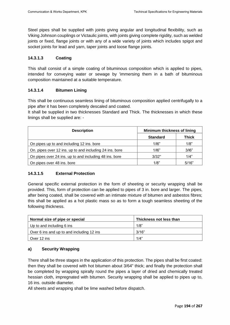
Page 194 of 267
Steel pipes shall be supplied with joints giving angular and longitudinal flexibility, such as
Viking Johnson couplings or Victaulic joints, with joints giving complete rigidity, such as welded
joints or fixed, flange joints or with any of a wide variety of joints which includes spigot and
socket joints for lead and yarn, taper joints and loose flange joints.
14.3.1.3 Coating
This shall consist of a simple coating of bituminous composition which is applied to pipes,
intended for conveying water or sewage by 'immersing them in a bath of bituminous
composition maintained at a suitable temperature.
14.3.1.4 Bitumen Lining
This shall be continuous seamless lining of bituminous composition applied centrifugally to a
pipe after it has been completely descaled and coated.
It shall be supplied in two thicknesses Standard and Thick. The thicknesses in which these
linings shall be supplied are: -
Description Minimum thickness of lining
Standard Thick
On pipes up to and including 12 ins. bore 1/l6” 1/8”
On. pipes over 12 ins. up to and including 24 ins. bore 1/l6” 3/l6”
On pipes over 24 ins. up to and including 48 ins. bore 3/32" 1/4”
On pipes over 48 ins. bore 1/8” 5/16”
14.3.1.5 External Protection
General specific external protection in the form of sheeting or security wrapping shall be
provided. This, form of protection can be applied to pipes of 3 in. bore and larger. The pipes,
after being coated, shall be covered with an intimate mixture of bitumen and asbestos fibres;
this shall be applied as a hot plastic mass so as to form a tough seamless sheeting of the
following thickness.
Normal size of pipe or special Thickness not less than
Up to and including 6 ins 1/8”
Over 6 ins and up to and including 12 ins 3/16”
Over 12 ins 1/4”
a) Security Wrapping
There shall be three stages in the application of this protection. The pipes shall be first coated:
then they shall be covered with hot bitumen about 3/64" thick; and finally the protection shall
be completed by wrapping spirally round the pipes a layer of dried and chemically treated
hessian cloth, impregnated with bitumen. Security wrapping shall be applied to pipes up to,
16 ins. outside diameter.
All sheets and wrapping shall be lime washed before dispatch.
Communication & Works Department, KPK Techincal Specifications for Engineering Materials
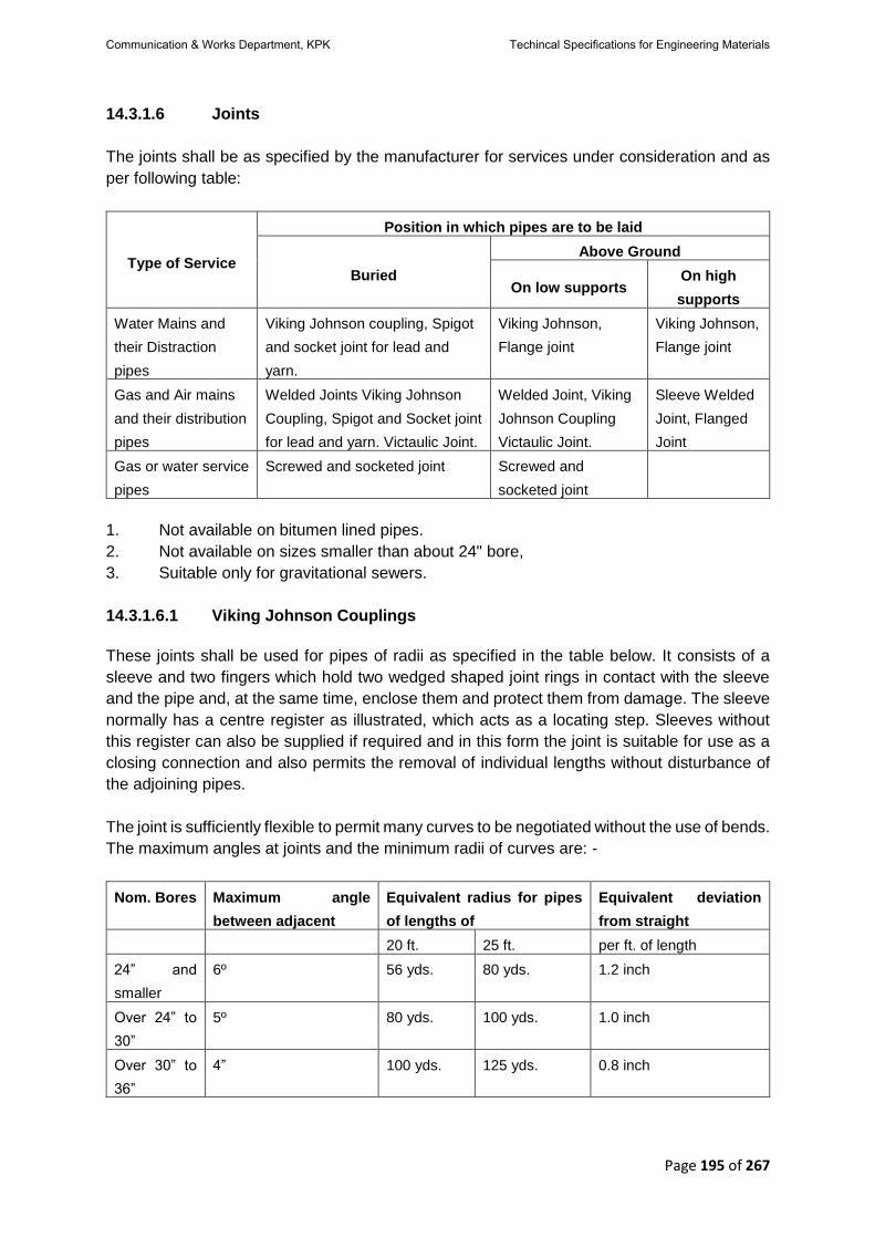
Page 195 of 267
14.3.1.6 Joints
The joints shall be as specified by the manufacturer for services under consideration and as
per following table:
Type of Service
Position in which pipes are to be laid
Buried
Above Ground
On low supports On high
supports
Water Mains and
their Distraction
pipes
Viking Johnson coupling, Spigot
and socket joint for lead and
yarn.
Viking Johnson,
Flange joint
Viking Johnson,
Flange joint
Gas and Air mains
and their distribution
pipes
Welded Joints Viking Johnson
Coupling, Spigot and Socket joint
for lead and yarn. Victaulic Joint.
Welded Joint, Viking
Johnson Coupling
Victaulic Joint.
Sleeve Welded
Joint, Flanged
Joint
Gas or water service
pipes
Screwed and socketed joint Screwed and
socketed joint
1. Not available on bitumen lined pipes.
2. Not available on sizes smaller than about 24" bore,
3. Suitable only for gravitational sewers.
14.3.1.6.1 Viking Johnson Couplings
These joints shall be used for pipes of radii as specified in the table below. It consists of a
sleeve and two fingers which hold two wedged shaped joint rings in contact with the sleeve
and the pipe and, at the same time, enclose them and protect them from damage. The sleeve
normally has a centre register as illustrated, which acts as a locating step. Sleeves without
this register can also be supplied if required and in this form the joint is suitable for use as a
closing connection and also permits the removal of individual lengths without disturbance of
the adjoining pipes.
The joint is sufficiently flexible to permit many curves to be negotiated without the use of bends.
The maximum angles at joints and the minimum radii of curves are: -
Nom. Bores Maximum angle
between adjacent
Equivalent radius for pipes
of lengths of
Equivalent deviation
from straight
20 ft. 25 ft. per ft. of length
24” and
smaller
6º 56 yds. 80 yds. 1.2 inch
Over 24” to
30”
5º 80 yds. 100 yds. 1.0 inch
Over 30” to
36”
4” 100 yds. 125 yds. 0.8 inch
Communication & Works Department, KPK Techincal Specifications for Engineering Materials
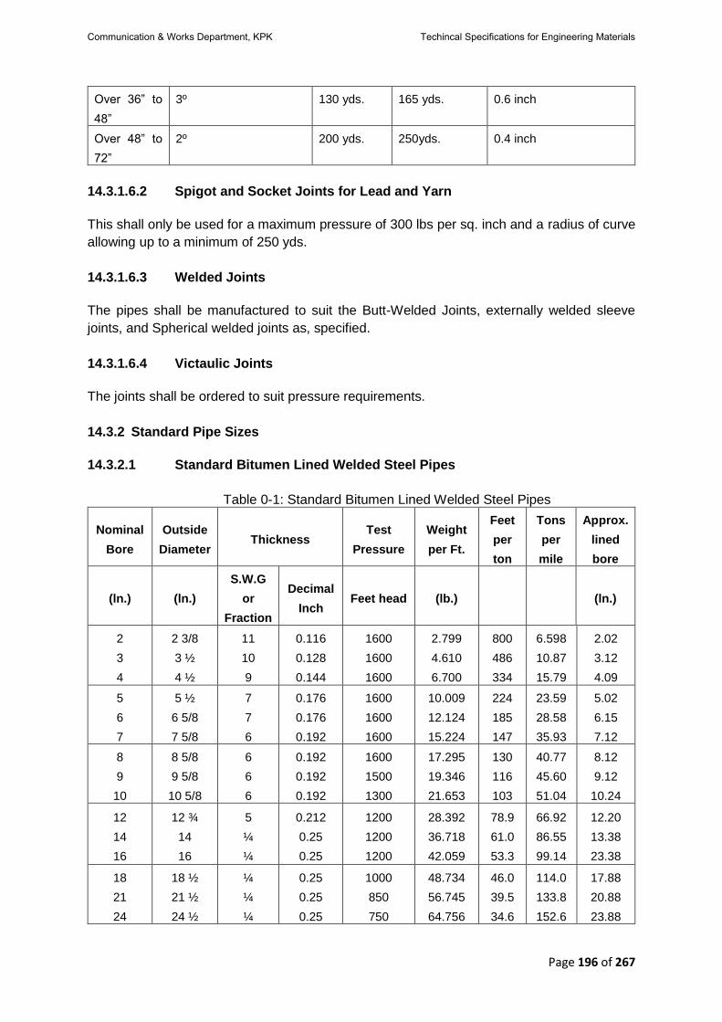
Page 196 of 267
Over 36” to
48”
3º 130 yds. 165 yds. 0.6 inch
Over 48” to
72”
2º 200 yds. 250yds. 0.4 inch
14.3.1.6.2 Spigot and Socket Joints for Lead and Yarn
This shall only be used for a maximum pressure of 300 lbs per sq. inch and a radius of curve
allowing up to a minimum of 250 yds.
14.3.1.6.3 Welded Joints
The pipes shall be manufactured to suit the Butt-Welded Joints, externally welded sleeve
joints, and Spherical welded joints as, specified.
14.3.1.6.4 Victaulic Joints
The joints shall be ordered to suit pressure requirements.
14.3.2 Standard Pipe Sizes
14.3.2.1 Standard Bitumen Lined Welded Steel Pipes
Table 0-1: Standard Bitumen Lined Welded Steel Pipes
Nominal
Bore
Outside
Diameter Thickness
Test
Pressure
Weight
per Ft.
Feet
per
ton
Tons
per
mile
Approx.
lined
bore
(ln.) (ln.)
S.W.G
or
Fraction
Decimal
Inch Feet head (lb.) (ln.)
2
3
4
2 3/8
3 ½
4 ½
11
10
9
0.116
0.128
0.144
1600
1600
1600
2.799
4.610
6.700
800
486
334
6.598
10.87
15.79
2.02
3.12
4.09
5
6
7
5 ½
6 5/8
7 5/8
7
7
6
0.176
0.176
0.192
1600
1600
1600
10.009
12.124
15.224
224
185
147
23.59
28.58
35.93
5.02
6.15
7.12
8
9
10
8 5/8
9 5/8
10 5/8
6
6
6
0.192
0.192
0.192
1600
1500
1300
17.295
19.346
21.653
130
116
103
40.77
45.60
51.04
8.12
9.12
10.24
12
14
16
12 ¾
14
16
5
¼
¼
0.212
0.25
0.25
1200
1200
1200
28.392
36.718
42.059
78.9
61.0
53.3
66.92
86.55
99.14
12.20
13.38
23.38
18
21
24
18 ½
21 ½
24 ½
¼
¼
¼
0.25
0.25
0.25
1000
850
750
48.734
56.745
64.756
46.0
39.5
34.6
114.0
133.8
152.6
17.88
20.88
23.88
Communication & Works Department, KPK Techincal Specifications for Engineering Materials

Page 197 of 267
27
30
33
27 ¾
30 ¾
33 ¾
9/16
5/16
5/16
0.2813
0.3125
0.3125
750
750
700
82.520
101.599
111.612
27.1
22.0
20.1
194.5
239.5
263.1
27.0
29.94
32.94
36
42
48
36 ¾
43
49
5/16
3/8
3/8
0.3125
0.375
0.375
650
650
600
121.626
170.736
194.969
18.4
13.1
11.5
286.7
402.4
459.1
35.94
42.06
48.06
54
60
66
72
55
61
67 ¼
73 ¼
7/16
½
8/16
5/8
0.4375
0.5
0.5625
0.625
600
600
600
600
254.977
323.113
400.678
484.836
8.8
6.9
5.6
4.6
601.0
761.6
944.4
1142.8
53.88
59.75
65.88
71.75
14.3.2.2 Standard Bitumen Lined Seamless Steel Pipes
Table 0-2: Standard Bitumen Lined Seamless Steel Pipes
Nominal
Bore
Outside
Diameter Thickness
Test
Pressure
Weight
per
Foot Feet
per
ton
Tons
per
mile
Approx.
lined
bore
(in.) (in.)
S.W.G
or
Fraction
Decimal
Inch Feet head (lb.) (in.)
2
3
4
2 3/8
3 ½
4 ½
8
7
7
.160
.176
.176
2300
2300
2300
3.785
6.249
8.129
582
358
276
8.922
14.73
19.16
1.93
3.02
4.02
5
6
5 ½
6 5/8
7 5/8
7
7
7
.176
.176
.176
2300
2200
2200
10.009
11.889
12.124
224
188
185
23.59
28.02
28.58
5.02
6.02
6.15
7
8
9
7 5/8
8 5/8
9 5/8
5
5
4
.212
.212
.212
2200
2100
2100
16.786
19.051
23.277
133
118
96.2
39.57
44.91
54.287
7.08
8.08
9.04
10
12
-
-
10 ¾
12 ¾
14
16
9/32
5/16
3/8
3/8
.2813
.3125
.375
.375
2100
2100
2100
2100
31.450
41.516
54.575
62.586
71.2
54.0
41.0
35.8
74.13
97.86
128.6
147.5
10.06
12.00
13.13
15.13
The limited range of thicknesses shown in the tables covers normal requirements for this class
of pipe. Thicker pipes may be supplied if required to meet special conditions as per drawings
or as directed by the Engineer in Charge.
All particulars, except the normal bores and test pressures, are subject to manufacturing
tolerances. These weights do not include bituminous protections or joints.
Communication & Works Department, KPK Techincal Specifications for Engineering Materials

Page 198 of 267
This dimension applies to standard bitumen lining. If thick bitumen lining not ordinarily applied
on water mains were used, the dimension would be slightly reduced. The sizes are not in
frequent production, and should be avoided where possible.
14.3.2.3 Dimensions of Shouldered Steel Pipes and Victaulic Joints
Pipes Joints
Nom-
inal
Bore
Outside
Diameter Ds L
Distance
b/w
Pipes
E
outside
dia. of
joint
A
Outside
distance
between
edges
of bolts
B
Width
of
joint
C
Weight Working
Pressure
in. in. in. in. in. in. in. in. in. in.
2
3
2 3/8
3 ½
2 5/8
3
13/16
5/8
5/8
1/8
1/8
3 15/16
5 3/8
5 15/16
7 1/4
1-
15/16
1 -7/8
3
5 1/2
600
600
4 4½ 4
15/16 11/16 1/8
6 9/16
6 1/2
8 7/8
8 3/4
2
2 1/2
7 1/4
7 600
5
6
7
5 ½
6 ½
10 ¾
9
13/16
6 7/8
11 ¼
11/16
11/16
11/16
1/8
1/8
1/8
7 ½
8 9/16
9 11/16
9 ½
10 3/8
11 9/16
2 1/32
2 1/32
2 1/32
8 ¼
9 ½
10 ½
500
400
400
8
9
10
8 5/8
9 5/8
10 3/4
9 1/8
10
1/8
11
1/4
13/16
13/16
13/16
1/8
1/8
1/8
11 ½
12 ½
13 5/8
13 7/8
14 15/16
16 1/8
2 1/2
2 1/2
2 1/2
20 ¼
21 ¾
23 ½
400
400
400
The working pressures shown are for water or oil.
Working pressures for air are: -
• Up to and including 5 in. nominal bore 200 ibs. Per sq. in.
• Over 5 in up to and including 12 in, nominal bore: (150 lbs, per sq, in.)
14.3.2.4 Pipes and Victaulic Joints
Pipes Joints
Nominal
Bore
Outside
Diameter Ds L E A B C Weight
Working
Pressure
in. in. in. in. in. in. in. in. in. in.
- 16 16
½ 1 ¼
19
1/2
22
1/2
3
3
1/2
52 3/4
44
225
150
Communication & Works Department, KPK Techincal Specifications for Engineering Materials
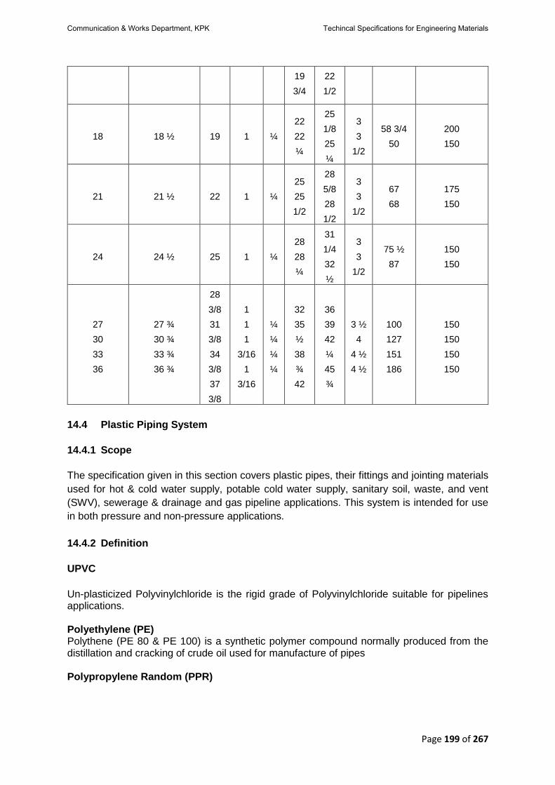
Page 199 of 267
19
3/4
22
1/2
18 18 ½ 19 1 ¼
22
22
¼
25
1/8
25
¼
3
3
1/2
58 3/4
50
200
150
21 21 ½ 22 1 ¼
25
25
1/2
28
5/8
28
1/2
3
3
1/2
67
68
175
150
24 24 ½ 25 1 ¼
28
28
¼
31
1/4
32
½
3
3
1/2
75 ½
87
150
150
27
30
33
36
27 ¾
30 ¾
33 ¾
36 ¾
28
3/8
31
3/8
34
3/8
37
3/8
1
1
1
3/16
1
3/16
¼
¼
¼
¼
32
35
½
38
¾
42
36
39
42
¼
45
¾
3 ½
4
4 ½
4 ½
100
127
151
186
150
150
150
150
14.4 Plastic Piping System
14.4.1 Scope
The specification given in this section covers plastic pipes, their fittings and jointing materials
used for hot & cold water supply, potable cold water supply, sanitary soil, waste, and vent
(SWV), sewerage & drainage and gas pipeline applications. This system is intended for use
in both pressure and non-pressure applications.
14.4.2 Definition
UPVC
Un-plasticized Polyvinylchloride is the rigid grade of Polyvinylchloride suitable for pipelines applications. Polyethylene (PE) Polythene (PE 80 & PE 100) is a synthetic polymer compound normally produced from the distillation and cracking of crude oil used for manufacture of pipes Polypropylene Random (PPR)
Communication & Works Department, KPK Techincal Specifications for Engineering Materials

Page 200 of 267
Polypropylene (PP), also known as polypropene, is a thermoplastic polymer used in a wide variety of applications including packaging, stationery, plastic parts and reusable containers of various types, laboratory equipment, loudspeakers, automotive components, and polymer banknotes.
Solvent Cement Solvent cement is a blend of three aggressive solvents and sufficient resin to provide a brushing consistency. It is not an adhesive. It is designed for solvent welding UPVC pipe joints by softening and swelling UPVC when applied on the pipe surface. Rubber Ring Rubber ring joint is a special joint in which one pipe has spigot end and the other pipe has
socket end with ring groove for rubber ring. The spigot end is inserted inside the socket end.
High Density Polyethylene (HDPE)
High-density polyethylene (HDPE) or polyethylene high-density (PEHD) is a thermoplastic polymer produced from the monomer ethylene. It is sometimes called "alkathene" or "polythene" when used for HDPE pipes. 14.4.3 References 14.4.3.1 British Standards
BS 3505 Specification for un-plasticized polyvinyl chloride (PVC-U) pressure pipes for
cold potable water
BS 4346 Joints and fittings for use with un-plasticized PVC pressure pipes
BS 2494 Specification for elastomeric seals for joints in pipework and pipelines
BS 4514 Specification for un-plasticized PVC soil and ventilating pipes, fittings and
accessories
BS 1277 Plastics piping systems. Thermoplastics piping systems for buried non-pressure
applications. Test methods for leak tightness of elastomeric sealing ring type
joints
14.4.3.2 European Standards
EN 1329 Plastics piping systems for soil and waste discharge (low and high temperature)
within the building structure. Un-plasticized polyvinyl chloride (PVC-U).
Specifications for pipes, fittings and the system
EN 1401 Plastics piping systems for non-pressure underground drainage and sewerage.
14.4.3.3 German Standards
DIN 8077 Polypropylene (PP) pipes - PP-H, PP-B, PP-R, PP-RCT - Dimensions (Foreign
Standard)
DIN 8078 Polypropylene (PP) pipes - PP-H, PP-B, PP-R, PP-RCT - General quality
requirements and testing (Foreign Standard)
Communication & Works Department, KPK Techincal Specifications for Engineering Materials

Page 201 of 267
DIN
16962
Pipe Joints and Elements for Polypropylene (PP) Pressure Pipelines, Types 1
and 2
DIN 8074 Polyethylene (PE) pipes- Dimensions (Foreign Standard)
DIN 8075 Polyethylene (PE) pipes - General quality requirements and testing
DIN
16963
Pipe Joints and Elements for High Density Polyethylene (HDPE) Pressure
Pipelines
DIN 3441 Un-plasticized polyvinyl chloride (PVC-U) valves
14.4.3.4 ISO (International Standard Organization)
ISO
3603
Fittings for un-plasticized polyvinyl chloride (UPVC) pressure pipes with elastic
sealing ring type joints; Pressure test for leakproofness
ISO
3604
Fittings for un-plasticized polyvinyl chloride (UPVC) pressure pipes with elastic
sealing ring type joints; Pressure test for leakproofness under conditions of
external hydraulic pressure
ISO
4633
Rubber seals - Joint rings for water supply, drainage and sewerage pipelines -
Specification for materials
ISO 264 Un-plasticized polyvinyl chloride (UPVC) fittings with plain sockets for pipes
under pressure; Laying lengths; Metric series
ISO
4427
Plastics piping systems - Polyethylene (PE) pipes and fittings for water supply
ISO
3458
Assembled joints between fittings and polyethylene (PE) pressure pipes ; Test
of leak proofness under internal pressure
ISO
3459
Polyethylene (PE) pressure pipes; Joints assembled with mechanical fittings;
Internal under-pressure test method and requirement
ISO
3501
Assembled joints between fittings and polyethylene (PE) pressure pipes -- Test
of resistance to pull out
ISO
3633
Plastics piping systems for soil and waste discharge (low and high temperature)
inside buildings -- Un-plasticized polyvinyl chloride (PVC-U)
ISO
4435
Plastics piping systems for non-pressure underground drainage and sewerage -
Un-plasticized polyvinyl chloride (PVC-U)
ISO
4437
Buried polyethylene (PE) pipes for the supply of gaseous fuels - Metric series -
Specifications
ISO
7508
Un-plasticized polyvinyl chloride (PVC-U) valves for pipes under pressure; Basic
dimensions; Metric series
ISO 265-
1
Pipes and fittings of plastics materials - Fittings for domestic and industrial waste
pipes - Basic dimensions: Metric series - Part 1: Un-plasticized poly(vinyl
chloride) (PVC-U)
ISO
1452-3
Plastics piping systems for water supply and for buried and above-ground
drainage and sewerage under pressure. Un-plasticized polyvinyl chloride
(UPVC). Fittings
ISO 580 Plastics piping and ducting systems - Injection-moulded thermoplastics fittings
- Methods for visually assessing the effects of heating
Communication & Works Department, KPK Techincal Specifications for Engineering Materials

Page 202 of 267
ISO
15874-1
Plastics piping systems for hot and cold water installations — Polypropylene
(PP)- General
ISO
15874-2
Plastics piping systems for hot and cold water installations — Polypropylene
(PP)- Pipes
ISO
15874-3
Plastics piping systems for hot and cold water installations — Polypropylene
(PP)- Fittings
14.4.3.5 PS (Pakistan Standard)
PS
4533
Polypropylene Pipes - General requirements and Testing (type 1, 2 and 3).
PS
4534
Polypropylene (PP) Pipes - dimensions.
PS
3051
Un-plasticized polyvinyl chloride (UPVC) pressure Pipes for cold potable water
PS
1915
Rubber seals - joints rings for water supply, drainage and sewerage pipelines -
specification for material pre-stressed concrete pressure Pipes (including fittings).
PS
3580
Polyethylene (PE) Pipes for water supply-specifications.
PS
4037
Thermoplastic waste pipe and fittings.
PS
3863
Un-plasticized polyvinyl chloride (PVC-U) Pipes and fitting for buried drainage and
sewerage system specification.
14.4.3.6 ASTM Standards
ASTM D
2513
Standard Specification for Polyethylene (PE) Gas Pressure Pipe, Tubing, and
Fittings
ASTM
D3035
Standard Spec for PE Pipe (DR-PR) Based on Controlled Outside Diameter
ASTM
D695
Standard Test Method for Compressive Properties of Rigid Plastics
ASTM
D2444
Standard Test Method for Determination of the Impact Resistance of
Thermoplastic Pipe and Fittings by Means of a Tup (Falling Weight)
ASTM
D2122
Standard Test Method for Determining Dimensions of Thermoplastic Pipe and
Fittings
ASTM
D2774
Practice for Underground Installation of Thermoplastic Pressure Piping
14.4.4 Source Approval for plastic Pipes
The contractor shall submit to the Engineer for his review and approval full detail of the
proposed sources of plastic piping system. These sources of pipe and fitting supply shall be
regularly and thoroughly examined to ensure that the quality of the material supplied is
Communication & Works Department, KPK Techincal Specifications for Engineering Materials

Page 203 of 267
satisfactory and that it does not deteriorate during the entire performance period of the project.
Predefined sources may be specified in the Special Provisions of Contract Documents.
14.4.5 Performance Criteria/Quality Requirements
14.4.5.1 Un-plasticized Polyvinyl Chloride (UPVC) Pipes & Fittings
• Un-plasticized PVC non-pressure pipes for water supply & distribution shall comply
with the requirements of BS 3505 and PS 3051 Class 0.
• Un-plasticized PVC pressure pipes for water supply and distribution for use at
pressures up to 14 bar at 20º C shall comply with the requirements of BS 3505/PS
3051, Class B, C, D, E.
• Joint and fittings for use with un-plasticized PVC pressure pipes shall comply with the
requirements of BS 4346 & ISO 3603/3604.
• Un-plasticized PVC soil, waste and vent pipes shall comply with the requirements of
ISO 3633, EN 1329, BS 4514 & PS 4037.
• Joints and fittings for use with un-plasticized PVC soil, waste and vent pipes shall
comply with the requirements of ISO of ISO 3633, EN 1329, BS 4514 & PS 4037.
• Un-plasticized PVC sewerage & drainage pipes shall comply with the requirements of
ISO 4435 & EN 1401 & PS 3863.
• Joints & fittings for use with un-plasticized PVC sewerage & drainage pipes shall
comply with the requirements of ISO 4435 & EN 1401 & PS 3863.
• Rubber seals - joints rings for use with un-plasticized PVC pressure pipes shall comply
with requirements of BS 2494, ISO 4633 & PS 1915.
• Specifications and tolerances of un-plasticized PVC fittings under pressure shall meet
the requirements of ISO 264.
• Diameters and basic dimensions of un-plasticized PVC valves for pipes under pressure
of 10 bar to 16 bar shall meet the requirements of ISO 7508, 3441-2~6.
• Fittings for domestic and industrial waste pipes of un-plasticized PVC shall meet with
the requirements of ISO 265-1.
• Specifications of injection moulded fittings shall meet the requirements of ISO 580.
14.4.5.2 Polyethylene (PE) / High Density Polyethylene (HDPE) Pipes & Fittings
• Polyethylene (PE) pipes for water supply & distribution shall comply with the
requirements of DIN 8074/8075, ASTM D3035, ISO 4427 & PS 3580.
• Joint & fittings for use with polyethylene water & distribution pipes shall comply with
the requirements of ISO 3501, ISO 3458/3459 & DIN 16963.
• Polyethylene pipes for gas pipeline shall comply with the requirement of ISO 4437,
DIN 8074/8075 and ASTM D2513.
• Joints and fittings for use with polyethylene gas pipeline shall comply with the relevant
requirements.
14.4.5.3 Polypropylene (PP) / Polypropylene Random (PPR) Pipes & Fittings
• Polypropylene pipes for hot and cold-water supply shall comply with the requirement
of DIN 8077/8078, ISO 15874-2 and PS 4533/4534.
Communication & Works Department, KPK Techincal Specifications for Engineering Materials

Page 204 of 267
• Joint and fittings for use with polypropylene hot & cold-water supply pipes shall comply
with the requirement of DIN 16962, ISO 15874-3 & PS 4533/4534.
14.4.6 Submittal and Sampling of Plastic Pipes
• Sections of pipe for visual inspection shall be randomly selected by the Engineer.
• The methods of obtaining samples of pipes and fittings for testing shall be carried out
as described in ISO 3603, ISO 7508, DIN 3441 1~6.
• The Contractor shall provide samples from each consignment of pipes delivered to the
Site, or as required by the Engineer. The Contractor shall supply to the Engineer test
certificates with the appropriate standard in respect of the samples of pipes from the
work-site.
14.4.7 Testing of Material for Plastic Pipes
• The quality requirement and testing of UPVC pipes and fittings shall be in accordance with ISO 1452-3.
• The quality requirements and testing of UPVC valves shall be in accordance with the provisions of DIN 3441-1.
• Pipe stiffness shall be tested in accordance with the requirements of ASTM D695.
• Impact Resistance of pipes and fittings shall be tested in accordance with requirements of ASTM D2444.
• Physical dimensions of plastic pipes and fittings shall be in accordance with ASTM D2122.
• Underground installation of plastic pipes and fittings shall be in accordance with ASTM D2774
• Sufficient time shall be allowed for the Engineer's review of test results. 14.4.8 Delivery, Storage and Handling
• Unloading at the Site shall be made during normal day working hours.
• The Contractor shall handle, transport, unload and store the pipe using the proper equipment and preventing any damage to the pipe. For this purpose the Contractor shall provide and install all suitable equipment at the pipe yard and shall be responsible for all handling and storage prior to laying of the pipes. The facilities, equipment and procedure for handling of pipe shall be approved in advance by the Engineer.
• Transport of pipe work to the Site shall be in accordance with the program of laying of pipeline, submitted by the Contractor and approved by the Engineer.
• Any part of the pipe work which is ready to be brought to the Site, shall be tested and examined by the Engineer in the factory to ensure that it conforms to the relevant specifications.
• Any portion or part of the pipe work which is defective or in the opinion of the Engineer is not in accordance with the specification shall be rejected. The Engineer shall decide whether this portion or part of the pipe work may be repaired or shall be replaced by a new portion or part of the pipe work.
• All rejected portions shall be replaced or repaired by the Contractor at his own cost, as directed by the Engineer.
• The pipe shall be handled without causing any damage to the ends of the pipe.
• Pipe stored along the trench side shall be supported by padded wooden timbers place under the pipe to hold the pipe off the ground.
• Dragging or skidding the pipe will not be permitted.
Communication & Works Department, KPK Techincal Specifications for Engineering Materials
Page 205 of 267
14.4.9 Size
Size of pipe and fittings shall be as specified.
14.4.10 Measurement
The measurement of pipe shall be in feet or metre as specified.
14.4.11 Rate
The unit rate shall include the cost of the pipe, jointing materials, specials, sorting, packing
and delivering at Site of Work, to be defined in the Conditions of Contract.
14.5 Reinforced Concrete Sewer Pipe, Storm Drain and Culvert, Conforming to Astm C76-14
14.5.1 Scope
This specification covers reinforced concrete pipe intended to be used for the conveyance of
sewerage, industrial wastes, and storm water, and for the construction of culverts for sewer
lines.
14.5.2 Classification
Pipe manufactured in accordance with this Annexure/specification shall be of classes identified as Class II & Class III with Wall B. The corresponding strength requirements are prescribed in Table 14 3 and Table 14 4 respectively in section 14.5.5 below.
14.5.3 Basis of Acceptance
The acceptance of the reinforced cement concrete pipes shall be on the Basis of Plant Load
Bearing Test, Material Tests, and Inspection of Manufactured Pipe for Visual Defects and
Imperfection.
Acceptability of the pipe in all diameters and classes produced in accordance with section
14.5.3 below shall be determined by the result of the three-edge bearing tests for either the
load to produce a 0.01 in. crack and the ultimate strength of the pipe; by such material test as
are required in section 14.5.8.1.1, 14.5.8.1.2, and 14.5.8.4 below by absorption test on
selected samples of the finished pipe to determine its conformance with the accepted design
and its freedom from defects.
Pipe shall be considered ready for acceptance when it conforms to the requirements as
indicated by the specified tests.
14.5.4 Materials for RCC Pipes 14.5.4.1 Cement
Communication & Works Department, KPK Techincal Specifications for Engineering Materials

Page 206 of 267
The Portland cement which is required to be used in the manufacture of the reinforced cement
concrete pipes shall conform to the requirements of ASTM C 150 and as detailed in relevant
sections of Chapter 3 of Book – I and Chapter 6 of Book – II.
14.5.4.2 Aggregates
The coarse aggregate and fine aggregate shall conform to the specification given in relevant
sections of Chapter 6 of Book – I & Book – II.
14.5.4.3 Admixtures and Blends
Admixtures and blends may be used with the approval of the Employer as per specifications
given in relevant sections of Chapter 6 of Book – II.
14.5.4.4 Steel Reinforcement
Reinforcement shall consist of wire conforming to ASTM A82 or ASTM A496 or of wire fabric
conforming to specification ASTM A185 or Specification ASTM A497 or of deformed bars of
Grade 40 steel conforming to Specification ASTM A615. Relevant Section of Chapter 6 of
Book – II may be referred to for steel reinforcement
14.5.5 Design
14.5.5.1 Design Tables
The diameter, wall thickness, compressive strength of the concrete and area of the
circumferential reinforcement shall be as prescribed for Class II and III, Wall B in Tables Table
14 3 & Table 14 4, below;
Table 14 3: Design Requirements for Class ll Reinforced Concrete Pipe A
4. Note-1: See Section -3 above for basis of Acceptance specified by the Client
The strength test requirements in pounds force per inner foot of pipe under the three-bearing
shall be D-load (test load expressed in pounds-force per linear foot per foot of diameter) to
produce a 0.01 in. crack or the D-loads to produce the 0.01 in. crack and the ultimate load as
specified below multiplied by the internal diameter of the pipe in feet.
D-load to produce a 0.01 in. crack 1000
D-load to produce the ultimate load 1500
Communication & Works Department, KPK Techincal Specifications for Engineering Materials

Page 207 of 267
WALL B
Internal Designated
Diameter
(in.)
Concrete Strength, 4000 psi
Elliptical Reinforcement C
(in2/linear ft. of pipe
wall)
Wall
Thickness
(in.)
Circular Reinforcement B
(in2/linear ft. of pipe
wall)
Inner Cage Outer
Cage
12
15
18
21
24
27
30
33
36
42
48
54
60
66
72
78
84
90
96
2
2-1/4
2-1/2
2-3/4
3
3-1/4
3-1/2
3-3/4
4
4-1/2
5
5-1/2
6
6-1/2
7
7-1/2
8
8-1/2
9
0.07b
0.07b
0.07b
0.07b
0.07b
0.13
0.14
0.15
0.12
0.15
0.18
0.22
0.25
0.31
0.35
0.40
0.46
0.51
0.57
-
-
-
-
-
-
-
-
0.7
0.09
0.11
0.13
0.15
0.19
0.21
0.24
0.28
0.31
0.34
-
-
0.07
0.07
0.07
0.11
0.12
0.13
0.13
0.17
0.20
0.24
0.28
0.34
0.39
0.44
0.51
0.57
0.63
Foot notes to the table herein are intended to be amplifications of tabulated requirement and
are to be considered applicable and binding as if they were contained in the body of the
specification.
a. For modified or special designs, see section 5.2. Steel areas may be interpolated
between those shown for variations in diameter, loading, or wall thickness. Pipe over 96 in. in
diameter shall have two circular cages or an inner circular plus one elliptical cage.
b. As an alternative to design requiring both inner and outer circular cages the
reinforcement may be positioned and proportioned in either of the following manners.
• An inner circular cage plus an elliptical cage such that the area of the elliptical cage
shall not be less than that specified for the outer cage in the table and the total area of the
inner circular cage plus the elliptical cage shall be less than that specified for the inner cage
in the table.
• An inner and outer cage plus an elliptical cage in accordance with Figure 14 1 below;
Communication & Works Department, KPK Techincal Specifications for Engineering Materials

Page 208 of 267
c. Elliptical steel must be held in place by means of holding rods, chairs, or other positive
means throughout the entire sting operation
Figure 14 1: Triple Cage Reinforcement
Table 14 4: Design Requirements for Class III Reinforced Concrete Pipe A
5. Note-1: See Section 14.5.3 for basis of Acceptance specified by the Client
The Strength test requirements in pounds force per inner foot of pipe under the three-bearing
shall be D-load (test load expressed in pounds-force per linear foot per foot of diameter) to
produce a 0.01 in. crack or the D-loads to produce the 0.01 in. crack and the ultimate load as
specified below multiplied by the internal diameter of the pipe in feet.
D-load to produce a 0.01 in. crack 1350
D-load to produce the ultimate load 2000
WALL B
Internal Designated Diameter (in.)
Concrete Strength, 4000 psi
Elliptical Reinforcement C
(in2/linear ft. of pipe wall)
Wall Thickness (in.)
Circular Reinforcement B (in2/linear ft. of pipe wall)
Inner Cage Outer Cage
12 15 18 21 24 27 30 33 36
2 2-1/4 2-1/2 2-3/4 3 3-1/4 3-1/2 3-3/4 4E
0.07 0.07B 0.07B 0.07B 0.07B 0.16 0.18 0.20 0.17
- - - - - - - - 0.10
- - 0.07 B 0.07 B 0.07 B 0.14 0.15 0.17 0.19
Communication & Works Department, KPK Techincal Specifications for Engineering Materials

Page 209 of 267
42 48 54 60 66 72 78 84
4.5 5 5-1/2 6 6-1/2 7 71-/2 8
0.21 0.24 0.29 0.34 0.41 0.49 0.57 0.64
0.13 0.14 0.17 0.20 0.25 0.29 0.34 0.38
0.23 0.27 0.32 0.38 0.46 0.54 0.63 0.71
Notes:
• For modified or special designs see 14.5.5 or with the permission of the purchaser utilize the provisions of Specification ASTM C655. Steel areas may be interpolated between those shown for variations in diameter, loading, or wall thickness. Pipe over 96 in. in diameter shall have two circular cages or an inner circular plus one elliptical cage.
• As an alternative to design squiring both inner and outer circular cages the reinforcement may be positioned and proportioned in either of the following manners. As inner circular cage plus an elliptical cage such that the area of the elliptical cage shall not be less than that specified for the outer cage in the table and the total area of the inner circular cage plus the elliptical cage shall be less than that specified for the inner cage in the table.
• An inner and outer cage plus an elliptical cage in accordance with Figure 14 1 above.
• Elliptical steel must be held in place by means of holding rods, chairs, or other positive means throughout the entire sting operation.
The strength test requirement in pounds-force per linear foot of pipe under the three-edge-
bearing method shall be either the D-load (test load expressed in pounds-force per linear foot
per foot of diameter) to produce a 0.01 in crack to the D-load to produce the 0.01 in crack and
the ultimate load as specified below multiplied by the internal diameter of the pipe in feet.
D-load to produce a 0.01 in crack = 2000
D-load to produce the ultimate load = 3000
14.5.5.2 Modified and Special Design
If permitted by the manufacturer many request approval by the purchaser of modified designs
in this section; or special designs for size and loads beyond those shown in Table 14 3 & Table
14 4.
Such modified or special designs shall be based on rational or empirical evaluations of the
ultimate strength and cracking behaviour of the pipe and shall fully describe to the purchaser
any deviations from the requirements of this section. The descriptions of modified or special
designs shall include the wall thickness, the concrete strength, and the areas, type placement,
number of layers and strength of the steel reinforcement.
The manufacturer shall submit to the purchaser proof of the adequacy of the proposed
modified or special design. Such proof may comprise the submission of certified three-edge-
bearing test already made, which are acceptable to purchaser or, if such three-edge-bearing
test are not available or acceptable, the manufacturer may be required to perform proof test
of size and classes selected by the purchaser to demonstrate the adequacy of the proposed
design.
Communication & Works Department, KPK Techincal Specifications for Engineering Materials
Page 210 of 267
Such pipe must meet all of the test and performance requirements specified by the purchaser
in accordance with section 14.5.3.
14.5.5.3 Area
In this specification, when the word area is not described by adjective, such as cross-section
or single wire it shall be understood to be the cross-sectional area of reinforcement per unit
lengths of pipe.
14.5.5.4 Reinforcement
14.5.5.4.1 Circumferential Reinforcement
A line of circumferential reinforcement for any given total area may be composed of two layers
for pipe with wall thickness of less than 7 in. or three layers for pipe with thickness of 7 in. or
greater. The layers shall not be separated by more than the thickness of one longitudinal plus
1/2 in. The multiple layers shall be fastened together to form a single case all other
specification requirement such as laps, wades, and tolerances of placement in the wall of the
pipe, etc. shall apply to this method of fabricating a line of reinforcement.
• Where one line of circular reinforcement is used. It shall be placed from 35 to 50% of the wall thickness from the inner surface to the pipe, except that for wall thickness less than 2-1/2 in., the protective cover of the wall of the pipe shall be 3/4 in.
• In pipe having two lines of circular reinforcement each line shall be so placed that the protective covering of concrete over the circumferential reinforcement in the wall of the pipe shall be 1 in.
• In pipe having elliptical reinforcement with wall thickness 2-1/2 in. or greater, the reinforcement in the wall of the pipe shall be so placed that the protective covering of concrete over the circumferential reinforcement shall be 1 in. from the inner surface of the pipe at the vertical diameter and 1 in. from the outer surface of the pipe at the horizontal diameter. In pipe having elliptical reinforcement with wall thickness less than 2-1/2 in., the protective covering of the concrete shall be 3/4 in. at the vertical and horizontal diameters.
• The location for the reinforcement shall be subject to the permissible variations in dimensions given in section 14.5.10.5.
• The spacing center to center of circumferential reinforcement in a cage shall not exceed 4 in. for pipe up to and including Pipe having a 4 in. wall thickness nor exceed the wall thickness for larger pipe and shall in no case exceed 6 in.
• Where the wall reinforcement does not extend into the joint, the maximum longitudinal distance to the last circumferential from the inside shoulder of the bell or the shoulder of the spigot shall be 3 in. except that if this distance exceeds in half the wall thickness, the pipe wall shall contain at least a total reinforcement area of the minimum specified area per linear foot times the laying length of the pipe section. The minimum cover on the last circumferential near the spigot shoulder shall be 1/2 in.
• Where reinforcement is in the bell or sponger the minimum end cover on the last circumferential shall be in the bell or 1/4 in. in the spigot
• The continuity of the circumferential reinforcing steel shall not be destroyed during the manufacture of the Pipe except that when agreed upon by the purchaser. Left eyes or holes may be provided in each pipe for the purpose of handling.
• If splices are not welded, the reinforcement shall be lapped not less than 20 diameters for plain bars and cold-worked wire, and 40 diameters for plain bars and cold-drawn wire.
Communication & Works Department, KPK Techincal Specifications for Engineering Materials

Page 211 of 267
• When splices are welded and are not lapped to the minimum requirements above pull tests of representative specimens shall develop at least 50% the minimum specified strength of the steel and there shall be a minimum lap of 2 in. For butt-welded splices in bars or wire permitted only with helically wound cages, pull tests of representative specimens shall develop least 75% of the minimum specified strength of the steel.
14.5.5.4.2 Longitudinal Reinforcement
Each line of circumferential reinforcement shall be assembled into cage that shall contain
sufficient longitudinal bars or members to maintain the reinforcement in shape and in position
within the form to comply with permissible variations. The exposure of the end of longitudinal,
stirrups, or spacers that have been used to position the cages during the placement of the
concrete shall not be a cause for rejection.
14.5.5.4.3 Joint Reinforcement
The length of the joint as used herein means the inside length of the bell or the outside length
of the spigot from the shoulder to the end of the pipe section. The end distances or cover on
the end circumferential shall apply to any point on the circumference of the pipe or joint. When
convoluted reinforcement is used, these distances and reinforcement areas shall be taken
from the points on the convolutions closest to the end of the pipe section. Unless otherwise
permitted by the owner, the following requirements for joint reinforcement shall apply;
14.5.5.4.4 Joint Reinforcement for Non-Rubber Gasket Joints:
For pipe 900 mm and larger in diameter, either the bell or spigot shall contain circumferential
reinforcement. This reinforcement shall be an extension of a wall cage, or may be a separate
cage of at least the area per metre of that specified for the outer cage or one-half of that
specified for single cage wall reinforcement, whichever is less.
Where bells or spigots require reinforcement, the maximum end cover on the last
circumferential shall be one-half the length of the joint or 75 mm, whichever is less.
14.5.5.4.5 Joint Reinforcement for Rubber Gasket Joints:
For pipe 300 mm and larger in diameter, the bell ends shall contain circumferential
reinforcement. This reinforcement shall be an extension of the outer cage or a single wall
cage, whichever is less, or may be a separate cage of at least the same area per metre with
longitudinal as required in 14.5.5.4.2. If a separate cage is used, the cage shall extend into
the pipe with the last circumferential wire at least 25 mm past the inside shoulder where the
pipe barrel meets the bell of the joint.
Where bells require reinforcement, the maximum end cover on the last circumferential shall
be 50 mm.
14.5.6 Joints
The joints shall be of such design and the ends of the concrete pipe sections so formed that
when the sections are laid together they will make a continuous line of pipe with a smooth
Communication & Works Department, KPK Techincal Specifications for Engineering Materials

Page 212 of 267
interior free from appreciable irregularities in the flow line, all compatible with the permissible
variations given in Section 14.5.10.
14.5.7 Manufacture
14.5.7.1 Mixture
The aggregates shall be sized, graded, proportioned and mixed with such proportion of
cement and water as will produce a homogeneous concrete mixture of such quality that the
pipe will conform to test and design requirements of this specification. All concrete shall have
a water-cement ration not exceeding 0.53 by weight. All pipe manufactured under the provision
of this specification shall contain a minimum of 470 lb of cement/yd. concrete unless mix
design with a lower cement content demonstrate that the quality and performance of the pipe
meet the requirement of this specification.
14.5.7.2 Curing
Pipe shall be subjected to any one of the methods of curing described below or to any other
method or combination of method approved by the purchaser that will give satisfactory results.
The pipe shall be cured for a sufficient length of time so that the specified D-load is obtained
when acceptance is based on clause (i) of section 14.5.3 or so that the concrete will develop
the specified compressive strength at 28 days or less when acceptance is based on clause
(ii) of section 14.5.3.
14.5.7.3 Steam Curing
Concrete pipe may be placed in curing chamber, free of outside drafts, and cured in a moist
atmosphere maintained by the injection of steam for such time and such temperature as may
be needed to enable the pipe to meet the strength requirements.
14.5.7.4 Water Curing
Concrete pipe may be water-cured by covering with water saturated material or by a system
of perforated pipes, mechanical sprinklers, porous hose etc.
14.5.7.5 Chemical Curing
A sealing membrane conforming to the requirement of Specification C 309 may be applied
and should be left intact until the required strength requirements are met. The concrete at the
time of application shall be within 10°F of the atmospheric temperature. All surfaces shall be
damp when the compound is applied.
The manufacturer may, at his option, combine the methods described in sections 14.5.7.3 to
14.5.7.5 provided the required concrete compressive strength is attained.
14.5.8 Physical Requirements
The specified number of pipes required for the test shall be furnished without charge by the
manufacturer and shall be selected at random by the purchaser and shall be pipe that would
Communication & Works Department, KPK Techincal Specifications for Engineering Materials

Page 213 of 267
not otherwise be rejected under this specification. The selection shall be made at the point or
points designated by the purchaser when placing the order.
14.5.8.1 Number and Type of Test Requirement for Various Delivery Schedules 14.5.8.1.1 Preliminary test for Extended Delivery Schedules
A purchaser of pipe, whose needs require shipments at intervals over extended periods of
time, shall be entitled to such test, preliminary to delivery of pipe, as are required by the type
of basis of acceptance specified by the purchaser in 14.5.3, of not more than three section of
pipe covering each size in which he is interested.
14.5.8.1.2 Additional test for Extended Delivery Schedules
After a preliminary test described in 14.5.8.1.1 a purchaser shall be entitled to additional test
in such numbers and at such times as he may deem necessary, provided that the total number
of pipe tested (including preliminary test) shall not exceed 1 % of the pipe delivered.
14.5.8.1.3 Test for Occasional Orders
A purchaser who places occasional order shall be entitled to test a number of pipes not to
exceed 2% of an order, and not to exceed five pieces of any one size; otherwise the number
of pipes desired for testing shall be included in the order.
14.5.8.2 External Load Crushing Strength
• The load to produce a 0.01 in crack or the ultimate load, as determined by the three-edge bearing methods as described in section 14.5.8.1.1 for each respective class of a 0.01 in crack and that have been tested only to the formation of a 0.01 in crack and that meet the 0.01 in crack load requirements shall be accepted for use.
• Pipe shall be considered as meeting the strength requirements when all test specimens conform to the strength recruitments. If any of the test specimens fail to meet the strength requirements the manufacturer shall be allowed retest of two additional specimens for each specimen that failed and the specimens should meet the strength requirements.
14.5.8.3 Concrete Strength
14.5.8.3.1 Compressive Strength
Compression test for satisfying the design concrete strength may be made on either standard ridded concrete cylinder compacted and cured in like manner as the pipe or in cross drilled form the wall of the pipe. If cylinders are tested, they shall be tested in accordance with Test Method ASTM C39. The average compressive strength of all cylinders tested shall be equal to or greater than the design strength. Not more than 10% of the cylinders tested shall fall below the design strength in no case shall any cylinder tested fall below 80% of the design strength. If cores are cut from the wall of the pipe and tested, they shall be cut and tested in accordance with the requirements of Methods ASTM C497. The compressive strength of each core tested shall be equal to or quarter than the design strength of concrete. If core does not meet the required strength another core from the same
Communication & Works Department, KPK Techincal Specifications for Engineering Materials
Page 214 of 267
pipe may be tested. If this core does not meet the required strength that pipe shall be rejected. Additional tests shall be made on other determine the acceptability of the lot. When the cores cut from a section of pipe successfully meet the strength requirement, the core holes shall be plugged and sealed by the manufacturer in a manner such that the pipe section will meet all the requirements of this specification. Pipe sections so sealed shall be considered as satisfactory for use.
14.5.8.4 Absorption
The absorption of a sample from the wall of the pipe as determined in accordance with
Methods ASTM C497 shall not exceed 9% of the dry mass for Method A or B. 15% for Method
B. Each Method A sample shall have a minimum mass of 0.1 kg. shall be free of visible cracks
and shall represent the full wall thickness of the pipe. When the initial absorption sample from
a pipe fails to conform to this specification the absorption test shall be made on another sample
from the same pipe and the results of the retest shall be substituted to the original test results.
14.5.8.5 Retests of pipe
When not more than 20% of the concrete test specimens fail to pass the requirements of the
specification the manufacturer may check his stock, eliminate whatever quantity of pipe they
desires and must mark those pipes that will not be shipped. The required test shall be made
on the balance of the order and the pipe shall be accepted, if they conform to the requirements
of this specification.
14.5.9 Test Equipment
Every manufacture furnishing pipe under this specification shall furnish all facilities and
permission for steel wire as describe in Methods ASTM C497.
14.5.10 Permissible Variations
14.5.10.1 Internal Diameter
The internal of 12 to 24 in. pipe shall vary not more than +1.5% from the design diameter. The
internal diameter of 27 in. and larger pipe shall not vary from the design diameter by more
than +1% of the design diameter or + in. whichever is greater.
14.5.10.2 Wall Thickness
The wall thickness shall not vary more than shown in the design or specified by more than
+5% combed or open texture that would adversely affect the function of the pipe.
14.5.10.3 Length of Two Opposite Sides
Variations in the laying length of two opposite sides of the pipe shall be more than 1/4 in. for
all sizes through 24 in. internal diameter, and not more than 1/8 in. /ft for all sizes larger with
a maximum of 5/8 in. in any length of pipe through 84 in. internal diameter or larger, except
where bevelled and pipe for laying on curves is specified by the purchaser.
Communication & Works Department, KPK Techincal Specifications for Engineering Materials

Page 215 of 267
14.5.10.4 Length of Pipe
The under run in length of a section of pipe shall not be more than 1/8 in./ft with a maximum
of 1/2 in. in any section of the pipe. The end cover requirements of Section 8 and 12 shall
apply.
14.5.10.5 Position or Area of Reinforcement
14.5.10.5.1 Position
The maximum variation in the position of the reinforcement shall be +10% of the wall thickness
or +1/2 in. whichever is greater. Pipe having variations in the position of the reinforcement
exceeding these specified above shall be accepted if the three-edge-bearing strength
requirements obtained on a representative specimen are met in no case, however the cover
over the circumferential reinforcement shall be less than 1/4 in. as measured to the end of the
spigot or 1/2 in. as measured to any other surfaces of non-rubber gasket joints or gasket
grooves in rubber gasket joints. If convoluted reinforcement is used the convoluted
circumferential end wire may be at the end surface of the joint providing the alternate
convolutions have at least cover from the end surface.
14.5.10.5.2 Area of Reinforcement
Reinforcement will be considered as meeting the design requirements, if the area computed
on the basis of nominal area of the wire or bars used, equals or exceeds the requirements of
sections 14.5.5.4.1 or 14.5.5.4.2. Actual area of the reinforcing used may vary from the
nominal area according to permissible variations of the standard specifications for the
reinforcing. When inner cage and outer cage reinforcing is used, the inner cage nominal area
may vary to the lower limit of 85 % of the elliptical nominal area and the outer cage nominal
area may vary to the lower limit of 51 % of the elliptical nominal area provided that the total
nominal area of the inner cage plus the outer cage shall not vary beyond the lower limit of 140
% of the elliptical nominal area.
14.5.11 Repairs
Pipe may be repaired, if necessary, because of imperfections in manufacture or damage
during handling and will be acceptable if, in the opinion of the owner, the repaired pipe
conforms to the requirements of this specification.
14.5.12 Inspection
The quality of materials, the process of manufacture and the finished pipe shall be subjects to
inspection and approval by an inspector employed by the purchaser.
14.5.13 Rejection
Pipe shall be subject to rejection on account of failure to conform any of the specification
requirements. Individual sections of pipe may be rejected because of any of the following: -
Communication & Works Department, KPK Techincal Specifications for Engineering Materials

Page 216 of 267
• Fracture or crack passing through the wall except for a single and crack that does not
exceed the depth of the joint.
• The ends of the pipe are not normal to the wall and centerline of the pipe within the
limits of variation given in 14.5.10.3 and 14.5.10.4.
• Damaged or cracked ends where such damage would prevent marking a satisfactory
joint.
• Any continuous crack having a surface width of 0.01 in. or more and extending for a
length of 12 in. or more regardless of position in the wall of the pipe.
14.5.14 Marking
The following information shall be legibly marked on each section of pipe.
i. The pipe class and specification designation.
ii. The date of manufacture.
iii. The name or trademark of the manufacturer and identification of plant.
iv. One end of each section of pipe with elliptical or quadrant reinforcement shall be clearly
market during the process of manufacturing or immediately thereafter, on the inside and the
outside of opposite wall along the minor axis of the elliptical reinforcing or along the vertical
axis for quadrant reinforcing.
Markings shall be indented on the pipe section or painted thereon with waterproof paint.
Communication & Works Department, KPK Techincal Specifications for Engineering Materials

Page 217 of 267
CHAPTER – 15 MISCELLANEOUS 15.1 Asbestos Cement Sheets
Asbestos Cement products are made by a combination of Portland Cement with asbestos fibers. These are usually fragile and easily -breakable by expansion- and contraction, by shock and by strong wind. The fibers act as a sort of reinforcement and their products are stronger and more resilient than pure cement sheets. These are available in flat as well as corrugated form.
15.2 Flat Asbestos Cement Sheets
15.2.1 Description Flat sheets shall he rectangular, have a plain surface on one side and shall have neatly trimmed edges. 15.2.2 Tolerance The linear dimensions of flat sheets shall not vary in dimension from these Specified by more than 0.25 %. They shall be tested for thickness by stacking 20 sheets together and the difference between actual height and the theoretical height shall not exceed 10%. 15.2.3 Breaking Strength The average breaking load of 5 square specimens 10" X 10" cut from fiat sheets, when tested wet over a 9” span shall not be less than the values given below: -
Type Thickness Tested with the fibers running parallel to the bearers (lbs.)
Tested with the fibers running at right angle to the bearers (lbs.)
3/32” 34 48
Flat Sheets
3/16” 49 69
¼” 58 123
5/16” 137 192
3/8” 196 276
If the breaking strength of any specimen is less than 70% of the average breaking strength of six specimens tested, a further six specimens shall be tested and the results combined with those of the previous 5 results, the lowest result having been eliminated. The breaking strength of any one of 11 specimens shall not be less than 70% of the average breaking strength of the specimens. 15.2.4 Colours Pigments that are embodied in the asbestos cement for colouring purposes shall be of permanent colour. They shall not contain substances deleteriously affecting cement, such as lead oxide, the proportions of water-soluble chloride and of water-soluble sulphates together shall not exceed 2.5 per cent by weight of Pigment. 15.2.5 Quality The finished product shall be free from visible defects and snail have been manufactured for at least 4 weeks before use.
Communication & Works Department, KPK Techincal Specifications for Engineering Materials

Page 218 of 267
15.2.6 Measurement Flat sheets shall be measured in square feet. The unit of measurement shall be 100 sq. ft. 15.2.7 Rate Unit rate shall include furnishing plain asbestos sheets conforming to above specifications at Site of Work as defined in the Conditions of Contract. 15.3 Corrugated Asbestos Cement Sheets
15.3.1 Description Corrugated sheets shall be classified according to the size and form of the corrugation as follows: -
Type of sheet Depth of Corrugation Centers of Corrugation
Small Section Under 2” 2 7/8” and 3”
Large Section 2” and Over 5 ¾” and 6”
Alternate Flat and Corrugated section 2” and Over 13 1/3 usually
15.3.2 Tolerance The sheets shall be corrugated in a true and regular manner. The corrugated sheets shall not vary from the standard dimension of length and width by more than 0.25%. 15.3.3 Breaking Strength When tested wet the average breaking load of 3 specimens shall not be less than the values given in the following table: -
Class of Sheet
Span at which tested
Minimum width of sheet tested
Minimum average breaking load per inch width of specimens tested.
ft. In. ft. In. Lbs.
Small Section 2 6 T 0 12
Large Section 3 6 3 0 26
Alternate flat and corrugated section
3 6 3 6 26
If the breaking strength of a specimen is less than 70 % Of the average breaking strength of the 3 specimens tested, a further 3 specimens shall be tested and the results combined with the result of the previous two tests, the lowest result having been eliminated. The lowest breaking strength of any one Of the 3 specimens shall not be less than 70 per cent of the average breaking strength of the specimens. 15.3.4 Colours Pigments that are embodied in the asbestos cement for colouring purposes shall be of permanent colour. They shall not contain substances deleteriously affecting cement, such; as lead oxide. The proportions of water-soluble chloride and of water-soluble sulphates together shall not exceed 2.5 per cent by weight of pigment.
Communication & Works Department, KPK Techincal Specifications for Engineering Materials

Page 219 of 267
15.3.5 Quality The finished product shall be free from visible defects and shall have been manufactured for at least four weeks before use. 15.3.6 Measurement Corrugated asbestos sheets shall be measured in Square Feet. The unit or measurement shall be 100 sq. ft. 15.3.7 Rate The unit rate shall include furnishing corrugated. asbestos cement sheets conforming to above specifications at Site of Work, as defined in the Conditions of Contract. 15.4 Bailies
15.4.1 Quality Bailies shall be of good quality timber properly seasoned, of mature growth, uniform in texture, straight in fiber, free from sapwood and live or dead knots and shall be procured from an approved source. 15.4.2 Taper In circumference Bailies shall not have a taper of more than 1 inch in 4 feet. 15.4.3 Classification Bailies shall be classified according to length and girth at both ends. 15.4.4 Measurement Bailies shall be measured in number. The unit of measurement shall be each bally. 15.4.5 Rate The unit rate shall include furnishing bailies conforming to above specifications at Site of Work, to be defined in the Conditions of Contract. 15.5 Bamboos
15.5.1 Quality Bamboo shall be of mature growth, free from splits, weevil rot, borehole and other defects and shall be procured from an approved source. Bamboos of 8-inch girth and over shall be semi-solid (fiber content not less than 755-per cent of cross-sectional area). 15.5.2 Classification Bamboo shall be classified according to length and girth at both ends. 15.5.3 Measurement Bamboo shall be measured in number. The unit of measurement shall be each bamboo.
Communication & Works Department, KPK Techincal Specifications for Engineering Materials

Page 220 of 267
15.5.4 Rate Unit rate shall include furnishing bamboo conforming to above specifications at Site of Work, to be defined in the Conditions of Contract. 15.6 Water Proof Building Paper
15.6.1 Quality Waterproof building or insulating paper shall be of an approved manufacture, stout, strong and thoroughly impregnated with waterproof composition and supplied in roil of standard widths. 15.6.2 Classification Building paper shall be classified according to the number of plies or laminations. 15.6.3 Measurement Building paper shall be measured in square feet. The unit of measurement shall be 100 square feet. 15.6.4 Rate The unit rate shall include furnishing building paper conforming to above specifications at Site Work to be defined in the Conditions of Contract. 15.7 Flat Steel Sheet
15.7.1 Description Flat steel sheets shall be made of tough mild steel, well annealed, ever, in temper and thickness, free from holes, cracks, blisters and other defects. The sheets shall be perfectly rectangular and the weight of any ten sheets to be within 7 1/2 per cent margin of the weights given below. 15.7.2 Weight The weight and thickness of sheets before galvanizing shall be as follows: -
a) No. 24 B.G. to be 0.02476-inch-thick and to weight 1.01 lbs. Per square foot. b) No. 22 B.G. to be 0.03125-inch-thick and to weight 1.27 lbs. Per square foot. c) No. 20 B.G. to be 0.0392-inch-thick and to weight 1.59 lbs. Per square foot.
The allowance for increase in weight by galvanizing shall be 2 oz. per square foot. 15.7.3 Galvanizing Galvanized steel sheets shall be thoroughly and evenly coated with zinc and shall be free from stains, bare spots and other defects. 15.7.4 Painting When not galvanized all sheets shall be coated immediately after manufacture with one coat of oil-paint: applied by dipping or brushing over the whole of the surface of each sheet.
Communication & Works Department, KPK Techincal Specifications for Engineering Materials

Page 221 of 267
15.7.5 Dimensions The sheets shall be of standard dimensions. The diagonal distance between opposite corner of sheets shall not differ by more than 3/4 inch. 15.7.6 Measurement Sheets shall be measured by weight. The unit of measurement shall be one cwt. 15.7.7 Rate The unit rate shall include furnishing flat steel sheets conforming to above specifications at Site of Work, to be defined in the Conditions of Contract.
15.8 Corrugated Steel Sheets
15.8.1 Description Corrugated steel sheets shall be made of tough mild steel, well annealed, even in temper and thickness, free from holes, cracks, blisters and other defects. Corrugated steel sheets shall be perfectly rectangular, the corrugations parallel with the sides and regular in curve, pitch and depth, and the weight of any ten sheets to be within 7 ½ percent margin of the weights given below. 15.8.2 Weight The weight and thickness of corrugated steel sheets before galvanizing shall be as follow: -
a) No. 24 B.G. to be 0.02476-inch-thick and to weight 1.01 lbs. Per square foot. b) No. 22 B.G. to be 0.03125-inch-thick and to weight 1.27 lbs. Per square foot. c) No. 20 B.G. to be 0.0392-inch-thick and to weight 1.59 lbs. Per square foot.
The allowance for increase in weight by galvanizing shall be 2 oz., per square foot of girthed surface which weight include both sides. 15.8.3 Galvanizing Galvanized corrugated steel sheets shall be thoroughly and evenly coated with zinc, and to be free from stains, bare spots and other defects. 15.8.4 Paint When not galvanized, all corrugated steel sheets shall be coaled immediately after manufacture with one coat of oil paint applied by dipping or brushing over the whole of the surface of each sheet. 15.8.5 Corrugations Unless Otherwise specifically ordered the corrugations shall be of standard pattern-3 inches pitch and 1/4 inch deep. The widths shall be as under: -
Communication & Works Department, KPK Techincal Specifications for Engineering Materials

Page 222 of 267
8/3 Corrugations 2 ft. 2 ins measured straight and 2 ft. 6 ins. Measured along the girth.
10/3 Corrugations 2 ft. 8 ins. Measured straight and 3 ft. measured along the girth.
15.8.6 Tolerance The diagonal distances between opposite corners of any sheet shall not differ by more than 3/4 inch. 15.8.7 Measurement Corrugated sheets shall be measured by weight. The unit of measurement shall be one cwt. 15.8.8 Rates The unit rate shall include furnishing corrugated steel sheets conforming id above specifications at Site of Work, to be defined in the Conditions of Contract. 15.9 Fire Bricks
15.9.1 Use Fire bricks are used for lining furnaces, boilers, combustion chambers, chimney flues and places where high temperature is developed. 15.9.2 Composition They are manufactured from the fire clay or refractory clay burnt at a high temperature (not less than 2500 0F.) for 12 to 14 days in special kilns. They are generally of white or yellowish white colour and close in texture. The dimensions are same as of an ordinary brick. 15.9.3 Manufacture Fire brick shall be manufactured from fire clay or refractory clay burnt at a high temperature not less than 2500 °F). 15.9.4 Quality Fire brick shall contain ne holes or flaws and the surface shall be free from windings. 15.9.5 Size Fire bricks shall be of regular and uniform size. 15.9.6 Test A test piece when heated to a temperature of 2462°F shall not show more than one percent linear expansion and when heated lo a temperature of 2876°F shall show no sign of fusion. They shall not absorb more than 10 per cent of water, by weight after an immersion for one hour.
Communication & Works Department, KPK Techincal Specifications for Engineering Materials

Page 223 of 267
15.9.7 Measurement The measurement of fire bricks shall be in numbers. The unit of measurement shall be one thousand bricks. 15.9.8 Rate The unit rate shall include furnishing fire brick, conforming to above specifications, sorting and stacking at Site of Work, to be defined in the Conditions of Contract. 15.10 Matting
15.10.1 Quality Matting shall be of the best available quality.
Type Details
Bamboo Split Bamboo (durma, etc.) woven as closely as possible
Flat Leaf Close woven from strips of any approved palm leaf (khajur, mazri, etc.) or from reeds beaten flat leaves (hogla, etc.)
Reed Any approved kinds of reed (pattal, sarkanda, etc.) bound or laced tightly together with strings as ordered.
15.10.2 Measurement Matting shall be measured in square feet. The unit of measurement shall he 100 square feet. 15.10.3 Rates The unit rate shall include furnishing matting conforming to above specifications at Site of Work, to be defined in the Conditions of Contract. 15.11 Glass
15.11.1 General Glass is an amorphous mixture of silicates of metals possessing the properties a hardness, brittleness and transparency. But modern Glass can be made so soft that it can be bent easily and nailed through very conveniently. Glass has roughly the following composition: -
Constituents Soda, Lime glass, window plate glass or ordinary glass
Lead glass, high glass glassware, cut glass and special glass.
Silica 70 to 76% 50%
Lime 10 to 13% --
Soda 10 to 13% --
Potash -- 17%
Red Lead -- 33%
Alumina 2 t0 4% --
15.11.1.2 Definitions Transparent Glass: Glass that transmits light and permits clear vision
through it.
Communication & Works Department, KPK Techincal Specifications for Engineering Materials
Page 224 of 267
Translucent Glass: Glass that transmits light with varying degrees of diffusion so that vision is not clear.
Safety Glazing Material: A glazing material that reduces or eliminates
unreasonable risk of death or serious injury as indicated by its remaining unbroken or breaking safety under the test specified.
Security Glazing Material: Glazing material that affords protection against a
specified level of attack. Weight: A traditional term used in the glass and glazing
industries to describe mass per unit area. 15.11.1.3 General Requirement 1. Material Glass should be of such quality that surface deterioration will not develop after glazing under normal conditions of use, provided the glass is cleaned at reasonable intervals. Glasses of the soda-lime-silica type will have adequate durability if they have the following composition. Silica and alumina together not less than 71%; Alkalis (Na2O; K2O) not greater than 15% Lime and magnesia together not less than 10%. 2. Thickness of Glass The minimum and maximum value when measured shall be within the tolerance listed in the appropriate table.
3. Out-Of-Square The rectangularity of a glass pane shall be such that, when checked by the method described in appendix A, it would fit into a rectangle of the maximum permitted dimensions for the normal size of the glass pane, and would circumscribe a rectangle of the minimum permitted size. 15.11.2 Manufacture of Glass The raw materials mentioned above are ground and sieved. They are then mixed in specified proportion and melted in a furnace termed as a "Tank Furnace". Raw materials are fed into it at one end and molten glass liquid is drawn out from the other end. Glass materials are prepared from this hot and viscous. glass fluid by fabrication which comprises the following processes: - 15.11.2.1 Blowing The blow pipe is dipped in the liquid glass to take out a small quantity of molten mass. It is then blown through to form a bulb and then a hollow cylinder which is subsequently cut and spread out to form a thin plate. The process of blowing could be done by a single blow pipe by an individual or through a series of blow pipes working automatically with the aid of a compressed air cylinder.
Communication & Works Department, KPK Techincal Specifications for Engineering Materials

Page 225 of 267
15.11.2.2 Flat Drawing and Rolling The viscous fluid is drawn in the form of plate by making an iron bar move, sidewise through it. It brings with it a thin film of glass. Sheet glass could also be prepared by the process of rolling. A continuous sheet is formed and the required size could be cut out from it. Rolled Glass is plainer and has a more even surface than the drawn glass. 15.11.3 Types of Glasses 15.11.3.1 Float or Polished plate glass
1. Clear Float or Polished Plate Glass Transparent glass, the surface of which are flat and parallel so that they provide clear, undistorted vision and reflection. Float glass is manufactured by allowing the glass from the tank furnace to flow across a bath of molten metal. Polished plate glass is produced by grinding, smoothing and polishing the surfaces of rough cast glass made sufficiently thick to allow the surface to be worked down to the required plate thickness. Generally, clear float glass has superseded polished plate glass in thickness up to 25 mm. Polished plate glass is still available in thickness greater than 25 mm and up to 38 mm.
2. Body Tinted Float Glass or Polished Plate Glass Transparent glass in which the whole body of the glass is tinted. Such glass reduces solar radiation transmission by increased absorption. Tints available are green, grey and bronze. Thickness available are 4mm, 5mm, 6mm, 10mm and 12 mm; whether all thickness is available in each tint depends on the manufacturer. Normal maximum sizes may differ from those for clear float glass.
3. Surface Modified Tinted Float Glass Transparent glass which, during manufacture, has a coloured layer of metal ions injected into the glass. Solar control properties are provided by an increase in reflection and absorption. Generally available thicknesses are 6mm, 10mm and 12mm. Normal maximum sizes may differ from those for clear float glass.
4. Surface Coated Float Glass Transparent glass which has a reflective surface layer. The reflection surface layer, the reflective surface layer may be on a clear or tinted base glass. Transmission of solar radiation is reduced by increase in reflection and absorption and the glass has a coloured metallic appearance. For the thickness and sizes available the manufacturers literature should be consulted.
5. Availability of Float and Polished Plate Glass Table gives the range of thickness and tolerances, weights, cutting tolerances and maximum sizes normally available.
Nominal Thickness
Tolerance on Thickness
Approx. weight
Cutting Tolerance Normal Maximum
Size Sides
<1500mm Sides
>1500mm
Mm Mm Kg/m2 Mm mm Mm
3 + - 0.2 7.5 + - 0.2 + - 3 2140 x 1220
Communication & Works Department, KPK Techincal Specifications for Engineering Materials
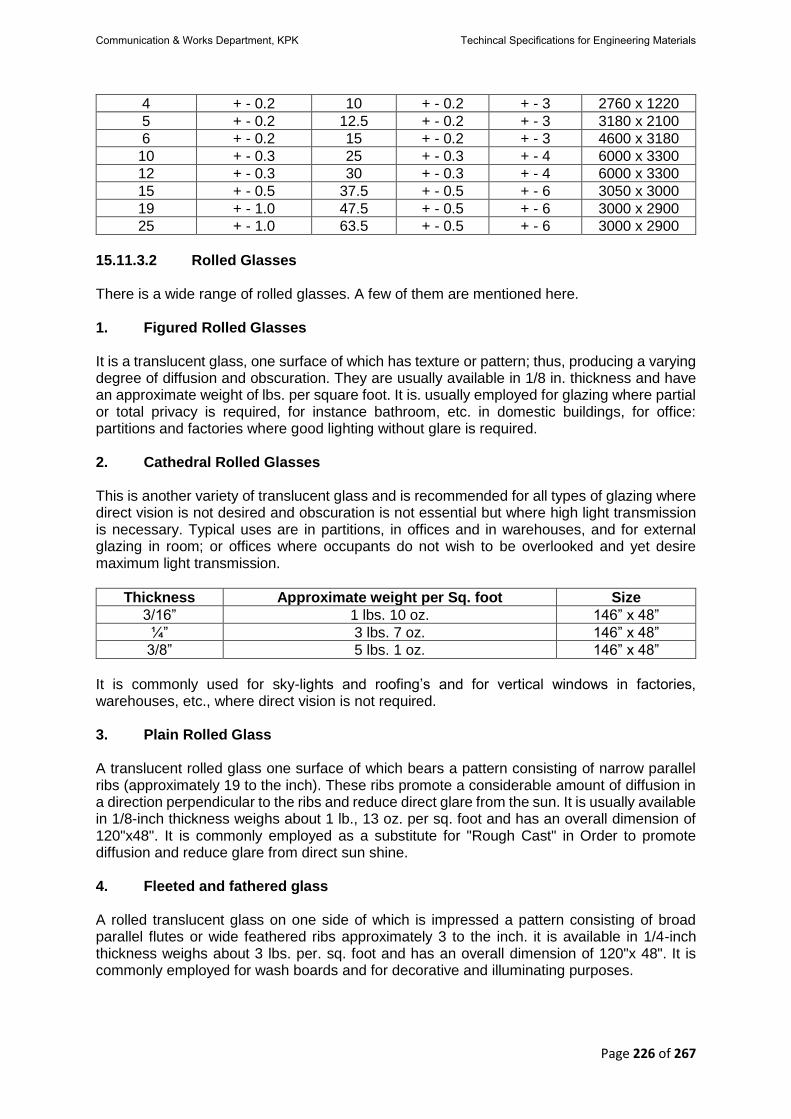
Page 226 of 267
4 + - 0.2 10 + - 0.2 + - 3 2760 x 1220
5 + - 0.2 12.5 + - 0.2 + - 3 3180 x 2100
6 + - 0.2 15 + - 0.2 + - 3 4600 x 3180
10 + - 0.3 25 + - 0.3 + - 4 6000 x 3300
12 + - 0.3 30 + - 0.3 + - 4 6000 x 3300
15 + - 0.5 37.5 + - 0.5 + - 6 3050 x 3000
19 + - 1.0 47.5 + - 0.5 + - 6 3000 x 2900
25 + - 1.0 63.5 + - 0.5 + - 6 3000 x 2900
15.11.3.2 Rolled Glasses There is a wide range of rolled glasses. A few of them are mentioned here. 1. Figured Rolled Glasses It is a translucent glass, one surface of which has texture or pattern; thus, producing a varying degree of diffusion and obscuration. They are usually available in 1/8 in. thickness and have an approximate weight of lbs. per square foot. It is. usually employed for glazing where partial or total privacy is required, for instance bathroom, etc. in domestic buildings, for office: partitions and factories where good lighting without glare is required. 2. Cathedral Rolled Glasses This is another variety of translucent glass and is recommended for all types of glazing where direct vision is not desired and obscuration is not essential but where high light transmission is necessary. Typical uses are in partitions, in offices and in warehouses, and for external glazing in room; or offices where occupants do not wish to be overlooked and yet desire maximum light transmission.
Thickness Approximate weight per Sq. foot Size
3/16” 1 lbs. 10 oz. 146” x 48”
¼” 3 lbs. 7 oz. 146” x 48”
3/8” 5 lbs. 1 oz. 146” x 48”
It is commonly used for sky-lights and roofing’s and for vertical windows in factories, warehouses, etc., where direct vision is not required. 3. Plain Rolled Glass A translucent rolled glass one surface of which bears a pattern consisting of narrow parallel ribs (approximately 19 to the inch). These ribs promote a considerable amount of diffusion in a direction perpendicular to the ribs and reduce direct glare from the sun. It is usually available in 1/8-inch thickness weighs about 1 lb., 13 oz. per sq. foot and has an overall dimension of 120"x48". It is commonly employed as a substitute for "Rough Cast" in Order to promote diffusion and reduce glare from direct sun shine. 4. Fleeted and fathered glass A rolled translucent glass on one side of which is impressed a pattern consisting of broad parallel flutes or wide feathered ribs approximately 3 to the inch. it is available in 1/4-inch thickness weighs about 3 lbs. per. sq. foot and has an overall dimension of 120"x 48". It is commonly employed for wash boards and for decorative and illuminating purposes.
Communication & Works Department, KPK Techincal Specifications for Engineering Materials

Page 227 of 267
5. Laminating glass A rolled translucent glass on one side of which is impressed a pattern consisting of parallel reeds approximately 6 to the inch. Itis usually available in 1/8-inch thickness weighs about 1 lb. 10 oz. per square foot and has an overall size of 120"x48". it is used Tor decorative and illuminating purposes. 15.11.3.3 Wired Glass A glass with a wire mesh (square or hexagonal) embedded in it during the process of rolling. It is valuable for safety purposes and has an efficient fire retardegative. it is commonly employed for glazing roof lights and lantern lights also for the vertical windows in warehouses, factories, workshops, etc. where maximum protection is needed against shocks. 1. Cast Wired Glass Translucent glass having a cast/patterned surface. 2. Polished Wired Glass Transparent glass produced by grinding and polishing cast wired glass.
3. Availability of Wired Glass Table gives the range of thicknesses and tolerances, cutting tolerances and maximum sizes normally available.
Type Nominal
Thickness Tolerance on
Thickness Cutting Tolerance Normal
Maximum Size
Sides <1500mm
Sides >1500mm
mm Mm Mm mm Mm
Cast Wired Glass
6 + 0.3 - 0.7
+ - 4 + - 4 3700 x 1840
7 + - 0.7 + - 4 + - 4 3700 x 1840
Polished Wire Glass
6 + - 1.0 + - 2 + - 3 3300 x 1830
15.11.3.4 Sheet Glass
1. Clear Sheet Glass Transparent glass manufactured by the flat drawn process. Sheet glass has natural fire finished surfaces but, because the two surfaces are never perfectly flat and parallel, there is always some distortion of vision and reflection. 2. Body Tinted Sheet Glass Transparent glass in which the whole body of the glass is tinted to give solar control properties. The glass reduces solar radiation transmission by increased absorption. Generally available are green, grey and bronze tints. For information on thickness and normal maximum sizes the
manufacturers should be consulted.
Communication & Works Department, KPK Techincal Specifications for Engineering Materials
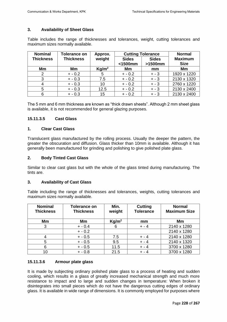
Page 228 of 267
3. Availability of Sheet Glass Table includes the range of thicknesses and tolerances, weight, cutting tolerances and maximum sizes normally available.
Nominal Thickness
Tolerance on Thickness
Approx. weight
Cutting Tolerance Normal Maximum
Size Sides
<1500mm Sides
>1500mm
Mm Mm Kg/m2 Mm mm Mm
2 + - 0.2 5 + - 0.2 + - 3 1920 x 1220
3 + - 0.3 7.5 + - 0.2 + - 3 2130 x 1320
4 + - 0.3 10 + - 0.2 + - 3 2760 x 1220
5 + - 0.3 12.5 + - 0.2 + - 3 2130 x 2400
6 + - 0.3 15 + - 0.2 + - 3 2130 x 2400
The 5 mm and 6 mm thickness are known as “thick drawn sheets”. Although 2 mm sheet glass is available, it is not recommended for general glazing purposes. 15.11.3.5 Cast Glass
1. Clear Cast Glass Translucent glass manufactured by the rolling process. Usually the deeper the pattern, the greater the obscuration and diffusion. Glass thicker than 10mm is available. Although it has generally been manufactured for grinding and polishing to give polished plate glass. 2. Body Tinted Cast Glass Similar to clear cast glass but with the whole of the glass tinted during manufacturing. The tints are. 3. Availability of Cast Glass Table including the range of thicknesses and tolerances, weights, cutting tolerances and maximum sizes normally available.
Nominal Thickness
Tolerance on Thickness
Min. weight
Cutting Tolerance
Normal Maximum Size
Mm Mm Kg/m2 mm Mm
3 + - 0.4 6 + - 4 2140 x 1280
+ - 0.2 2140 x 1280
4 + - 0.5 7.5 + - 4 2140 x 1280
5 + - 0.5 9.5 + - 4 2140 x 1320
6 + - 0.5 11.5 + - 4 3700 x 1280
10 + - 0.8 21.5 + - 4 3700 x 1280
15.11.3.6 Armour plate glass It is made by subjecting ordinary polished plate glass to a process of heating and sudden cooling, which results in a glass of greatly increased mechanical strength and much more resistance to impact and to large and sudden changes in temperature: When broken it disintegrates into small pieces which do not have the dangerous cutting edges of ordinary glass. It is available in wide range of dimensions. It is commonly employed for purposes where
Communication & Works Department, KPK Techincal Specifications for Engineering Materials

Page 229 of 267
a strong, heat resisting glass is required; for example, shelves, tablet tops, cookers, doors, display signs: electric fire, flood lighting, hospital lockers, screens, windows for mental hospitals, shops and shop fronts, trolley tops, ship's side scuttles and port lights and in many industrial applications. 15.11.3.7 Armour Light Glass This glass is obtained by a development of the armour plate glass whereby blown or pressed glass can be toughened. The degree to which an article can be toughened depends on the shape and thickness of the glass. It is commonly employed where-resistance to impact or thermal shock is necessary; for example, for roof and pavement lenses, high voltage insulation well glasses, bulk head glasses and globes, etc. 15.11.3.8 Light Refracting Glass
This is rolled glass one surface of which consists of parallel prisms which reflect the light' passing through them according to the angle of the prisms. It is also named as prismed glass. It is usually available in 1/4" thickness, weighs about 3 lbs. per sq. ft. and has an overall dimension of .100" X 48". It is commonly employed for glazing windows overshadowed by adjacent buildings. 15.11.3.9 Anti-fly Glass An amber-tinted glass designed as an effective deterrent against house flies and is valuable for use in windows of buildings connected with storage of food. Usually it is available in 1/8-inch thickness. 15.11.3.10 Anti-Gun Glass A high-quality polished plate glass which absorbs heat without reducing unduly the light transmission. It has a light greenish tint. The light transmission, factor for sun light is of the order of 72 to 80 per cent and where the glass is exposed to solar radiation about 40 to 50 per cent of the total radiation is transmitted. It is used for glazing of offices, schools, hospitals, factories, airports and control towers, etc., and in all instances where climatic. or other local conditions demand the use of a g kiss with these special characteristics. 15.11.3.11 Calorex It is a heat absorbing glass in rolled, polished or clear sheet form and absorbs about per cent of solar infrared rays. It permits the passage of about 60 per cent of visible light and has a soft greenish tint: It is employed in situations where a reduction of the transmission of the sun's radiant heat is required without undue loss of light. 15.11.3.12 Coloured Sheet Glasses These are of two types, flashed and part coloured glass. The flashed glasses are those in which, during manufacture, a thin layer of a coloured metal is imposed upon a clear sheet base metal. Part coloured glasses are those in which the colour is introduced by dyeing the glass in the mass. They are available in self colours, black, while, green, cream primrose, pearl grey, egg shell, ivory, etc. It is commonly employed for wall lighting in bath rooms, kitchens, corridors, hairdressing saloons, cinema halls. External facing of buildings, operating theatres and table tops, etc.
Communication & Works Department, KPK Techincal Specifications for Engineering Materials

Page 230 of 267
15.11.3.13 Pressed Glass The term "pressed glass" embraces pavement lights, decorative moulded panels and certain types of glass tile; etc. The glass liquid is pressed into moulds of requisite dimensions and shape. 15.11.3.14 Safety and Bulletproof Glass Laminated glass, built up of layers of glass between which are cemented layers or colorless transparent plastic resembling celluloid, is called shatterproof or safety glass. The chief use of glass of this type is in automobiles, but it is also used for sky-lights and in the windows of asylums. Bulletproof glass or bullet resisting glass is a thick safety glass used in banks. Ordinary safety glass is 1/8 to 1/4-inch-thick but bulletproof glass has several laminations built up of thicknesses to 2 inches. The thickness most commonly used is I-1 inches. This glass will not be penetrated by bullets from most firearms which might be used, but 2-inch glass is recommended to resist shots from a 303 rifle. These types of glass will crack under impact but the plastic layers hold the various pieces of glass together so that it does not shatter. 15.11.4 Work on Glass In order to cut various decorative designs on the surface of glass and to give different shades and colours the following processes are employed. 15.11.4.1 Acid Embossing or Etching It is the most Common method of working on the surface of glass and owes its existence to the property possessed by hydrofluoric acid of dissolving glass when applied to polish plate glass, the acid dissolves the surface, leaving it comparatively cleat; but, by adding an alkali such as ammonia a dense white frosted appearance is obtained. This combination of acid and alkali treatment is known as white acid and by subsequent acid treatment as many as four or five tones can be obtained, each one slightly less obscured than the last. Stippling or stippled acid finishes are obtained by strewing grains of mica evenly over the surface of glass before flooding with acid. The acid is more active where the mica has not settled on the glass and a stippled texture results, the coarseness or fineness of the stipple being determined by the size of the mica grain used. The finishes which constitute acid etching are: -
i. Single Acid—A design worked on a white acid surface with u further acid process, so that two shades are produced.
ii. Double Acid—A design worked on a white acid surface with two further acid processes; so that three shades are produced.
iii. Double or Furnish Acid—A design worked on u white acid surface with three or more acid processes, so that four or more shades are produced.
15.11.4.2 Brilliant Cutting and Edge work It is a decorative process used lit cutting design on glass surfaces. the design being cut by bringing the glass to bear on a revolving sand-stone wheel, after which it is smoothed and polished. Various standard types of cut that can be worked are: V cut, edge cut, round cut, panel-cut, round punt, oval punt and hollow or finger grip. 15.11.4.3 Edge work and Beveling These are processes whereby the cut edges are worked to produce various shapes, the most common being anises edge, flat edge, rounded edge, half round, full round, thumb or bull
Communication & Works Department, KPK Techincal Specifications for Engineering Materials

Page 231 of 267
nose. Bevel, miter bevel single side, miter bevel both sides, steep bevel and feather edge bevel. 15.11.4.4 Sandblasting Sandblasting comprises of deep sandblast, light sandblast and shaded sandblast. Each process is employed for different purposes as described below: - Deep sandblasting or grave sandblast bites deeply into the glass and can be used where a design of varying depth is required. Light sandblast gives a flat obscured effect and is applied to the whole surface of glass or in the form of lines, or in any flat decorative design. It also provides a base for painted lines or sprayed paint finishes. Shaded sandblast is a process by which a design of delicate graduation can be produced. 15.11.4.5 Silvering Any form of glass may be silvered for decorative purposes, but for mirror it is dry to use selected quality polish plate. Gunmetal or dull grey silvered mirrors are obtained by depositing a special grey alloy on polished plate glass whereas other forms of tinted mirrors are usually produced by depositing silver on tinted polished plate glass. 15.11.5 Measurement The measurement of sheet shall be in sq. feet or sq. meter having specified thickness. 15.11.6 Rate The unit rate shall be full compensation for supplying specified thickness at site of work. 15.11.7 Payment Payment shall be made under: -
Pay item Number
Description Unit
15.11.7.1 Supply of Glass for Glazing of Specified Quality and thickness.
Per sq. ft or sq. m.
15.12 Carbon Steel Bars for Concrete Reinforcement
i. This section covers deformed and plain carbon steel bars for concrete reinforcement
in cut lengths and coils. Steel bars containing alloy additions, such as with the AISI and SAE series of alloy steels, are permitted if the resulting product meets all the other requirements of this specification. The standard sizes and dimensions of deformed bars and their number designations are given in Table. The text of this specification references notes and footnotes which provide explanatory material. These notes and footnotes (excluding those in tables and figures) shall not be considered as require- Rolled Structural Steel Bars, Plates, Shapes, and Sheet ments of the specification.
ii. Bars are of three minimum yield levels: namely, 40 000 (280 Mpa), 60 000 (420 MPa), and 75 000 psi (520 MPa), designated as Grade 40 (280), Grade 60 (420), and Grade 75 (520), respectively.
iii. Hot-rolled plain rounds, in sizes up to and including 2 in. (50.8 mm) in diameter in coils or cut lengths, when specified for dowels, spirals and structural ties or supports shall be furnished under this specification in Grade 40 (280), Grade 60 [420], and Grade 75
Communication & Works Department, KPK Techincal Specifications for Engineering Materials

Page 232 of 267
[520]. For ductility properties (elongation and bending), test provisions of the nearest smaller nominal diameter deformed bar size shall apply. Requirements providing for deformations and marking shall not be applicable.
iv. This specification is applicable for orders in either inch-pound units (as Specification A 615) or in SI units (as Specification A 615M).
v. The values stated in either inch-pound units or SI units are to be regarded as standard. Within the text, the SI units are shown in brackets. The values stated in each system are not exact equivalents; therefore, each system must be used independently of the other. Combining values from the two systems may result in nonconformance with the specification.
Ba
r d
es
ign
ati
on
No
.
No
min
al W
t. l
b./ft
(no
min
al m
as
s k
g/m
) Nominal Dimension
Deformation Requirements, in.
(mm)
Diameter, in (mm)
Cross-section area, in.2 (mm)
Perimeter, in. (mm)
Max. Average spacing
Min. average height
Max. gap (Chord of 12.5% of nominal perimeter)
3[10] 0.376 [0.560]
0.375 [9.5]
0.11 [71]
1.178 [29.9]
0.262 [6.7]
0.015 [0.38]
0.143 [3.6]
4[13] 0.668 [0.994]
0.500 [12.7]
0.20 [129]
1.571 [39.9]
0.350 [8.9]
0.020 [0.51]
0.191 [4.9]
5[16] 1.043 [1.552]
0.625 [15.9]
0.31 [199]
1.963 [49.9]
0.437 [11.1]
0.028 [0.71]
0.239 [6.1]
6 [19]
1.502 [2.235]
0.750 [19.1]
0.44 [284]
2.356 [59.8]
0.525 [13.3]
0.038 [0.97]
0.286 [7.3]
7 [22]
2.044 [3.042]
0.875 [22.2]
0.60 [387]
2.749 [69.8]
0.612 [15.5]
0.044 [1.12]
0.334 [8.5]
8 [25]
2.670 [3.973]
1.000 [25.4]
0.79 [510]
3.142 [79.8]
0.700 [17.8]
0.050 [1.27]
0.383 [9.7]
9 [29]
3.400 [5.0601]
1.128 [28.7]
1.00 [645]
3.544 [90.0]
0.790 [20.1]
0.056 [1.42]
0.431 [10.9]
10 [32]
4.303 [6.404]
1.270 [32.3]
1.27 [819]
3.990 [101.3]
0.889 [22.6]
0.064 [1.63]
0.487 [12.4]
11 [36]
5.313 [7.907]
1.410 [35.8]
1.56 [1006]
4.430 [112.5]
0.987 [25.1]
0.071 [1.80]
0.540 [13.7]
14 [43]
7.65 [11.38]
1.693 [43.0]
2.25 [1452]
5.32 [135.1]
1.185 [30.1]
0.085 [2.16]
0.648 [16.5]
18 [57]
13.60 [20.24]
2.257 [57.3]
4.00 [2581]
7.09 [180.11
1.58 [40.1]
0.102 [2.59]
0.864 [21.9]
15.12.1 Terminology
Deformed Bar: Steel bar with protrusions; a bar that is intended for use
as reinforcement in reinforced concrete construction.
Discussion: The surface of the bar is provided with lugs or
protrusions that inhibit longitudinal movement of the bar relative to the concrete surrounding the bar in such construction. The lugs or protusions conform to the provisions of this specification.
Communication & Works Department, KPK Techincal Specifications for Engineering Materials

Page 233 of 267
Deformations: Protrusions on a deformed bar. Plain Bar: Steel bar without protrusions. Rib: Longitudinal protrusions on a deformed bar. 15.12.2 Ordering Information It shall be the responsibility of the purchaser to specify all requirements that are necessary for material ordered to this specification. Such requirements shall include but are not limited to the following: -
i. Quantity (Weight (mass), ii. Name of the material (deformed and plain carbon steel bars for concrete
reinforcement iii. Size iv. Cut lengths or coils, v. Deformed or plain vi. Grade vii. Packaging viii. ASTM designation and year of issue, and ix. Certified mill test report (if desired).
15.12.3 Material and Manufacture The bars shall be rolled from properly identified heat of mold cast or strand cast steel using the electric-furnace, basic-oxygen, or open-hearth process. 15.12.4 Chemical Composition An analysis of each heat of steel shall be made by the manufacturer from test samples taken preferably during the pouring of the heats. The percentages of carbon, manganese, phosphorus, and sulfur, shall be determined. The phosphorus content thus determined shall not exceed 0.06%. A product check, for phosphorus, made by the purchaser shall not exceed that specified in 15.12.4 of these specifications by more than 25%. 15.12.5 Requirements for Deformations
Deformations shall be spaced along the bar at substantially uniform distances. The deformations on opposite sides of the bar shall be similar in size, shape, and pattern. The deformations shall be placed with respect to the axis of the bar so that the included angle is not less than 45°. Where the line of deformations forms an included angle with the axis of the bar from 45 to 70° inclusive, the deformations shall alternately reverse in direction on each side, or those on one side shall be reversed in direction from those on the opposite side. Where the line of deformations is over 70°, a reversal in direction shall not be required. The average spacing or distance between deformations on each side of the bar shall not exceed seven tenths of the nominal diameter of the bar. The overall length of deformations shall be such that the gap (measured as a chord) between the ends of the deformations on opposite sides of the bar shall not exceed 12½ % of the nominal perimeter of the bar. Where the ends terminate in a longitudinal rib, the width of the longitudinal rib shall be considered the gap. Where more than two longitudinal ribs are involved, the total width of all longitudinal ribs shall not exceed 25 % of the nominal perimeter of the bar; furthermore, the summation of gaps shall not exceed 25 % of the nominal perimeter of the bar. The nominal perimeter of the bar shall be 3.1416 times the nominal diameter. The spacing, height, and gap of deformations shall conform to the requirements prescribed in 15.12 (v).
Communication & Works Department, KPK Techincal Specifications for Engineering Materials

Page 234 of 267
15.12.6 Measurement of Deformations The average spacing of deformations shall be determined by measuring the length of a minimum of 10 spaces and dividing that length by the number of spaces included in the measurement. The measurement shall begin from a point on a deformation at the beginning of the first space to a corresponding point on a deformation after the last included space. Spacing measurements shall not be made over a bar area containing bar marking symbols involving letters or numbers. The average height of deformations shall be determined from measurements made on not less than two typical deformations. Determinations shall be based on three measurements per deformation, one at the center of the overall length and the other two at the quarter points of the overall length. Insufficient height, insufficient circumferential coverage, or excessive spacing of deformations shall not constitute cause for rejection unless it has been clearly established by determinations on each lot tested that typical deformation height, gap, or spacing do not conform to the minimum requirements prescribed in Section 15.12.6. No rejection shall be made on the basis of measurements if fewer than ten adjacent deformations on each side of the bar are measured. 15.12.7 Tensile Requirements The material, as represented by the test specimens, shall conform to the requirements for tensile properties prescribed in Table given below. The yield point or yield strength shall be determined by one of the following methods: -
a) The yield point shall be determined by drop of the beam or halt in the gage of the testing machine.
b) Where the steel tested does not have a well-defined yield point, the yield strength shall be determined by reading the stress corresponding to the prescribed strain using an autographic diagram method or an extensometer as described in ASTM Test Methods and Definitions A 370. The strain shall be 0.5% of gage length for Grade-40 (280) and Grade 60 (420) and shall be 0.35% of gage length for Grade 75 (520). When material is furnished in coils, the test sample shall be straightened prior to placing it in the jaws of the tensile machine. Straightening shall be done carefully to avoid formation of local sharp bends and to minimize cold work. Insufficient straightening prior to attaching the extensometer can result in lower-than-actual yield strength readings. The percentage of elongation shall be as prescribed in below table: -
Properties Grade 40 (280)
Grade 60 (420)
Grade 75 (520)
Tensile strength, min, psi (MPa)
60000 (420)
90000 (620)
100000 (690)
Yield strength, min, psi (MPa)
40000 (280)
60000 (420)
75000 (520)
Elongation in 8 in. (203.2mm) min, % Bar Designation No.
3 (10)
4, 5 (13, 16) 11 9 --
6 (19) 12 9 --
7, 8 (22, 25) 12 9 7
9, 10, 11 (29, 32, 36) -- 8 7
14, 18 (43, 57) -- 7 6
-- 7 6
Communication & Works Department, KPK Techincal Specifications for Engineering Materials

Page 235 of 267
15.12.8 Bending Requirements
The bend-test specimen shall withstand being bent around a pin without cracking on the outside radius of the bent portion. The requirements for degree of bending and size of pins are prescribed in Table. When material is furnished in coils, the test sample shall be straightened prior to placing it in the bend tester. The bend test shall be made on specimens of sufficient length to ensure free bending and with apparatus which provides: -
a) Continuous and uniform application of force throughout the duration of the bending operation.
b) Unrestricted movement of the specimen at points of contact with the apparatus and bending around a pin free to rotate.
c) It is permissible to use more severe methods of bend testing, such as placing a specimen across two pins free to rotate and applying the bending force with a fixed pin. When failures occur under more severe methods, retests shall be permitted under the bend-test method prescribed in Section 15.12.9.
Bar Designation No. Pin Diameter for 180o Bend Tests
3, 4, 5 (10, 13, 16) 3 dA
6, 7, 8 (19, 22, 25) 4 d
9, 10, 11 (29, 32, 36) 6 d
14, 18 (43, 57) 8 d A d = nominal diameter of specimen.
15.12.9 Permissible Variation in Weight (Mass) Deformed reinforcing bars shall be evaluated on the basis of nominal weight (mass). The weight (mass) determined using the measured weight (mass) of the test specimen and rounding in accordance with Practice E 29, shall be at least 94% of the applicable weight (mass) per unit length prescribed in table of 15.12 (v). In no case shall overweight (excess mass) of any deformed bar be the cause for rejection. Weight (mass) variation for plain rounds shall be computed on the basis of permissible variation in diameter. For plain bars smaller than 3/8 inch (9.5mm), use Specification ASTM A510 (Specification ASTM A 510M). For larger bars up to and including 2 inches (50.8mm), use Specification ASTM A6/A6M. 15.12.10 Finish
a) The bars shall be free of detrimental surface imperfections. b) Rust, seams, surface irregularities, or mill scale shall not be cause for rejection,
provided the weight, dimensions, cross-sectional area, and tensile properties of a hand wire brushed test specimen are not less than the requirements of this specification.
c) Surface imperfections or flaws other than those specified in 15.12.11(b) shall be considered detrimental when specimens containing such imperfections fail to conform to either tensile or bending requirements. Examples include, but are not limited to, laps, seams, scabs, slivers, cooling or casting cracks, and mill or guide marks.
Bar Designation No. Pin Diameter for Bend Tests
Grade 40 (280) Grade 60 (420) Grade 75 (520)
3, 4, 5 (10, 13, 16) 3½ d 3½ d --
6 (19) 5 d 5 d 5 d
7, 8 (22, 25) -- 5 d 5 d
9, 10, 11 (29, 32, 36) -- 7 d 7 d
14, 18 (43, 57) -- 9 d 9 d
Communication & Works Department, KPK Techincal Specifications for Engineering Materials

Page 236 of 267
d = nominal diameter of the bar being bent. 15.12.11 Number of Tests
a) For bar sizes No.3 to 11 (10 to 36) inclusive, one tension test and one bend test shall
be made of the largest size rolled from each heat. If, however, material from one heat differs by three or more designation numbers, one tension and one bend test shall be made from both the highest and lowest designation number of the deformed bars rolled.
b) For bar sizes Nos. 14 and 18 (43 and 57), one tension test and one bend test shall be made of each size rolled from each heat.
c) For all bar sizes one set of dimensional property tests including bar weight (mass) and spacing, height, and gap of including bar weight (mass) and spacing, height, and gap of deformations shall be made of each bar size rolled from each heat.
15.12.12 Retests
a) If any tensile property of any tension test specimen is less than that specified, and any
part of the fracture is outside then middle third the gage length, as indicated by scribe scratches marked on the specimen before testing, a retest shall be allowed.
b) If the results of an original tension specimen fail to meet the specified minimum requirements and are within 2000 psi (14 MPa) of the required tensile strength, within 1000 psi (7 MPa) of the required yield point, or within two percentage units of the required elongation, a retest shall be permitted on two random specimens for each original tension specimen failure from the lot. Both retest specimens shall meet the requirements of this specification.
c) If a bend test fails for reasons other than mechanical reasons or flaws in the specimen as described in 14.5 and 14.6, a retest shall be permitted on two random specimens from the same lot. Both retest specimens shall meet the requirements of this specification. The retest shall be performed on test specimens that are at air temperature but not less than 60oF (16oC).
d) If a weight (mass) test fails for reasons other than flaws in the specimen as described in 14.6, a retest shall be permitted on two random specimens from the same lot. Both retest specimens shall meet the requirements of this specification.
e) If any test specimen fails because of mechanical reasons such as failure of testing equipment or improper specimen preparation, a replacement specimen shall be permitted.
f) If flaws are detected in a test specimen, either before or during the performance of the test, a replacement specimen shall be permitted from the same heat and bar size as the original.
15.12.13 Test Specimens
a) All mechanical tests shall be conducted in accordance with Test Methods and
Definitions ASTM A 370 including Annex A9. b) Tension test specimens shall be the full section of the bar as rolled. The unit stress
determination shall be based on the nominal bar area. c) The bend-test specimens shall be the full section of the bar as rolled.
15.12.14 Test Reports
a) When specified in the purchase order, the following information shall be reported on a
per heat basis. Report additional items as requested or desired. b) Chemical analysis including carbon, manganese, phosphorous, and sulfur.
Communication & Works Department, KPK Techincal Specifications for Engineering Materials

Page 237 of 267
c) Tensile properties. d) Bend test.
15.12.15 Inspection The inspector representing the purchaser shall have free entry, at all times while work on the contract of the purchaser is being performed, to all parts of the manufacturer’s works that concern the manufacture of the material ordered. The manufacturer shall afford the inspector all responsible facilities to satisfy him that the material is being furnished in accordance with this specification. All tests (except product analysis) and inspection, shall be made at the place of manufacture prior to shipment, unless otherwise specified, and shall be so conducted as not to interfere unnecessarily with the operation of the work. 15.12.16 For Government Procurement Only Except as otherwise specified in the contract, the contractor is responsible for the performance of all inspection and test requirements specified herein. The contractor shall be permitted to use his own or any other suitable facilities for the performance of the inspection and test requirements specified herein, unless disapproved by the purchaser at the time of purchase. The purchaser shall have the right to perform any of the inspections and tests at the same frequency as set forth in this specification, where such inspections are deemed necessary to ensure that material conforms to prescribed requirements. 15.12.17 Rejection
a) Unless otherwise specified, any rejection based on tests made in accordance with
15.12.18, shall be reported to the manufacturer within five working days from the receipt of samples by the purchaser.
b) Material that shows injurious defects subsequent to its acceptance at the manufacturer’s works will be rejected, and the manufacturer shall be notified.
15.12.18 Rehearing
Samples tested in accordance with 15.12.18 that represent rejected material shall be preserved for two weeks from the date rejection is reported to the manufacturer. In case of dissatisfaction with the results of the tests, the manufacturer shall have the right to make claim for a rehearing within that time. 15.12.19 Marking
a) When loaded for mill shipment, bars shall be properly separated and tagged with the manufacturer’s heat or test identification number.
b) Each producer shall identify the symbols of his marking system. c) All bars produced to this specification, except plain round bars which shall be tagged
for grade, shall be identified by a distinguishing set of marks legibly rolled onto the surface of one side of the bar to denote in the following order: -
15.12.19.1 Point of Origin Letter or symbol established as the producer’s mill designation. 15.12.19.2 Size Designation
Arabic number corresponding to bar designation number given in table of 15.12 (b).
Communication & Works Department, KPK Techincal Specifications for Engineering Materials

Page 238 of 267
15.12.19.3 Type of Steel Letter S indicating that the bar was produced to this specification, or for Grade 60 (420) bars only, letters S and W indicating that the bar was produced to meet both Specification ASTM A615/A615M and A706/A706M. 15.12.19.4 Minimum Yield Designation
a) For Grade 60 (420) bars, either the number 60 (4) or a single continuous longitudinal line through at least five spaces offset from the center of the bar side. For Grade 75 (520) bars, either the number 75 (5) or two continuous longitudinal lines through at least five spaces offset each direction from the center of the bar. (No marking designation for grade 40 (280) bars.)
b) It shall be permissible to substitute: a metric size bar of Grad 280 for the corresponding inch-pound size bar of Grade 75, 520 for the corresponding inch-pound size bar of Grade 75.
15.12.20 Packaging When specified in the purchase order, packaging shall be in accordance with the procedures in Practice ASTM A700. 15.12.21 Measurement The steel products shall unless otherwise specified be measured by weight. The unit of measurement shall be one Ton. 15.12.22 Rate and Payment The unit rate shall include furnishing steel products conforming to above specifications at site of work to be cleaned in the conditions of Contract. Payment shall be made under: -
Pay item Number
Description Unit
15.12.22.1 Supply of Steel for Concrete Reinforcement of specified quality.
Per 100 kg
15.13 High Strength Steel Bars for Pre-Stressing Concrete
a) This specification covers uncoated high-strength steel bars intended for use in
pretensioned and post-tensioned prestressed concrete construction or in prestressed ground anchors. Bars are of a minimum ultimate tensile strength level of 1035 Mpa (15000 psi).
b) Two types of bars are provided: Type I bar has a plain surface and Type II bar has surface deformations.
c) Supplementary requirements of an optional nature are provided. They shall apply only when specified by the purchaser.
d) The values stated in SI units are to be regarded as the standard. The values given in parentheses are for information only.
15.13.1 Reference Documents
a) A 370 Test Methods and Definitions for Mechanical Testing of Steel Products
Communication & Works Department, KPK Techincal Specifications for Engineering Materials

Page 239 of 267
b) A 700 Practices for Packaging Marking, and Loading Methods for Steel Products for Domestic Shipment.
c) ASTM E350-18 for Chemical Analysis of Carbon Steel, Low-Alloy Steel, Silicon Electrical Steel, Ingot Iron, and Wrought Iron
15.13.2 Ordering Information Orders for material under this specification should include the following information: -
a) Quantity b) Name of material (uncoated high-strength bars for prestressing concrete), c) ASTM designation and year of issue, d) Size and length, e) Type, f) Special inspection requirements, if desired g) Special preparation for delivery, if desired h) Supplementary requirements, if desired.
15.13.3 Material & Manufacture
a) The bars shall be rolled from properly identified heats of ingot cast or strand cast steel.
The standard sizes and dimensions of Type I and II bars shall be those listed in Table of 15.13.5, respectively.
b) The bars shall be subjected to cold-stressing to not less than 80% of the minimum ultimate strength, and then shall be stress relieved, to produce the prescribed mechanical properties.
15.13.4 Chemical Composition
a) An analysis of each heat of steel shall be made by the manufacture from test sample
taken during the pouring of each heat. b) Choice and use of chemical composition and alloying elements, to produce the
mechanical properties of the finished bar prescribed in Section 15.13.5, shall be made by the manufacturer, subject to the limitations given in 15.13.4 (c).
c) On heat analysis, phosphorus and sulfur shall not exceed the following: - Phosphorus 0.040% Sulphur 0.050%
d) A product analysis may be made by the purchaser from the finished bar representing each cast or heat of steel. The phosphorus and sulfur contents thus determined shall not exceed the limits specified in 15.13.4 (c) by 0.008%.
15.13.5 Mechanical Properties All testing for mechanical properties shall be performed in accordance with the requirements of Test Methods and Definitions ASTM A 370.
Nominal Diameter Nominal Mass (weight) Nominal Area
Mm in. Kg/m Ib./ft mm2
In.2
19 ¾ 2.23 1.50 284 0.44
22 7/8 3.04 2.04 387 0.60
25 1 3.97 2.67 503 0.78
29 1-1/8 5.03 3.38 639 0.99
Communication & Works Department, KPK Techincal Specifications for Engineering Materials

Page 240 of 267
32 1¼ 6.21 4.17 794 1.23
35 1-3/8 7.52 5.05 955 1.48
Nominal Diameter Nominal Mass (weight) Nominal Area
Mm in. Kg/m Ib./ft mm2
In.2
15 5/8 1.46 0.98 181 0.28
20 ¾ 2.22 1.49 271 0.42
26 1 4.48 3.01 584 0.85
32 1¼ 6.54 4.39 806 1.25
36 1 3/8 8.28 5.56 1019 1.58
46 1 ¾ 13.54 9.10 1664 2.58
65 2½ 27.10 18.20 3331 5.16
15.13.6 Tensile Properties
a) Finished bars shall have a minimum ultimate tensile strength of 1035 MPa (15000 psi). b) The minimum yield strength of Type I and Type II bars shall be 85% and 80%,
respectively, of the minimum ultimate tensile strength of the bars. The yield strength shall be determined by either of the methods described in Test Methods and Definitions A 370; however, in the extension under load method, the total strain shall 0.7%, and in the offset method the offset shall be 0.2%.
c) The minimum elongation after rupture shall be 4.0% in a gage length equal to 20 bar diameters, or 7.0% in a gage length equal to 10 bar diameters.
d) Tension tests shall be made using full-size bar test specimens. Machined reduced section test specimens are no permitted. All unit stress determinations shall be based on the nominal area or the effective area as shown in tables of 15.13.5 given above.
15.13.7 Number of Tests The number of tensile specimens tested shall be one from each 36 Mg (39 tons) or fraction thereof, of each size of bar rolled from each heat but not less than two from each heat. The specimens shall be randomly selected following the final processing operation. 15.13.8 Retests
a) If any tensile property of any tension test specimen is less than that specified, and any
part of the fracture is outside the middle third as indicated by scratched marked on the specimen before testing, a retest shall be allowed.
b) If the results of an original tension test fail to meet specified requirements, two additional tests shall be made on samples of bar from the same heat and bar size, and if failure occurs in either of these tests, the bar size from that heat shall be rejected.
c) If any test specimen fails because of mechanical reasons such as failure of testing equipment, it shall be discarded and another specimen taken.
d) If any test specimen develops flaws, it shall be discarded and another specimen of the same size bar from the same heat substituted.
15.13.9 Requirements for Deformations
a) Material furnished as Type II bar shall have deformations spaced uniformly along the
length of the bar. The deformations on opposite sides of the bar shall be similar in size and shape. The average spacing or distance between deformations on both sides of the bar shall not exceed seven tenths of the nominal diameter of the bar.
Communication & Works Department, KPK Techincal Specifications for Engineering Materials

Page 241 of 267
b) The minimum height and minimum projected area of the deformations shall conform to the requirements shown in Table of 15.13.10
c) Mechanical Coupling- For those bars having deformations arranged in a manner to permit coupling of the bars with a screw-on type coupler, it shall be the responsibility of the finished-bar manufacture to demonstrate that a bar cut at any point along its length may be coupled to any other length of bar and that a coupled joint supports the minimum specified ultimate tensile strength of the coupled bars. The coupler type shall be provided or designed by the finished-bar manufacture.
15.13.10 Measurements of Deformations
a) The average spacing of deformations shall be determined by dividing a measured
length of the bar specimen by the number of individual deformations and fractional parts of deformations on any one side of the bar specimen. A measured length of the bar specimen shall be considered the distance from a point on deformation to a corresponding point on any other deformation on the same side of the bar.
b) The average height of deformations shall be determined from measurements made on not less than the typical deformations. Determinations shall be based on three measurements per deformation: one at the center of the overall length, and the other at the quarter points of the overall length.
c) To indicate adequately the conformity to the dimensional requirement, measurements shall be taken at random from one bar from each 30 Mg (33 tons) of each lot or fraction thereof.
Deformation Dimensions
Nominal Diameter
Maximum Average Spacing
Minimum Average Height
Minimum Projected
AreaA
Mm in. Mm in. mm in. mm2
/ mm. in.2
/in.
15 5/8 11.1 0.44 0.7 0.03 2.4 0.09
20 ¾ 13.3 0.52 1.0 0.04 3.4 0.13
26 1 17.8 0.70 1.3 0.05 4.4 0.17
32 1¼ 22.5 0.89 1.6 0.06 5.4 0.21
36 1-3/8 25.1 0.99 1.8 0.07 6.1 0.24
46 1¾ 30.1 1.19 2.2 0.09 7.3 0.29
65 2½ 44.5 1.75 2.9 0.11 9.7 0.38
d) Insufficient height, insufficient projected area, or excessive spacing of deformations
shall not constitute cause for rejection unless it has been clearly established by determinations on each on that typical deformation height or spacing does not conform to the minimum requirements prescribed in Section 15.13.9. No rejection shall be made on the basis of measurements if fewer than ten adjacent deformations on each side of the bar are measured.
15.13.11 Permissible Variation in Size or Weight
a) For Type I bars, the permissible variations from the nominal diameter specified in table
of 15.13.5 shall not exceed +0.75-0.25 mm (+0.030, -0.010 in.). b) For Type II bars, the permissible variation from the nominal weight specified in Table
of 15.13.5 shall not exceeded +3%, - 2%.
Communication & Works Department, KPK Techincal Specifications for Engineering Materials

Page 242 of 267
15.13.12 Finish The bars shall be free of defects injurious to the mechanical properties and shall have a workmanlike finish. 15.13.13 Delivery
a) Unless otherwise specified in the contract or purchase order, bars shall be packed for delivery in accordance with the finished-bar manufacturer’s standard commercial practice.
b) When specified in the contract or purchase order, bars shall be packed in accordance with Practices A 700.
1. Marking
a) Unless otherwise specified in the contract or purchase order, bars shall be sorted by size and each bundle or lift shall be properly tagged showing heat number, size, specification number (ASTM A 722), and the name of the finished-bar manufacturer in order to assure proper identification. The tags shall display the following statement, “High-Strength Prestressing Bars”. The tags shall be made of durable material and marked in legible manner with waterproof markings; not less than one tag per bundle or lift, attached by wire. In addition, both ends of each bar shall be painted yellow.
b) When specified in the contract or purchase order, bars shall be marked in accordance with ASTM Practices A 700.
15.13.14 Inspection
a) The inspector representing the purchaser shall have free entry, at all times while work
on the contract of the purchaser is being performed, to all parts of the manufacturer’s works that concern the manufacture of the material ordered. The manufacturer shall afford the inspector all reasonable facilities to satisfy him that the material is being furnished in accordance with this specification. All test (except product analysis) and inspection, shall be made at the place of manufacture prior to shipment, unless otherwise specified, and shall be so conducted as not to interfere unnecessarily with the operation of the works.
b) If specified in the purchase order, the purchaser shall reserve the right to perform any of the inspection set forth in the specification where such inspections are deemed necessary to assure that the material furnished conforms to prescribed requirements.
c) If outside inspection is waived, the finished-bar manufacturer’s certification that the material has been tested in accordance with, and meets the requirements of, this specification, shall be the basis of acceptance of the material.
15.13.15 Rejection
a) Unless otherwise specified, any rejection based on tests made in accordance with Section 15.13.5 of these specifications shall be reported to the manufacturer within 5 working days from the receipt of samples by the purchaser.
b) Material that shows injurious defects subsequent to its acceptance at the manufacturer’s works shall be subject to rejection, and the manufacturer shall be notified.
15.13.16 Rehearing Samples tested in accordance with Section 15.13.5 of these specifications that represent rejected material shall be preserved for two weeks from the date rejection is reported to the
Communication & Works Department, KPK Techincal Specifications for Engineering Materials

Page 243 of 267
manufacturer. In case of dissatisfaction with the results of the test, the manufacturer shall be permitted to make claim for a rehearing within that time. 15.13.17 Certification
a) If outside inspection is waived, a manufacturer’s certification that the material has been
tested in accordance with and meets the requirements of this specification shall be the bases of acceptance of the material. The certification shall include the specification number, year-dated of issue, and revision letter, if any.
b) The manufacturer shall, when requested in the order, furnish a representative load-elongation curve for each size and grade of bar shipped.
c) A modulus of elasticity value of 205 GPa (29 700,000 psi) shall be used for the purpose of elongation calculation for Type II bars.
15.13.18 Bending Properties
a) The bend test specimen shall withstand being bent, at ambient temperature but in no case less than 150C (59oF), around a pin without cracking on the outside of the bent portion. The requirements for degree of bending and sizes of pins are prescribed in Table given below.
b) The bend test shall be made on full-size specimens of sufficient length to ensure free bending and with an apparatus that provides the following: -
i. Continuous and uniform application of force throughout the duration of the bending
operation. ii. Unrestricted movement of the specimen at points of contact with the apparatus and
bending around a pin free to rotate or bending about a central pin on a simple span with end supports free to rotate.
Nominal Bar Diameters Diameter of Pin for 135o
Bend Mm In.
15 5/8 d=6t
20 ¾ d=6t
26 1 d=6t
32 1¼ d=8t
36 13/8 d=8t
46 1¾ d=10t
65 2½ d=10t
iii. Close wrapping of the specimen around the pin during the bending operation.
c) Other methods of bending testing shall be permitted, but failures due to such methods
shall not constitute a basis for rejection. d) The number of bend test specimens shall be one from each 20 Mg (22 tons), or fraction
thereof, of each size of bar rolled from each heat but not less than two from each heat. The specimens shall be randomly selected following the final processing operation.
e) If a bend test fails for reasons other than mechanical reasons or flaws in the specimen as described in 15.13.8 (c) and 15.13.8 (d), a retest shall be permitted on the random specimens from the quantity of the finished bar product for each bar size. If the results of both test specimens meet the specified requirements, the bars shall be accepted. The retest shall be performed on test specimens that are at air temperature but not less than 15oC (59oF).
Communication & Works Department, KPK Techincal Specifications for Engineering Materials

Page 244 of 267
15.13.19 Reduction of Area The minimum reduction of area from the effective area shall be 20% for Type I plain bars. 15.13.20 Measurement The high strength steel shall unless otherwise specified be measured by weight. The unit of measurement shall be one Ton. 15.13.21 Rate and Payment The unit rate shall include furnishing of high strength steel conforming to above specifications at site of work to be cleaned in the conditions of Contract. Payment shall be made under: -
Pay item Number
Description Unit
15.13.21.1 Supply of High Strength Steel bars for pre-stressing Concrete of specified quality.
Per 100 kg
15.14 Uncoated Stress-Relieved Steel Wire for Prestressed Concrete
a) This specification covers two types of uncoated stress-relieved round high-carbon
steel wire commonly used in prestressed linear concrete construction, as follows: -
i. Type BA -Type BA wire is used for applications in which cold-end deformation is used for anchoring purposes (Button Anchorage), and
ii. Type WA- Type WA wire is used for applications in which ends are anchored by wedges, and no cold-end deformation of the wire is involved (Wedge Anchorage).
b) Supplement I describe low relaxation wire and relaxation testing for that product. c) The values stated in either inch-pound or SI units are to be regarded as standard.
Within the text, the inch-pound units are shown in parentheses. The values stated in each system are not exact equivalent; therefore, each system shall be used independently of the other, without combining values in any way.
15.14.1 Ordering Information Orders for stress-relieved wire under this specification should include the following information: -
a) Quantity {kg (lb.)} b) Diameter, c) Type of anchorage (BA or WA), d) Packaging, e) ASTM designation and date of issue, and f) Special requirements, if any.
15.14.2 Manufacture
1. Process The steel shall be made by the basic-oxygen, open-hearth, or electric-furnace process.
Communication & Works Department, KPK Techincal Specifications for Engineering Materials

Page 245 of 267
2. Internal Soundness A sufficient discard shall be made to ensure freedom from injurious piping and undue segregation. 3. Wire The wire shall be cold-drawn to size and suitably stress relieved after cold drawing by a continuous heat treatment to produce the prescribed mechanical properties. 15.14.3 Physical Properties 1. Tensile Strength The tensile strength of Type BA wire and Type WA wire shall conform to the requirements prescribed in Table below, and shall be determined as prescribed in Test Methods and Definitions A 370. 2. Yield Strength
a) The minimum yield strength for all wire, measured by the 1.0% extension under load method, shall not be less than 85% of the specified minimum breaking strength.
b) The extension under load shall be measured by an extensometer calibrated with the smallest division not larger than 0.0001 mm/mm (0.0001 in./in.) of gage length.
Nominal Diameter, mm (in.) Tensile Strength, min, Mpa (psi)
Type BA Type WA
4.88 (0.192) A 1725 (250 000)
4.98 (0.196) 1655 (240 000) 1725 (250 000)
6.35 (0.250) 1655 (240 000) 1655 (240 000)
7.01 (0.276) 1620 (235 000) 1620 (235 000) A This size is not commonly furnished in Type BA wire.
c) The initial load corresponding to the initial stress prescribed in Table 10 (page 158)
shall be applied to eth specimen, at which time the extensometer is attached and adjusted to a reading of 0.001 mm/mm (0.001 in./in.) of gage length. The load shall then be increased until the extensometer indicates an extension of 1%. The load for this extension shall be recorded. The stress corresponding to this load shall meet the requirements for stress at 1% extension prescribed in Table of 15.14.5.
3. Elongation The total elongation under load of all wire shall not be less than 4.0% when measured in a gage length of 250mm (10 in.). The elongation shall be determined by an extensometer which is laced on the test specimen after a load corresponding to the initial stress prescribed in Table of 15.14.5 is applied. If the fracture taken place outside of the gage length, the elongation value obtained may not be representative of the material. If the elongation so measured meets the minimum requirements specified, no further testing in indicated; but if the elongation is less than the minimum requirements, the test shall be discarded and a retest made. 15.14.4 Diameter and Permissible Variations
a) Wire meting the requirement of this specification is normally ordered in the diameters
shown in Table of 15.14.3(2)
Communication & Works Department, KPK Techincal Specifications for Engineering Materials

Page 246 of 267
b) The diameter of the wire shall not vary from the nominal diameter specified by more than + 0.05mm (0.002 in.).
c) The wire shall not be out-of-round by more than 0.05 mm (0.002 in.). 15.14.5 Workmanship and Finish 1. Cast A wire sample having a chord length of 1524mm (60 in.) shall have an offset at the center of the chord of not more than 76mm (3 in.). This is equivalent to a chord of an arc of a circle not less than 7.6m (25 ft) in diameter. 2. Type Ba Wire Type BA wire shall be of suitable quality to permit cold forming of buttons for anchorage. Splitting shall not be considered a cause for rejection if the button anchorage is capable of developing the minimum required tensile strength of the wire.
Nominal Diameter,
mm(in.)
Initial Stress, Mpa
(psi)
Minimum Stress at 1% Extension, Mpa (psi)
Type BA
Type WA
4.88 (0.192) 200 (29 000) A
1725 (250 000)
4.98 (0.196) 200 (29 000) 1655 (240 000) 1725 (250 000)
6.35 (0.250) 200 (29 000) 1655 (240 000) 1655 (240 000)
7.01 (0.276) 200 (29 000) 1620 (235 000) 1620 (235 000) A This size is not commonly furnished in Type BA wire.
a) The wire shall be free of kinks. b) The wire shall be furnished in firmly tied coils having a minimum inside diameter of
1219mm (48 in.). Each coil shall be of one continuous length. c) There shall be not welds or joints in the finished wire. Any welds or joints made during
manufacture to promote continuity of operations shall be removed. d) The wire shall not be oiled or greased. Slight rusting, provided it is not sufficient to
cause pits visible to the naked eye, shall not be cause for rejection. e) Temper colors which result from the stress-relieving operation are considered normal
for the finished appearance of this strand. 15.14.6 Chemical Requirements
a) Variations in manufacturing processes and equipment among wire manufacturers
necessitate the individual selection of an appropriate chemical composition at the discretion of the manufacturer.
b) Phosphorus and sulfur values shall not exceed the following: -
Phosphorus
0.040%
Sulphur
0.050%
c) An analysis may be made by the purchaser from finished wire representing each heat
of steel. Samples for analysis shall be obtained by milling the wire in such a manner as to obtain a sample representative of the entire cross section. Prior to milling, the
Communication & Works Department, KPK Techincal Specifications for Engineering Materials

Page 247 of 267
surface shall be cleaned to remove all foreign matter. All such individual determinations shall not vary from the limit shown in 15.14.6 (b) by more than 0.008%.
15.14.7 Sampling Unless otherwise agreed upon between the manufacturer and the purchaser, one test specimen shall be taken from each 10 coils or less in a lot (Note 2) and tested to determine compliance with 15.14.3(1), 15.14.3(2), 15.14.3(3), 15.14.4 & 15.14.5(1). Note 2 – The term “lot” means all the coils of wire of the same nominal wire size contained in an individual shipping release or shipping order. 15.14.8 Inspection The purchaser shall state at the time of order whether outside inspection is required or waived. If outside inspection is required, the manufacturer shall afford the inspector representing the purchaser all reasonable facilities to satisfy him that the material is being furnished in accordance with this specification. All tests and inspections shall be made at the place of manufacture prior to shipment, unless otherwise agreed upon at the time of purchase, and shall be so conducted as not to interfere unnecessarily with the operation of the works. 15.14.9 Rejection Unless otherwise specified, any rejection based on tests made in accordance with this specification shall be reported to the manufacturer within a reasonable length of time. 15.14.10 Certification If outside inspection is waived, a manufacturer’s certification that the material has been tested in accordance with and meets the requirements of this specification shall be the basis of acceptance of the material. 15.14.11 Packaging and Marking The size of the wire, ASTM specification number, heat number, and name or mark of the manufacturer shall be marked on a tag securely attached to each bundle of wire. 15.14.12 Measurement The steel products shall unless otherwise specified be measured by weight. The unit of measurement shall be one Ton. 15.14.13 Rate and Payment The unit rate shall include furnishing steel products conforming to above specifications at site of work to be cleaned in the conditions of Contract. Payment shall be made under: -
Pay item Number Description Unit
15.14.13.1 Supply of Steel for Concrete reinforcement of specified quality.
Per 100 Kg
Communication & Works Department, KPK Techincal Specifications for Engineering Materials

Page 248 of 267
15.15 Cement Concrete Products
15.15.1 Pre-Cast Concrete Pavers This specification covers pre-cast concrete paving units block intended for use in construction of low speed roads and industrial and other paved surfaces subjected to all categories of static and vehicular loading and pedestrian traffic. Paving blocks covered by this specification are designed to form a structural element and the surfacing of pavements, having the block-to-block joints filled so as to develop frictional interlock. 15.15.1.2 Definitions
Concrete Paving Unit Block: Concrete element fitting within a 295 mm square
coordinating space with a work size thickness not less than 60 mm.
Wearing Surface (S): Surface (s) of a paving units block designed to be laid
uppermost and to be trafficked in use. Plan Area: Area bounded by those faces that are approximately
normal to the wearing surface. Compressive Strength: Average crushing strength of a sample of 16 paving unit
blocks when tested. Work Size: A size of paver, normally expressed in terms of
dimensions of length, width and thickness, specified by its manufacture to which its actual size should conform within specified deviations.
15.15.1.3 Materials Binders and Binder Constituent
1. Cement Paving unit blocks shall be made using cement complying with the requirements of the Section 3.3 of these specifications. 2. Aggregates Paving blocks shall be made using one or more of the following aggregates complying with the relevant Section of these specifications: - Fine Aggregate Section 6.4 Course Aggregate Section 6.5 3. Water The water shall be of drinking quality and shall conform to Section 2 of these specifications. 4. Admixture and Pigments Proprietary accelerating, retarding and water reducing agents shall comply with BS 5075: Part-1. Pigments shall comply with BS 1014. Calcium chloride shall comply with BS 3587.
Communication & Works Department, KPK Techincal Specifications for Engineering Materials

Page 249 of 267
15.15.1.4 Finishes The finish should be agreed between the manufacturer and the specifier. Concrete described as natural colour shall contain no pigment. In composite paving blocks the surface layer shall be formed as an integral part of the block and shall be not less than 5 mm thick. 15.15.1.5 Cement Content The cement content of the compacted concrete shall be not less than 380 kg/m3. 15.15.1.6 Sizes Shape and Tolerances 1. Size Shape Paving unit blocks shall have a work size thickness length and shape mentioned in bill of quintiles of the contract. A chamfer around the wearing surface with a work size not exceeding 7 mm in width or depth shall be permitted. All arises shall be of uniform shape. 2. Tolerance The maximum dimensional deviations from the stated work sizes for paving blocks measured in accordance with A.1 shall be as follows: - Length ± 2mm Width ± 2mm Thickness ± 3mm For paving blocks assessed each side shall be perpendicular to the wearing surface and the opposite face. NOTE. A side is considered to be perpendicular to the block faces if the difference between the two readings measured does not exceed 2 mm. Where a paving block includes profiled sides, the profile shall not deviate from the manufacturer’s specification by more than 2 mm. 15.15.1.7 Compressive Strength The compressive strength of paving unit blocks, shall be not less than 49 N/mm2 (7110 Psi) and the crushing strength of any individual unit block shall be not less than 40 N/mm2 (5800 Psi). However, if the average crushing strength of the first four units’ blocks tested is not less than 54 N/mm2 (7830 Psi) and if none of these four units’ blocks has a crushing strength of less than 40/mm2 (5800 Psi) the consignment shall be considered to comply with this specification. 15.15.1.8 Sampling
The following sampling procedure shall be used for the compressive strength test.
a) Before laying paving unit blocks, divide each designated section, comprising not more than 5000-unit blocks, in a consignment into eight approximately equal group. Clearly mark all samples at the time of sampling in such a way that the designated section or part thereof and the consignment represented by the sample are clearly defined. Take two blocks from each group.
b) Dispatch the sample to the test laboratory, taking precautions to avoid damage to the paving unit blocks in transit. Each sample shall be accompanied by a certificate from the person responsible for taking the sample stating that sampling was carried out in accordance with subsection 15.15.2.7(b) of these specifications.
Communication & Works Department, KPK Techincal Specifications for Engineering Materials

Page 250 of 267
c) Protect the paving unit blocks from damage and contamination until they have been tested carry out any tests as soon as possible after the sample has been taken.
15.15.1.9 Marking The following particulars relating to paving unit blocks made in accordance with this specification shall be indicated clearly on the delivery note, invoice, manufacturer’s or supplier’s certificate or brochure supplied with the consignment of unit’s blocks: -
a) The name, trade mark or other means of identification of the manufacturer. b) Type of binder constituent(s) used. c) Type of admixture (s) used.
15.15.1.10 Measurement Pavers shall be measured in number. The specified dimensions will be shown on the Plans. 15.15.1.11 Rate and Payment
The unit rate shall be full compensation for furnishing and erecting pavers in final position as shown on the Plans or required by the Engineer-in-charge. Payment shall be made under: -
Pay item Number Description Unit
15.15.1.11.1 Supply of precast concrete Pavers of specified quality and size.
Each
15.15.2 Loadbearing Concrete Masonry Units This specification covers hollow and solid concrete masonry units made from hydraulic cement, water, and mineral aggregates with or without the inclusion of units: - (1) normal weight, (2) medium weight, and (3) lightweight. These units are suitable for both loadbearing and nonloadbearing applications. 15.15.2.1 Material
Materials shall conform to following applicable specifications: - 1. Portland Cement It shall conform to Section 3.3 of these specifications. 2. Aggregate It shall conform to Section 6 of these specifications, except that grading requirements shall not necessarily apply: - a) Normal Weight Aggregates It shall conform to Section 6 of these specifications. b) Lightweight Aggregates It shall conform to Section 6 of these specifications.
Communication & Works Department, KPK Techincal Specifications for Engineering Materials

Page 251 of 267
3. Other Constituents Air-entraining agents, colouring pigments, integral water repellents, finely ground silica, and other constituents shall be previously established as suitable for use in concrete masonry units and shall conform to applicable ASTM standards or shall be shown by test or experience not to be detrimental to the durability of the concrete masonry units or any material customarily used in masonry construction. 15.15.2.2 Physical Requirements
a) At the time of delivery to the purchaser, units shall conform to the physical
requirements prescribed in 15.15.2.3 and 15.15.2.8 NOTE 2 – Higher compressive strengths than those listed in 15.15.2.8 may be specified where required by design. Consult with local suppliers to determine availability of units of higher compressive strength.
b) At the time of delivery to the purchaser, the linear shrinkage of units shall not exceed
0.065%. NOTE 3 – The purchaser is the public body or authority, association, corporation, partnership, or individual entering into a contract or agreement to purchase or install, or both, concrete masonry units. The time of delivery to the purchaser is FOB plant when the purchaser or the purchaser’s agent transports the concrete masonry units, or at the time unloaded at eth worksite if the manufacturer or the manufacturer’s agent transport the concrete masonry units. 15.15.2.3 Hollow Units Face shell thickness (tfs) and web thickness (tw) shall conform to the requirements prescribed in 15.15.2.3. NOTE 4 – Web thickness (tw) not conforming to the requirements prescribed in 15.15.2.3 may be approved, provided equivalent structural capability has been established when tested in accordance with the applicable provisions of Test Methods E 72, C 1314, E 519, or other applicable tests and the appropriate design criteria is in accordance with applicable building codes.
Nominal Width (W) of Units, in.
(mm)
Face shell
Thickness (tfs). min.
in. (mm)A
Web Thickness (tw)
WebB
min. in (mm)
Equivalent Web Thickness,
min. in./linear ftB,C
(mm/linear m)
3 (76.2 and 4 (102) ¾ (19) ¾ (19) 1-5/8 (136)
6 (152) 1 (25)D
1 (25) 2 ¼ (188)
8 (203) 1 ¼ (32)D
1 (25) 2 ¼ (188)
10 (254) 1 3/8 (35)D
1-1/8 (29) 2 ¼ (209)
1 ¼ (32)D,E
12 (305) and greater
1 ½ (38) 1-1/8 (29) 2 ¼ (209)
1 ¼ (32)D,E
Communication & Works Department, KPK Techincal Specifications for Engineering Materials

Page 252 of 267
A Average of measurements on 3 units taken at the thinnest point when measured as described in Test Methods C 140. When this standard is sued for split face units, not more than 10% of a split face shell area shall be less than shown, and the face shell thickness in this area shall be not less than ¾ in. (19.1 mm). When the units are solid grouted the 10% limit does not apply. B Average of measurements on 3 units taken at the thinnest point when measured as described in Test Methods C 140. The minimum web thickness for units with webs closer than 1 in. (25.4 mm) apart shall be ¾ in. (19.1 mm). C Sum of the measured thicknesses of all webs in the units, multiplied by 12 and divided by the length of the unit. Equivalent web thickness does not apply to the portion of the unit to be filled with grout. The length of that portion shall be deducted from the overall length of the unit for the calculation of the equivalent web thickness. D For solid grouted masonry construction, minimum face shell thickness shall be not less than 5/8 in. (16 mm). E this face shell thickness (tfs) is applicable where allowable design load is reduced in proportion to the reduction in thickness from basic face shell thicknesses shown, except that allowable design loads on solid grouted units shall not be reduced application provisions of Test Methods E72, C 1314, E519, or other applicable tests and the appropriate design criteria developed is in accordance with applicable building codes. 15.15.2.4 Solid Units The net cross-sectional area of solid units in every plane parallel to the bearing surface shall be not less than 75% of the gross cross-sectional area measured in the same plane. 15.15.2.5 End Flanges
For units having end flanges, the thickness of each flange shall not be less than the minimum face shell thickness. NOTE 5 – Flange beveled at the ends for mortar less head joint applications that will be filled with grout are exempt from this requirement. Flanges which are specially shaped for mortar less head joint applications which have been shown by testing or field experience to provide equivalent performance exempt from this requirement. 15.15.2.6 Permissible Variations in Dimensions 1. Standard Units For standard units, no overall dimension (width, height, and length) shall differ by more than ± 1/8 in. (3.2 mm) from the specified dimensions. 2. Particular Feature Units For particular feature units, dimensions shall be in accordance with the following: -
a) For molded face units, no overall dimension (width, height, and length) shall differ by more than ± 1/8 in. (3.2 mm) from the specified standard dimension. Dimensions of molded features shall be within ± 1/16 in. (1.6 mm) of the specified standard dimensions and shall be within ± 1/16 in. (1.6 mm) of the specified placement of the molded feature.
NOTE 6 – Molded features include, but are not limited to: ribs, scores, hex-shapes, and patterns.
Communication & Works Department, KPK Techincal Specifications for Engineering Materials

Page 253 of 267
b) For split-faced units, all non-split overall dimensions shall differ by not more than ± 1/8 in. (3.2 mm) from the specified standard dimension. On faces that are split, overall dimension will vary. Consult with local suppliers to determine achievable dimensional tolerances.
c) For slump units, no overall height dimension shall differ by more than ± 1/8 in. (3.2 mm) from the specified standard dimension. On faces that are slumped, overall dimensions will vary. Consult with local suppliers to determine achievable dimensional tolerances.
15.15.2.7 Finish and Appearance
a) All units shall be sound and free of cracks or other defects that interfere with the proper
placement of the unit or significantly impair the strength or permanence of the construction. Minor cracks, incidental to the usual method of manufacture or minor chipping resulting from customary methods of handling in shipment and delivery, are not grounds for rejection.
b) Where units are to be used in exposed wall construction, the face or faces that are to be exposed shall not show chips or cracks, not otherwise permitted, or other imperfections when viewed from a distance of not less than 20 ft (6.1 m) under diffused lighting.
c) Five percent of a shipment containing chips, not larger than 1 in. (25.4 mm) in any dimension, or cracks not wider than 0.02 in. (0.5 mm) and not longer than 25% of the nominal height of the unit, is permitted.
d) The color and texture of units shall be specified by the purchaser. The finished surfaces that will be exposed in place shall conform to an approved sample, consisting of not less than four units, representing the range of texture and color permitted.
e) A shipment shall not contain more than 5% of units, including broken units. 15.15.2.8 Sampling and Testing
a) The purchaser or authorized representative shall be accorded proper facilities to
inspect and sample the units at the place of manufacture from the lots ready for delivery.
b) Sample and test units in accordance with Test Methods C 140. c) Total linear drying shrinkage shall be based on tests of concrete masonry units made
with the same materials, concrete mix design, manufacturing process, and curing method, conducted in accordance with Test Method C 426 and not more than 24 months prior to delivery.
Compressive Strength, A
min, psi (Mpa) Water Absorption, max, lb/ft
3 (kg/m
3) (Average of 3 Unit)
Average net Area Weight Classification-Oven-Dry Weight of Concrete,
lb/ft3 (kg/m
3)
Average of 3 Units
Individual Unit
Lightweight, less than 105 (1680)
Medium Weight, 105 to less than 125
(1680-2000)
Normal Weight, 125 (2000) or
more
1900 (13.1) 1700 (11.7) 18 (288) 15 (240) 13 (208) A Higher compressive strength may be specified where required by design. Consult with local suppliers to determine availability of units of higher compressive strength. 15.15.2.9 Measurement Loadbearing concrete masonry Units shall be measured in number. The specified dimensions will be shown on the Plans.
Communication & Works Department, KPK Techincal Specifications for Engineering Materials

Page 254 of 267
15.15.2.10 Rate and Payment The unit rate shall be full compensation for furnishing and erecting Loadbearing concrete masonry Units in final position as shown on the Plans or required by the Engineer-in-charge. Payment shall be made under: -
Pay item Number Description Unit
15.15.2.10.1 Supply of Load bearing Concrete units of specified dimensions.
Each
15.16 Polystyrene Thermal Insulation
15.16.1 Description This specification covers the types, physical properties, and dimension of cellular polystyrene intended for use as thermal insulation for temperature from –65 to +165oF (–53.9 to +73.9oC). This specification does not cover cryogenic application. Consult the manufacturer for specific recommendations and properties in cryogenic conditions. 15.16.2 Terminology
a) Terms used in this specification are defined in Terminology ASTM C168. b) Terms used in this specification that relate to fire standards are defined in Terminology
ASTM E 176. c) RCPS – letter designations for the rigid cellular polystyrene thermal insulation
classified by this specification that identifies the product as rigid cellular polystyrene. d) PS – used in this specification to represent polystyrene in accordance with
Terminology ASTM D1600. 15.16.3 Classification This specification covers types of RCPS thermal insulations currently commercially available as described by the physical property requirements of RCPS Thermal Insulation. 15.16.4 Materials and Manufacture RCPS thermal insulation shall be formed by the expansion of polystyrene resin beads or granules in a closed mold, or by the expansion of polystyrene base resin in an extrusion process. RCPS thermal insulation shall be of uniform density and have essentially closed cell. All RCPS thermal insulation shall contain sufficient flame retardants to meet the oxygen index requirement of RCPS Thermal Insulation. 15.16.5 Physical Requirements
1. Inspection Requirements
a) The physical requirements listed in this section are defined as inspection requirements (refer to Criteria ASTM C 390).
b) All dimensional requirements are described in 15.16.7 of these specifications. c) All workmanship, finish, and appearance requirements and described in 15.16.8 of
these specifications. d) Density shall be in accordance with Table 1.
Communication & Works Department, KPK Techincal Specifications for Engineering Materials
Page 255 of 267
2. Qualification Requirements
a) The physical properties listed in this section of the specification are defined as qualification requirements (refer to Criteria ASTM C390). Thermal resistance, compressive resistance, flexural strength, water vapor permeance, water absorption, dimensional stability, and oxygen index shall be in accordance with Table 1 .
b) The mean thermal resistance of the material tested shall not be less than the minimum value identified in Table 1. The thermal resistances of individual specimens tested shall not be less than 90% of the minimum value identified in Table 1.
c) Compliance with qualification requirements shall be in accordance with Criteria ASTM C 390.
d) Table 1 describes types of RCPS thermal insulation. However, it does not cover all available products on the market. The value stated in Table 1 should not be used as design value. It is the buyer’s responsibility to specify design requirements and obtain supporting documentation from the material supplier.
3. Combustibility Characteristics RCPS thermal insulation is an organic material and is, therefore, combustible. It should not be exposed to flames or other ignition sources. The values obtained by the oxygen index test do not necessarily indicate or describe the fire risk of the materials and are used in this specification primarily to distinguish between insulations formulated with flame retardants and those not so formulated. 15.16.6 Dimensions and Permissible Variations
The materials covered by this specification are commonly available in the sizes shown in Table 2. Other sizes may be agreed upon between the supplier and the user. 1. Dimensional Tolerances Unless otherwise specified, the length tolerance shall not exceed +0.03 in./ft (+mm/m) of length; the width tolerance shall not exceed +0.06 in./ft (+5.0mm/m) of width; and the thickness tolerance shall not exceed +0.06 in./in. (+59.5mm/m) of thickness. For products less than 1.00 in. (25.4mm) in thickness, the thickness tolerance shall not exceed +0.06 in (1.5mm). 2. Edge Trueness Unless otherwise specified, RCPS thermal insulation shall be furnished with true edges. Edges shall not deviate more than 0.03 in./ft (2.5mm/m) of length or width. 3. Face Trueness RCPS thermal insulation shall not deviate from absolute trueness by more than 0.03 in./ft (2.5mm/m) of length or width. 4. Squareness RCPS thermal insulation shall not deviate from squareness by more than 0.06 in./ft (5.0mm/m) of length or width.
Communication & Works Department, KPK Techincal Specifications for Engineering Materials

Page 256 of 267
5. Ship-Lap and Tongue-And-Groove Edges
a) When specified, RCPS thermal insulation shall be furnished with either ship-lap or tongue-and-groove edges.
b) For RCPS thermal insulation manufactured with ship-lap edges, the depth of the ship-lap cut shall be one half the board thickness +0.06, -0 in. (+1.5, -0mm). The minimum width of the cut for RCPS thermal insulation less than 1.00 in. (25.4mm) thickness or greater shall be 0.50+0.06 in. (12.7+1.5mm). For RCPS thermal insulation less than 1.0 in. (25.4mm) in thickness, the minimum width of the cut shall be 0.25+0.06 in. (6.4+1.5mm). The ship-lap cut shall be made on opposite faces of the board for both length and width. The resulting joint shall be smooth and uniform.
c) For RCPS thermal insulation manufactured with tongue-and-groove edges, the tongue of one shall fit snugly into the groove of a second. The resulting joint shall be smooth and uniform.
15.16.7 Workmanship, Finish and Appearance
1. Defects RCPS thermal insulation shall have no defects that will adversely affect its service qualities. RCPS thermal insulation shall be of uniform texture and free opf foreign inclusions, broken edges and corners, slits, and objectionable odors. 2. Crushing and Depressions
a) RCPS thermal insulation shall have no crushed or depressed areas on any surface exceeding 0.13 in. (3.3mm) in depth on more than 10% of the total surface area.
b) The total number of voids on the board surface shall not exceed an average of 1 per square foot with dimensions larger than 0.13 by 0.13 by 0.13 in. (3.3 by 3.3 by 3.3mm).
15.16.8 Sampling Unless otherwise specified in the purchase order or contract, the material shall be sampled in accordance with Criteria ASTM C 390. 15.16.9 Test Methods 1. Conditioning and Aging
a) Samples shall be conditioned as required by the test method to either conditioned moisture equilibrium or conditioned moisture equilibrium, using procedures defined by ASTM Practice C870. Samples shall be held at equilibrium conditions untile they are transferred into the testing equipment. Samples to be used for density test, dimensional stability test, and water vapor transmission test shall be conditioned at 73.4±4oF (23±2oC) and 50±5% relative humidity for a minimum of 40h prior to the start of tests. Samples to be used for the compressive resistance test, oxygen index test, water absorption test, flexural strength test, and thermal resistance test shall be conditioned as specified in the applicable test procedure.
b) RCPS thermal insulations that incorporate a blowing agent other than air or pentane shall be aged for either 90 days at 140±2oF (60±1oC) or size months at 73.4±4oF (23±2oC) and 50±5% relative humidity prior to conditioning and thermal resistance testing. Air circulation shall be provided so that all surfaces of the insulation are exposed to the surrounding environmental conditions.
c) Where boards are tested with skin-in-place, this condition shall be noted in the test report.
Communication & Works Department, KPK Techincal Specifications for Engineering Materials

Page 257 of 267
2. Dimensions and Density Test in accordance with Test Method ASTM C303 or Test Method ASTM D1622. 3. Trueness and Squareness Test in accordance with Test Method ASTM C550. 4. Thermal Resistance Test in accordance with Test Method ASTM C303 or Test Method ASTM C177, C518, C1114, C1363 or ASTM Practice C1045 or Practice C1058. Test shall be conducted with a temperature differential of 40±2oF (22±1oC). In case of dispute, Test Method ASTM C177 shall be the referee method. The mean temperature for thermal resistance testing shall be 75±2oF (24±1oC) 5. Compressive Resistance Test in accordance with Test Method ASTM C165, Procedure A, at a crosshead speed of 0.1 in./min/in. of thickness (100mm/min/m) at yield or 10% deformation, whichever occurs first (with skin intact), or test in accordance with Test Method ASTM D1621. 6. Flexural Strength
a) Test in accordance with Test Method ASTM C203 Method I, Procedure A. All test specimens shall be 1.00±0.06 in. (25.4+1.5mm) or less in thickness. For samples less than or equal to 1.00±0.06 in. in thickness, cut test specimens from samples keeping both original major surfaces intact. If skins are present on only one major surface, test specimens with that surface in tension. For samples of greater thickness, trim test specimens to 1.00±0.06 in. thickness retaining one original major surface. Specimens shall be tested with the original major surface in tension. For anisotropic products run the tests for both the length and cross directions of the sample. Report the average of these two series of test as the value for flexural strength.
b) Specimens less than 1.00±0.06 in. (25.4±1.5mm) in thickness may continue to flex without specimen failure (break). In such cases, flexural strength testing shall be performed using thicker specimens and the thickness shall be noted in the test report.
7. Water Vapor Permeance Test in accordance with Test Method ASTM E96, using anhydrous calcium chloride as the desiccant at 73.4±4oF (23±2oC). 8. Water Absorption Test in accordance with Test Method ASTM C272. The immersion time shall be 24h and the test specimens shall be 12 by 12 by 1 in. (305 by 305 by 25mm). 9. Dimensional Stability Test in accordance with Test Method ASTM D2126 for 7 days (168h) using the following conditions: -
Communication & Works Department, KPK Techincal Specifications for Engineering Materials

Page 258 of 267
Temperature oF (oC) Relative Humidity, %
158 ± 4 (70 ± 2) 97 ± 3
-40 ± 6 (-40 ± 3) Ambient
10. Oxygen Index Test in accordance with Test Method ASTM D2863. 15.16.10 Measurement
The measurement of Insulation material shall be in sq. feet or sq. meter having specified thickness. 15.16.11 Rate and Payment The unit rate shall be full compensation for supplying the polystyrene thermal insulation material specified thickness at site of work. Payment shall be made under: -
Pay item Number Description Unit
15.16.11.1 Supply of Polystyrene thermal insulation of specified quality and thickness.
Sq. ft or sq. m
15.17 Polyethylene Sheeting for Construction
15.17.1 Description
This specification covers polyethylene sheeting, 250 m (0.010 inch or 10 mils) or less in thickness, intended for use in construction work. 15.17.2 Terminology The terminology used in this specification is in accordance with the definitions given in Terminology ASTM D883. 15.17.3 Materials The sheeting shall be made from polyethylene or modified polyethylene, such as an ethylene copolymer consisting of a major portion of ethylene in combination with a minor portion of some other monomer, or a mixture of polyethylene with a less amount of other polymers. 15.17.4 General Requirements 1. Appearance The sheeting shall have appearance qualities conforming with those produced by good commercial practices. It shall be as free as is commercially possible of gels, streaks, pinholes, particles of foreign matter, and undispersed raw material. There shall be no other visible defects such as blocking, holes, tears, or blisters. The edges shall be free of nicks and cuts visible to the unaided eye.
Communication & Works Department, KPK Techincal Specifications for Engineering Materials

Page 259 of 267
2. Dimensions
a) Size- The nominal thickness, width, and length of the sheeting in each roll shall be agreed upon between the buyer and the seller.
b) Thickness- The thickness at any point, when measured in accordance with 15.17.7 (7) of these specifications, shall not be less than 80% of the nominal thickness.
c) Width- The tolerance for widths of 0.3m (1 foot) or more, shall be 3.2mm (1/8") per foot of nominal width. For all widths less than 0.3 m (1 foot), the tolerance shall be 3.2mm (1/8"). Width to be measured in accordance with Section 15.17.7 (8) of these specifications.
d) Length- The length of sheeting per roll, when measured in accordance with Section 15.17.7 (8) of these specifications, shall be within +3% to –1% of the length specified.
3. Minimum Net Weight The actual net weight of each roll shall be not less than the nominal net weight, when determined in accordance with the formula established in Section 15.17.7 (9) of these specifications. The nominal net weight shall, in turn, be the labelled net weight. 15.17.5 Detail Requirements 1. Colour and Finish The sheeting may be natural, (essentially colorless), colour tinted, translucent, or opaque. The surface finish may be plain, printed, or otherwise treated as agree upon between the buyer and the seller. 2. Impact Resistance The average impact resistance shall be not less than the resistance specified in 15.17.8. 3. Mechanical Properties The average tensile strength and elongation at break for all thicknesses of sheeting shall be as specified in 15.17.8, when tested in accordance with Section 15.17.7 (10) of these specifications. 4. Reflectance The daylight reflectance of white opaque sheeting, intended for use in curing concrete, shall be not less than 70%, when determined in accordance with Section 15.17.7 (11) of these specifications. 5. Luminous Transmittance Black sheeting intended for exclusion of light and for maximum resistance to weathering shall have an average luminous transmittance not greater than 1%, when determined in accordance with Section 15.17.7 (12) of these specifications. This low level of luminous transmittance indicates a high degree of opacity. 7. Water Vapor Transmission Rate (WVTR) The average water vapor transmission shall not be greater than 22.0 g/m2 (1.40 g/100 in2) per 24 h for sheeting 25 um (1 mil) in thickness, when determined in accordance with Section
Communication & Works Department, KPK Techincal Specifications for Engineering Materials

Page 260 of 267
15.17.7 (13) of these specifications. The water vapor transmission rate is inversely proportional to the thickness. Specifications are given in 15.17.8 15.17.6 Sampling
a) Sampling for test purposes shall be taken from rolls, selected at random from the total number of rolls in each shipment or lot, in accordance with Table 5.
b) The samples for testing shall be full width and shall be cut at least three full turns, but not less than 1.5 m (5 ft), from either end of the sheeting on each roll. Normally about 2m2 (20ft2) fo sheeting is needed to carry out all the tests. All the tests shall not be selected for testing.
c) The specimens to be used for a particular test shall be cut from different parts of the sheeting sample (that is, they shall not be cut adjacent to one another), unless otherwise specified in the test.
15.17.7 Test Methods 1. General The tests given herein are intended primarily for use as production tests in conjunction with manufacturing processes and inspection methods to insure conformity of sheeting with the requirement of this specification. 2. Production Inspection and Testing During the process of manufacture, the manufacturer shall make inspections and tests in accordance with methods described by this specification. The manufacturer shall keep such essential records and other information to documents his claim that the requirements of this specification are met with a high degree of assurance. 3. Inspection The samples of sheeting shall be visually inspected to determine conformance of the sheeting with the requirement of these specifications. 4. Conditioning The test specimens shall be conditioned in accordance with Procedure A of Practice ASTM D618 and shall be tested under these conditions for referee tests or in the case of disputes. Otherwise, storage at room temperature should be adequate. 5. Thickness The thickness should be determined using Method ASTM C of Test Method ASTM 374. 7. Length and Width Measurement shall be made with a calibrated 30-m (100-ft) steel tape graduated at intervals of 1 mm (1/16 in.). The roll shall be extended to its full length on a flat surface and all creases and buckles removed, insofar as practical, without applying stresses that cause any significant flow. Measurement of length shall be rounded to the nearest centimeter (inches). Width shall be measured to the nearest 1 mm (1/16 in.) at not less than 10 locations uniformly distributed along the length of the roll, and the results shall be averaged.
Communication & Works Department, KPK Techincal Specifications for Engineering Materials

Page 261 of 267
8. Weight The actual net weight of each roll shall be calibrated equipment. The nominal net weight shall be calculated as follow: - W = T x A x D x k Where W = nominal, kg (lb), T = nominal thickness, mm (in.) A = nominal length times nominal width, mm (in.), D = density of the film as determined by Test Method ASTM D 1505, g/cm3, and k = 10-6 for converting g/cm3 to kg/mm3 (=0.03613 for converting g/cm3 to lb/in.3) 9. Impact Resistance The impact resistance shall be determined in accordance with Test Method ASTM D1709, using Method A for sheeting up to 250 µm (10 mils) in thickness. 10. Tensile Properties The tensile properties of polyethylene sheeting shall be determined in accordance with Method A of Test Method ASTM 882, using ten specimens for each direction. The thickness of the specimens shall be measured in accordance with Section 15.17.7 (5) of these specifications. 11. Reflectance Determine the daylight reflectance of the specimens in accordance with Test Method ASTM E1347. 12. Luminous Transmittance The luminous transmittance shall be determined in accordance with Specification ASTM D2103, using five test specimens. 13. Water Vapor Transmission The water vapor transmission rate shall be determined in accordance with Method ASTM E of Test Methods ASTM 96, using four specimens. 14. Heat Sealeability Measure heat sealeability in accordance with Test Methods ASTM F88, Test Method ASTM B, Dynamic Load Test. 15.17.8 Packaging and Marking 1. Marking Each package or roll shall be marked with the nominal width, length, area in square feet or square meters, thickness of the sheeting, and the nominal net weight of the package or roll. 2. Conformance Statement
a) In order that purchasers may identify product complying with all requirement of this specification, producers choosing to produce said product in conformance with this specification may include statement in conjunction with their name and address on
Communication & Works Department, KPK Techincal Specifications for Engineering Materials

Page 262 of 267
labels, invoices, sales literature, and the like. The following statement is suggested when sufficient space is available. This sheeting conforms to all of the requirements established in ASTM Specification ASTM D 4397, Polyethylene Sheeting for Construction, Industrial, and Agricultural Applications. Full responsibility for the conformance of this product is assumed by (name and address of producer or distributor).
b) The following abbreviated statement is suggested when available space on labels is insufficient for the full statement: Conforms to ASTM D 4397 (name and address of producer or distributor).
c) All packing, packaging, and marking provisions of Practice ASTM D3892 shall apply to this specification.
Table 1 Dart Drop Impact Resistance
Nominal Thickness, µm (mils) Dart Drop Impact Resistance, min g.
25 (1.0) 40
38 (1.5) 65
50 (2.0) 85
75 (3.0) 125
100 (4.0) 165
125 (5.0) 205
150 (6.0) 260
175 (7.0) 315
200 (8.0) 370
225 (9.0) 420
250 (10.0) 475
Table 2 Mechanical Properties
Lengthwise Direction Crosswise Direction
Tensile strength, min, MPa (psi) 11.7 (1700) 8.3 (1200)
Elongation, min, % 225 350
Table 3 Specification for Water Vapor Transmission Rate (WVTR)
WVTR (g/24-h- m2) max
Nominal Thickness WVTR (g/24-h- 100 in.2) max µm (mils)
22.0 25 (1) 1.40
11.0 50 (2) 0.70
7.3 75 (3) 0.47
5.5 100 (4) 0.35
4.4 125 (5) 0.28
3.7 150 (6) 0.23
3.1 175 (7) 0.20
2.8 200 (8) 0.18
2.4 225 (9) 0.16
2.2 250 (10) 0.14
Communication & Works Department, KPK Techincal Specifications for Engineering Materials

Page 263 of 267
Table 4 Specification for Permeance
Permeance (metric perms) max Nominal Thickness
Permeance (perms) max µm (mils)
0.50 25 (1) 0.76
0.25 50 (2) 0.38
0.17 75 (3) 0.25
0.12 100 (4) 0.19
0.10 125 (5) 0.15
0.084 150 (6) 0.13
0.070 175 (7) 0.11
0.063 200 (8) 0.096
0.054 225 (9) 0.082
0.050 250 (10) 0.076
Table 5 Sampling for Test Procedures
Rolls in Shipment or Lot Rolls Sampled
2 to 9 1
10 to 15 2
16 to 40 3
41 to 65 5
66 to 110 7
111 to 180 10
181 to 300 15
301 to 500 25
501 to 800 35
801 to 1300 50
15.17.9 Measurement The measurement of sheet shall be in sq. feet or sq. meter having specified thickness. 15.17.10 Rate and Payment The unit rate shall be full compensation for supplying specified thickness at site of work. Payment shall be made under: -
Pay item Number Description Unit
15.17.10.1 Polyethylene sheet of specified quality and thickness.
Sq. ft or sq. m
15.18 Asphalt Roll Roofing Felt
15.18.1 Description This specification covers asphalt roofing in sheet-form in widths agreed upon between the purchaser and the producer/supplier, composed of asphalt-saturated organic felt coated on both sides with asphalt. Class M and WS rolls are surfaced on the (exposed) weather side with mineral granules, except for any selvage. Class S rolls are surfaced with powdered talc, mica, or other fine mineral matter to prevent sticking.
Communication & Works Department, KPK Techincal Specifications for Engineering Materials
Page 264 of 267
15.18.2 Terminology Refer to Terminology ASTM D 1079 for definitions of terms used in this specification. 15.18.3 Classification 1. Class (Smooth) Rolls
a) Class (smooth) rolls shall be surfaced with fine mineral matter to prevent sticking. b) Type III Minimum net mass per unit area of roofing, 2495 g/m2(51.1 lb/100 ft2). c) Type IV Minimum net mass per unit area of roofing, 1943 g/m2(39.8 lb/100 ft2).
2. Class M (Mineral) Rolls
a) Class M (mineral) rolls shall be surfaced on the weather side with mineral granules, except for any selvage.
b) Type II Minimum net mass of granule-surface portion, 3490 g/m2 (71.5 lb./100 ft2). 3. Class WS (Wide Selvage) Rolls
a) Class WS (wide selvage) rolls shall be surfaced on the weather side with mineral granules for approximately half the width.
b) Type III Minimum net mass per unit area, 1733 g/m2(35.5 lb./100 ft2). c) Type IV Minimum net mass per unit area, 2090 g/m2 (42.8lb/100 ft2)
15.18.4 Materials and Manufacture
d) In the process of manufacture, a single thickness of dry organic felt shall first be saturated with asphalt. A coating asphalt, compounded with or without a fine mineral stabilizer insoluble in water, shall be applied to one or both sides of the sheet. Class S rolls shall be surfaced on one side with a suitable material to prevent sticking in the roll. Class M and WS rolls shall be covered on the weather side with mineral granules, except for any selvage; the reverse side shall be covered with a suitable material to prevent sticking in the roll.
e) The felt shall be roofing felt primarily composed of organic fibers. The surface of the felt shall be uniformly and relatively smooth. Upon splitting or tearing on the bias, the felt shall appear reasonably free of lumps or particles of foreign substances.
15.18.5 Physical Properties
a) Class S rolls shall conform to the breaking strength and water permeance requirements prescribed in Table 1.
b) Upon being unrolled, the finished product shall not crack at ambient temperatures above 10oC (50oF) nor be so sticky at any temperature below 60oC (140oF) as to cause tearing or material damage.
c) Class M rolls with a 102-mm (4-in.) wide selvage shall meet the lap strength requirements with Type II or Type III cement specified in Specification ASTM D 3019.
d) Pliability at 25oC (77oF) – At least eight strips out of ten from the granule-surfaced portion of the sheet shall not crack when tested in accordance with the appropriate section of Test Method ASTM D 228. The samples shall be tested using a mandrel with a radius of 12.7 mm (½ in.) for Class S roofing and 19 mm (3/4 in.) radius for Class M and WS roll roofing.
e) Behavior on Heating to 80oC (176oF) for 2 h – There shall be no more than 1.5% volatile loss; and there shall be no flowing, sagging, blistering, or absorption of the asphalt,
Communication & Works Department, KPK Techincal Specifications for Engineering Materials
Page 265 of 267
coating; and any granular surfacing shall not slide more than 2 mm (1/16 in.) when tested in accordance with the appropriate section of Test Method ASTM D228.
15.18.6 Dimensions, Mass and Permissible Variations 1. Width The material shall be put up in rolls and shall be 914 mm (36 in.) wide, ± 0.7%. Other widths agreed upon between the purchaser and the producer/supplier shall not be prohibited. 2. Selvage Class M rolls are available without a selvage, with a 51±6-mm (2±¼-in.) salvage. For Class WS rolls, the coated and granular surface portion of the weather side shall have a uniform, minimum width of 432±6 mm (17±¼-in) for the standard 914-mm (36-in.) wide sheet, or as agreed upon between the purchaser and the producer/supplier. For other Class WS roll widths, the coated and granule-surfaced portion shall have a minimum width of one half the sheet width minus 25±6 mm (1±¼-in). For Class WS rolls when the surfaced portion of the weather side exceeds the minimum width, the sheet shall be marked with a conspicuous mopping line located from the exposed weather edge a distance equal to one half the sheet width minus 25±6 mm (1±¼-in). 3. Area The average area of the rolls shall not deviate more than 1.0% from the stated areas. 4. Masses The roofing shall conform to the masses prescribed in Table 1 15.18.7 Workmanship, Finish and Appearance
a) The felt shall be thoroughly and uniformly saturated and shall show no unsaturated spots at any point upon cutting 51-mm (2-in.) wide strips at random across the entire sheet and splitting them open to their full length.
b) The surface of the weather side shall be uniform in finish and texture. For Class M and WS rolls, the mineral granules shall be uniformly distributed over the surface in a smooth layer excluding any selvage and be firmly embedded in the asphalt coating.
c) For Class M and WS rolls, the line of demarcation between the granule-surfaced portion of the weathers side and any salvage shall be straight and parallel to the edges of the sheet. For Class S rolls, or the selvage of Class M and WS rolls, any coating applied shall have applied to it a material to prevent sticking in the roll. Application of this material shall be uniform, but not so great as to hinder proper adhesion between plies.
d) The asphalt coating (if any) and material applied to the reverse side to prevent sticking shall be uniform over the entire area of the sheet.
e) The finished material shall be free of visible defects such as holes, ragged or untrue edges, breaks, cracks, tears, protuberances, and indentation.
15.18.8 Sampling and Test Methods
a) Sample the material and determine the properties enumerated in this specification in accordance with Test Methods ASTM D228. Sampling shall be from the granule-surfaced portion of Class M and WS rolls.
Communication & Works Department, KPK Techincal Specifications for Engineering Materials

Page 266 of 267
b) For Class M rolls, determine the lap strength in accordance with Specification ASTM D3019.
c) Determine the moisture content in accordance with Test Method ADTM146. d) Determine the pliability in accordance the appropriate section of Test Methods
ASTM228. e) Determine the behavior on heating in accordance with the appropriate section of Test
Method ASTM D228. f) For Class M and WS rolls, determine the granule loss by abrasion in accordance with
Test Method D4977. g) For Class S rolls, determine the water vapor transmission in accordance with Test
Methods ASTM E96, Procedure B. h) For Class S rolls, determine the breaking strength in accordance with the appropriate
section of Test Methods ASTM D146.
15.18.9 Inspection Inspection of the material shall be as agreed upon between the purchaser and the producer/supplier as part of the purchase contract. 15.18.10 Rejection and Resubmittal Failure to conform to any one of the requirements prescribed in this specification shall constitute grounds for rejection. Rejection shall be reported to the producer/supplier promptly in writing. In case of rejection, the producer/supplier promptly in writing. In case of rejection, the producer/supplier shall have the right to reinspect the rejected shipment and resubmit the lot after removal of those packages not conforming to the specified requirements. 15.18.11 Packaging and Marking The roofing felt shall be put up in rolls. The rolls shall be tightly wound and shall be securely wrapped with a substantial grade of paper completely encircling each roll and pasted at the overlap in such a manner as to prevent shifting from position. No roll shall contain more than two pieces, nor shall there be more than 3% of the rolls containing two pieces in any shipment. Unless otherwise agreed upon between the producer/supplier and the purchaser, each roll shall be plainly marked with the name and brand of the producer/supplier, the gross or net area of the roll, and the ASTM designation of the product, including class and type. 15.18.12 Measurement The measurement of Insulation material shall be in 100 sq. feet or sq. meter having specified thickness. 15.18.13 Rate and Payment The unit rate shall be full compensation for supplying specified thickness at site of work. Payment shall be made under: -
Pay item Number Description Unit
15.18.13.1 Supply of Asphalt roll roofing felt of Specified Quality.
100 sq. ft or sq. m
Communication & Works Department, KPK Techincal Specifications for Engineering Materials

Page 267 of 267
Communication & Works Department, KPK Techincal Specifications for Engineering Materials