commonwealth of pennsylvania department of transportation...
TRANSCRIPT

COMMONWEALTH OF PENNSYLVANIA
Department of Transportation
Office of Research and Special Studies
Steven A. Davis - Associate Director
Research Project No. 87-04 Fatigue Testing of Prestressed Beams
SUMMARY REPORT
by
Mark Kaczinski Ti Huang
BenT. Yen
Prepared in cooperation with the Pennsylvania Department of Transportation and the U.S. Department of Transportation, Federal Highway Administration. The contents of this report reflect the views of the authors who are responsible for the
-facts and the accuracy of the data presented herein. The contents do not necessarily reflect the official views or policies of the Pennsylvania Department of Transportation or the U. S. Department of Transportation, Federal Highway Administration. This report does not constttute a standard, specificaiton or regulation.
LEHIGH UNIVERSITY
Office of Research and Sponsored Programs
Bethlehem, Pennsylvania
July 1989
Fritz Engineering Laboratory Report No. 526.1

Table of Contents
Abstract
1. Introduction
1.1 History of Project 1.2 General Description of Bridge
2. Literature Search
2.l.Review Computational and Construction Data for the Ridley Creek Bridge
2.2.Lateral Load Distribution in Skewed Prestressed Concrete I-Beam Bridges
Page
iii
1
1 2
3
3
5
2.2.1 Lateral Load Distribution in Right Prestressed 5 Concrete I-Beam Bridges
2.2.2 Effect of Skew 5
2.3 Fatigue of Pre~tressed Concrete Beams 8
3. Pre-Test Analysis 11
3.1 Introduction 11 3.2 Analysis of Pre-Post-Tensioned Composite Beams 11 3.3 Effect of Interior Diaphragms on Load Distribution in 15
Skewed Prestressed Concrete I-Beam Bridges
3.3.1 Background 3.3.2 Objective 3.3.3 Finite Element Model 3.3.4 Loads 3.3.5 Analysis 3.3.6 Preliminary Conclusions
4. Field Testing and Beam Removal
5. Conclusions and Recommendations for Future Studies
6. Figures
References
15 15 15 16 17 19
20
22
24
41
Appendix A: Project Tasks and Time Schedule 43
Appendix B: Draft Specification for Field Testing and Cutting and 45 Removal of Prestressed Concrete Beams
ii

ABSTRACT
The research project is discontinued on account of repeated and
indefinite postponements of the companion bridge reconstruction project.
The report summaries all work completed under the project. Literature
survey included the design, inspection and rating computations of the I-95
bridge over Ridley Creek, the effect of skew on the lateral distribution of
vehicular live load, and the risk of fatigue failure in prestressed concrete
bridge members. Extensive pre-test analyses were carried out on two
aspects; the prestress loss in the pre-post-tensioned composite beams in the
bridge, and the effect of number and orientation of diaphragms on the
distribution of moment resistance. Preliminary observations are drawn from
these analysis. Recommendations are provided for needed future research and
for modifications to this research project if restarted in the future.
iii

1. INTRODUCTION
1.1 History of Project
The project was started on June 1, 1988. The original work schedule
covered a 30 month period and was based on the demolition of the Ridley
Creek Bridge in late 1988. The research plan included work on the following
five tasks.
Task 1 - Literature Search Task 2 - Field Studies and Evaluation Task 3 - Removal, Shipment and Storage of Beams Task 4 - Laboratory Testing and Evaluation Task 5 - Final Reports
A detailed work plan is included herein as Appendix A. As can be seen, a
large portion of the proposed work on this project involved both in-service
and laboratory testing of the prestressed concrete beams of the Ridley Creek
Bridge. A procedure for estimating the remaining service life with respect
to fatigue and a general method for load rating of existing prestressed
concrete I-beam bridges were to be developed.
At the end of July 1988, it was learned that the reconstruction of the
bridge was delayed and would be rescheduled for the Spring of 1989. A
briefing meeting was held in Harrisburg on November 7, 1988, when
modifications to the work plan and schedule were discussed. It was proposed
that a new task be added to the project in order to utilize the time before
conducting field studies. This proposed new task (Task 6 Pre-Test
Analytical Study) included analytical work on both the effect of skew on
load distribution and also the behavior of pre-post-tensioned composite
beams.
Late in 1988, the researchers learned that the reconstruction work was
being further delayed to the Spring of 1990. To accomodate this new delay,
the proposed analytical work for Task 6 was further expanded. A formal
1

request for an extension to the project and the inclusion of the new task
was submitted to PennDOT on March 30, 1989.
In a letter dated May 16, 1989, PennDOT notified the researchers of its
decision to teminate all work on the project due to the indefinite delay in
the reconstruction of the Ridley Creek Bridge. The researchers were
directed to provide a summary report covering all work completed to date.
What follows is a comprehensive summary report of all work completed on
Research Project 87-04 between June 1988 and May 1989. Included in this
report is information gained from the literature review and pre-test
analyses, as well as recommendations for future studies.
1.2 General Description of Bridge
The Ridley Creek Bridge, built in 1963, is a three span twin structure
(64'- 96'- 64') carrying Interstate 95 over the Ridley Creek in Chester, PA.
Each bridge carries three lanes of traffic on a 40 foot wide roadway that is
at a skew of approximately 45 degrees. In each span, the superstructure
consists of six pre-post-tensioned concrete I-beams spaced at 8'-0" centers.
The roadway surface is a 7-1/2" composite concrete deck with stay-in-place
metal forms.
2

2. LITERATURE SEARCH
2.1 Review Computational and Construction Data for the Ridley Creek Bridge
The following computational and construction data were reviewed to
determine the beam design parameters and service history of the structure.
1. Construction Drawings
2. Prestress Beam Shop Drawings
3. Beam Design Calculations
4. 1986 Bridge Rating Calculations
5. 1988 Bridge Inspection Report
The composite pre-post-tensioned beams for the Ridley Creek Bridge were
designed in accordance with 1957 AASHO "Standard Specifications for Highway
Bridges" (1). All beams were designed as fully prestressed sections capable
of carrying HS20-44 live load without any tensile stress in the bottom
flange. Each beam was pretensioned with 270 ksi - 7/16 inch diameter seven
wire strands and post tensioned with 160 ksi - 1-1/8 inch or 1-3/8 inch
diameter special high strength alloy bars. The 28 day design compressive
strength of the beam concrete varied between 5250 to 5750 psi. Fascia beams
in span 1 and 3 are PennDOT 20/39 I-beams with 32 prestressing strands and
one 1-1/8 inch diameter post-tensioning bar. Interior beams in span 1 and 3
are PennDOT 20/39 and 20/36 I-beams respectively. Each beam contains 32
prestressing strands and two 1-1/8 inch diameter post-tensioning bars. In
span 2, both the fascia and interior beams are PennDOT 20/54 I-beams with 44
prestressing strand and three 1-3/8 inch diameter post- tensioning bars.
Pres tress losses were calculated following ACI -ASCE Joint Committee 323
recomendations of 35 ksi for prestressing strands and 25 ksi for post-
tensioning bars. The composite concrete deck has a 28 day design strength
3

of 4000 psi and an effective width of 8' -0". In accordance with the 1957
AASHO Specifications(l), the fascia beams were designed to carry the entire
load from the curb and divisor, but a smaller fraction of the live load in
comparison with the interior beams. These provisions are no longer
contained in the current AASHTO Specifications< 2 )
Results of the 1986 rating, based on a working stress analysis,
indicated that the bridge component controlling the rating was the span 3
interior !-beam. The analysis was performed using the same dimensions and
material properties as those in the original design. However, three
significant changes were made with respect to other design parameters.
Composite dead load of curb and divisor was distributed among all six
girders as recommended in current AASHTO specifications. Prestress losses
were calculated using the BPR Prestress Loss Equation (3). These losses
varied by span from 43.2 to 48.7 ksi for the prestressing strands and from
17.6 to 22.2 ksi for the post-tensioning bars. The use of the BPR equation
results in an effective prestress force, and hence, a service load strength
approximately 4% lower than values in the original design. Finally, a
concrete tensile stress of 3~ was allowed under service loads. The BARS c
(Bridge Analysis and Rating-Revision 5) computer analysis indicated an
inventory rating of AASHTO H22 or HS28 vehicles for the span 3 interior I-
beam. Rating of the exterior girders was not given in the report.
The 1988 Bridge Inspection Report reviewed only the physical condition
of the structure and did not include any detailed structural calculations.
At the time of the inspection, no distress was noticed in the precast beams.
However, areas of concern included a collapsed bearing in span 3,
deteriorated and cracked beam pedestals on pier #2 and a severely spalled
concrete deck.
4
.•

2.2 Lateral Load Distribution in Skewed Prestressed Concrete I-Beam Bridges
2.2.1 Lateral Load Distribution in Right Prestressed Concrete 1-Beam Bridges
Current AASHTO specifications (2) for load distribution in I-beam
bridges is very simplistic and dependant only upon the transverse spacing of
the beams:
where DF
DF = S/5.5
Fraction of the wheel loads to be carried by each longitudinal beam
S Center to center spacing of the longitudinal beams, in feet
It is well known that many other factors affect the lateral load
distribution, and hence, the distribution factors. The more important
factors include: bridge width-span ratio (aspect ratio), beam spacing to
span ratio, flexural and torsional stiffnesses of the entire bridge
superstructure, number, location and stiffness of diaphragms or cross
bracings, and skew. A series of reports from a previous PennDOT research
project contains much detailed information on the effects of these factors
and presents proposed refined distribution factor formulas (4).
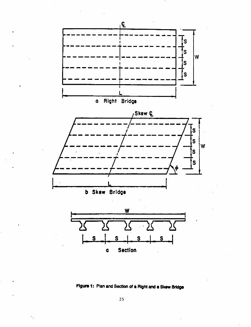
2.2.2 Effect of Skew
Since the Ridley Creek Bridge has a skew of approximately 45 degrees,
special attention was placed on the effect of skew on lateral load
distribution in the literature survey. It should be noted that the angle of
skew of a bridge superstructure is defined as the acute angle between the
support line of the superstructure and the longitudinal axis of the beams
(Figure 1). Therefore, a skew angle (¢) of 90 degrees indicates that the
structure is a right bridge (Figure la), and a large skew angle reflects a
5

bridge with a less severe skew. Although numerous studies had been
completed in lateral load distribution before the 1970's, very little work
before or since that time have focussed specifically on the effects of skew.
Two significant studies were conducted by VanHorn and Kostem at Lehigh
University and by Bakht and Moses of the Ontario Ministry of Transportation
and Communication and Case Western Reserve University respectively.·
The research at Lehigh University was primarily funded by PennDOT and
consisted of two separate research projects. The work extended from 1965 to
1980 and covered both spread box and I -beam bridges. Research included
field and experimental studies under service load conditions, as well as
computerized analysis which extended through the overload stage.
Initially, thirty skewed bridges of various widths, beam spacings, span
lengths, skew angles and number of beams were analyzed using the Finite
Element Method of analysis (5). Live load distribution factors were
computed for the interior and exterior beams for design vechicle loadings.
The computation of the load distribution factors is detailed in Reference 5.
This initial analytical investigation provided information into the behavior
of these bridges and helped determine the effect of each variable on lateral
load distribution.
A more comprehensive parametric study of 120 bridges with
configurations commonly encountered in practice was completed by DeCastro
and Kostem (6). With the results of this analysis, equations were developed
which evaluated the reduction in the load distribution factor for interior
and exterior beams on skewed bridges. The percent reduction is defined as
the amount of reduction required in the distribution factor when a right
bridge becomes skewed and therefore is always zero for right bridges. From
these studies, the parameters which significantly influenced the percent
6

reduction were found to be the bridge width, beam spacing, span length and
skew. Regression analyses resulted in the following equations for the
percent reduction for interior beams:
Where
Reduction factor to be applied to the distribution factor for an interior beam of a right bridge. Beam Spacing Curb-to-Curb Width Span Length Skew Angle
For exterior beams, a simplified equation was determined by trial and error:
Where
PCTREXT =50 (S/L - 0.12) cot~
Reduction (positive) or increment (negative) to be applied to the distribution factor for an exterior beam of a right bridge.
The above equations are limited to the following bridge dimensions:
4 1 -6" ~ s ~ 9 1 -0" 48 1 -0" ~ L ~ 120 I -0"
30° ~~ ~ 90°
Although the skewed bridge supers true ture is commonly found in
practice, very little research effort has gone into this area since the work
done by Lehigh University in the 1970 1 s. However, in a recent article,
Bakht and Moses have reviewed the practice of analyzing skewed bridges as
right bridges and also discussed the important factors affecting load
distribution in skewed bridges (7). The method of analysis used was the
Grillage Analogy Method. Although different methods of analysis were used,
Bakht 1 s results are similar to those of the Lehigh University researchers.
From the results of existing research, the following general
observations can be made regarding lateral load distribution in skewed
prestressed concrete !-beam bridges.
7

1. The distribution factor decreases with decreasing angle of skew.
2. The decrease in the distribution factor is gradual from 90 to 45 degrees but is abrupt from 45 to 30 degrees.
3. As span length increases, the amount of reduction in the distribution factor due to skew decreases.
4. For exterior beams, smaller reductions are obtained in shorter span bridges and increases in the distribution factor occur in longer bridge spans.
5. The bridge aspect ratio, beam spacing-to-span ratio, and skew angle significantly affect the amount of reduction.
2.3 Fatigue of Prestressed Concrete Beams
Fatigue characteristics of prestressed concrete beam members have been
the subject of research studies since the beginning of the engineering usage
of prestressed concrete (8), and the studies have continued until recent·
years (9, 10, 11, 12). Most research has focussed on the fatigue behavior
of the steel elements, leading to recommended limitations on stress ranges
in these elements. Some attention has also been given to the fatigue of
concrete, which is primarily in compression. Recommended stress range
limitations to insure against fatigue failure have been summarized in
reports by ACI Committee 215, Fatigue of Concrete Structures (13) and ACI
Committee 343, Reinforced Concrete Bridge Structures (14). The current
recommended limitations are as foliows:
1. Prestressed strands: 0.10 fpu where fpu is the ultimate strength of the strands
2. Non-prestressed deformed bars: 21 - 0.33 fmin + 8&, in ksi where fmin is the minimum tensile stress in ksi and a is the ratio of base radius to height of rolled-on transverse deformation which, may ordinarily be taken as 0.3
3. Concrete in compression: 0.4 f'c - 0.5 fern where f'c is 28 day compressive strength of concrete and fern is minimum compressive stress in concrete
The limitation for non-prestressed deformed bars has been incorporated
into the AASHTO Bridge Specifications (2) while the others have not.
8

It is easy to confirm that fatigue failure rarely occurs in "fully
prestressed" members, in which concrete fiber stress remains always in
compression and flexural cracks do not develop. In these members, the
stress range in prestressed strands due to live load is extremely low and
rarely exceeds a few kips per square inch. These values represent only a
small fraction of the fatigue limiting stress range. Thus, earlier research
work which dealt primarily with fully-prestressed members generally led to
the conclusion that fatigue was not a serious concern. Interestingly, the
same conclusion applies to ordinary non-prestressed reinforced concrete
members.
The situation was significantly changed with the gain of popularity of
partially prestressed concrete members. In this type of members,
prestressed strands and non-prestressed bars are combined to provide the
required bending moment strength. Tensile fiber stresses are permitted in
precompressed concrete. In extreme cases, the specified allowable tensile
stress exceeds the modulus of rupture of concrete and the member is actually
designed to be cracked under full service load. Naaman has demonstrated
that in partially prestressed members, the stress ranges in both prestressed
and unprestressed steel are considerably higher than those in comparable
fully prestressed or totally unprestressed members (15,16). Consequently,
partially prestressed members are more susceptible to fatigue distress than
fully prestressed members. Experimental studies at Lehigh University (17),
Portland Cement Association Laboratories (18) and University of Texas (12)
have demonstrated that the risk of fatigue failure is much more serious for
partially prestressed concrete members.
Another factor which could affect the fatigue strength of a structural
member is the complexity of its structural details. From studies of the
9

fatigue behavior of steel structural members, it has been well established
that fatigue is controlled by the local stress range which is strongly
influenced by the arrangement of the detail. S~eel structural details are
classified into categories A through F to reflect this influence (2, 19).
In a similar manner, the fatigue strength of prestressed concrete members is
affected by the structural details. For partially prestressed concrete
members, the structural details may include:
1. Rolled-on deformation of unprestressed reinforcing bars
2. Debonding of prestressing strands
3. Deflection of prestressing strands
4. Uneven contact between post-tensioned tendon and its conduit
5. Discontinuity and loss of bond at any transverse crack
A preliminary study at Lehigh University (20) has shown that a flexural
crack which does not break the bond would cause a very high stress
concentration, and hence a very severe fatigue condition. Very little
quantitative information is available regarding the effect of local
discontinuity on the fatigue strength of prestressed concrete members.
10

3. PRE-TEST ANALYSIS
3 .1 ~Introduction
Pre-Test analyses of the superstructure of Ridley Creek Bridge were
carried out in order to provide guidance to the instrumentation for the
field and laboratory testings. In the original planning, reconstruction
work was to start in August of 1988, only two months after the beginning of
the project. Only a small amount of analyses, on a very approximate basis,
was intended. The postponement of the reconstruction project to spring of
1989 afforded the researchers valuable time to expand this part of work. In
all, two aspects were studied: the prestress loss analysis of the pre-post
tensioned beams, and the effect of interior intermediate diaphragms.
3.2 Analysis of Pre-Post-Tensioned Composite Beams
One of the unique features of the Ridley Creek Bridge is the
combination of pre- and post-tensioning in the precast concrete beams. The
behavior of these beams is further complicated by the cast-in-place concrete
deck, with stay-in-place metal deck forms, which acts compositely with the
beams. Accurate analysis of structures of this type requires that special
attention be given to the time-differential between tensioning of
pretensioned strands, casting of the concrete beams, the transfer of pre
tensioning stress, the stressing of post-tensioned tendons and the casting
of the deck slab. In addition, the effect of differential shrinkage and the
presence of metal deck forms must be taken into consideration. The design
provisions contained in the AASHTO as well as PennDOT regulations did not
include all these considerations.
An earlier PennDOT research project (project 80-23), conducted by one
of the co-principal investigators of the present project had produced a
method for the detailed estimation of prestress losses in pre-post-tensioned
11

concrete beam members (21). As part of the pre-test analysis of the Ridley
Creek Bridge, the "Lehigh method" was used for a detailed loss analysis in
order to obtain a better estimation of the state of stresses in the bridge
beams.
The Lehigh method includes a computerized procedure and a more
simplified manual procedure. The manual procedure was used in the pre-test
analysis. The prestress loss analysis was performed for an interior beam in
span 1, as this was chosen to be the focus of field and laboratory testing
(see Section 4). As design and fabrication information gathered from
PennDOT was not complete, a number of assumptions had to be made, regarding
the fabrication schedule and material properties. This assumed information,
as well as information available from prestress beam shop drawings is listed
below:
Fabrication schedule: Time from the transfer of pretensioning stress (and the end of curing of beam)
Tensioning of pretensioning strands: -1 day (tensioning at one day before transfer)
Post-tensioning of tendons: 7 days
Casting of deck slab: 180 days
Concrete material properties: Since no fabrication data was available, the concrete strengths were assumed to be identical to those specified.
Beam concrete transfer strength: 4500 psi
Beam concrete compressive strength at post-tensioning: 4800 psi
28 day compressive strength: 5250 psi
Initial modular ratio: 7.3
Long term modular ratio: 7.0
Average loss characteristics: (SRL)
Post tension bars: 36.0 ksi
12

Prestressing strands: 45.5 ksi
Deck concrete 28 day compressive strength: 4000 psi Modular ratio (to beam concrete) 0.87
Pretensioned strands: Seven Wire 270 ksi stress-relieved strands
Post-tensioned tendons: 160 ksi Stressteel Bars
Jacking stress: 0.73 f's = 116.9 ksi
Friction coefficient: 0.15
Wobble coefficient: 0.0002/foot
Anchorage seating distance: 0 in.
Based on these values, the prestress loss of an interior beam in span 1
was calculated. Since the bridge was built in 1963, losses were calculated
for an age of 25 years (1988).
For pretensioned strands: For post-tensioned tendons:
The results were:
67.3 ksi, or 35.6% 42.3 ksi, or 36.2%
In contrast, the current AASHTO Specifications (2) provide prestress
loss values as follows:
For pretensioned strands: For post-tensioned tendons:
53.1 ksi, or 28.1% 37.8 ksi or 33.8%
It is seen that the more detailed Lehigh method predicted significantly
higher losses than the provisions of the AASHTO Specifications. These
losses are also greater than values used in the original design as well as
the recent rating computations (Section 2.1). An experimental determination
of the remaining prestress was included in Task 4 of this project. Without
such an experimental determination, it is not possible to evaluate the
different estimations.
As· pointed out earlier (Section 2 .1), the design of this bridge was
based on the 1957 AASHO (ASCE-ACI) provisions for prestress losses and
allowable stresses and a live load of the HS20-44 class. Using the
prestress losses predicted by the Lehigh method would increase the
13

calculated beam stresses. In particular, the computed lower fiber concrete
stress, under HS20-44 live load and impact, would be 658 psi in tension,
which would be approximately 3 times the allowable stress (3 ~) and 21%
over the predicted modulus of rupture (7.5 ~).
Since the "modulus of rupture" of concrete signifies the development of
flexural cracks in a concrete beam member, a tensile stress exceeding this
limit is theoretically impossible to occur. The calculated high stress
indicates only that the section is expected to be cracked. However, cursory
preliminary inspection by the researchers (and PennDOT routine inspections
in 1986 and 1988) has revealed no visible transverse cracks in the beam.
The contradicting evidence may be explained by one or more of the following:
1. The dead and live load stresses were computed based on AASHTO
specified distribution factors. These factors were conservatively
developed for the purpose of design, and were based on very much
simplified models of the superstructure. The actual structure is
much more complex, particularly in view of the severe skew and the
stay-in-place metal deck. The actual dead and live load stresses
are conceivably much lower than the calculated values.
2. The computation was based on the specified concrete strengths. In
reality, the strengths were probably higher.
3. The researchers have not been able to acquire any record of the
actual traffic on this bridge. Whether the live load (and impact)
has been as high as represented by the HS20-44 standard is open to
question.
14

3.3 Effect of Interior Diaphra~ms on Load Distribution in Skewed Prestressed Concrete I-Beam Brid~es
3.3.1 Back~round
Substantial effort was made in an investigation into the effects of
interior diaphragms on load distribution in skewed prestressed concrete I-
beam bridges. A Finite Element analysis parametric study was conducted on
south bound span 1 of the Ridley Creek Bridge which carries three lanes of
traffic on a 40 foot wide roadway that is at a skew of approximately 45
degrees. The superstructure consists of six PennDOT 20/39 pre-post-
tensioned concrete I-beams, topped with a 7-1/2" inch composite concrete
deck.
3.3.2 Objective
Two parameters were examined for their effects on the load distribution
characteristics of a severely skewed (45 degrees) I-beam superstructure.
1. Number and Location of Intermediate Interior Diaphragms
Four cases were studied: No intermediate diaphragms, one diaphragm at midspan, two diaphragms at third points and three diaphragms at quarter points.
2. Diaphragm Orientation
Two cases were studied: diaphragms placed perpendicular to the longitudinal axis of the beams and diaphragms placed parallel to the abutments.
As a basis for comparison, the same parameter variations were also used
in the analysis of a right (90° skew) bridge of the same span length.
Midspan deflections and the midspan moment distribution were used as the
principle indicators of the load distribution characteristics.
3.3.3 Finite Element Model
The cross section of the bridge superstructure, not including
diaphragms, was idealized into an assemblage of 12 isotropic plate elements
at mid-depth of the concrete deck and 6 eccentrically connected beam
15

elements located at the neutral axis of the composite prestressed concrete
!-beams. Each prestressed beam element was connected to the deck by a very
stiff vertical beam element, 25-3/4" in length, to simulate the full
composite action in the structure. The curb and divisor were modelled by
beam elements located along the outside edges of the overhanging deck.
Since the centroid of the curb and divisor are above the centroid of the
deck, the flexural inertia was modified by I = 10
+ Ad2 . Longitudinally,
the 64' span was divided into ten 4' -0" segments symmetrical about midspan
and two_ 6'-0" segments at each end. The idealized bridge cross section and
longitudinal divisions are presented in Figure 2.
Interior diaphragms, 2' -1" high by 0' -9" wide, were modelled by plane
stress elements. Each diaphragm consisted of two elements 25-3/4" deep
attached to the deck and prestressed concrete beam nodes. To account for
the extra depth, the thickness of the plane stress element was modified to
provide the same moment of inertia as in the actual diaphragm.
Diaphragms at the abutment and pier were modelled by beam elements
located along the deck nodes at the end of the structure. The flexural
inertia was modified to account for the eccentricity of the member's
centroid.
3.3.4 Loads
The design live load used for this study is the AASHTO HS20-44 vehicle.
Four load combinations were considered with load cases 1-2 and load cases 3-
4 intended to produce maximum effects in the exterior beam (Beam #6) and
interior beam (Beam #4), respectively . Figure 2 illustrates the lateral
. position of the vehicle on the structure for all four load cases.
Longitudinally, the load was placed with the drive wheels of the truck
directly over the midspan line for the right bridge. For the skewed
16

structure, the center-of-gravity of the drive axle was placed on the midspan
line. These locations will not produce the absolute maximum moment on the
structure. However, the deficiency was judged to be small and would not
justify the necessary increase in mesh complexity required to determine the
absolute maximum moment.
3.3.5 Analysis
The analysis results comparing midspan deflections and midspan moment
distribution are presented below.
Moment Distribution
Figures 3-10 illustrate the distribution of moment among the six
prestressed concrete !-beams at midspan for the three bridge configurations
and various load cases. The percentage of total bending moment carried by a
beam was calculated by dividing the moment in an individual beam by the
summation of moments in all six beams. The moment in any beam was defined
as the sum of two components:
1. Average of the bending moments in the two beam elements adjacent to midspan.
2. The moment of the force couple between the axial loads in the concrete deck and the prestressed concrete beam.
This procedure ignored the bending moment capacity of the concrete deck.
However, this was justified since calculations showed that the deck
contributed less than 1% of the moment at midspan.
In general, it appears that the moment is more uniformly distributed
among the beams when diaphragms are present. The addition of diaphragms
appears most benificial in distributing eccentric and localized load
conditions as in load cases 1 and 3. For bridges with a perpendicular
diaphragm configuration, Figures 3-6, the distribution characteristics
improve as the number of diaphragms increase. The maximum percentage of
17

total moment carried by an individual beam, or beam moment, in a structure
with 3 diaphragms is 12-19% below corresponding values in a structure
without diaphragms.
Figures 7 and 8 illustrate the distribution of moment in skewed bridges
with diaphragms placed parallel to the abutment for load cases 1 and 3.
With one diaphragm at midspan, the reductions in beam moment are 27% and 30%
for load cases 1 and 3 respectively. These values are significantly greater
than similar values for a structure with as many as three diaphragms placed
perpendicular to the beams. A similar result is present in Figures 9 and 10
for right bridges where a 35% reduction is possible with only one diaphragm
at midspan.
Earlier work by DeCastro and Kostem at Lehigh University (6) also
indicated that only one diaphragm at midspan is most benificial in
distributing load on right bridges. In fact, the 35% reduction in maximum
beam moment was the largest reduction recorded in this study. This
indicates that the skew angle is an important variable in defining the
effect of intermediate interior diaphragms on load distribution.
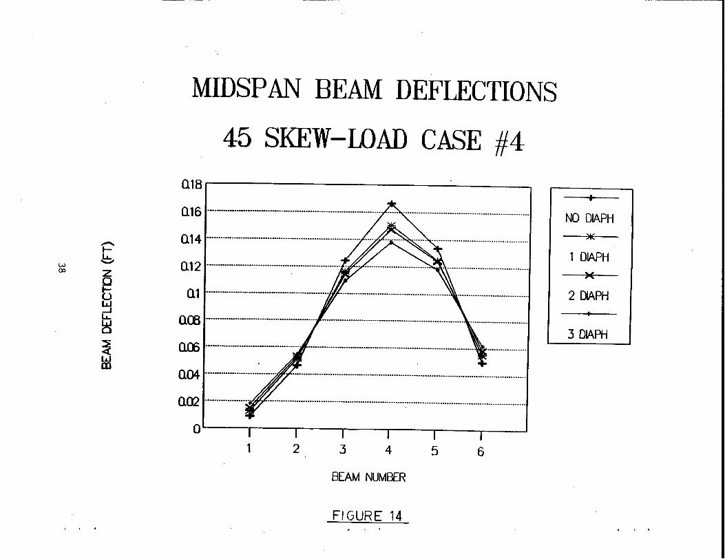
Midspan Deflections
Figures 11-14 and 15-16 illustrate the midspan deflection profile for a
skewed bridge with diaphragms placed perpendicular to the beam axis and a
right bridge respectively.
prestressed concrete beams.
The plot indicates deflections of the six
Reductions in midspan deflection due to the addition of interior
diaphragms perpendicular to the beams vary between 16-22% depending on the
load condition. For diaphragms placed parallel to the abutments, the
reduction is 1-4% less than those stated for perpendicular diaphragms. In
all three bridge configurations, the number of interior diaphragms had a
18

direct impact on the maximum beam deflection. In general, as the number of
interior diaphragms increase the midspan deflections will decrease.
It can also be seen that the addition of interior diaphragms has a
larger impact on deflections in non-skewed structures. However, the
deflections in a skewed bridge, regardless of diaphragm orientation, are 15-
25% lower than those of a right bridge with similar span length.
3.3.6 Preliminary Conclusions
General conclusions cannot be drawn from this study because of its
limited scope. No variation was made in the width of the bridge, length of
the span, angle of skew, number and spacing of the longitudinal beams, size
of the precast beams and thickness of the slab. Several, if not all, of
these foregoing parameters are likely to have an effect on the lateral load
distribution characteristics. Nevertheless, based on this limited study,
the following preliminary observations can be made.
1. Intermediate interior diaphragms decrease the midspan deflection in the beam directly below the live load.
2. The diaphragm orientation has virtually no effect on midspan deflections.
3. Intermediate interior diaphragms effectively create a more uniform distribution of the midspan bending moments among the longitudinal beams.
4. One diaphragm placed at mispan is most effective in distributing midspan moment in right bridges and skewed bridges with diaphragms placed parallel to the abutments.
5. Increasing the number of diaphragms in a skewed bridge with diaphragms placed perpendicular to the beams gradually improves the load distribution characteristics of the structure.
6. Intermediate interior diaphragms become more effective in distributing midspan moment as the angle of skew is increased.
19

4. FIELD TESTING AND BEAM REMOVAL
Only a small amount of work was accomplished on Task 2, field testing
and Task 3, beam removal. Because of the delay in reconstruction of the
Ridley Creek Bridge, the actual field testing and beam removal could not be
completed. The only work accomplished in this area was preliminary
planning.
Preliminary planning for the testing was initiated by making a visit
and cursory inspection of the bridge site with PennDOT District 6-0
personnel in August of 1988. From the ground, no cracks were visible in the
precast beams. However, indications of structural distress were noticed in
other areas of the bridge. These deficiencies were previously described in
the 1988 Bridge Inspection Report (Section 2.1).
Originally, the focus of study was concentrated on span 3 of the north
bound structure because of its low rating. However, after discussion with
PennDOT District 6-0 personnel and consideration of the reconstruction
sequence and access limitations at the site, this original plan was
abandoned. Instead, the study became focused on the first span of the south
bound structure.
The proposed initial stages of the reconstruction schedule were as
follows.
Stage 1: Widen the north bound bridge to 4 lanes.
Stage 2: Close traffic to the innermost south bound lane and the two inner north bound lanes to allow reconstruction of the north abutment (span 3).
Stage 3: Close traffic to the south bound structure to allow its reconstruction.
It was the intention of the researchers to develop a field testing plan
which was coordinated with this reconstruction schedule and would therefore
20

minimize interruption of the contractors activities. Preliminary plans were
developed as follows.
1. During the latter part of stage 1, before any modification to the southbound structure, a thorough field inspection will be made (Task 2a) and regular traffic strain measurements will be taken (Task 2b).
2. No field work will be conducted during stage 2.
3. At the beginning of stage 3, when public traffic will be diverted from the south-bound structure, test truck strain measurements will be taken (Task 2c).
4. Immediately after completion of Task 2c, the contractor will begin demolition of the south bound structure. At that time, the removal of prestressed beams (Task 3) for laboratory testing will be completed.
A draft set of detailed specifications for field testing and ,cutting
and removal of prestressed beams was developed and transmitted to PennDOT
District 6-0 in August 1988. The complete specification is included in
Appendix B.
21

5. CONCLUSIONS AND RECOMMENDATIONS FOR FUTURE STUDIES
Because of the unanticipated early termination of this project, the
various components of this study did not progress sufficiently to generate
substantive conclusions. Nevertheless, preliminary conclusions are derived
based on the literature review and the pre-test analyses. Also, areas for
potential future research are identified and suggestions are offered for
consideration if a project similar to this one is to be undertaken in the
future.
1. Fatigue is a serious possible failure mode for partially prestressed concrete members. Here "partial prestress" is defined to refer to designs which allow tensile stress in precompressed concrete under service condition, and/or which combines prestressed and unprestressed reinforcement. Extensive research is needed to quantify the fatigue characteristics of these members, particularly with reference to the transverse cracking of concrete and local debonding and change in prestress by blanketing and/or deflecting.
2. The skew of a bridge superstructure has a pronounced effect on the internal moment and shears if the skewness is severe. The current design procedure results in conservative structural design. However, additional research is needed to realistically estimate the internal moments and shears in each beam member for evaluation of fatigue, and to achieve improved economy in the design of severely skewed bridges.
3. The number and orientation of intermediate diaphragms affect the structural behavior of beam-s~ab type bridge superstructure having a 45° skew angle. More extensive analyses are necessary to fully understand this effect and to generate design guidelines.
4. The combination of pretensioned strands and post-tensioned tendons in the same structural member creates complexities in the analysis process with regard to estimation of prestress losses, behavior under service loads and the ultimate member strength. Reasonably accurate procedures are currently available for these analyses, but simplifications are needed for practical design usage.
5. The Ridley Creek Bridge is severely skewed and also contained prepost-tensioned beams with a smaller-than-usual depth to span ratio. The several unusual features of this bridge structure will obviously influence its behavior under service, as well as fatigue strength. The intended study would have provided an opportunity to explore the overlapping effects of these features on the behavior and strength of the bridge and the beams. With the termination of the project such an opportunity is lost. It is suggested that field and
22

laboratory studies be undertaken in the future, preferably on test structures each with an unusual characteristic so that its specific influence can be thoroughly investigated.
23

6. Figures
24
~-------- -- ~--_,_,_-----I
~----------t--- -------,__ ------.--1---------- w
~----~----~---------
~---------- ~---------
I . L o Ri9ht Bridge
.I Skewt
I --------1----------------t------- w
I
l -I b Skew Brid91
w
c:::g ~ ~ ·~ ~ I . s . I . s I . s I s I
c Section
Figure 1: Plan and Section of a Right and a Skew Bridge
25

w w w ! t 6' !2'f2't 6' LOAD CASE 4
I I I WIW I M LOAD CASE 3 I I I I
I I w I w 4' w I t
6' 6' wr t t t ( LOAD CASE 2 I I
I I I I
I I w 6' w2.1
t t 1 LOAD CASE 1 I I I I I I
X l )(
I )(
I )(
1 )(
I )(
I K
BM1 8M2 8M3 BM4 BMS BM6 2'-0" 2!.9 ..
5 G~8' = 4<Y
44'-9''
IDEALIZED BRIDGE CROSS SECTION AND LOAD CASES
64' l 2<46'•12' t 10••'•40' t 2•6'•12' l l I I I I I I I 1 I I I I. I I
BRIDGE ELEVATION WITH LONGITUDINAL DIVISIONS
FIGURE 2
26

N .......
1-z w ~ 0 ~ _J <( 1-0 1-
~
MIDSPAN MOMENT DISTRIBUTION
45 SKEW-LOAD CASE #1
~~----------------------~
4Q%t------
30% ·-------·----·--···-·····-···. ···-·-···-········-···········-···-······-···············
20%1---------·
10%
1 2 3 4 5 6
BEAM NUMBER
FIGURE 3
NO DIAPH )j(
1 DIAPH )(
2 DIAPH
3 DIAPH

N 00
1-z w ~ 0 ~ _J <( to t-·
~
MIDSPAN MOMENT DISTRIBUTION
45 SKEW~LOAD CASE #2
~~----------------------~
30%~---
2Q%t------
10%1-----
1 2 3 4 5 6
BEAM NUMBER
FIGUkF. 4
NO DIAPH
1 DlAPH )(
2 DlAPH
3 DlAPH

._ z
N w 1.0 ~
0 ~ __J <( ._ 0 ._ ~
MIDSPAN MOMENT DISTRIBUTION
45 S~EW-LOAD CASE #3
50%
NO DIAPH 40% )I(
1 DIAPH 30% - )(
2 DIAPH 20%
3 DIAPH 10%
0%
1 2 .· 3 4 5 6
BEAM NUMBER
1-"1 GURE 5

t--z w w 0 ~
0 ~ _J <( t--0 t--
~
MIDSPAN MOMENT . DISTRIBUTION
45 SKEW-IDAD CASE #4 35%
30% NO DIAPH )I(
25% 1 DIAPH
20% -·--·---)(
2 DIAPH
15% 3 DIAPH
10%
1 2 3 4 5 6
BEAM NUMBER
FIGUhL. (

MIDSPAN MOMENT DISTRIBUTION
45 SKEW-LOAD CASE #1 (SKEW DIAPH) ~%~--------------------~
40%1-------·--
30% ---·--
2Q%t-------
10%1-----
1 2 3 4 5 6
BEAM NUMBER
FIGURE 7
NO DIAPH )f(
1 DIAPH )(
2 DIAPH
3 DIAPH

1--w z N w ~ 0 ~ ..:.J <( 1--0 1--
~
MIDSPAN MOMENT DISTRIBUTION
45 SKEW-LOAD CASE #3 (SKEW DIAPH)
50%
NO DIAPH 40% )I(
1 DIAPH 30% )(
2 DIAPH 20%
3 DIAPH 10%
1 2 3 4 5 6
BEAM NUMBER
FIGURE 'j . . .

' ' .
I-w z w w
~ 0 ~ _J
~ I-0 I-
~
. ' .
MIDSPAN MOMENT DISTRIBUTION
NO SKEW - WAD CASE #1
50%
NO DIAPH 40% )I(
1 DIAPH 30% X
2 DIAPH 20%
3 DIAPH
10% ··-------··--··-----------·-··
0%
1 2 3 4 5 6
BEAM NUMBER
FIGURE 9

t-w z ..,.. w
~·
0 ~ _J
4: to I-·
~
MIDSPAN MOMENT DISTRIBUTION
NO SKEW - LOAD CASE #3
~~----------------------~
40%1-----------
30% ··------'----!-
20% 1------"----
10%1----
1 2 3 4 5 6
BEAM NUMBER
FIGUhE 10 . ' '
NO DIAPH
1 DIAPH )(
2 DIAPH
3 DIAPH

' ' .
.......... ..,_ b z Q
tl ~ u_. w 0
~ w Q).
0 I 0
MIDSPAN BEAM DEFLECTIONS
45 SKEW-LOAD CASE #1
Q12r--------------,
QOO ····························································:······································. ········································
Q()) ·························································································· ···················································
Q04 ················································································· ····························································
Q()2 ································································· ·······················:··················································
. 1 2 3 4 5 6
BEAM NUMBER
FIGURE 11
o I o
NO DIAPH )j(
1 DIAPH )(
2 DIAPH
3 DIAPH

-1-w b CJ\
7
Q tl w _J LL
~ ~ <{ w m
MIDSPAN BEAM DEFLECTIONS
45 SKEW-LOAD CASE #2
02~------------------------~
Ql ········································································ ····································································
Qffi ···························-························· ...................................................................................... .
0 ·················· ··························································································································
1 2 .3 4 5 6
. BEAM NUMBER
FIGURE 12 . ' .
NO DIAPH
1 DIAPH )(
2 DIAPH
3 DIAPH

' ' . • ,, f
MIDSPAN BEAM DEFLECTIONS
45 SKEW-LOAD CASE #3 Q12 r-----------------,
Q 1 ················································································· ····························································
Q04 ··················································· ····························································· ····························
1 2 3 4 5 6
BEAM NUMBER
Fl GURE 13
. ( '
NO DIAPH
1 DIAPH )(
2 DIAPH
3.DIAPH
w 00
MIDSPAN BEAM DEFLECTIONS
45 SKEW-LOAD CASE #4
Q18r----------------..
Q 16 ····-····-··-········-····················································· ..... . . ··········· ................... ······· ................. .
Q 14 ····································································· .... . .. ····· ······ ·····························--------------
Q 12 ···························································- ·- .. ······························ ---···························--------
Q 1 ....................................................... ·················································· ································
QCB ·······································:········· ································································ ··············-···········
Q(6 .......................................... ··········································································· ·······-·········-
Q04 ····-·························· ··········································································································
Q02 ····················
a~~~~~~~~-~-~-~
1 2 3 4 5 6
BEAM NUMBER
FIGURE 14 . '~ '
NO DIAPH )I(
1 DIAPH )(
2 DIAPH
3 DIAPH

' . .
-t-b z Q
t5 w _J LL w 0
~ <i w Ol
J 1, • ' I '
MIDSPAN BEAM DEFLECTIONS
NO SKEW LOAD CASE #1 014...----------------.
1 DIAPH
QCS ...................................................... :................................. ···················································· )(
2 DIAPH QC6 ·············································································· ·····························································
Q04 ································································· ... ········································································· 3 DIAPH
1 2 3 4 5 6
BEAM NUMBER
FIGURE 15

, . .
-t-b z 0 ti w ....J u.... ~
~ w m
MIDSPAN BEAM DEFLECTIONS
NO SKEW-LOAD CASE #3 Q14r-----------------,
QC6 ·-············································- - ······-··-················-·········-······-------··········· ------···········----··------
Q()2 . .................. .. ··············-··················--················-··········-····--··---·-·--··-·-·-·-------------------------------
1 2 3 4 5 6
BEAM NUMBER
FIGURE 16 1 '( '
NO DIAPH )f(
1 DIAPH )(
2 DIAPH
3 DIAPH

References
1. American Association of State Highway Officials Standard Specifications for Highway Bridges, Seventh Edition, 1957
2. American Association of State Highway and Transportation Officials Standard Specifications for Highway Bridges, Thirteenth Edition, 1983
3. U.S. Department of Commerce - Bureau of Public Roads, Criteria for Prestressed Concrete Bridges, 1955
4. Zellin, M.A., Kostem, C. N., VanHorn, D. A., Kulicki, J. M. Load Distribution Factors for Prestressed Concrete I-Beam Bridges Fritz Engineering Laboratory Report 387.2b, Lehigh University, January 1976
5. DeCastro, E. S., Mertz, D. R., Kostem, C. N., VanHorn, D. A. Live Load Distribution in Skewed Prestressed Concrete I-Beam and Spread Box Beam Bridges, Fritz Engineering Laboratory Report 387.3, Lehigh University, August 1979
6. DeCastro, E. S., Kostem, C. N. Lateral Load Distribution in Skewed Prestressed Concrete I-Beam Bridges Fritz Engineering Laboratory Report 400.16, Lehigh University, July 1975
7. Bakht, B., Moses, F. Lateral Distribution Factors for Highway Bridges ASCE-Journal of Structural Engineering Vol. 114 (No. 8), August 1988
8. Ekberg, C. E. Jr. The Characteristics of Prestressed Concrete Under Repetitive Loading Journal of the Prestressed Concrete Institute, Vol. 1, No. 3, Dec. 1956
9. Hanson, J. M., Hulsbos, C. L. and VanHorn, D. A. Fatigue Tests of Prestressed Concrete !-Beams Journal of the Structural Division, Proceedings of ASCE, Vol. 96, STll, Nov. 1970
10. Naaman, A. E. Fatigue in Partially Prestressed Concrete Beams Fatigue of Concrete Structures, ACI Publication SP-75, 1982
11. Paulson, K. Jr., Frank, K. H., and Breen, J. E. A Fatigue Study of Prestressing Strand, Research Report 300-1, Center for Highway Research, University of Texas at Austin, April 1983
12. Overman, T. R., Breen, J. E., and Frank, K. H. Fatigue Behavior of Pretensioned Concrete Girders, Research Report 300-2F, Center for Highway Research, University of Texas at Austin, Nov. 1984
41

13. ACI Committee 215 Consideration for Design of Concrete Structures Subjected to Fatigue Loading, Journal of the American Concrete Institute, Vol. 71, No. 3, March 1974
14. ACI Committee 343 Analysis and Design of Reinforced Concrete Bridge Structures American Concrete Institute Publication 343R-88, 1988
15. Naaman, A. E. and Siriaksom, A. Serviceability Based Design of Partially Prestressed Beams, Journal of the Prestressed Concrete Institute, Vol. 24, Nos. 2 and 3, March/April and May/June 1979
16. Harajli, M. H. and Naaman, A. E. Static and Fatigue Tests on Partially Prestressed Beams Journal of the Structural Division, Proceedings of ASCE, Vol. 111, No. ST7, July 1985
17. Fisher, J. W., Huang, T., Slutter, R. G., and Au-Young, C. Static and Dynamic Test of Beams from the Conneaut Swamp Bridge, Fritz Engineering Laboratory Report 423.1, Lehigh University, July 1980
18. Rabbat, B. G., Karr, P. H., Russell, H. G., and Bruce, R. N. Jr., Fatigue Tests of Pretensioned Girders with Blanketed and Draped Strands, Journal of the Prestressed Concrete Institute, Vol. 24, No. 4, July/August 1979
19. Keating, P. B., and Fisher, J. W. Evaluation of Fatigue Tests and Design Criteria on Welded Details NCHRP Report 286, Sept. 1986
20. Vargas, R. A., Yen, B. T. and Huang, T. Steel Stresses in Cracked Prestressed Concrete Beams, Technical Report, Fritz Engineering Laboratory, Lehigh University, May 1980
21. Huang, Ti Users Guide for Prestress Loss Estimation Procedures Fritz Engineering Laboratory Report 470.2, Lehigh University, December 1982
42

Appendix A: Project Tasks and Time Schedule
43

PennDot Research Project 87-04 Fatigue Testing of Prestressed Beams
r--
Progress Bar Chart
1988
J J AS 0 N 0 J F M A M J - ,_ Phase I
I I I I
Task I Literature Search
Task 2 Field Studies
a) Inspection of Bridge --b) Live Load Stresses
c) Teat Truck Loading
d) Evaluation
Task J Removal of Beams
Task 5(a) Interim Report 1 B R
PhaRe I I
Task 4 Laboratory Studies a) Fatigue Testing b) Static Testing ~
c) Material Properties
d) Evaluation
Task 5(b) Final Report
..
R Briefing Meetings in Harrisburg
Planned Actual
Quarter Ending
1989 1990
J A s 0 N 0 J F IM A M J J A s 0 N 1-f.-- -
--H~
I ! 1 _I _l I
- . ~ --
B - 1- -~

Appendix B: Draft Specification for Field Testing and Cutting and Removal of Prestressed Concrete Beams
45

•
SPECIFICATIONS FOR FIELD TESTING AND CUTTING AND REMOVAL OF PRESTRESSED CONCRETE BEAMS
Lehigh University, under Pennsylvania Department Of Transportation Research Project No. 87-04, will be conducting load testing of the prestressed concrete beams in the south-bound Ridley Creek Bridge (L. R. 1018, Sta. 505+68. 46) during the reconstruction of this bridge. The reconstruction contractor shall cooperate with Lehigh research personnel and perform tasks requested by Lehigh research personnel as described in the following. The cost of such cooperation and tasks shall be included in the reconstruction agreement, payable by PennDOT, and not to be charged to Lehigh University.
For the purpose of contact, the Lehigh research personnel include Dr. BenT. Yen (Tel. 215-758-3536), Dr. Ti Huang (215-758-3528), Mr. Mark Kaczinski (215-758-3544), or their designated representatives.
TASK NO. 1: FIELD TESTING - TRAFFIC LOAD
1. Near the end of Reconstruction Phase 1, when all three southbound lanes remain open to normal traffic, Lehigh will conduct a field inspection, install strain gages on prestressed concrete beams and monitor strains under the normal traffic condition .
2. The contractor shall notify Lehigh University personnel at least two months before the estimated completion date of Phase 1.
3. The work by Lehigh research personnel will take approximately eight working days. During this time, complete access to the area beneath the south-bound structure in spans 1 and 2 will be required. The contractor shall cooperate with the Lehigh team and not interfere with its work.
4. The contractor shall provide maintenance and protection of traffic along Sun Drive in accordance with Publication ?. In particular, the contractor shall provide these measures for the Lehigh University instrument van which will be parked on Sun . Drive beneath span 1 of the south-bound bridge and adjacent to the pier bent.
5. At the completion of Task 1, all strain gages and connecting wires will remain attached to the beams with suitable protection. The contractor shall exercise caution in subsequent work (through Reconstruction Phase 3) to avoid damage.
TASK NO. 2: FIELD TESTING - TEST TRUCK LOAD
1. At the beginning of Reconstruction Phase 3, after public traffic has been diverted from all three lanes of._ the_ ,south-
46
------

bound structure, and before any modification of the southbound structure, the Lehigh researchers will conduct testing of the structure using special "test trucks". Obtaining and scheduling the "test trucks" will be the responsibility of Lehigh University.
2. The contractor shall notify Lehigh University personnel no later than one week before the installation of maintenance and protection of traffic requirements for Reconstruction Phase 3, and the diversion of south-bound traffic onto the north-bound structure.
3. The work shall take approximately two working days. Throughout this period, the contractor shall ensure that the entire south-bound bridge, as well as approximately 1 mile of roadway on each end of the structure is clear of all construction personnel, materials and equipment.
4. The contractor shall provide maintenance and protection of traffic along Sun Drive in accordance with Publication?. In particular, the contractor shall provide these measures for the Lehigh University instrument van which will be parked on Sun Drive beneath span 1 of the south-bound bridge and adjacent to the pier bent.
5. The contractor shall not begin the demolition of any part of the south-bound structure until the Lehigh researchers have completed this task.
TASK N0.3: BEAM REMOVAL AND CONCRETE CORES
The contractor shall cut and remove three prestressed concrete beams and obtain 24 concrete core specimens as designated by the Lehigh University researchers after the latter have completed the test truck loading study in Task 2.
A. Cutting and Removal of Prestressed Concrete Beams
1. Three interior beams (Nos. 2,3 and 4), approximately 64 feet long, in span 1 of the south-bound structure (as shown on the attached sketch) shall be isolated and removed for shipping to Lehigh University for study.
2. The beams shall be isolated by making four longitudinal cuts in the direction of the bridge as shown in the attached plan. The ·cuts shall be midway between the beams and shall be done in a maner that will result in smooth edge surfaces for the separated T-beams. Sawcutting or an approved equal shall be used. Equipment like a jackhammer shall not be used, as it will damage the concrete and steel adjacent to the cutting.
3. The cutting shall include cuts through both the intemediate and end diaphragms as shown on the attached sketch. The result of cutting shall be three symmetrical T-beams with
47
'
•

•
approximately 8 foot wide deck slabs and segments of intermediate and end diaphrams. Each of the T-beam specimens will weigh approximately 45 tons.
4. At the conclusion of the testing described in Task 2, a number of strain gages will remain attached to the prestressed concrete beams with appropriate protection applied by Lehigh University personnel. Care shall be exercised in cutting the three designated beams so as not to damage the attached strain gages and connecting wires.
5. While making logi tudinal cuts, the contractor shall take caution to laterally brace the isolated beams, in order to prevent tilting. This _is particularly important for the fascia beam (No. 1) which is unsymmetrical. (This beam is not needed by Lehigh University for testing. However, its removal from the substructure must be carefully done so as to enable the coring described in Task 3B.)
6. After cutting, the contractor shall lift the three isolated interior T-beams off the substructure and place them on trucks arranged by Lehigh University for transportation. The contractor shall be responsible for the T-beams until they are safely placed on the transporting trucks, after which the responsibility passes to Lehigh University. The contractor shall provide advance notification (at least two weeks) to Lehigh, so that the transportation trucks can be arranged and present at appropriate times.
7. Lifting of the isolated T-beams shall be done by the contractor with great care to avoid damage. Lifting points shall be placed as close as possible to the ends of the beams. Intermediate lifting points shall not be permitted. Lifting shall be done by using cradle-type devic~s at the bottom of the beams, and tension members passing through small hole drilled through the deck ·slab. Lifting directly by the deck slab shall not be permitted. Before lifting, adequate bracing of ·the overhanging deck slab shall be provided at a 8 · -0" spacing. (See attached photograph)
B. CONCRETE CORES
1. The contractor shall take twelve 6" diameter cores from the web of the removed fascia beam (No. 1) and twelve 6" diameter cores from the deck slab between beams 5 and 6.
2. The 24 core locations shall be designated by Lehigh University personnel at least one week prior to coring.
3. The coring procedure shall conform to ASTM specification C42-84a.
48

<l SUN .DRIVE (BELOW)
BEAMI /
- -B~Ml + - - - ---BE~M3 +------
LONGI~~kNAL) CUTS _ _ _ _ t _ _ _ _ · BEAM 4
- - BE: AM s t -- - -- SOUTH -BOUND STRUCTURE
BEAM b I / ----~=::=::=::=::=::=:::::::=::=::=::=:::;L ____ Cf. LR. 101 B
~ PIER DIA.PH.~ , CTYP.) #'
/ ~INTER. DIAPH. A L (TYP.) /Y
~_/_--.--.....___/ ~ABUT. DIAPH. /
, lTYP. /-----~~-~
r---./ _____ 1 __ /
/ (l.. PIER ''1"
SPAN \
NORTH- BOIJND STRUCTURE
PARTI~L FRAMING PLA~- SP~N 1 N.T. s.
' ....