commonwealth of massachusetts · pdf filecommonwealth of massachusetts department of...
TRANSCRIPT

COMMONWEALTH OF MASSACHUSETTS
DEPARTMENT OF ENVIRONMENTAL PROTECTION
STANDARD REFERENCES FOR MONITORING WELLS
SECTION 4.1 MONITORING WELL NETWORK DESIGN
Section 4.1
Page i January 1991
SECTION 4.1
MONITORING WELL NETWORK DESIGN
TABLE OF CONTENTS Section Title Page No. 4.1-1 PURPOSE ............................................................................................... 1 4.1-2 DESIGN CONSIDERATIONS .................................................................. 2 4.1-2.1 Objective(s) of the Investigation .............................................................. 2 4.1-2.1.1 Investigations at Uncontaminated Sites.................................................... 2 4.1-2.1.2 Investigations at Contaminated Sites ....................................................... 2 4.1-2.2 Collecting Representative Data ................................................................ 2 4.1-2.3 Maximizing the Information with a Limited Number of Wells ................... 3 4.1-2.4 Incorporating Flexibility in the Design ...................................................... 3 4.1-2.5 Budget Considerations ............................................................................ 4 4.1-3 DEFINING THE PROBLEM...................................................................... 4 4.1-3.1 Understanding the Physical Setting.......................................................... 4 4.1-3.1.1 Geology ................................................................................................... 4 4.1-3.1.2 Hydrogeology ........................................................................................... 5 4.1-3.1.3 Existing Surface and Subsurface Structures ............................................ 5 4.1-3.1.4 Conceptual Model. ................................................................................... 5 4.1-3.2 Understanding the Physical and Chemical Characteristics of Contaminants .............................................................. 5 4.1-3.2.1 Aqueous Dissolved Phase Liquids (ADPLs).............................................. 6 4.1-3.2.2 Non-aqueous Phase Liquids (NAPLs) ..................................................... 6 (a) “Floaters" .......................................................................................... 6 (b) "Sinkers".............................................................................................. 6 4.1-3.3 Preliminary Exposure Characterization ................................................... 7 4.1-4 METHODOLOGY . .................................................................................. 7 4.1-4.1 Compilation of Available Background Data .............................................. 7 4.1-4.2 Well Locations .......................................................................................... 8

Section 4.1 Page ii
January 1991
SECTION 4.1 MONITORING WELL NETWORK DESIGN
TABLE OF CONTENTS
(continued) Section Title Page No. 4.1-4.2.1 Horizontal Spacing................................................................................... 8 (a) Upgradient Wells .............................................................................. 9 (b) Downgradient Wells ......................................................................... 9 4.1-4.2.2 Vertical Spacing...................................................................................... 10 4.1-4.3 Selection of Well Type............................................................................ 10 4.1-4.3.1 Piezometers ........................................................................................... 11 4.1-4.3.2 Observation Wells .................................................................................. 11 4.1-4.3.3 Monitoring Wells ..................................................................................... 12 (a) Single Standpipe Wells .................................................................. 12 (1) Depth-specific Wells ............................................................ 12 (2) Depth-integrated Wells ........................................................ 12 (b) Multi-level Wells .............................................................................. 13
(1) Stacked Wells (Well Nest) .................................................. 13 (2) Well Cluster ......................................................................... 14 (3) Specialized Well Systems: Waterloo, Westbay,
and Barcad................................................................................... 14 REFERENCES ............................................................................................................. 16 ADDITIONAL REFERENCES ....................................................................................... 16

Section 4.1
Page iii January 1991
LIST OF FIGURES
Figure Title Page No. 4.1-1 Geologic Cross-section.......................................................................... .18 4.1-2 Ground Water Contour Map .................................................................... 18 4.1-3 Sketch of Floating Contaminant............................................................. .19 4.1-4 Illustration of Sinking Contaminant in a Porous Material.................................................................................... 20 4.1-5 Illustration of Sinking Contaminant in Fractured Bedrock .................................................................................. 21 4.1-6 Basic Well Types ..................................................................................... 22 4.1-7 Waterloo Multilevel Monitoring Well Detail ............................................ .23 4.1-8 Westbay Multilevel Well .......................................................................... 24 4.1-9 Typical Barcad Installation .................................................................... .25 4.1-10 Detail of a Barcad Sampler.................................................................... .26

Section 4.1 Page 1
January 1991
SECTION 4.1 MONITORING WELL NETWORK DESIGN 4.1-1 PURPOSE The following section presents guidelines for the design of monitoring well networks. Monitoring wells are installed for a variety of reasons including:
o To determine horizontal and vertical hydraulic gradients that influence the direction of ground water flow.
o To obtain measurements of aquifer properties, primarily hydraulic conductivity,
utilizing in-situ hydraulic conductivity tests and pump tests.
o To monitor changes in water quality over time.
o To define the two- or three-dimensional distribution of contamination in an aquifer.
o To evaluate the effectiveness of remedial measures.
Frequently, not enough attention is given in field investigation programs to the design of well networks. If the network is not properly designed, important features relating to both the hydrogeology and chemical composition of the water within an aquifer may not be gathered. If this occurs, one might reach erroneous conclusions about conditions at the site. This could result in inadequate definition of potential receptors and improper design of remedial measures. The design of a monitoring well network is site-specific. It is important to understand that the conditions at each site are unique and, therefore, site-specific factors affecting ground water flow and contaminant migration must be considered when designing an appropriate monitoring well network. It also makes a difference whether the network is being designed to define a plume of contamination migrating from a known source or to identify a source from a downgradient point or area of contamination. Design of a network requires input from experienced individuals familiar with the interrelationships of geology, hydrology, and ground water chemistry, as well as the suitability of various drilling and well installation methods. This section will focus on designing well networks for contaminant plume investigations and not networks specifically used to gather pump test data. Guidance on the design of pump test monitoring systems is available from the DEP, Bureau of Resource Protection, Division of Water Supply. However, it should be noted that the two are not mutually exclusive. Certain sites may involve conducting a pump test at some phase of the contaminant investigation.

Section 4.1 Page 2
January 1991
4.1-2 DESIGN CONSIDERATIONS The following factors should be considered in the development of a network design:
o The objective(s) of the investigation.
o Data collected from the wells must be representative of the aquifer conditions.
o A desire to maximize the information obtained from a limited number of wells.
o Flexibility - modification of the placement and design of monitoring wells must be possible, based on new information acquired in the field.
o Budget
4.1-2.1 Objective(s) of the Investigation The objective(s) of the investigation must be clearly defined in order to design an effective monitoring well network. Generally, investigations can be divided into two categories: uncontaminated sites where hydrogeologic monitoring is required or hydraulic characteristics are to be evaluated and contaminated sites where both aquifer hydraulic characteristics and ground water chemistry must be evaluated. 4.1-2.1.1 Investigations at Uncontaminated Sites Monitoring wells may be installed at uncontaminated sites to observe draw-down during a pump test, to perform slug tests in order to estimate hydraulic conductivity, to obtain water-level data to determine ground water gradients and flow directions, and to monitor the impact of various activities on the hydraulic head. In many cases ground water sampling is not required in these investigations. If ground water chemistry and contaminant characteristics are not a concern, then the network design may need to consider only the site geology and hydrology. 4.1-2.1.2 Investigations at Contaminated Sites In many types of contamination investigations the best approach is to perform field studies in phases, incorporating an increasing level of complexity with each phase as more information concerning specific site conditions is collected and analyzed. The network becomes denser or more extensive with each successive phase. The network design will be influenced by the migration pattern of the contamination problem being investigated as well as by the chemistry of the contaminants. From a point of contamination where the source is unknown, the network design extends in the upgradient direction seeking to locate the source. From a known source of contamination, the network is designed to characterize the three-dimensional extent of the plume in the downgradient direction.

Section 4.1 Page 3
January 1991
4.1-2.2 Collecting Representative Data In designing a network for a site investigation, consideration must be given to the influence of the drilling techniques, well construction materials, well location, and installation depth to ensure that the environmental samples and analytical data generated from the wells are representative of the site. There are numerous cases where the conditions at a site have been improperly characterized due to introduction of chemicals during drilling and installation of monitoring wells. 4.1-2.3 Maximizing the Information with a Limited Number of Wells With the exception of research sites, there are rarely enough data to thoroughly characterize a site. The primary reasons for this are that the understanding of subsurface processes is incomplete and the costs associated with subsurface studies and well installation programs are very high. Consequently, it is desirable to maximize the amount of information that can be collected from each borehole and well. If both water level and water quality data are being collected, then the well design should allow proper placement of wells so that contaminants are intercepted and adequate sizing so that sampling equipment can be lowered into the well. As the depth of the borehole increases, multi-level well installations become increasingly cost-effective. In order to maximize the information obtained from a limited number of wells, it is important to monitor drilling progress continuously, to collect soil samples frequently, to evaluate the characteristics of the subsurface materials encountered, and to monitor the samples for contaminants. During the drilling process, if appropriate, estimation of the aquifer in-situ borehole permeability and visual classification of soil samples should be employed to evaluate variations in permeability and to determine the most suitable zone for installing the well screen. 4.1-2.4 Incorporating Flexibility in the Design It is important that the initial design provides for modifications based on an evaluation of new data acquired during the field program. The final design must be based on an understanding of the subsurface geology and other site characteristics. Typically, collection of new subsurface information occurs concurrently with well installation programs. If existing site information is limited or if the field investigation reveals important differences from the original assumptions, the network design should be re-evaluated based on this new data. For example, the detection of separate phase liquids or identification of a highly permeable zone may require specific types of well installations or materials. If these considerations are not taken into account, the collection of appropriate information that is most relevant to the investigation may not be obtained. This might result in the omission of significant information about the site.

Section 4.1 Page 4
January 1991
Final decisions on boring locations and well placement should be based on evaluation of the data acquired during the field program. Field personnel should have adequate experience and authority to make changes in the initial design when such changes are related to new information about field conditions. One should not hesitate to stop drilling to examine new data if it affects drilling locations. The cost of drilling one poorly located well far outweighs the cost of remobilizing the drilling rig in almost every case. 4.1-2.5 Budget Considerations The amount of money available for subsurface investigations and well installations directly influences the network design. In order to get the most information for the available funds, data gaps existing at a site must be identified and prioritized before initiating a site investigation. Attempts should be made to fill the data gaps to the extent practicable. For example, if the site geology or hydrogeology is thought to be complex and the existing data is limited, it would be inappropriate to install only two wells containing a large number of expensive multi-level sampling instruments. For the same amount of money, several monitoring wells/piezometers might be installed across the site to provide more insight into the basic geologic and hydrogeologic conditions. Too often, a disproportionate amount of funds are spent on chemical analytical work, leaving inadequate funds for an accurate characterization of the site hydrogeology. Even the most sophisticated analysis is useless if the wells have not been properly designed and located. 4.1-3 DEFINING THE PROBLEM The scope of the network design is dependent on many factors including the extent of available information, the complexity of the site geology and hydrogeology, the proximity of downgradient receptors, the nature of the contaminants, if any, and access to and around the site. Proper network design requires a basic knowledge of the following factors:
o Physical setting. o Character of the contaminants. o Preliminary determination of exposure pathways.
Important aspects of each factor are discussed on the next page: 4.1-3.1 Understanding the Physical Setting Characterizing the physical setting is often the first step taken prior choosing well locations and well types. Often this factor, more than any other, controls the final design of a well network.

Section 4.1 Page 5
January 1991
4.1-3.1.1 Geology In order to design an effective monitoring well network, the nature and variability of the site geology must be understood. Small-scale heterogeneities can have a significant impact on the movement of contaminants. Borings and monitoring wells should be posi-tioned, if possible, so that geologic cross-sections can be constructed across a site at various locations and orientations (see Figure 4.1-1). Knowledge about the regional geologic history of a site is essential for accurate subsurface interpretations. In the more detailed phases of an investigation, information on grain-size, porosity, and permeability may be useful in refining a network design. Geophysical investigations also may be helpful in defining subsurface conditions. 4.1-3.1.2 Hydrogeology An evaluation of the hydrogeology of the site is another fundamental aspect of network design. This information may range from an estimate of ground water flow directions based on a review of topographic map features to a detailed assessment of variations in horizontal and vertical gradients at the site and the interaction of the ground water with surface water features. The influence of nearby pumping wells and ground water sinks created by subsurface utilities also should be considered. An assessment of the hydrogeologic conditions at a site typically involves the construction of ground water contour maps, flow nets and permeability calculations (see Figure 4.1-2). 4.1-3.1.3 Existing Surface and Subsurface Structures An assessment of significant surface and subsurface features is necessary for an effective network design. Dig-Safe should be contacted to determine the location of underground utilities in public right-of-way before initiating any subsurface investigations. Dig-safe requires at least three days notice and may or may not trace lines across private property. If applicable, local sewer and water departments should be contacted to locate municipal utilities. A site map showing private utilities should be obtained whenever possible. Man-made features such as overhead utilities and trees and buried utilities such as storm drains, septic tanks, and leaching fields, as well as property boundaries and roadways may significantly affect access to drilling sites and, hence, the placement of wells. Additionally, subsurface trenches and active pumping wells can significantly alter natural ground water flow directions and contaminant distribution. 4.1-3.1.4 Conceptual Model Well networks should be based on a conceptual geologic and hydrogeologic model of the site conditions. In most investigations it is prudent to incorporate monitoring points that serve to prove or disprove the validity of this conceptual model. This may include wells placed in low permeability areas to provide quantification and validation of the actual permeability and to determine if contaminants, though not expected, are actually present.

Section 4.1 Page 6
January 1991
It may also include placing wells at suspected recharge/discharge boundaries to establish ground water flow conditions. A complete conceptual model should incorporate both vertical and horizontal flow conditions (i.e. flow net). The importance of developing a conceptual model cannot be overemphasized. 4.1-3.2 Understanding the Physical and Chemical Characteristics of Contaminants Characteristics of the natural ground water quality and any contaminants in the aquifer will affect the fate and transport of chemical species in the aquifer. Contaminants can be sub-divided into two main categories: aqueous dissolved phase liquids (ADPLs) and non-aqueous phase liquids (NAPLs); the latter group includes both "floaters" and "sinkers." Once an assessment has been made of the potential sources, the types of contaminants, and the suspected contaminant concentrations, information on the characteristics of each contaminant should be compiled. Important chemical characteristics that should be evaluated include solubility, specific gravity, viscosity, octanol/water partition coefficient, Henry's Law Constant, and degradation by-products. These characteristics influence the spatial distribution of the contaminant in the aquifer, how it reacts with water, and how it will migrate and degrade in the aquifer. These chemical characteristics must be taken into account when developing a monitoring well network, as they will influence the correct placement of the monitoring wells. 4.1-3.2.1 Aqueous Dissolved Phase Liquids (ADPLs) Dissolved phase solutes, both inorganic and organic, move with the ground water, though their rate of travel may be different due to sorption, desorption, and degradation during transport. Dissolved phase solutes include miscible compounds such as methanol, ethanol, acetone and salts; partially miscible compounds such as Methyl Ethyl Ketone (MEK); and somewhat soluble compounds such as benzene. The solubility of metals varies widely and are greatly affected by the ground water chemistry. Essentially, all inorganic and organic compounds are soluble to some degree and may be found in the dissolved phase. The presence of the contaminant in the dissolved phase will not significantly affect the density of the water unless the concentration is in the range of 104 or 105 ppm. 4.1-3.2.2 Non-Aqueous Phase Liquids (NAPLs). (a) "Floaters" Those contaminants with a specific gravity of less than 1 will float on top of the
water table aquifer as a separate, non-aqueous phase. Gasoline and the components of gasoline: benzene, toluene, and xylene (BTX) are usually considered "floaters." Gasoline spills often move erratically through the unsaturated zone and when they reach the water table the floating contaminant will flow downgradient on top of the water table. If monitoring wells are screened below the water table, it is possible that a floating phase may not be detected. Diagrams of floating product are shown on Figure 4.1-3.
Section 4.1 Page 7
January 1991
(b) "Sinkers" Non-aqueous contaminants with a specific gravity greater than 1.0 will tend to
sink in an aquifer as a separate liquid phase. Some of the common "sinkers" are trichloroethylene (TCE), tetrachloroethylene (PCE), and other chlorinated hydrocarbons. Recent work by John Cherry of the Institute for Groundwater Research at the University of Waterloo in Canada has shown that many ground water contaminant investigations are not spending enough time searching for "Dense Non-Aqueous Phase Liquids" (DNAPLs).
Experiments described by Friedrich Schwille (1988) of West Germany suggest
that, if there is an excess build-up of product above the water table, DNAPLs may sink rapidly in a water-saturated medium. Under the right circumstances, DNAPLs can continue to sink until they reach a relatively impermeable zone, where they begin to accumulate and migrate laterally. This impermeable zone may be a clay or silt layer or bedrock. When the DNAPLs reach this low permeability interface they tend to form bulbous mounds and flow downslope under the influence of gravity, independent of the direction of ground water flow. Figures 4.1-4 and 4.1-5 illustrate the migration of DNAPLs in porous media and fractured rock, respectively.
4.1-3.3 Preliminary Exposure Characterization In contamination investigations, a preliminary exposure assessment must be undertaken to determine the receptors that may be impacted by the contamination. The identification of any potential human and environmental receptors is required in the initial stages of a preliminary assessment as outlined in the Massachusetts Contingency Plan (MCP) in section 310 CMR 40.543. Monitoring wells are frequently installed during and after the exposure characterization to determine the direction of ground water flow, its rate of migration, contaminant concentrations, and receptors subject to the highest risk. 4.1-4 METHODOLOGY Designing a monitoring well network involves synthesizing information about the site geology, hydrology, ground water and contaminant chemistry, and human activities affecting the area being investigated. Monitoring well network design requires that the following steps be carried out:
o Compilation of available background data.
o Determination of the number and location of the wells and the vertical placement of the screened interval.
o Determination of the most suitable well type, size and construction materials.
Many innovative drilling and well installation techniques have been developed over the past few years as a result of the large number of site investigations being undertaken. Well installation technology is continually improving. One of the best resources for deciding on the feasibility of a specific well design is an experienced drilling contractor.

Section 4.1 Page 8
January 1991
Often an experienced contractor can make helpful suggestions on modifications to a design that will improve the quality of well installation. 4.1-4.1 Compilation of Available Background Data Prior to designing a monitoring well network all pertinent available information should be compiled and reviewed to understand the potential sources of contamination, the characteristics of all potential contaminants, and the geologic and hydrogeologic characteristics of the site. This background data may range from a limited quantity of published information about regional geology to detailed reports from previous phases of a site investigation. Typical sources of basic information include:
o Topographic maps. o Previous investigative reports. o United States Geological Survey (USGS) studies and reports. o Graduate theses from local colleges and universities. o Local well drillers.
o Soil maps published by the U.S. Soil Conservation Service.
Additional site-specific information should be compiled if available. This detailed record search may provide additional data on the site history, the nature of any contaminants at the site, man-made features that might affect ground water movement or contaminant migration, potential location of contaminant sources, and detailed information on site geology. For a more comprehensive discussion of the available resources see Section 2.1, Reconnaissance Investigations. This information might include any or all of the following:
o Recent and historical aerial photos. o Previous engineering, geotechnical and hydrologic reports.

Section 4.1 Page 9
January 1991
o Regulatory files:
- Local: Board of Health records; Conservation Commission files; Fire
Department records of underground tank installations; insurance maps; assessor's maps
- State: Department of Environmental Protection (DEP); Department of
Public Health (DPH); Mass. Water Resources Authority (MWRA); Department of Public Works (DPW)
- Federal: Environmental Protection Agency (EPA)
o Insurance maps. o Company inventory files. o Interviews with owners/employees/operators.
4.1-4.2 Well Locations Choosing well locations can be a difficult task. The best-laid plans in the office can fall apart once unforeseen field conditions arise. The key to designing a well network lies in the development of a "conceptual model" and the ability to refine that model as field information becomes available. Subsurface investigations can be compared to drilling through the roof of a house and trying to determine where one is and the number of rooms and floors. If one has a conceptual model(s) to work with (i.e. ranch, colonial or triple-decker) the number of wells can often be kept to a minimum. 4.1-4.2.1 Horizontal Spacing The horizontal spacing of monitoring wells can only be determined on a site-specific basis. The size of the site, scale of the problem, the site layout, contaminant sources, geologic and hydrogeologic conditions, and potential receptors are all factors to be considered when deciding on the horizontal spacing of the wells. In general, the more complex the site conditions, the closer the spacing should be between wells. In contamination investigations the horizontal spacing will ultimately define the areal extent of the plume by means of contaminated and uncontaminated wells. A combination of possible sources and the characteristics of site-specific contamination, along with the hydrogeologic conditions of the site (i.e. conceptual model), will indicate areas where contamination is most likely to be found. Monitoring wells can be grouped into two categories: upgradient and downgradient.

Section 4.1 Page 10
January 1991
(a) Upgradient Wells The purpose of an upgradient well is to establish background ground water
quality conditions within the aquifer. Upgradient wells should be screened at an interval which is hydraulically higher than, and which intersects the ground water flow path passing through, the point or zone within the aquifer of concern. Conditions may exist, either geologic or man-made, which make it impossible to install a well directly upgradient of a suspected source. For example, the source may be located adjacent to a local ground water divide or to a building. Such cases may require upgradient wells to be located hydraulically higher than, but laterally crossgradient from, the source area. This situation usually requires the installation of more than one upgradient well. Property lines do not qualify as a man-made condition unless access has been requested and refused.
In addition, an upgradient well must be located at a point unaffected by
contamination migrating from the suspected source. To insure that this criterion is met, consideration must be given to effects such as ground water mounding and migration pathways within the unsaturated zone (i.e., perched zones, high hydraulic conductivity layers, etc.).
If more than one zone within an aquifer or more than one aquifer is
contaminated, then the number of upgradient wells must be adequate to monitor each stratigraphic zone. In the course of an investigation, it may be found that the upgradient well of one source becomes the downgradient well for another. If more than one source exists, it will be necessary to install several upgradient wells. Ultimately one must be confident that the location of the background well(s) is upgradient of the source or area of concern.
(b) Downgradient Wells Downgradient wells, as the name implies, are located hydraulically
"downgradient" with respect to a particular point, area, or zone within an aquifer. They are located in the "down" or lower direction with respect to the slope of the potentiometric surface. "Down" also is more clearly shown on cross-sections showing the potentiometric water surface. Downgradient wells should be placed in areas where the ground water flows through and from a source of contamination. In contaminant investigations, downgradient wells are used to define the extent of the plume and to track its migration. The three-dimensional nature of ground water flow requires a sufficient number of wells be located within and outside a plume of contamination to define it both vertically and horizontally. A review of the hydrogeologic conditions observed in the field, in addition to field screening and visual observations of soil, may provide useful information in developing a conceptual model to help select downgradient well locations. Zones and areas of preferential flow (i.e., strata with relatively high hydraulic conductivity, fractures, faults, solution channels, utility trenches, and underdrains) should be monitored. Again, it is important that the monitoring well be screened in the same stratigraphic zone(s) or flow path(s) where contamination is suspected or has been detected.

Section 4.1 Page 11
January 1991
4.1-4.2.2 Vertical Spacing The depth and screened interval of monitoring wells is just as important as the horizontal spacing. In some situations (i.e., recharge and discharges zones) vertical gradients may be more pronounced than horizontal gradients and may exert the most significant influence on dissolved contaminant movement. The determination of vertical gradients requires the installation of multi-level wells with short screen lengths. If the bedrock is highly fractured, it may be appropriate to install wells in the bedrock to determine the direction of ground water flow between the rock and overlying unconsolidated deposits. The nature of the contaminants themselves should be considered to determine the verti-cal placement of screened intervals. For example, if the contaminants of concern are "floaters" it would be appropriate to monitor the upper zone of the aquifer across the water table. Where the contaminants are "sinkers," and a release of product is suspected, well clusters or multi-level systems may be required to determine the specific depth of contamination within the aquifer. Well screens may be placed at or slightly above an impervious boundary such as a till or bedrock interface to look for pooling of "sinking" contaminants. In practice this is extremely difficult to do because of the irregularities of these interfaces. Often the presence of a DNAPL is inferred by comparing the solubility of the contaminant with its dissolved concentration in the ground water. Dissolved values of 20% to 40% of the solubility may indicate the presence of a DNAPL pool. The importance of placing the screened interval in the appropriate stratigraphic zone(s) has already been emphasized in the section on horizontal spacing. 4.1-4.3 Selection of Well Type Once the site characteristics are understood, well types can be selected based on the intended application and the duration of the monitoring program. A discussion of the various types of wells installed in site investigations is presented below. In addition to the type of well, several other factors must be considered. These include drilling meth-ods, subsurface sampling techniques, well construction materials, installation procedures, casing materials, filter packs, seals, security, and sampling methods. Procedures for selecting well construction materials and methods of installing wells are discussed in Sections 4.2 and 4.3, respectively. There are several types of wells that may be installed. For the purposes of this section the wells will be described as piezometers, observation wells, and monitoring wells. Figure 4.1-6 illustrates various well types. The selection of the type of well to be installed should be based on the purpose of the well (i.e., water level measurements, permeability testing, or ground water quality sampling).

Section 4.1 Page 12
January 1991
4.1-4.3.1 Piezometers A piezometer is a well with a short screen length isolated in a specific zone within an aquifer; it measures the average potentiometric head over the short length of the screen. They may be drilled or driven to the desired depth and may or may not have divider seals at the top of the screen. Driven piezometers should not be used if there is a concern for cross contamination at the site. Piezometers usually have small diameters and are not designed for the collection of quantitative ground water samples. Piezometers should be installed when the purpose is limited to obtaining water level measurements and/or obtaining qualitative ground water quality data. Piezometers are effective at all stages of a site investigation to characterize ground water flow conditions and to determine horizontal and vertical hydraulic gradients. They are especially useful in the initial stages where characterizing the aquifer conditions will allow more accurate placement of monitoring wells. A piezometer can be constructed of small diameter (generally 3/4-inch to 1.5-inch I.D.) metal or PVC pipe having a terminus that is open, a screened well point, or a porous ceramic tip. Piezometer clusters provide useful information about horizontal and vertical hydraulic heads.
o Advantages
Lower cost for installation than the larger diameter monitoring wells.
o Disadvantages
Generally not designed to allow for ground water (environmental) sampling. The diameter of the well is too small to allow some sampling tools to be used.
4.1-4.3.2 Observation Wells The term observation well refers to a small diameter well with a long screen designed and installed to measure the average water level; it is not designed or constructed for sampling purposes. Observation wells are appropriate for installation in the saturated zone when the primary purpose is to obtain water level information. They should not be used at contaminated sites where water quality samples will be needed. The term observation well is often associated with wells installed and/or used during pump tests to monitor the aquifer's response to pumping.

Section 4.1 Page 13
January 1991
o Advantages
Relatively inexpensive method to obtaining general information about aquifer characteristics such as depth to the water table, in-situ permeability testing, and the aquifer's response to pumping.
o Disadvantages
If there are large vertical gradients within the saturated zone an observation well will
yield average conditions, potentially resulting in erroneous readings and a misinterpretation of the potentiometric conditions. Not suitable for quantitative chemical ground water sampling.
4.1-4.3.3 Monitoring Wells The term monitoring well is used to describe a large diameter (a recommended minimum of 2.0 inch ID or larger) well which is used for obtaining representative samples of the ground water, water-level data, and conducting in-situ permeability tests. In selecting the most appropriate monitoring program, one must decide whether a single well or a multi-level well is appropriate. Because ground water problems are three-dimensional, it is always necessary to have some multi-level wells to define the top and the bottom of the zone of contamination. The factors determining the type of well to be selected include the site geology and hydrogeology, contaminant characteristics, well casing material, and the number, location and design of any existing monitoring wells. (a) Single Standpipe Wells Single monitoring wells should be selected when the purpose is to monitor one specific
zone within an aquifer (depth specific) or to monitor a large area within an aquifer (depth integrated).
(1) Depth-specific Wells A depth-specific monitoring well uses a short
screen length (not longer than 5 to 10 feet) to monitor a distinct zone within the aquifer. For instance, if the objective is to detect and sample contaminants that are less dense than water, a single well with screen straddling the water table would be appropriate. Situations where single wells are sufficient are:
o Thin saturated thickness of upper aquifer.
o Homogeneous geology in upper aquifer.
o Monitoring for single or similar type of contaminants.

Section 4.1 Page 14
January 1991
o Where no vertical zones gradients have been found to be present.
o Advantages
Allows determination of actual contaminant concentrations at a specific depth in an aquifer.
o Disadvantages
Monitoring at a discrete level may not detect contamination at a different level
within an aquifer. (2) Depth-integrated Wells A depth-integrated monitoring well uses a long
screen length (>10 feet) to monitor a larger portion of an aquifer. Site conditions dictate where this type of well would be appropriate:
o Aquifers with relatively low permeability.
o Aquifers with widely fluctuating water tables. o Situations where separate phase liquids are not being monitored.
o Advantages
Enables sufficient flow of water into a well to allow for sampling in
aquifers with low permeability.
Enables sampling for contaminants that are less dense than water in aquifers with widely fluctuating water tables.
o Disadvantages
Longer screened zones may dilute samples by allowing large
volumes of uncontaminated water to mix with relatively small zones of contamination. This could result in lowering the concentration of contamination detected, effectively diluting the sample to concentrations below laboratory detection limits.
There is a potential for migration of contamination from one depth
to another via the long well screen.
Due to the disadvantages inherent in depth-integrated wells, DEP generally does not recommend their use except during the exploratory or preliminary phase of a hydrogeologic investigation at a contaminated site.

Section 4.1 Page 15
January 1991
(b) Multi-level Wells Multi-level monitoring wells should be installed when the purpose is to monitor more than one level within an aquifer, more than one aquifer or multiple bedrock fracture zones. They are useful in delineating the vertical distribution of contamination within a single aquifer, as well as providing information on vertical head gradients. Included in this category are stacked or nested wells, well clusters, and specialized well systems such as Waterloo, Westbay and Barcad wells. (1) Stacked Wells (Well Nest) A stacked or nested well consists of several
piezometers or monitoring wells installed in a single borehole. The screens are set at different depths and are separated by seals.
o Advantages
Economical - only one borehole is necessary for several wells
o Disadvantages
The major problem with this type of system is the questionable
integrity of the seals between screened intervals. As the number of standpipes per borehole increases it becomes increasingly difficult to effectively seal off the previously placed screens. The result may be migration of ground water contamination from one zone to another zone.
The integrity of the seals should be tested by pumping one well at the
nest and looking for no effect in the other well(s) of that nest. Well installation is difficult due to the limited annular space between
the borehole wall and the standpipes. Bridging of sand pack and/or bentonite seals may occur.
(2) Well Cluster A well cluster or multiple set is a group of single wells, each
installed at different levels in separate boreholes. Compared to the stacked well system this system more effectively seals the wells at discrete zones within the aquifer. The effectiveness of this monitoring system depends on the integrity of the annular seals.
o Advantages
Allows for monitoring of several vertical zones within the saturated
thickness while maintaining the integrity of discrete zones Allows for determinations of potentiometric water levels at discrete
depths (vertical gradients)
o Disadvantages

Section 4.1 Page 16
January 1991
Increases the amount of drilling and well installation time and consequently these systems become more costly to install.
(3) Specialized Well Systems: Waterloo, Westbay, and Barcad. Specialized
well systems, such as the Waterloo, Westbay and Barcad systems, consist of multi-level monitoring wells installed in a single borehole. They can be installed in both unconsolidated or bedrock aquifers. The Waterloo and Westbay system are constructed with specially designed seals or packers that, if installed properly and under the right conditions, provide an effective seal between zones in a borehole. Following is a brief description of each type of system:
o Waterloo
The Waterloo monitoring system consists of a bundle of dedicated
small diameter sampling tubes that are installed at various depths in the borehole through a common standpipe (see Figure 4.1-7). The tubes are open at the bottom and each zone is sealed by a water-activated material that forms the packer. Ground water samples are collected with a gas-driven sampling device.
o Westbay
The Westbay well system consists of a multi-port system attached to
a central standpipe. Each monitoring zone is separated by a packer. The packers are inflated by injecting them with water. The actual monitoring zone consists of the annular space between the borehole wall and the central standpipe in between packers (Figure 4.1-8). Specialized tools are required to measure water levels and sample Westbay wells.
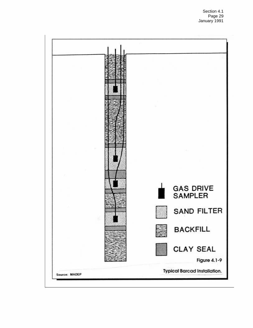
o Barcad Systems
The Barcad system utilizes gas driven samplers and tubes positioned
at selected depths in a single borehole (Figure 4.1-9). The samplers are connected to the surface by a gas drive tube through which a sample is collected (Figure 4.1-10). The samplers are isolated by bentonite seals. Although the system is similar to the stacked standpipe system, the relatively small diameter tubes allow a more effective seal to be installed between monitoring zones.
o Advantages
Allows for installation of a multi-level well in a single borehole;
minimizing drilling and well installation time and costs. Allows for determination of potentiometric levels at discrete depths
within aquifer Smaller inside diameters reduce the need for purging large volumes
of water prior to sampling

Section 4.1 Page 17
January 1991
o Disadvantages
In most cases systems require specialized equipment and a trained
field technician for sampling. Packers on the Waterloo system are self inflating (water-activated).
May be a problem when installing in deep (greater than 300 feet) boreholes.
Small tubes in the Barcad- and Waterloo-type systems may become
damaged or crimped during installation. Also, water levels may be difficult to measure due to the small diameter of the tubing.

Section 4.1 Page 18
January 1991
REFERENCES Barvenik, M. and Cadigan, R., 1980, Barcad Groundwater Sampling Systems, Technical
Bulletin 80-3. Cherry, J., 1988, A Field Perspective on Groundwater Contamination given at University
of Southern Maine, Gorham, Maine. Massachusetts Department of Environmental Protection, Massachusetts Contingency
Plan: available from the State House Bookstore, Boston, Massachusetts as 310 CMR 40.000, p. 48.
__________ 1988, Draft interim guidance for chapter 21E disposal site risk
characterization: available from the State House Bookstore, Boston, Massachusetts, as Document #70.
Schwille, F., 1988, Dense chlorinated solvents in porous and fractured media, model
experiments: Chelsea, MI, Lewis Publishers, Inc., trans. by Pankow, J.E., p. 146. Solinist, Waterloo Multilevel Groundwater Monitoring System, Data Sheet 401, Solinst
Canada Ltd., Burlington, ON, Canada. U.S. EPA, 1989, Seminar Publication: Transport and Fate of Contaminants in the
Subsurface, Center for Environmental Research Information, Cincinnati, OH, Document EPA/625/4-89/019, p. 148.
Westbay Instruments Inc., Multiple-level Groundwater Monitoring Wells, North
Vancouver, BC, Canada.
ADDITIONAL REFERENCES Driscoll, F., 1986, Groundwater and wells: St. Paul, MN, Johnson Division, 1089 p. Powers, J. P., 1981, Construction dewatering: New York, NY, John Wiley & Sons, Inc.,
484 p. Todd, D.K., 1980, Groundwater hydrology, 2nd edition: New York, NY, John Wiley &
Sons, Inc., 535 p.

Section 4.1 Page 19
January 1991
SECTION 4.1 MONITORING WELL NETWORK DESIGN
LIST OF FIGURES
Figure Title Page No. 4.1-1 Geologic Cross-section.......................................................................... .18 4.1-2 Ground Water Contour Map .................................................................. .18 4.1-3 Sketch of Floating Contaminant............................................................... 19 4.1-4 Illustration of Sinking Contaminant in a Porous Material....................................................................................... 20 4.1-5 Illustration of Sinking Contaminant in Fractured Bedrock .................................................................................. 21 4.1-6 Basic Well Types ..................................................................................... 22 4.1-7 Waterloo Multilevel Monitoring Well Detail .............................................. 23 4.1-8 Westbay Multilevel Well ........................................................................ .24 4.1-9 Typical Barcad Installation ...................................................................... 25 4.1-10 Detail of a Barcad Sampler...................................................................... 26

Section 4.1 Page 20
January 1991

Section 4.1 Page 21
January 1991

Section 4.1 Page 22
January 1991

Section 4.1 Page 23
January 1991

Section 4.1 Page 24
January 1991

Section 4.1 Page 25
January 1991

Section 4.1 Page 26
January 1991

Section 4.1 Page 27
January 1991

Section 4.1 Page 28
January 1991
Section 4.1 Page 29
January 1991

Section 4.1 Page 30
January 1991

COMMONWEALTH OF MASSACHUSETTS DEPARTMENT OF ENVIRONMENTAL PROTECTION STANDARD REFERENCES FOR MONITORING WELLS SECTION 4.2 SELECTION OF WELL CONSTRUCTION MATERIALS

Section 4.2 Page i
January 1991
SECTION 4.2 SELECTION OF WELL CONSTRUCTION MATERIALS
TABLE OF CONTENTS
Section Title Page No. 4.2-1 PURPOSE ................................................................................................ 1 4.2-2 CASING MATERIALS ......................................................................................... 2 4.2-2.1 Composition.............................................................................................. 2 4.2-2.1.1 Polyvinyl Chloride .................................................................................... 2 4.2-2.1.2 Stainless Steel .......................................................................................... 3 4.2-2.1.3 Teflon ....................................................................................................... 4 4.2-2.2 Size .......................................................................................................... 4 4.2-3 WELL SCREEN SELECTION................................................................... 5 4.2-3.1 Slot Size.................................................................................................... 5 4.2-3.2 Style.......................................................................................................... 5 4.2-3.2.1 Slotted Pipe ............................................................................................. 6 4.2-3.2.2 Wire-wound, Continuous Slot Pipe .......................................................... 6 4.2-3.3 Sediment Sump ........................................................................................ 7 4.2-4 FILTER PACK........................................................................................... 7 4.2-4.1 Washed Sand ........................................................................................... 8 4.2-4.2 Uniformly-graded Silica Sand .................................................................. 8 4.2-5 SEALS ....................................................................................................... 9 4.2-5.1 Surface Seal (aprons)............................................................................... .9 4.2-5.2 Divider Seal .............................................................................................. 9 4.2-5.3 Bedrock Seal .......................................................................................... 10 4.2-5.4 Annular Seal ......................................................................................... .10 4.2-6 SEALING MATERIALS.......................................................................... .10 4.2-6.1 Solid Well Sealants. ................................................................................ 10 4.2-6.1.1 Bentonite Pellets...................................................................................... 10 4.2-6.1.2 Coarse-grade Bentonite Chips ............................................................... 11

Section 4.2
Page ii January 1991
SECTION 4.2
SELECTION OF WELL CONSTRUCTION MATERIALS
TABLE OF CONTENTS (continued)
Section Title Page No. 4.2-6.2 Grout Seals............................................................................................. 11 4.2-6.2.1 Cement-based Grouts ............................................................................ 11 (a) Neat Cement ................................................................................... 12 (b) Neat Cement with Bentonite............................................................. 12 (c) Concrete............................................................................................. 12 (d) Cement Additives ............................................................................... 13 4.2-6.2.2 Bentonite-based Grouts ......................................................................... 13 (a) Heavy Bentonite Grout ...................................................................... 13 (b) High-solids Bentonite Grout .............................................................. 13 (c) Granular Bentonite Slurries ............................................................... 13 4.2-7 PROTECTIVE CASINGS ....................................................................... 14 4.2-7.1 Above-ground Protective Casing ........................................................... 14 4.2-7.2 Flush-mount or Road-box Casing .......................................................... 14 REFERENCES .............................................................................................................. 16 ADDITIONAL REFERENCES ........................................................................................ 17

Section 4.2 Page iii
January 1991
LIST OF FIGURES Figure Title Page No. 4.2-1 Well Component Diagram ...................................................................... 20 4.2-2 Types of Well Screen Slots .................................................................... 21 4.2-3 Diagram of a Sediment Sump ................................................................ 22 4.2-4 Above-ground Protective Casing ........................................................... 23 4.2-5 Flush-mount Road-box .......................................................................... 24 4.2-6 Manhole-type Road-box ......................................................................... 25 4.2-7 Protective Posts Around a Monitoring Well ............................................ 26
LIST OF TABLES Table Title Page No. 4.2-1 Basic Well Casing and Screen Material Composition............................................................................................. 27 4.2-2 Volume of Water in Casing or Hole ......................................................... 28 4.2-3 Total Slot Area of Screen of Various Gauges in Square Inches per Foot .......................................................................... 29 4.2-4 ASTM Cement Designations .................................................................. 30 4.2-5 Properties of Neat Cement Slurries ........................................................ 31 4.2-6 Grout Properties - Advantages and Disadvantages ................................ 32

Section 4.2 Page 1
January 1991
SECTION 4.2 SELECTION OF WELL CONSTRUCTION MATERIALS
4.2-1 PURPOSE The purpose of this Standard Reference (SR) is to provide guidance for selecting the most economical and chemically inert monitoring well construction materials. While there are many similarities with the process of selecting materials for water wells, there are also major differences that may be significant, especially in a highly contaminated environment. Monitoring well casing and well construction materials should be selected to meet the following criteria:
o The materials should be resistant to deterioration resulting from long-term exposure to natural or synthetic chemical constituents in the ground water at the site.
o The materials must have sufficient strength to ensure the structural integrity of
the well during installation and long-term monitoring.
o The materials should be selected to minimize their interference with the measurement of specific chemical parameters expected to be found at a site.
o The casing diameter should be large enough to accommodate commercially
available down-hole instrumentation or sampling equipment (e.g., oil/water interface probe), but also small enough to minimize the volume of water to be purged from the well.
o The well casing should be watertight.
o The well must be able to be secured against vandalism, leakage, and inadvertent
damage.
o The screen and filter pack must be appropriately sized to provide representative data on hydraulic conductivity and ground water quality.
This section provides guidance for the selection of materials commonly used in monitoring well installations, and discusses the advantages and disadvantages of each. Figure 4.2-1 depicts the basic materials comprising a monitoring well: casing or riser, screen, filter pack, seals, and protective casing. The selection of well construction materials should be site-specific. Proper selection requires consideration of the project objectives, compliance with regulatory requirements, available data about the site geology, water chemistry, and the project budget. Section 4.1 Network Design describes important considerations for designing a good monitoring well. Well installation procedures are discussed in Section 4.3, and Section 4.4 discusses the minimum requirements for As-built Notes and Records of monitoring wells. New well materials, filter packs and sealants are continually being developed. Individuals involved in well design and installation should be aware of recent developments in monitoring well technology.

Section 4.2 Page 2
January 1991
Ground Water Monitoring Review, a quarterly publication of the National Water Well Association, is a useful source of innovative and improved monitoring techniques. Another valuable source of information on the availability and feasibility of using various well materials is a drilling contractor experienced in monitoring well installation. Experienced drilling contractors are capable of providing insight into the compatibility of various well construction materials with a particular drilling technique, as well as information on the amount of time an installation may require, and potential problems that particular materials may present during installation. 4.2-2 CASING MATERIALS The casing, or riser, is the part of the well that extends from the top of the well screen to the ground surface (see Figure 4.2-1). When selecting well casing and screens, both the composition and diameter must be taken into consideration. 4.2-2.1 Composition There are a number of commercially available well casing materials. The advantages and disadvantages of only a few of the most commonly used materials are described below. It is possible to combine different materials as long as they are compatible. There is considerable debate over the significance of the adsorption and desorption potential of many well casing materials. However, adequate purging of the well prior to sampling reduces or eliminates the potential for this to have a significant impact on sample chemistry. If in doubt about the suitability of a particular casing for a ground water problem, it is advisable to consult chemical compatibility charts or the manufac-turer for additional information. The significance of the adsorption-desorption problem must be evaluated based on the monitoring well program objectives, sampling and analytical requirements, and the concentrations one is trying to measure. 4.2-2.1.1 Polyvinyl Chloride (PVC) Polyvinyl chloride (PVC) is the most common well casing material used in monitoring well construction. PVC is thermoplastically molded casing composed of a rigid, unplasticized polymer. PVC casing offers a combination of chemical resistance, dura-bility, availability, and low cost. There is considerable debate over the reaction of PVC well casing with some ketones, aldehydes, and chlorinated solvents. In some cases, PVC has been shown to adsorb and desorb low levels of organic compounds. Flush-threaded or coupled PVC casing should be used for monitoring well construction. If flush-threaded casing is used, ASTM specified thread specifications should be used. Under NO circumstances should solvent cement be used to join casing sections together. PVC solvent cements have been shown to contribute significant quantities of organic contaminants to water samples collected from cemented PVC wells. Generally, flush-threaded casing is preferred due to the ease of installation and because, if properly joined, it provides a water-tight seal. For all monitoring well applications where PVC is selected, only PVC well casing listed with the National Sanitation Foundation (NSF) should be used. These products are essentially free of readily leachable plasticizers and do not exceed the National Interim Primary Drinking Water Standards in leach tests.

Section 4.2 Page 3
January 1991
Advantages
o Excellent chemical resistance to weak alkalis, alcohols, aliphatic hydrocarbons, and oil and grease.
o Good chemical resistance to strong mineral acids, strong oxidizing acids, and
strong alkalis.
o Readily available.
o Lightweight.
o Inexpensive.
o Two wall thicknesses commonly available (Schedule 40 and 80) provide a choice of strengths.
Disadvantages
o May adsorb and desorb low levels of some organic constituents from the
ground water. This may not be a problem if the well is adequately purged prior to sampling.
o Poor chemical resistance to concentrated ketones, esters, and some
aromatic hydrocarbons.
o Weaker, less rigid, and more temperature-sensitive than metallic casing materials.
4.2-2.1.2 Stainless Steel Stainless steel provides an excellent casing material where corrosion resistance and strength are important. The strength provided by stainless steel may be essential when installing wells in deep boreholes (over 300 feet deep) due to the potential for other casing materials with lower strengths to collapse. Stainless steel is resistant to most chemicals and is suitable for monitoring many types of contaminants. Long periods of exposure to highly corrosive ground water conditions may result in leaching of chromium or nickel from stainless steel well casing. Therefore, if the pH of the ground water is low (4 or less), stainless steel is not recommended for long-term monitoring of inorganic constituents. Stainless steel is available in a variety of types, each with a slightly different composition. The basic composition and suggested applications for various types of stainless steel and other metals for well casing and screens is presented in Table 4.2-1. As with PVC, stainless steel casing should have threaded, flush joints to assure watertight connections.

Section 4.2 Page 4
January 1991
Advantages
o Excellent resistance to corrosion and oxidation; will not adsorb or desorb organic contaminants.
o High strength, rigidity.
o Suitable for wide range of temperatures.
o Readily available.
Disadvantages
o Susceptible to galvanic and electrochemical corrosion. o Heavy; may require additional equipment to lower down borehole. o May leach chromium and/or nickel in acidic waters. o Moderate to high cost.
4.2-2.1.3 Teflon Teflon is a fluorocarbon polymer developed by Dupont. Teflon displays a high resistance to chemical attack, reportedly low adsorption of chemicals, and low leaching of the casing compounds. Most Teflon materials available for monitoring well applications have been manufactured specifically for ground water monitoring applications. Advantages
o High resistance to chemical attack. o Very limited adsorption capacity. o Low potential for leaching. o Lightweight.
Disadvantages
o Low tensile strength and rigidity. o Tendency towards excessive slippage during installation. o Limited availability. o In deep installations slots in screen may close under the weight of the riser. o Comparatively high cost.
Section 4.2 Page 5
January 1991
4.2-2.2 Size The size of the well casing, both the wall thickness and the inside diameter (ID) of the pipe, is a consideration when selecting well construction materials. The wall thickness determines the strength of the casing material, and the inside diameter must provide enough room for downhole instrumentation. The thicker the casing, the stronger the pipe. Pipe or casing thickness is described in various "schedules." For PVC monitoring well applications, Schedule 40 and Schedule 80 are commonly used. Schedule 80 is thicker and stronger than Schedule 40. Metal casing materials also come in various wall thickness, or schedules. Monitoring well casing materials are available in 3/4-, 1-1/2-, 2-, 4- and 6-inch ID sizes. With the exception of specialized installations such as Barcads, Westbay, and others, a minimum inside diameter of 2 inches is recommended by DEP for all standard monitoring well installations. This minimum diameter does not apply to piezometers, which are only to be used for water-level measurements or qualitative sample analysis. Two-inch ID wells will accommodate most commercially available sampling pumps, bailers, and transducers. In some applications larger diameter wells may be desirable so that standard pumps and skimmer systems can be used. It should be noted that large diameter wells (4-inch and greater) may require substantially longer purging time before a sample can be collected and will produce large volumes of purge water. The volume per linear foot of casing is directly proportional to the square of the casing diameter. Table 4.2-2 shows the volume of water contained in casings or holes of various diameters. The selection of the size of the well casing will also influence the size of the borehole needed for proper installation of the well screen and casing, and the quantity of filter pack and seal needed. As described in Section 4.3 Installation of Wells, ideally the diameter of the borehole should be at least 4 inches greater than the outside diameter of the well screen and the riser pipe. 4.2-3 WELL SCREEN SELECTION A well screen is a filtering device that serves as the intake portion of wells constructed in unconsolidated or semiconsolidated aquifers. The screen provides a hydraulic connection to the saturated aquifer so that representative water level and chemical data can be obtained. It permits water to enter the well from the saturated aquifer, prevents sediments from entering the well, and serves to structurally support the unconsolidated aquifer material. The considerations of composition, resistance to corrosion, sufficient column and collapse strength, and inside diameter for well-screens are the same as for well casings; however, the strength of the screened section is less than that of the riser sections due to the openings. Additional screen criteria and functions that should be considered are slot size (i.e., percentage of open area) and style (i.e., non-clogging slots).

Section 4.2 Page 6
January 1991
4.2-3.1 Slot-size Well screens are categorized based on the width of the openings in thousandths of an inch. No. 10 slot, for example, represents an opening of 0.010 inch. Generally a 10-slot or 20-slot (0.010- or 0.020-inch, respectively) screen is appropriate for monitoring wells where low pumping rates are used. Obviously, it is important that the filter pack around the screens be larger than the screen slots to prevent infiltration of the pack during purging and sampling. Slot-size selection is also important if the well is to be used for field permeability tests in coarse-grained materials where a small slot size might have a lower hydraulic conductivity than the native soils. Also, in situations where highly viscous materials (i.e., heavy oils or creosote) are being monitored, a large slot size is preferred to avoid inhibiting flow through the screen. The spacing of the slots may be varied also, if desired. 4.2-3.2 Style Two types of standard well screens are commercially available for monitoring well construction: slotted pipe and wire wound continuous slot (see Figure 4.2-2). Hand-cut or hand-slotted screens are not sufficiently uniform to produce a satisfactory well screen; they should never be used for monitoring wells. 4.2-3.2.1 Slotted Pipe Slotted pipe consists of standard well casing that has been machine perforated with parallel rows of slots. The size, frequency and configuration of the slots will vary with the application and manufacturer. In general, slotted screens have approximately 5 to 10 percent open area. Table 4.2-3 shows the total slot area of screens of various gauges in square inches per foot. Advantages
o Machine-manufactured - good slot size control. o Readily available. o Inexpensive.
Disadvantages
o Limited open area; this may inhibit efficient well development. o Prone to clogging by fines.

Section 4.2 Page 7
January 1991
4.2-3.2.2 Wire-wound, Continuous Slot Pipe Wire-wound, continuous slot screens provide a larger open area than slotted screens, typically twice as much. Wire-wound screens consist of triangular-shaped, continuously wound wire connected by vertical bars. The V-shaped openings are wider on the inside than the outside, reducing the likelihood of clogging by formation materials. Advantages
o Good slot control; wide range of sizes available.
o Larger percentage of open area than slotted screens.
o Large open area allows fluid to enter at a low velocity, reducing the turbidity of sample.
o Less susceptible than slotted pipe to plugging due to V-shaped slots.
Disadvantages
o More expensive than screens made of slotted pipe. PVC-wound screen is commercially available and has the same advantages as the wire-wound screen. This product is not generally recommended because it is more expensive than the slotted PVC pipe and has a low collapse strength. 4.2-3.3 Sediment Sump In formations of fine sand, silt, or clay it may be difficult to completely prevent the migration of fines through the filter pack and screen. Where suspended fines are a problem, the monitoring well can be constructed with a sediment sump below the screened zone to collect the fines. An example of a sediment sump is shown in Figure 4.2-3. If a sediment sump is employed, one must be careful that the accumulated fines are not disturbed and suspended during purging or sample collection. If a submersible pump is used, it should be placed a substantial distance above the sump to avoid becoming clogged by fines that have collected in the sump. 4.2-4 FILTER PACK A filter pack around the screen helps to reduce the movement into the screen of fine-grained materials that could potentially clog the screen and inhibit water movement. In addition, the filter pack provides support around the well screen to prevent the formation materials from collapsing around the screen. An effective filter pack provides a zone of high hydraulic conductivity around the screen and reduces the infiltration of fines. The filter pack must be chemically inert; otherwise, it may affect the chemistry of the ground water as it passes through the pack and into the well.
Section 4.2 Page 8
January 1991
When monitoring wells are installed in formations with a wide range of particle sizes, effective filtration can be difficult. Filter packing procedures recommended for water wells are not suitable for monitoring wells, unless the hydraulic characteristics of the formation materials are similar to those of an aquifer (i.e., thick deposits of coarse sand and fine to medium gravel). To exclude the entrance of fine silts, sands, and clays into a monitoring well, the grain-size distribution curve for the filter pack ideally is selected by multiplying the 50-percent retained size of the finest formation sample by 2. This approach may not be practical in fine-grained materials (i.e., silts and clays). This leads to a more conservatively sized filter pack than would be selected for a water supply well. Uniformity coefficients should range from 2 to 3 (Driscoll, 1986). All filter pack material should be purchased from reputable suppliers who have properly cleaned and bagged the material. The importance of the cleanliness of the filter pack should be emphasized. Typically, washed sand or silica sand is used for filter packs around monitoring well screens. In some uniform, coarse-grained formations the native soil materials are allowed to collapse around the screen, providing a suitable, natural filter pack. According to Gass (1988), monitoring wells should be filter-packed under the following circumstances:
o When there is more than 10 to 15 percent clay-/or silt-sized particles in the formation.
o When the well is completed in a formation consisting of relatively fine uniform
sand.
o When the physical characteristics of the formation in the screened zone are highly variable.
o When the formation is composed of friable or fractured rock, which allows
sand, silt or clay to enter the well.
o When the formation is not an aquifer. The amount of filter pack ordered should be sufficient to enable the filter pack to be as thick as practical, particularly in low permeability soils. Oversized borehole diameters are recommended for monitoring wells screened in silt and clay soils to accommodate a large volume of filter pack. Two types of filter packs are discussed below. 4.2-4.1 Washed Sand Washed sand typically consists of concrete or mortar sand that has had only the fine particles removed by washing and screening. Washed sand is usually available in different size ranges. This material is generally available in bulk quantities. The quality assurance and control of this type of material should be reviewed. Lack of QA/QC is often a limiting factor for use as a monitoring well filter sand. A representative sample should be collected during drilling for analysis at a later date should concerns arise over the quality of the material.

Section 4.2 Page 9
January 1991
Advantages
o Inexpensive. o Wider range of grain sizes than silica sand o Readily available.
Disadvantages
o Chemical composition and reaction with ground water usually not known.
o In deep boreholes particle-size segregation may occur during free-fall installation. Proper installation may require emplacement with a tremie pipe.
o Lack of QA/QC for this source. 4.2-4.2 Uniformly-graded Silica Sand Uniformly graded silica sand is manufactured by crushing quartzite into small particles. It is manufactured for sandblasting and can be purchased in bags. It is available in a variety of grain-sizes, but it is usually more uniform in size than washed sand. Its angularity is greater than that found in most washed sands. Ottawa sand is a brand name for silica sand that comes from Ottawa, Illinois. Ottawa sand is more rounded and spherical than other silica sand products. It is frequently specified for monitoring well installations, but it is much more expensive than locally manufactured silica sand with the same specifications. These products generally have acceptable QA/QC for use as a filter sand for monitoring wells. Advantages
o Composition is essentially pure silica; as such, it is chemically inert. o Generally has acceptable QA/QC.
o Readily available in bags. o Easy to install.
Disadvantages
o More expensive than washed sand.
o Fine-grained silica sand sizes may be slow to settle; may increase installation time or require installation by tremie pipe.

Section 4.2 Page 10
January 1991
4.2-5 SEALS An effective monitoring well seal prevents the vertical movement of ground water within the borehole and should not interfere with the water chemistry of the aquifer. The purpose of installing a monitoring well seal is to:
o Seal off and isolate a specific section of an aquifer to obtain information on the hydrogeologic and chemical characteristics at that location.
o Prevent migration of fluids from the ground surface into the borehole.
o Prevent contaminant movement from one section of an aquifer to another or
between aquifers, especially to make sure that contaminated ground water does not enter contaminant-free geologic formations.
o Provide support for the well casing and prevent collapse of the borehole walls.
There are four types of seals used in monitoring well installations: surface seals, divider seals, bedrock seals, and annular seals. 4.2-5.1 Surface Seal (Apron) A concrete seal around the top of the well is recommended even if the annular seal is carried to the surface. This concrete apron or seal should be shaped so that surface water flows away from the casing. Bentonite is not an acceptable material for surface seals because it will dehydrate and crack resulting in poor sealing properties. Based on the average depth of frost penetration in Massachusetts the surface seal should, if possible, extend a minimum of four feet below ground to prevent frost-heaving of the apron. 4.2-5.2 Divider Seal A divider seal consists of a layer of bentonite slurry or pellets designed to prevent the liquid grout seal from plugging up the filter pack. This seal should be placed above the filter pack and below the annular seal. The minimum acceptable thickness is 6 inches; the recommended thickness is 2 feet. 4.2-5.3 Bedrock Seal All open bedrock monitoring wells should be grouted, sealing the casing into the rock. A special exception to this rule is the case where the bedrock interface itself is being monitored.

Section 4.2 Page 11
January 1991
4.2-5.4 Annular Seal Annular seals are placed in the annular space above the divider seal to plug up the open space between the well casing and the borehole wall. It is extremely important that this seal consists of a low permeability material that will serve to inhibit the vertical movement of fluids within the borehole. If the well casing is in direct contact with the borehole wall it will not be possible to install an annular seal. A tight fit between the well casing and the borehole wall should serve to prevent the vertical movement of fluids along the outer wall of the casing. In certain specialized installations, such as Barcads, the annular seal consists of a 2-foot thick layer of bentonite pellets placed above and below the porous Barcad sampler. The importance of the annular seal becomes extremely significant when the well owner is ready to decommission the monitoring well. If the well owner can demonstrate that the monitoring well was properly sealed originally, decommissioning will be a much simpler and less costly procedure (see Section 4.6 Well Decommissioning). An annular seal is generally composed of one or a combination of the following sealants: neat cement, bentonite/cement slurries, or equivalent sealing agents. 4.2-6 SEALING MATERIALS There are several types of sealants available for monitoring well installations. The selection of a well sealing material will depend on the depth of application, the chemistry of the water, the well casing material, and the purpose of the well program. Well sealants can be divided into two basic categories: solid sealants and grout sealants. These sealants are described below. 4.2-6.1 Solid Well Sealants These materials are installed in a well bore in a solid form. Solid sealants are usually applied as divider seals between the filter pack and the annular seal or as the only seal in specialized installations. 4.2-6.1.1 Bentonite Pellets Bentonite pellets consist of pre-formed pellets, usually ¼- to ½-inch in diameter; they are made from compressed sodium bentonite clay. When the pellets are hydrated with clean water, they swell to about 10 to 15 times their original volume. Because they hydrate rapidly, the pellets are prone to stick between the borehole wall and well casing (i.e. bridge) before reaching the bottom if they are manually dropped down the annular space. Advantages
o Readily available. o Provide a solid seal that can be immediately measured during installation.
Disadvantages
o Tendency to stick can make them difficult to install.

Section 4.2 Page 12
January 1991
o Installation can be slow in deep borings. 4.2-6.1.2 Coarse-grade Bentonite Chips Coarse-grade bentonite consists of large chips of bentonite, usually 3/8- to 1-inch in size, resembling pea stone in appearance. Similar to bentonite pellets, bentonite chips will hydrate and expand when exposed to clean water. They are primarily intended for borehole decommissioning purposes but have been used as divider seals and shallow annular seals in monitoring wells. Due to their coarse grain-size, this material has limited use in monitoring well installations. Chips are not suitable for installation in small diameter holes because bridging may occur. Prior to installation, the chips should be sifted to remove the fines since, if the fines are not removed, they will clump as they hit the water and increase the chance of bridging (Gaber and Fisher, 1988). Advantages
o Provides a solid seal; its position can be verified by measurement immediately after installation.
o Inexpensive.
o Simple to install.
Disadvantages
o Not suitable for small diameter boreholes. o Needs to be sorted. o Prone to bridging. o Relatively new product; further field testing needed.
4.2-6.2 Grout Seals Grout is a mixture of powdered cement and/or bentonite and water to create a pumpable fluid. In some applications, aggregates and chemical additives are added to the mix to enhance the properties of the grout or to alter the setup rate. In monitoring well applications, grouts are typically installed as an annular seal between the monitoring well casing and the borehole wall. There are two basic types of grouts that are used as monitoring well seals: cement-based grouts and bentonite-based grouts. The applications, advantages, and disadvantages of these grouts are discussed below.

Section 4.2 Page 13
January 1991
4.2-6.2.1 Cement-based Grouts Cement-based grouts consist of a mixture of Portland cement and water. The sealant qualities of cement-based grouts are related to the type of cement that is used, the water-to-mix ratio, mixing methods, and installation methods. The rate at which a cement-based grout will set is principally related to the chemical composition of the cement. Generally, Portland Type I or II cement is used for monitoring well seals. Table 4.2-4 summarizes the characteristics of the different ASTM cement types. A by-product of the chemical reactions that result in hardening of the cement is heat. The amount of heat that is produced during hydration is related to the chemical composition of the cement, the thickness and total volume of grout emplaced, and the ambient formation temperatures (Gaber and Fisher, 1988). The heat of hydration should be considered when grouting boreholes with plastic casing, especially in deep applications. There are three types of cement-based grouts used in monitoring well applications: neat cement, neat cement with bentonite, and concrete. (a) Neat Cement: Neat cement is a mixture of powdered cement and water; no sand or aggregate
is added to the mix. The sealing qualities of neat cement depend on the water-to-cement mix ratio. Table 4.2-5 presents the properties of neat cement based on the gallons of water per bag of cement. All neat cement shrinks as it sets, and shrinkage increases with the water content of the cement mix. Consequently, the addition of too much water will adversely affect the sealant properties. Even properly mixed, a pure neat cement will shrink approximately 18 to 20 percent as it sets (Williams and Evans, 1987). Due to this excessive shrinkage, pure neat cement has limited application as a monitoring well sealant.
(b) Neat Cement with Bentonite: The addition of a small amount of bentonite to a neat cement slurry will improve
the sealing properties of the grout by reducing the shrinkage and separation of the concrete materials in the borehole. The addition of bentonite also decreases the density of the mix and increases the viscosity and fluidity. Although the addition of bentonite reduces the shrinkage and increases the pumpability of the grout, it also results in a decrease in the final strength of the grout and may increase its vulnerability to chemical attack (Williams and Evans, 1987). Generally, a mix consisting of between 5 and 15 percent bentonite is desirable.
While it is recommended that the proportion of bentonite be limited to
approximately 5 percent or less, some very porous materials (e.g., coarse gravel) may require more bentonite to reduce the loss of grout into the formation.
Section 4.2 Page 14
January 1991
(c) Concrete: Concrete is a mixture of Portland cement, sand, and water. The addition of the
aggregate to the neat cement grout increases the strength of the material, reduces the shrinkage, and typically results in tighter bonding compared to neat cement grouts. Concrete is typically used for the surface seal in a monitoring well installation. Concrete is generally used to cap grout or bentonite seals because it is less prone to cracking and is easy to mix. Concrete is not suitable as a sealant for annular spaces because it has a tendency to separate in water, may bridge during installation, and is difficult to pump.
(d) Cement Additives: In some instances, chemical additives can be mixed with the grout to accelerate
the rate of setup. Calcium chloride is the most common cement accelerator, and is usually added in quantities of two to four percent by weight (Gaber and Fisher, 1988). Although accelerators have application in emergency grouting operations, they are not recommended for use in monitoring well installations due to their impact on water chemistry.
4.2-6.2.2 Bentonite-based Grouts Bentonite is a montmorillonite clay that will expand 10 to 12 times in size upon hydration (Gaber and Fisher, 1988). There are both sodium- and calcium-rich varieties of bentonite. Sodium-rich bentonite is preferred for monitoring well applications because of its superior expansive qualities. Bentonite-based drilling muds have been used for many years in the water well industry, but only in the past decade has there been research into the use of bentonite grouts as permanent seals in monitoring wells. There are basically three types of bentonite-based grouts: heavy bentonite grout, high-solids bentonite grout, and granular bentonite grout.
(a) Heavy Bentonite Grout: Heavy bentonite grout consists of a mix of bentonite and water, consisting of
10 percent bentonite by weight. The grout must have a high density and high gel strength in order to be effective. The proper bentonite-to-water mix will result in a high viscosity fluid that can be difficult to pump. Improper mixing or installation can result in the bentonite settling out of settling of the water. Due to their difficult mixing and pumping requirements, heavy-bentonite grouts have limited application for monitoring well installations.

Section 4.2 Page 15
January 1991
(b) High-solids Bentonite Grout: High-solids bentonite grout consists of a mix of bentonite, water, and an initiator
to produce a grout that is 15- to 20-percent solids. The addition of the initiator, usually magnesium oxide, is required to obtain the high percent of solids. Mixing is more complex than with other grouts. High-solids bentonite slurries require a Venturi-jet mixer, mud-rotary pump, or a paddle mixer to produce a suitable mix (Gaber and Fisher, 1988). Properly mixed high-solids bentonite grouts are easy to pump and provide a flexible, low-permeability seal. This material sets up into a plastic clay putty in approximately 8 to 24 hours. Generally, a solid seal of cement or solid bentonite is required at the base and the top of this grout.
(c) Granular Bentonite Slurries: Instead of powdered bentonite, granular bentonite slurries utilize bentonite
particles ranging from 8- to 20-mesh in size (Gaber and Fisher, 1988). The comparatively smaller surface area of the granular bentonite results in a slower rate of adsorption. A proper granular bentonite slurry mix should contain 15- to 20-percent bentonite by weight. In order to obtain a pumpable mix of 15- to 20-percent bentonite, a synthetic organic polyacrymide polymer is sometimes added to suppress hydration and delay swelling. The addition of synthetic polymers is NOT recommended for the installation of monitoring wells unless prior approval is obtained from DEP. Similar to high-solids grouts, granular bentonite grouts require a blade or paddle mixer; a centrifugal pump is not capable of mixing this grout. An advantage of the granular grout mix is that, unlike other bentonite grouts, it provides mechanical stability to the casing and borehole walls (Gaber and Fisher, 1988). Granular slurries can be difficult to install, due to problems resulting from premature expansion of the bentonite.
Table 4.2-6 provides a comparison of the advantages and disadvantages of
cement-based and bentonite-based grouts. 4.2-7 PROTECTIVE CASINGS A protective well casing is required for all monitoring wells to protect the well from damage, leakage, tampering, and vandalism. Protective well casings are generally constructed of steel and have a locking cap. Two basic types of protective casings are used in monitoring well installation: an above-ground casing and a flush-mount casing, or road box (see Figures 4.2-4 through 4.2-6). 4.2-7.1 Above-ground Protective Casing Above-ground protective well casings are typically constructed from steel or cast iron pipe sections, generally 5 to 7 feet in length and 4 inches or greater in diameter. Iron or steel protective casings are much preferred over plastic because they are less susceptible to damage and vandalism. If the protective casing has a screw-on cap, making it air-tight, the protective casing as well as the riser pipe should be vented with a small hole. The protective casing should have a hasp on the top so it can be locked with

Section 4.2 Page 16
January 1991
a padlock. The padlock should be corrosion-resistant; it is advisable that all the padlocks at a site be keyed alike for simplicity. In some heavily trafficked areas, the protective casing may be subject to damage by vehicles or snowplows. Additional posts or casings should be installed to provide a buffer zone around the well (Figure 4.2-7). Three posts placed in a triangle, each about two feet from the well, should be sufficient. Fewer posts may be necessary if the traffic pattern is well defined. 4.2-7.2 Flush-mount or Road-box Casing A flush-mount protective casing is used where the well installation must be installed flush with the ground surface, such as in roadways, parking lots, and sidewalks. Flush-mount well installations also help to disguise the well location and reduce the potential for vandalism. As shown on Figure 4.2-5, the flush-mount installation can be installed with single riser and a valve-box or road-box. Alternatively, a standard type manhole can be installed directly over the well riser pipe with locking protective casing. This type of flush-mount installation is shown in Figure 4.2-6. Generally, manhole covers cannot be locked, so a padlock is placed directly on the protective casing. Some road boxes have a five-sided bolt on the top that holds the cover on. A special wrench is required to open these boxes. A rubber gasket should be placed between the manhole cover and the lip to prevent leakage of surface water into the manhole. When potential high water table conditions exist at flush-mount installations, water tight caps should be placed on top of the riser. If well drained soil conditions exist, granular material should be placed inside the manhole around the well riser to drain surface water that may seep in around the cover. The protective casing must be properly sized for the borehole diameter. Generally, it is best if the protective casing is close to the size of the borehole so that it fits snugly.

Section 4.2 Page 17
January 1991
REFERENCES Driscoll, F. G., 1986, Groundwater and wells, 2nd edition: St. Paul, MN, Johnson
Division, 1,089 p. Gaber, M., and Fisher, B., 1988, Michigan water well grouting manual: Lansing, MI,
Michigan Department of Public Health. Gass, T., 1988, Monitoring well filter pack and screen slot selection: Water Well Journal,
v. 42, no. 6, June 1988, p. 30-32. Johnson Division, 1987, Groundwater monitoring products: St. Paul, MN, Catalog
published by Johnson Division, V.O.P., 12p. Schlumburger, D., 1984, Cementing technology: London, England, Nova
Communications, Ltd., p. 208, cited in a paper by Williams, Camilla and Evans, L.G., 1987, Guide to the selection of cement, bentonite and other additives for use in monitor wells construction: preprint of a paper to be included in Conference Proceedings - NWWA First National Outdoor Action Conference on Geophysical Methods, published by National Water Well Association, Columbus, Ohio.
Williams, Camilla and Evans, L.G., 1987, Guide to the selection of cement, bentonite
and other additive for use in monitor well construction: Las Vegas, Nevada, First National Outdoor Action Conference, May 18-21, 1987.

Section 4.2 Page 18
January 1991
ADDITIONAL REFERENCES Barcelona, M. J., Gibb, J.P., and Miller, R. A., 1983, A guide to the selection of materials
for monitoring well construction and ground water sampling: Champaign, IL, Illinois State Water Survey, ISWS Contract Report 327, 78 p.
Bouwer, H., 1978, Groundwater hydrology: New York, NY, McGraw-Hill Co., 480 p. Brownlee, Dorothy S., 1984, A handbook for ground water contamination problems:
Boston, MA 02108, Mass. Dept. of Environmental Quality Engineering, Division of Hazardous Waste, 92 p.
Cherry, A., 1986, Contaminant migration process-distinguished seminar series on
ground water science: Boston, MA, Day 2, Session 2. National Water Well Association, Selection and installation of well screen and gravel
packs: Worthington, OH. U.S. Environmental Protection Agency, April 1986: REM III program guidelines,
groundwater monitoring well installation: Ebasco Services, Inc. ____________, Manual of ground water quality sampling procedures: Ada, Oklahoma,
Offices of Research and Development, Robert S. Kerr Environmental Research Laboratory, 93 p.
____________, Manual of water well construction practices: Office of Water Supply,
Report EPA-570/9-75-001, 156 pp.

Section 4.2 Page 19
January 1991
SECTION 4.2 SELECTION OF WELL CONSTRUCTION MATERIALS
LIST OF FIGURES
Figure Title Page No. 4.2-1 Well Component Diagram ....................................................................... 20 4.2-2 Types of Well Screen Slots ..................................................................... 21 4.2-3 Diagram of a Sediment Sump ............................................................... .22 4.2-4 Above-ground Protective Casing ............................................................ 23 4.2-5 Flush-mount Road-box ........................................................................... 24 4.2-6 Manhole-type Road-box .......................................................................... 25 4.2-7 Protective Posts Around a Monitoring Well ........................................... .26

Section 4.2 Page 20
January 1991
SECTION 4.2 SELECTION OF WELL CONSTRUCTION MATERIALS
LIST OF TABLES
Table Title Page No. 4.2-1 Basic Well Casing and Screen Material Composition........................................................................................... 27 4.2-2 Volume of Water in Casing or Hole ........................................................ 28 4.2-3 Total Slot Area of Screen of Various Gauges in Square Inches per Foot ......................................................................... 29 4.2-4 ASTM Cement Designations ................................................................. 30 4.2-5 Properties of Neat Cement Slurries ....................................................... 31 4.2-6 Grout Properties - Advantages and Disadvantages ............................... 32

Section 4.2 Page 21
January 1991
Section 4.2 Page 22
January 1991

Section 4.2 Page 23
January 1991

Section 4.2 Page 24
January 1991

Section 4.2 Page 25
January 1991

Section 4.2 Page 26
January 1991

Section 4.2 Page 27
January 1991
Section 4.2 Page 28
January 1991

Section 4.2 Page 29
January 1991
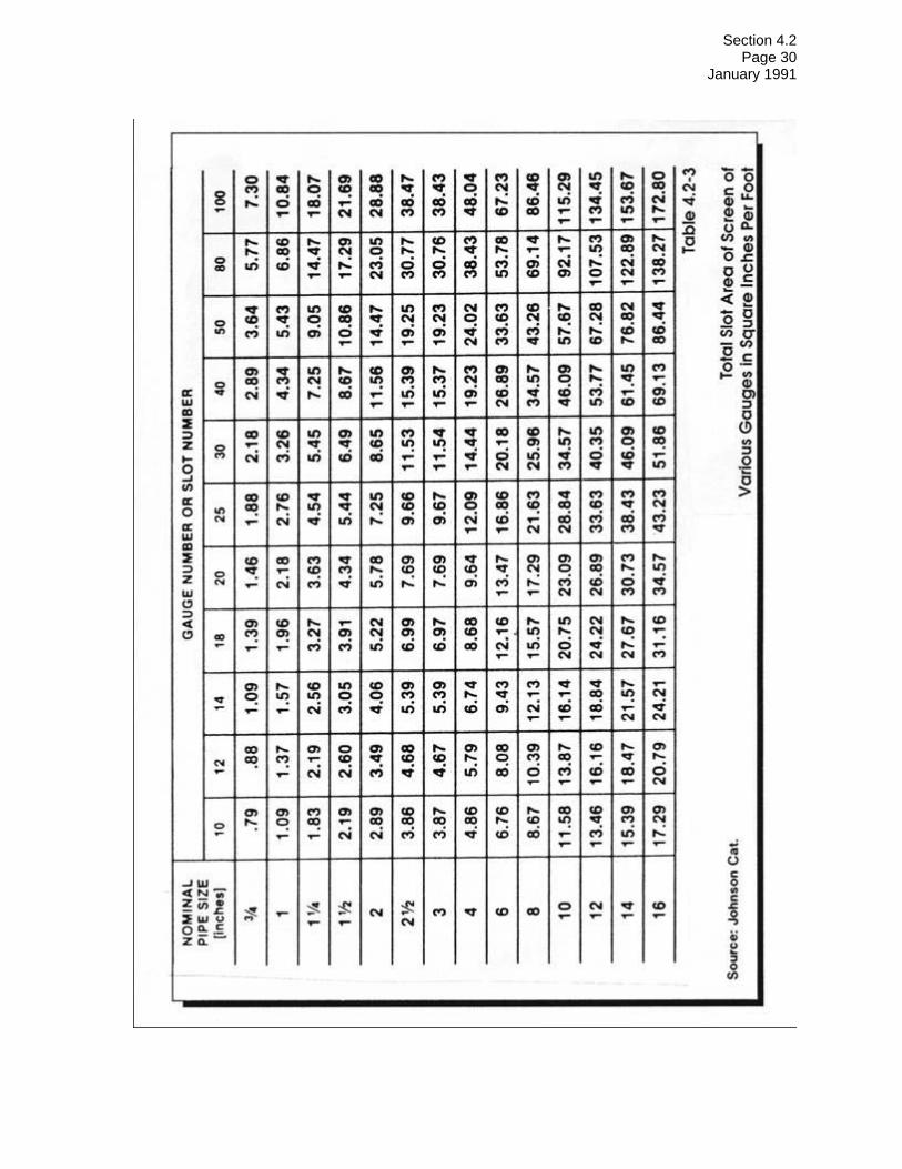
Section 4.2 Page 30
January 1991

Section 4.2 Page 31
January 1991

Section 4.2 Page 32
January 1991
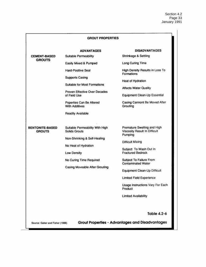
Section 4.2 Page 33
January 1991

COMMONWEALTH OF MASSACHUSETTS
DEPARTMENT OF ENVIRONMENTAL PROTECTION
STANDARD REFERENCES FOR MONITORING WELLS
SECTION 4.3 WELL INSTALLATION PROCEDURES

Section 4.3 Page i
January 1991
SECTION 4.3 WELL INSTALLATION PROCEDURES
TABLE OF CONTENTS
Section Title Page No. 4.3-1 PURPOSE ............................................................................................. . 1 4.3-2 COMPONENTS OF THE INSTALLATION ............................................... 1 4.3-3 INSTALLATION OF SCREEN AND WELL CASING ................................ 2 4.3-3.1 Borehole Preparation................................................................................ 2 4.3-3.2 General Requirements.............................................................................. 3 4.3-3.3 Centralizers............................................................................................... 4 4.3-4 FILTER PACK .......................................................................................... 4 4.3-4.1 General Requirements.............................................................................. 4 4.3-4.2 Installation................................................................................................. 4 4.3-4.2.1 Tremie Method . ........................................................................................ 5 4.3-4.2.2 Freefall and Tamp Method........................................................................ 5 4.3-4.2.3 In-place Filter Pack. ................................................................................. 6 4.3-5 SEALS ................................................................................................... . 6 4.3-5.1 General Requirements.............................................................................. 6 4.3-5.2 Types of Well Seals ................................................................................. 6 4.3-5.2.1 Divider Seals ............................................................................................ 7 4.3-5.2.2 Annular Seals .......................................................................................... 7 4.3-5.2.3 Surface Seals ........................................................................................... 7 4.3-5.3 Installation................................................................................................. 7 4.3-5.3.1 Bentonite Pellets and Slurry ................................................................... . 7 4.3-5.3.2 Grout Slurries............................................................................................ 8 (a) Grout Pumps and Hoses .................................................................. 8 (1) Positive Displacement Pumps ...................................................... 8 (2) Variable Displacement Pumps .................................................................. 8 (3) Pump Hoses ................................................................................................ 9

Section 4.3 Page ii
January 1991
SECTION 4.3 WELL INSTALLATION PROCEDURES
TABLE OF CONTENTS
(continued) Section Title Page No. (b) Grout Mixing......................................................................................... 9 (1) Hand Mixing .................................................................................. 9 (2) Paddle Mixing ................................................................................ 9 (3) Recirculation Mixing ..................................................................... 10 (4) Jet Mixing ..................................................................................... 10 (c) Grout Placement Methods ............................................................... 10 (1) Tremie Method ............................................................................ 10 (2) Surface Pour Method .................................................................. 10 4.3-6 PROTECTIVE CASING AND SURFACE SEAL ...................................... 10 4.3-6.1 General Considerations........................................................................... 10 4.3-6.1.1 Protective Casing Diameter ..................................................................... 11 4.3-6.1.2 Depth of the Protective Casing................................................................ 11 4.3-6.1.3 Surface Seal ............................................................................................ 11 4.3-6.2 Placement of the Protective Casing or Road-box .................................. 11 4.3-6.3 Surface Seal ............................................................................................ 12 4.3-6.4 Identification and Well Security................................................................ 12 4.3-7 PROBLEMS AND POSSIBLE SOLUTIONS ........................................... 12 4.3-7.1 Artesian ................................................................................................... 12 4.3-7.2 Caving Conditions ................................................................................... 13 4.3-7.3 Filter Pack Bridging Between Riser and Casing ..................................... 13 4.3-7.4 Leakage through Road-box ..................................................................... 13 4.3-7.5 Settlement of Protective Casing ............................................................. 14 4.3-7.6 Heavy Traffic ......................................................................................... .14 4.3-7.7 Winter Months ......................................................................................... 14 REFERENCES .............................................................................................................. 15 ADDITIONAL REFERENCES ........................................................................................ 15

Section 4.3 Page iii
January 1991
SECTION 4.3 WELL INSTALLATION PROCEDURES
LIST OF FIGURES
Figure Title Page No. 4.3-1 Well Component Diagram (Overburden) ................................................ .19 4.3-2 Well Component Diagram (Screened in Bedrock) ................................ .20 4.3-3 Well Component Diagram (Open Hole in Bedrock) ................................. 21 4.3-4 Positive Displacement Pumps ................................................................. 22 4.3-5 Paddle Mixer . ....................................................................................... .23 4.3-6 Diagram of a Recirculation Mixing Set-up ............................................. .24 4.3-7 Jet Mixer Design ................................................................................... .25
LIST OF TABLES Table Title Page No. 4.3-1 Recommended Ratios for Most Common Grout Mixes ......................... 26

Section 4.3 Page 1
January 1991
SECTION 4.3 WELL INSTALLATION PROCEDURES 4.3-1 PURPOSE The proper installation of monitoring wells is an essential part of all hydrogeologic investigations. The proper installation depends on good communication and cooperation between the drilling contractor and field personnel. Quality well installations require thoughtful consideration of several interrelated topics including the objective(s) of the well installation program, selection of the appropriate drilling method, network design, and well construction materials. Information and technical guidance on these aspects of monitoring well construction are contained in other sections of these Standard References: Section 3.2 Drilling Methods, Section 4.1 Network Design, and Section 4.2 Selection of Well Construction Materials. The reader should refer to these sections prior to specifying well materials and installation procedures. The techniques described in the following subsections are some of the common and effective methods that can be used to install monitoring wells. Other methods may be utilized provided that the performance and integrity of the well components are maintained. A drilling contractor experienced in monitoring well installation can offer many helpful suggestions on both standard and innovative well installation methods. Discussion of a proposed well installation program with a drilling contractor prior to undertaking the field program is strongly recommended. Improperly installed monitoring wells can have serious consequences. Data obtained from such wells can be incorrect and/or misleading, resulting in erroneous interpretations and conclusions concerning potentiometric head conditions, the extent of contamination, contaminant concentrations, and the source or receptor of contamination. Frequently, inadequate attention is given to the proper preparation and installation of monitoring well seals. Inadequately sealed wells can serve as conduits for the vertical movement of contaminants. This is of particular concern when installing wells into the lower portion of an unconsolidated aquifer and into bedrock. A detailed discussion of the preparation and installation of monitoring well seals is contained in this Standard Reference (SR). This SR focuses primarily on the installation of single standpipe wells, as this is the type of well most commonly installed. Multi-level well nests and specialized wells in a single borehole require specialized installation techniques not covered in this section. Individuals involved in the installation of these types of wells should discuss the recommended methods with the manufacturer or his representative.

Section 4.3 Page 2
January 1991
4.3-2 COMPONENTS OF THE INSTALLATION In an unconsolidated formation the basic components of a monitoring well installation are:
o placement of the well screen and riser pipe o placement of the filter pack o placement of the divider seal o placement of the annular seal o placement of the protective casing and surface seal
An open bedrock well will always require the installation of a grout seal that ensures that the well casing is firmly embedded in the rock. A typical open rock well installation is shown on Figure 4.3-3. Simply stated, installation involves positioning the well screen in the geologic unit of interest and attaching a string of riser pipe to the screen. The riser pipe or well casing extends to or slightly above the ground surface. The screened section is then backfilled with a granular filter pack material such as silica sand or, in some special cases, with formation materials. A divider seal typically consisting of bentonite pellets is placed above the filter pack to seal off the monitoring zone. The annular space above the divider seal is then filled with more impervious material. Grout slurries consisting of bentonite, cement or a mixture of the two materials are generally recommended for annular seals. A protective casing or road box is installed in a concrete seal at the ground surface. The general requirements and recommended installation methods for each of these monitoring well components are described in the following sections and are shown on Figure 4.3-1. In general these techniques are similar for both unconsolidated deposits and bedrock. A typical bedrock well installation with screen and riser is shown on Figure 4.3-2. It is important to note that it is recommended to enlarge the hole into the upper bedrock surface to allow for a more reliable installation and measurement of the filter pack and divider seal materials. The most common variation to this installation sequence is with the open bedrock well technique commonly used for water supply wells. The open rock well technique generally consists of: advancing a steel casing into bedrock, grouting the casing permanently into the upper rock material, and then advancing the hole through the grout and rock to the desired depth. A well screen is generally not used with this technique and the drill casing becomes the permanent well casing.

Section 4.3 Page 3
January 1991
4.3-3 INSTALLATION OF SCREEN AND WELL CASING 4.3-3.1 Borehole Preparation In preparation for the installation of a monitoring well, the borehole should be checked for depth using some type of weighted measuring tape. In most instances, drilling waters should be flushed with clean potable water until the return is clear and free of sediment, if possible. To check for unstable rock or soil conditions, a second measurement is advisable. When hollow-stem auger equipment is used for the installation of monitoring wells, it is often recommended that the auger be flushed (i.e., washed) to the bottom to remove any loose material. In contrast, the drive-and-wash technique generally maintains a cleaner casing throughout the drilling phase. If the borehole has been advanced beyond the desired well depth, it will be necessary to backfill the lower part of the hole up to the required depth of the well. It is important to backfill and seal the deeper hole so that, if required by the sampling design plan, the well will produce water samples from a discrete zone. 4.3-3.2 General Requirements For monitoring wells installed in either the bedrock or the overburden, important considerations in the placement of the screen and well casing include the following:
o The borehole should be of a diameter adequate to allow for proper placement of the filter pack and seals.
o If necessary, decontamination of the well riser and screen should be carried out
in accordance with a procedure that is similar to that presented in Sections 3.3 and 6.5 of these Standard References.
o The casing and screen should be centrally positioned in the borehole. This will
assure even placement of the filter pack and seals and will reduce the possibility and chance for the occurrence of dead spaces or voids.
o The screen and riser pipe should be vertically plumb. A vertical well screen and
casing will assure that accurate water-level measurements are obtained. Also, straight, vertical installations will provide for easier installation of the filter pack and seal materials, and facilitate sampling in the future.
o The casing sections should be firmly joined with leak-tight joints. Most well
casing consists of threaded, flush-joint pipe. Studies have shown that in some cases threaded joints leak, allowing water or undesirable fluids to seep into the well. Teflon tape or O-rings can be used on the joints to help prevent leakage. Joints should not be sealed or glued with any substance that could potentially contaminate the well.

Section 4.3 Page 4
January 1991
o The source and purity of filter sand and bentonite should be checked prior to their use in the borehole. Drilling contractors and suppliers usually furnish, on request, quality assurance documentation for these materials.
o The well should be vented. A small vent or hole should be drilled below the depth of the cap into the final section of riser pipe. This will allow gas and air to escape and facilitate accurate measurements of potentiometric head. Vent holes should not be used on flush-mount road box installations when there is the potential for infiltration from ground or surface water.
o The length of the casing above the ground surface (i.e., stick-up) should be
measured and recorded. 4.3-3.3 Centralizers The use of centralizing techniques is both advantageous and complex. The complexity is attributable to the installation of the filter pack and seals within a more restricted annulus. Centralizing devices are recommended to properly position the well casing in the center of certain borehole (i.e., deep holes or fine-grained formations). Centralizers consist of collars that are attached to the well screen and riser, keeping it positioned in the center of the borehole. This type of device restricts the annular space and may create problems when placing filter sand, bentonite pellets, or grout through a tremie tube. If centralizers are used, it may be advantageous to modify them in order to facilitate the installation of filter sand and seals. Modification is often made by removing a portion of the centralizing device. If this cannot be done easily, it is sometimes advisable to place a centralizer only at the bottom of the installation. 4.3-4 FILTER PACK 4.3-4.1 General Requirements The filter pack surrounds the screened section and restricts fine-grained particles from entering the well screen. The filter pack supports the borehole walls and prevents the wall from collapsing in or around the well screen. The important aspects of filter pack installation are as follows:
o The filter pack should provide complete and even coverage around the well screen. A properly installed filter pack does not contain any voids. Sidewalls or cuttings from the borehole should not be allowed to collapse or collect around the screen when formation materials are unsuitable.
o A minimum of two feet of filter pack above the well screen is recommended. This
extra thickness will prevent seal material, particularly grout, from settling in and

Section 4.3 Page 5
January 1991
around the well screen. When coarse filter sand is used around the well screen, a finer sand filter pack should be placed along the riser between the screen and the divider seal. In all cases, the depth to the top of the filter pack should be verified by measurement. Extension of the filter pack above the screen effectively lengthens the monitoring zone. Adequate time must be allowed for the filter pack to settle in the borehole prior to measurement, particularly in deep boreholes.
4.3-4.2 Installation Prior to installation, the volume of filter material necessary to fill the annular space between the well screen and the borehole wall should be calculated. A simple way to do this is to place a section of well screen in a piece of casing or pipe that is equivalent to the borehole diameter, and determine the number of pails, jars or cans necessary to fill a 1- or 2-foot length of the annular space. The total length of the filter pack can be multiplied by this number to determine the estimated quantity of filter pack necessary. During the installation the total amount of filter pack installed should be recorded. Variations in the calculated volume and the actual amount installed should be noted. When installing wells in hollow-stem auger holes, it is important to remember that the inside diameter of the augers is much smaller than the borehole diameter. The amount of sand necessary to fill the outside diameter should be determined prior to installation. There are two basic methods by which filter packs can be installed: the tremie method and the free-fall method. The selection of the method of filter pack installation is dependent on the particle size of the filter pack material, the annular space between the borehole wall and the well screen, and the depth to the water table. 4.3-4.2.1 Tremie Method The tremie method involves placing a small diameter pipe down the annular space between the well screen and the casing or augers. The filter material is then poured or pumped (as a slurry) into the pipe and allowed to settle in and around the well screen. The top of the sand pack should be verified by measurement. As the sand pack is in-stalled, the tremie pipe must be continually retracted in 1- to 2-foot increments to prevent the pipe from becoming buried in the filter pack. The tremie method is particularly suitable for deep well installations or instances where the water table is deep, because it eliminates the hazard of the filter pack becoming caught (i.e. bridging) in the annulus between the well pipe and the drill casing and plugging the borehole. When graded filter packs are used the tremie method prevents segregation of the fine and coarse particles that might occur with the free fall method of emplacement. Bridging may also occur in the tremie pipe.
Section 4.3 Page 6
January 1991
4.3-4.2.2 Free-Fall and Tamp Method The free-fall method consists of pouring a pre-measured quantity of sand down the hole from the ground surface. The free-fall method is best suited for shallow well installations where the water table is relatively close to the ground surface. Sand is poured down the annular space between the outside of the screen and well riser and the inside of the casing or augers. The sand should be added slowly to avoid bridging. If bridging does occur, the addition of water or a short quick movement the drill casing will usually free the sand pack. Care should be exercised when using a mechanical method to free bridged sand as it may damage the well pipe by unscrewing or pulling apart the well pipe at a coupling. The addition of water, if possible, is the preferred method as it places less stress on the well pipe. A small amount (i.e., approximately 1 to 2 linear feet) of sand can be allowed to fill the bottom of the casing. The casing or augers should then be slowly retracted approximately 0.5 to 1 foot so that the filter pack can fill the space between the well screen and the borehole wall. Sand should remain in the bottom of the casing or augers at all times so that the natural soil does not cave around the screen. When augers are used, the rate at which the sand drops out of the auger as they are pulled is very rapid, because the borehole diameter is so much larger than the annular space between the inside of the auger and the well screen. Special care should be taken to maintain a continuous sand filter around the screen interval. The top of the sand pack should be tamped and measured with weighted tape or rod to verify its location each time the casing is retracted. This process should be repeated until the desired length of filter pack has been installed. 4.3-4.2.3 In-place Filter Pack In coarse-grained soils the in-place formation materials may provide a suitable filter pack for the well screen. In this case the borehole casing or augers are retracted to the depth of the top of the filter pack and the borehole walls are allowed to collapse around the screen. The casing or augers should be retracted slowly and steadily to prevent voids from occurring. As with the other placement methods, the top of the filter pack should be verified by measurement. If additional length of filter pack is needed, the casing can be retracted further to allow more natural cave-in, or artificial pack material can be added.

Section 4.3 Page 7
January 1991
4.3-5 SEALS 4.3-5.1 General Requirements Well seals are a very important part of any monitoring well installation. Well seals isolate the well screen at the desired depth within the formation. Additionally, properly installed well seals prevent the vertical migration of fluids and contaminants along the annular space of the borehole. Important considerations in the installation of well seals are:
o The well seal should form a continuous, impervious column in the borehole to prevent the migration of fluids or contaminants either up or down the annular space. It should be noted if the surrounding soil or fill material is very coarse, the material used to seal the well may migrate into the surrounding material sufficiently to threaten the integrity of the well itself. When the volume of seal material used exceeds the volume of the borehole, other techniques such as the addition of more bentonite to slurries and grouts or the use of solid bentonite pellets should be considered to fill the annular space.
o The seal material should be of a durable, non-shrinking material. This requires
the selection of the appropriate seal material, as well as the proper mix and installation.
o The location of the seal in the borehole should be verified by direct
measurement. 4.3-5.2 Types of Well Seals Well seals can be divided into three categories: divider seals, annular seals, and surface seals. The divider seal is one placed directly on top of the filter pack and below the annular seal, isolating the screened zone vertically from the remainder of the borehole. The annular seal is placed above this divider seal and fills much of the remaining borehole length. Bentonite, cement, and cement/bentonite grout and slurry mixtures are most often used as annular seal materials. Concrete is the most common surface seal material. 4.3-5.2.1 Divider Seals Generally, divider seals consisting of either bentonite pellets or bentonite slurry are placed on top of the filter pack to isolate the screen zone in the desired strata. It is recommended that dry bentonite, consisting of 1/4- or 1/2-inch pellets, be used if the seal is above the water table and that a bentonite slurry be used below the water table. Bentonite pellets can be used below the water table if the water depth is moderately shallow (see Section 4.2). The thickness of this layer ranges generally from 2 to 5 feet. The minimum thickness of this layer is 6 inches. Extra caution should be taken when pellets are placed below the water table. Slurried bentonite seals should always be

Section 4.3 Page 8
January 1991
placed through a tremie pipe. In addition to forming a seal to prevent the migration of groundwater from higher strata, the divider seal is used to prevent the migration of annular sealant into the filter pack. 4.3-5.2.2 Annular Seals Annular seals are placed above the divider seal, between the well casing and the borehole walls. The annular seal should be a low permeability material designed to prevent vertical migration of fluids and provide structural support for the casing. Grout mixtures are generally used for annular seals. If they are properly mixed and correctly installed, grout can be an effective well seal. The use of the correct bentonite/cement/water mix ratios, as well as proper mixing and placement are essential elements in obtaining an effective grout seal. Section 4.2 of these Standard References describes more fully the grout mixtures. Grout for the annular seal below the water table should always be placed through a tremie pipe. 4.3-5.2.3 Surface Seals The surface seal is installed to secure the protective casing around the wellhead and to prevent infiltration of surface water around the well riser. The top 3 to 5 feet of the borehole should be filled with concrete to create a slab at least six inches thick above the borehole, with a diameter at least two feet greater than the protective casing. The concrete slab should be contoured to direct surface water runoff away from the wellhead. 4.3-5.3 Installation 4.3-5.3.1 Bentonite Pellets and Slurry Properly installed, bentonite pellets and slurries provide a high density, flexible, low permeability seal. Bentonite pellets are preferred over cement grout for divider seals because they provide a solid seal where the continuity and thickness can be controlled by tamping and measurement. Bentonite pellets placed above the water table require that water be added, after the seal is in place, to activate the swelling of the pellets prior to installation of the annular seal. Bentonite slurries require set-up times of several hours before reliable measurements can be made. The use of bentonite seals on top of the filter pack also separates the well screen from the grout, and prevents the grout (a liquid when installed) from invading the filter pack. Separation of the filter pack from the grout is also desirable from a geochemical standpoint, to limit the effect of the grout on the pH of the well.

Section 4.3 Page 9
January 1991
The methods of installing bentonite seals are similar to that of installing filter pack. Unless the hole is dry, the pellets should always remain below the bottom of the casing during installation. This is necessary to avoid expansion and bridging of the pellets in the bottom of the casing. Bentonite slurry is placed through a tremie tube to the bottom of the casing prior to pulling the casing back. It is strongly recommended that a bentonite pellet annular seal be tamped in place to assure that no voids occur and to help to remove any pellets that may adhere to the side of the casing. A tamping device can be fabricated from pieces of small diameter casing or from a small metal plate attached to a rod. The tamping device should have a half-moon or doughnut-shaped plate at the base with which to tamp the bentonite in place. During installation, the depth to the top of the bentonite seal should be verified by measurement with a weighted tape or rod. Placing a small amount of sand or pea gravel on top of the pellets prior to making a measurement will help to keep the tape from sticking to the pellets. As with filter pack, volume calculations should be prepared to estimate the amount of seal needed. Techniques similar to those employed in the calculation of filter pack volume can be used. 4.3-5.3.2 Grout Slurries
(a) Grout Pumps and Hoses
Grout pumps are used both to mix grout slurries and to pump them down the boreholes. Selection of an appropriate pump will ensure that the grout can be thoroughly mixed and rapidly emplaced. There are two basic types of pumps available for grouting: 1) variable displacement, and 2) positive displacement pumps. The basic differences between the pumps are briefly described below, as is their suitability for grout applications.
(1) Positive Displacement Pumps Positive displacement pumps maintain a
constant output per revolution or stroke, regardless of the head that it is pumping against. Priming is not required with this type of pump. Common types of positive displacement pumps are rotary pumps, screw/worm pumps, and piston pumps. Example of these pump mechanisms are shown on Figure 4.3-4. Positive displacement pumps are better suited for pumping high viscosity fluids and, therefore, are excellent grout pumps. Due to their simpler mechanism, rotary pumps and screw/worm pumps are generally preferred over piston pumps for pumping grout.

Section 4.3 Page 10
January 1991
(2) Variable Displacement Pumps The output per revolution of variable displacement pumps varies with the pressure or elevation head. A variable dis-placement pump must be primed. A centrifugal pump is a common type of variable displacement pump. The single impeller, centrifugal pumps typically used in well drilling rely on suction lift as a driving force to maintain the prime during operation. The centrifugal pump is generally capable of suction lifts of 15 to 20 feet in water. In grout slurries this suction lift is even smaller, approximately 5 to 8 feet, due to the increased viscosity and weight of the grout.
(3) Pump Hoses Pump hoses should be of adequate size to handle the heavy,
viscous grout. Generally 1- to 2-inch diameter discharge lines and 2- to 4-inch suction lines are used in well grouting operations. A common grouting problem is the potential for clogging of the lines or pump failure. If this occurs, the grout may harden in the pump, damaging or permanently destroying it. Consequently, pumps should be well maintained and frequently checked. Quick-connect couplings should be used on all pump lines to allow for rapid troubleshooting if problems occur.
(b) Grout Mixing The importance of proper mixing of grout and water cannot be over-emphasized. The proper ratios of cement, bentonite or other additives, and water must be maintained in order for the grout to provide an effective seal. In general, grout is composed, by weight, of 20 parts of Portland cement for one part of bentonite, with a maximum of 8 gallons of water per 94-pound bag of cement. More bentonite may be required if the formation is very porous. In general, this ratio of cement to bentonite should not be less than 5:1. Only clean water should be used when mixing grout slurries; it is important to always mix the bentonite with the water first, before adding cement. Saline water or waters with a high mineral content can cause flash set of the cement (Gaber and Fisher, 1988) or flocculation of bentonite, destroying the integrity of the grout and, therefore, should not be used. A mud scale is useful to monitor the density of the grout during mixing. The mud scale can be used to determine the density of the grout in pounds per gallon. Table 4.3-1 contains the recommended minimum densities for most common grout mixes. Several grout mixing methods are described below.
(1) Hand Mixing Hand mixing is an acceptable method when small volumes of grout are needed (i.e., 5 sacks of cement or less). The water and dry powder are combined in a shallow tub or mud pit and mixed by hand using shovels, hoes or other implements. This method of mixing is labor-intensive and time-consuming. Smooth, good quality slurries are difficult to obtain with hand-mixed methods.

Section 4.3 Page 11
January 1991
(2) Paddle Mixing Paddle-mixing incorporates the use of a barrel-shaped grout
mixer. The slurry is mixed by paddles or blades that combine the water and cement by agitation, similar to the action of a blender. First, the appropriate amount of water is added to the tub and then the dry bentonite (if required) is added while the mixer is operating. Cement is then added to the slurry mixture. Mortar mixers are commonly used to prepare grout slurries. Standard mortar mixers can generally handle up to 3.5 cubic feet of grout. A standard mortar mixer can accept 2 or 3 bags of cement and 15 to 18 gallons of water for the ap-propriate mix ratio. A 94-pound bag of cement makes approximately one cubic foot of grout. Grout slurries can be mixed in batches and poured into a temporary holding tank until they are pumped down the borehole. Paddle mixers are suitable for mixing small to moderate quantities of grout, usually 20 bags or less. Figure 4.3-5 is an example of a paddle mixer.
(3) Recirculation Mixing Recirculation mixing is the most common method of
grout mixing used by monitoring well contractors. Recirculation mixing involves combining the dry grout material and correct amount of water in a mud tub or half-barrel. The dry powder is mixed with water, using a high velocity fluid stream. A suction line is placed at one end of the tank and a discharge line at the other end. The fluid is continually recirculated through the pump and mixed at the discharge line until a smooth slurry is achieved. Pump lines should be equipped with a valve that allows the pump to be switched from recirculation to pumping without shutting the pump off. Figure 4.3-6 is a diagram of a recirculation mixing set-up.
(4) Jet Mixing Jet mixing is a technique primarily used for preparing bentonite
muds for rotary drilling. Jet mixing operates with a high pressure inlet and discharge stream. The dry grout is added to a funnel located at the top of the inlet line, as shown on Figure 4.3-7. Due to the large amount of particle shear, jet mixing is not suitable for many bentonite-based grouts.
(c) Grout Placement Methods.
(1) Tremie Method In most cases the most acceptable method of grout
installation is the tremie method. Grout is placed in the annular space from the bottom to the top by means of a tremie or grout pipe. The pipe is lowered to the required depth, slightly above the divider seal, and grout is pumped or poured down the tube. Grout is placed in the borehole in one continuous operation. The bottom of the grout pipe should remain submerged in the grout during the grouting operation and raised gradually. Grout should be pumped down the hole until grout of similar density discharges from the annular space at the ground surface. Once the grouting is completed, the pump and hoses should be flushed with clean water.

Section 4.3 Page 12
January 1991
(2) Surface Pour Method Pouring grout from the ground surface is acceptable in
a very limited number of cases, such as when grout is installed in holes that are dry and less than 25 feet in depth. A pail or hose is used to introduce grout into the borehole and fill the annular space.
4.3-6 PROTECTIVE CASING AND SURFACE SEAL 4.3-6.1 General Considerations The purpose of a protective well casing is to provide a water-tight, tamper-resistant sleeve around the monitoring well to protect it from accidental damage, infiltration, and vandalism. Protective well casings are generally constructed of steel or cast iron and have a locking cap, if possible. The two basic types of protective casings used in monitoring well installations are the above-ground casing and the flush-mount casing or road box. For information on selection of the appropriate protective casing see Section 4.2 Selection of Well Materials. Important elements in the installation of a protective casing are the inside diameter of the protective casing, the depth of the protective casing, and the installation of a concrete surface seal. 4.3-6.1.1 Protective Casing Diameter The outside diameter of the protective casing should be sized to provide space for a sufficient surface seal (both horizontally and vertically). A protective casing 1 to 2 inches smaller than the borehole diameter is recommended. The inside diameter of the pro-tective casing should be sufficiently large to permit easy removal of the riser cap for measurement and sampling activities. Protective casings with sharp edges may cut hands and damage cables, tubing and other equipment. These sharp edges should be filed smooth or covered with masking tape.

Section 4.3 Page 13
January 1991
4.3-6.1.2 Depth of the Protective Casing The protective casing should be placed at a sufficient depth to prevent frostheaving and to secure it in the ground. Generally depths of 3 to 5 feet below the ground surface are sufficient for placement of the base of the protective casing. The seal should generally extend up into the annulus between the protective casing and the well riser. This technique is used to keep water from accumulating in this portion of the annular space and causing damage from freezing. If this technique is used, a drain hole should be placed in the protective casing at the surface of the seal. 4.3-6.1.3 Surface Seal A concrete surface seal should be installed around the protective casing. This will secure the casing in place. The seal should extend to the bottom of the protective casing and have a diameter at least 2 feet greater than the casing at the land surface. 4.3-6.2 Placement of the Protective Casing or Road Box
o During placement of the annular seal between the monitoring well and the borehole, terminate this seal where the base of the protective casing will be set.
o Prior to placing the protective casing in the borehole, be certain that the surface
of the annular seal is sufficiently hard to support the protective casing. Adequate time must be allowed for the annular grout seal to set. If necessary, place a few inches of bentonite pellets and/or sand at the top of the annular seal. This will provide a firm surface on which to set the protective casing. The height of the protective casing should never be adjusted by twisting or hammering it into the annular seal.
o Slide the protective casing over the capped/vented monitoring well and into the
borehole. Adjust the protective casing to the proper height above the riser cap (no less than 2 inches). A wooden block or other spacer placed between the well cap and top of the protective casing will allow for the proper separation to be maintained. This spacer will help to prevent settling of the protective casing while the grout is setting up. If necessary, add additional bentonite or sand to the borehole to obtain the proper protective casing height. Make certain that the protective casing is straight and that it is not interfering with the well riser.
o Place grout, generally consisting of concrete, around the protective casing or
road box. If necessary, fill the annular space between the protective casing and the borehole with concrete grout.

Section 4.3 Page 14
January 1991
4.3-6.3 Surface Seal A concrete surface seal should be placed at the ground surface around the outside of the protective well casing. The seal should extend down around the protective casing for at least 3 to 5 feet. The pad, at least 2 feet in diameter around the protective casing, should form a cone-shaped collar around the casing, directing surface runoff away from the casing. Surface seals around road box protective installations may consist of cold patch asphalt. 4.3-6.4 Identification and Well Security Once the installation is complete, the protective casing should be labeled and locked. Labels on the outside of the casing may include the owner or contact identification. The underside of the protective casing cover provides an ideal place for permanent identification markings, if the cover is permanently fastened to the protective casing. The unique identification number must always be placed on a part of the well that can never be confused with a part of another well. A reference point for water level measurements should be permanently marked on the well riser. 4.3-7 PROBLEMS AND POSSIBLE SOLUTIONS 4.3-7.1 Artesian Conditions Flowing artesian conditions may prevent backfilling of the screen with sand or placement of the bentonite seals.
o In some instances, artesian conditions may only represent a few feet of elevation head above the ground surface. First try adding casing to the monitoring well to determine the elevation head. It may be feasible to add 5 to 10 feet of casing to the top so the elevation head can be established and the flow stopped. Once the flow has stopped, well construction can proceed.
o If the pressure is so high that it is not feasible to add additional casing, consider
using a larger filter material that would fall through a water column despite upward gradients.
o A pneumatic multi-port monitoring system with inflatable packers (see Section
4.1) can be used in place of filter sand and bentonite seals.
o Pumping the newly installed well to temporarily stop the artesian flow may also facilitate installation of the filter pack, divider and annular seals.

Section 4.3 Page 15
January 1991
4.3-7.2 Caving Conditions Soil repeatedly caves in around the well screen when casing is pulled back during backfilling.
o Add water to casing before and/or during retraction to create a positive hydraulic head.
o Backfill within the casing only 4 to 6 inches at a time and pull casing back only
that amount. This is possible even when working with casings with average sections of 5 feet or longer.
o Determine if the geologic unit within which the screen is installed is suitable as
filter material and, if suitable, allow caving to occur. 4.3-7.3 Filter Pack Bridging Between the Riser and Casing Filter material becoming caught between the casing and the riser at a point above the screen.
o Add water over the bridged area to settle the granular material to the bottom.
o Wash out sand to bottom of casing sufficiently to free riser and start the process over.
o Vibrate the riser by tapping or banging.
o Remove riser from borehole, redrill boring to required depth, and start installation
again. 4.3-7.4 Leakage through Road Box Infiltration of surface water through the top of a flush-mount casing resulting in submergence of the monitoring well.
o A double-pipe (manhole or sump pit) system, commonly used on underground gas tank fill pipes, can help prevent this from occurring.
o A leak-proof cap or rubber gasket should be placed on the protective casing
cover in flush installations to prevent water from ponding inside the protective casing.
o Low areas subject to flooding or puddling should be avoided if possible. If
flooding of puddling is suspected the flush-mounted protective casings can be slightly elevated to reduce the potential for surface water infiltration.

Section 4.3 Page 16
January 1991
4.3-7.5 Settlement of Protective Casing Settling of the protective casing over time, making it difficult or impossible to close the cap.
o Care should be taken to ensure that the base of the protective casing is placed on a firm surface.
o The use of a block or spacer placed between the top of the riser and inside of the
protective casing cap during installation is recommended to minimize this problem.
o In the flush installation, the well cap should be slightly recessed below the ground
surface to ensure that vehicles or heavy machinery do not cause pressure directly on the well itself.
4.3-7.6 Heavy Traffic In some heavily trafficked areas, the protective casing may not provide adequate protection from vehicles. Since the monitoring well represents a significant investment, additional posts or casings should be installed to provide a buffer zone for the well. o Three posts placed in a triangle, each about two feet from the well, should provide
sufficient protection. Fewer may be adequate if the traffic pattern is well defined. 4.3-7.7 Winter Months During winter months, short above-ground protective casings and flush (road box) installations may become obscured by snow and ice. o Where possible, install well-marked, brightly painted poles at the wellhead. o If flush installations are located in areas of traffic, nearby reference marks should be
identified and clearly marked (flagged or painted) to aid in finding the wellhead. o Metal detectors are also useful in locating buried or obscured protective casings. o Hand-held torches help to loosen frozen locks and casings in non-explosive
locations.

Section 4.3 Page 17
January 1991
REFERENCES Gaber, M., and Fisher, B., 1988, Michigan water well grouting manual: Lansing, MI,
Michigan Dept. of Public Health. ADDITIONAL REFERENCES Driscoll, F.G., 1986, Groundwater and wells: St. Paul, MN, Johnson Division, 1089 p. Powers, J.P., 1981, Construction dewatering: New York, NY, John Wiley & Sons, Inc.,
484 p. Todd, D.K., 1980, Groundwater hydrology, 2nd edition: New York, NY, John Wiley &
Sons, Inc., 535 p.

Section 4.3 Page 18
January 1991
SECTION 4.3 WELL INSTALLATION PROCEDURES
LIST OF FIGURES
Figure Title Page No. 4.3-1 Well Component Diagram (Overburden) ................................................ 19 4.3-2 Well Component Design (Screened in Bedrock) .................................... 20 4.3-3 Well Component Diagram (Open Hole in Bedrock) ................................. 21 4.3-4 Positive Displacement Pumps ................................................................ 22 4.3-5 Paddle Mixer .......................................................................................... 23 4.3-6 Diagram of a Recirculation Mixing Set-up ............................................. 24 4.3-7 Jet Mixer Design . .................................................................................. 25
LIST OF TABLES Table Title Page No. 4.3-1 Recommended Ratios for Most Common Grout Mixes .......................... 26

Section 4.3 Page 19
January 1991

Section 4.3 Page 20
January 1991

Section 4.3 Page 21
January 1991

Section 4.3 Page 22
January 1991

Section 4.3 Page 23
January 1991

Section 4.3 Page 24
January 1991

Section 4.3 Page 25
January 1991
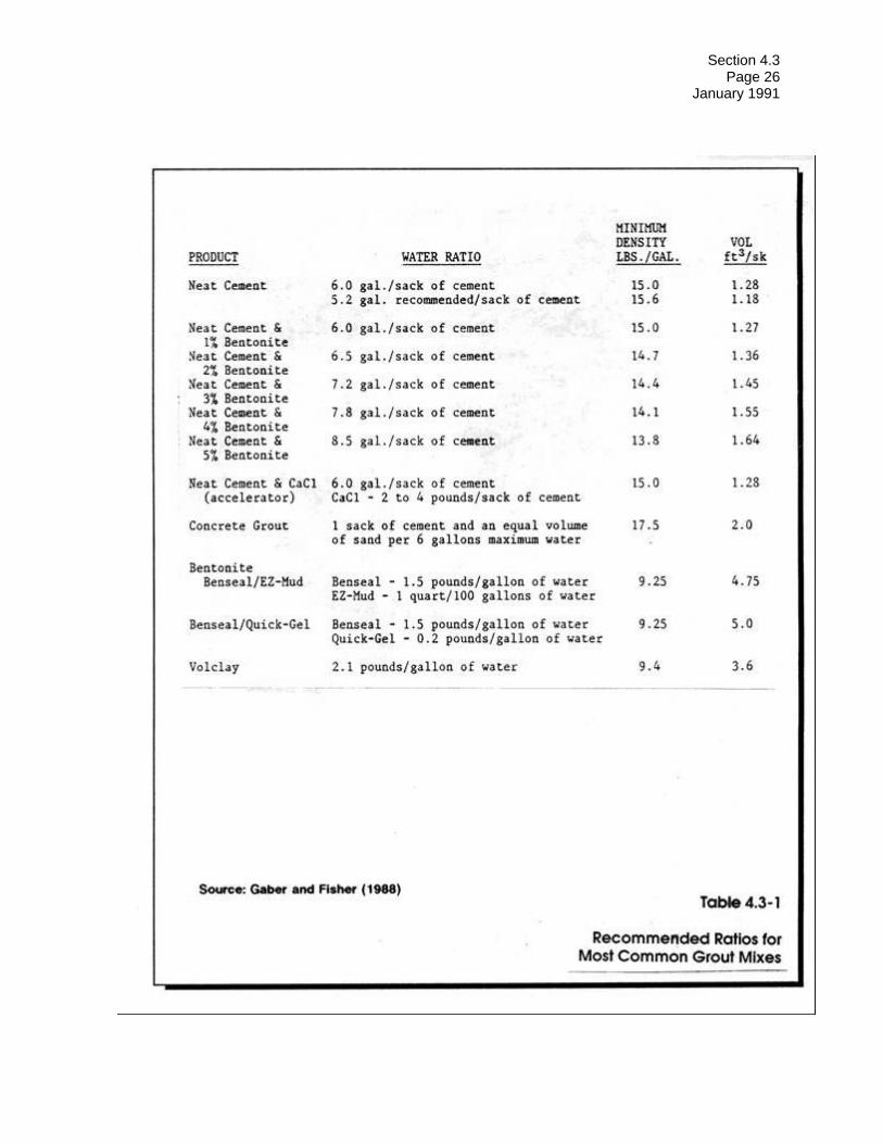
Section 4.3 Page 26
January 1991

COMMONWEALTH OF MASSACHUSETTS
DEPARTMENT OF ENVIRONMENTAL PROTECTION
STANDARD REFERENCES FOR MONITORING WELLS
SECTION 4.4 AS-BUILT NOTES AND RECORDS

Section 4.4 Page i
January 1991
SECTION 4.4 AS-BUILT NOTES AND RECORDS
TABLE OF CONTENTS
Section Title Page No. 4.4-1 PURPOSE ............................................................................................... 1 4.4-2 METHODOLOGY .................................................................................... 1 4.4-3 EXAMPLES OF EXISTING AND PROPOSED WATER WELL COMPLETION FORMS............................................................................ 2 4.4-3.1 Well Completion Report Required by the Water Resources Commission............................................................................ 2 4.4-3.2 Well Completion Report for Well Owner and Local
Board of Health, Proposed by Division of Water Supply, Department of Environmental Protection ..................................... 3
4.4-3.3 Water Quality Report, Proposed by DEP Division of Water Supply........................................................................... 4

Section 4.4 Page ii
January 1991
LIST OF FIGURES Figure Title Page No. 4.4-1 Water Well Completion Report Available from
Department of Environmental Management, Division of Water Resources................................................................................. .7
4.4-2 Example of an As-built Overburden Monitoring Well Form................................................................................. 8 4.4-3 Example of an As-built Bedrock Monitoring Well Form ................................................................................................. 9
APPENDICES Appendix Title Page No. A Checklist and As-built Form for Monitoring Well Installation.................... 11 B Review of Requirements for Registration and Well Completion Reports; Department of Environmental Management ............................. 17

Section 4.4 Page 1
January 1991
4.4 AS-BUILT NOTES AND RECORDS 4.4-1 PURPOSE The purpose of an As-built Record is to compile permanent information about the actual location and construction of a specific monitoring well, including the subsurface geology at the well location. There are several reasons for submitting such information:
o To ensure that the minimum construction standards have been met, and that the installation is suitable for the site conditions.
o To provide an historical database of information on existing monitoring wells,
subsurface materials, and water quality.
o To enable others to assess the integrity of the well installation so as to be able to evaluate the validity of the environmental data obtained from the well.
o To enlarge the database available from the centralized repository maintained by
Water Resources Division of the Department of Environmental Management (WRD/DEM).
o To meet the requirements for well drillers by Massachusetts General Law
Chapter 21 Section 16 and The Department of Environmental Management regulations 313 CMR 3.01(5).
4.4-2 METHODOLOGY Ideally, the methodology used to achieve the purposes described above should provide a standardized format for evaluating monitoring well installations and for compiling the relevant information on a computerized database. It is possible to provide such information in either narrative or graphic format, or both. There are two key state agencies, the Department of Environmental Management (DEM) and the DEP, who are responsible for collecting such information. The DEM regulates the drilling of wells and currently requires that well completion reports (including water and monitoring wells) be signed and submitted to DEM by a Massachusetts registered well driller (Figure 4.4-1). The person doing the actual drilling does not have to be registered. However, they must be supervised by a Massachusetts-registered driller. The DEP regulates the installation of monitoring wells for protecting public water supply wells (Bureau of Resource Protection) and for waste site investigations and various permits (Bureau of Waste Site Clean Up and Bureau of Waste Prevention.)

Section 4.4 Page 2
January 1991
The well completion reports required by the DEM for water wells is not sufficient for technical review of monitoring wells. For this reason the DEP has developed an As-built Form (Appendix A) and a boring log format (see Section 3.2) specific to monitoring wells. The information contained within them is considered essential for DEP technical review. Use of the formats is strongly recommended. However, they may be modified to fit specific needs. As-built and boring logs may be combined to provide graphic illustration of the well construction along side the boring log information. Include copies of as-built and boring log formats in the proposed work plan (Section 2.0). Appendix A also serves as an informational checklist for monitoring well installations. A schematic drawing of the installed well frequently serves to provide much of the same information that has been requested in narrative form. Examples of schematic drawings of As-built monitoring well forms are included as Figures 4.4-2 and 4.4-3. 4.4-3 EXAMPLES OF EXISTING AND PROPOSED WATER WELL COMPLETION FORMS 4.4-3.1 Well Completion Report Required by the Water Resources Commission State Regulation 313 CMR 3.00 states, in part, that "Well drillers' reports will be submitted to the Water Resources Commission, Division of Water Resources, within thirty days of completion of any water well." 313 CMR 3.00 further states that: "Within thirty days after completion of any water well (productive or non-
productive*), a registered well driller shall submit to the Water Resources Commission, Division of Water Resources, a report containing:
(1) the name of the owner of the well; (2) the geographic location of the well (this shall be given accurately to enable
easy plotting on a U.S. Geological Survey Topographic [1:25,000 scale] map); (3) well depth; (4) depth to bedrock or refusal; (5) casing type; (6) casing size and casing length;

Section 4.4 Page 3
January 1991
(7) well screen type; (8) well screen length; (9) well screen depth set; (10) static water level; (11) method used to test well yield; (12) length of time (in hours) that the well was pumped;
* "Non-productive Well" is defined in 313 CMR 3.00 as: A well which has been dug or drilled and sufficient water for its intended use is not available, or a well which has been dug or drilled for monitoring purposes.
(13) drawdown; (14) well yield; and (15) drilling logs describing the material and thickness penetrated.
Report forms will be issued by the Regulating Agency upon request." A copy of the current DEM Water Well Completion Report is included in Figure 4.4-1. Their policy on monitoring wells is included in Appendix B. 4.4-3.2 Well Completion Report for Well Owner and Local Board of Health,
Proposed by Division of Water Supply, DEP
In addition to the information required on the "Water Well Completion Report" form discussed above, it is recommended by DEP's Division of Water Supply that the following information be submitted to the well owner and, if required, the local Board of Health:
(1) The reference point for all depth measurements. (2) The depth at which the first water was encountered. (3) The composition and thickness of each stratum (clay, silt, sand and gravel, cemented formations, hard rock formations, etc.). Particle size, range and shape, along with rock type and smoothness, should be included. See Section 3.5, Soil Classification. Descriptions of materials should be made using the Udden-Wentworth scale or the USDA and Soil Sci. Soc. Amer. Scale. If another type of classification system is used, then this scale should be submitted with the report. Also, a Rock Quality Designation should be done in order to determine the fracturing extent of the bedrock if the private well is located in bedrock. See Section 3.7, Rock Classification.

Section 4.4 Page 4
January 1991
(4) The depth interval from which each water and formation sample was taken. (5) The depth at which the borehole diameter changes, if applicable. (6) Any changes in Static Water Level with well depth. (7) The number of feet drilled. (8) The number of hours on the job. (9) Any shutdowns that occurred due to equipment failure. (10) Water level in the well at the beginning and end of each shift. In rotary
drilling, the fluid level in the hole should be measured daily prior to starting pumps.
(11) Water level at each change of formation if readily measurable with the drilling method used. (12) Any and all other pertinent information for a complete and accurate log (i.e.,
temperature, pH, and appearance [color] of any water samples taken). (13) Depth or location of any lost drilling fluid, drilling materials, or tools. (14) The depth of the surface or sanitary seal, if applicable. (15) Total depth of completed well. (16) The nominal hole diameter of the well bore above and below casing seal. (17) The quantity of cement (i.e., number of sacks) installed for the seal, if applicable. (18) The depth and description of the well casing. (19) The description (to include length, diameter, slot sizes, materials, and
manufacturer) and location of well screens, or number, size, and location of perforations.
(20) The sealing off of water-bearing strata, if any, and the exact location thereof. (21) Records of well alignment and plumbness. (22) Rate of Penetration Log: The rate of penetration into the formation should be
recorded when drilling the hole. Types of bits used in addition to various weights applied on these bits, throughout the hole, should be submitted in this log. Any other information in regard to penetration rates should also be included."

Section 4.4 Page 5
January 1991
4.4-3.3 Water Quality Report, Proposed by DEP's Division of Water Supply It is recommended by DEP's Division of Water Supply that the local Board of Health require the well owner to submit to the Board a Water Quality Report any time a private water supply is tested. The report should include:
(1) who performed the sampling (i.e., the well owner, well owner's representative, BOH member, lab personnel);
(2) where in the system the sample was obtained (point-of-use or point-of-
entry) and, if sampled at the point-of-use, whether or not the system was flushed prior to sampling;
(3) type of water treatment used (chemical or special device, if
applicable); (4) the time and date of sampling, of delivery to the laboratory, of extraction
(or holding time - whichever is appropriate), and of sample analysis; and, (5) a copy of the laboratory's test results.
Results that indicate no contamination are as important as those that indicate water quality problems because these results provide background data in case of future contamination. A complete record of all testing results is also useful when designing local water quality testing programs. In these Standard References, this subject is more fully discussed in Section 6.0 Sampling and Analysis of Ground Water Samples.

Section 4.4 Page 6
January 1991
LIST OF FIGURES Figure Title Page No. 4.4-1 Water Well Completion Report Available from
Department of Environmental Management, Division of Water Resources ................................................................... .7
4.4-2 Example of an As-built Overburden Monitoring Well Form ................................................................................................ .8 4.4-3 Example of an As-built Bedrock Monitoring Well Form ................................................................................................. 9

Section 4.4 Page 7
January 1991

Section 4.4 Page 8
January 1991

Section 4.4 Page 9
January 1991

Section 4.4 Page 10
January 1991
APPENDICES Appendix Title Page No. A Checklist for Monitoring Well Installation and
As-Built Form ......................................................................................... 11 B Review of Requirements for Registration and
Well Completion Reports; Department of Environmental Management................................................................... 17

Section 4.4 Page 11
January 1991
APPENDIX A
A CHECKLIST FOR MONITORING WELL INSTALLATION AND
AS-BUILT FORM

Section 4.4 Page 12
January 1991
APPENDIX A
A CHECK LIST AND AS-BUILT FORM FOR MONITORING WELL INSTALLATION
1. Monitoring Well I.D. Number I.D. Number ______________________________________________________ 2. Property Owner
Name: Address: ___________________________________________________ __________________________________________________________ __________________________________________________________
Telephone No.: ______________________________________________ Contact ____________________________________________________
3. Individuals Involved in Installation
Name of Drilling Contractor Firm: _____________________________________________
Address: _________________________________________________________ __________________________________________________________ Name of Driller: ___________________________________________________
Name of Consultant Firm: _____________________________________________ Address: ___________________________________________________ ____________________________________________________ Name of Inspector ___________________________________________

Section 4.4 Page 13
January 1991
4. Date Installed Date: 5. Location
Town: Plot Plan Number:____________________________________________ NOTE: A copy of the plot plan map showing the well locations and well ID numbers must be submitted with this form. Name of Surveyor: ___________________________________________ Address: ___________________________________________________
___ _________________________________________________
C.E. Reg. No.:___________ or RLS Reg. No. ___________________ Coordinates (check one): Latitude and Longitude _________ UTM Grid ___________________ N-S line: E-W line:
6. Elevation
NOTE: All elevations must be provided as feet above Mean Sea Level (MSL) Reference Datum:____________________________________________ Vertical Accuracy:____________________________________________ Elevation, Top of Riser, uncapped ____________________________ feet Elevation, Ground Surface:__________________________________ feet Name of Surveyor: ___________________________________________ Address: ___________________________________________________ ______________________________________________________ ____

Section 4.4 Page 14
January 1991
C.E. Reg. No.:__________ or RLS Reg. No.: ______________________ 7. Drilling Information
Drilling Method:______________________________________________ _ Borehole Diameter:______________________________________inches Water source used:___________________________________________ Water quality tested: yes___________ no _____________________ Criteria for refusal: _________________________number of blow counts
8. Geology
(a) Soil
Sampling interval:_______________________________ (b) Rock
Depth to top of rock: feet below ground surface
(c) Aquifer Tests
Type _
Hydraulic conductivity ___________________________________
Method of Analysis _____________________________________
9. Well Installation Details
Single-level well________ or Multi-level well _____________ NOTE: Complete sections (a) through (e) for each separate monitoring
zone in multi-level well installations. (a) Riser pipe
I.D. __________inches

Section 4.4 Page 15
January 1991
Material Stickup Length ___________________________________________ feet or Stickdown Length_ ________________________________________ feet Total Length of Riser Pipe __________________________________ feet
(b) Well screen I.D. ___________inches Length_ feet Screen Type ________________________________________________ Slot Size ___________________________________________________ Sediment Trap yes _________ no __________ if "yes," how long is the sediment trap? ____________________ inches
(c) Filter pack
Quantity ___________________________________________ cubic feet Material Description __________________________________________ __________________________________________________________
(d) Divider seal Bentonite pellets placed above the filter pack? yes__________ no____________ Depth of seal below land surface: From _______ to ________ feet Method of placement _________________________________________ __________________________________________________________
(e) Annular seal Type of grout slurry used ______________________________________

Section 4.4 Page 16
January 1991
Mix ratio Method of Placement_ ________________________________________ Volume______________gallons Depth below Land Surface: From ____ to ____feet (f) Surface seal Type: Mix ratio: Depth below Land Surface: From _____ to ____ feet Apron: Diameter:__________________________feet Thickness:_______________________inches Protective casing yes ___________ no __________ or Road box yes ___________ no __________ Material: ___________________________________________________ Length: _________________________________________________ feet I.D.: __________________________________________________inches
10. Well Development
Method:________________________________________________ Amount removed: ______ gallons or duration ______ hours Quality of water after development_______________________________
11. Signature Block
Prepared by:__________________________ Date ________________ (Driller or Inspector) Submitted by:__________________________ Date ________________ (Consultant) Property Owner:________________________ Date ________________

Section 4.4 Page 17
January 1991
APPENDIX B
REVIEW OF REQUIREMENTS FOR REGISTRATION AND WELL COMPLETION REPORTS; DEPARTMENT
OF ENVIRONMENTAL MANAGEMENT

Section 4.4 Page 18
January 1991

Section 4.4 Page 19
January 1991

Section 4.4 Page 20
January 1991

COMMONWEALTH OF MASSACHUSETTS
DEPARTMENT OF ENVIRONMENTAL PROTECTION
STANDARD REFERENCES FOR MONITORING WELLS
SECTION 4.5 WELL DEVELOPMENT

Section 4.5
Page i January 1991
SECTION 4.5 WELL DEVELOPMENT
TABLE OF CONTENTS
Section Title Page No. 4.5-1 PURPOSE ................................................................................................ 1 4.5-2 METHODOLOGY ..................................................................................... 2 4.5-2.1 Over-pumping .......................................................................................... 3 4.5-2.1.1 Advantages and Disadvantages .............................................................. 3
(a) Advantages......................................................................................... 3 (b) Disadvantages ................................................................................... 3
4.5-2.2 Backwashing (Rawhiding). ........................................................................ 4 4.5-2.2.1 Advantages and Disadvantages .............................................................. 4
(a) Advantages........................................................................................ .4 (b) Disadvantages ..................................................................................... 5
4.5-2.3 Mechanical Surging ................................................................................. 5 4.5-2.3.1 Advantages and Disadvantages .............................................................. 5 (a) Advantages ........................................................................................ .5 (b) Disadvantages ................................................................................... .6 4.5-2.4 Air-Surging and Air-lift Pumping .............................................................. 6 4.5-2.4.1 Air-Surging................................................................................................ 6 4.5-2.4.2 Air-lift Pumping ........................................................................................ 6 (a) Advantages and Disadvantages......................................................... .7 (1) Advantages ....................................................................................... 7 (2) Disadvantages.................................................................................... 7 4.5-2.5 Water Jetting............................................................................................. 8 4.5-2.5.1 Advantages and Disadvantages .............................................................. 8 (a) Advantages .......................................................................................... 8 (b) Disadvantages ................................................................................... .8
REFERENCES ............................................................................................................... 9
Section 4.5 Page ii
January 1991
LIST OF FIGURES Figure Title Page No. 4.5-1 Operation of Surge Block System........................................................... 11 4.5-2 Detail of Surge Block Equipment ............................................................ 11 4.5-3 Air-lift Development System With Check Valve ...................................... 12

Section 4.5 Page 1
January 1991
4.5 WELL DEVELOPMENT 4.5-1 PURPOSE Well development is a necessary step in the completion of most ground water monitoring well installations. Development of a monitoring well helps to remove sediment and enhance the hydraulic connection between the well and the aquifer. Regardless of the drilling method used in the installation of a monitoring well, all methods cause some alteration or rearrangement of the fill or natural soil or rock material in which the well screen is placed. Since monitoring wells are installed to collect physical and chemical data indicative of in-situ aquifer conditions, the methods of drilling and installing wells should minimize the disturbance of aquifer materials that adversely impact the quality of the data collected. Wells not intended for sampling, such as piezometers and observation wells, may not require development. The objective of well development is to enhance the hydraulic connection between the well screen and the natural formation or fill by removing fine soil material or drill cuttings and subsequently rearranging the natural or artificial sand filter pack around the well. Well development may increase the hydraulic conductivity in the vicinity of the well screen. This should be considered when in-situ hydraulic conductivity tests are planned. Appropriate mechanical rearrangement of the sand or gravel pack (i.e., development) will allow the ground water to move through the sand pack more easily and reduce the amount of fines that enter the well. Since ground water in most New England aquifers travels at velocities too low to retain suspended material, any turbidity associated with monitoring wells is likely to be an artifact of the well installation process. Well development can reduce this turbidity and, therefore, reduce the chance of chemical alteration of ground water samples caused by suspended sediments. In addition, it can remove fluids introduced during drilling or installation. In this discussion, well development involves preparation of the well for collection of hydrologic and chemical data. If samples are collected for chemical analysis, the well must be purged prior to sample collection (see Section 6.0). Frequently, inadequate consideration is given to the selection of appropriate well development techniques and duration of development, compared with the time spent on selection of well materials or sampling protocols. In order to obtain hydrologic and chemical data that is representative of the pre-drilling site, the hydrologic conditions in the vicinity of the well screen should be restored to their natural state as much as possi-ble. Additionally, consideration must be given to the amount of drilling water or fluid that was introduced into the aquifer during drilling. If ground water flow velocities are low it may be desirable to remove the added drilling water in order to obtain representative samples for chemical analysis. Care should be taken during well development to avoid entrapping air in the formation or plugging well screens with fines. If additional clean water is introduced during development, care should be taken to make certain that the amount of water removed exceeds the amount that has been added.

Section 4.5 Page 2
January 1991
The use of development methods that introduce additional water into the formation or that cause significant alteration of the natural materials in the vicinity of the screen may be undesirable for some ground water monitoring applications, such as highly contaminated aquifers. If additional water is introduced during development to flush the screen, this volume of water must be removed as part of the development process and may require storage and disposal as a hazardous waste. In choosing a well development method, the purpose of the well must be considered. Wells used primarily for potentiometric head information can be developed by the introduction of clean water, since the addition of water will not jeopardize the validity of water level data. However, if the primary purpose of the monitoring well is to provide data on groundwater chemistry, the effects of the development method on the contaminants and natural geochemistry must be considered. The purposes of well development are:
o to remove fluids introduced during drilling or installation.
o to reduce the amount of fine grained material entering the well from the surrounding formation
The following section on development methodology will specifically address the development techniques most widely used for monitoring wells. There are other techniques that are used for development of water supply wells, but they may not be applicable for developing monitoring wells. The methods described are not necessarily appropriate for all monitoring wells. Aquifer conditions and constraints, especially permeability and depth to the water table, will dictate the specific applicability of any of these methods. It is expected that variations and combinations of these methods will probably be required at some sites. It should be noted that all equipment placed in a monitoring well for development, purging or sampling should be decontaminated. Decontamination methods are presented in sections 6.5 and 3.3 of the Standard Reference Document. 4.5-2 METHODOLOGY Well development can be performed using a variety of methods and equipment. The specific method chosen for development of any given well is governed by the purpose of the well, well diameter and material, depth, accessibility, geologic conditions, static water level in the well, and the type of contaminants present, if any. Any of the development methods discussed in this section can result in overdevelopment. Monitoring wells should be developed only to the point that enables them to function for their intended purpose. The most technically feasible and commonly used methods for developing monitoring wells include:
o Over-pumping o Backwashing (or rawhiding) o Mechanical surging o Air-lift pumping o Water jetting

Section 4.5 Page 3
January 1991
Bailing is a technique that is not generally recommended for well development, because it is slow and not effective in adequately removing suspended sediment. Bailing is generally used for ground water sampling and sometimes for purging wells prior to sampling. 4.5-2.1 Over-pumping Over-pumping a well involves pumping at a faster rate than the well would normally be pumped or purged for sample collection. This is one of the easiest and most common methods of well development. Theoretically, overpumping increases the hydraulic gradient near the well by drawing the water level down to as low a level as possible. The steepened hydraulic gradient increases the velocity of the ground water moving through the screen into the well. The increased velocity will move residual fine soil or rock particles into the well and clear the well screen of this material. Care must be taken not to entrap air into the formation around the screen during development. This can be prevented by not lowering the water level outside the well below the bentonite/cement seal. This method of over-pumping is best suited to aquifers comprised of sands and gravels or high-yielding consolidated rock with shallow water tables. The suction line, pump, or bailer is lowered into the well and water is removed. If the permeability of the formation is sufficiently high, repositioning of the pump or line intake within the screen may be re-quired to pull material into the well along the entire length of the screen. Typical problems encountered using this method are the lack of effective pumping devices that will fit within a 2-inch diameter monitoring well and produce satisfactory pumping rates. Above-ground peristaltic/centrifugal pumps are effective when the water level is within 15 to 20 feet of the ground surface. If the ground water contains hazardous constituents, pumping large volumes of contaminated water may pose disposal problems. 4.5-2.1.1 Advantages and Disadvantages (a) Advantages
o Useful in wells with shallow water-levels (less than 25 feet deep) where a suction line can be used.
o Relatively simple procedure.
o Most drill rigs will have the capability of pumping at a high rate at depths
of 10 to 15 feet or less. (b) Disadvantages

Section 4.5 Page 4
January 1991
o If the permeability is quite high or quite variable, only a section of the screened zone may actually be developed, especially in wells with long screens.
o Over-pumping may compact finer sediments around borehole and screen,
restricting groundwater flow into the screen If this happens it may be very difficult to correct.
o May result in an unstable formation around the well screen (i.e., bridging
of fines may allow formation of voids around coarser-grained material).
o At contaminated sites over-pumping may produce a large volume of contaminated discharge water that must be disposed of as a hazardous waste.
4.5-2.2 Backwashing (Rawhiding) Unfortunately, overpumping alone may not adequately develop most monitoring wells. Pulling water toward the screen without some return of water into the formation may result in bridging of the soil or rock particles around the screen. This bridging may continue until the pumping is stopped. Once pumping has stopped, the flow may reverse and unseat the bridged particles. The fines may re-enter and settle into the well until the next time it is pumped. A modification to the over-pumping technique that increases the effectiveness of development is called surging and pumping, rawhiding or backwashing. In this method a pump is used to lower the water level in the well, thereby increasing the ground water velocity entering the screen. However, after drawdown is achieved, the pump is turned off and the water in the pump discharge line is allowed to re-enter the well. This reversal of flow through the screen will help prevent bridging and reduce the suspended fines that may re-enter the well screen. The equipment used for this method is the same as in over-pumping with similar operational techniques. A problem with this method is that it tends to develop the most permeable zones within the screened portion of the well. This method should be used with caution in wells intended for sampling because it introduces and recycles water into the formation. In order to ensure that representative water samples are collected, more water should be withdrawn from the formation than is introduced. Surging and pumping may be the most appropriate technique if short well screens (e.g., 5-foot or less) are installed in relatively homogeneous aquifer materials. Because the geology is relatively uniform, this technique will develop the entire monitored zone.
Section 4.5 Page 5
January 1991
4.5-2.2.1 Advantages and Disadvantages (a) Advantages
o Will help reduce bridging of fines around the well screen.
o Effective for short screens (5-foot or less) located in homogenous
aquifers.
(b) Disadvantages
o May overdevelop the more permeable zones, leaving a portion of the well undeveloped.
o If the screened zone is highly contaminated, backwashing may cause
mixing of the contaminants. 4.5-2.3 Mechanical Surging Another method occasionally used to develop monitoring wells is surging. This technique employs a tool called a surge block, commonly found on a cable tool rig. This device first forces water within the well through the well screen and out into the formation, and then pulls water back through the screen into the well along with fine soil or rock particles. Surge blocks are usually fabricated for specific well applications. A typical surge block construction detail and application is shown in Figures 4.5-1 and 4.5-2. The surge block is typically attached to a drill rod, drill stem, or line that has sufficient weight to allow the surge block to rapidly drop through the water column. The surging action should start at a slow pace, near the water level within the well and progress to a faster pace near the well screen. Surging action can be carried out within the well screen if adequate measures are taken to clean out accumulated silt or material prior to surging. Otherwise, the fines may be forced out through the well screen into the surrounding filter pack. Accumulated material may also bind or lock the surge block in place if precleaning is not performed. Periodic bailing or pumping of the soil or rock particles is necessary regardless of the location of the surging within the well. A typical surge block has approximately 1/4-inch clearance between the flexible leather or rubber discs and the inside of the well casing. Violent or too rapid surging in a well situated in a low permeability formation may damage the well. Variations in surge block construction involve the addition of flap valves to allow some water and silts to pass through the block rather than between the block and wall of the well. Additionally, check valves can be added to the surge block to allow removal of development water and associated silts. After surging, additional development can be performed, if desired, using the rawhiding or backflushing techniques previously described.

Section 4.5 Page 6
January 1991
4.5-2.3.1 Advantages and Disadvantages (a) Advantages
o Gentle surging combined with gentle pumping through the center of the surge block has been very successful for development in formations containing a considerable amount of fine material.
o Inexpensive and relatively simple tool.
o Effective in wells installed in highly permeable homogenous formations. o Does not require the addition or withdrawal of substantial volumes of
discharge water except for flushing. (b) Disadvantages
o Vigorous surging may damage non-metallic well screens.
o May cause the formation around the screen to become clogged by pushing fines back into the formation, reducing flow into the well.
o If the surge block fits too tightly into the well casing, the surge block can
damage the well screen.
o May remove sufficient formation material outside and above the well screen causing the seal to collapse, resulting in infiltration of overlying aquifer material.
4.5-2.4 Air-surging and Air-lift Pumping Air development involves the use of air pressure to remove water from a well. Two basic techniques are air-surging and air-lift pumping. 4.5-2.4.1 Air-surging Although air-surging is described, it is not recommended for monitoring well development. In air-surging development, compressed air is blown into the well to force water and soil or rock particles out of the well under pressure. This technique removes soil or rock accumulations from a well but has the potential to trap air in the formation pore spaces or fractures. If air is entrapped it may inhibit the flow of ground water into the well.

Section 4.5 Page 7
January 1991
4.5-2.4.2 Air-lift Pumping Air-lift pumping is similar to air-surging but this technique does not allow air to pass through the well screen. With this technique compressed air is introduced into the well through a small tube in the base of an eductor pipe that has been lowered to the base of the well. The air displaces the water in the eductor tube, causing the water to flow into the eductor tube and be discharged at the surface. For development by this method to be successful, it is necessary to have a ratio of submergence of at least 60 percent. That is, the water must rise high enough in the well so that it is possible to have 60 percent of the airline and eductor hose in the well under water. The distance the line is under water should be divided by the total length of line in the well, and then multiplied by 100. This will yield the percentage of submergence. For example, if a 170-foot airline is under water 110 feet, the submergence is calculated as follows: 110 x 100 = 0.647 x 100 = 64.7% 170 A typical air-lift system consists of two small-diameter tubes: one is a small tube attached to an air compressor and the other larger tube acts as the water discharge. The air tube is attached to the eductor tube and terminates inside and facing upward within the eductor tube (see Figure 4.5-3). Portable air compressors with a range from 40 to 100 psi at 5 to 15 cfm are typically used for well development. If possible, an oil-less compressor should be used; otherwise a hydrocarbon filter should be attached to the discharge line on the air compressor to filter out any airborne oils produced by the compressor. Compressed air is slowly added to the system until water and silt flow out of the discharge tube. Use of nitrogen gas, rather than compressed air, may be desirable because accidental introduction of nitrogen gas into the well is less likely to affect the water quality than the compressed air. This development method is similar in function to the over-pumping technique discussed in Section 4.5-2.1. The advantage of the air-lift system is that wells with very deep static water levels or wells installed in silty aquifer materials can be easily developed. This system can be built to fit within a 2-inch diameter well; it is easily installed and operated. However, air-lift pumping without backflushing still creates the potential for bridging around the screen. A combination of air-lift pumping with backflushing should result in effective development of most monitoring wells. This method can be conveniently performed by first pumping and then shutting off the air to allow the rising water column to fall back down the discharge pipe. As with any development system, extreme care should be taken not to introduce air or highly aerated water into the formation as this may alter the water quality, permeability and geochemistry in the vicinity of the well.

Section 4.5 Page 8
January 1991
(a) Advantages and Disadvantages (1) Advantages
o Effective in wells with deep static water levels and in wells containing a lot of clays and silts
o Effective in small diameter wells.
o Capability to pump and surge without removing the equipment.
o A drill rig is not required for this method.
o Can control pumping rate by controlling air-flow.
(2) Disadvantages
o May force air into the formation, which may lead to air locking of the formation, affecting permeability, water quality and the flow of water to the well.
o Generally, only low flow rates (e.g., 1 to 2 gpm) are possible.
o May not be effective in wells with less than 30- or 40-feet of standing water.
4.5-2.5 Water Jetting High velocity water jetting is a rarely used but effective technique for development of wells installed in highly permeable aquifers. Jetting consists of the discharge around the well screen of horizontal jets of water under high pressure. The water jets act to dislodge soil or rock particles near the well screen and break up any dense soil or filter cake caused by mud rotary or auger drilling. Both auguring and mud rotary drilling methods tend to develop a filter cake or dense soil or rock layer on the borehole wall. Unless removed, this layer can alter the natural permeability of the aquifer. In order to be effective in developing the well, water jetting must be accompanied by pumping or air-lifting to remove the fines. Again, this development method should be used with caution to avoid damaging the screen or developing voids in the filter pack surrounding the screen. 4.5-2.5.1 Advantages and Disadvantages (a) Advantages
o Effective in highly stratified, unconsolidated formations. o Can be accomplished with most drill rigs. o Entire section of screened zoned can be developed.
(b) Disadvantages

Section 4.5 Page 9
January 1991
o Introduces water into the formation. o Requires equipment that may not fit into a 2-inch diameter well. o More time-consuming than other methods.

Section 4.5 Page 10
January 1991
REFERENCES Driscoll, F.G., 1986, Groundwater and wells: St. Paul, MN, Johnson Division, UOP, Inc.,
1089p.

Section 4.5 Page 11
January 1991
SECTION 4.5 WELL DEVELOPMENT
LIST OF FIGURES
Figure Title Page No. 4.5-1 Operation of Surge Block System........................................................... 11 4.5-2 Detail of Surge Block Equipment ............................................................ 11 4.5-3 Air-lift Development System With Check ................................................. 12

Section 4.5 Page 12
January 1991

Section 4.5 Page 13
January 1991

COMMONWEALTH OF MASSACHUSETTS
DEPARTMENT OF ENVIRONMENTAL PROTECTION
STANDARD REFERENCES FOR MONITORING WELLS
SECTION 4.6 DECOMMISSIONING OF MONITORING WELLS

Section 4.6 Page i
January 1991 SECTION 4.6
DECOMMISSIONING OF MONITORING WELLS
TABLE OF CONTENTS
Section Title Page No.
4.6-1 PURPOSE ................................................................................................. 1 4.6-2 PRELIMINARY WORK TO BE PERFORMED BEFORE UNDERTAKING WELL PLUGGING.......................................................... 2 4.6-2.1 Who can Perform Proper Well Decommissioning? .................................. .2 4.6-2.2 Location and Inspection............................................................................. 2 4.6-2.3 Clearing the Well ....................................................................................... 3 4.6-2.4 Casing Removal or Destruction ................................................................. 3 4.6-3 PLUGGING THE WELL............................................................................ .4 4.6-3.1 Grouting Material ...................................................................................... .4 4.6-3.2 Grout Placement...................................................................................... .5 4.6-3.3 Calculations and Measurements ............................................................. .6 4.6-4 FINAL SURFACE FINISH ....................................................................... 6 4.6-5 RECORD OF DECOMMISSIONING. ...................................................... .6 4.6-6 PROHIBITIONS ........................................................................................ 7

Section 4.6 Page ii
January 1991
LIST OF FIGURES
Figure Title Page No. 4.6-1 Diagram of an Abandoned Overburden Well............................................ .9 4.6-2 Diagram of an Abandoned Well Screened in Bedrock .................................................................................................. 10 4.6.3 Diagram of an Abandoned Well (Open Hole Well in Bedrock) ............................................................................................. 11 4.6-4 Minnesota Abandoned Well Report ......................................................... 12 4.6-5 Iowa Abandoned Water Well Plugging Record ...................................... 13

Section 4.6 Page 1
January 1991
4.6 DECOMMISSIONING OF MONITORING WELLS 4.6-1 PURPOSE Any abandoned monitoring well that is no longer in use or that is unfit for its intended purposes should be decommissioned. Plugging the well and surface restoration are the central features of the decommissioning process. Plugging consists of constructing a low permeability cylinder or plug within that portion of the subsurface occupied by the well and its annulus, including the uncased portion of bedrock wells as well as the cased portion. Surface restoration consists of the removal of the upper three to four feet of the well and backfilling the area with an effective seal. An abandoned monitoring well has been defined for the purpose of these Standard References (SRs) as "a well whose use has been permanently discontinued; as used in these References it includes a monitor-ing well, piezometer, or observation well that is no longer suitable for use either for water-level measurements or water quality sampling." Proper plugging of such wells will:
o Eliminate physical hazards
o Prevent ground water contamination
o Conserve the yield and hydrostatic head of confined aquifers
o Prevent the intermingling of potable and non-potable ground water, and
o Prevent the migration of contamination through a confining layer separating aquifers.
It should be noted that the objective in Massachusetts differs markedly from the goals established by the American Water Works Association and the statutes, regulations, or guidelines of most other states. Many documents contain the following language: "The basic concept of proper sealing of abandoned wells is restoration, as far as feasible, of the controlling hydrogeological conditions that existed before the well was drilled and constructed. If this restoration can be accomplished, all the objectives of plugging wells will be adequately fulfilled." To accomplish this goal some states have suggested the placement of sand and gravel opposite the more permeable subsurface zones and clay opposite less permeable zones. While that goal is an admirable one, it is also one which, in DEP's opinion, is unattainable in practice. In order to meet the objectives of proper plugging as stated above, DEP has tried to develop a simple, workable approach that will solve the existing and potential problems from unsafe abandoned wells.

Section 4.6 Page 2
January 1991
Some examples of the types of unsafe wells that may cause problems include:
o Buried uncapped wells: contaminants may enter the well through the buried top of the casing, travel down the well casing, and enter the aquifer through the well screen and wall of the annulus;
o Wells with cracked or corroded casing: surface water may enter the well;
o Improperly constructed wells: an unsealed or improperly sealed annular space
around the outside of a well casing or between an inner and outer casing may serve as a channel for surface water to migrate into an aquifer and/or ground water may be transferred from one aquifer to another;
o Open hole wells in bedrock: may serve to interconnect aquifers in different
formations;
o Unplugged abandoned flowing artesian wells: this can result in a loss of water, reduction of regional artesian head and localized surface flooding; and
o Uncovered and unplugged abandoned wells with large inside diameter: these
may represent a physical hazard to human beings and animals, as well as a disposal receptacle for contaminants, waste, and debris.
4.6-2 PRELIMINARY WORK TO BE PERFORMED BEFORE UNDERTAKING WELL PLUGGING 4.6-2.1 Who Can Perform Proper Well Decommissioning? One should be a registered well driller in Massachusetts or a person knowledgeable with the installation of wells in order to decommission them. There is no nationally recognized or state-approved examination or certification process for well decommissioning and plugging. However, it is obvious that a well contractor or person who is familiar with well construction and the geologic conditions of the region is preferable to a person who does not routinely perform such work. If the existing well must be "over drilled" then a registered Massachusetts well driller must perform the work. It is expected that an experienced well contractor will be familiar with the correct procedures to follow. That experience should provide substantial savings to the property owner in the long run. The property owner should ask the well contractor about his qualifications. Some drillers or contractors specialize in rock wells; others in overburden wells. Some have worked extensively with multi-level wells at sites with contaminated ground water; others have only worked with single-level, cased water wells.

Section 4.6 Page 3
January 1991
4.6-2.2 Location and Inspection Locating the abandoned well is the first step in decommissioning. While some wells are easily located, others may be buried or otherwise concealed. It may be possible to find the location of abandoned wells through contact with past land owners, occupants, retired workers, neighbors, or well contractors. Regulatory officials and hydrogeologic reports may have useful information. The well records maintained by the United States Geological Survey (USGS), Water Supply Division, Massachusetts Section, with headquarters in Marlborough, Massachusetts, all have been assigned coordinates of latitude and longitude. For well locations, historic documents may be used, such as aerial photo and assessing maps, insurance company maps or photographs. Metal detectors may be of value in locating buried metal casings. Obtaining accurate information on the well's original construction and present condition is the next step in decommissioning. This information is best obtained from monitoring well drilling records. Recent well records may be obtained from local Boards of Health, the Water Resources Division of the Department of Environmental Management (DEM), USGS Water Resources Division, or DEP. Next a site inspection is necessary to ascertain the condition of the well and to note if the well is accessible, located in a pit or buried, if a dedicated pump is in place, or if the well is currently operating. The inspection should also note if the well has been damaged or obstructed. A downhole TV camera survey can sometimes provide valuable information as it can verify the current well depth, condition, construction, and the presence or absence of well casing in rock wells. 4.6-2.3 Clearing the Well Decommissioning a well starts with removal of any obstructions, such as drop pipes, check valves and pumps, and clearing any obstacles or debris that may have entered the well. When the well is obstructed by pumps or other equipment have been dropped down the well, the debris must be removed or "fished" out before the well can be sealed. A variety of fishing tools are used to remove obstructions. Threaded taps on the end of a drill rod may be run into the hole in an attempt to screw into the top of a pump or drop pipe. Another type of equipment used is an "over shot" (a casing with inner teeth that is run over the obstacle to be removed). Corkscrews and spears also have been used to hook the obstacle for removal. In some instances the driller may chop or grind up the obstacles in an attempt to clear the well. Debris or other materials such as rock, sand, clay, stones, and wood is usually drilled out or washed out of the hole. This technique appears to be suitable for destroying multi-level wells installed within a single borehole.

Section 4.6 Page 4
January 1991
4.6-2.4 Casing Removal or Destruction Assuming the original well did not have an adequate seal in the annular space outside the well casing, in most cases the original well casing should be destroyed in place or pulled out of the ground. However, if the As-Built Notes and Records indicate that the annular space contains an adequate seal, this information should enable the well contractor to design a simpler and less costly decommissioning procedure. The procedure should not require destruction or removal of the entire well casing, but would require adequate perforation of any well screen to allow the grout to penetrate the filter pack. Insert neat cement grout (or its equivalent) into the uncased portion of a bedrock well or into the filter pack around the well screen and fill the riser pipe with the same grout material. Figures 4.6-1 through 4.6-3 show the zones to be plugged through the well riser for three types of well installation where the annular space contains an adequate seal. Terminate the well casing at a minimum of 3 to 4 feet below the land surface or at the water table, which ever is encountered first. Finally, finish off the well at the land surface in a manner as described in Section 4.6-4. Figures 4.6-1 through 4.6-3 also show the zones to be prepared for a new surface finish. This procedure is appropriate for monitoring wells installed under all types of hydrogeologic conditions. In instances where a well has penetrated a confining layer separating aquifers and there is no evidence that the annular space around the casing was adequately sealed during installation, the most conservative approach is to destroy or remove the casing by over drilling. Simply pulling the casing in this situation may result in the collapse of the formation before an adequate seal can be placed across the confining layer. The easiest way to over drill and keep the cutting bit in line with the hole (rather than straying off the hole) would be to spin casing over and around the existing observation well. The observation well will help hold the casing in line with the borehole as opposed to roller-bitting operations where an in-place casing will tend to deflect the cutting bit. Augers would probably also work in lieu of spinning casing, but spinning casing would probably be better as it is less likely to damage the observation well and, therefore, continue down the hole rather than veering off. If, however, vertical contaminant migration across aquifers is not a concern, such as a shallow (15-30 feet) water table well in glacial sands and gravels, a choice may be made to either over drill the well, pull the well casing out of the ground or to plug the well in place. In this case, the presence or absence of annular seal is not a factor. If attempts are made to pull the casing out of the ground and the hole collapses, care must be taken to compact the materials in the hole to avoid future subsidence at the surface. Regardless of which method is chosen, the most important consideration is to seal the well from possible surface infiltration. This is accomplished by plugging the well/boring (Section 4.6-3) and terminating the well 3 to 4 feet below grade then backfilling with concrete or other appropriate seal (Section 4.6-4). If asbestos well casing is encountered or suspected, plugging the well is the only choice. No attempt should be made to destroy or remove this material from the ground as the risk of creating a friable asbestos problem outweighs the potential negative impact from the well.

Section 4.6 Page 5
January 1991
4.6-3 PLUGGING THE WELL Neat cement (or its equivalent) should be inserted into the open portion of the well bore, whether the opening is in bedrock or overburden. As noted above, special care must be exercised if the well penetrates a confined aquifer. The low permeability layer that creates the confined aquifer must be sealed so that there is no chance of leakage between aquifers. If the hydrostatic head is large, this may present an extreme challenge to the well contractors. 4.6-3.1 Grouting Material There are a large number of grouts available that can be used to plug abandoned wells. Each grout has certain special characteristics and distinctive properties. Therefore, one grout may be especially suited for doing a particular job. The selection of the most appropriate material or combination of materials is dependant on the construction of the well, the nature of the formation penetrated, the material and equipment available, the location of the well with respect to sources of contamination, and the cost of doing the work. At the present time, a neat cement grout possesses most of the advantages that DEP looks for in a plug for abandoned wells where the grout will be inserted through the well riser. It may be used as grout for abandoned wells installed in all geologic formations. Neat cement is superior for sealing small openings, for penetrating any annular space outside of casings, and for filling voids in the surrounding formation. When applied under pressure, it is strongly favored for sealing wells under artesian pressure or those encountering more than one aquifer. Neat cement is also superior to other grouts as it avoids the danger of separation. The use of bentonite pellets to plug the saturated portions of a well with a neat cement plug above is an acceptable but, less satisfactory method. The use of bentonite pellets is recommended solely for plugging shallow (15-30 feet) water table wells in highly permeable aquifers where there is no threat of vertical migration of contamination and where bridging is less likely. Care must be taken to compact the bentonite to avoid bridging of the pellets in the casing. See Section 4.2 Specifications for Wells, Screen, Filters, and Seals, for a more thorough treatment of this subject. If the original well was not properly sealed or if there is not sufficient information available to determine whether a well was properly sealed, the most appropriate grout for such purposes appears to be a bentonite/cement grout, such as is recommended in Section 3.9 Plugging Boreholes.

Section 4.6 Page 6
January 1991
4.6-3.2 Grout Placement After clearing of the well bore, the well is ready for sealing. Grout slurries must be placed from the bottom to the top and not from the top to the bottom. In other words, slurries cannot be poured from the land surface into the borehole, annular space, or well to be sealed. When grout is placed at the bottom of the space to be grouted and finally appears at the surface or top, the integrity of the plug is assured. Methods involving pouring grout from the surface into the annular space are not reliable because bridging may occur and the depth of grout descent cannot be easily verified. However, pouring grout through a tremie tube is sometimes a satisfactory alternative to pumping through a tremie tube. An improperly sealed well may be as much a threat to ground water quality as an unsealed well. The well contractor should calculate the volume of slurry that will be needed as described below in Section 4.6-3.3. He should have enough mixed slurry ready for placement so that it will not be necessary to stop the grouting process in order to prepare more slurry. Due to borehole irregularities, it is advisable to have on hand 25 to 50% more slurry than the calculated volume. Grouting methods are discussed in detail in Section 4.3, Installation of Monitoring Wells. The grout pipe (or tremie pipe) method, either with or without a grout pump, appears to be a method of grout placement that will achieve all the objectives of the well plugging program. A vigorous preventative maintenance program for mixing and pumping equipment, compressors, hoses and fittings, is essential. This includes adequate cleanup of equipment after each grout job. Failure of equipment in the field can result in: waste of grouting material, lost labor and equipment costs, property damage, contamination of the grout, and/or an unsuccessful or incomplete grout job. 4.6-3.3 Calculations and Measurements To assure that a well is properly plugged and that there has been no bridging of the material, verification calculations and measurements are made by the well contractor to determine whether the volume of material placed in the well equals or exceeds the volume of the casing or the hole that has been plugged and/or filled. Some useful formulas for calculating well volumes are shown below:
o Gallons per 100 feet = 4.08 x (Inside Hole or Casing Diameter)2
o Cubic feet of grout per 100 feet = 0.55 x (Inside Hole or Casing Diameter)2
o 7.48 gallons = 1 cubic foot
o 202.0 gallons = 1 cubic yard

Section 4.6 Page 7
January 1991
4.6-4 FINAL SURFACE FINISH The contractor should return to the well no sooner than 24 hours after sealing to allow time for settlement. A proper surface seal is the final step in decommissioning a well. Where a concrete surface seal is appropriate, the remaining 3 to 4 feet at the top of the well should be filled with concrete. Form the top to create a concrete slab at least six inches thick above grade, and with a diameter at least two feet greater than the borehole wall. This procedure is more fully described in Section 4.3 Installation of Wells. Where a concrete surface seal is not compatible with the existing land-uses (i.e., agriculture, shopping malls, residential areas, etc.) the borehole or well riser should be terminated with a minimum 1-foot thick concrete plug. The remaining 3 to 4 foot portion of the borehole should be filled to grade with materials compatible with the abutting land surface and properly compacted to minimize subsidence. 4.6-5 RECORD OF DECOMMISSIONING Complete, accurate records of the entire decommissioning procedure should be maintained by the property owner and well contractor. The following items are especially noteworthy:
o Depth sealed The depth of all plugging materials should be recorded.
o Quantity of sealing material used The quantity of sealing material used should be recorded. Measurements of static levels and depths should be recorded.
o Changes recorded Any changes in the well made during the plugging, such as
perforating casing, should be recorded in detail. Examples of Abandoned Well Reports required by the states of Minnesota and Iowa are included as Figures 4.6-4 and 4.6-5. 4.6-6 PROHIBITIONS The use of explosives in well-plugging operations is strictly prohibited.

Section 4.6 Page 8
January 1991
LIST OF FIGURES Figure Title Page No. 4.6-1 Diagram of an Abandoned Overburden Well............................................ 9 4.6-2 Diagram of an Abandoned Well Screened in Bedrock ................................................................................................. 10 4.6.3 Diagram of an Abandoned Well (Open Hole Well in Bedrock) ................................................................................................. 11 4.6-4 Example of Minnesota Abandoned Well Report ...................................... 12 4.6-5 Example of Iowa Abandoned Water Well Plugging Record ..................................................................................................... 13

Section 4.6 Page 9
January 1991

Section 4.6 Page 10
January 1991

Section 4.6 Page 11
January 1991

Section 4.6 Page 12
January 1991

Section 4.6 Page 13
January 1991

Section 4.6 Page 14
January 1991

Section 4.6 Page 15
January 1991
COMMONWEALTH OF MASSACHUSETTS
DEPARTMENT OF ENVIRONMENTAL PROTECTION
STANDARD REFERENCES FOR MONITORING WELLS
SECTION 4.3 WELL INSTALLATION PROCEDURES